lohe pneumatic spraying machine vendor section · pdf filelohe - pneumatic spraying machine...
TRANSCRIPT
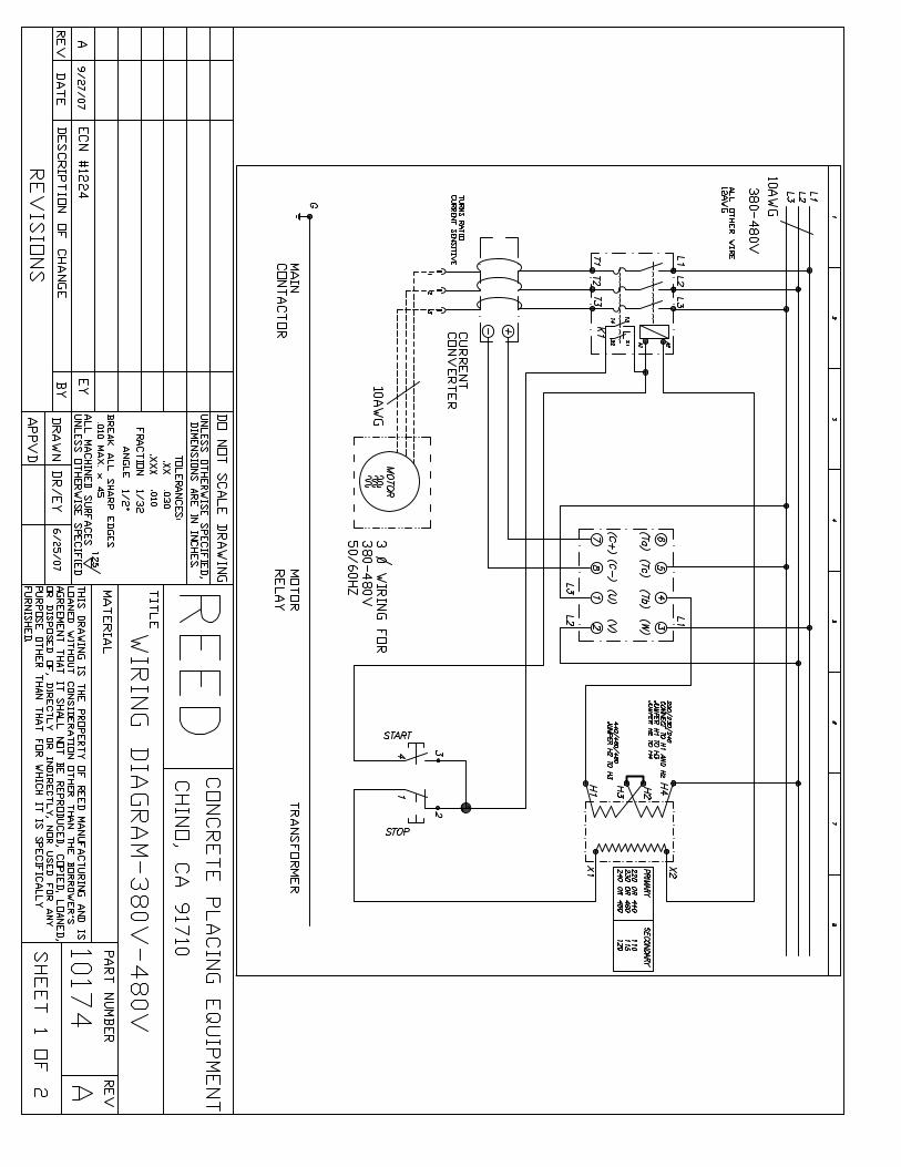
LOHE - PNEUMATIC SPRAYING MACHINE
VENDOR SECTION
LOHE VENDOR
FIGURE 00 PAGE 00
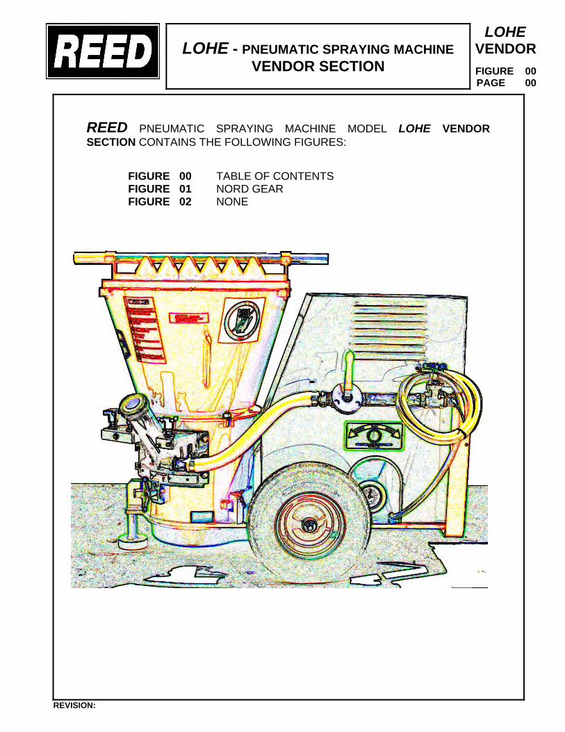
REED PNEUMATIC SPRAYING MACHINE MODEL LOHE VENDOR SECTION CONTAINS THE FOLLOWING FIGURES:
FIGURE 00 TABLE OF CONTENTS FIGURE 01 NORD GEAR FIGURE 02 NONE
REVISION:


IM-4010/2004/03 1 www.nord.com
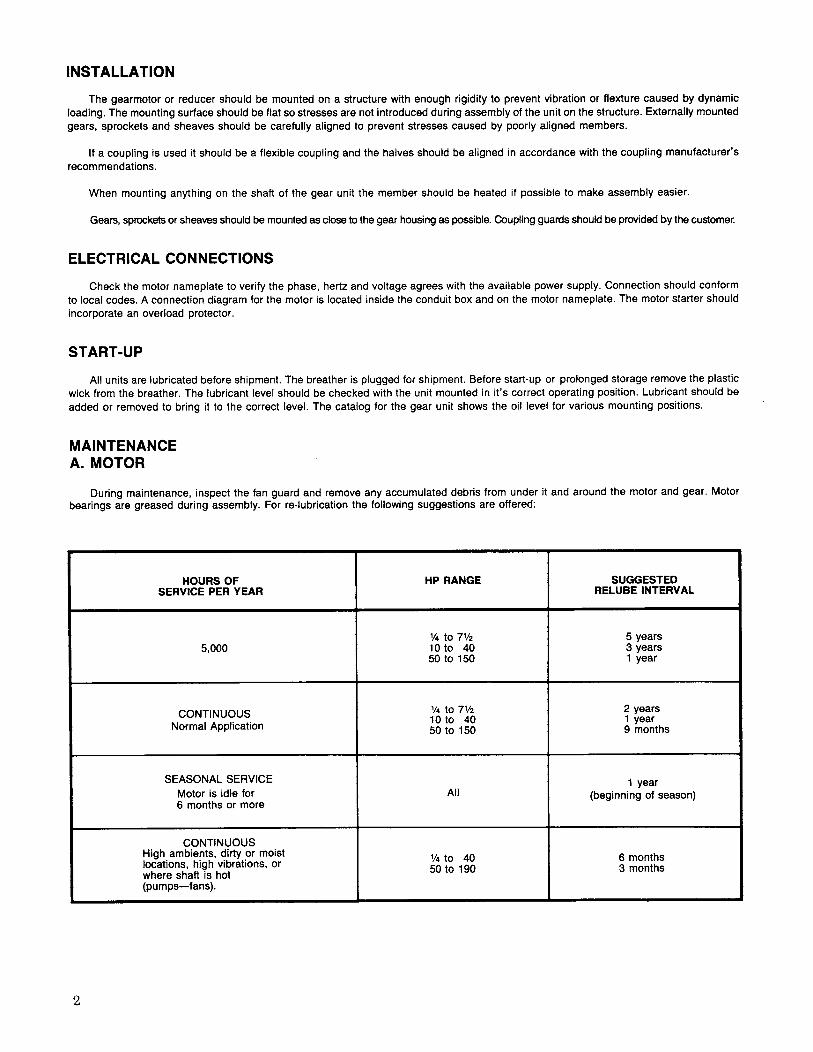
INSPECTION OF UNIT
Thoroughly inspect the equipment for any shipping and handling damage before accepting shipment from the freight company. If any of the goods called for in the bill of lading or express receipt are damaged or the quantity is short, do not accept until the freight or express agent makes an appropriate notation on your freight bill or express receipt. If any concealed loss or damage is discovered later, notify your freight carrier or express agent at once and request him to make an inspection. We will be very happy to assist you in collecting claims for loss or damage during shipment; however, this willingness on our part does not remove the transportation company’s responsibility in reimbursing you for collection of claims or replacement of material. Claims for loss or damage in shipment must not be deducted from the NORD Gear invoice, nor should payment of the NORD Gear invoice be withheld awaiting adjustment of such claims, as the carrier guarantees safe delivery. If considerable damage has been incurred and the situation is urgent, contact the nearest NORD Gear Sales Office for assistance. Please keep a written record of all communications.
RECORD NAMEPLATE DATA
Locate the gear reducer nameplate and record all nameplate data for future reference.
SK ________________________________________________________ S/N _________________________________
RATIO ______________ MAX TORQUE ____________________ RPM ______________ MTG. POS. ______________
BIM-4010/2004 TITAN Adjustable Speed Drives Installation and Maintenance Instructions
Retain These Safety Instructions For Future Use
CDN
USA
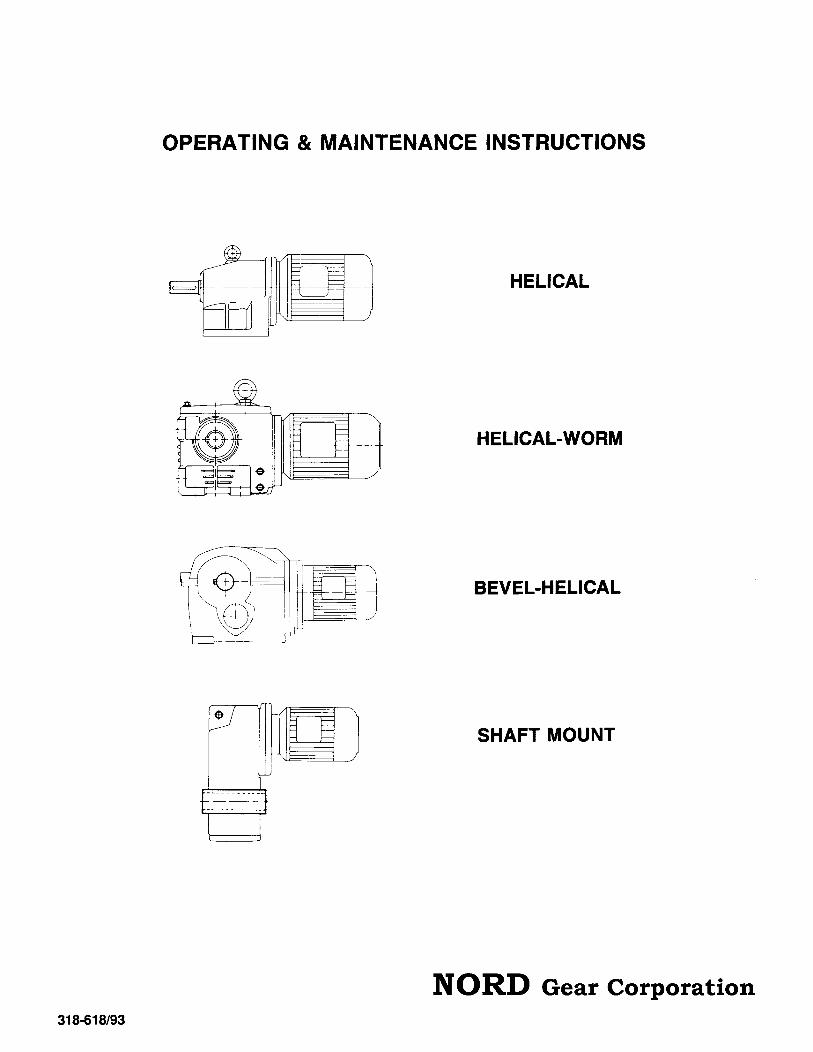
In-Line Helical Parallel Shaft Helical (Clincher)
Helical-Bevel (3-Stage) Helical-Worm
IM-4010/2004/03 2 www.nord.com
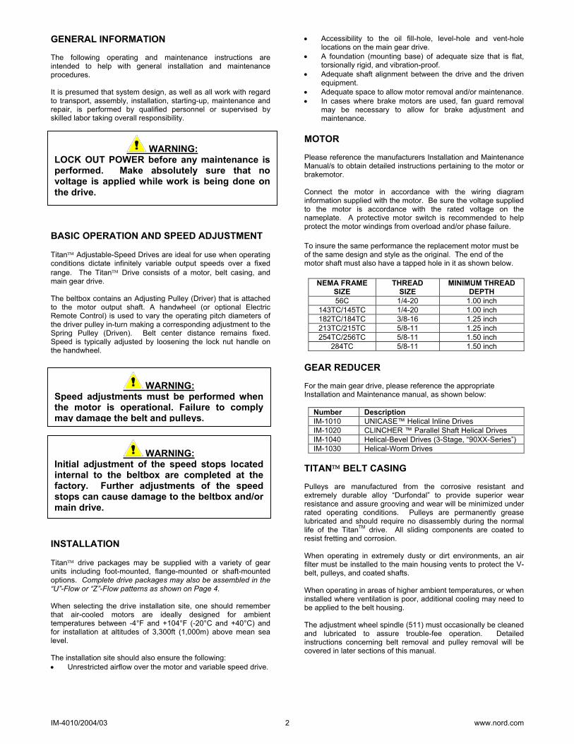
GENERAL INFORMATION The following operating and maintenance instructions are intended to help with general installation and maintenance procedures. It is presumed that system design, as well as all work with regard to transport, assembly, installation, starting-up, maintenance and repair, is performed by qualified personnel or supervised by skilled labor taking overall responsibility. BASIC OPERATION AND SPEED ADJUSTMENT Titan Adjustable-Speed Drives are ideal for use when operating conditions dictate infinitely variable output speeds over a fixed range. The Titan Drive consists of a motor, belt casing, and main gear drive. The beltbox contains an Adjusting Pulley (Driver) that is attached to the motor output shaft. A handwheel (or optional Electric Remote Control) is used to vary the operating pitch diameters of the driver pulley in-turn making a corresponding adjustment to the Spring Pulley (Driven). Belt center distance remains fixed. Speed is typically adjusted by loosening the lock nut handle on the handwheel. INSTALLATION Titan drive packages may be supplied with a variety of gear units including foot-mounted, flange-mounted or shaft-mounted options. Complete drive packages may also be assembled in the “U”-Flow or “Z”-Flow patterns as shown on Page 4. When selecting the drive installation site, one should remember that air-cooled motors are ideally designed for ambient temperatures between -4°F and +104°F (-20°C and +40°C) and for installation at altitudes of 3,300ft (1,000m) above mean sea level. The installation site should also ensure the following: • Unrestricted airflow over the motor and variable speed drive.
• Accessibility to the oil fill-hole, level-hole and vent-hole locations on the main gear drive.
• A foundation (mounting base) of adequate size that is flat, torsionally rigid, and vibration-proof.
• Adequate shaft alignment between the drive and the driven equipment.
• Adequate space to allow motor removal and/or maintenance. • In cases where brake motors are used, fan guard removal
may be necessary to allow for brake adjustment and maintenance.
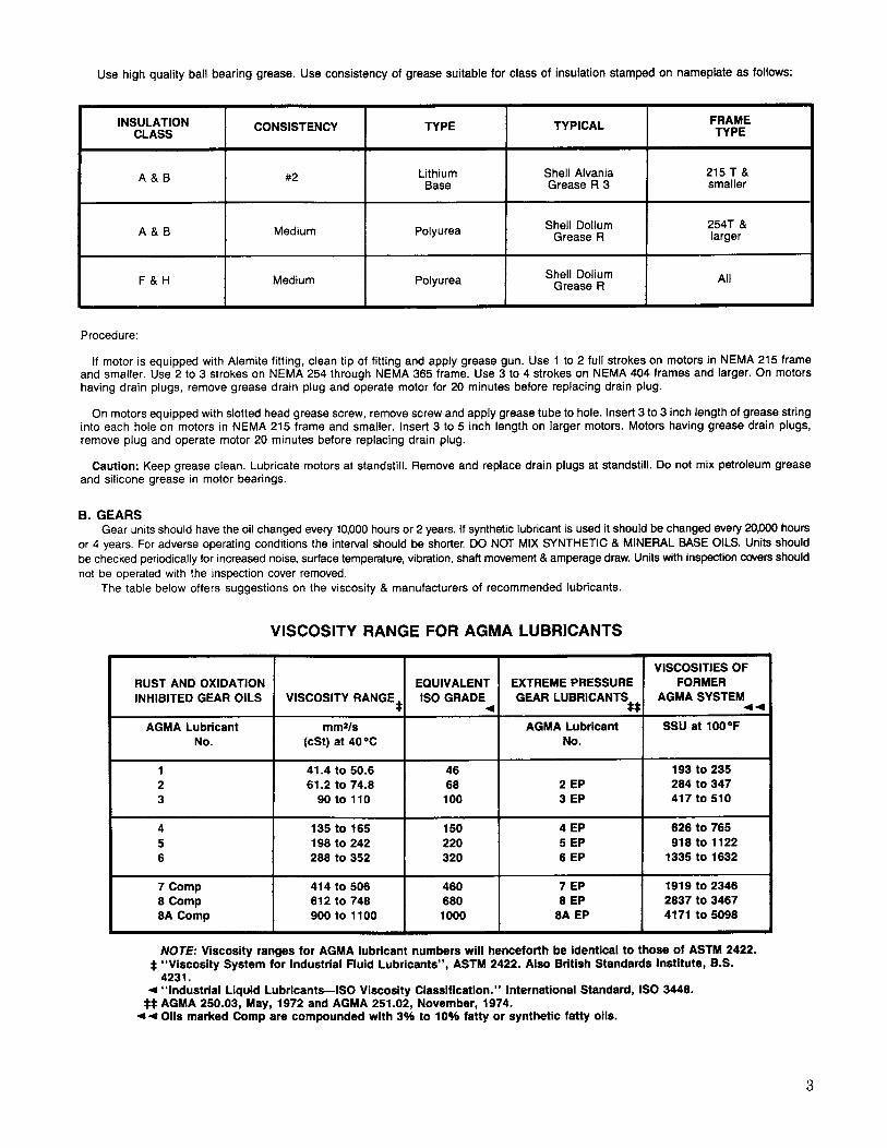
MOTOR Please reference the manufacturers Installation and Maintenance Manual/s to obtain detailed instructions pertaining to the motor or brakemotor. Connect the motor in accordance with the wiring diagram information supplied with the motor. Be sure the voltage supplied to the motor is accordance with the rated voltage on the nameplate. A protective motor switch is recommended to help protect the motor windings from overload and/or phase failure. To insure the same performance the replacement motor must be of the same design and style as the original. The end of the motor shaft must also have a tapped hole in it as shown below.
NEMA FRAME SIZE
THREAD SIZE
MINIMUM THREAD DEPTH
56C 1/4-20 1.00 inch 143TC/145TC 1/4-20 1.00 inch 182TC/184TC 3/8-16 1.25 inch 213TC/215TC 5/8-11 1.25 inch 254TC/256TC 5/8-11 1.50 inch
284TC 5/8-11 1.50 inch GEAR REDUCER For the main gear drive, please reference the appropriate Installation and Maintenance manual, as shown below:
Number Description IM-1010 UNICASE™ Helical Inline Drives IM-1020 CLINCHER ™ Parallel Shaft Helical Drives IM-1040 Helical-Bevel Drives (3-Stage, “90XX-Series”) IM-1030 Helical-Worm Drives
TITAN BELT CASING Pulleys are manufactured from the corrosive resistant and extremely durable alloy “Durfondal” to provide superior wear resistance and assure grooving and wear will be minimized under rated operating conditions. Pulleys are permanently grease lubricated and should require no disassembly during the normal life of the TitanTM drive. All sliding components are coated to resist fretting and corrosion. When operating in extremely dusty or dirt environments, an air filter must be installed to the main housing vents to protect the V-belt, pulleys, and coated shafts. When operating in areas of higher ambient temperatures, or when installed where ventilation is poor, additional cooling may need to be applied to the belt housing. The adjustment wheel spindle (511) must occasionally be cleaned and lubricated to assure trouble-fee operation. Detailed instructions concerning belt removal and pulley removal will be covered in later sections of this manual.
WARNING: LOCK OUT POWER before any maintenance isperformed. Make absolutely sure that novoltage is applied while work is being done onthe drive.
WARNING: Speed adjustments must be performed whenthe motor is operational. Failure to complymay damage the belt and pulleys.
WARNING: Initial adjustment of the speed stops locatedinternal to the beltbox are completed at thefactory. Further adjustments of the speedstops can cause damage to the beltbox and/ormain drive.
IM-4010/2004/03 3 www.nord.com
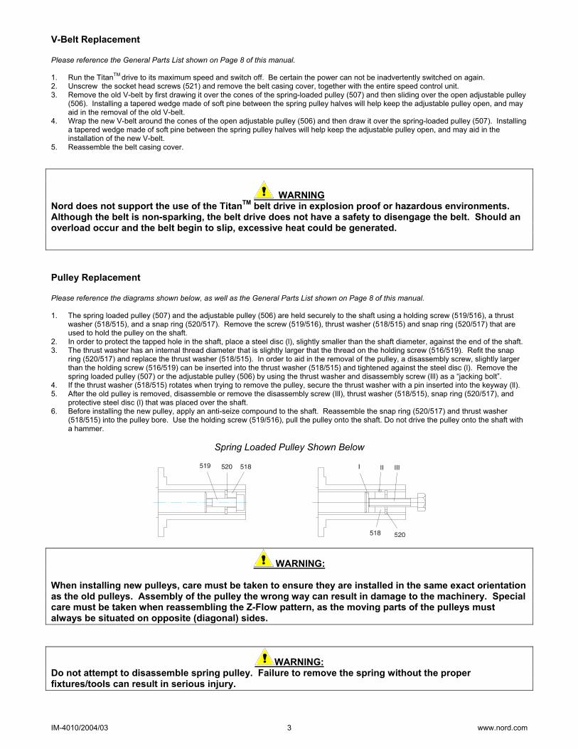
V-Belt Replacement Please reference the General Parts List shown on Page 8 of this manual. 1. Run the TitanTM drive to its maximum speed and switch off. Be certain the power can not be inadvertently switched on again. 2. Unscrew the socket head screws (521) and remove the belt casing cover, together with the entire speed control unit. 3. Remove the old V-belt by first drawing it over the cones of the spring-loaded pulley (507) and then sliding over the open adjustable pulley
(506). Installing a tapered wedge made of soft pine between the spring pulley halves will help keep the adjustable pulley open, and may aid in the removal of the old V-belt.
4. Wrap the new V-belt around the cones of the open adjustable pulley (506) and then draw it over the spring-loaded pulley (507). Installing a tapered wedge made of soft pine between the spring pulley halves will help keep the adjustable pulley open, and may aid in the installation of the new V-belt.
5. Reassemble the belt casing cover.
WARNING Nord does not support the use of the TitanTM belt drive in explosion proof or hazardous environments. Although the belt is non-sparking, the belt drive does not have a safety to disengage the belt. Should an overload occur and the belt begin to slip, excessive heat could be generated.
Pulley Replacement Please reference the diagrams shown below, as well as the General Parts List shown on Page 8 of this manual. 1. The spring loaded pulley (507) and the adjustable pulley (506) are held securely to the shaft using a holding screw (519/516), a thrust
washer (518/515), and a snap ring (520/517). Remove the screw (519/516), thrust washer (518/515) and snap ring (520/517) that are used to hold the pulley on the shaft.
2. In order to protect the tapped hole in the shaft, place a steel disc (l), slightly smaller than the shaft diameter, against the end of the shaft. 3. The thrust washer has an internal thread diameter that is slightly larger that the thread on the holding screw (516/519). Refit the snap
ring (520/517) and replace the thrust washer (518/515). In order to aid in the removal of the pulley, a disassembly screw, slightly larger than the holding screw (516/519) can be inserted into the thrust washer (518/515) and tightened against the steel disc (l). Remove the spring loaded pulley (507) or the adjustable pulley (506) by using the thrust washer and disassembly screw (Ill) as a “jacking bolt”.
4. If the thrust washer (518/515) rotates when trying to remove the pulley, secure the thrust washer with a pin inserted into the keyway (ll). 5. After the old pulley is removed, disassemble or remove the disassembly screw (Ill), thrust washer (518/515), snap ring (520/517), and
protective steel disc (l) that was placed over the shaft. 6. Before installing the new pulley, apply an anti-seize compound to the shaft. Reassemble the snap ring (520/517) and thrust washer
(518/515) into the pulley bore. Use the holding screw (519/516), pull the pulley onto the shaft. Do not drive the pulley onto the shaft with a hammer.
Spring Loaded Pulley Shown Below
WARNING:
When installing new pulleys, care must be taken to ensure they are installed in the same exact orientation as the old pulleys. Assembly of the pulley the wrong way can result in damage to the machinery. Special care must be taken when reassembling the Z-Flow pattern, as the moving parts of the pulleys must always be situated on opposite (diagonal) sides.
WARNING: Do not attempt to disassemble spring pulley. Failure to remove the spring without the proper fixtures/tools can result in serious injury.

IM-4010/2004/03 4 www.nord.com
U-FLOW
Z-FLOW

IM-4010/2004/03 5 www.nord.com
ADJUSTING SPEED WITH OPTIONAL ELECTROMECHANICAL REMOTE CONTROL (ERC) The Electromechanical Remote Control (ERC) replaces the hand wheel when remote speed adjustment is desired. The typical ERC is a worm-gearmotor with limit switches and potentiometer located under the cover of the speed control gearmotor. The limit switches are used to prevent the ERC motor from rotating the spindle adjustment all the way against the mechanical speed stops located inside the friction drive. The friction drive leaves the factory set to the speed range indicated on the nameplate.
NOTE: NORD Gear does not supply the motor starter, overload protection, or push buttons.
Electromechanical Remote Control (ERC) Three Phase Operation Single Phase Operation ERC Part Number 28090100 28090100 28090110 Operating Frequency 60 Hz 50 Hz 60 Hz Power Rating 70 W 70 W 70 W Input Speed 1650 RPM 1375 1650 RPM Supply Voltage 230 ∆ / 460 Υ Volts 230 ∆ / 400 Υ Volts 110-115 Volts Current 0.44-0.25 Amps 0.51-0.29 Amps 1.15 Amps Enclosure TENV TENV TENV Output Speed 30 RPM 25 RPM 30 RPM Limit Switch 15A, 250 V 15 A, 250 V 15A, 250 V
22 kΩ linear 22 kΩ linear 22 kΩ linear turning range: 270° turning range: 270° turning range: 270°
Potentiometer
loading capacity: 0.15 W loading capacity: 0.15 W loading capacity: 0.15 W
IM-4010/2004/03 6 www.nord.com
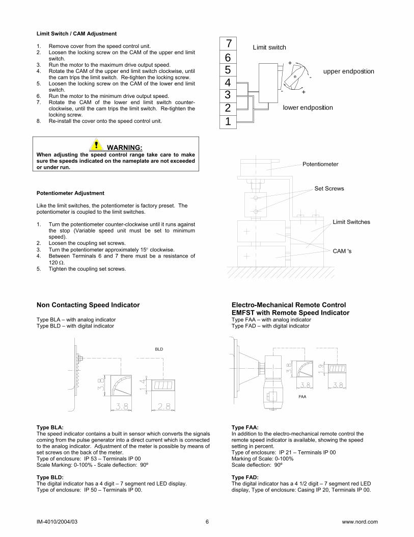
Limit Switch / CAM Adjustment 1. Remove cover from the speed control unit. 2. Loosen the locking screw on the CAM of the upper end limit
switch. 3. Run the motor to the maximum drive output speed. 4. Rotate the CAM of the upper end limit switch clockwise, until
the cam trips the limit switch. Re-tighten the locking screw. 5. Loosen the locking screw on the CAM of the lower end limit
switch. 6. Run the motor to the minimum drive output speed. 7. Rotate the CAM of the lower end limit switch counter-
clockwise, until the cam trips the limit switch. Re-tighten the locking screw.
8. Re-install the cover onto the speed control unit.
WARNING: When adjusting the speed control range take care to make sure the speeds indicated on the nameplate are not exceeded or under run. Potentiometer Adjustment Like the limit switches, the potentiometer is factory preset. The potentiometer is coupled to the limit switches. 1. Turn the potentiometer counter-clockwise until it runs against
the stop (Variable speed unit must be set to minimum speed).
2. Loosen the coupling set screws. 3. Turn the potentiometer approximately 15° clockwise. 4. Between Terminals 6 and 7 there must be a resistance of
120 Ω. 5. Tighten the coupling set screws.
lower endposition
-
+
+
-
2
76543
1
Limit switch
upper endposition
Non Contacting Speed Indicator Electro-Mechanical Remote Control EMFST with Remote Speed Indicator Type BLA – with analog indicator Type FAA – with analog indicator Type BLD – with digital indicator Type FAD – with digital indicator
Type BLA: Type FAA: The speed indicator contains a built in sensor which converts the signals In addition to the electro-mechanical remote control the coming from the pulse generator into a direct current which is connected remote speed indicator is available, showing the speed to the analog indicator. Adjustment of the meter is possible by means of setting in percent. set screws on the back of the meter. Type of enclosure: IP 21 – Terminals IP 00 Type of enclosure: IP 53 – Terminals IP 00 Marking of Scale: 0-100% Scale Marking: 0-100% - Scale deflection: 90º Scale deflection: 90º Type BLD: Type FAD: The digital indicator has a 4 digit – 7 segment red LED display. The digital indicator has a 4 1/2 digit – 7 segment red LED Type of enclosure: IP 50 – Terminals IP 00. display, Type of enclosure: Casing IP 20, Terminals IP 00.

IM-4010/2004/03 7 www.nord.com
NOTES
IM-4010/2004/03 8 www.nord.com
. General Parts Lists

IM-4010/2004/03 9 www.nord.com
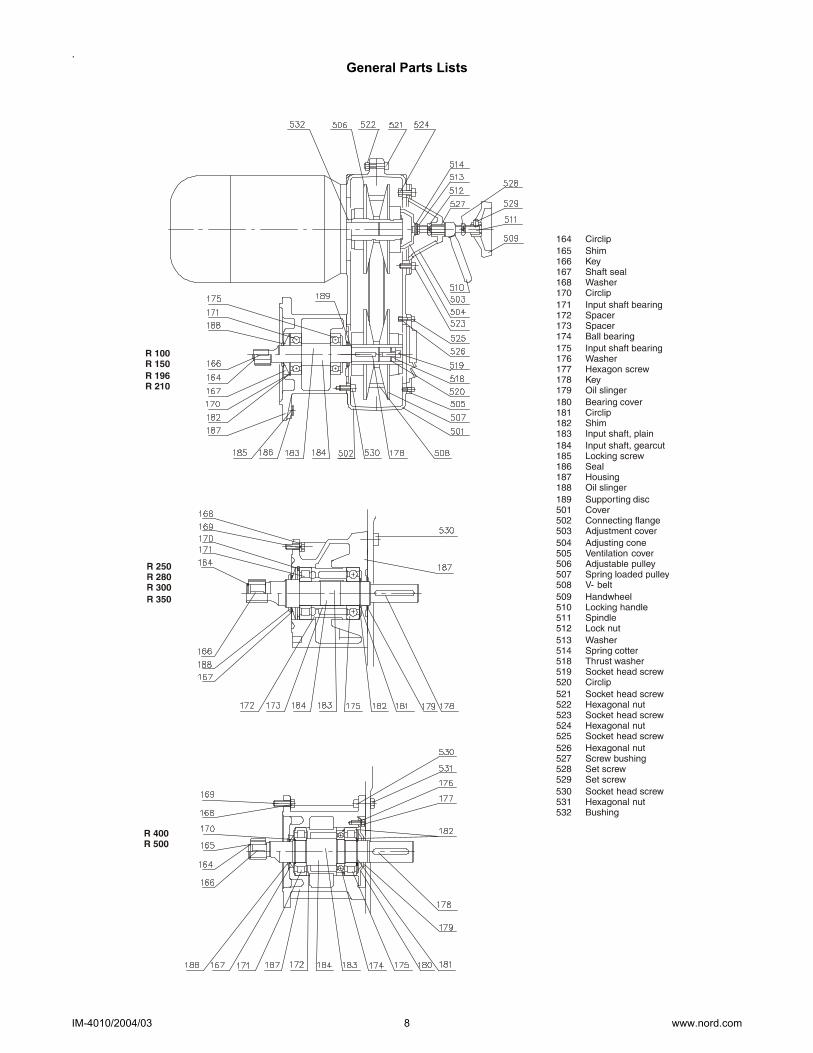
General Parts List
IM-4010/2004/03 10 www.nord.com
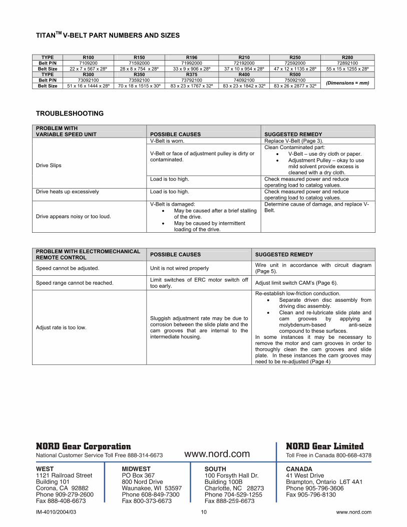
TITANTM V-BELT PART NUMBERS AND SIZES
TYPE R100 R150 R196 R210 R250 R280 Belt P/N 7109200 71592000 71992000 72192000 72592000 72892100 Belt Size 22 x 7 x 567 x 28º 28 x 8 x 754 x 28º 33 x 9 x 906 x 28º 37 x 10 x 954 x 28º 47 x 12 x 1135 x 28º 55 x 15 x 1255 x 28º
TYPE R300 R350 R375 R400 R500 Belt P/N 73092100 73592100 73792100 74092100 75092100 Belt Size 51 x 16 x 1444 x 28º 70 x 18 x 1515 x 30º 83 x 23 x 1767 x 32º 83 x 23 x 1842 x 32º 83 x 26 x 2877 x 32º (Dimensions = mm)
TROUBLESHOOTING PROBLEM WITH VARIABLE SPEED UNIT
POSSIBLE CAUSES
SUGGESTED REMEDY
V-Belt is worn. Replace V-Belt (Page 3). V-Belt or face of adjustment pulley is dirty or contaminated.
Clean Contaminated part: • V-Belt – use dry cloth or paper. • Adjustment Pulley – okay to use
mild solvent provide excess is cleaned with a dry cloth.
Drive Slips
Load is too high. Check measured power and reduce operating load to catalog values.
Drive heats up excessively Load is too high. Check measured power and reduce operating load to catalog values.
Drive appears noisy or too loud.
V-Belt is damaged: • May be caused after a brief stalling
of the drive. • May be caused by intermittent
loading of the drive.
Determine cause of damage, and replace V-Belt.
PROBLEM WITH ELECTROMECHANICAL REMOTE CONTROL POSSIBLE CAUSES SUGGESTED REMEDY
Speed cannot be adjusted. Unit is not wired properly Wire unit in accordance with circuit diagram (Page 5).
Speed range cannot be reached. Limit switches of ERC motor switch off too early. Adjust limit switch CAM’s (Page 6).
Adjust rate is too low.
Sluggish adjustment rate may be due to corrosion between the slide plate and the cam grooves that are internal to the intermediate housing.
Re-establish low-friction conduction. • Separate driven disc assembly from
driving disc assembly. • Clean and re-lubricate slide plate and
cam grooves by applying a molybdenum-based anti-seize compound to these surfaces.
In some instances it may be necessary to remove the motor and cam grooves in order to thoroughly clean the cam grooves and slide plate. In these instances the cam grooves may need to be re-adjusted (Page 4)
BIM 1004/2005/05 Page 1 of 20 www.nord.com
BIM 1004
MOTORS AC Induction, Single and Polyphase
Installation and Maintenance Instructions
Copyright 2005, NORD Gear Corporation
All rights reserved. No part of this book covered by the copyright hereon may be reproduced or copied in any form or by any means without the written permission of the NORD Gear Corporation.
USA
CDN

BIM 1004/2005/05 Page 2 of 20 www.nord.com
NOTES
BIM 1004/2005/05 Page 3 of 20 www.nord.com
TABLE OF CONTENTS
Subject Page Introduction................................................................................................................................................... 4 Description and Operation ............................................................................................................................ 4 Inspection...................................................................................................................................................... 6 Testing and Fault Isolation............................................................................................................................ 7 Lubrication.................................................................................................................................................... 9 Removal, Installation, and Handling............................................................................................................. 9 Connection Diagrams.................................................................................................................................. 12 Repair.......................................................................................................................................................... 13 Parts List ..................................................................................................................................................... 14 Motor Options & Nomenclature ................................................................................................................. 17
LIST OF ILLUSTRATIONS Figure No. Figure Title Page Figure 1 Motor Nameplates............................................................................................................... 5 Figure 2 Motor & Options Connection Diagrams........................................................................... 12 Figure 3 General Motor Exploded View and Generic Parts List (2 pages)..................................... 15
LIST OF TABLES Table No. Table Title Page Table 1 Related Publications ........................................................................................................... 4 Table 2 Nameplate Data................................................................................................................... 5 Table 3 Motor Inspection Criteria.................................................................................................... 6 Table 4 Motor Fault Isolation .......................................................................................................... 8 Table 5 Motor Option Codes & Nomenclature.............................................................................. 17 Table 6 Space Heater Data............................................................................................................. 19 Table 7 Encoder Wiring Designations ........................................................................................... 19 Table 8 Blower Cooling Fan Data ................................................................................................. 20

BIM 1004/2005/05 Page 4 of 20 www.nord.com
INTRODUCTION
1. General
This manual includes general motor description and operation, inspection, testing and fault isolation procedures and information, general lubrication instructions and materials, general installation, removal, and handling instructions, and general repair and parts information.
2. Related Publications
The related publications listed in Table 1 provide additional information to support maintenance and fault isolation of the motor and its installation.
Publication Number
Publication Title
BIM 1001 Hollow Shrink Disc Shaft BIM 1002 Hollow Keyed Shaft and Fixing Element BIM 1003 Expansion Chambers BIM 1004 Motors AC Induction, Single Phase and Polyphase BIM 1009 NORD Gearbox Inputs (Motor Adapters and Couplings) BIM 1010 UNICASE Helical Gearboxes BIM 1011 NORDBLOC Helical Gearboxes BIM 1012 Standard Helical Inline Gearboxes BIM 1020 UNICASE Shaft Mount Gearboxes BIM 1030 UNICASE Helical Worm Gearboxes BIM 1031 MINICASE Worm Gearboxes BIM 1033 SI Design UNIBLOC Worm Gearboxes
BIM 1040 UNICASE 90.1 Helical Bevel Gearboxes BIM 1090 Motor Brakes BIM 1142 NORDBLOC® 92 Series Helical Bevel Gearboxes BIM 4010 Titan Mechanical Adjustable Speed Drives BIM 4020 NORDISC® Friction Disc Mechanical Adjustable Speed Drives
Table 1. Related Publications
DESCRIPTION AND OPERATION
1. General
This manual provides general installation and maintenance information for the NORD family of motors described in this section.
2. Description
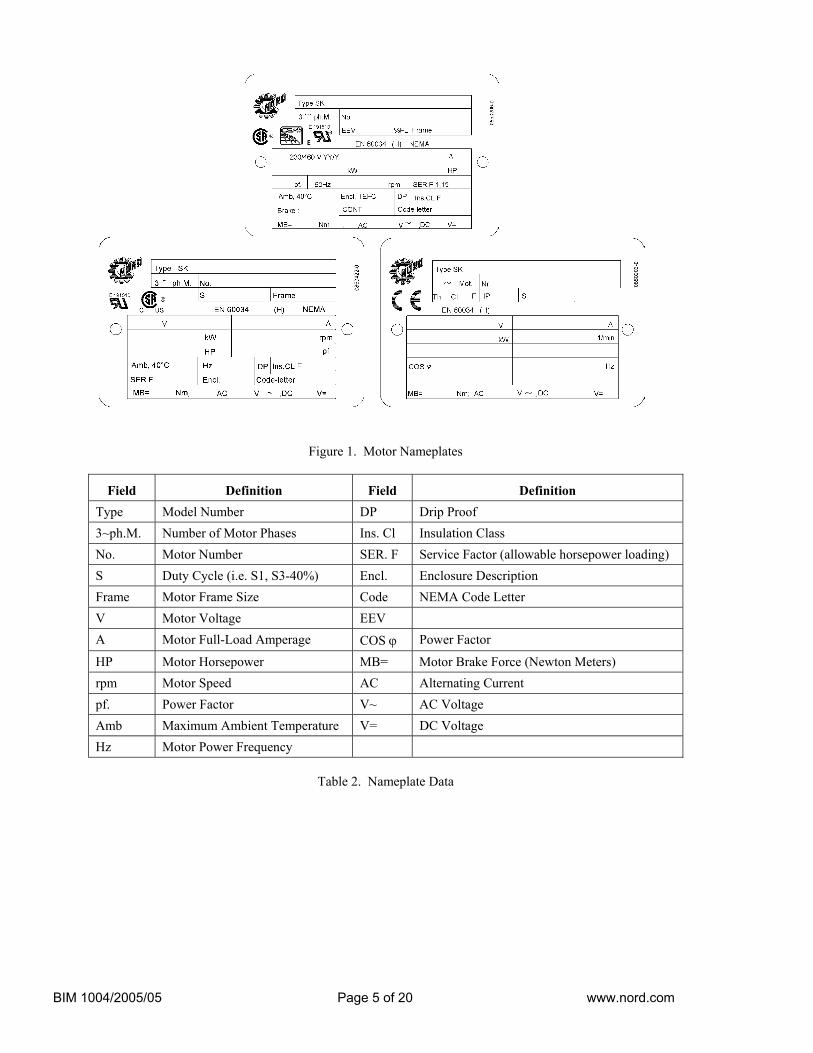
The NORD motors covered in this manual are single phase and poly-phase motors (refer to Table 2), can be single speed or two-speed, and may include the options listed in the Motor Options Section. Motor options, electrical requirements, performance characteristics, and motor data are identified on the motor nameplate. The nameplate drawing is provided in Figure 1. Definition of each entry field is provided in Table 2.
3. Operation
The motors described in this manual are alternating current (AC) induction motors, single speed or two-speed, and convection-cooled, fan cooled, or blower cooled. The motors may use single phase or three phase alternating current.
Cooling options include convection cooling (TENV), fan cooling (TEFC), and blower cooling (TEFB). Because the fan is mounted on the motor shaft, the fan speed is identical to the motor speed, and the cooling capacity varies with the motor speed. The blower uses its own motor and a separate power supply to provide a specific airflow and cooling capacity. The blower power data are provided in Table 8.
BIM 1004/2005/05 Page 5 of 20 www.nord.com
Figure 1. Motor Nameplates
Field Definition Field Definition Type Model Number DP Drip Proof 3~ph.M. Number of Motor Phases Ins. Cl Insulation Class No. Motor Number SER. F Service Factor (allowable horsepower loading) S Duty Cycle (i.e. S1, S3-40%) Encl. Enclosure Description Frame Motor Frame Size Code NEMA Code Letter V Motor Voltage EEV A Motor Full-Load Amperage COS ϕ Power Factor
HP Motor Horsepower MB= Motor Brake Force (Newton Meters) rpm Motor Speed AC Alternating Current pf. Power Factor V~ AC Voltage Amb Maximum Ambient Temperature V= DC Voltage Hz Motor Power Frequency
Table 2. Nameplate Data
BIM 1004/2005/05 Page 6 of 20 www.nord.com
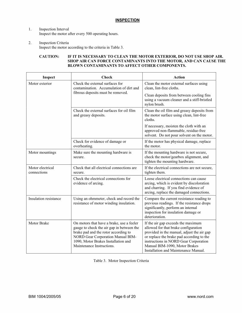
INSPECTION 1. Inspection Interval
Inspect the motor after every 500 operating hours.
2. Inspection Criteria Inspect the motor according to the criteria in Table 3.
CAUTION: IF IT IS NECESSARY TO CLEAN THE MOTOR EXTERIOR, DO NOT USE SHOP AIR.
SHOP AIR CAN FORCE CONTAMINANTS INTO THE MOTOR, AND CAN CAUSE THE BLOWN CONTAMINANTS TO AFFECT OTHER COMPONENTS.
Inspect Check Action Check the external surfaces for contamination. Accumulation of dirt and fibrous deposits must be removed.
Clean the motor external surfaces using clean, lint-free cloths.
Clean deposits from between cooling fins using a vacuum cleaner and a stiff-bristled nylon brush.
Check the external surfaces for oil film and greasy deposits.
Clean the oil film and greasy deposits from the motor surface using clean, lint-free cloths.
If necessary, moisten the cloth with an approved non-flammable, residue-free solvent. Do not pour solvent on the motor.
Motor exterior
Check for evidence of damage or overheating.
If the motor has physical damage, replace the motor.
Motor mountings Make sure the mounting hardware is secure.
If the mounting hardware is not secure, check the motor/gearbox alignment, and tighten the mounting hardware.
Check that all electrical connections are secure.
If the electrical connections are not secure, tighten them.
Motor electrical connections
Check the electrical connections for evidence of arcing.
Loose electrical connections can cause arcing, which is evident by discoloration and charring. If you find evidence of arcing, replace the damaged connections.
Insulation resistance Using an ohmmeter, check and record the resistance of motor winding insulation.
Compare the current resistance reading to previous readings. If the resistance drops significantly, perform an internal inspection for insulation damage or deterioration.
Motor Brake On motors that have a brake, use a feeler gauge to check the air gap in between the brake pad and the rotor according to NORD Gear Corporation Manual BIM-1090, Motor Brakes Installation and Maintenance Instructions.
If the air gap exceeds the maximum allowed for that brake configuration provided in the manual, adjust the air gap or replace the brake pad according to the instructions in NORD Gear Corporation Manual BIM-1090, Motor Brakes Installation and Maintenance Manual.
Table 3. Motor Inspection Criteria
BIM 1004/2005/05 Page 7 of 20 www.nord.com
TESTING AND FAULT ISOLATION
1. General
NOTE: NORD electric motors do not require periodic testing. However, if a motor is removed from its installation, NORD recommends that the motor be checked according to the static and dynamic testing provided below before it is reinstalled. Finding a condition that will require future repair before the motor is reinstalled decreases the overall maintenance time.
This section provides general test information and functional checks for the types of motors covered by this manual. All tests provided below may not apply to all motor types and models. Read and understand the tests and checks before performing them on your motor. Understand how the test or check is to be performed and the pass/fail criteria. Record and date all measurements taken. Retain the measurements in a file. Comparing current and previous measurements is useful in tracking motor condition and brake wear, if the motor is equipped with a brake. If the motor fails any of the test procedures provided below, use the fault isolation procedures to determine the motor problem. Refer to the REPAIR section to determine if the failure is a repairable failure.
2. Testing
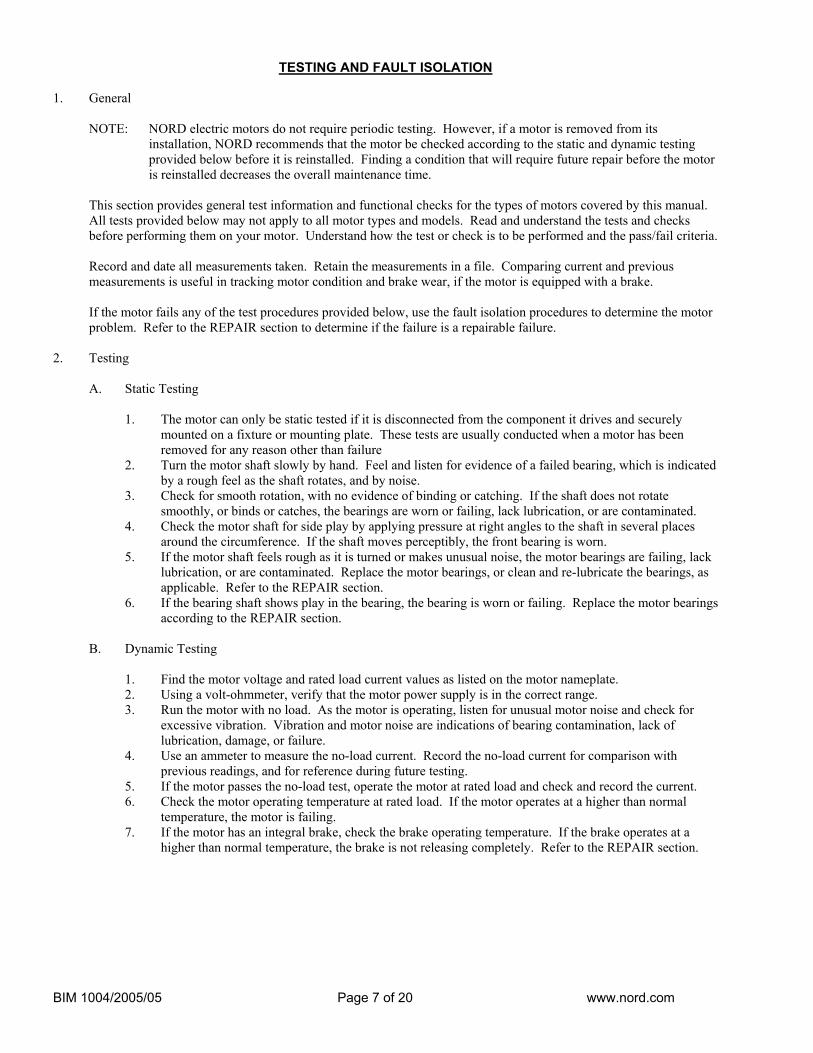
A. Static Testing
1. The motor can only be static tested if it is disconnected from the component it drives and securely mounted on a fixture or mounting plate. These tests are usually conducted when a motor has been removed for any reason other than failure
2. Turn the motor shaft slowly by hand. Feel and listen for evidence of a failed bearing, which is indicated by a rough feel as the shaft rotates, and by noise.
3. Check for smooth rotation, with no evidence of binding or catching. If the shaft does not rotate smoothly, or binds or catches, the bearings are worn or failing, lack lubrication, or are contaminated.
4. Check the motor shaft for side play by applying pressure at right angles to the shaft in several places around the circumference. If the shaft moves perceptibly, the front bearing is worn.
5. If the motor shaft feels rough as it is turned or makes unusual noise, the motor bearings are failing, lack lubrication, or are contaminated. Replace the motor bearings, or clean and re-lubricate the bearings, as applicable. Refer to the REPAIR section.
6. If the bearing shaft shows play in the bearing, the bearing is worn or failing. Replace the motor bearings according to the REPAIR section.
B. Dynamic Testing
1. Find the motor voltage and rated load current values as listed on the motor nameplate. 2. Using a volt-ohmmeter, verify that the motor power supply is in the correct range. 3. Run the motor with no load. As the motor is operating, listen for unusual motor noise and check for
excessive vibration. Vibration and motor noise are indications of bearing contamination, lack of lubrication, damage, or failure.
4. Use an ammeter to measure the no-load current. Record the no-load current for comparison with previous readings, and for reference during future testing.
5. If the motor passes the no-load test, operate the motor at rated load and check and record the current. 6. Check the motor operating temperature at rated load. If the motor operates at a higher than normal
temperature, the motor is failing. 7. If the motor has an integral brake, check the brake operating temperature. If the brake operates at a
higher than normal temperature, the brake is not releasing completely. Refer to the REPAIR section.
BIM 1004/2005/05 Page 8 of 20 www.nord.com
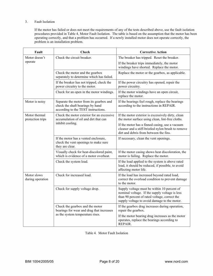
3. Fault Isolation
If the motor has failed or does not meet the requirements of any of the tests described above, use the fault isolation procedures provided in Table 4, Motor Fault Isolation. The table is based on the assumption that the motor has been operating correctly, and that a problem has occurred. If a newly installed motor does not operate correctly, the problem is an installation problem.
Fault Check Corrective Action Check the circuit breaker. The breaker has tripped. Reset the breaker.
If the breaker trips immediately, the motor windings have shorted. Replace the motor.
Check the motor and the gearbox separately to determine which has failed.
Replace the motor or the gearbox, as applicable.
If the breaker has not tripped, check the power circuitry to the motor.
If the power circuitry has opened, repair the power circuitry.
Motor doesn’t operate
Check for an open in the motor windings. If the motor windings have an open circuit, replace the motor.
Motor is noisy Separate the motor from its gearbox and check the shaft bearings by hand according to the TEST instructions.
If the bearings feel rough, replace the bearings according to the instructions in REPAIR.
Check the motor exterior for an excessive accumulation of oil and dirt that can inhibit cooling.
If the motor exterior is excessively dirty, clean the motor surface using clean, lint-free cloths.
If the motor has a finned casing, use a vacuum cleaner and a stiff-bristled nylon brush to remove dirt and debris from between the fins.
If the motor has a vented enclosure, check the vent openings to make sure they are clear.
If necessary, clean the vent openings.
Visually check for heat-discolored paint, which is evidence of a motor overheat.
If the motor casing shows heat discoloration, the motor is failing. Replace the motor.
Motor thermal protection trips
Check the system load. If the load applied to the system is above rated load, it should be reduced, if possible, to avoid affecting motor life.
Check for increased load. If the load has increased beyond rated load, correct the overload condition to prevent damage to the motor.
Check for supply voltage drop. Supply voltage must be within 10 percent of nominal voltage. If the supply voltage is less than 90 percent of rated voltage, correct the supply voltage to avoid damage to the motor.
Motor slows during operation
Check the gearbox and the motor bearings for wear and drag that increases as the system temperature rises.
If the gearbox drag increases during operation, repair the gearbox.
If the motor bearing drag increases as the motor operates, replace the bearings according to REPAIR.
Table 4. Motor Fault Isolation
BIM 1004/2005/05 Page 9 of 20 www.nord.com
LUBRICATION
1. General NORD motor frame sizes 63 up to and including 225 are prelubricated, therefor require no lubrication during normal
operation.
Frame sizes 250 and larger will have grease fittings for regreasing the motor bearings. Relubricate bearings every six months (more often if conditions require) using a polyurea base grease, No. 2 consistency & stabilized against oxidation.
REMOVAL, INSTALLATION, AND HANDLING
1. General
Removing, installing, and handling any NORD electric motor follow the same general procedures. Follow the general procedures provided below. Observe all WARNINGs and CAUTIONs. If you have any questions about the procedure to use to handle, install, or remove a specific motor, call NORD Gear Corporation. Please read the following WARNINGS & CAUTIONS prior to any work on the motor. WARNING:
IF THE MOTOR HAS AN INTEGRAL BRAKE, VERIFY THAT THERE IS NO LOAD ON THE GEARBOX BEFORE RELEASING THE BRAKE. THIS WILL PREVENT POSSIBLE INJURY AND POTENTIAL EQUIPMENT DAMAGE FROM A DROPPED LOAD.
WARNING:
THE MOTOR ELECTRICAL POWER HAS DANGEROUS CURRENT LEVELS. TO PREVENT SERIOUS INJURY, SHUT DOWN THE POWER TO THE MOTOR AT ITS CIRCUIT BREAKER OR POWER SWITCH BEFORE REMOVING OR INSTALLING ANY MOTOR. LOCK OUT THE BREAKER OR SWITCH AND POST IT WITH AN “OUT OF SERVICE” PLACARD.
WARNING:
LARGE MOTORS ARE HEAVY, EASY TO UNBALANCE, AND ARE AWKWARD TO LIFT AND MOVE. EVEN SMALLER MOTORS ARE HEAVY. HAVE ASSISTANCE WHEN LIFTING AND MOVING HEAVY MOTORS. IF NECESSARY, USE APPROPRIATE LIFTING DEVICES TO LIFT AND MOVE HEAVY MOTORS.
CAUTION: TO PREVENT DAMAGE TO THE MOTORSHAFT, BEARINGS, AND THE MATING
HUB/SHEAVE IN THE GEARBOX, MAINTAIN SHAFT ALIGNMENT WHILE REMOVING THE MOTOR FROM ITS GEARBOX.
2. Removal
A. Drain the oil from the mating gearbox, or rotate the motor/gearbox assembly so that the motor is up, to prevent oil from spilling from the gearbox when the motor is removed.
B. Shut down the power to the motor at the main circuit breaker or power switch. Lock out the breaker or switch and place an “OUT OF SERVICE” placard on the breaker or switch.
C. Disconnect the wiring to the motor. Tag each wire as it is disconnected. D. Prepare the motor for removal by supporting the motor appropriately. For smaller motors, use assistance to
steady the motor or support it. For larger motors, use mechanical lifting or support devices to steady and support the motor.
E. Remove the bolts and washers securing the motor to the its mounting. F. Maintain motor shaft alignment, and move the motor away from its mounting pad until the motor shaft clears
its mating hub/sheave or gearmesh. If the motor shaft is a keyed shaft, keep the drive key with the motor. G. Remove and discard the flange gasket. Clean the gasket material from the flange.
BIM 1004/2005/05 Page 10 of 20 www.nord.com
3. Installation with NEMA and IEC Flanges
Refer to NORD Gearbox Inputs Installation and Maintenance Instructions in BIM1009. A. Make sure the flanges are clean and free of gasket material. Install a new gasket between the mating flanges, if
applicable. B. Carefully move the motor to insert the motor shaft and its hub/sheave into the adapter spline, making sure the
shaft key enters the mating keyway. C. Seat the motor flange against the mating flange. Install the mounting bolts and tighten them securely. D. Reconnect the wiring to the motor. Refer to Figure 2 for the motor and options connection diagrams.
4. Removing and Replacing C-Face Motors
A. Shut off the power to the motor and post the shutoff with an “OUT OF SERVICE” placard. Disconnect the
wiring to the motor. Tag each wire as it is disconnected. B. Support the motor. Remove four bolts securing the motor to the NEMA or IEC adapter.
NOTE: The bolts securing the motor to the adapter are retained using a medium strength thread locker such
as blue Loctite. C. Pull the motor straight out from the adapter. D. Measure and record the dimension from the coupling to the motor flange. Use this dimension to locate the
coupling on the replacement motor. E. Install a new drive key in the keyway, staking the key or using Loctite to retain the key in the keyway,
according to the following instructions:
1) If the drive key is not trapped in the keyway (the keyway is open at both ends), stake and install the drive key as follows:
a. Make sure the keyway is free of contamination so that the drive key will seat properly. b. Add a few drops of an approved lubricant to the keyway. c. Place the drive key on an appropriate surface with the shaft side of the drive key up. Stake the
key in two places near each long edge to deform the edge outward. CAUTION: SUPPORT THE MOTOR SHAFT BEFORE STAKING THE KEY TO PREVENT
DAMAGE TO THE MOTOR BEARINGS. d. Support the motor shaft in V-blocks. Place the key with the staked surface down over the key
slot. Place a sheet of copper shimstock, or equivalent, on the drive key and tap it into the keyway using a hammer.
e. Check the key to make sure it is fully seated and securely retained.
2) Install and Loctite the drive key as follows:
a. Make sure the keyway is clean of old Loctite and is free of oil film. b. Apply Loctite primer and medium strength (blue) Loctite to the surface of the key and keyway
according to the Loctite instructions. CAUTION: IF THE DRIVE KEY IS TO BE LOCTITED IN PLACE, CLEAN ALL THE
LOCTITE FROM THE SURFACE OF THE DRIVE KEY AND THE MOTOR SHAFT TO PREVENT POSSIBLE BONDING OF THE COUPLING AND SPLINE SHAFT TO THE DRIVE KEY.
c. Install the drive key and center it in the keyway. Cure the Loctite according to Loctite
instructions.
BIM 1004/2005/05 Page 11 of 20 www.nord.com
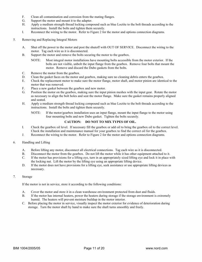
F. Clean all contamination and corrosion from the mating flanges. G. Support the motor and mount it to the adapter. H. Apply a medium strength thread locking compound such as blue Loctite to the bolt threads according to the
instructions. Install the bolts and tighten them securely. I. Reconnect the wiring to the motor. Refer to Figure 2 for the motor and options connection diagrams.
5. Removing and Replacing Integral Motors
A. Shut off the power to the motor and post the shutoff with OUT OF SERVICE. Disconnect the wiring to the motor. Tag each wire as it is disconnected.
B. Support the motor and remove the bolts securing the motor to the gearbox.
NOTE: Most integral motor installations have mounting bolts accessible from the motor exterior. If the bolts are not visible, unbolt the input flange from the gearbox. Remove four bolts that mount the motor. Remove and discard the Dubo gaskets from the bolts.
C. Remove the motor from the gearbox. D. Clean the gasket faces on the motor and gearbox, making sure no cleaning debris enters the gearbox. E. Check the replacement motor to make sure the motor flange, motor shaft, and motor pinion are identical to the
motor that was removed. F. Place a new gasket between the gearbox and new motor. G. Position the motor on the gearbox, making sure the input pinion meshes with the input gear. Rotate the motor
as necessary to align the bolt holes and seat the motor flange. Make sure the gasket remains properly aligned and seated.
H. Apply a medium strength thread locking compound such as blue Loctite to the bolt threads according to the instructions. Install the bolts and tighten them securely.
NOTE: If the motor/gearbox installation uses an input flange, mount the input flange to the motor using four mounting bolts and new Dubo gasket. Tighten the bolts securely.
CAUTION: DO NOT TO MIX TYPES OF OIL.
I. Check the gearbox oil level. If necessary fill the gearbox or add oil to bring the gearbox oil to the correct level. Check the installation and maintenance manual for your gearbox to find the correct oil for the gearbox.
J. Reconnect the wiring to the motor. Refer to Figure 2 for the motor and options connection diagrams. 6. Handling and Lifting
A. Before lifting any motor, disconnect all electrical connections. Tag each wire as it is disconnected. B. Disconnect the motor from the gearbox. Do not lift the motor while it has other equipment attached to it. C. If the motor has provisions for a lifting eye, turn in an appropriately sized lifting eye and lock it in place with
the locking nut. Lift the motor by the lifting eye using an appropriate lifting device. D. If the motor does not have provisions for a lifting eye, seek assistance or use appropriate lifting devices as
necessary. 7. Storage
If the motor is not in service, store it according to the following conditions:
A. Cover the motor and store it in a clean warehouse environment protected from dust and fluids. B. If the motor has internal heaters, power the heaters during storage if the storage environment is extremely
humid. The heaters will prevent moisture buildup in the motor interior. C. Before placing the motor in service, visually inspect the motor exterior for evidence of deterioration during
storage. Turn the motor shaft by hand to make sure the shaft turns smoothly and freely.
BIM 1004/2005/05 Page 12 of 20 www.nord.com
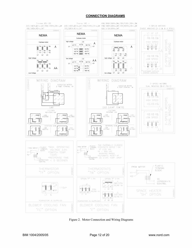
CONNECTION DIAGRAMS
NEMA
L3L1
V2 T5U2 T4W2 T6
high voltage
U1 T1 V1 T2
L2
W1 T3
Y
3-phase motor
Y
V2 T5
W2 T6U2 T4
V5 T8U5 T7W5 T9
Ylow voltage
L1
L2
L3U1 T1 W1 T3
V5 T8U5 T7W5 T9
V1 T2
NEMA
3-phase motor
high voltage
low voltage
T1 T2 T3
T6 T4 T5
L1 L2 L3
T5V2
T3
T4T6
L3L2L1
W2 U2
T2T1
Y
W2 V2U2
W1V1U1
U1 V1 W1
NEMA
3-phase motor
High Voltage
Low Voltage
T4
T1 T2 T3
T5 T6
T7 T8 T9
L1 L2 L3
T6
T9
T3
T5T4
L3L2L1
T7 T8
T2T1
Y
YY
Figure 2. Motor Connection and Wiring Diagrams
BIM 1004/2005/05 Page 13 of 20 www.nord.com
REPAIR 1. General
These instructions can be generally applied to NORD motor applications. The exploded view provided in the PARTS INFORMATION section shows the parts orientation for NORD motors. To procure replacement parts from NORD, contact NORD’s customer service department (refer to INTRODUCTION). Provide NORD with the motor part number and serial number, and the item reference number and nomenclature from the parts information figure, which will identify the part for your motor application.
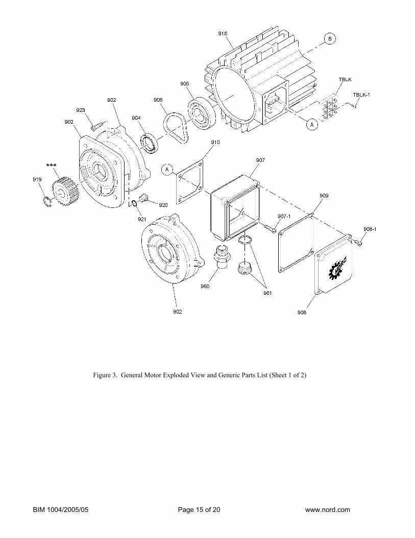
A. The following parts must be replaced if they are removed:
• Oil seal (904), Oil seal (933) • Gasket (909), Gasket (910), Gasket (921) • Gasket on plug (961) • Self-locking screws (907-1, 908-1, 923, 932-1, 940-1)
B. If the following parts are removed, inspect them, and replace them if they are deformed:
• Retaining ring (919), Retaining ring (947), Retaining ring (948) • Fan clip (952)
C. Disassemble the motor according to the general exploded view in PARTS INFORMATION. Disassemble
only as far as necessary to replace the failed parts. D. Whenever the motor is disassembled, clean all dust and contamination from the motor interior using a
vacuum cleaner and a soft-bristled nylon brush.
BIM 1004/2005/05 Page 14 of 20 www.nord.com
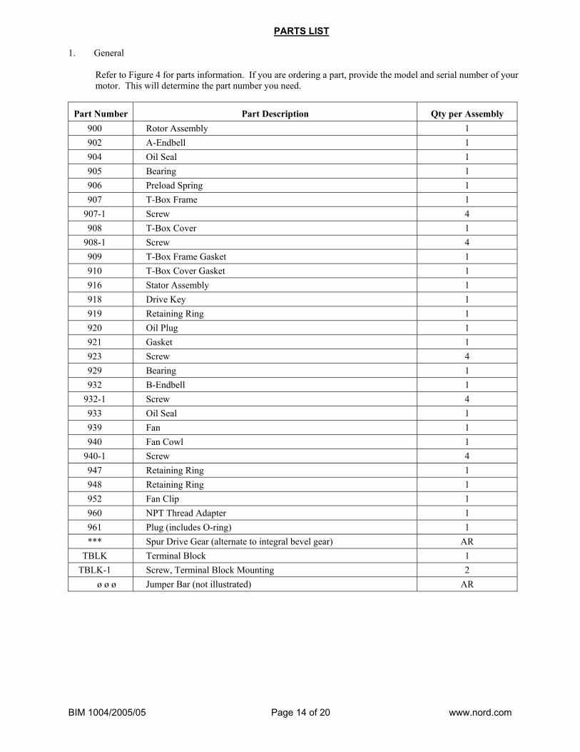
PARTS LIST 1. General
Refer to Figure 4 for parts information. If you are ordering a part, provide the model and serial number of your motor. This will determine the part number you need.
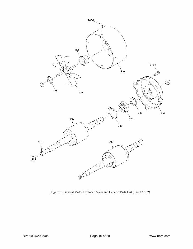
Part Number Part Description Qty per Assembly 900 Rotor Assembly 1 902 A-Endbell 1 904 Oil Seal 1 905 Bearing 1 906 Preload Spring 1 907 T-Box Frame 1
907-1 Screw 4 908 T-Box Cover 1
908-1 Screw 4 909 T-Box Frame Gasket 1 910 T-Box Cover Gasket 1 916 Stator Assembly 1 918 Drive Key 1 919 Retaining Ring 1 920 Oil Plug 1 921 Gasket 1 923 Screw 4 929 Bearing 1 932 B-Endbell 1
932-1 Screw 4 933 Oil Seal 1 939 Fan 1 940 Fan Cowl 1
940-1 Screw 4 947 Retaining Ring 1 948 Retaining Ring 1 952 Fan Clip 1 960 NPT Thread Adapter 1 961 Plug (includes O-ring) 1 *** Spur Drive Gear (alternate to integral bevel gear) AR
TBLK Terminal Block 1 TBLK-1 Screw, Terminal Block Mounting 2
ø ø ø Jumper Bar (not illustrated) AR
BIM 1004/2005/05 Page 15 of 20 www.nord.com
Figure 3. General Motor Exploded View and Generic Parts List (Sheet 1 of 2)
BIM 1004/2005/05 Page 16 of 20 www.nord.com
Figure 3. General Motor Exploded View and Generic Parts List (Sheet 2 of 2)
BIM 1004/2005/05 Page 17 of 20 www.nord.com
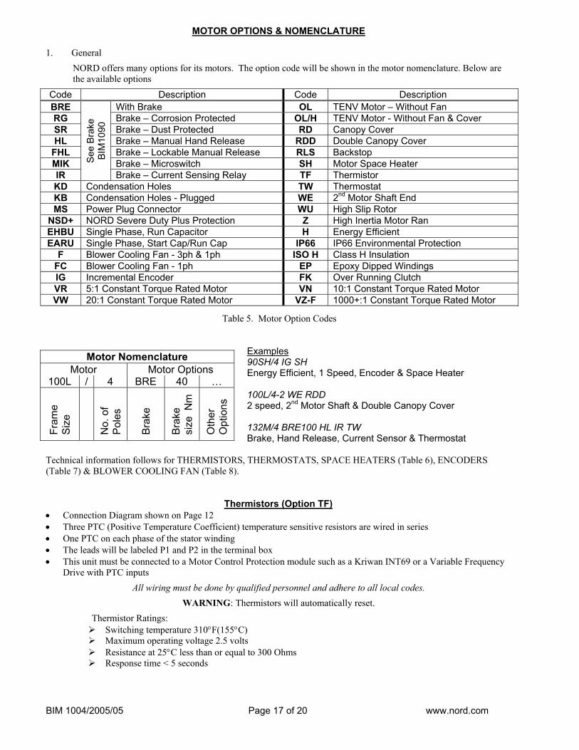
MOTOR OPTIONS & NOMENCLATURE 1. General
NORD offers many options for its motors. The option code will be shown in the motor nomenclature. Below are the available options
Code Description Code Description BRE With Brake OL TENV Motor – Without Fan RG Brake – Corrosion Protected OL/H TENV Motor - Without Fan & Cover SR Brake – Dust Protected RD Canopy Cover HL Brake – Manual Hand Release RDD Double Canopy Cover
FHL Brake – Lockable Manual Release RLS Backstop MIK Brake – Microswitch SH Motor Space Heater IR
See
Brak
e BI
M10
90
Brake – Current Sensing Relay TF Thermistor KD Condensation Holes TW Thermostat KB Condensation Holes - Plugged WE 2nd Motor Shaft End MS Power Plug Connector WU High Slip Rotor
NSD+ NORD Severe Duty Plus Protection Z High Inertia Motor Ran EHBU Single Phase, Run Capacitor H Energy Efficient EARU Single Phase, Start Cap/Run Cap IP66 IP66 Environmental Protection
F Blower Cooling Fan - 3ph & 1ph ISO H Class H Insulation FC Blower Cooling Fan - 1ph EP Epoxy Dipped Windings IG Incremental Encoder FK Over Running Clutch VR 5:1 Constant Torque Rated Motor VN 10:1 Constant Torque Rated Motor VW 20:1 Constant Torque Rated Motor VZ-F 1000+:1 Constant Torque Rated Motor
Table 5. Motor Option Codes
Examples 90SH/4 IG SH Energy Efficient, 1 Speed, Encoder & Space Heater 100L/4-2 WE RDD 2 speed, 2nd Motor Shaft & Double Canopy Cover 132M/4 BRE100 HL IR TW Brake, Hand Release, Current Sensor & Thermostat
Technical information follows for THERMISTORS, THERMOSTATS, SPACE HEATERS (Table 6), ENCODERS (Table 7) & BLOWER COOLING FAN (Table 8).
Thermistors (Option TF) • Connection Diagram shown on Page 12 • Three PTC (Positive Temperature Coefficient) temperature sensitive resistors are wired in series • One PTC on each phase of the stator winding • The leads will be labeled P1 and P2 in the terminal box • This unit must be connected to a Motor Control Protection module such as a Kriwan INT69 or a Variable Frequency
Drive with PTC inputs
All wiring must be done by qualified personnel and adhere to all local codes.
WARNING: Thermistors will automatically reset.
Thermistor Ratings: Switching temperature 310°F(155°C) Maximum operating voltage 2.5 volts Resistance at 25°C less than or equal to 300 Ohms Response time < 5 seconds
Motor Nomenclature Motor Motor Options
100L / 4 BRE 40 …
Fram
e Si
ze
No.
of
Pole
s
Brak
e
Brak
e si
ze N
m
Oth
er
Opt
ions
BIM 1004/2005/05 Page 18 of 20 www.nord.com
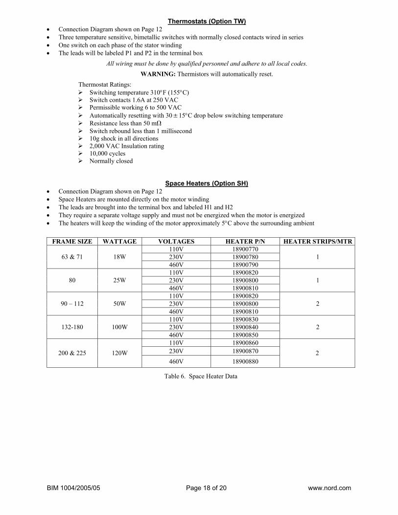
Thermostats (Option TW) • Connection Diagram shown on Page 12 • Three temperature sensitive, bimetallic switches with normally closed contacts wired in series • One switch on each phase of the stator winding • The leads will be labeled P1 and P2 in the terminal box
All wiring must be done by qualified personnel and adhere to all local codes.
WARNING: Thermistors will automatically reset.
Thermostat Ratings: Switching temperature 310°F (155°C) Switch contacts 1.6A at 250 VAC Permissible working 6 to 500 VAC Automatically resetting with 30±15°C drop below switching temperature Resistance less than 50 mΩ Switch rebound less than 1 millisecond 10g shock in all directions 2,000 VAC Insulation rating 10,000 cycles Normally closed
Space Heaters (Option SH) • Connection Diagram shown on Page 12 • Space Heaters are mounted directly on the motor winding • The leads are brought into the terminal box and labeled H1 and H2 • They require a separate voltage supply and must not be energized when the motor is energized • The heaters will keep the winding of the motor approximately 5°C above the surrounding ambient
FRAME SIZE WATTAGE VOLTAGES HEATER P/N HEATER STRIPS/MTR110V 18900770 230V 18900780 63 & 71 18W 460V 18900790
1
110V 18900820 230V 18900800 80 25W 460V 18900810
1
110V 18900820 230V 18900800 90 – 112 50W 460V 18900810
2
110V 18900830 230V 18900840 132-180 100W 460V 18900850
2
110V 18900860 230V 18900870 200 & 225 120W 460V 18900880
2
Table 6. Space Heater Data
BIM 1004/2005/05 Page 19 of 20 www.nord.com
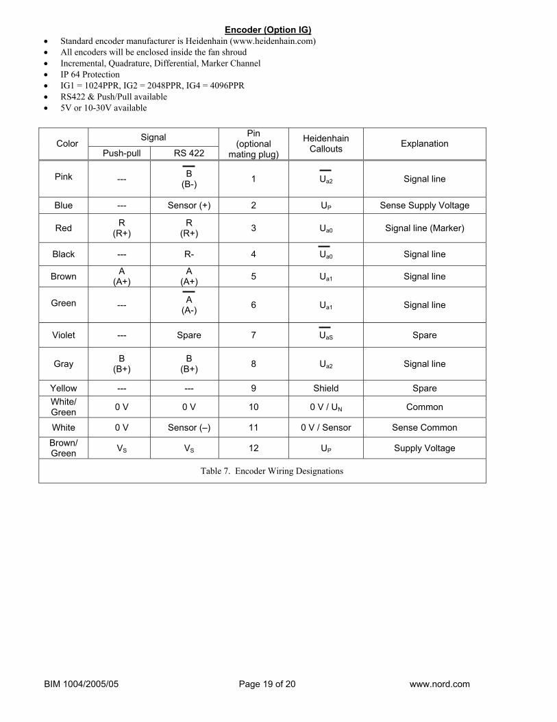
Encoder (Option IG) • Standard encoder manufacturer is Heidenhain (www.heidenhain.com) • All encoders will be enclosed inside the fan shroud • Incremental, Quadrature, Differential, Marker Channel • IP 64 Protection • IG1 = 1024PPR, IG2 = 2048PPR, IG4 = 4096PPR • RS422 & Push/Pull available • 5V or 10-30V available
Signal Color
Push-pull RS 422
Pin (optional
mating plug)
Heidenhain Callouts Explanation
Pink --- B
(B-) 1 Ua2 Signal line
Blue --- Sensor (+) 2 UP Sense Supply Voltage
Red R (R+)
R (R+) 3 Ua0 Signal line (Marker)
Black --- R- 4 Ua0 Signal line
Brown A (A+)
A (A+) 5 Ua1 Signal line
Green --- A
(A-) 6 Ua1 Signal line
Violet --- Spare 7 UaS Spare
Gray B (B+)
B (B+) 8 Ua2 Signal line
Yellow --- --- 9 Shield Spare White/ Green 0 V 0 V 10 0 V / UN Common
White 0 V Sensor (–) 11 0 V / Sensor Sense Common Brown/ Green VS VS 12 UP Supply Voltage
Table 7. Encoder Wiring Designations
BIM 1004/2005/05 Page 20 of 20 www.nord.com
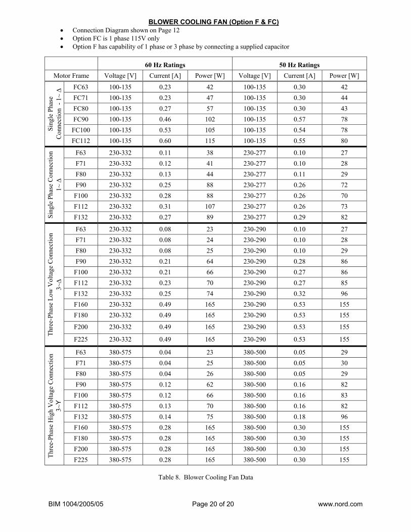
BLOWER COOLING FAN (Option F & FC) • Connection Diagram shown on Page 12 • Option FC is 1 phase 115V only • Option F has capability of 1 phase or 3 phase by connecting a supplied capacitor
60 Hz Ratings 50 Hz Ratings Motor Frame Voltage [V] Current [A] Power [W] Voltage [V] Current [A] Power [W]
FC63 100-135 0.23 42 100-135 0.30 42 FC71 100-135 0.23 47 100-135 0.30 44 FC80 100-135 0.27 57 100-135 0.30 43 FC90 100-135 0.46 102 100-135 0.57 78 FC100 100-135 0.53 105 100-135 0.54 78 Si
ngle
Pha
se
Con
nect
ion
- 1~
∆
FC112 100-135 0.60 115 100-135 0.55 80
F63 230-332 0.11 38 230-277 0.10 27 F71 230-332 0.12 41 230-277 0.10 28 F80 230-332 0.13 44 230-277 0.11 29 F90 230-332 0.25 88 230-277 0.26 72
F100 230-332 0.28 88 230-277 0.26 70 F112 230-332 0.31 107 230-277 0.26 73
Sing
le P
hase
Con
nect
ion
1~ ∆
F132 230-332 0.27 89 230-277 0.29 82
F63 230-332 0.08 23 230-290 0.10 27 F71 230-332 0.08 24 230-290 0.10 28 F80 230-332 0.08 25 230-290 0.10 29 F90 230-332 0.21 64 230-290 0.28 86
F100 230-332 0.21 66 230-290 0.27 86 F112 230-332 0.23 70 230-290 0.27 85 F132 230-332 0.25 74 230-290 0.32 96 F160 230-332 0.49 165 230-290 0.53 155 F180 230-332 0.49 165 230-290 0.53 155
F200 230-332 0.49 165 230-290 0.53 155
Thre
e-Ph
ase
Low
Vol
tage
Con
nect
ion
3~∆
F225 230-332 0.49 165 230-290 0.53 155
F63 380-575 0.04 23 380-500 0.05 29 F71 380-575 0.04 25 380-500 0.05 30 F80 380-575 0.04 26 380-500 0.05 29 F90 380-575 0.12 62 380-500 0.16 82
F100 380-575 0.12 66 380-500 0.16 83 F112 380-575 0.13 70 380-500 0.16 82 F132 380-575 0.14 75 380-500 0.18 96 F160 380-575 0.28 165 380-500 0.30 155 F180 380-575 0.28 165 380-500 0.30 155 F200 380-575 0.28 165 380-500 0.30 155
Thre
e-Ph
ase
Hig
h V
olta
ge C
onne
ctio
n 3~
Y
F225 380-575 0.28 165 380-500 0.30 155
Table 8. Blower Cooling Fan Data

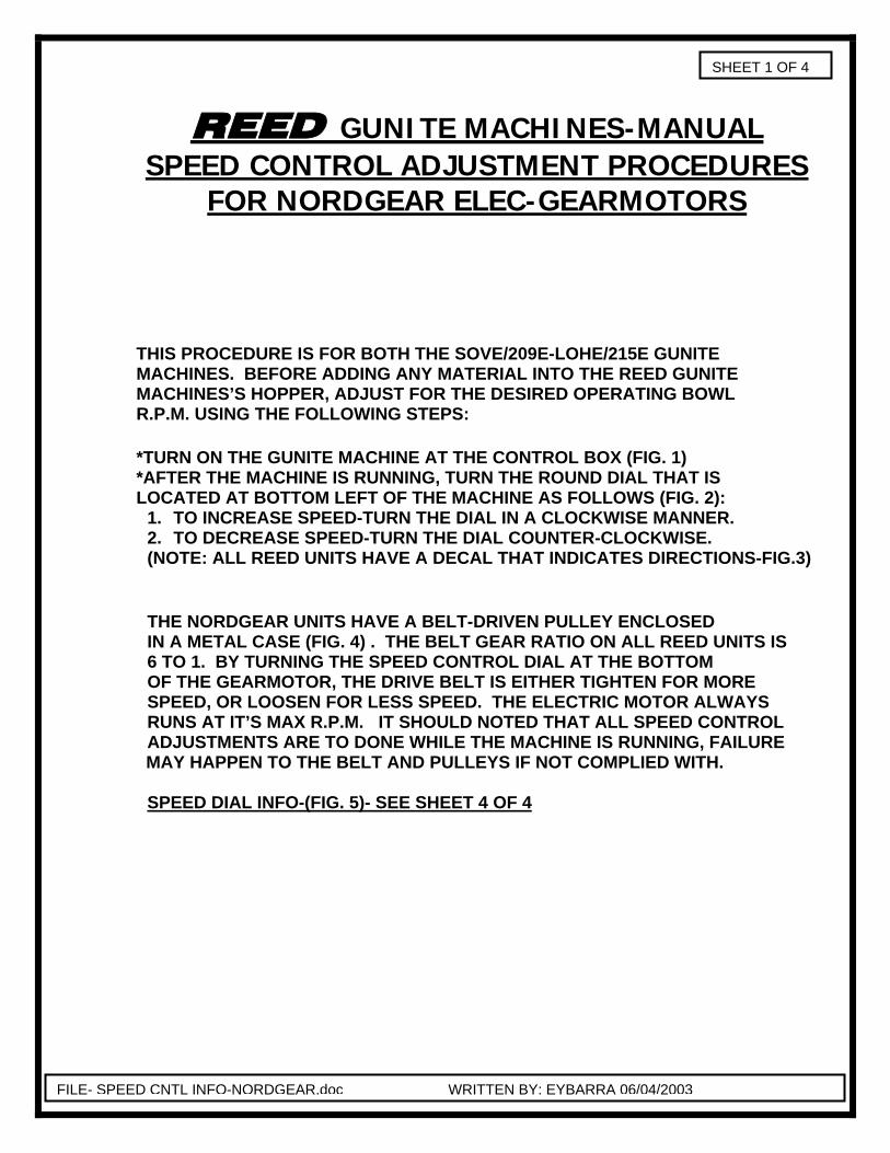
REED GUNITE MACHINES-MANUAL SPEED CONTROL ADJUSTMENT PROCEDURES
FOR NORDGEAR ELEC-GEARMOTORS
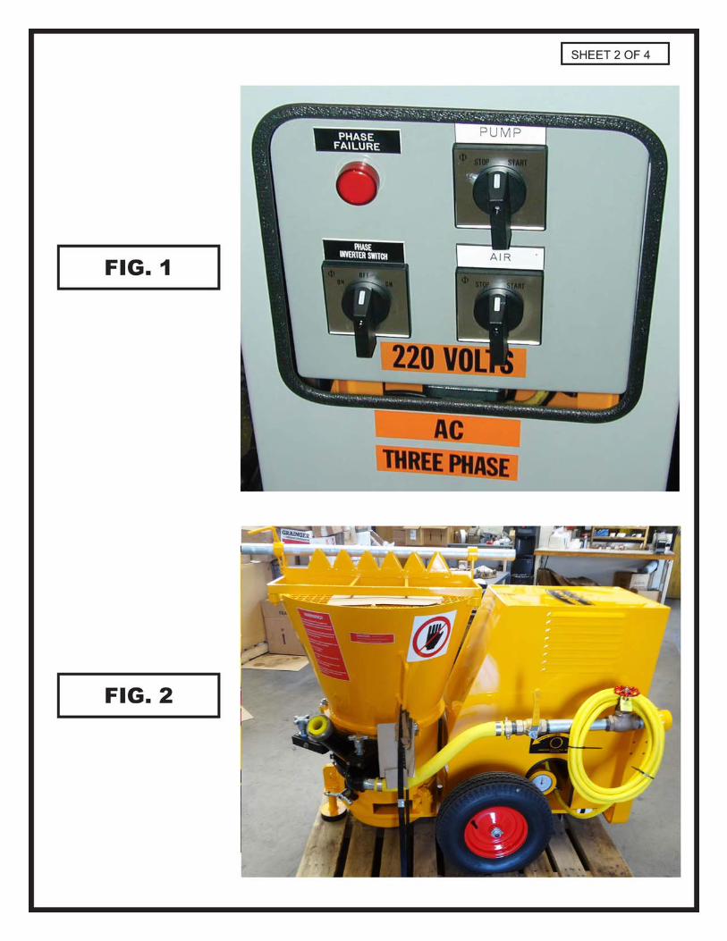
THIS PROCEDURE IS FOR BOTH THE SOVE/209E-LOHE/215E GUNITE MACHINES. BEFORE ADDING ANY MATERIAL INTO THE REED GUNITE MACHINES’S HOPPER, ADJUST FOR THE DESIRED OPERATING BOWL R.P.M. USING THE FOLLOWING STEPS: *TURN ON THE GUNITE MACHINE AT THE CONTROL BOX (FIG. 1) *AFTER THE MACHINE IS RUNNING, TURN THE ROUND DIAL THAT IS LOCATED AT BOTTOM LEFT OF THE MACHINE AS FOLLOWS (FIG. 2):
1. TO INCREASE SPEED-TURN THE DIAL IN A CLOCKWISE MANNER. 2. TO DECREASE SPEED-TURN THE DIAL COUNTER-CLOCKWISE. (NOTE: ALL REED UNITS HAVE A DECAL THAT INDICATES DIRECTIONS-FIG.3) THE NORDGEAR UNITS HAVE A BELT-DRIVEN PULLEY ENCLOSED IN A METAL CASE (FIG. 4) . THE BELT GEAR RATIO ON ALL REED UNITS IS 6 TO 1. BY TURNING THE SPEED CONTROL DIAL AT THE BOTTOM OF THE GEARMOTOR, THE DRIVE BELT IS EITHER TIGHTEN FOR MORE SPEED, OR LOOSEN FOR LESS SPEED. THE ELECTRIC MOTOR ALWAYS RUNS AT IT’S MAX R.P.M. IT SHOULD NOTED THAT ALL SPEED CONTROL ADJUSTMENTS ARE TO DONE WHILE THE MACHINE IS RUNNING, FAILURE
MAY HAPPEN TO THE BELT AND PULLEYS IF NOT COMPLIED WITH. SPEED DIAL INFO-(FIG. 5)- SEE SHEET 4 OF 4
SHEET 1 OF 4
FILE- SPEED CNTL INFO-NORDGEAR.doc WRITTEN BY: EYBARRA 06/04/2003
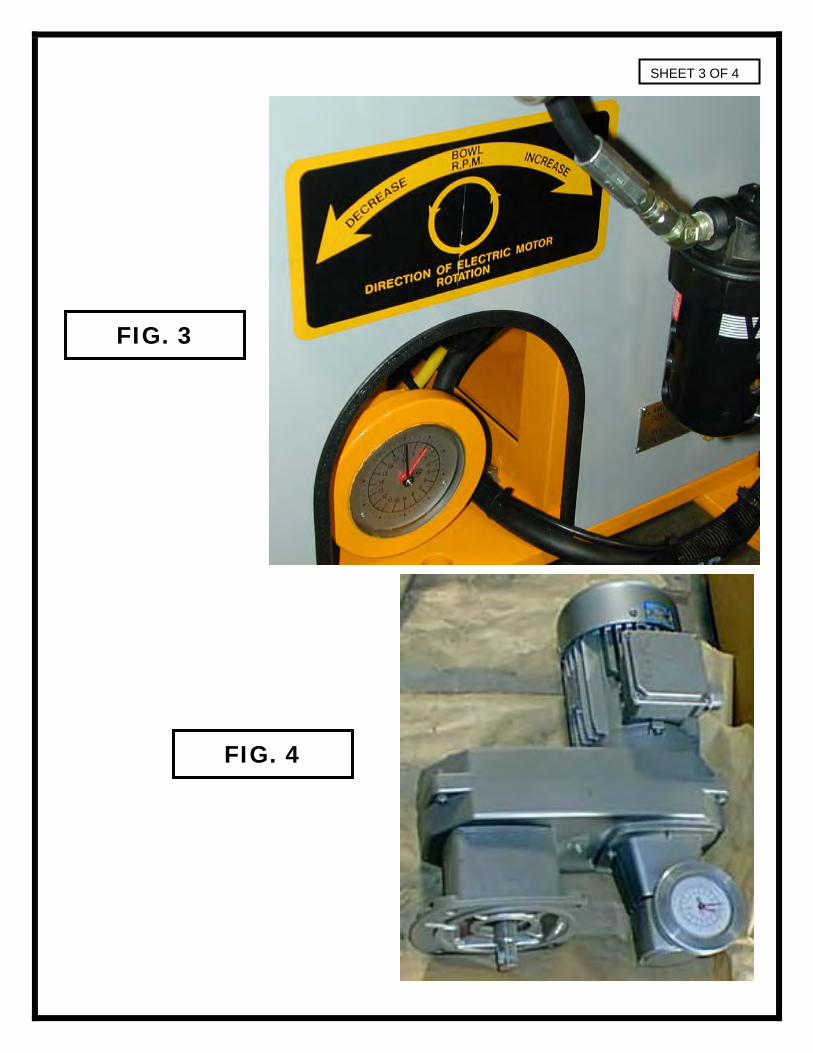
SHEET 3 OF 4
FIG. 3
FIG. 4
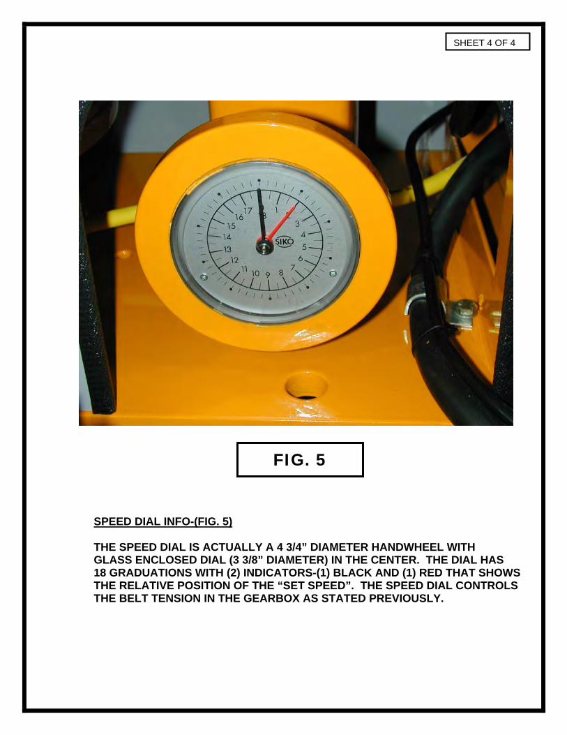
SPEED DIAL INFO-(FIG. 5) THE SPEED DIAL IS ACTUALLY A 4 3/4” DIAMETER HANDWHEEL WITH GLASS ENCLOSED DIAL (3 3/8” DIAMETER) IN THE CENTER. THE DIAL HAS 18 GRADUATIONS WITH (2) INDICATORS-(1) BLACK AND (1) RED THAT SHOWS THE RELATIVE POSITION OF THE “SET SPEED”. THE SPEED DIAL CONTROLS THE BELT TENSION IN THE GEARBOX AS STATED PREVIOUSLY.
SHEET 4 OF 4
FIG. 5
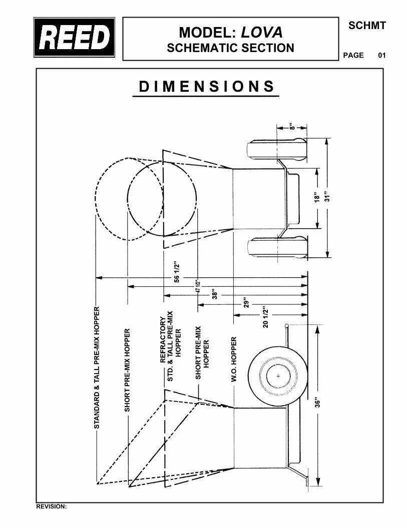
MODEL: LOVASCHEMATIC SECTION
SCHMT
PAGE 01
REVISION: