logicore ip tri-mode ethernet mac v6 - xilinx · the logicore™ ip tri-mode ethernet media access...
TRANSCRIPT

LogiCORE IP Tri-Mode Ethernet MAC v6.0Product Guide for Vivado Design Suite
PG051 March 20, 2013

Tri-Mode Ethernet MAC v6.0 www.xilinx.com 2PG051 March 20, 2013
Table of ContentsIP Facts
Chapter 1: OverviewRecommended Design Experience . . . . . . . . . . . . . . . . . . . . . . . . . . . . . . . . . . . . . . . . . . . . . . . . . . . . 6Ethernet Overview. . . . . . . . . . . . . . . . . . . . . . . . . . . . . . . . . . . . . . . . . . . . . . . . . . . . . . . . . . . . . . . . . 6Core Overview . . . . . . . . . . . . . . . . . . . . . . . . . . . . . . . . . . . . . . . . . . . . . . . . . . . . . . . . . . . . . . . . . . . . 8Feature Summary. . . . . . . . . . . . . . . . . . . . . . . . . . . . . . . . . . . . . . . . . . . . . . . . . . . . . . . . . . . . . . . . . 11Applications . . . . . . . . . . . . . . . . . . . . . . . . . . . . . . . . . . . . . . . . . . . . . . . . . . . . . . . . . . . . . . . . . . . . . 12Licensing and Ordering Information . . . . . . . . . . . . . . . . . . . . . . . . . . . . . . . . . . . . . . . . . . . . . . . . . . 15
Chapter 2: Product SpecificationStandards . . . . . . . . . . . . . . . . . . . . . . . . . . . . . . . . . . . . . . . . . . . . . . . . . . . . . . . . . . . . . . . . . . . . . . . 16Performance. . . . . . . . . . . . . . . . . . . . . . . . . . . . . . . . . . . . . . . . . . . . . . . . . . . . . . . . . . . . . . . . . . . . . 16Resource Utilization. . . . . . . . . . . . . . . . . . . . . . . . . . . . . . . . . . . . . . . . . . . . . . . . . . . . . . . . . . . . . . . 17Port Descriptions . . . . . . . . . . . . . . . . . . . . . . . . . . . . . . . . . . . . . . . . . . . . . . . . . . . . . . . . . . . . . . . . . 19Register Space . . . . . . . . . . . . . . . . . . . . . . . . . . . . . . . . . . . . . . . . . . . . . . . . . . . . . . . . . . . . . . . . . . . 27System Requirements . . . . . . . . . . . . . . . . . . . . . . . . . . . . . . . . . . . . . . . . . . . . . . . . . . . . . . . . . . . . . 56
Chapter 3: Designing with the CoreGeneral Design Guidelines . . . . . . . . . . . . . . . . . . . . . . . . . . . . . . . . . . . . . . . . . . . . . . . . . . . . . . . . . 57Clocking. . . . . . . . . . . . . . . . . . . . . . . . . . . . . . . . . . . . . . . . . . . . . . . . . . . . . . . . . . . . . . . . . . . . . . . . . 60Resets . . . . . . . . . . . . . . . . . . . . . . . . . . . . . . . . . . . . . . . . . . . . . . . . . . . . . . . . . . . . . . . . . . . . . . . . . . 61Protocol Description . . . . . . . . . . . . . . . . . . . . . . . . . . . . . . . . . . . . . . . . . . . . . . . . . . . . . . . . . . . . . . 62AXI4-Stream User Interface. . . . . . . . . . . . . . . . . . . . . . . . . . . . . . . . . . . . . . . . . . . . . . . . . . . . . . . . . 68Flow Control . . . . . . . . . . . . . . . . . . . . . . . . . . . . . . . . . . . . . . . . . . . . . . . . . . . . . . . . . . . . . . . . . . . . . 82Statistics Counters . . . . . . . . . . . . . . . . . . . . . . . . . . . . . . . . . . . . . . . . . . . . . . . . . . . . . . . . . . . . . . . . 89Frame Filter . . . . . . . . . . . . . . . . . . . . . . . . . . . . . . . . . . . . . . . . . . . . . . . . . . . . . . . . . . . . . . . . . . . . . 91Ethernet AVB Endpoint . . . . . . . . . . . . . . . . . . . . . . . . . . . . . . . . . . . . . . . . . . . . . . . . . . . . . . . . . . . . 96Configuration and Status. . . . . . . . . . . . . . . . . . . . . . . . . . . . . . . . . . . . . . . . . . . . . . . . . . . . . . . . . . 111TEMAC Configuration Settings . . . . . . . . . . . . . . . . . . . . . . . . . . . . . . . . . . . . . . . . . . . . . . . . . . . . . 120Physical Interface for the 10 Mb/s and 100 Mb/s Only Ethernet MAC IP Core. . . . . . . . . . . . . . . 121Physical Interfaces for 1 Gb/s Only Ethernet MAC IP Core . . . . . . . . . . . . . . . . . . . . . . . . . . . . . . . 124Physical Interfaces for Tri-Speed (10 Mb/s, 100 Mb/s, and 1 Gb/s) Ethernet MAC IP Core . . . . . 135

Tri-Mode Ethernet MAC v6.0 www.xilinx.com 3PG051 March 20, 2013
Interfacing to Other Xilinx Ethernet Cores . . . . . . . . . . . . . . . . . . . . . . . . . . . . . . . . . . . . . . . . . . . . 148
Chapter 4: Customizing and Generating the CoreVivado Integrated Design Environment (IDE) . . . . . . . . . . . . . . . . . . . . . . . . . . . . . . . . . . . . . . . . . 149Output Generation. . . . . . . . . . . . . . . . . . . . . . . . . . . . . . . . . . . . . . . . . . . . . . . . . . . . . . . . . . . . . . . 153
Chapter 5: Constraining the CoreRequired Constraints . . . . . . . . . . . . . . . . . . . . . . . . . . . . . . . . . . . . . . . . . . . . . . . . . . . . . . . . . . . . . 154Device, Package, and Speed Grade Selections. . . . . . . . . . . . . . . . . . . . . . . . . . . . . . . . . . . . . . . . . 154Clock Frequencies . . . . . . . . . . . . . . . . . . . . . . . . . . . . . . . . . . . . . . . . . . . . . . . . . . . . . . . . . . . . . . . 155I/O Standard and Placement. . . . . . . . . . . . . . . . . . . . . . . . . . . . . . . . . . . . . . . . . . . . . . . . . . . . . . . 155
Chapter 6: Example DesignDetailed Example Design. . . . . . . . . . . . . . . . . . . . . . . . . . . . . . . . . . . . . . . . . . . . . . . . . . . . . . . . . . 158Demonstration Test Bench . . . . . . . . . . . . . . . . . . . . . . . . . . . . . . . . . . . . . . . . . . . . . . . . . . . . . . . . 165Targeting the Example Design to a Board . . . . . . . . . . . . . . . . . . . . . . . . . . . . . . . . . . . . . . . . . . . . 169
Appendix A: Calculating the MMCM Phase Shift or IODelay Tap SettingMMCM Usage. . . . . . . . . . . . . . . . . . . . . . . . . . . . . . . . . . . . . . . . . . . . . . . . . . . . . . . . . . . . . . . . . . . 173IODelay Usage . . . . . . . . . . . . . . . . . . . . . . . . . . . . . . . . . . . . . . . . . . . . . . . . . . . . . . . . . . . . . . . . . . 175
Appendix B: Verification, Compliance, and InteroperabilitySimulation . . . . . . . . . . . . . . . . . . . . . . . . . . . . . . . . . . . . . . . . . . . . . . . . . . . . . . . . . . . . . . . . . . . . . 176Hardware Testing. . . . . . . . . . . . . . . . . . . . . . . . . . . . . . . . . . . . . . . . . . . . . . . . . . . . . . . . . . . . . . . . 176
Appendix C: Migrating to AXI Tri-Mode Ethernet MACHost Interface to AXI4-Lite . . . . . . . . . . . . . . . . . . . . . . . . . . . . . . . . . . . . . . . . . . . . . . . . . . . . . . . . 177Client Interface to AXI4-Stream . . . . . . . . . . . . . . . . . . . . . . . . . . . . . . . . . . . . . . . . . . . . . . . . . . . . 187LocalLink to AXI4-Stream Translation. . . . . . . . . . . . . . . . . . . . . . . . . . . . . . . . . . . . . . . . . . . . . . . . 189
Appendix D: DebuggingFinding Help on Xilinx.com . . . . . . . . . . . . . . . . . . . . . . . . . . . . . . . . . . . . . . . . . . . . . . . . . . . . . . . . 191Debug Tools . . . . . . . . . . . . . . . . . . . . . . . . . . . . . . . . . . . . . . . . . . . . . . . . . . . . . . . . . . . . . . . . . . . . 193Simulation Debug. . . . . . . . . . . . . . . . . . . . . . . . . . . . . . . . . . . . . . . . . . . . . . . . . . . . . . . . . . . . . . . . 194Implementation and Timing Errors. . . . . . . . . . . . . . . . . . . . . . . . . . . . . . . . . . . . . . . . . . . . . . . . . . 196Hardware Debug . . . . . . . . . . . . . . . . . . . . . . . . . . . . . . . . . . . . . . . . . . . . . . . . . . . . . . . . . . . . . . . . 197
Appendix E: Additional ResourcesXilinx Resources . . . . . . . . . . . . . . . . . . . . . . . . . . . . . . . . . . . . . . . . . . . . . . . . . . . . . . . . . . . . . . . . . 200References . . . . . . . . . . . . . . . . . . . . . . . . . . . . . . . . . . . . . . . . . . . . . . . . . . . . . . . . . . . . . . . . . . . . . 200

Tri-Mode Ethernet MAC v6.0 www.xilinx.com 4PG051 March 20, 2013
Revision History . . . . . . . . . . . . . . . . . . . . . . . . . . . . . . . . . . . . . . . . . . . . . . . . . . . . . . . . . . . . . . . . . 201Notice of Disclaimer. . . . . . . . . . . . . . . . . . . . . . . . . . . . . . . . . . . . . . . . . . . . . . . . . . . . . . . . . . . . . . 202
Tri-Mode Ethernet MAC v6.0 www.xilinx.com 5PG051 March 20, 2013 Product Specification
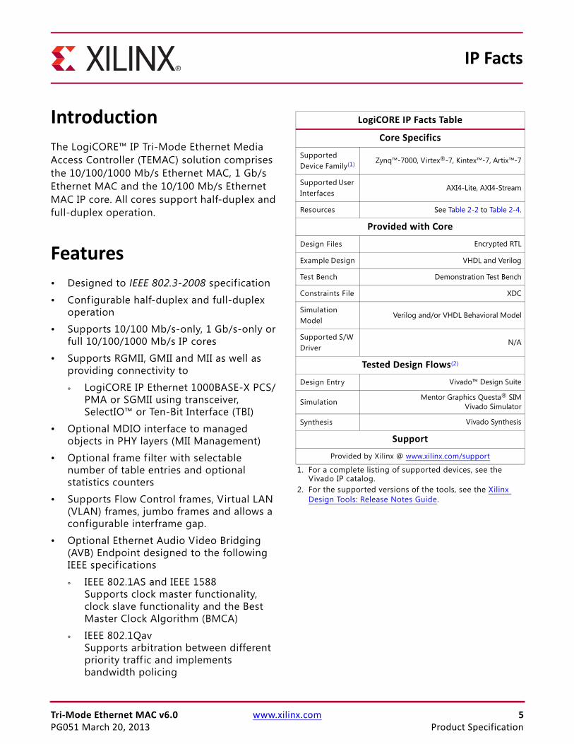
IntroductionThe LogiCORE™ IP Tri-Mode Ethernet Media Access Controller (TEMAC) solution comprises the 10/100/1000 Mb/s Ethernet MAC, 1 Gb/s Ethernet MAC and the 10/100 Mb/s Ethernet MAC IP core. All cores support half-duplex and full-duplex operation.
Features• Designed to IEEE 802.3-2008 specif ication
• Configurable half-duplex and full-duplex operation
• Supports 10/100 Mb/s-only, 1 Gb/s-only or full 10/100/1000 Mb/s IP cores
• Supports RGMII, GMII and MII as well as providing connectivity to
° LogiCORE IP Ethernet 1000BASE-X PCS/PMA or SGMII using transceiver, SelectIO™ or Ten-Bit Interface (TBI)
• Optional MDIO interface to managed objects in PHY layers (MII Management)
• Optional frame filter with selectable number of table entries and optional statistics counters
• Supports Flow Control frames, Virtual LAN (VLAN) frames, jumbo frames and allows a configurable interframe gap.
• Optional Ethernet Audio Video Bridging (AVB) Endpoint designed to the following IEEE specifications
° IEEE 802.1AS and IEEE 1588Supports clock master functionality, clock slave functionality and the Best Master Clock Algorithm (BMCA)
° IEEE 802.1QavSupports arbitration between different priority traff ic and implements bandwidth policing
IP Facts
LogiCORE IP Facts Table
Core Specifics
Supported Device Family(1) Zynq™-7000, Virtex®-7, Kintex™-7, Artix™-7
Supported User Interfaces
AXI4-Lite, AXI4-Stream
Resources See Table 2-2 to Table 2-4.
Provided with Core
Design Files Encrypted RTL
Example Design VHDL and Verilog
Test Bench Demonstration Test Bench
Constraints File XDC
Simulation Model
Verilog and/or VHDL Behavioral Model
Supported S/W Driver
N/A
Tested Design Flows(2)
Design Entry Vivado™ Design Suite
SimulationMentor Graphics Questa® SIM
Vivado Simulator
Synthesis Vivado Synthesis
Support
Provided by Xilinx @ www.xilinx.com/support
1. For a complete listing of supported devices, see the Vivado IP catalog.
2. For the supported versions of the tools, see the Xilinx Design Tools: Release Notes Guide.
Tri-Mode Ethernet MAC v6.0 www.xilinx.com 6PG051 March 20, 2013
Chapter 1
OverviewThe Tri-Mode Ethernet Media Access Controller (TEMAC) solution comprises the 10/100/1000 Mb/s, 1 Gb/s and 10/100 Mb/s IP (Intellectual Property) cores along with the optional Ethernet AVB Endpoint which are fully-verif ied designs. In addition, the example design provided with the core is in both Verilog-HDL and VHDL. This chapter introduces the TEMAC solution and provides related information, including recommended design experience, additional resources, technical support, and submitting feedback to Xilinx.
Recommended Design ExperienceAlthough the TEMAC core is fully-verif ied, the challenge associated with implementing a complete design varies depending on the configuration and functionality of the application. For best results, previous experience building high performance, pipelined FPGA designs using Xilinx implementation software and Constraint Files is recommended. Contact your local Xilinx representative for a closer review and estimation for your specific requirements.
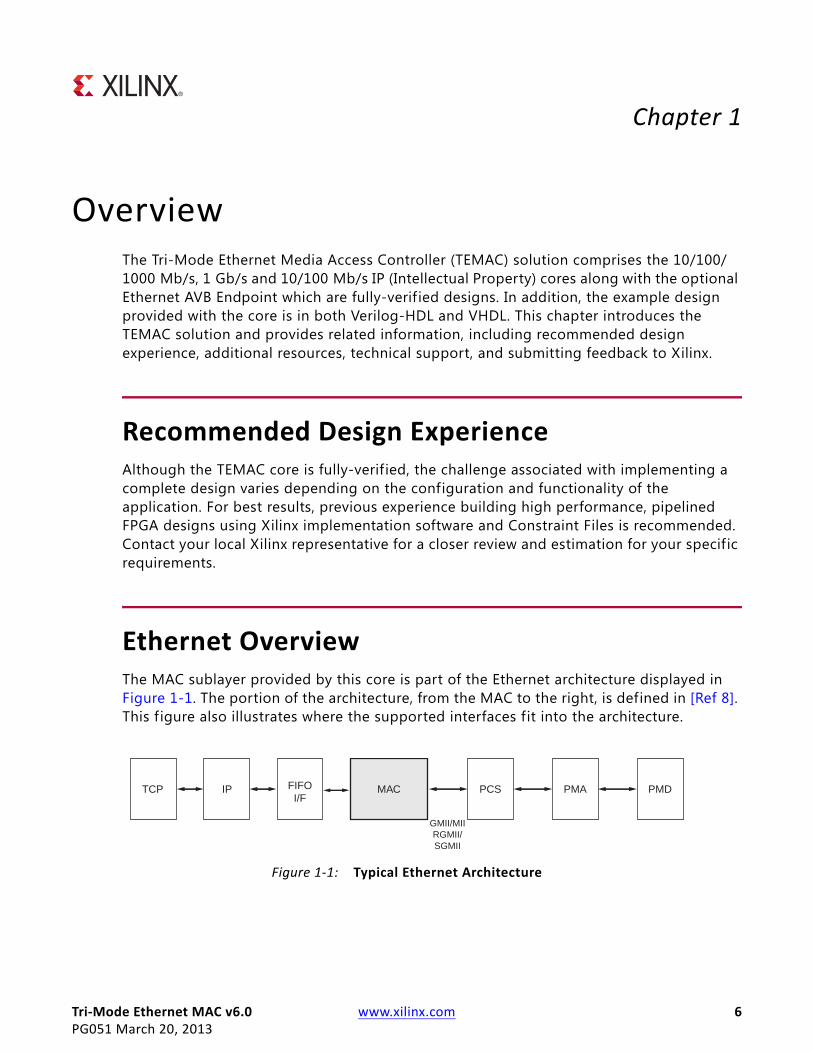
Ethernet OverviewThe MAC sublayer provided by this core is part of the Ethernet architecture displayed in Figure 1-1. The portion of the architecture, from the MAC to the right, is defined in [Ref 8]. This f igure also illustrates where the supported interfaces fit into the architecture.
X-Ref Target - Figure 1-1
Figure 1-1: Typical Ethernet Architecture
TCP IP FIFOI/F
PCSMAC PMA PMD
GMII/MIIRGMII/SGMII
Tri-Mode Ethernet MAC v6.0 www.xilinx.com 7PG051 March 20, 2013
Chapter 1: Overview
MAC
The Ethernet Medium Access Controller (MAC) is defined in [Ref 8] clauses 2, 3, and 4. A MAC is responsible for the Ethernet framing protocols and error detection of these frames. The MAC is independent of, and can be connected to, any type of physical layer.
GMII/MII
The Gigabit Media Independent Interface (GMII) is defined in [Ref 8], clause 35. At 10 Mb/s and 100 Mb/s, the Media Independent Interface (MII) is used as defined in [Ref 8], clause 22. These are parallel interfaces connecting a MAC to the physical sublayers (PCS, PMA, and PMD).
RGMII
The Reduced Gigabit Media Independent Interface (RGMII) is an alternative to the GMII. RGMII achieves a 50-percent reduction in the pin count, compared with GMII, and for this reason is preferred over GMII by PCB designers. This is achieved with the use of double-data-rate (DDR) flip-flops. No change in the operation of the core is required to select between GMII and RGMII. However, the clock management logic and Input/Output Block (IOB) logic around the core does change. HDL example designs are provided with the core which implement either the GMII or RGMII protocols.
SGMII
The Serial-GMII (SGMII) is an alternative interface to the GMII, which converts the parallel interface of the GMII into a serial format, radically reducing the I/O count (and for this reason often favored by PCB designers).
The TEMAC solution can be extended to include SGMII functionality by internally connecting its PHY side GMII to the Ethernet 1000BASE-X PCS/PMA or SGMII core from Xilinx. See Interfacing to Other Xilinx Ethernet Cores in Chapter 3.
PCS, PMA, and PMD
The combination of the Physical Coding Sublayer (PCS), the Physical Medium Attachment (PMA), and the Physical Medium Dependent (PMD) sublayer comprise the physical layers of the Ethernet protocol.
Two main physical standards are specif ied for Ethernet:
• BASE-T, a copper standard using twisted pair cabling systems
• BASE-X, usually a f iber optical physical standard using short and long wavelength laser
BASE-T devices, supporting 10 Mb/s, 100 Mb/s, and 1 Gb/s Ethernet speeds, are readily available as off-the-shelf parts. As illustrated in Figure 1-3, these can be connected using GMII/MII, RGMII, or SGMII to provide a tri-speed Ethernet port.
Tri-Mode Ethernet MAC v6.0 www.xilinx.com 8PG051 March 20, 2013
Chapter 1: Overview
The 1000BASE-X architecture can be provided by connecting the TEMAC core to the Ethernet 1000BASE-X PCS/PMA or SGMII core.
A more in-depth Ethernet Protocol Overview is provided in Chapter 3.
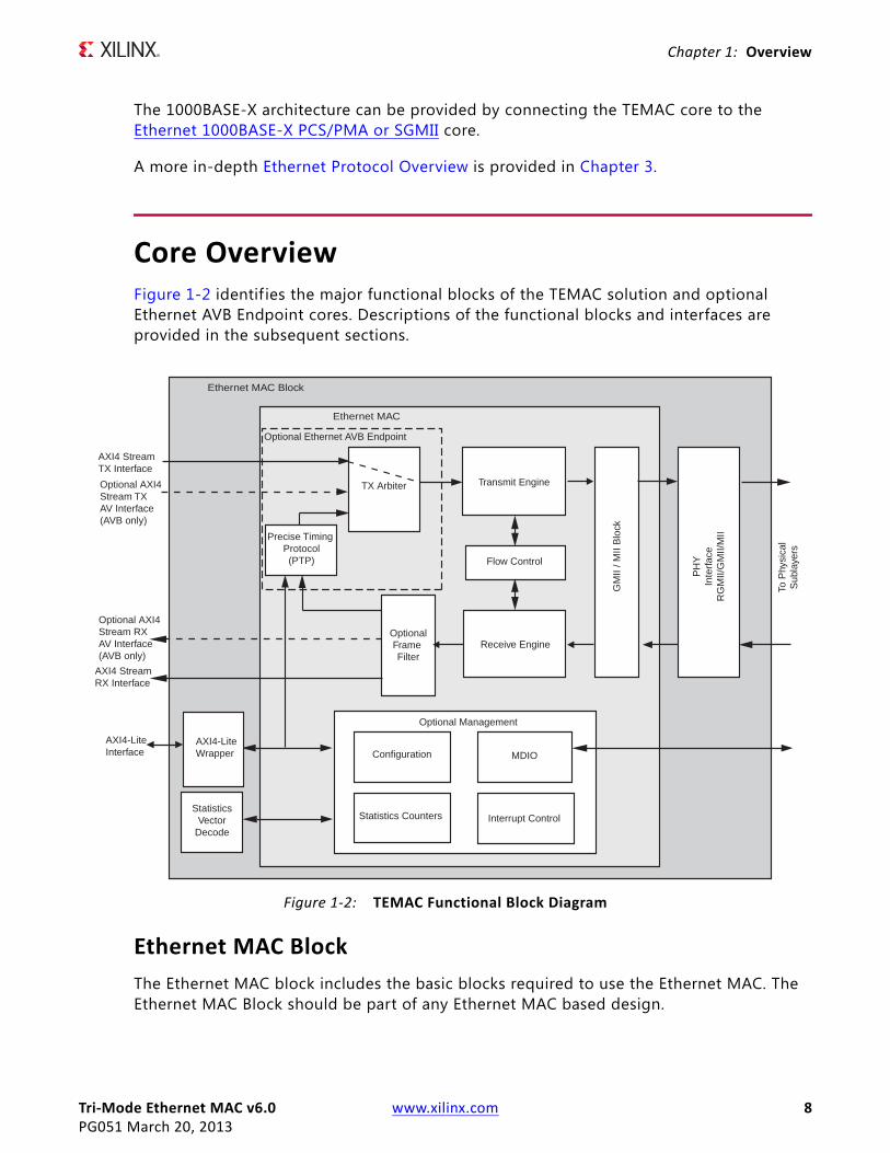
Core OverviewFigure 1-2 identif ies the major functional blocks of the TEMAC solution and optional Ethernet AVB Endpoint cores. Descriptions of the functional blocks and interfaces are provided in the subsequent sections.
Ethernet MAC BlockThe Ethernet MAC block includes the basic blocks required to use the Ethernet MAC. The Ethernet MAC Block should be part of any Ethernet MAC based design.
X-Ref Target - Figure 1-2
Figure 1-2: TEMAC Functional Block Diagram
Flow Control
Transmit Engine
Receive Engine
Configuration
Optional Frame
Filter
MDIO
AXI4 StreamRX Interface
To P
hysi
cal
Sub
laye
rs
GM
II / M
II B
lock
Optional Management
Ethernet MAC
Statistics Counters Interrupt Control
PH
YIn
terf
ace
RG
MII/
GM
II/M
II
Ethernet MAC Block
AXI4-LiteWrapper
StatisticsVector
Decode
AXI4-LiteInterface
AXI4 StreamTX Interface
Precise Timing Protocol(PTP)
Optional AXI4 Stream RX AV Interface(AVB only)
TX ArbiterOptional AXI4 Stream TX AV Interface(AVB only)
Optional Ethernet AVB Endpoint
Tri-Mode Ethernet MAC v6.0 www.xilinx.com 9PG051 March 20, 2013
Chapter 1: Overview
AXI4-Lite WrapperThe AXI4-Lite Wrapper allows the Ethernet MAC to be connected to an AXI4-Lite Interface and drives the Ethernet MAC through a processor independent Intellectual Property Interface (IPIF).
Statistics Vector DecodeThe Statistics Vector Decode interprets the RX and TX statistics vectors supplied by the Ethernet MAC on a per frame basis and generates the Statistics counter increment controls. This code is provided as editable HDL to enable specific Statistics counter requirements to be met.
PHY InterfaceThe PHY Interface provides the required logic to interface to the PHY using either RGMII or GMII/MII. The core can be generated without the PHY Interface to allow direct connection to the LogiCORE™ IP Ethernet 1000BASE-X PCS/PMA or SGMII.
Ethernet AVB EndpointThe TEMAC can be implemented with an optional Ethernet AVB endpoint which itself is made up of two key functional blocks. When this functionality is not included the AXI4-Stream TX Data is passed directly to the transmit engine. The AXI4-Stream RX Data is always passed directly to you, with the relative tuser signals being used to validate the data on the required interface.
Precise Timing Protocol (PTP)
The Precise Timing Protocol (PTP) block within the core provides the dedicated hardware to implement the IEEE 802.1AS specif ication. However, full functionality is only achieved using a combination of this hardware block coupled with functions provided by the relevant software drivers (run on an embedded processor). For more information see Precise Timing Protocol Packet Buffers.
TX Arbiter
Data for transmission over an AVB network can be obtained from three source types:
1. AV Traffic – For transmission from the AV Traffic I/F of the core.
2. Precise Timing Protocol (PTP) Packets – Initiated by the software drivers using the dedicated hardware
3. Legacy Traffic – For transmission from the Legacy Traff ic I/F of the core.

Tri-Mode Ethernet MAC v6.0 www.xilinx.com 10PG051 March 20, 2013
Chapter 1: Overview
The transmitter (TX) arbiter selects from these three sources in the following manner. If there is an AV packet available and the programmed AV bandwidth limitation is not exceeded then the AV packet is transmitted; otherwise the TX arbiter checks to see if there are any PTP packets to be transmitted and if not then it checks to see if there is an available legacy packet to be transmitted. To comply with the specif ications, the AV Traffic Interface should not be configured to exceed 75% of the overall Ethernet bandwidth. The arbiter then polices this bandwidth restriction for the AV traff ic and ensures that on average, it is never exceeded. Consequently, despite the AV traffic having a higher priority than the legacy traffic, there is always remaining bandwidth available to schedule legacy traffic.
Transmit EngineThe transmit engine takes data from the AXI4-Stream TX interface and converts it to GMII format. Preamble and frame check sequence fields are added and the data is padded if necessary. The transmit engine also provides the transmit statistics vector for each packet and transmits the pause frames generated by the flow control module.
Receive EngineThe receive engine takes the data from the GMII/MII interface and checks it for compliance to [Ref 8]. Padding fields are removed and the AXI4-Stream RX interface is presented with the frame data along with a good/bad indication. The receive engine also provides the receive statistics vector for each received packet.
Flow ControlThe flow control block is designed to [Ref 8], clause 31. The MAC can be configured to send pause frames with a programmable pause value and to act on their reception. These two behaviors can be configured asymmetrically.
GMII/MII BlockThe GMII/MII interface, which only operates at speeds below 1 Gb/s, converts between the 4-bit data required by MII and the 8-bit data expected by the Receiver/Transmitter interfaces.
Management InterfaceThe optional Management Interface is a processor-independent interface with standard address, data, and control signals. It is used for the configuration and monitoring of the MAC and for access to the Management Data Input/Output (MDIO) Interface. It is supplied with a wrapper to interface to the industry standard AXI4-Lite. This interface is optional. If it is not present, the device can be configured using configuration vectors.

Tri-Mode Ethernet MAC v6.0 www.xilinx.com 11PG051 March 20, 2013
Chapter 1: Overview
MDIO InterfaceThe optional MDIO interface can be written to and read from using the Management Interface. The MDIO is used to monitor and configure PHY devices. The MDIO Interface is defined in [Ref 8], clause 22.
Frame FilterThe TEMAC solution can be implemented with an optional frame filter. If the frame filter is enabled, the device does not pass frames that do not contain one of a set of known addresses or match against one of the configurable frame filters. By default, all configurable frame filters are initialized to match against the [Ref 8] defined Broadcast Address being observed in the destination address field of the MAC frame.
When the AVB Endpoint is included the frame filter is always present with three filters being dedicated to identifying AV or PTP data. In this case these f ilters are initialized to identify the default values for the various frame fields. The number of f ilters selected by you is in addition to these three.
Statistics CountersThe TEMAC solution can be implemented with optional Statistics Counters. See Statistics Counters for more details.
Feature SummaryThe key features of the TEMAC solution are:
• Designed to the IEEE Std 802.3-2008 specif ication
• Supports four separate IP cores
° 10/100/1000 Mb/s Ethernet MAC
° 1 Gb/s Ethernet MAC
° 10/100 Mb/s Ethernet MAC
° Optional Ethernet AVB
• Configurable duplex operation
• Support for Media Independent Interface (MII), Gigabit Media Independent Interface (GMII), Reduced Gigabit Media Independent Interface (RGMII) and connection to the Ethernet 1000BASE-X PCS/PMA or SGMII LogiCORE.
• Management Data Input/Output (MDIO) interface to manage objects in the physical layer

Tri-Mode Ethernet MAC v6.0 www.xilinx.com 12PG051 March 20, 2013
Chapter 1: Overview
• User-accessible raw statistic vector outputs
• Optional built in statistics counters
• Optional built-in Ethernet AVB Endpoint designed to the following IEEE specifications
° IEEE802.1AS – Supports clock master functionality, clock slave functionality and the Best Master Clock Algorithm (BMCA)
° IEEE802.1Qav – Supports arbitration between different priority traff ic and implements bandwidth policing
• Support for VLAN frames
• Configurable interframe gap (IFG) adjustment in full-duplex operation
• Configurable in-band Frame Check Sequence (FCS) f ield passing on both transmit and receive paths
• Auto padding on transmit and stripping on receive paths
• Optional fully memory mapped AXI4-Lite interface for configuration and monitoring
• Configurable flow control through Ethernet MAC Control PAUSE frames; symmetrically or asymmetrically enabled
• Configurable support for jumbo frames of any length
• Configurable maximum frame length check
• Configurable receive frame filter
• AXI4-Stream user interface for Transmit and Receive frame datapath.
ApplicationsTypical applications for the Ethernet MAC include:
• Ethernet Switch or Router
• Ethernet Communications Port for an Embedded Processor
• Ethernet AVB Endpoint System

Tri-Mode Ethernet MAC v6.0 www.xilinx.com 13PG051 March 20, 2013
Chapter 1: Overview
Ethernet Switch or RouterFigure 1-3 illustrates a typical application for a single Ethernet MAC. The Physical-side interface (PHY) side of the core is connected to an off-the-shelf Ethernet PHY device, which performs the BASE-T standard at 1 Gb/s, 100 Mb/s, and 10 Mb/s speeds. The PHY device can be connected using any of the following supported interfaces: GMII/MII, RGMII, or, by additionally using the Ethernet 1000BASE-X PCS/PMA or SGMII LogiCORE, SGMII.
The user side of the Ethernet MAC is connected to a FIFO to complete a single Ethernet port. This port is connected to a Switch or Routing matrix, which can contain several ports.
The TEMAC solution is provided with an example design for any of the supported physical interfaces. A FIFO example is also generated, which can be used as the FIFO in the illustration, for a typical application.
Ethernet Communications Port for an Embedded ProcessorFigure 1-4 illustrates a typical application for a single Ethernet MAC. The PHY side of the core is connected to an off-the-shelf Ethernet PHY device, which performs the BASE-T standard at 1 Gb/s, 100 Mb/s, and 10 Mb/s speeds. The PHY device can be connected using any of the following supported interfaces: GMII/MII, RGMII, or, by additionally using the Ethernet 1000BASE-X PCS/PMA or SGMII LogiCORE, SGMII.
The user side of the MAC is connected to a processor system through a processor DMA engine. This processor could be running a communications stack, such as the Transmission Control Protocol/Internet Protocol (TCP/IP). For applications such as this, see the Xilinx Platform Studio (XPS), Embedded Development Kit (EDK) IP portfolio. This portfolio contains additional IP to connect the user interface of the MAC to the DMA port of a processor. [Ref 11] describes the AXI Ethernet, which can be instantiated for an intended processor application.
X-Ref Target - Figure 1-3
Figure 1-3: Typical Application: Ethernet Switch or Router
Copper Medium
GMII/MII,RGMII,
or SGMII
Ethernet MACIOBs
Tri-SpeedBASE-T
PHY
Xilinx FPGA Device
Ethernet MAC Block
Packet FIFOSwitch or
Router
1 Gb/s,100 Mb/s,
or10 Mb/s
Tri-Mode Ethernet MAC v6.0 www.xilinx.com 14PG051 March 20, 2013
Chapter 1: Overview
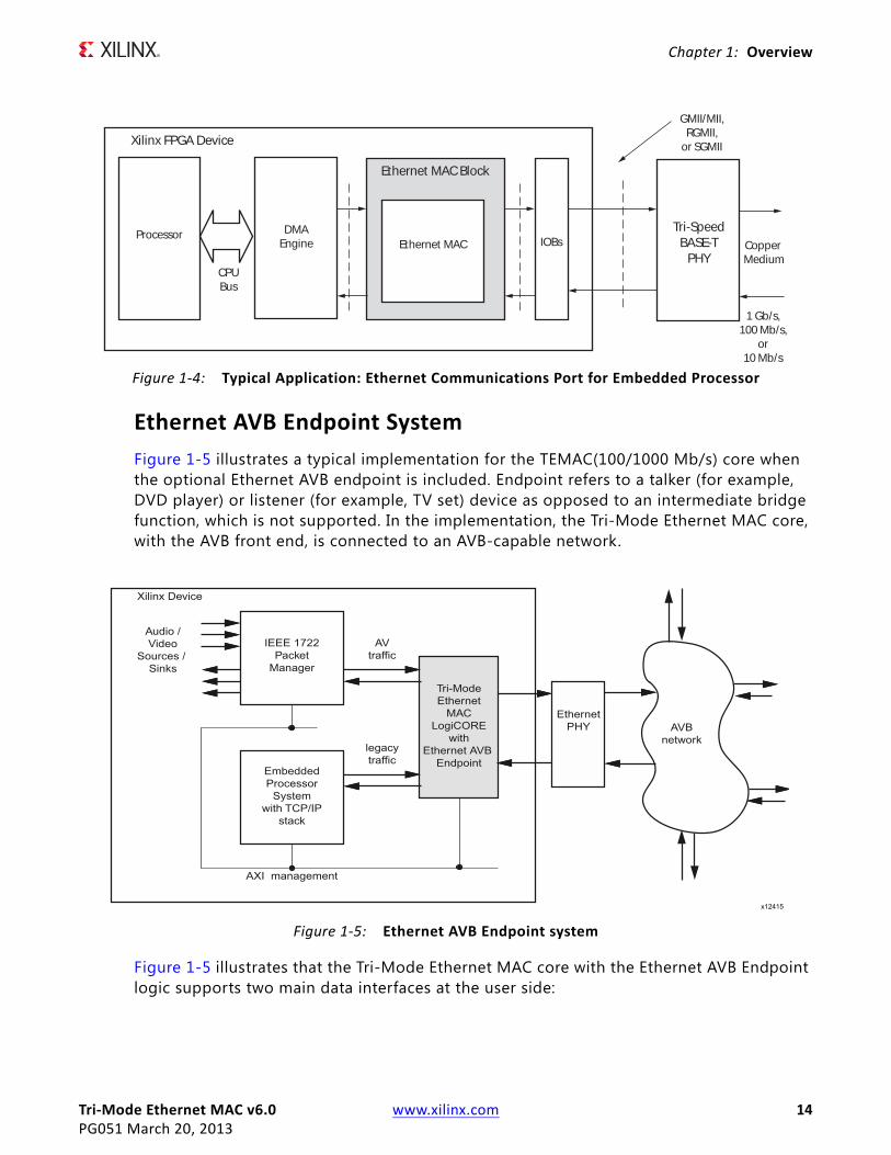
Ethernet AVB Endpoint SystemFigure 1-5 illustrates a typical implementation for the TEMAC(100/1000 Mb/s) core when the optional Ethernet AVB endpoint is included. Endpoint refers to a talker (for example, DVD player) or listener (for example, TV set) device as opposed to an intermediate bridge function, which is not supported. In the implementation, the Tri-Mode Ethernet MAC core, with the AVB front end, is connected to an AVB-capable network.
Figure 1-5 illustrates that the Tri-Mode Ethernet MAC core with the Ethernet AVB Endpoint logic supports two main data interfaces at the user side:
X-Ref Target - Figure 1-4
Figure 1-4: Typical Application: Ethernet Communications Port for Embedded Processor
Copper Medium
GMII/MII,RGMII,
or SGMII
Ethernet MAC IOBsTri-Speed
BASE-TPHY
Xilinx FPGA Device
Ethernet MAC Block
DMAEngine
1 Gb/s,100 Mb/s,
or10 Mb/s
Processor
CPUBus
X-Ref Target - Figure 1-5
Figure 1-5: Ethernet AVB Endpoint system
Tri-Mode Ethernet MAC v6.0 www.xilinx.com 15PG051 March 20, 2013
Chapter 1: Overview
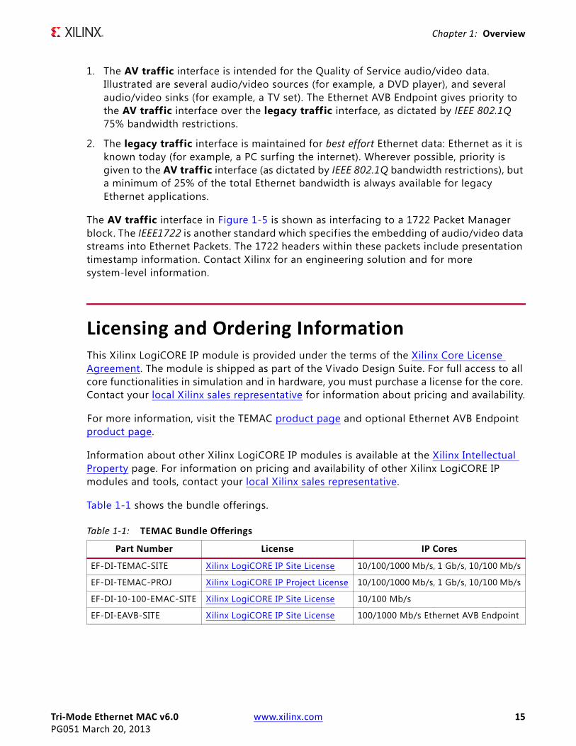
1. The AV traffic interface is intended for the Quality of Service audio/video data. Illustrated are several audio/video sources (for example, a DVD player), and several audio/video sinks (for example, a TV set). The Ethernet AVB Endpoint gives priority to the AV traffic interface over the legacy traffic interface, as dictated by IEEE 802.1Q 75% bandwidth restrictions.
2. The legacy traffic interface is maintained for best effort Ethernet data: Ethernet as it is known today (for example, a PC surf ing the internet). Wherever possible, priority is given to the AV traffic interface (as dictated by IEEE 802.1Q bandwidth restrictions), but a minimum of 25% of the total Ethernet bandwidth is always available for legacy Ethernet applications.
The AV traffic interface in Figure 1-5 is shown as interfacing to a 1722 Packet Manager block. The IEEE1722 is another standard which specif ies the embedding of audio/video data streams into Ethernet Packets. The 1722 headers within these packets include presentation timestamp information. Contact Xilinx for an engineering solution and for more system-level information.
Licensing and Ordering InformationThis Xilinx LogiCORE IP module is provided under the terms of the Xilinx Core License Agreement. The module is shipped as part of the Vivado Design Suite. For full access to all core functionalities in simulation and in hardware, you must purchase a license for the core. Contact your local Xilinx sales representative for information about pricing and availability.
For more information, visit the TEMAC product page and optional Ethernet AVB Endpoint product page.
Information about other Xilinx LogiCORE IP modules is available at the Xilinx Intellectual Property page. For information on pricing and availability of other Xilinx LogiCORE IP modules and tools, contact your local Xilinx sales representative.
Table 1-1 shows the bundle offerings.
Table 1-1: TEMAC Bundle Offerings
Part Number License IP Cores
EF-DI-TEMAC-SITE Xilinx LogiCORE IP Site License 10/100/1000 Mb/s, 1 Gb/s, 10/100 Mb/s
EF-DI-TEMAC-PROJ Xilinx LogiCORE IP Project License 10/100/1000 Mb/s, 1 Gb/s, 10/100 Mb/s
EF-DI-10-100-EMAC-SITE Xilinx LogiCORE IP Site License 10/100 Mb/s
EF-DI-EAVB-SITE Xilinx LogiCORE IP Site License 100/1000 Mb/s Ethernet AVB Endpoint

Tri-Mode Ethernet MAC v6.0 www.xilinx.com 16PG051 March 20, 2013
Chapter 2
Product SpecificationThe TEMAC solution is generated through the Xilinx Vivado™ Design Suite included in the latest IP Update on the Xilinx IP Center. For detailed information about the core, see the TEMAC product page and the Ethernet AVB Endpoint product page for that optional feature.
StandardsThe System Core adheres to the AMBA® AXI4 Interface standard [Ref 12].
Designed to IEEE 802.3-2008 specification.
Performance
LatencyThe latency figures given in the following sections apply to all permutations of the core.
Transmit Path Latency
The transmit path latency is measured by counting the number of valid cycles between a data byte being placed on the user interface (tx_axis_mac_tdata), and it appearing at the GMII/MII output (gmii_txd) of the Ethernet MAC core level. So latency values do not include any GMII/MII or RGMII logic within the example design. Transmitter path latency has been measured as:
• 8 clock-enabled cycles at 1 Gb/s Ethernet speed.
• 7 or 7.5 clock-enabled cycles at 10 Mb/s and 100 Mb/s Ethernet speeds. This extra half cycle of uncertainty is due to the conversion of 8-bit user data to 4-bit MII width conversion: data is presented to the MII at the earliest possible opportunity.

Tri-Mode Ethernet MAC v6.0 www.xilinx.com 17PG051 March 20, 2013
Chapter 2: Product Specification
Receive Path Latency
The receive path latency is measured as the number of valid cycles between a byte being driven onto the GMII/MII receive interface (gmii_rxd), and it appearing at the user interface (rx_axis_mac_tdata) of the Ethernet MAC core level. So latency values do not include any GMII/MII or RGMII logic within the example design. Receiver path latency has been measured as:
• 15 clock-enabled cycles at 1 Gb/s Ethernet speed.
• 15 or 15.5 clock-enabled cycles at 10 Mb/s and 100 Mb/s Ethernet speeds. This extra half cycle of uncertainty is due to the conversion of 4-bit MII data width to 8-bit user data conversion.
Resource Utilization
Supported Families
Device UtilizationTables 2-2 to Table 2-4 provide approximate utilization f igures for various core options when a single instance of the core is instantiated in a Virtex®-7 device.
Utilization f igures are obtained by implementing the block level wrapper for the core.
Table 2-2 does not differentiate between 10/100/1000 Mb/s support and 1 Gb/s only support or GMII, MII and RGMII Physical Interfaces. The numbers quoted are for GMII10/100/1000 Mb/s support; 1 Gb/s only support Slice, lookup table (LUT) and flip-flop (FF) f igures are slightly reduced.
Table 2-1: Interface Support by Device Family
Virtex-7 Kintex-7 Artix-7 Zynq010/020 Zynq030/045
MII Yes(3)(2) Yes(1)(2) Yes Yes Yes(1)(2)
GMII Yes(3)(2) Yes(1)(2) Yes Yes Yes(1)(2)
RGMIIv2.0 Yes(3)(2) Yes(1)(2) Yes Yes Yes(1)(2)
Notes: 1. HRIO supports MII/GMII at 3.3V or lower and RGMII at 2.5V or lower. See the relevant FPGA Data Sheet
for I/O availability.2. For HPIO only 1.8V or lower is supported. An external voltage converter is required to interface to
any PHY requiring 2.5V or above. 3. HRIO, available in limited parts, supports MII/GMII at 3.3V or lower and RGMII at 2.5V or lower. See the
relevant FPGA Data Sheet for I/O availability.
Tri-Mode Ethernet MAC v6.0 www.xilinx.com 18PG051 March 20, 2013
Chapter 2: Product Specification
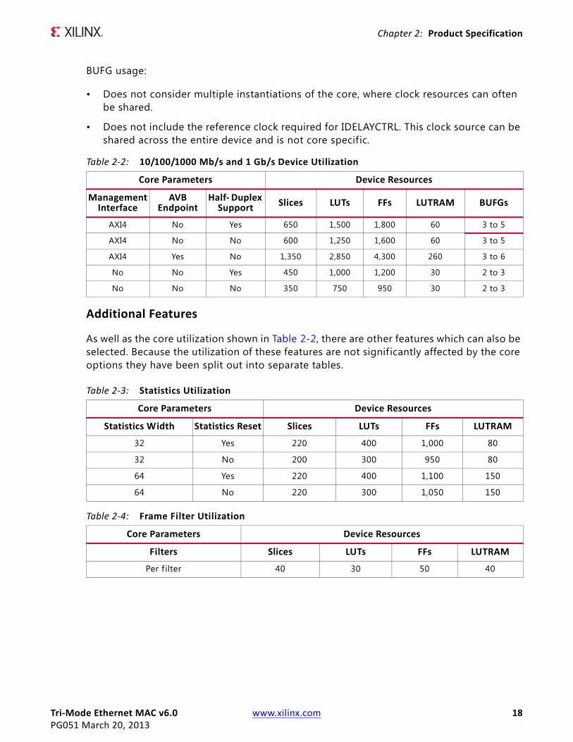
BUFG usage:
• Does not consider multiple instantiations of the core, where clock resources can often be shared.
• Does not include the reference clock required for IDELAYCTRL. This clock source can be shared across the entire device and is not core specific.
Additional Features
As well as the core utilization shown in Table 2-2, there are other features which can also be selected. Because the utilization of these features are not signif icantly affected by the core options they have been split out into separate tables.
Table 2-2: 10/100/1000 Mb/s and 1 Gb/s Device Utilization
Core Parameters Device Resources
ManagementInterface
AVB Endpoint
Half- Duplex Support Slices LUTs FFs LUTRAM BUFGs
AXI4 No Yes 650 1,500 1,800 60 3 to 5
AXI4 No No 600 1,250 1,600 60 3 to 5
AXI4 Yes No 1,350 2,850 4,300 260 3 to 6
No No Yes 450 1,000 1,200 30 2 to 3
No No No 350 750 950 30 2 to 3
Table 2-3: Statistics Utilization
Core Parameters Device Resources
Statistics Width Statistics Reset Slices LUTs FFs LUTRAM
32 Yes 220 400 1,000 80
32 No 200 300 950 80
64 Yes 220 400 1,100 150
64 No 220 300 1,050 150
Table 2-4: Frame Filter Utilization
Core Parameters Device Resources
Filters Slices LUTs FFs LUTRAM
Per f ilter 40 30 50 40

Tri-Mode Ethernet MAC v6.0 www.xilinx.com 19PG051 March 20, 2013
Chapter 2: Product Specification
Port DescriptionsAll ports of the Ethernet MAC core level are internal connections in the Field Programmable Gate Array (FPGA) logic. An example HDL design, provided in both VHDL and Verilog, is delivered with each core. The example design connects the core to a FIFO-based loopback example design and adds Input/Output Block (IOB) flip-flops to the external signals of the GMII/MII (or RGMII).
All clock management logic translated from a single on-board clock to the required system clocks are placed in this example design, allowing you more flexibility in implementation (for example, in designs using multiple cores). For information about the example design, see Chapter 6, Example Design.
User Interfaces
Transmitter Interface
Table 2-5 defines the AXI4-Stream transmit signals of the core, which are used to transmit data from the user to the core. Table 2-6 defines transmit sideband signals. A detailed description of operation is provided in Transmitting Outbound Frames in Chapter 3.
Table 2-5: Transmit Interface AXI4-Stream Signal Pins
Signal Direction Clock Domain Description
tx_axis_mac_tdata[7:0] Input tx_mac_aclk Frame data to be transmitted.
tx_axis_mac_tvalid Input tx_mac_aclk Control signal for tx_axis_mac_tdata port. Indicates the data is valid.
tx_axis_mac_tlast Input tx_mac_aclk Control signal for tx_axis_mac_tdata port. Indicates the f inal transfer in a frame.
tx_axis_mac_tuser Input tx_mac_aclk Control signal for tx_axis_mac_tdata port. Indicates an error condition, such as FIFO underrun, in the frame allowing the MAC to send an error to the PHY.
tx_axis_mac_tready Output tx_mac_aclk Handshaking signal. Asserted when the current data on tx_axis_mac_tdata has been accepted and tx_axis_mac_tvalid is high. At 10/100 Mb/s this is used to meter the data into the core at the correct rate.
Note: All signals are active-High.

Tri-Mode Ethernet MAC v6.0 www.xilinx.com 20PG051 March 20, 2013
Chapter 2: Product Specification
Table 2-7 defines the optional AXI4-Stream AV transmit signals included when the AVB functionality is selected.
Table 2-6: Transmit Interface Sideband Signal Pins
Signal Direction Clock Domain Description
tx_ifg_delay[7:0] Input tx_mac_aclk Control signal for configurable interframe gap
tx_collision Output tx_mac_aclk Asserted by the Ethernet MAC core level to signal a collision on the medium and that any transmission in progress should be aborted. Always 0 when the Ethernet MAC core level is in full-duplex mode.
tx_retransmit Output tx_mac_aclk When asserted at the same time as the tx_collision signal, this signals to the client that the aborted frame should be resupplied to the Ethernet MAC core level for retransmission. Always 0 when the Ethernet MAC core level is in full-duplex mode.
tx_statisitics_vector[31:0] Output tx_mac_aclk A statistics vector that gives information on the last frame transmitted.
tx_statistics_valid Output tx_mac_aclk Asserted at end of frame transmission, indicating that the tx_statistics_vector is valid.
Note: All signals are active-High.
Table 2-7: Transmit Interface AXI4-Stream AV Signal Pins
Signal Direction Clock Domain Description
tx_axis_av_tdata[7:0] Input tx_mac_aclk Frame data to be transmitted.
tx_axis_av_tvalid Input tx_mac_aclk Control signal for tx_axis_av_tdata port. Indicates the data is valid.
tx_axis_av_tlast Input tx_mac_aclk Control signal for tx_axis_av_tdata port. Indicates the f inal transfer in a frame.
tx_axis_av_tuser Input tx_mac_aclk Control signal for tx_axis_av_tdata port. Indicates an error condition, such as FIFO underrun, in the frame allowing the MAC to send an error to the PHY.
tx_axis_av_tready Output tx_mac_aclk Handshaking signal. Asserted when the current data on tx_axis_av_tdata has been accepted and tx_axis_av_tvalid is high. At 100 Mb/s this is used to meter the data into the core at the correct rate.
Note: All signals are active-High.
Tri-Mode Ethernet MAC v6.0 www.xilinx.com 21PG051 March 20, 2013
Chapter 2: Product Specification
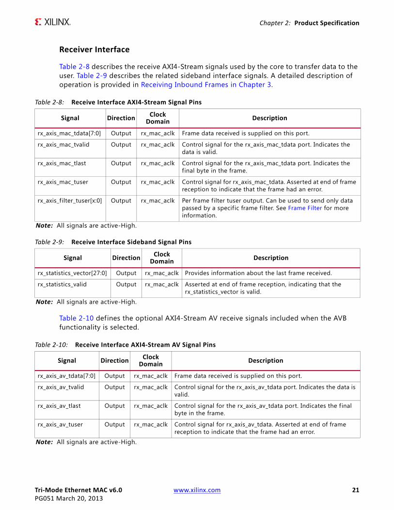
Receiver Interface
Table 2-8 describes the receive AXI4-Stream signals used by the core to transfer data to the user. Table 2-9 describes the related sideband interface signals. A detailed description of operation is provided in Receiving Inbound Frames in Chapter 3.
Table 2-10 defines the optional AXI4-Stream AV receive signals included when the AVB functionality is selected.
Table 2-8: Receive Interface AXI4-Stream Signal Pins
Signal Direction ClockDomain Description
rx_axis_mac_tdata[7:0] Output rx_mac_aclk Frame data received is supplied on this port.
rx_axis_mac_tvalid Output rx_mac_aclk Control signal for the rx_axis_mac_tdata port. Indicates the data is valid.
rx_axis_mac_tlast Output rx_mac_aclk Control signal for the rx_axis_mac_tdata port. Indicates the final byte in the frame.
rx_axis_mac_tuser Output rx_mac_aclk Control signal for rx_axis_mac_tdata. Asserted at end of frame reception to indicate that the frame had an error.
rx_axis_filter_tuser[x:0] Output rx_mac_aclk Per frame f ilter tuser output. Can be used to send only data passed by a specific frame filter. See Frame Filter for more information.
Note: All signals are active-High.
Table 2-9: Receive Interface Sideband Signal Pins
Signal Direction ClockDomain Description
rx_statistics_vector[27:0] Output rx_mac_aclk Provides information about the last frame received.
rx_statistics_valid Output rx_mac_aclk Asserted at end of frame reception, indicating that the rx_statistics_vector is valid.
Note: All signals are active-High.
Table 2-10: Receive Interface AXI4-Stream AV Signal Pins
Signal Direction ClockDomain Description
rx_axis_av_tdata[7:0] Output rx_mac_aclk Frame data received is supplied on this port.
rx_axis_av_tvalid Output rx_mac_aclk Control signal for the rx_axis_av_tdata port. Indicates the data is valid.
rx_axis_av_tlast Output rx_mac_aclk Control signal for the rx_axis_av_tdata port. Indicates the f inal byte in the frame.
rx_axis_av_tuser Output rx_mac_aclk Control signal for rx_axis_av_tdata. Asserted at end of frame reception to indicate that the frame had an error.
Note: All signals are active-High.
Tri-Mode Ethernet MAC v6.0 www.xilinx.com 22PG051 March 20, 2013
Chapter 2: Product Specification
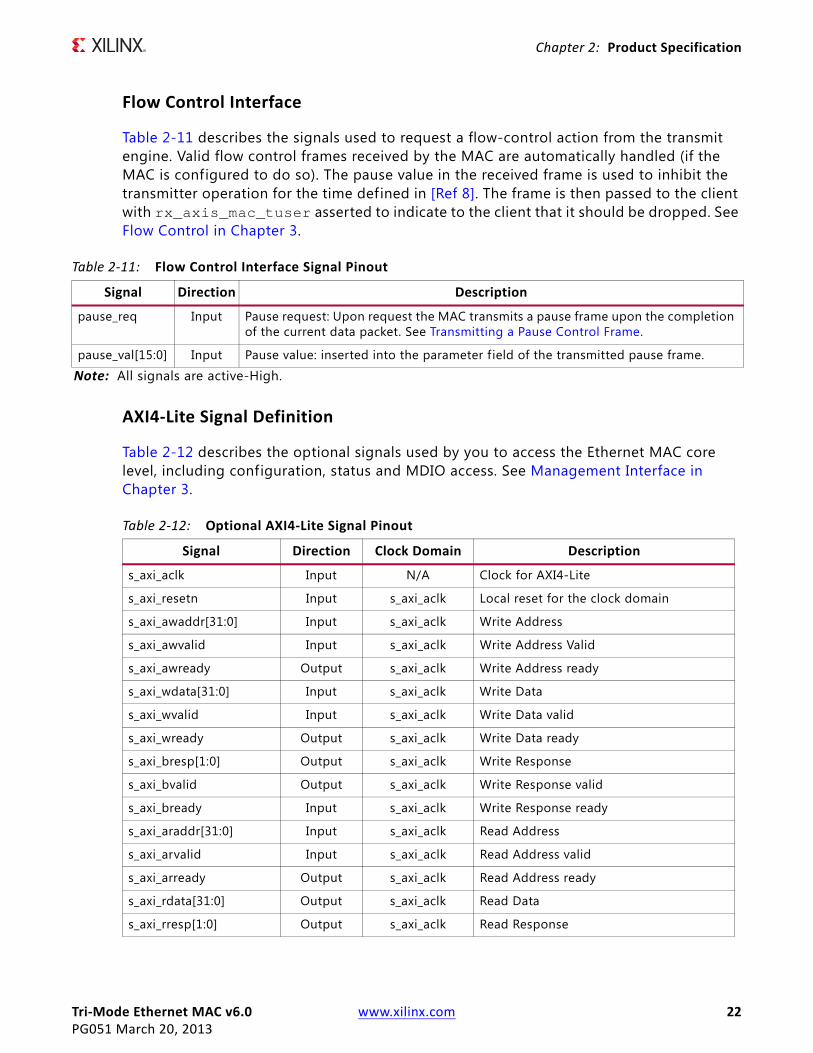
Flow Control Interface
Table 2-11 describes the signals used to request a flow-control action from the transmit engine. Valid flow control frames received by the MAC are automatically handled (if the MAC is configured to do so). The pause value in the received frame is used to inhibit the transmitter operation for the time defined in [Ref 8]. The frame is then passed to the client with rx_axis_mac_tuser asserted to indicate to the client that it should be dropped. See Flow Control in Chapter 3.
AXI4-Lite Signal Definition
Table 2-12 describes the optional signals used by you to access the Ethernet MAC core level, including configuration, status and MDIO access. See Management Interface in Chapter 3.
Table 2-11: Flow Control Interface Signal Pinout
Signal Direction Description
pause_req Input Pause request: Upon request the MAC transmits a pause frame upon the completion of the current data packet. See Transmitting a Pause Control Frame.
pause_val[15:0] Input Pause value: inserted into the parameter field of the transmitted pause frame.
Note: All signals are active-High.
Table 2-12: Optional AXI4-Lite Signal Pinout
Signal Direction Clock Domain Description
s_axi_aclk Input N/A Clock for AXI4-Lite
s_axi_resetn Input s_axi_aclk Local reset for the clock domain
s_axi_awaddr[31:0] Input s_axi_aclk Write Address
s_axi_awvalid Input s_axi_aclk Write Address Valid
s_axi_awready Output s_axi_aclk Write Address ready
s_axi_wdata[31:0] Input s_axi_aclk Write Data
s_axi_wvalid Input s_axi_aclk Write Data valid
s_axi_wready Output s_axi_aclk Write Data ready
s_axi_bresp[1:0] Output s_axi_aclk Write Response
s_axi_bvalid Output s_axi_aclk Write Response valid
s_axi_bready Input s_axi_aclk Write Response ready
s_axi_araddr[31:0] Input s_axi_aclk Read Address
s_axi_arvalid Input s_axi_aclk Read Address valid
s_axi_arready Output s_axi_aclk Read Address ready
s_axi_rdata[31:0] Output s_axi_aclk Read Data
s_axi_rresp[1:0] Output s_axi_aclk Read Response
Tri-Mode Ethernet MAC v6.0 www.xilinx.com 23PG051 March 20, 2013
Chapter 2: Product Specification
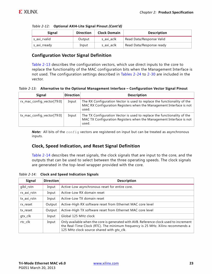
Configuration Vector Signal Definition
Table 2-13 describes the configuration vectors, which use direct inputs to the core to replace the functionality of the MAC configuration bits when the Management Interface is not used. The configuration settings described in Tables 2-24 to 2-30 are included in the vector.
Note: All bits of the config vectors are registered on input but can be treated as asynchronous inputs.
Clock, Speed Indication, and Reset Signal Definition
Table 2-14 describes the reset signals, the clock signals that are input to the core, and the outputs that can be used to select between the three operating speeds. The clock signals are generated in the top-level wrapper provided with the core.
s_axi_rvalid Output s_axi_aclk Read Data/Response Valid
s_axi_rready Input s_axi_aclk Read Data/Response ready
Table 2-12: Optional AXI4-Lite Signal Pinout (Cont’d)
Signal Direction Clock Domain Description
Table 2-13: Alternative to the Optional Management Interface – Configuration Vector Signal Pinout
Signal Direction Description
rx_mac_config_vector[79:0] Input The RX Configuration Vector is used to replace the functionality of the MAC RX Configuration Registers when the Management Interface is not used.
tx_mac_config_vector[79:0] Input The TX Configuration Vector is used to replace the functionality of the MAC TX Configuration Registers when the Management Interface is not used.
Table 2-14: Clock and Speed Indication Signals
Signal Direction Descriptionglbl_rstn Input Active-Low asynchronous reset for entire core.
rx_axi_rstn Input Active-Low RX domain reset
tx_axi_rstn Input Active-Low TX domain reset
rx_reset Output Active-High RX software reset from Ethernet MAC core level
tx_reset Output Active-High TX software reset from Ethernet MAC core level
gtx_clk Input Global 125 MHz clock
rtc_clk Input Only available when the core is generated with AVB. Reference clock used to increment the Real-Time Clock (RTC). The minimum frequency is 25 MHz. Xilinx recommends a 125 MHz clock source shared with gtx_clk.

Tri-Mode Ethernet MAC v6.0 www.xilinx.com 24PG051 March 20, 2013
Chapter 2: Product Specification
Interrupt Signals
Table 2-15 describes the interrupt signals provided by the TEMAC core.
tx_mac_aclk Input Clock for the transmission of data on the physical interface. 125 MHz at 1 Gb/s, 25 MHz at 100 Mb/s, and 2.5 MHz at 10 Mb/s. This clock should be used to clock the physical interface transmit circuitry and the TX AXI4-Stream transmit circuitry. This clock only exists in GMII or MII. See the appropriate section:• Physical Interface for the 10 Mb/s and 100 Mb/s Only Ethernet MAC IP Core• Physical Interfaces for 1 Gb/s Only Ethernet MAC IP Core• Physical Interfaces for Tri-Speed (10 Mb/s, 100 Mb/s, and 1 Gb/s) Ethernet MAC IP
Core
rx_mac_aclk Input Clock for the reception of data on the physical interface. 125 MHz at 1 Gb/s, 25 MHz at 100 Mb/s, and 2.5 MHz at 10 Mb/s. This clock should be used to clock the physical interface receive circuitry and the RX AXI4-Stream receive circuitry. See the appropriate section:• Physical Interface for the 10 Mb/s and 100 Mb/s Only Ethernet MAC IP Core• Physical Interfaces for 1 Gb/s Only Ethernet MAC IP Core• Physical Interfaces for Tri-Speed (10 Mb/s, 100 Mb/s, and 1 Gb/s) Ethernet MAC IP
Core
speedis100 Output This output is asserted when the core is operating at 100 Mb/s. It is derived from either Bits[31:30] of the MAC Speed Configuration register. If the optional Management Interface is not present, this is derived from configuration vector Bits[66:65].
speedis10100 Output This output is asserted when the core is operating at either 10 Mb/s or 100 Mb/s. It is derived from either Bits[31:30] of the MAC Speed Configuration register. If the Management Interface is not present, this is derived from configuration vector Bits[66:65].
Table 2-14: Clock and Speed Indication Signals (Cont’d)
Signal Direction Description
Table 2-15: Interrupt Signals
Signal Direction Descriptionmac_int Output This is the interrupt output from the interrupt controller. Currently the only
interrupt source which can be configured is the mdio_ready signal. See Interrupt Controller for more information.
interrupt_ptp_rx Output Only available when the core is generated with AVB. This is asserted following the reception of any PTP packet by the RX PTP Packet Buffers. See RX PTP Packet Buffer for more information.
interrupt_ptp_tx Output Only available when the core is generated with AVB. This is asserted following the transmission of any PTP packet from the TX PTP Packet Buffers. See TX PTP Packet Buffer for more information.
interrupt_ptp_timer Output Only available when the core is generated with AVB. This interrupt asserts every 1/128 seconds as measured by the RTC. This acts as a timer for the PTP software algorithms. See Real-Time Clock for more information.
Tri-Mode Ethernet MAC v6.0 www.xilinx.com 25PG051 March 20, 2013
Chapter 2: Product Specification
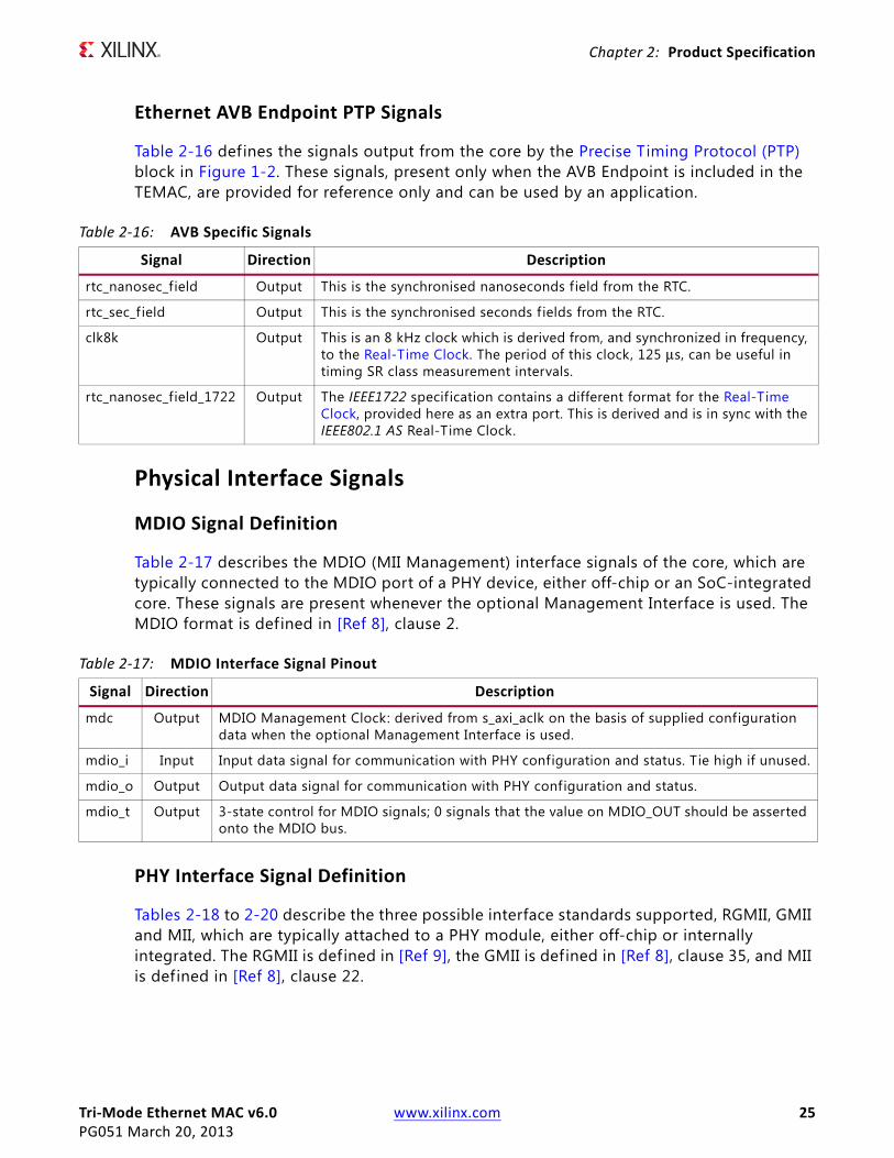
Ethernet AVB Endpoint PTP Signals
Table 2-16 defines the signals output from the core by the Precise Timing Protocol (PTP) block in Figure 1-2. These signals, present only when the AVB Endpoint is included in the TEMAC, are provided for reference only and can be used by an application.
Physical Interface Signals
MDIO Signal Definition
Table 2-17 describes the MDIO (MII Management) interface signals of the core, which are typically connected to the MDIO port of a PHY device, either off-chip or an SoC-integrated core. These signals are present whenever the optional Management Interface is used. The MDIO format is defined in [Ref 8], clause 2.
PHY Interface Signal Definition
Tables 2-18 to 2-20 describe the three possible interface standards supported, RGMII, GMII and MII, which are typically attached to a PHY module, either off-chip or internally integrated. The RGMII is defined in [Ref 9], the GMII is defined in [Ref 8], clause 35, and MII is defined in [Ref 8], clause 22.
Table 2-16: AVB Specific Signals
Signal Direction Description
rtc_nanosec_field Output This is the synchronised nanoseconds field from the RTC.
rtc_sec_field Output This is the synchronised seconds f ields from the RTC.
clk8k Output This is an 8 kHz clock which is derived from, and synchronized in frequency, to the Real-Time Clock. The period of this clock, 125 μs, can be useful in timing SR class measurement intervals.
rtc_nanosec_field_1722 Output The IEEE1722 specification contains a different format for the Real-Time Clock, provided here as an extra port. This is derived and is in sync with the IEEE802.1 AS Real-Time Clock.
Table 2-17: MDIO Interface Signal Pinout
Signal Direction Description
mdc Output MDIO Management Clock: derived from s_axi_aclk on the basis of supplied configuration data when the optional Management Interface is used.
mdio_i Input Input data signal for communication with PHY configuration and status. Tie high if unused.
mdio_o Output Output data signal for communication with PHY configuration and status.
mdio_t Output 3-state control for MDIO signals; 0 signals that the value on MDIO_OUT should be asserted onto the MDIO bus.

Tri-Mode Ethernet MAC v6.0 www.xilinx.com 26PG051 March 20, 2013
Chapter 2: Product Specification
.
Table 2-18: Optional GMII Interface Signal Pinout
Signal Direction Clock Domain Description
gmii_txd[7:0] Output tx_mac_aclk Transmit data to PHY
gmii_tx_en Output tx_mac_aclk Data Enable control signal to PHY
gmii_tx_er Output tx_mac_aclk Error control signal to PHY
mii_tx_clk Input – Clock from PHY (used for 10/100)
gmii_col Input N/A Control signal from PHY
gmii_crs Input N/A Control signal from PHY
gmii_rxd[7:0] Input gmii_rx_clk Received data from PHY
gmii_rx_dv Input gmii_rx_clk Data Valid control signal from PHY
gmii_rx_er Input gmii_rx_clk Error control signal from PHY
gmii_rx_clk Input – Clock from PHY
Table 2-19: Optional MII Interface Signal Pinout
Signal Direction Clock Domain Description
mii_tx_clk Input – Clock from PHY
mii_txd[3:0] Output mii_tx_clk Transmit data to PHY
mii_tx_en Output mii_tx_clk Data Enable control signal to PHY
mii_tx_er Output mii_tx_clk Error control signal to PHY
mii_col Input N/A Control signal from PHY
mii_crs Input N/A Control signal from PHY
mii_rxd[3:0] Input rx_mac_aclk Received data from PHY
mii_rx_dv Input rx_mac_aclk Data Valid control signal from PHY
mii_rx_er Input rx_mac_aclk Error control signal from PHY
mii_rx_clk Input – Clock from PHY
Table 2-20: Optional RGMII Interface Signal Pinout
Signal Direction Clock Domain Description
rgmii_txd[3:0] Output tx_mac_aclk Transmit data to PHY
rgmii_tx_ctl Output tx_mac_aclk control signal to PHY
rgmii_txc Output – Clock to PHY
rgmii_rxd[3:0] Input rgmii_rxc Received data from PHY
rgmii_rx_ctl Input rgmii_rxc Control signal from PHY
rgmii_rxc Input – Clock from PHY
inband_link_status Output rgmii_rxc Link Status from the PHY
inband_clock_speed Output rgmii_rxc Link Speed from the PHY
inband_duplex_status Output rgmii_rxc Duplex Status from the PHY
Tri-Mode Ethernet MAC v6.0 www.xilinx.com 27PG051 March 20, 2013
Chapter 2: Product Specification
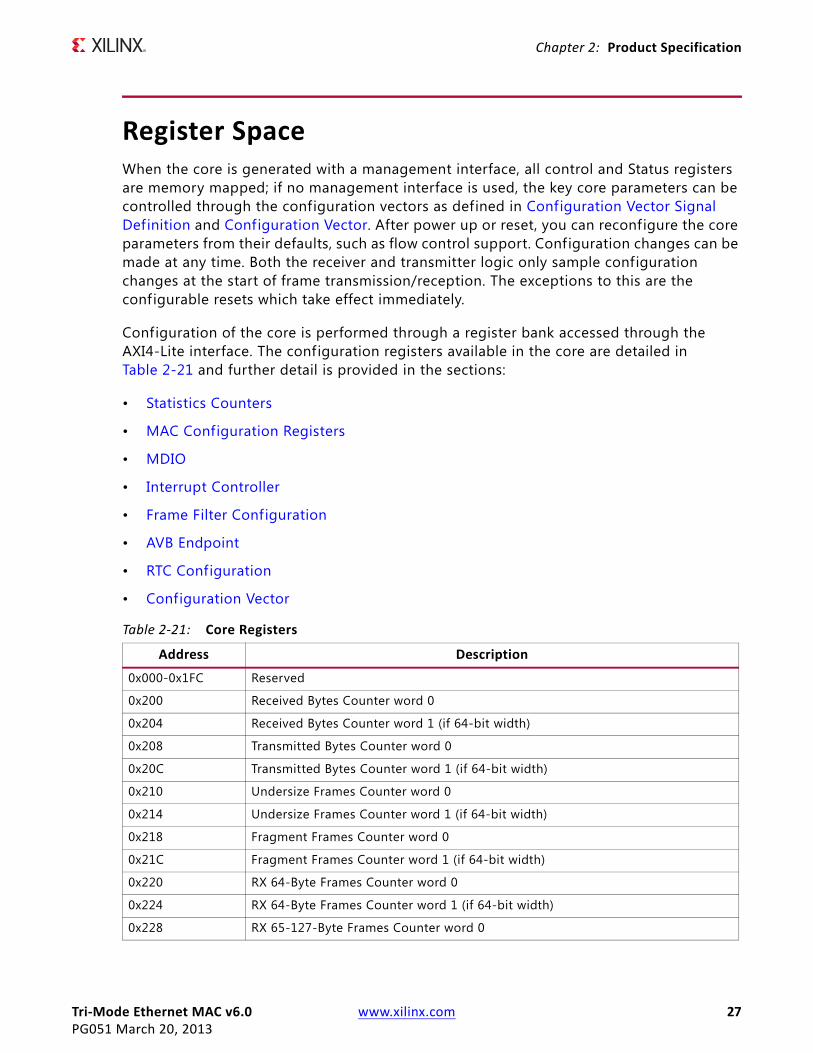
Register SpaceWhen the core is generated with a management interface, all control and Status registers are memory mapped; if no management interface is used, the key core parameters can be controlled through the configuration vectors as defined in Configuration Vector Signal Definition and Configuration Vector. After power up or reset, you can reconfigure the core parameters from their defaults, such as flow control support. Configuration changes can be made at any time. Both the receiver and transmitter logic only sample configuration changes at the start of frame transmission/reception. The exceptions to this are the configurable resets which take effect immediately.
Configuration of the core is performed through a register bank accessed through the AXI4-Lite interface. The configuration registers available in the core are detailed in Table 2-21 and further detail is provided in the sections:
• Statistics Counters
• MAC Configuration Registers
• MDIO
• Interrupt Controller
• Frame Filter Configuration
• AVB Endpoint
• RTC Configuration
• Configuration Vector
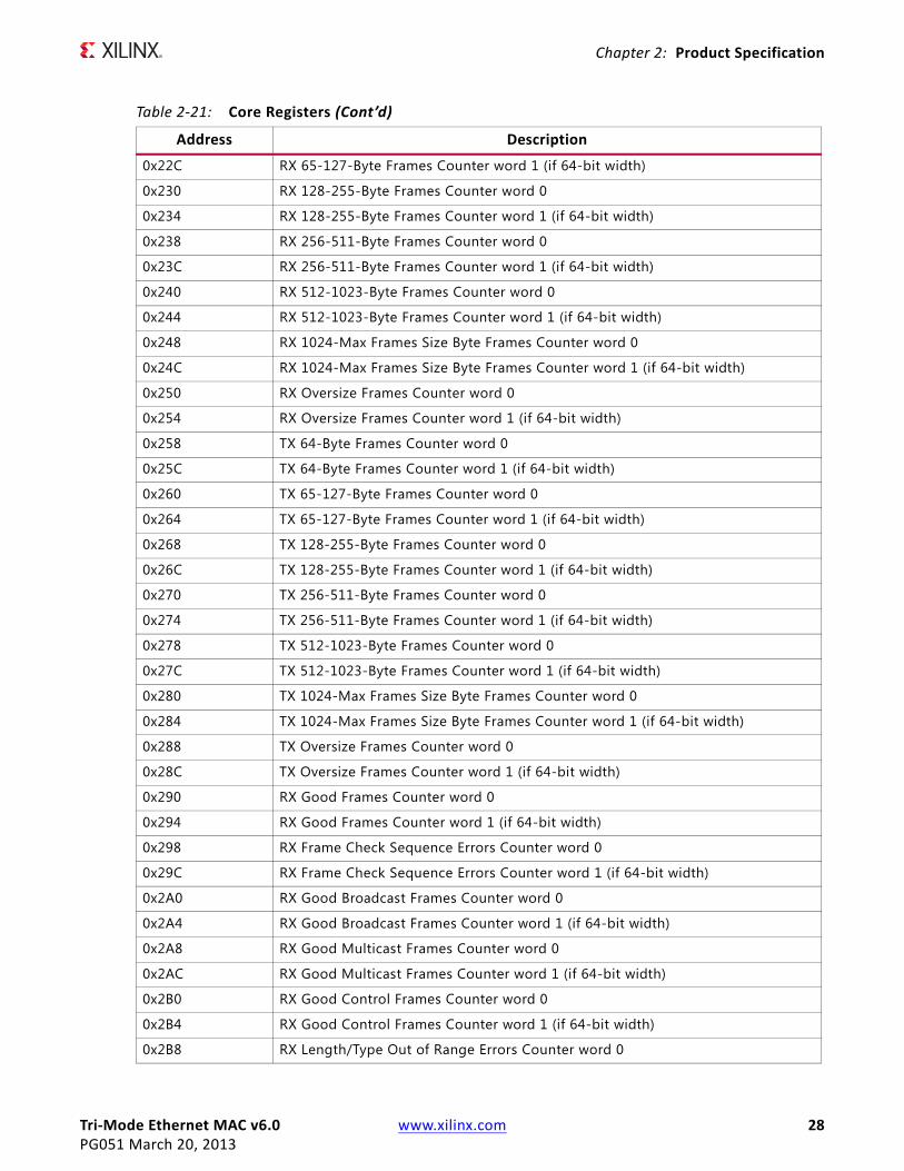
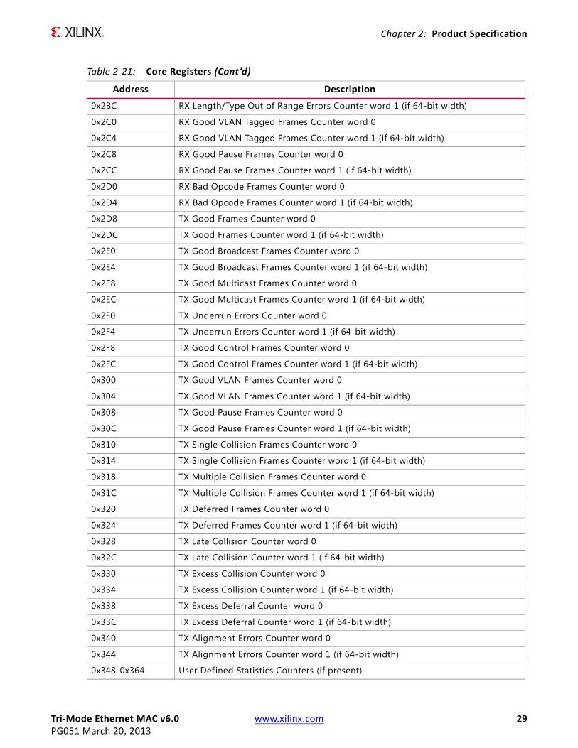
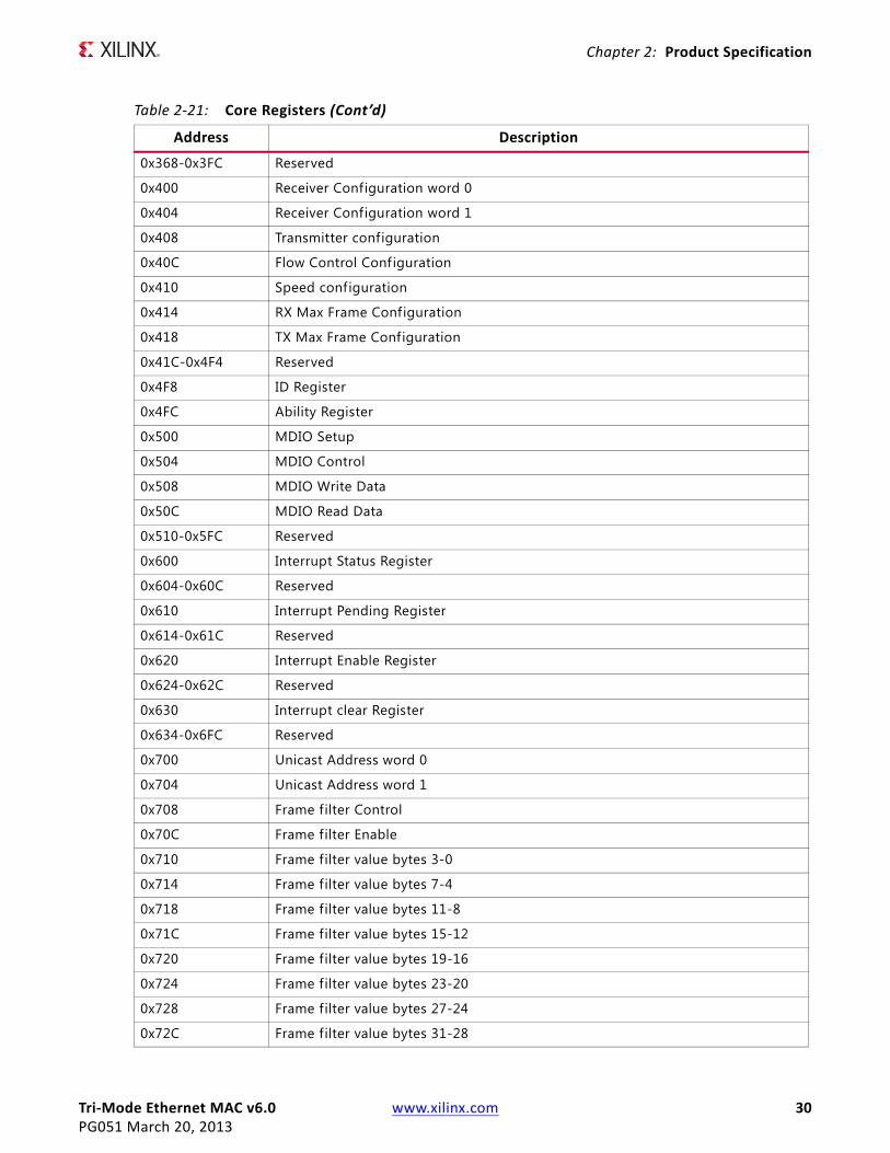
Table 2-21: Core Registers
Address Description
0x000-0x1FC Reserved
0x200 Received Bytes Counter word 0
0x204 Received Bytes Counter word 1 (if 64-bit width)
0x208 Transmitted Bytes Counter word 0
0x20C Transmitted Bytes Counter word 1 (if 64-bit width)
0x210 Undersize Frames Counter word 0
0x214 Undersize Frames Counter word 1 (if 64-bit width)
0x218 Fragment Frames Counter word 0
0x21C Fragment Frames Counter word 1 (if 64-bit width)
0x220 RX 64-Byte Frames Counter word 0
0x224 RX 64-Byte Frames Counter word 1 (if 64-bit width)
0x228 RX 65-127-Byte Frames Counter word 0
Tri-Mode Ethernet MAC v6.0 www.xilinx.com 28PG051 March 20, 2013
Chapter 2: Product Specification
0x22C RX 65-127-Byte Frames Counter word 1 (if 64-bit width)
0x230 RX 128-255-Byte Frames Counter word 0
0x234 RX 128-255-Byte Frames Counter word 1 (if 64-bit width)
0x238 RX 256-511-Byte Frames Counter word 0
0x23C RX 256-511-Byte Frames Counter word 1 (if 64-bit width)
0x240 RX 512-1023-Byte Frames Counter word 0
0x244 RX 512-1023-Byte Frames Counter word 1 (if 64-bit width)
0x248 RX 1024-Max Frames Size Byte Frames Counter word 0
0x24C RX 1024-Max Frames Size Byte Frames Counter word 1 (if 64-bit width)
0x250 RX Oversize Frames Counter word 0
0x254 RX Oversize Frames Counter word 1 (if 64-bit width)
0x258 TX 64-Byte Frames Counter word 0
0x25C TX 64-Byte Frames Counter word 1 (if 64-bit width)
0x260 TX 65-127-Byte Frames Counter word 0
0x264 TX 65-127-Byte Frames Counter word 1 (if 64-bit width)
0x268 TX 128-255-Byte Frames Counter word 0
0x26C TX 128-255-Byte Frames Counter word 1 (if 64-bit width)
0x270 TX 256-511-Byte Frames Counter word 0
0x274 TX 256-511-Byte Frames Counter word 1 (if 64-bit width)
0x278 TX 512-1023-Byte Frames Counter word 0
0x27C TX 512-1023-Byte Frames Counter word 1 (if 64-bit width)
0x280 TX 1024-Max Frames Size Byte Frames Counter word 0
0x284 TX 1024-Max Frames Size Byte Frames Counter word 1 (if 64-bit width)
0x288 TX Oversize Frames Counter word 0
0x28C TX Oversize Frames Counter word 1 (if 64-bit width)
0x290 RX Good Frames Counter word 0
0x294 RX Good Frames Counter word 1 (if 64-bit width)
0x298 RX Frame Check Sequence Errors Counter word 0
0x29C RX Frame Check Sequence Errors Counter word 1 (if 64-bit width)
0x2A0 RX Good Broadcast Frames Counter word 0
0x2A4 RX Good Broadcast Frames Counter word 1 (if 64-bit width)
0x2A8 RX Good Multicast Frames Counter word 0
0x2AC RX Good Multicast Frames Counter word 1 (if 64-bit width)
0x2B0 RX Good Control Frames Counter word 0
0x2B4 RX Good Control Frames Counter word 1 (if 64-bit width)
0x2B8 RX Length/Type Out of Range Errors Counter word 0
Table 2-21: Core Registers (Cont’d)
Address Description
Tri-Mode Ethernet MAC v6.0 www.xilinx.com 29PG051 March 20, 2013
Chapter 2: Product Specification
0x2BC RX Length/Type Out of Range Errors Counter word 1 (if 64-bit width)
0x2C0 RX Good VLAN Tagged Frames Counter word 0
0x2C4 RX Good VLAN Tagged Frames Counter word 1 (if 64-bit width)
0x2C8 RX Good Pause Frames Counter word 0
0x2CC RX Good Pause Frames Counter word 1 (if 64-bit width)
0x2D0 RX Bad Opcode Frames Counter word 0
0x2D4 RX Bad Opcode Frames Counter word 1 (if 64-bit width)
0x2D8 TX Good Frames Counter word 0
0x2DC TX Good Frames Counter word 1 (if 64-bit width)
0x2E0 TX Good Broadcast Frames Counter word 0
0x2E4 TX Good Broadcast Frames Counter word 1 (if 64-bit width)
0x2E8 TX Good Multicast Frames Counter word 0
0x2EC TX Good Multicast Frames Counter word 1 (if 64-bit width)
0x2F0 TX Underrun Errors Counter word 0
0x2F4 TX Underrun Errors Counter word 1 (if 64-bit width)
0x2F8 TX Good Control Frames Counter word 0
0x2FC TX Good Control Frames Counter word 1 (if 64-bit width)
0x300 TX Good VLAN Frames Counter word 0
0x304 TX Good VLAN Frames Counter word 1 (if 64-bit width)
0x308 TX Good Pause Frames Counter word 0
0x30C TX Good Pause Frames Counter word 1 (if 64-bit width)
0x310 TX Single Collision Frames Counter word 0
0x314 TX Single Collision Frames Counter word 1 (if 64-bit width)
0x318 TX Multiple Collision Frames Counter word 0
0x31C TX Multiple Collision Frames Counter word 1 (if 64-bit width)
0x320 TX Deferred Frames Counter word 0
0x324 TX Deferred Frames Counter word 1 (if 64-bit width)
0x328 TX Late Collision Counter word 0
0x32C TX Late Collision Counter word 1 (if 64-bit width)
0x330 TX Excess Collision Counter word 0
0x334 TX Excess Collision Counter word 1 (if 64-bit width)
0x338 TX Excess Deferral Counter word 0
0x33C TX Excess Deferral Counter word 1 (if 64-bit width)
0x340 TX Alignment Errors Counter word 0
0x344 TX Alignment Errors Counter word 1 (if 64-bit width)
0x348-0x364 User Defined Statistics Counters (if present)
Table 2-21: Core Registers (Cont’d)
Address Description
Tri-Mode Ethernet MAC v6.0 www.xilinx.com 30PG051 March 20, 2013
Chapter 2: Product Specification
0x368-0x3FC Reserved
0x400 Receiver Configuration word 0
0x404 Receiver Configuration word 1
0x408 Transmitter configuration
0x40C Flow Control Configuration
0x410 Speed configuration
0x414 RX Max Frame Configuration
0x418 TX Max Frame Configuration
0x41C-0x4F4 Reserved
0x4F8 ID Register
0x4FC Ability Register
0x500 MDIO Setup
0x504 MDIO Control
0x508 MDIO Write Data
0x50C MDIO Read Data
0x510-0x5FC Reserved
0x600 Interrupt Status Register
0x604-0x60C Reserved
0x610 Interrupt Pending Register
0x614-0x61C Reserved
0x620 Interrupt Enable Register
0x624-0x62C Reserved
0x630 Interrupt clear Register
0x634-0x6FC Reserved
0x700 Unicast Address word 0
0x704 Unicast Address word 1
0x708 Frame filter Control
0x70C Frame filter Enable
0x710 Frame filter value bytes 3-0
0x714 Frame filter value bytes 7-4
0x718 Frame filter value bytes 11-8
0x71C Frame filter value bytes 15-12
0x720 Frame filter value bytes 19-16
0x724 Frame filter value bytes 23-20
0x728 Frame filter value bytes 27-24
0x72C Frame filter value bytes 31-28
Table 2-21: Core Registers (Cont’d)
Address Description

Tri-Mode Ethernet MAC v6.0 www.xilinx.com 31PG051 March 20, 2013
Chapter 2: Product Specification
0x730 Frame f ilter value bytes 35-32
0x734 Frame f ilter value bytes 39-36
0x738 Frame f ilter value bytes 43-40
0x73C Frame filter value bytes 47-44
0x740 Frame f ilter value bytes 51-48
0x744 Frame filter value bytes 55-52
0x748 Frame filter value bytes 59-56
0x74C Frame filter value bytes 63-60
0x750 Frame filter mask value bytes 3-0
0x754 Frame filter mask value bytes 7-4
0x758 Frame filter mask value bytes 11-8
0x75C Frame filter mask value bytes 15-12
0x760 Frame filter mask value bytes 19-16
0x764 Frame filter mask value bytes 23-20
0x768 Frame filter mask value bytes 27-24
0x76C Frame filter mask value bytes 31-28
0x770 Frame filter mask value bytes 35-32
0x774 Frame filter mask value bytes 39-36
0x778 Frame filter mask value bytes 43-40
0x77C Frame filter mask value bytes 47-44
0x780 Frame filter mask value bytes 51-48
0x784 Frame filter mask value bytes 55-52
0x788 Frame filter mask value bytes 59-56
0x78C Frame filter mask value bytes 63-60
0x790-0x7FC Reserved
0x800-0xFFFC Reserved
0x10000-0x100FC RX PTP Buffer 0
0x10100-0x101FC RX PTP Buffer 1
0x10200-0x102FC RX PTP Buffer 2
0x10300-0x103FC RX PTP Buffer 3
0x10400-0x104FC RX PTP Buffer 4
0x10500-0x105FC RX PTP Buffer 5
0x10600-0x106FC RX PTP Buffer 6
0x10700-0x107FC RX PTP Buffer 7
0x10800-0x108FC RX PTP Buffer 8
0x10900-0x109FC RX PTP Buffer 9
Table 2-21: Core Registers (Cont’d)
Address Description

Tri-Mode Ethernet MAC v6.0 www.xilinx.com 32PG051 March 20, 2013
Chapter 2: Product Specification
0x10A00-0x10AFC RX PTP Buffer 10
0x10B00-0x10BFC RX PTP Buffer 11
0x10C00-0x10CFC RX PTP Buffer 12
0x10D00-0x10DFC RX PTP Buffer 13
0x10E00-0x10EFC RX PTP Buffer 14
0x10F00-0x10FFC RX PTP Buffer 15
0x11000-0x110FC TX PTP Buffer 0
0x11100-0x111FC TX PTP Buffer 1
0x11200-0x112FC TX PTP Buffer 2
0x11300-0x113FC TX PTP Buffer 3
0x11400-0x114FC TX PTP Buffer 4
0x11500-0x115FC TX PTP Buffer 5
0x11600-0x116FC TX PTP Buffer 6
0x11700-0x117FC TX PTP Buffer 7
0x11800-0x11FFC Reserved
0x12000 TX PTP Packet Buffer Control Register
0x12004 RX PTP Packet Control Register
0x12008 Reserved
0x1200C TX Arbiter Send Slope control Register
0x12010 TX Arbiter Idle Slope control Register
0x12014-0x127FC Reserved
0x12800 RTC Nanoseconds Field Offset
0x12804 Reserved
0x12808 RTC Seconds Field Offset[31:0]
0x1280C RTC Seconds Field Offset[47:32]
0x12810 RTC Increment Value Control Register
0x12814 Current RTC Nanoseconds Value
0x12818 Current RTC Seconds Value Bits[31:0]
0x1281C Current RTC Seconds Value Bits[47:32]
0x12820 RTC Interrupt Clear Register
0x12824 RTC Phase Adjustment Register
0x12828-0x13FFC Reserved
Table 2-21: Core Registers (Cont’d)
Address Description

Tri-Mode Ethernet MAC v6.0 www.xilinx.com 33PG051 March 20, 2013
Chapter 2: Product Specification
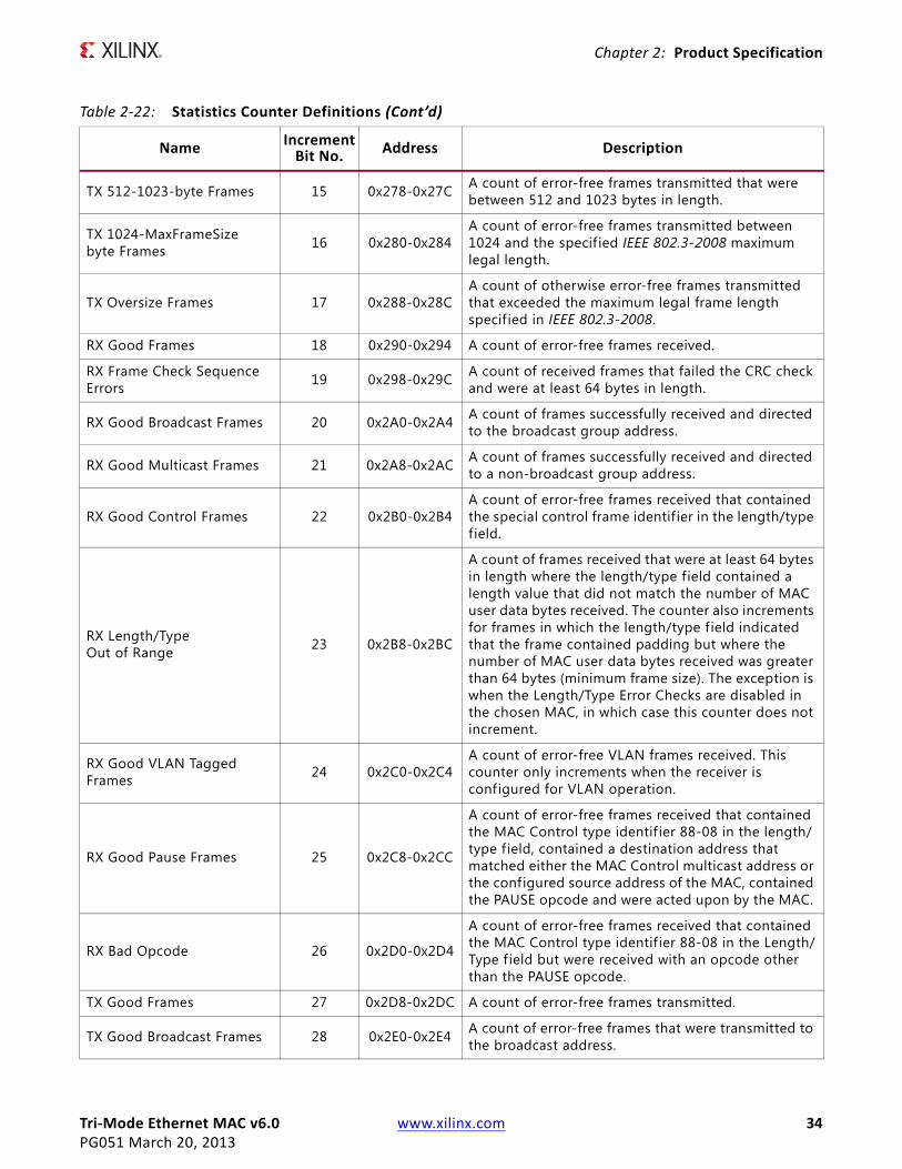
Statistics CountersThe Statistics counters can be defined to be either 32 or 64 bits wide, with 64 bits being the default. When defined as 64-bits wide the counter values are captured across two registers. In all cases a read of the lower 32-bit value causes the upper 32 bits to be sampled. A subsequent read of the upper 32-bit location returns this sampled value.
Note: If a different upper 32-bit location is read, an error is returned.
Table 2-22: Statistics Counter Definitions
Name IncrementBit No. Address Description
Received bytes NA 0x200-0x204 A count of bytes of frames received (destination address to frame check sequence inclusive).
Transmitted bytes NA 0x208-0x20C A count of bytes of frames transmitted (destination address to frame check sequence inclusive).
RX Undersize frames NA 0x210-0x214A count of the number of frames received that were fewer than 64 bytes in length but otherwise well formed.
RX Fragment frames NA 0x218-0x21CA count of the number of frames received that were fewer than 64 bytes in length and had a bad frame check sequence f ield.
RX 64-byte Frames 4 0x220-0x224 A count of error-free frames received 64 bytes in length.
RX 65-127-byte Frames 5 0x228-0x22C A count of error-free frames received between 65 and 127 bytes in length.
RX 128-255-byte Frames 6 0x230-0x234 A count of error-free frames received between 128 and 255 bytes in length.
RX 256-511-byte Frames 7 0x238-0x23C A count of error-free frames received between 256 and 511 bytes in length.
RX 512-1023-byte Frames 8 0x240-0x244 A count of error-free frames received between 512 and 1023 bytes in length.
RX 1024-MaxFrameSizebyte Frames 9 0x248-0x24C
A count of error-free frames received between 1024 bytes and the specif ied IEEE 802.3-2008 maximum legal length.
RX Oversize Frames 10 0x250-0x254A count of otherwise error-free frames received that exceeded the maximum legal frame length specified in IEEE 802.3-2008.
TX 64-byte Frames 11 0x258-0x25C A count of error-free frames transmitted that were 64 bytes in length.
TX 65-127-byte Frames 12 0x260-0x264 A count of error-free frames transmitted between 65 and 127 bytes in length.
TX 128-255-byte Frames 13 0x268-0x26C A count of error-free frames transmitted between 128 and 255 bytes in length.
TX 256-511-byte Frames 14 0x270-0x274 A count of error-free frames transmitted between 256 and 511 bytes in length.
Tri-Mode Ethernet MAC v6.0 www.xilinx.com 34PG051 March 20, 2013
Chapter 2: Product Specification
TX 512-1023-byte Frames 15 0x278-0x27C A count of error-free frames transmitted that were between 512 and 1023 bytes in length.
TX 1024-MaxFrameSizebyte Frames 16 0x280-0x284
A count of error-free frames transmitted between 1024 and the specif ied IEEE 802.3-2008 maximum legal length.
TX Oversize Frames 17 0x288-0x28CA count of otherwise error-free frames transmitted that exceeded the maximum legal frame length specif ied in IEEE 802.3-2008.
RX Good Frames 18 0x290-0x294 A count of error-free frames received.
RX Frame Check SequenceErrors 19 0x298-0x29C A count of received frames that failed the CRC check
and were at least 64 bytes in length.
RX Good Broadcast Frames 20 0x2A0-0x2A4 A count of frames successfully received and directed to the broadcast group address.
RX Good Multicast Frames 21 0x2A8-0x2AC A count of frames successfully received and directed to a non-broadcast group address.
RX Good Control Frames 22 0x2B0-0x2B4A count of error-free frames received that contained the special control frame identif ier in the length/type field.
RX Length/TypeOut of Range 23 0x2B8-0x2BC
A count of frames received that were at least 64 bytes in length where the length/type field contained a length value that did not match the number of MAC user data bytes received. The counter also increments for frames in which the length/type f ield indicated that the frame contained padding but where the number of MAC user data bytes received was greater than 64 bytes (minimum frame size). The exception is when the Length/Type Error Checks are disabled in the chosen MAC, in which case this counter does not increment.
RX Good VLAN TaggedFrames 24 0x2C0-0x2C4
A count of error-free VLAN frames received. This counter only increments when the receiver is configured for VLAN operation.
RX Good Pause Frames 25 0x2C8-0x2CC
A count of error-free frames received that contained the MAC Control type identif ier 88-08 in the length/type field, contained a destination address that matched either the MAC Control multicast address or the configured source address of the MAC, contained the PAUSE opcode and were acted upon by the MAC.
RX Bad Opcode 26 0x2D0-0x2D4
A count of error-free frames received that contained the MAC Control type identif ier 88-08 in the Length/Type f ield but were received with an opcode other than the PAUSE opcode.
TX Good Frames 27 0x2D8-0x2DC A count of error-free frames transmitted.
TX Good Broadcast Frames 28 0x2E0-0x2E4 A count of error-free frames that were transmitted to the broadcast address.
Table 2-22: Statistics Counter Definitions (Cont’d)
Name IncrementBit No. Address Description

Tri-Mode Ethernet MAC v6.0 www.xilinx.com 35PG051 March 20, 2013
Chapter 2: Product Specification
TX Good Multicast Frames 29 0x2E8-0x2EC A count of error-free frames that were transmitted to a group destination address other than broadcast.
TX Good Underrun Errors 30 0x2F0-0x2F4
A count of frames that would otherwise be transmitted by the core but could not be completed due to the assertion of TX_UNDERRUN during the frame transmission.
TX Good Control Frames 31 0x2F8-0x2FCA count of error-free frames transmitted that contained the MAC Control Frame type identif ier 88-08 in the length/type f ield.
TX Good VLAN Tagged Frames 32 0x300-0x304
A count of error-free VLAN frames transmitted. This counter only increments when the transmitter is configured for VLAN operation.
TX Good Pause Frames 33 0x308-0x30CA count of error-free PAUSE frames generated and transmitted by the MAC in response to an assertion of pause_req.
TX Single Collision Frames 34 0x310-0x314A count of frames involved in a single collision but subsequently transmitted successfully (half-duplex mode only).
TX Multiple Collision Frames 35 0x318-0x31CA count of frames involved in more than one collision but subsequently transmitted successfully (half-duplex mode only).
TX Deferred 36 0x320-0x324A count of frames whose transmission was delayed on its f irst attempt because the medium was busy (half-duplex mode only).
TX Late Collisions 37 0x328-0x32C
A count of the times that a collision has been detected later than one slot Time from the start of the packet transmission. A late collision is counted twice— both as a collision and as a late Collision (half-duplex mode only).
TX Excess Collisions 38 0x330-0x334A count of the frames that, due to excessive collisions, are not transmitted successfully (half-duplex mode only).
TX Excess Deferral 39 0x338-0x33C A count of frames that deferred transmission for an excessive period of time (half-duplex mode only).
TX Alignment Errors 40 0x340-0x344Asserted for received frames of size 64-bytes and greater which contained an odd number of received nibbles and which also contained an invalid FCS f ield.
1. All bits are Read Only.
Table 2-22: Statistics Counter Definitions (Cont’d)
Name IncrementBit No. Address Description

Tri-Mode Ethernet MAC v6.0 www.xilinx.com 36PG051 March 20, 2013
Chapter 2: Product Specification
MAC Configuration RegistersConfiguration of the MAC core is performed through a register bank accessed through the management interface. The configuration registers available in the core are detailed in Table 2-23.
The contents of each configuration register are shown in Tables 2-24 to 2-32.
Table 2-23: Configuration Registers
Address (Hex) Description
0x400 Receiver Configuration Word 0 (0x400)
0x404 Receiver Configuration Word 1 (0x404)
0x408 Transmitter Configuration Word (0x408)
0x40C Flow Control Configuration Word (0x40C)
0x410 MAC Speed Configuration Word (0x410)
0x414 RX Max Frame Configuration Word (0x414)
0x418 TX Max Frame Configuration Word (0x418)
0x41C-0x4F4 Reserved
0x4F8 ID Register (0x4F8)
0x4FC Ability Register (0x4FC)
Table 2-24: Receiver Configuration Word 0 (0x400)
Bits DefaultValue Type Description
31:0 All 0s Read/Write (R/W)
Pause frame MAC Source Address[31:0]: This address is used by the MAC to match against the destination address of any incoming flow control frames. It is also used by the flow control block as the source address (SA) for any outbound flow control frames.The address is ordered so the first byte transmitted/received is the lowest positioned byte in the register; for example, a MAC address of AA-BB-CC-DD-EE-FF would be stored in Address[47:0] as 0xFFEEDDCCBBAA.
Table 2-25: Receiver Configuration Word 1 (0x404)
Bits DefaultValue Type Description
31 0 R/W Reset: When this bit is set to 1, the receiver is reset. The bit then automatically reverts to 0. This reset also sets all of the receiver configuration registers to their default values.
30 0 R/W Jumbo Frame Enable: When this bit is set to 1, the MAC receiver accepts frames over the specif ied IEEE 802.3-2008 maximum legal length. When this bit is 0, the MAC only accepts frames up to the specif ied maximum.
29 0 R/W In-band FCS Enable: When this bit is 1, the MAC receiver passes the FCS f ield up to the client as described in User-Supplied FCS Passing. When it is 0, the client is not passed to the FCS. In both cases, the FCS is verif ied on the frame.
Tri-Mode Ethernet MAC v6.0 www.xilinx.com 37PG051 March 20, 2013
Chapter 2: Product Specification
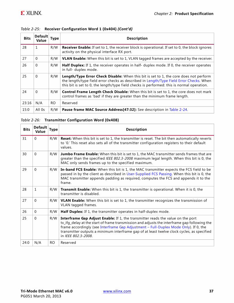
28 1 R/W Receiver Enable: If set to 1, the receiver block is operational. If set to 0, the block ignores activity on the physical interface RX port.
27 0 R/W VLAN Enable: When this bit is set to 1, VLAN tagged frames are accepted by the receiver.
26 0 R/W Half Duplex: If 1, the receiver operates in half- duplex mode. If 0, the receiver operates in full- duplex mode.
25 0 R/W Length/Type Error Check Disable: When this bit is set to 1, the core does not perform the length/type field error checks as described in Length/Type Field Error Checks. When this bit is set to 0, the length/type f ield checks is performed: this is normal operation.
24 0 R/W Control Frame Length Check Disable: When this bit is set to 1, the core does not mark control frames as ‘bad’ if they are greater than the minimum frame length.
23:16 N/A RO Reserved
15:0 All 0s R/W Pause frame MAC Source Address[47:32]: See description in Table 2-24.
Table 2-25: Receiver Configuration Word 1 (0x404) (Cont’d)
Bits DefaultValue Type Description
Table 2-26: Transmitter Configuration Word (0x408)
Bits DefaultValue Type Description
31 0 R/W Reset: When this bit is set to 1, the transmitter is reset. The bit then automatically reverts to ‘0.’ This reset also sets all of the transmitter configuration registers to their default values.
30 0 R/W Jumbo Frame Enable: When this bit is set to 1, the MAC transmitter sends frames that are greater than the specif ied IEEE 802.3-2008 maximum legal length. When this bit is 0, the MAC only sends frames up to the specif ied maximum.
29 0 R/W In-band FCS Enable: When this bit is 1, the MAC transmitter expects the FCS f ield to be passed in by the client as described in User-Supplied FCS Passing. When this bit is 0, the MAC transmitter appends padding as required, computes the FCS and appends it to the frame.
28 1 R/W Transmit Enable: When this bit is 1, the transmitter is operational. When it is 0, the transmitter is disabled.
27 0 R/W VLAN Enable: When this bit is set to 1, the transmitter recognizes the transmission of VLAN tagged frames.
26 0 R/W Half Duplex: If 1, the transmitter operates in half-duplex mode.
25 0 R/W Interframe Gap Adjust Enable: If 1, the transmitter reads the value on the port tx_ifg_delay at the start of frame transmission and adjusts the interframe gap following the frame accordingly (see Interframe Gap Adjustment – Full-Duplex Mode Only). If 0, the transmitter outputs a minimum interframe gap of at least twelve clock cycles, as specified in IEEE 802.3-2008.
24:0 N/A RO Reserved

Tri-Mode Ethernet MAC v6.0 www.xilinx.com 38PG051 March 20, 2013
Chapter 2: Product Specification
Table 2-27: Flow Control Configuration Word (0x40C)
Bits DefaultValue Type Description
31 N/A RO Reserved
30 1 R/W Flow Control Enable (TX): When this bit is 1, asserting the pause_req signal sends a flow control frame out from the transmitter as described in Transmitting a Pause Control Frame. When this bit is 0, asserting the pause_req signal has no effect.
29 1 R/W Flow Control Enable (RX): When this bit is 1, received flow control frames inhibits the transmitter operation as described in Receiving a Pause Control Frame. When this bit is 0, received flow control frames are always passed up to the client.
28:0 N/A RO Reserved
Table 2-28: MAC Speed Configuration Word (0x410)
Bits DefaultValue Type Description
31:30 10 R/W MAC Speed Configuration00 = 10 Mb/s01 = 100 Mb/s10 = 1 Gb/sWhen the TEMAC solution has been generated for only 1 Gb/s speed support, Bits[31:30] are hard-coded to the value 10.When the TEMAC solution has been generated for only 10 Mb/s and 100 Mb/s speed support, Bits[31:30] only accept the values of 00 to configure for 10 Mb/s operation, or 01 to configure for 100 Mb/s operation.
29:0 N/A RO Reserved1. The setting of the MAC Speed Configuration register is not affected by a reset.
Table 2-29: RX Max Frame Configuration Word (0x414)
Bits DefaultValue Type Description
31:17 N/A RO Reserved
16 0 R/W RX Max Frame Enable: When low, the MAC assumes use of the standard 1518/1522 depending upon the setting of VLAN enable. When high, the MAC allows frames up to RX Max Frame Length irrespective of the value of VLAN enable. If Jumbo Enable is set then this register has no effect. See Maximum Permitted Frame Length.
15 N/A RO Reserved
14:0 0x5EE R/W RX Max Frame Length
Tri-Mode Ethernet MAC v6.0 www.xilinx.com 39PG051 March 20, 2013
Chapter 2: Product Specification
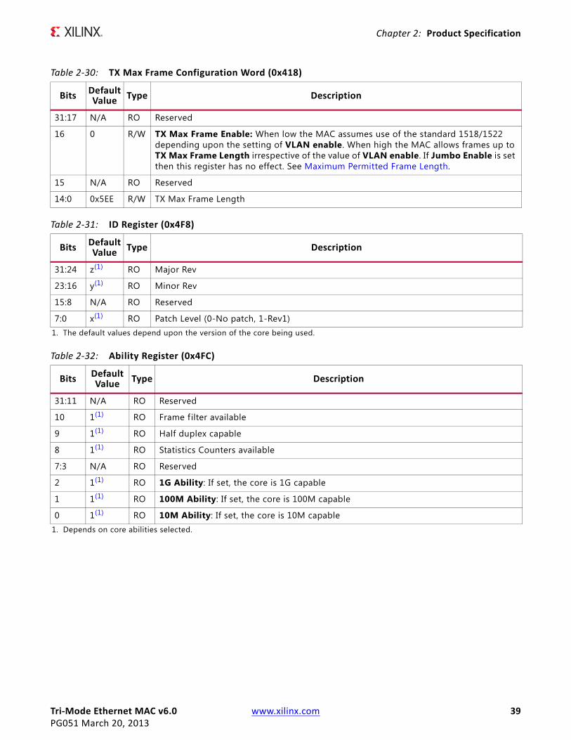
Table 2-30: TX Max Frame Configuration Word (0x418)
Bits DefaultValue Type Description
31:17 N/A RO Reserved
16 0 R/W TX Max Frame Enable: When low the MAC assumes use of the standard 1518/1522 depending upon the setting of VLAN enable. When high the MAC allows frames up to TX Max Frame Length irrespective of the value of VLAN enable. If Jumbo Enable is set then this register has no effect. See Maximum Permitted Frame Length.
15 N/A RO Reserved
14:0 0x5EE R/W TX Max Frame Length
Table 2-31: ID Register (0x4F8)
Bits DefaultValue Type Description
31:24 z(1) RO Major Rev
23:16 y(1) RO Minor Rev
15:8 N/A RO Reserved
7:0 x(1) RO Patch Level (0-No patch, 1-Rev1)1. The default values depend upon the version of the core being used.
Table 2-32: Ability Register (0x4FC)
Bits Default Value Type Description
31:11 N/A RO Reserved
10 1(1) RO Frame filter available
9 1(1) RO Half duplex capable
8 1(1) RO Statistics Counters available
7:3 N/A RO Reserved
2 1(1) RO 1G Ability: If set, the core is 1G capable
1 1(1) RO 100M Ability: If set, the core is 100M capable
0 1(1) RO 10M Ability: If set, the core is 10M capable1. Depends on core abilities selected.

Tri-Mode Ethernet MAC v6.0 www.xilinx.com 40PG051 March 20, 2013
Chapter 2: Product Specification
MDIOAccess to the MDIO interface through the management interface is entirely register mapped. A list of the MDIO registers is shown in Table 2-33. See MDIO Interface for more detail.
The contents of each configuration register are shown in Tables 2-34 to 2-37.
Table 2-33: MDIO Configuration Registers
Address (Hex) Description
0x500 MDIO Setup Word (0x500)
0x504 MDIO Control Word (0x504)
0x508 MDIO Write Data (0x508)
0x50C MDIO Read Data (0x50C)
Table 2-34: MDIO Setup Word (0x500)
Bits DefaultValue Type Description
31:7 N/A RO Reserved
6 0x0 R/W MDIO Enable: When this bit is 1, the MDIO interface can be used to access attached PHY devices. When this bit is 0, the MDIO interface is disabled and the MDIO signals remain inactive. A write to this bit only takes effect if Clock Divide is set to a nonzero value.
5:0 0x0 R/W Clock Divide[5:0]: See Accessing PHY Configuration Registers, through MDIO Using the Management Interface, page 118
Table 2-35: MDIO Control Word (0x504)
Bits DefaultValue Type Description
31:29 N/A RO Reserved
28:24 0x0 R/W TX_PHYAD: This controls the PHY address being accessed.
23:21 N/A RO Reserved
20:16 0x0 R/W TX_REGAD: This controls the register address being accessed.
15:14 0x0 R/W TX_OP: This f ield controls the type of access performed when a one is written to initiate.
13:12 N/A RO Reserved
10:8 N/A RO Reserved
11 0x0 WO Initiate: Writing a 1 to this bit starts an MDIO transfer.
7 0x0 RO MDIO ready: When set the MDIO is enabled and ready for a new transfer. This is also used to identify when a previous transaction has completed (for example, Read data is valid).
6:0 N/A RO Reserved

Tri-Mode Ethernet MAC v6.0 www.xilinx.com 41PG051 March 20, 2013
Chapter 2: Product Specification
Interrupt Controller
Bit[0] of all interrupt registers is used to indicate the MDIO Transaction complete interrupt. Bits[31:1] are Reserved. AVB Interrupts are handled through the dedicated AVB interrupt registers.
Frame Filter ConfigurationTables 2-40 to 2-45 describe the registers used to access the optional frame filter configuration when the TEMAC solution is implemented with a frame filter. In addition to the unicast address, broadcast address and pause addresses, the frame filter can optionally be generated to respond to up to eight additional configurable frame filter matches. These are stored in an address table within the frame filter. See Frame Filter in Chapter 3.
If no frame filter is present, these registers do not exist and return 0s for a read from the stated addresses.
Table 2-39 shows the frame filter configuration registers.
Table 2-36: MDIO Write Data (0x508)
Bits Default Value Type Description
31:16 N/A RO Reserved
15:0 0x0000 R/W Write Data
Table 2-37: MDIO Read Data (0x50C)
Bits Default Value Type Description
31:17 N/A RO Reserved
16 0x0 RO MDIO Ready: This is a copy of Bit[7] of the MDIO Control Word.
15:0 0x0000 RO Read Data: Only valid when MDIO ready is sampled high.
Table 2-38: Interrupt Controller Configuration
Address(Hex)
Default Value Type Description
0x600 0x00 RO Interrupt Status Register. Indicates the status of an interrupt.
0x610 0x00 RO Interrupt Pending Register. Indicates the pending status of an interrupt. Bits in this register are only set when the corresponding bits in IER and ISR are set.
0x620 0x00 R/W Interrupt Enable Register. Indicates the enable state of an interrupt. Writing a 1 to any bit enables that particular interrupt.
0x630 0x00 WO Interrupt Clear Register. Writing a 1 to any bit of this register clears that particular interrupt.

Tri-Mode Ethernet MAC v6.0 www.xilinx.com 42PG051 March 20, 2013
Chapter 2: Product Specification
Table 2-39: Frame Filter Configuration
Address (Hex) Description
0x700 Unicast Address (Word 0) (0x700)
0x704 Unicast Address (Word 1) (0x704)
0x708 Frame Filter Control (0x708)
0x70C Frame Filter Enable (0x70C)
0x710 Frame Filter value bytes 3-0
0x714 Frame filter value bytes 7-4
0x718 Frame filter value bytes 11-8
0x71C Frame filter value bytes 15-12
0x720 Frame filter value bytes 19-16
0x724 Frame filter value bytes 23-20
0x728 Frame filter value bytes 27-24
0x72C Frame filter value bytes 31-28
0x730 Frame filter value bytes 35-32
0x734 Frame filter value bytes 39-36
0x738 Frame filter value bytes 43-40
0x73C Frame filter value bytes 47-44
0x740 Frame filter value bytes 51-48
0x744 Frame filter value bytes 55-52
0x748 Frame filter value bytes 59-56
0x74C Frame filter value bytes 63-60
0x750 Frame f ilter mask value bytes 3-0
0x754 Frame f ilter mask value bytes 7-4
0x758 Frame f ilter mask value bytes 11-8
0x75C Frame f ilter mask value bytes 15-12
0x760 Frame f ilter mask value bytes 19-16
0x764 Frame f ilter mask value bytes 23-20
0x768 Frame f ilter mask value bytes 27-24
0x76C Frame f ilter mask value bytes 31-28
0x770 Frame f ilter mask value bytes 35-32
0x774 Frame f ilter mask value bytes 39-36
0x778 Frame f ilter mask value bytes 43-40
0x77C Frame f ilter mask value bytes 47-44
0x780 Frame f ilter mask value bytes 51-48
0x784 Frame f ilter mask value bytes 55-52
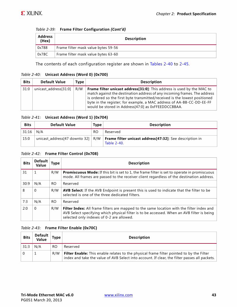
Tri-Mode Ethernet MAC v6.0 www.xilinx.com 43PG051 March 20, 2013
Chapter 2: Product Specification
The contents of each configuration register are shown in Tables 2-40 to 2-45.
0x788 Frame f ilter mask value bytes 59-56
0x78C Frame f ilter mask value bytes 63-60
Table 2-39: Frame Filter Configuration (Cont’d)
Address (Hex) Description
Table 2-40: Unicast Address (Word 0) (0x700)
Bits Default Value Type Description
31:0 unicast_address[31:0] R/W Frame filter unicast address[31:0]: This address is used by the MAC to match against the destination address of any incoming frames. The address is ordered so the first byte transmitted/received is the lowest positioned byte in the register; for example, a MAC address of AA-BB-CC-DD-EE-FF would be stored in Address[47:0] as 0xFFEEDDCCBBAA.
Table 2-41: Unicast Address (Word 1) (0x704)
Bits Default Value Type Description
31:16 N/A RO Reserved
15:0 unicast_address[47 downto 32] R/W Frame filter unicast address[47:32]: See description in Table 2-40.
Table 2-42: Frame Filter Control (0x708)
Bits Default Value Type Description
31 1 R/W Promiscuous Mode: If this bit is set to 1, the frame f ilter is set to operate in promiscuous mode. All frames are passed to the receiver client regardless of the destination address.
30:9 N/A RO Reserved
8 0 R/W AVB Select: If the AVB Endpoint is present this is used to indicate that the f ilter to be selected is one of the three dedicated f ilters.
7:3 N/A RO Reserved
2:0 0 R/W Filter Index: All frame filters are mapped to the same location with the f ilter index and AVB Select specifying which physical f ilter is to be accessed. When an AVB f ilter is being selected only indexes of 0-2 are allowed.
Table 2-43: Frame Filter Enable (0x70C)
Bits Default Value Type Description
31:3 N/A RO Reserved
0 1 R/W Filter Enable: This enable relates to the physical frame filter pointed to by the Filter index and take the value of AVB Select into account. If clear, the filter passes all packets.

Tri-Mode Ethernet MAC v6.0 www.xilinx.com 44PG051 March 20, 2013
Chapter 2: Product Specification
AVB Specific Frame Filters
This section is only applicable if the TEMAC solution is implemented with the optional Ethernet AVB Endpoint option.
PTP Frame Filter
The PTP frame filter is at AVB index 0 and is initialized to match the following:
Destination Address = 0x0E0000C28001Type = 0xF788
This translates to the following register settings:
Table 2-44: Frame Filter Value (0x710-0x74C)
Bits Default Value Type Description
31:0 Bits[47:0] = 1All other = 0
R/W Filter Value All f ilter value registers have the same format. The lower 31 bits of f ilter value, at address 0x710, relating to the f ilter at physical Frame Filter index, that is to be written to the address table. The value is ordered so that the first byte transmitted/received is the lowest positioned byte in the register; for example, a MAC address of AA-BB-CC-DD-EE-FF would be stored in Filter Value[47:0] as 0xFFEEDDCCBBAA.By default the frame filters are configured to match against the broadcast address.
Table 2-45: Frame Filter Mask Value (0x750-0x790)
Bits Default Value Type Description
31:0 Bits[47:0] = 1All other = 0
R/W Mask Value.All mask value registers have the same format.If a mask bit is set to 1 then the corresponding bit of the Filter Value is compared by the frame filter. For example, if a basic Destination address comparison was desired then Bits[47:0] should be written to 1 and all other bits to 0.
Table 2-46: PTP Frame Filter Value (0x710-0x74C)
Address Default Value Description
0x710 0x00C28001 First four bytes of the AVB Special address
0x714 0x00000E00 Final two bytes of the AVB Special Address and f irst two bytes of the source address
0x718 0x0 Final four bytes of the source address
0x71C 0x0000f788 Type f ield
0x720-0x74C 0x0 Not Used

Tri-Mode Ethernet MAC v6.0 www.xilinx.com 45PG051 March 20, 2013
Chapter 2: Product Specification
SR Classes A and B Frame Filters
AVB EndpointThis section describes the registers used for setting up and operating the optional AVB Endpoint functionality.
Table 2-47: PTP Frame Filter Mask Value (0x750-0x790)
Address Default Value Description
0x750 0xFFFFFFFF Match against the Destination address
0x754 0x0000FFFF Match against the destination address but not the source address.
0x758 0x0 Do not match against source address.
0x75C 0x0000FFFF Match against the Type f ield
0x760-0x790 0x0 Not Used
Table 2-48: SR Class A (Index 1) Frame Filter Value (0x710-0x74C)
Address Default Value Description
0x710-0x718 0x0 Not Used
0x71C 0x02600081 Match against VLAN field with PCP field set to 3 and ID f ield set to 2
0x720-0x74C 0x0 Not Used
Table 2-49: SR Class A (Index 1) Frame Filter Mask Value (0x750-0x790)
Address Default Value Description
0x750-758 0x0 Not Used
0x75C 0xFFFFFFFF Match against Type f ield and type info field
0x760-0x790 0x0 Not Used
Table 2-50: SR Class B (Index 2) Frame Filter Value (0x710-0x74C)
Address Default Value Description
0x710-0x718 0x0 Not Used
0x71C 0x02400081 Match against VLAN field with PCP f ield set to 2 and ID field set to 2
0x720-0x74C 0x0 Not Used
Table 2-51: SR CLass B (Index 2) Frame Filter Mask Value (0x750-0x790)
Address Default Value Description
0x750-758 0x0 Not Used
0x75C 0xFFFFFFFF Match against Type field and type info field
0x760-0x790 0x0 Not Used

Tri-Mode Ethernet MAC v6.0 www.xilinx.com 46PG051 March 20, 2013
Chapter 2: Product Specification
RX PTP Packet Buffer Address Space
The RX PTP Packet buffers are only available when the AVB functionality is included in the TEMAC core. The Address space of the RX PTP Packet Buffer is 4K in total. This represents the size of a single FPGA block RAM pair (4K). Every byte of this block RAM can be read.
The Address space of the RX PTP Packet Buffers is 4K in total. This represents the size of a single FPGA block RAM pair (4K). Every byte of this block RAM can be read.
This address space is divided equally into 16 separate buffers of 256 bytes, each of which is capable of storing a unique PTP frame. When received, a PTP frame is written into one of these buffers; then the buffer write pointer increments and points to the next buffer in preparation for subsequent PTP frame reception.
Within each buffer, the entire PTP frame is written in (from MAC Destination Address through to the last byte from the data f ield), starting at the base address of that buffer. Following PTP frame reception, the RX timestamp captured for that frame is written into the top 4 bytes of the buffer used. A list of the RX PTP Buffers is shown in Table 2-52.
Table 2-52: RX PTP Buffers
Address (Hex) Description
0x10000-0x100FC RX PTP Buffer 0
0x10100-0x101FC RX PTP Buffer 1
0x10200-0x102FC RX PTP Buffer 2
0x10300-0x103FC RX PTP Buffer 3
0x10400-0x104FC RX PTP Buffer 4
0x10500-0x105FC RX PTP Buffer 5
0x10600-0x106FC RX PTP Buffer 6
0x10700-0x107FC RX PTP Buffer 7
0x10800-0x108FC RX PTP Buffer 8
0x10900-0x109FC RX PTP Buffer 9
0x10A00-0x10AFC RX PTP Buffer 10
0x10B00-0x10BFC RX PTP Buffer 11
0x10C00-0x10CFC RX PTP Buffer 12
0x10D00-0x10DFC RX PTP Buffer 13
0x10E00-0x10EFC RX PTP Buffer 14
0x10F00-0x10FFC RX PTP Buffer 15

Tri-Mode Ethernet MAC v6.0 www.xilinx.com 47PG051 March 20, 2013
Chapter 2: Product Specification
TX PTP Packet Buffer Address Space
The TX PTP Packet buffers are only available when the AVB functionality is included in the TEMAC core.
The Address space of the TX PTP Packet Buffer is 2K in total, representing the size of a single FPGA block 18K RAM. Every byte of this block RAM is accessible by the CPU. This address space is divided equally into eight separate buffers of 256 bytes, each of which is capable of storing a unique PTP frame: seven of these buffer locations are pre-initialized with standard PTP frame syntax; however, each byte can be modified if desired.
Within each single buffer, the initial byte is used as a length f ield, used to indicate to the core logic the number of bytes to be transmitted for that frame. An entire PTP frame (from MAC Destination Address through to the last byte from the data field) is then stored, starting at the eighth address of that particular buffer. Following PTP frame transmission from one of these buffers, the TX Timestamp captured for that frame is written into the top four bytes of the buffer just used. See TX PTP Packet Buffer for more details. A list of the TX PTP Buffers is shown in Table 2-53.
AVB Configuration
The AVB configuration registers are only present when the AVB is included in the TEMAC core. These registers are used by the software drivers to control the AVB functionality.
A list of the AVB Configuration registers is shown in Table 2-54.
Table 2-53: TX PTP Buffers
Address (Hex) Description
0x11000-0x110FC TX PTP Buffer 0 – Initialized for a SYNC frame.
0x11100-0x111FC TX PTP Buffer 1 – Initialized for a Follow up frame.
0x11200-0x112FC TX PTP Buffer 2 – Initialized for a Pdelay request frame.
0x11300-0x113FC TX PTP Buffer 3 – Initialized for a Pdelay response frame.
0x11400-0x114FC TX PTP Buffer 4 – Initialized for a Pdelay response follow up frame.
0x11500-0x115FC TX PTP Buffer 5 – Initialized for an Announce frame.
0x11600-0x116FC TX PTP Buffer 6 – Initialized for a Signaling frame.
0x11700-0x117FC TX PTP Buffer 7
Table 2-54: AVB Configuration Registers
Address (Hex) Description
0x12000 TX PTP Packet Buffer Control Register
0x12004 RX PTP Packet Buffer Control Register
0x12008 Reserved
0x1200C TX Arbiter Send Slope Control Register
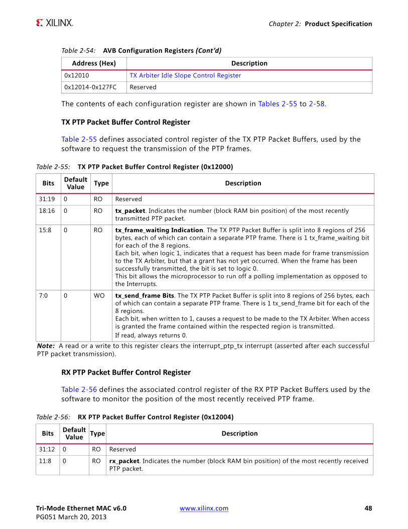
Tri-Mode Ethernet MAC v6.0 www.xilinx.com 48PG051 March 20, 2013
Chapter 2: Product Specification
The contents of each configuration register are shown in Tables 2-55 to 2-58.
TX PTP Packet Buffer Control Register
Table 2-55 defines associated control register of the TX PTP Packet Buffers, used by the software to request the transmission of the PTP frames.
RX PTP Packet Buffer Control Register
Table 2-56 defines the associated control register of the RX PTP Packet Buffers used by the software to monitor the position of the most recently received PTP frame.
0x12010 TX Arbiter Idle Slope Control Register
0x12014-0x127FC Reserved
Table 2-54: AVB Configuration Registers (Cont’d)
Address (Hex) Description
Table 2-55: TX PTP Packet Buffer Control Register (0x12000)
Bits DefaultValue Type Description
31:19 0 RO Reserved
18:16 0 RO tx_packet. Indicates the number (block RAM bin position) of the most recently transmitted PTP packet.
15:8 0 RO tx_frame_waiting Indication. The TX PTP Packet Buffer is split into 8 regions of 256 bytes, each of which can contain a separate PTP frame. There is 1 tx_frame_waiting bit for each of the 8 regions.Each bit, when logic 1, indicates that a request has been made for frame transmission to the TX Arbiter, but that a grant has not yet occurred. When the frame has been successfully transmitted, the bit is set to logic 0.This bit allows the microprocessor to run off a polling implementation as opposed to the Interrupts.
7:0 0 WO tx_send_frame Bits. The TX PTP Packet Buffer is split into 8 regions of 256 bytes, each of which can contain a separate PTP frame. There is 1 tx_send_frame bit for each of the 8 regions.Each bit, when written to 1, causes a request to be made to the TX Arbiter. When access is granted the frame contained within the respected region is transmitted.If read, always returns 0.
Note: A read or a write to this register clears the interrupt_ptp_tx interrupt (asserted after each successful PTP packet transmission).
Table 2-56: RX PTP Packet Buffer Control Register (0x12004)
Bits Default Value Type Description
31:12 0 RO Reserved
11:8 0 RO rx_packet. Indicates the number (block RAM bin position) of the most recently received PTP packet.

Tri-Mode Ethernet MAC v6.0 www.xilinx.com 49PG051 March 20, 2013
Chapter 2: Product Specification
TX Arbiter Send Slope Control Register
The SendSlope variable is defined in IEEE802.1Qav-2009 to be the rate of change of credit, in bits per second, when the value of credit is decreasing (during AV packet transmission). Together with TX Arbiter Idle Slope Control Register, RTC Nanoseconds Field Offset Control and RTC Seconds Field Offset Control, these registers define the maximum limit of the bandwidth reserved for AV traff ic, as enforced by the TX Arbiter. The default values allow the maximum bandwidth proportion of 75% for the AV traff ic. See the IEEE 802.3-2008 specification [Ref 8] for further information.
TX Arbiter Idle Slope Control Register
The idleSlope variable is defined in IEEE802.1Qav-2009 to be the rate of change of credit, in bits per second, when the value of credit is increasing (whenever there is no AV packet transmission). Together with TX Arbiter Send Slope Control Register, RTC Nanoseconds Field Offset Control, and RTC Seconds Field Offset Control, these registers define the maximum limit of the bandwidth reserved for AV traffic: this is enforced by the TX Arbiter. The default values allow the maximum bandwidth proportion of 75% for the AV traff ic. See the IEEE 802.3-2008 specification [Ref 8] for further information.
7:1 0 RO Reserved
0 0 WO rx_clear. When written with a 1, forces the buffer to empty, in practice moving the write address to the same value as the read address. If read, always returns 0.
Note: A read or a write to this register clears the interrupt_ptp_rx interrupt (asserted after each successful PTP packet reception).
Table 2-56: RX PTP Packet Buffer Control Register (0x12004) (Cont’d)
Bits Default Value Type Description
Table 2-57: TX Arbiter Send Slope Control Register (0x1200C)
Bits Default Value Type Description
31:20 0 RO Reserved
19:0 2048 R/W The value of sendSlope
Table 2-58: TX Arbiter Idle Slope Control Register (0x12010)
Bits Default Value Type Description
31:20 0 RO Reserved
19:0 6144 R/W The value of idleSlope
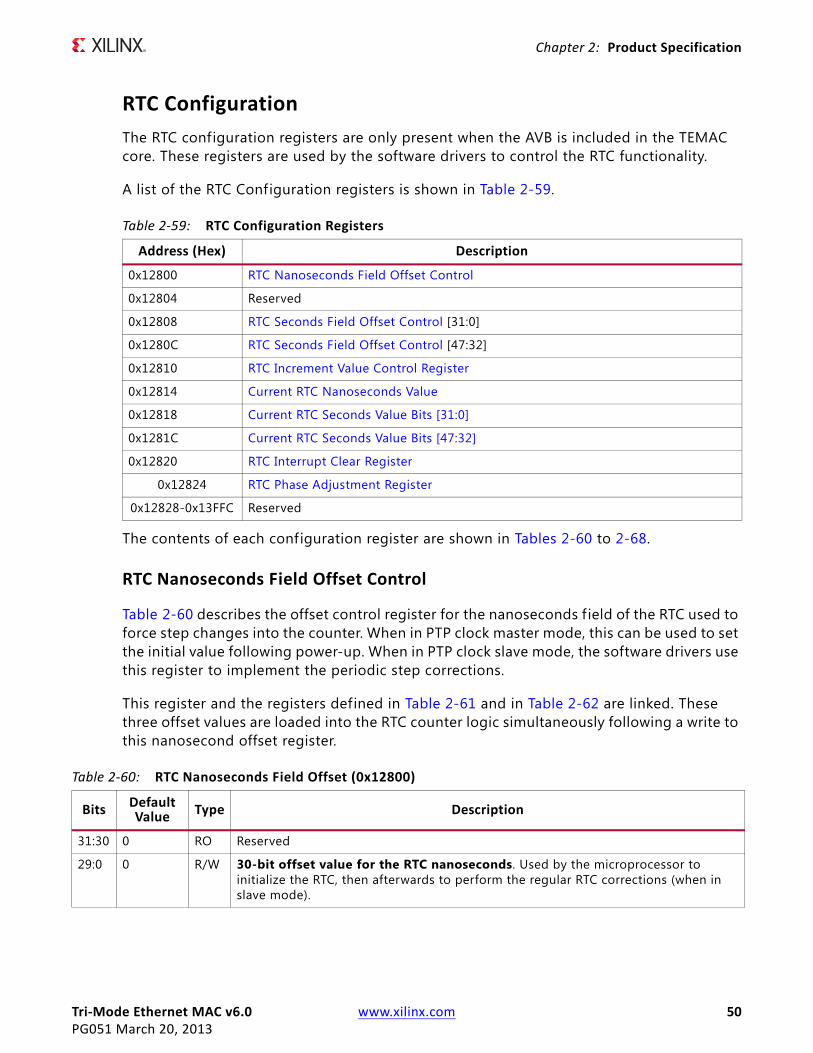
Tri-Mode Ethernet MAC v6.0 www.xilinx.com 50PG051 March 20, 2013
Chapter 2: Product Specification
RTC ConfigurationThe RTC configuration registers are only present when the AVB is included in the TEMAC core. These registers are used by the software drivers to control the RTC functionality.
A list of the RTC Configuration registers is shown in Table 2-59.
The contents of each configuration register are shown in Tables 2-60 to 2-68.
RTC Nanoseconds Field Offset Control
Table 2-60 describes the offset control register for the nanoseconds f ield of the RTC used to force step changes into the counter. When in PTP clock master mode, this can be used to set the initial value following power-up. When in PTP clock slave mode, the software drivers use this register to implement the periodic step corrections.
This register and the registers defined in Table 2-61 and in Table 2-62 are linked. These three offset values are loaded into the RTC counter logic simultaneously following a write to this nanosecond offset register.
Table 2-59: RTC Configuration Registers
Address (Hex) Description
0x12800 RTC Nanoseconds Field Offset Control
0x12804 Reserved
0x12808 RTC Seconds Field Offset Control [31:0]
0x1280C RTC Seconds Field Offset Control [47:32]
0x12810 RTC Increment Value Control Register
0x12814 Current RTC Nanoseconds Value
0x12818 Current RTC Seconds Value Bits [31:0]
0x1281C Current RTC Seconds Value Bits [47:32]
0x12820 RTC Interrupt Clear Register
0x12824 RTC Phase Adjustment Register
0x12828-0x13FFC Reserved
Table 2-60: RTC Nanoseconds Field Offset (0x12800)
Bits Default Value Type Description
31:30 0 RO Reserved
29:0 0 R/W 30-bit offset value for the RTC nanoseconds. Used by the microprocessor to initialize the RTC, then afterwards to perform the regular RTC corrections (when in slave mode).
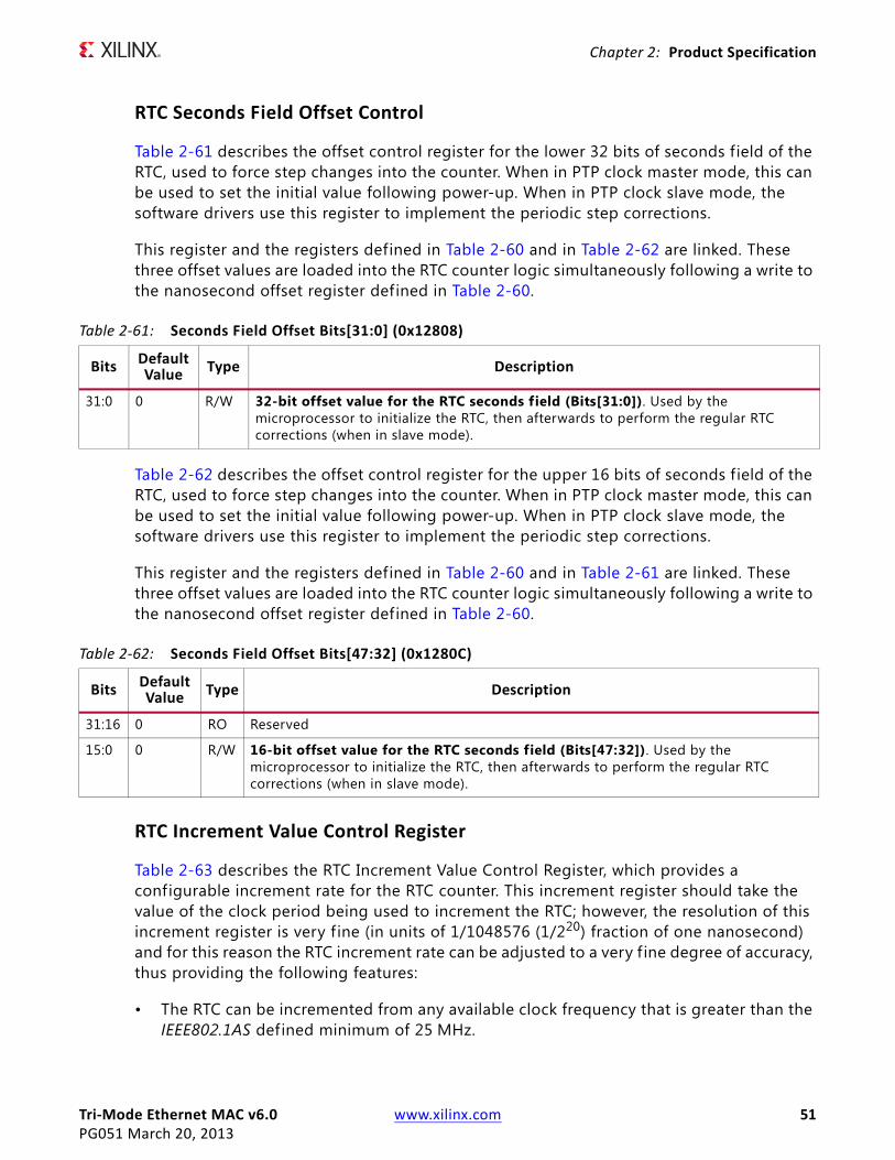
Tri-Mode Ethernet MAC v6.0 www.xilinx.com 51PG051 March 20, 2013
Chapter 2: Product Specification
RTC Seconds Field Offset Control
Table 2-61 describes the offset control register for the lower 32 bits of seconds field of the RTC, used to force step changes into the counter. When in PTP clock master mode, this can be used to set the initial value following power-up. When in PTP clock slave mode, the software drivers use this register to implement the periodic step corrections.
This register and the registers defined in Table 2-60 and in Table 2-62 are linked. These three offset values are loaded into the RTC counter logic simultaneously following a write to the nanosecond offset register defined in Table 2-60.
Table 2-62 describes the offset control register for the upper 16 bits of seconds field of the RTC, used to force step changes into the counter. When in PTP clock master mode, this can be used to set the initial value following power-up. When in PTP clock slave mode, the software drivers use this register to implement the periodic step corrections.
This register and the registers defined in Table 2-60 and in Table 2-61 are linked. These three offset values are loaded into the RTC counter logic simultaneously following a write to the nanosecond offset register defined in Table 2-60.
RTC Increment Value Control Register
Table 2-63 describes the RTC Increment Value Control Register, which provides a configurable increment rate for the RTC counter. This increment register should take the value of the clock period being used to increment the RTC; however, the resolution of this increment register is very f ine (in units of 1/1048576 (1/220) fraction of one nanosecond) and for this reason the RTC increment rate can be adjusted to a very f ine degree of accuracy, thus providing the following features:
• The RTC can be incremented from any available clock frequency that is greater than the IEEE802.1AS defined minimum of 25 MHz.
Table 2-61: Seconds Field Offset Bits[31:0] (0x12808)
Bits Default Value Type Description
31:0 0 R/W 32-bit offset value for the RTC seconds field (Bits[31:0]). Used by the microprocessor to initialize the RTC, then afterwards to perform the regular RTC corrections (when in slave mode).
Table 2-62: Seconds Field Offset Bits[47:32] (0x1280C)
Bits DefaultValue Type Description
31:16 0 RO Reserved
15:0 0 R/W 16-bit offset value for the RTC seconds field (Bits[47:32]). Used by the microprocessor to initialize the RTC, then afterwards to perform the regular RTC corrections (when in slave mode).

Tri-Mode Ethernet MAC v6.0 www.xilinx.com 52PG051 March 20, 2013
Chapter 2: Product Specification
• When acting as a clock slave, the rate adjustment of the RTC can be matched to that of the network clock master to an exceptional level of accuracy.
Current RTC Value Registers
Table 2-64 describes the nanoseconds field value register for the nanoseconds f ield of the RTV. When read, this returns the latest value of the counter. This register and the registers defined in Table 2-65 and in Table 2-66 are linked. When this nanoseconds value register is read, the entire RTC (including the seconds f ield) is sampled.
Table 2-65 describes the lower 32 bits of the seconds value register for the seconds f ield of the RTC. When read, this returns the latest value of the counter. This register and the registers defined in Table 2-64 and in Table 2-66 are linked. When the nanoseconds value register is read (see Table 2-64), the entire RTC is sampled.
Table 2-66 describes the upper 16 bits of the seconds value register for the seconds f ield of the RTC. When read, this returns the latest value of the counter. This register and the registers defined in Table 2-64 and in Table 2-65 are linked. When the nanoseconds value register is read (see Table 2-64), the entire RTC is sampled.
Table 2-63: RTC Increment Value Control Register (0x12810)
Bits Default Value Type Description
31:26 0 RO Reserved
25:0 0 R/W Per rtc_clk clock period Increment Value for the RTC.
Table 2-64: Current RTC Nanoseconds Value (0x12814)
Bits Default Value Type Description
31:30 0 RO Reserved
29:0 0 RO Current Value of the synchronized RTC nanoseconds f ield.
Note: A read from this register samples the entire RTC counter (synchronized) so that the Epoch and Seconds f ield are held static for a subsequent read.
Table 2-65: Current RTC Seconds Field Value Bits [31:0] (0x12818)
Bits Default Value Type Description
31:0 0 RO Sampled Value of the synchronized RTC Seconds f ield (Bits[31:0]).
Table 2-66: Current RTC Seconds Field Value Bits [47:32] (0x1281C)
Bits Default Value Type Description
31:16 0 RO Reserved
15:0 0 RO Sampled Value of the synchronized RTC Seconds f ield (Bits[47:32]).
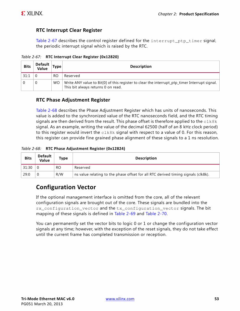
Tri-Mode Ethernet MAC v6.0 www.xilinx.com 53PG051 March 20, 2013
Chapter 2: Product Specification
RTC Interrupt Clear Register
Table 2-67 describes the control register defined for the interrupt_ptp_timer signal, the periodic interrupt signal which is raised by the RTC.
RTC Phase Adjustment Register
Table 2-68 describes the Phase Adjustment Register which has units of nanoseconds. This value is added to the synchronized value of the RTC nanoseconds f ield, and the RTC timing signals are then derived from the result. This phase offset is therefore applied to the clk8k signal. As an example, writing the value of the decimal 62500 (half of an 8 kHz clock period) to this register would invert the clk8k signal with respect to a value of 0. For this reason, this register can provide f ine grained phase alignment of these signals to a 1 ns resolution.
Configuration VectorIf the optional management interface is omitted from the core, all of the relevant configuration signals are brought out of the core. These signals are bundled into the rx_configuration_vector and the tx_configuration_vector signals. The bit mapping of these signals is defined in Table 2-69 and Table 2-70.
You can permanently set the vector bits to logic 0 or 1 or change the configuration vector signals at any time; however, with the exception of the reset signals, they do not take effect until the current frame has completed transmission or reception.
Table 2-67: RTC Interrupt Clear Register (0x12820)
Bits Default Value Type Description
31:1 0 RO Reserved
0 0 WO Write ANY value to Bit[0] of this register to clear the interrupt_ptp_timer Interrupt signal. This bit always returns 0 on read.
Table 2-68: RTC Phase Adjustment Register (0x12824)
Bits Default Value Type Description
31:30 0 RO Reserved
29:0 0 R/W ns value relating to the phase offset for all RTC derived timing signals (clk8k).

Tri-Mode Ethernet MAC v6.0 www.xilinx.com 54PG051 March 20, 2013
Chapter 2: Product Specification
Table 2-69: tx_configuration_vector Bit Definitions
Bits Description
79:32 Transmitter Pause Frame Source Address[47:0]. This MAC Address is used by the MAC core to match against the destination address of any incoming flow control frames, and as the source address for any outbound flow control frames.The bits in this vector f ield are ordered so that the least signif icant bit of the MAC Address (IEEE802.3 definition) is stored in the least signif icant bit of this vector field. Consequently, Bit[0] of this f ield differentiates between an individual or group (multicast) address.The transmission order within a MAC frame is to send the least signif icant bit of the MAC Address first. Consequently, Bits[7:0] of this vector f ield represent the f irst byte to appear in frame transmission
31:16 Transmitter Max Frame Size[15:0]. This specif ies the maximum frame size supported when Transmitter Max Frame Enable is set to 1 and Transmitter Jumbo Frame Enable is set to 0. This should always be set to 1518 or more.
15 Reserved
14 Transmitter Max Frame Enable. When this bit is set to 1 and Transmitter Jumbo Frame Enable is set to 0, the MAC transmitter allows frames larger than the maximum legal frame length specif ied in IEEE 802.3-2008 to be sent, provided they are smaller than the size specified in Transmitter Max Frame Length. This is described in Maximum Permitted Frame Length. When set to 0, the MAC transmitter only allows frames up to the legal maximum to be sent.
13:12 Transmitter Speed Configuration00 - 10 Mb/s01 - 100 Mb/s10 - 1 Gb/sWhen the TEMAC solution is generated for only 1 Gb/s speed support, these inputs are unused.When the TEMAC solution is generated for only 10 Mb/s or 100 Mb/s speed support, only Bit[12] is used to differentiated the speed: Bit[13] is unused.
CAUTION! Issue the core with a system-wide reset following a speed change.
11:9 Reserved
8 Transmitter Interframe Gap Adjust Enable. If 1, and the MAC is set to operate in full-duplex mode, then the transmitter reads the value of the tx_ifg_delay port and set the Interframe Gap accordingly. If 0, the transmitter always inserts at least the legal minimum interframe gap.
7 Reserved
6 Transmitter Half-Duplex If 1, the transmitter operates in half-duplex mode. If 0, the transmitter operates in full-duplex mode. If the TEMAC solution has been generated without half-duplex support, this input to the core is unused.
5 Transmitter Flow Control Enable. When this bit is 1, asserting the pause_req signal causes the MAC core to send a flow control frame out from the transmitter as described in Transmitting a Pause Control Frame. when this bit is 0, asserting the pause_req signal has no effect.
4 Transmitter Jumbo Frame Enable. When this bit is 1, the MAC transmitter allows frames larger than the maximum legal frame length specif ied in IEEE 802.3-2008 to be sent. When set to 0, the maximum frame size is dependent upon the setting of Transmitter Max Frame Enable and Transmitter Max Frame Length.
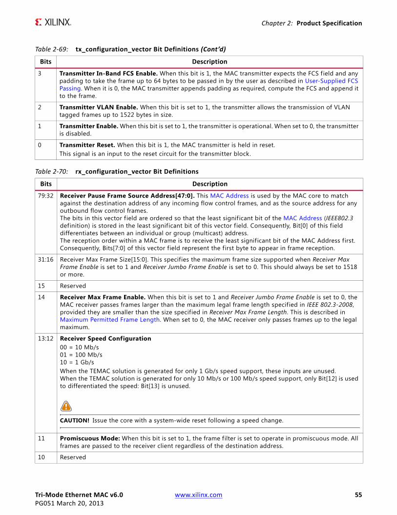
Tri-Mode Ethernet MAC v6.0 www.xilinx.com 55PG051 March 20, 2013
Chapter 2: Product Specification
.
3 Transmitter In-Band FCS Enable. When this bit is 1, the MAC transmitter expects the FCS f ield and any padding to take the frame up to 64 bytes to be passed in by the user as described in User-Supplied FCS Passing. When it is 0, the MAC transmitter appends padding as required, compute the FCS and append it to the frame.
2 Transmitter VLAN Enable. When this bit is set to 1, the transmitter allows the transmission of VLAN tagged frames up to 1522 bytes in size.
1 Transmitter Enable. When this bit is set to 1, the transmitter is operational. When set to 0, the transmitter is disabled.
0 Transmitter Reset. When this bit is 1, the MAC transmitter is held in reset.This signal is an input to the reset circuit for the transmitter block.
Table 2-69: tx_configuration_vector Bit Definitions (Cont’d)
Bits Description
Table 2-70: rx_configuration_vector Bit Definitions
Bits Description
79:32 Receiver Pause Frame Source Address[47:0]. This MAC Address is used by the MAC core to match against the destination address of any incoming flow control frames, and as the source address for any outbound flow control frames.The bits in this vector f ield are ordered so that the least signif icant bit of the MAC Address (IEEE802.3 definition) is stored in the least significant bit of this vector f ield. Consequently, Bit[0] of this f ield differentiates between an individual or group (multicast) address.The reception order within a MAC frame is to receive the least signif icant bit of the MAC Address f irst. Consequently, Bits[7:0] of this vector field represent the f irst byte to appear in frame reception.
31:16 Receiver Max Frame Size[15:0]. This specifies the maximum frame size supported when Receiver Max Frame Enable is set to 1 and Receiver Jumbo Frame Enable is set to 0. This should always be set to 1518 or more.
15 Reserved
14 Receiver Max Frame Enable. When this bit is set to 1 and Receiver Jumbo Frame Enable is set to 0, the MAC receiver passes frames larger than the maximum legal frame length specified in IEEE 802.3-2008, provided they are smaller than the size specified in Receiver Max Frame Length. This is described in Maximum Permitted Frame Length. When set to 0, the MAC receiver only passes frames up to the legal maximum.
13:12 Receiver Speed Configuration00 = 10 Mb/s01 = 100 Mb/s10 = 1 Gb/sWhen the TEMAC solution is generated for only 1 Gb/s speed support, these inputs are unused.When the TEMAC solution is generated for only 10 Mb/s or 100 Mb/s speed support, only Bit[12] is used to differentiated the speed: Bit[13] is unused.
CAUTION! Issue the core with a system-wide reset following a speed change.
11 Promiscuous Mode: When this bit is set to 1, the frame filter is set to operate in promiscuous mode. All frames are passed to the receiver client regardless of the destination address.
10 Reserved

Tri-Mode Ethernet MAC v6.0 www.xilinx.com 56PG051 March 20, 2013
Chapter 2: Product Specification
System RequirementsFor operating system requirements, see the Xilinx Design Tools: Release Notes Guide.
9 Receiver Control Frame Length Check Disable When this bit is set so 1, the core does not mark control frames as ‘bad’ if they are greater than the minimum frame length.
8 Receiver Length/Type Error Check Disable When this bit is 1, the core does not perform the length/type f ield error checks as described in Length/Type Field Error Checks. When it is set to 0, the length/type f ield checks are performed; this is normal operation.
7 Reserved
6 Receiver Half-Duplex If 1, the receiver operates in half-duplex mode. If 0, the receiver operates in full-duplex mode.If the TEMAC has been generated without half-duplex support then this input to the core is unused.
5 Receiver Flow Control Enable. When this bit is 1, received flow control frames inhibit the transmitter operation as described in Receiving a Pause Control Frame. When it is 0, received flow frames are passed up to the user.
4 Receiver Jumbo Frame Enable. When this bit is 1, the MAC receiver passes frames larger than the maximum legal frame length specified in IEEE 802.3-2008. When set to 0, the maximum frame size is dependent upon the setting of Receiver Max Frame Enable and Receiver Max Frame Length.
3 Receiver In-Band FCS Enable. When this bit is 1, the MAC receiver pass the FCS f ield to the user as described in User-Supplied FCS Passing. When it is 0, the MAC receiver does not pass the FCS f ield. In both cases, the FCS field is verif ied on the frame.
2 Receiver VLAN Enable. When this bit is set to 1, the receiver allows the reception of VLAN tagged frames up to 1522 bytes in size.
1 Receiver Enable. When this bit is set to 1, the receiver is operational. When set to 0, the receiver is disabled.
0 Receiver Reset. When this bit is 1, the MAC receiver is held in reset.This signal is an input to the reset circuit for the receiver block.
Table 2-70: rx_configuration_vector Bit Definitions (Cont’d)
Bits Description
Tri-Mode Ethernet MAC v6.0 www.xilinx.com 57PG051 March 20, 2013
Chapter 3
Designing with the CoreThis chapter includes guidelines and additional information to facilitate designing with the core.
General Design GuidelinesThis section describes the steps required to turn the TEMAC solution into a fully-functioning design integrated with user application logic.
IMPORTANT: It is important to recognize that not all designs require all the design steps defined in this chapter. The following sections discuss the design steps required for various implementations; follow the logic design guidelines carefully.
Design StepsGenerate the core using the Vivado™ Design Suite. See Chapter 4, Customizing and Generating the Core.
Using the Example Design as a Starting Point
The core is delivered through the Vivado Design Suite with an HDL example design built around the core, allowing the functionality of the core to be demonstrated using either a simulation package or in hardware, if placed on a suitable board. Figure 3-1 shows a block diagram of the example design. For details about the Vivado example design, see Chapter 6, Example Design.
The example design illustrates how to:
• Instantiate the core from HDL.
• Source and use the user-side interface ports of the core from application logic.
• Connect the physical-side interface of the core (GMII/MII or RGMII) to device IOBs creating an external interface. (See the Physical Interface chapters in this document)
• Derive the clock logic, required for the core (See the Physical Interface chapters in this document).
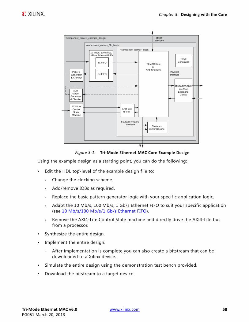
Tri-Mode Ethernet MAC v6.0 www.xilinx.com 58PG051 March 20, 2013
Chapter 3: Designing with the Core
X-Ref Target - Figure 3-1
Using the example design as a starting point, you can do the following:
• Edit the HDL top-level of the example design f ile to:
° Change the clocking scheme.
° Add/remove IOBs as required.
° Replace the basic pattern generator logic with your specif ic application logic.
° Adapt the 10 Mb/s, 100 Mb/s, 1 Gb/s Ethernet FIFO to suit your specif ic application (see 10 Mb/s/100 Mb/s/1 Gb/s Ethernet FIFO).
° Remove the AXI4-Lite Control State machine and directly drive the AXI4-Lite bus from a processor.
• Synthesize the entire design.
• Implement the entire design.
° After implementation is complete you can also create a bitstream that can be downloaded to a Xilinx device.
• Simulate the entire design using the demonstration test bench provided.
• Download the bitstream to a target device.
Figure 3-1: Tri-Mode Ethernet MAC Core Example Design
<component_name>_block
<component_name>_example_design
Pattern Generator& Checker
Physical Interface
<component_name>_fifo_block
Statistics Vectors Interface
ClockGeneration
MII/GMII/RGMIIInterfaceLogic and
Clocks
TEMAC Core&
AVB Endpoint
Tx FIFO
Rx FIFO
10 Mbps, 100 Mbps,1 Gbps Ethernet FIFO
InterfaceMDIO
StatisticsVector Decode
AXI4-Liteto IPIF
AXI4-LiteControlState
Machine
AVB Pattern
Generator& Checker
Tri-Mode Ethernet MAC v6.0 www.xilinx.com 59PG051 March 20, 2013
Chapter 3: Designing with the Core
Implementing the Tri-Mode Ethernet MACThe example design can be studied as an example of how to do the following:
• Instantiate the core from HDL.
• Source and use the user-side interface ports of the core from application logic.
• Connect the physical-side interface of the core (GMII/MII or RGMII) to device IOBs to create an external interface.
• Derive the required clock logic.
After working with the example design and this product guide, you can write your own HDL application, using single or multiple instances of the core.
Care must be taken to constrain the design correctly, and the constraints provided with the core should be used as the basis for the your own. For Vivado Design Suite constraints, see Chapter 5, Constraining the Core.
You can simulate the entire design and download the bitstream to the target device.
Keep it RegisteredTo simplify timing and increase system performance in an FPGA design, keep all inputs and outputs registered between your application and the core. This means that all inputs and outputs from your application should come from, or connect to, a flip-flop. While registering signals might not be possible for all paths, it simplif ies timing analysis and makes it easier for the Xilinx tools to place-and-route the design.
Recognize Timing Critical SignalsThe constraints provided with the example design identif ies the critical signals and timing constraints that should be applied. For Vivado Design Suite constraints, see Chapter 5, Constraining the Core.
Make Only Allowed ModificationsYou should not modify the core. Any modifications can have adverse effects on system timing and protocol compliance. Supported user configurations of the core can only be made by selecting the options in the customization GUI when the core is generated. For Vivado Design Suite, see Chapter 4, Customizing and Generating the Core.
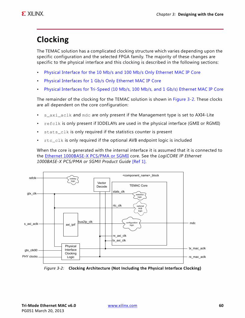
Tri-Mode Ethernet MAC v6.0 www.xilinx.com 60PG051 March 20, 2013
Chapter 3: Designing with the Core
ClockingThe TEMAC solution has a complicated clocking structure which varies depending upon the specific configuration and the selected FPGA family. The majority of these changes are specific to the physical interface and this clocking is described in the following sections:
• Physical Interface for the 10 Mb/s and 100 Mb/s Only Ethernet MAC IP Core
• Physical Interfaces for 1 Gb/s Only Ethernet MAC IP Core
• Physical Interfaces for Tri-Speed (10 Mb/s, 100 Mb/s, and 1 Gb/s) Ethernet MAC IP Core
The remainder of the clocking for the TEMAC solution is shown in Figure 3-2. These clocks are all dependent on the core configuration:
• s_axi_aclk and mdc are only present if the Management type is set to AXI4-Lite
• refclk is only present if IODELAYs are used in the physical interface (GMII or RGMII)
• stats_clk is only required if the statistics counter is present
• rtc_clk is only required if the optional AVB endpoint logic is included
When the core is generated with the internal interface it is assumed that it is connected to the Ethernet 1000BASE-X PCS/PMA or SGMII core. See the LogiCORE IP Ethernet 1000BASE-X PCS/PMA or SGMII Product Guide [Ref 1].
X-Ref Target - Figure 3-2
Figure 3-2: Clocking Architecture (Not Including the Physical Interface Clocking)

Tri-Mode Ethernet MAC v6.0 www.xilinx.com 61PG051 March 20, 2013
Chapter 3: Designing with the Core
ResetsDue to the number of clock domains in this IP core the reset structure is not simple and involves many separate reset regions, with the number of regions being dependent upon the particular parameterization of the core.
Figure 3-3 shows the most common reset structure for the core. Because the rx_reset and tx_reset outputs have dependencies on the glbl_rstn and the tx/rx_axi_rstn inputs they cannot be used in their creation.
X-Ref Target - Figure 3-3
Figure 3-3: Reset Architecture

Tri-Mode Ethernet MAC v6.0 www.xilinx.com 62PG051 March 20, 2013
Chapter 3: Designing with the Core
Protocol Description
Ethernet Protocol OverviewThis section gives an overview of where the Ethernet MAC fits into an Ethernet system and provides a description of some basic Ethernet terminology.
Ethernet Sublayer Architecture
Figure 3-4 illustrates the relationship between the Open Systems Interconnection (OSI) reference model and the Ethernet MAC, as defined in [Ref 8]. The grayed-in layers show the functionality that the Ethernet MAC handles. Figure 3-4 also shows where the supported physical interfaces fit into the architecture.
X-Ref Target - Figure 3-4
Figure 3-4: IEEE Std 802.3-2008 Ethernet Model
PCSPMA
OSIReference
ModelLayers
Application
Presentation
Session
Transport
Network
Data Link
PHY - Physical
LLC-Logical Link Control
MAC Control (Optional)
MAC - Media Access Control
Reconciliation
PMD
Medium
LANCSMA/CD
Layers
Higher Layers
PMD - Physical Medium Dependent
PMA - Physical Medium Attachment
PCS - Physical Coding Sublayer
PCSPMAPMD
Medium
1000BASE-X(for example, Optical Fiber Medium)
1000BASE-T100BASE-T10BASE-T
(for example, Copper Medium)
GMII/MIIRGMIISGMII
RGMII - Reduced Gigabit Media Independent Interface
GMII - Gigabit Media Independent Interface
MII - Media Independent Interface
SGMII - Serial Gigabit Media Independent Interface

Tri-Mode Ethernet MAC v6.0 www.xilinx.com 63PG051 March 20, 2013
Chapter 3: Designing with the Core
MAC and MAC CONTROL Sublayer
The Ethernet MAC is defined in IEEE Std 802.3-2008, clauses 2, 3, and 4. A MAC is responsible for the Ethernet framing protocols described in Ethernet Data Format and error detection of these frames. The MAC is independent of and can connect to any type of physical layer device.
The MAC CONTROL sublayer is defined in IEEE Std 802.3-2008, clause 31. This provides real-time flow control manipulation of the MAC sublayer.
Both the MAC CONTROL and MAC sublayers are provided by the Ethernet MAC in all modes of operation.
Physical Sublayers PCS, PMA, and PMD
The combination of the Physical Coding Sublayer (PCS), the Physical Medium Attachment (PMA), and the Physical Medium Dependent (PMD) sublayer constitute the physical layers for the protocol. Two main physical standards are specified:
• BASE-T PHYs provide a link between the MAC and copper mediums. This functionality is not offered within the TEMAC. However, external BASE-T PHY devices are readily available on the market. These can connect to the Ethernet MAC, using GMII/MII, RGMII, or, by additionally using the Ethernet 1000BASE-X PCS/PMA or SGMII LogiCORE, SGMII interfaces.
• BASE-X PHYs provide a link between the MAC and (usually) f iber optic mediums. The TEMAC is capable of supporting the 1 Gb/s BASE-X standard; 1000BASE-X PCS and PMA sublayers can be offered by connecting the TEMAC to the Ethernet 1000BASE-X PCS/PMA or SGMII LogiCORE.
Ethernet Data Format
Ethernet data is encapsulated in frames, as shown in Figure 3-5, for standard Ethernet frames. The f ields in the frame are transmitted from left to right. The bytes within the fields are transmitted from left to right (from least significant bit to most signif icant bit unless specified otherwise). The Ethernet MAC can handle jumbo Ethernet frames where the data f ield can be much larger than 1,500 bytes.
The Ethernet MAC can also accept Virtual LAN (VLAN) frames. The VLAN frame format is shown in Figure 3-6. If the frame is a VLAN type frame, the Ethernet MAC accepts four additional bytes.
X-Ref Target - Figure 3-5
Figure 3-5: Standard Ethernet Frame Format
Preamble Start of Frame Delimiter (SFD)
Destination Address
Source Address
Length/Type
Data Pad
64 - 1518 Bytes
7 1 6 6 2 0 - 1500 0 - 46 4Number of Bytes
FCS
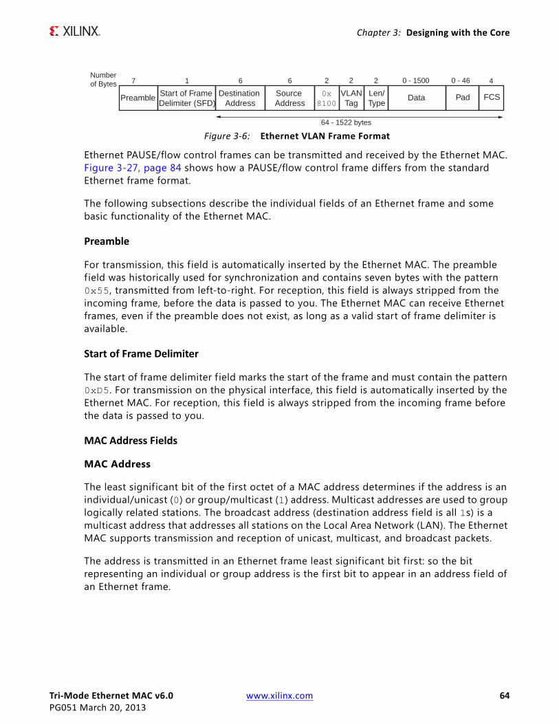
Tri-Mode Ethernet MAC v6.0 www.xilinx.com 64PG051 March 20, 2013
Chapter 3: Designing with the Core
.
Ethernet PAUSE/flow control frames can be transmitted and received by the Ethernet MAC. Figure 3-27, page 84 shows how a PAUSE/flow control frame differs from the standard Ethernet frame format.
The following subsections describe the individual f ields of an Ethernet frame and some basic functionality of the Ethernet MAC.
Preamble
For transmission, this f ield is automatically inserted by the Ethernet MAC. The preamble f ield was historically used for synchronization and contains seven bytes with the pattern 0x55, transmitted from left-to-right. For reception, this f ield is always stripped from the incoming frame, before the data is passed to you. The Ethernet MAC can receive Ethernet frames, even if the preamble does not exist, as long as a valid start of frame delimiter is available.
Start of Frame Delimiter
The start of frame delimiter f ield marks the start of the frame and must contain the pattern 0xD5. For transmission on the physical interface, this f ield is automatically inserted by the Ethernet MAC. For reception, this f ield is always stripped from the incoming frame before the data is passed to you.
MAC Address Fields
MAC Address
The least significant bit of the f irst octet of a MAC address determines if the address is an individual/unicast (0) or group/multicast (1) address. Multicast addresses are used to group logically related stations. The broadcast address (destination address field is all 1s) is a multicast address that addresses all stations on the Local Area Network (LAN). The Ethernet MAC supports transmission and reception of unicast, multicast, and broadcast packets.
The address is transmitted in an Ethernet frame least significant bit f irst: so the bit representing an individual or group address is the first bit to appear in an address field of an Ethernet frame.
X-Ref Target - Figure 3-6
Figure 3-6: Ethernet VLAN Frame Format
Preamble Start of Frame Delimiter (SFD)
Destination Address
Source Address
0x8100
Data Pad
64 - 1522 bytes
7 1 6 6 2 0 - 1500 0 - 46 4Number of Bytes
FCS
2 2
Len/Type
VLANTag
Tri-Mode Ethernet MAC v6.0 www.xilinx.com 65PG051 March 20, 2013
Chapter 3: Designing with the Core
Destination Address
This MAC Address f ield is the f irst f ield of the Ethernet frame that is always provided in the packet data for transmissions and is always retained in the receive packet data. It provides the MAC address of the intended recipient on the network.
Source Address
This MAC Address field is the second field of the Ethernet frame that is always provided in the packet data for transmissions and is always retained in the receive packet data. It provides the MAC address of the frame initiator on the network.
For transmission, the source address of the Ethernet frame should always be provided by you because it is unmodified by the TEMAC.
Length/Type
The value of this f ield determines if it is interpreted as a length or a type f ield, as defined by IEEE Std 802.3-2008. A value of 1,536 decimal or greater is interpreted by the Ethernet MAC as a type f ield.
When used as a length field, the value in this f ield represents the number of bytes in the following data field. This value does not include any bytes that can be inserted in the pad f ield following the data f ield.
A length/type f ield value of 0x8100 indicates that the frame is a VLAN frame, and a value of 0x8808 indicates a PAUSE MAC control frame.
For transmission, the Ethernet MAC does not perform any processing of the length/type f ield.
For reception, if this f ield is a length field, the Ethernet MAC receive engine interprets this value and removes any padding in the pad f ield (if necessary). If the f ield is a length field and length/type checking is enabled, the Ethernet MAC compares the length against the actual data f ield length and flags an error if a mismatch occurs. If the f ield is a type f ield, the Ethernet MAC ignores the value and passes it along with the packet data with no further processing. The length/type f ield is always retained in the receive packet data.
Data
The data f ield can vary from 0 to 1,500 bytes in length for a normal frame. The Ethernet MAC can handle jumbo frames of any length.
This f ield is always provided in the packet data for transmissions and is always retained in the receive packet data.
Tri-Mode Ethernet MAC v6.0 www.xilinx.com 66PG051 March 20, 2013
Chapter 3: Designing with the Core
Pad
The pad field can vary from 0 to 46 bytes in length. This f ield is used to ensure that the frame length is at least 64 bytes in length (the preamble and SFD fields are not considered part of the frame for this calculation), which is required for successful CSMA/CD operation. The values in this f ield are used in the frame check sequence calculation but are not included in the length f ield value, if it is used. The length of this f ield and the data field combined must be at least 46 bytes. If the data field contains 0 bytes, the pad field is 46 bytes. If the data field is 46 bytes or more, the pad f ield has 0 bytes.
For transmission, this f ield can be inserted automatically by the Ethernet MAC or supplied by you. If the pad f ield is inserted by the Ethernet MAC, the FCS field is calculated and inserted by the Ethernet MAC. If the pad field is supplied by you, the FCS can either be inserted by the Ethernet MAC or provided by you, as indicated by a configuration register bit.
For reception, if the length/type field has a length interpretation, any pad f ield in the incoming frame is not passed to you, unless the Ethernet MAC is configured to pass the FCS f ield on to you.
FCS
The value of the FCS field is calculated over the destination address, source address, length/type, data, and pad f ields using a 32-bit Cyclic Redundancy Check (CRC), as defined in IEEE Std 802.3-2008 para. 3.2.8:
G(x) = x32 + x26 + x23 + x22 + x16 + x12 + x11 + x10 + x8 + x7 + x5 + x4 + x2 + x1 + x0
The CRC bits are placed in the FCS field with the x31 term in the left-most bit of the f irst byte, and the x0 term is the right-most bit of the last byte (that is, the bits of the CRC are transmitted in the order x31, x30,..., x1, x0).
For transmission, this f ield can be inserted automatically by the Ethernet MAC or supplied by you, as indicated by a configuration register bit.
For reception, the incoming FCS value is verif ied on every frame. If an incorrect FCS value is received, the Ethernet MAC indicates to you that it has received a bad frame. The FCS f ield can either be passed on to you or be dropped by the Ethernet MAC, as indicated by a configuration register bit.
Frame Transmission and Interframe Gap
Frames are transmitted over the Ethernet medium with an interframe gap, as specified by the IEEE Std 802.3-2008, to be 96-bit times (9.6 µs for 10 Mb/s, 0.96 µs for 100 Mb/s, and 96 ns for 1 Gb/s). This value is a minimum and can be increased with a resulting decrease in throughput. The process for frame transmission is different for half-duplex and full-duplex systems.
Tri-Mode Ethernet MAC v6.0 www.xilinx.com 67PG051 March 20, 2013
Chapter 3: Designing with the Core
Half-Duplex Frame Transmission
In a half-duplex system, the CSMA/CD media access method defines how two or more stations share a common medium.
1. Even when it has nothing to transmit, the Ethernet MAC monitors the Ethernet medium for traff ic by watching the carrier sense signal (CRS) from the external PHY. Whenever the medium is busy (CRS = 1), the Ethernet MAC defers to the passing frame by delaying any pending transmission of its own.
2. After the last bit of the passing frame (when the carrier sense signal changes from TRUE to FALSE), the Ethernet MAC starts the timing of the interframe gap.
3. The Ethernet MAC resets the interframe gap timer if the carrier sense becomes TRUE during the period defined by “interframe gap part 1 (IFG1).” IEEE Std 802.3-2008 states that this should be the first 2/3 of the interframe gap timing interval (64-bit times) but can be shorter and as small as zero. The purpose of this option is to support a possible brief failure of the carrier sense signal during a collision condition and is described in paragraph 4.2.3.2.1 of the IEEE standard.
4. The Ethernet MAC does not reset the interframe gap timer if carrier sense becomes TRUE during the period defined by “interframe gap part 2 (IFG2)” to ensure fair access to the bus. IEEE Std 802.3-2008 states that this should be the last 1/3 of the interframe gap timing interval.
If, after initiating a transmission, the message collides with the message of another station (COL = 1), then each transmitting station intentionally continues to transmit (jam) for an additional predefined period (32-bit times for 10/100 Mb/s) to ensure propagation of the collision throughout the system. The station remains silent for a random amount of time (back off) before attempting to transmit again.
A station can experience a collision during the beginning of its transmission (the collision window) before its transmission has had time to propagate to all stations on the bus. After the collision window has passed, a transmitting station has acquired the bus. Subsequent collisions (late collisions) are avoided because all other (properly functioning) stations are assumed to have detected the transmission and are deferring to it.
Full-Duplex Frame Transmission
In a full-duplex system, there is a point-to-point dedicated connection between two Ethernet devices, capable of simultaneous transmit and receive with no possibility of collisions. The Ethernet MAC does not use the carrier sense signal from the external PHY because the medium is not shared, and the Ethernet MAC only needs to monitor its own transmissions. After the last bit of an Ethernet MAC frame transmission, the Ethernet MAC starts the interframe gap timer and defers transmissions until the IFG count completes. The minimum value supported for the IFG depends on the TEMAC solution options and the current mode of operation.
Tri-Mode Ethernet MAC v6.0 www.xilinx.com 68PG051 March 20, 2013
Chapter 3: Designing with the Core
If the TEMAC solution has been built with half-duplex support then the IFG delay is 96-bit times, or when IFG Adjustment is enabled, the greater of 64-bit times, and the value presented on tx_ifg_delay.
If the TEMAC solution has been built with only full-duplex support then the IFG delay is 96-bit times, or when IFG Adjustment is enabled, the greater of 32-bit times, and the value presented on tx_ifg_delay.
AXI4-Stream User InterfaceThis section provides a detailed description of the AXI4-Stream user-side interface. This interface must be used by the user-side logic to initiate frame transmission and accept frame reception to and from the core. The definitions and abbreviations used in this chapter are described in Table 3-1.
.
Receiving Inbound FramesReceived Ethernet frames are presented to the user logic on the receiver subset of the AXI4-Stream interface. For port definition, see Receiver Interface. All receiver signals are synchronous to the rx_mac_aclk clock.
Normal Frame Reception
Figure 3-7 shows the timing of a normal inbound frame transfer at 1 Gb/s. Figure 3-8 shows the timing at 10/100 Mb/s when the core is configured for MII/GMII or RGMII, For the Internal option the timing for 100 Mb/s is shown in Figure 3-9, for 10 Mb/s the rx_axis_mac_tvalid is only enabled once every 100 cycles. You must be prepared to accept data at any time; there is no buffering within the MAC to allow for latency in the receive logic. When frame reception begins, data is transferred on consecutive validated cycles to the receive logic until the frame is complete. The MAC asserts the rx_axis_mac_tlast signal to indicate that the frame has completed with rx_axis_mac_tuser being used to indicate any errors.
Table 3-1: Abbreviations Used in Timing Diagrams
Abbreviation Definition
DA Destination address; 6 bytes
SA Source address; 6 bytes
L/T Length/type f ield; 2 bytes
FCS Frame check sequence; 4 bytes
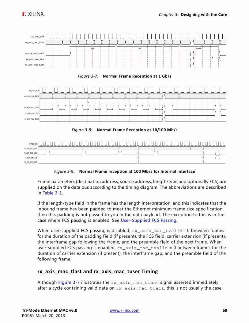
Tri-Mode Ethernet MAC v6.0 www.xilinx.com 69PG051 March 20, 2013
Chapter 3: Designing with the Core
Frame parameters (destination address, source address, length/type and optionally FCS) are supplied on the data bus according to the timing diagram. The abbreviations are described in Table 3-1.
If the length/type field in the frame has the length interpretation, and this indicates that the inbound frame has been padded to meet the Ethernet minimum frame size specif ication, then this padding is not passed to you in the data payload. The exception to this is in the case where FCS passing is enabled. See User-Supplied FCS Passing.
When user-supplied FCS passing is disabled, rx_axis_mac_tvalid= 0 between frames for the duration of the padding f ield (if present), the FCS field, carrier extension (if present), the interframe gap following the frame, and the preamble field of the next frame. When user-supplied FCS passing is enabled, rx_axis_mac_tvalid = 0 between frames for the duration of carrier extension (if present), the interframe gap, and the preamble field of the following frame.
rx_axis_mac_tlast and rx_axis_mac_tuser Timing
Although Figure 3-7 illustrates the rx_axis_mac_tlast signal asserted immediately after a cycle containing valid data on rx_axis_mac_tdata, this is not usually the case.
X-Ref Target - Figure 3-7
Figure 3-7: Normal Frame Reception at 1 Gb/s
rx_mac_aclk
rx_axis_mac_tdata
rx_axis_mac_tvalid
rx_axis_mac_tlast
rx_axis_mac_tuser
DA SA L/T DATA
X-Ref Target - Figure 3-8
Figure 3-8: Normal Frame Reception at 10/100 Mb/s
rx_mac_aclk
rx_axis_mac_tdata
rx_axis_mac_tvalid
rx_axis_mac_ltast
tx_axis_mac_tuser
DA
X-Ref Target - Figure 3-9
Figure 3-9: Normal Frame reception at 100 Mb/s for Internal interface
rx_mac_aclk
rx_axis_mac_tdata
rx_axis_mac_tvalid
rx_axis_mac_ltast
rx_axis_mac_tuser

Tri-Mode Ethernet MAC v6.0 www.xilinx.com 70PG051 March 20, 2013
Chapter 3: Designing with the Core
The rx_axis_mac_tlast and rx_axis_mac_tuser signals are asserted, along with the f inal byte of the transfer, only after all frame checks are completed. This is after the FCS f ield has been received (and after reception of carrier extension, if present). This is shown in Figure 3-10.
Therefore, rx_axis_mac_tlast and possibly rx_axis_mac_tuser are asserted following frame reception at the beginning of the interframe gap.
Frame Reception with Errors
Figure 3-11 illustrates an unsuccessful frame reception (for example, a fragment frame or a frame with an incorrect FCS). In this case, the rx_axis_mac_tuser signal is asserted to you at the end of the frame. It is your responsibility to drop the data already transferred for this frame.
The following conditions cause the assertion of rx_axis_mac_tuser:
• FCS errors occur.
• Packets are shorter than 64 bytes (undersize or fragment frames).
• Jumbo frames are received when jumbo frames are not enabled.
• VLAN frames of length 1,519-1,522 are received when VLAN frames are not enabled.
• A frame above the programmed Maximum Frame Size is received when Maximum Frame Length checking is enabled.
X-Ref Target - Figure 3-10
Figure 3-10: Frame Reception TLast Timing
rx_mac_aclk
rx_axis_mac_tdata
rx_axis_mac_tvalid
rx_axis_mac_tlast
rx_axis_mac_tuser
X-Ref Target - Figure 3-11
Figure 3-11: Frame Reception with Error
rx_mac_aclk
rx_axis_mac_tdata
rx_axis_mac_tvalid
rx_axis_mac_tlast
rx_axis_mac_tuser
DA SA L/T DATA
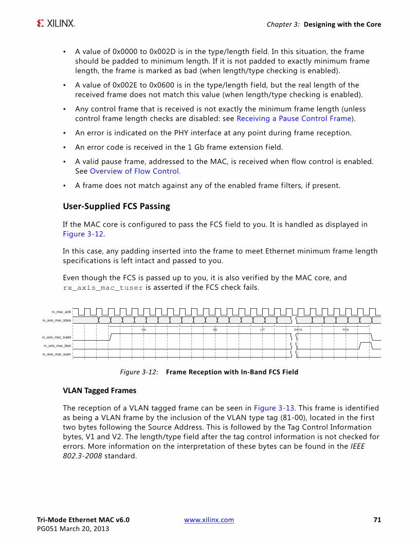
Tri-Mode Ethernet MAC v6.0 www.xilinx.com 71PG051 March 20, 2013
Chapter 3: Designing with the Core
• A value of 0x0000 to 0x002D is in the type/length field. In this situation, the frame should be padded to minimum length. If it is not padded to exactly minimum frame length, the frame is marked as bad (when length/type checking is enabled).
• A value of 0x002E to 0x0600 is in the type/length field, but the real length of the received frame does not match this value (when length/type checking is enabled).
• Any control frame that is received is not exactly the minimum frame length (unless control frame length checks are disabled: see Receiving a Pause Control Frame).
• An error is indicated on the PHY interface at any point during frame reception.
• An error code is received in the 1 Gb frame extension f ield.
• A valid pause frame, addressed to the MAC, is received when flow control is enabled. See Overview of Flow Control.
• A frame does not match against any of the enabled frame filters, if present.
User-Supplied FCS Passing
If the MAC core is configured to pass the FCS field to you. It is handled as displayed in Figure 3-12.
In this case, any padding inserted into the frame to meet Ethernet minimum frame length specifications is left intact and passed to you.
Even though the FCS is passed up to you, it is also verif ied by the MAC core, and rx_axis_mac_tuser is asserted if the FCS check fails.
VLAN Tagged Frames
The reception of a VLAN tagged frame can be seen in Figure 3-13. This frame is identif ied as being a VLAN frame by the inclusion of the VLAN type tag (81-00), located in the first two bytes following the Source Address. This is followed by the Tag Control Information bytes, V1 and V2. The length/type f ield after the tag control information is not checked for errors. More information on the interpretation of these bytes can be found in the IEEE 802.3-2008 standard.
X-Ref Target - Figure 3-12
Figure 3-12: Frame Reception with In-Band FCS Field
rx_mac_aclk
rx_axis_mac_tdata
rx_axis_mac_tvalid
rx_axis_mac_tlast
rx_axis_mac_tuser
DA SA L/T DATA FCS
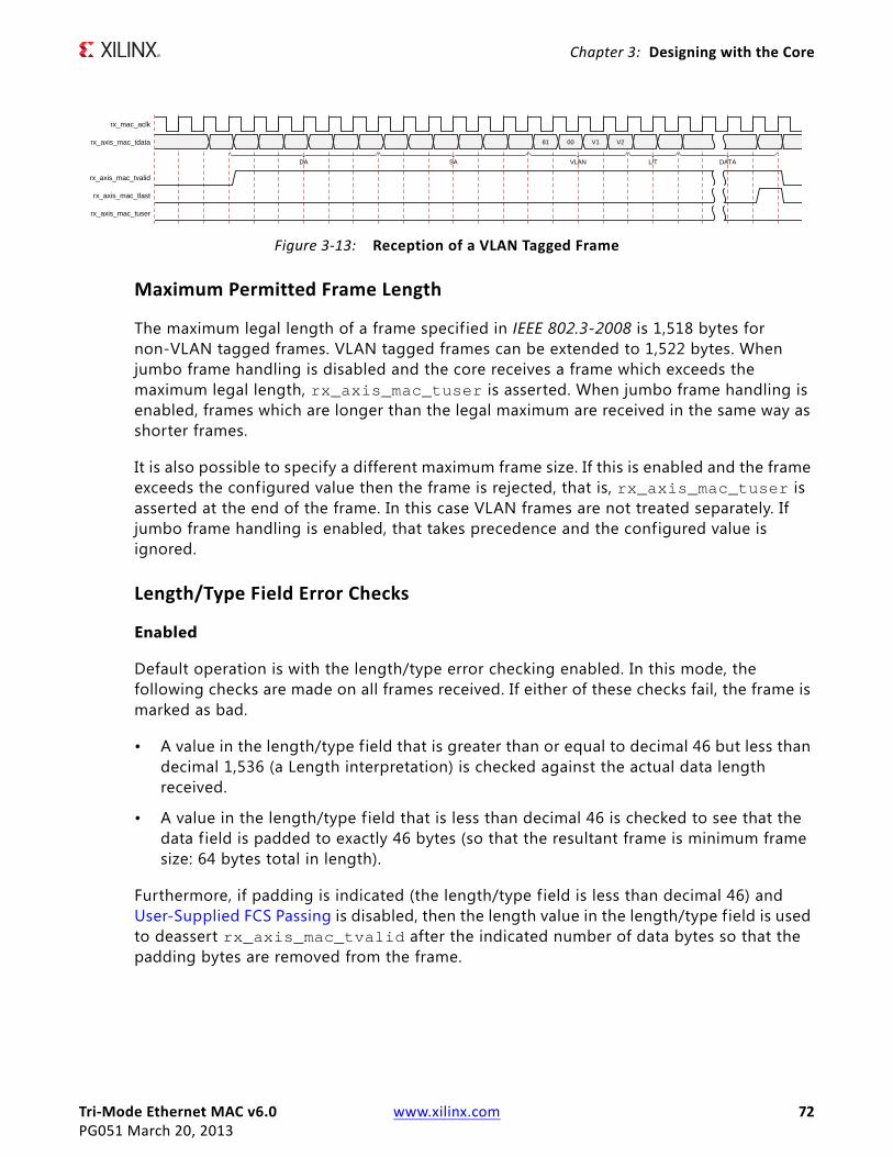
Tri-Mode Ethernet MAC v6.0 www.xilinx.com 72PG051 March 20, 2013
Chapter 3: Designing with the Core
Maximum Permitted Frame Length
The maximum legal length of a frame specified in IEEE 802.3-2008 is 1,518 bytes for non-VLAN tagged frames. VLAN tagged frames can be extended to 1,522 bytes. When jumbo frame handling is disabled and the core receives a frame which exceeds the maximum legal length, rx_axis_mac_tuser is asserted. When jumbo frame handling is enabled, frames which are longer than the legal maximum are received in the same way as shorter frames.
It is also possible to specify a different maximum frame size. If this is enabled and the frame exceeds the configured value then the frame is rejected, that is, rx_axis_mac_tuser is asserted at the end of the frame. In this case VLAN frames are not treated separately. If jumbo frame handling is enabled, that takes precedence and the configured value is ignored.
Length/Type Field Error Checks
Enabled
Default operation is with the length/type error checking enabled. In this mode, the following checks are made on all frames received. If either of these checks fail, the frame is marked as bad.
• A value in the length/type f ield that is greater than or equal to decimal 46 but less than decimal 1,536 (a Length interpretation) is checked against the actual data length received.
• A value in the length/type f ield that is less than decimal 46 is checked to see that the data field is padded to exactly 46 bytes (so that the resultant frame is minimum frame size: 64 bytes total in length).
Furthermore, if padding is indicated (the length/type field is less than decimal 46) and User-Supplied FCS Passing is disabled, then the length value in the length/type field is used to deassert rx_axis_mac_tvalid after the indicated number of data bytes so that the padding bytes are removed from the frame.
X-Ref Target - Figure 3-13
Figure 3-13: Reception of a VLAN Tagged Frame
rx_mac_aclk
rx_axis_mac_tdata
rx_axis_mac_tvalid
rx_axis_mac_tlast
rx_axis_mac_tuser
81 00 V1 V2
DA SA VLAN L/T DATA

Tri-Mode Ethernet MAC v6.0 www.xilinx.com 73PG051 March 20, 2013
Chapter 3: Designing with the Core
Disabled
When the length/type error checking is disabled and the length/type f ield has a length interpretation, the MAC does not check the length value against the actual data length received. A frame containing only this error is marked as good. However, if the length/type f ield is less than decimal 46, the MAC marks a frame as bad if it is not the minimum frame size of 64 bytes.
Furthermore, if padding is indicated and User-Supplied FCS Passing is disabled, then a length value in the length/type f ield is not used to deassert rx_axis_mac_tvalid. Instead rx_axis_mac_tvalid is deasserted before the start of the FCS f ield; in this way any padding is not removed from the frame.
Frame Filter
If the optional frame filter is included in the core, the MAC is able to reject frames that do not match against a recognized pattern, that is, a specif ied destination address. If a frame is rejected within the destination address, the rx_axis_mac_tvalid signal is not asserted for the duration of the frame. The statistics vectors are still output with a valid pulse at the end of the rejected frame. If a frame is not rejected during the destination address then rx_axis_mac_tvalid is asserted as normal through the frame though the frame can still be rejected at a later point through the assertion of rx_axis_mac_tuser at the end of the frame. This is described in more detail in Frame Filter.
Receiver Statistics Vector
The statistics for the frame received are contained within the rx_statistics_vector output. Table 3-2 defines the bit f ield for the vector.
All bit f ields, with the exception of BYTE_VALID are valid only when the rx_statistics_valid is asserted, as illustrated in Figure 3-14. BYTE_VALID is signif icant on every validated receiver cycle.
X-Ref Target - Figure 3-14
Figure 3-14: Receiver Statistics Vector Timing
rx_statistics_valid
rx_statistics_vector
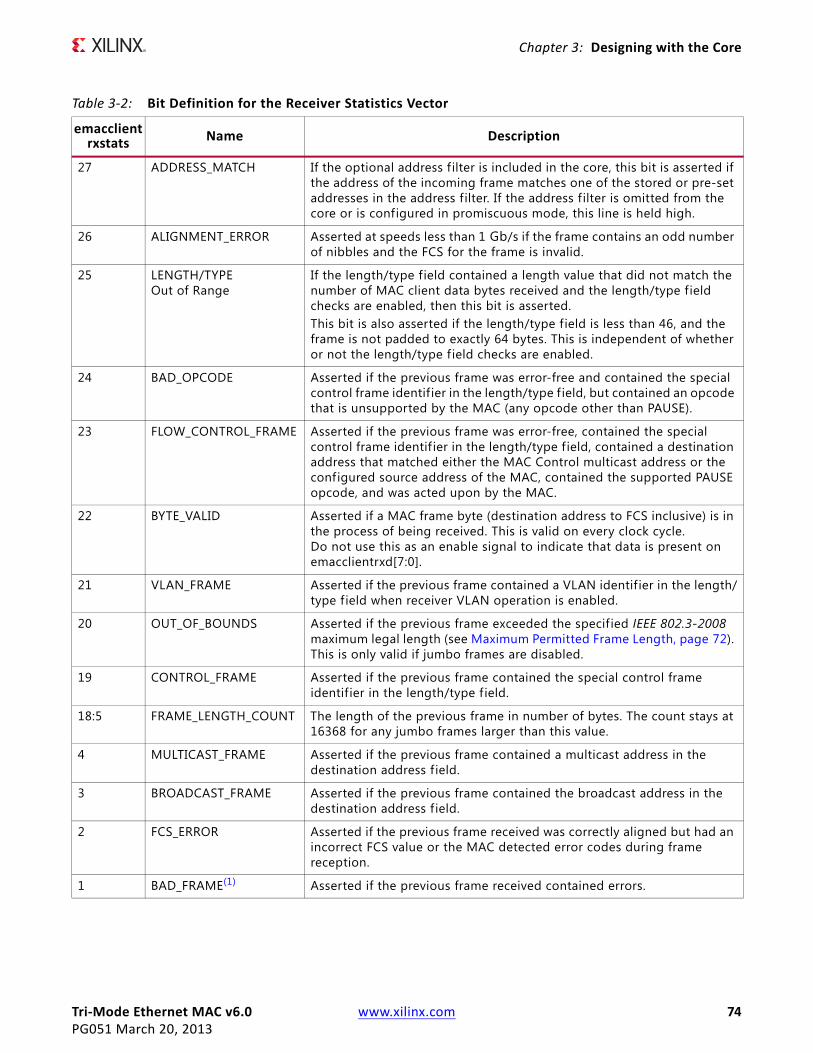
Tri-Mode Ethernet MAC v6.0 www.xilinx.com 74PG051 March 20, 2013
Chapter 3: Designing with the Core
Table 3-2: Bit Definition for the Receiver Statistics Vector
emacclientrxstats Name Description
27 ADDRESS_MATCH If the optional address filter is included in the core, this bit is asserted if the address of the incoming frame matches one of the stored or pre-set addresses in the address filter. If the address filter is omitted from the core or is configured in promiscuous mode, this line is held high.
26 ALIGNMENT_ERROR Asserted at speeds less than 1 Gb/s if the frame contains an odd number of nibbles and the FCS for the frame is invalid.
25 LENGTH/TYPEOut of Range
If the length/type field contained a length value that did not match the number of MAC client data bytes received and the length/type field checks are enabled, then this bit is asserted.This bit is also asserted if the length/type field is less than 46, and the frame is not padded to exactly 64 bytes. This is independent of whether or not the length/type f ield checks are enabled.
24 BAD_OPCODE Asserted if the previous frame was error-free and contained the special control frame identif ier in the length/type f ield, but contained an opcode that is unsupported by the MAC (any opcode other than PAUSE).
23 FLOW_CONTROL_FRAME Asserted if the previous frame was error-free, contained the special control frame identif ier in the length/type f ield, contained a destination address that matched either the MAC Control multicast address or the configured source address of the MAC, contained the supported PAUSE opcode, and was acted upon by the MAC.
22 BYTE_VALID Asserted if a MAC frame byte (destination address to FCS inclusive) is in the process of being received. This is valid on every clock cycle. Do not use this as an enable signal to indicate that data is present on emacclientrxd[7:0].
21 VLAN_FRAME Asserted if the previous frame contained a VLAN identif ier in the length/type f ield when receiver VLAN operation is enabled.
20 OUT_OF_BOUNDS Asserted if the previous frame exceeded the specified IEEE 802.3-2008 maximum legal length (see Maximum Permitted Frame Length, page 72). This is only valid if jumbo frames are disabled.
19 CONTROL_FRAME Asserted if the previous frame contained the special control frame identif ier in the length/type f ield.
18:5 FRAME_LENGTH_COUNT The length of the previous frame in number of bytes. The count stays at 16368 for any jumbo frames larger than this value.
4 MULTICAST_FRAME Asserted if the previous frame contained a multicast address in the destination address f ield.
3 BROADCAST_FRAME Asserted if the previous frame contained the broadcast address in the destination address f ield.
2 FCS_ERROR Asserted if the previous frame received was correctly aligned but had an incorrect FCS value or the MAC detected error codes during frame reception.
1 BAD_FRAME(1) Asserted if the previous frame received contained errors.
Tri-Mode Ethernet MAC v6.0 www.xilinx.com 75PG051 March 20, 2013
Chapter 3: Designing with the Core
Transmitting Outbound FramesEthernet frames to be transmitted are presented to the user logic on the transmitter subset of the AXI4-Stream user-side interface. For port definition, see Transmitter Interface. All transmitter signals are synchronous to the tx_mac_aclk clock if present or gtx_clk if not.
Normal Frame Transmission
The timing of a normal outbound frame transfer a 1 Gb/s can be seen in Figure 3-15, with the timing at 100 Mb/s shown in Figure 3-16 and Figure 3-17. When you want to transmit a frame, it places the first column of data onto the tx_axis_mac_tdata port and asserts a 1 onto tx_axis_mac_tvalid.
The TEMAC core accepts the f irst two bytes of data by asserting tx_axis_mac_tready and then waits until it is allowed to transmit and it then accepts the remainder of the frame. You must be capable of supplying new data on the following cycle when data has been taken, indicated by the assertion of tx_axis_mac_tready. The end of frame is signalled to the MAC core by asserting tx_axis_mac_tlast on the final byte of the frame.
At 1 Gb/s, data can be taken every 8 ns; at 100 Mb/s, data is taken, on average, every 80 ns; at 10 Mb/s, data is taken, on average, every 800 ns. In all cases tx_axis_mac_tready qualif ies when data is taken by the MAC. Figure 3-16 shows the use of tx_axis_mac_tready to throttle the data when the core has been generated with either an MII or GMII interface, in this mode the timing at 100 Mb/s and 10 Mb/s is identical as tx_mac_aclk is sourced by the PHY at the required frequency (25 MHz or 2.5 MHz).
When the core is generated with an RGMII interface or the Internal interface the timing at 10/100 Mb/s is very different as shown in Figure 3-17. In this mode the tx_mac_aclk remains at 125 MHz at all MAC speeds and the tx_axis_mac_tready is activated once every 10 cycles as shown in Figure 3-17 or once every 100 cycles at 10 Mb/s. This is not true for the f irst 2 bytes of frame data where the data pipeline f ills at full rate.
For maximum flexibility in switching applications, the Ethernet frame parameters (destination address, source address, length/type and optionally FCS) are encoded within the same data stream that the frame payload is transferred upon, rather than on separate ports.
0 GOOD_FRAME(1) Asserted if the previous frame received was error-free.1. If the length/type f ield error checks are disabled, a frame which has an actual data length that does not match the length/
type f ield value is marked as a GOOD_FRAME providing no additional errors were detected. See Length/Type Field Error Checks, page 72.
Table 3-2: Bit Definition for the Receiver Statistics Vector (Cont’d)
emacclientrxstats Name Description
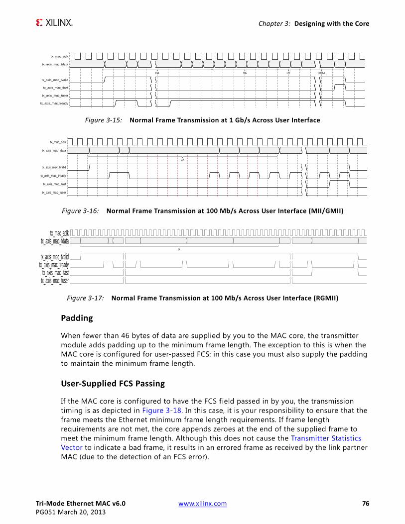
Tri-Mode Ethernet MAC v6.0 www.xilinx.com 76PG051 March 20, 2013
Chapter 3: Designing with the Core
Padding
When fewer than 46 bytes of data are supplied by you to the MAC core, the transmitter module adds padding up to the minimum frame length. The exception to this is when the MAC core is configured for user-passed FCS; in this case you must also supply the padding to maintain the minimum frame length.
User-Supplied FCS Passing
If the MAC core is configured to have the FCS field passed in by you, the transmission timing is as depicted in Figure 3-18. In this case, it is your responsibility to ensure that the frame meets the Ethernet minimum frame length requirements. If frame length requirements are not met, the core appends zeroes at the end of the supplied frame to meet the minimum frame length. Although this does not cause the Transmitter Statistics Vector to indicate a bad frame, it results in an errored frame as received by the link partner MAC (due to the detection of an FCS error).
X-Ref Target - Figure 3-15
Figure 3-15: Normal Frame Transmission at 1 Gb/s Across User Interface
tx_mac_aclk
tx_axis_mac_tdata
tx_axis_mac_tvalid
tx_axis_mac_tlast
tx_axis_mac_tuser
tx_axis_mac_tready
DA SA L/T DATA
X-Ref Target - Figure 3-16
Figure 3-16: Normal Frame Transmission at 100 Mb/s Across User Interface (MII/GMII)
tx_mac_aclk
tx_axis_mac_tdata
tx_axis_mac_tvalid
tx_axis_mac_tready
tx_axis_mac_ltast
tx_axis_mac_tuser
DA
X-Ref Target - Figure 3-17
Figure 3-17: Normal Frame Transmission at 100 Mb/s Across User Interface (RGMII)
tx_mac_aclktx_axis_mac_tdata
tx_axis_mac_tvalidtx_axis_mac_tready
tx_axis_mac_ltasttx_axis_mac_tuser
DA

Tri-Mode Ethernet MAC v6.0 www.xilinx.com 77PG051 March 20, 2013
Chapter 3: Designing with the Core
User Error Indication
Figure 3-19 shows an example of the timing for an aborted transfer. This can occur, for example, if a FIFO connected to the AXI4-Stream TX interface empties before a frame is completed. When you assert tx_axis_mac_tuser during a frame transmission, the MAC core inserts an error code to corrupt the current frame and then falls back to idle transmission. It is your responsibility to re-queue the aborted frame for transmission. It is also possible to abort a frame by deasserting tx_axis_mac_tvalid before the f inal byte of the frame. It is classed by the MAC as a frame underrun as it does not buffer the data and any gap is passed directly to the PHY; to avoid incorrect data being output this is therefore classed as an implicit error condition and the frame is aborted.
The tx_axis_mac_tuser signal can be asserted at any time during active frame transmission. If it occurs prior to the MAC accepting the third byte of the frame, indicating it is actively transmitting to the PHY, it is possible to provide new frame data to the MAC and avoid the transmission of the aborted frame entirely. If this new data is not provided or arrives too late then a minimum sized errored frame is output.
Back-to-Back Transfers
Figure 3-20 shows the MAC user immediately ready to transmit a second frame of data following completion of its f irst frame. In this f igure, the end of the first frame is shown on the left with the assertion of tx_axis_mac_tlast. On the cycle immediately following the f inal byte of the first frame, tx_axis_mac_tvalid remains high to indicate that the f irst byte of the destination address of the second frame is on tx_axis_mac_tdata awaiting transmission.
X-Ref Target - Figure 3-18
Figure 3-18: Frame Transmission with User-Supplied FCS
tx_mac_aclk
tx_axis_mac_tdata
tx_axis_mac_tvalid
tx_axis_mac_tlast
tx_axis_mac_tuser
tx_axis_mac_tready
DA SA L/T DATA FCS
X-Ref Target - Figure 3-19
Figure 3-19: Frame Transmission with Underrun
tx_mac_aclk
tx_axis_mac_tdata
tx_axis_mac_tvalid
tx_axis_mac_tlast
tx_axis_mac_tuser
tx_axis_mac_tready
DA SA L/T DATA
implicit error condition explicit error condition
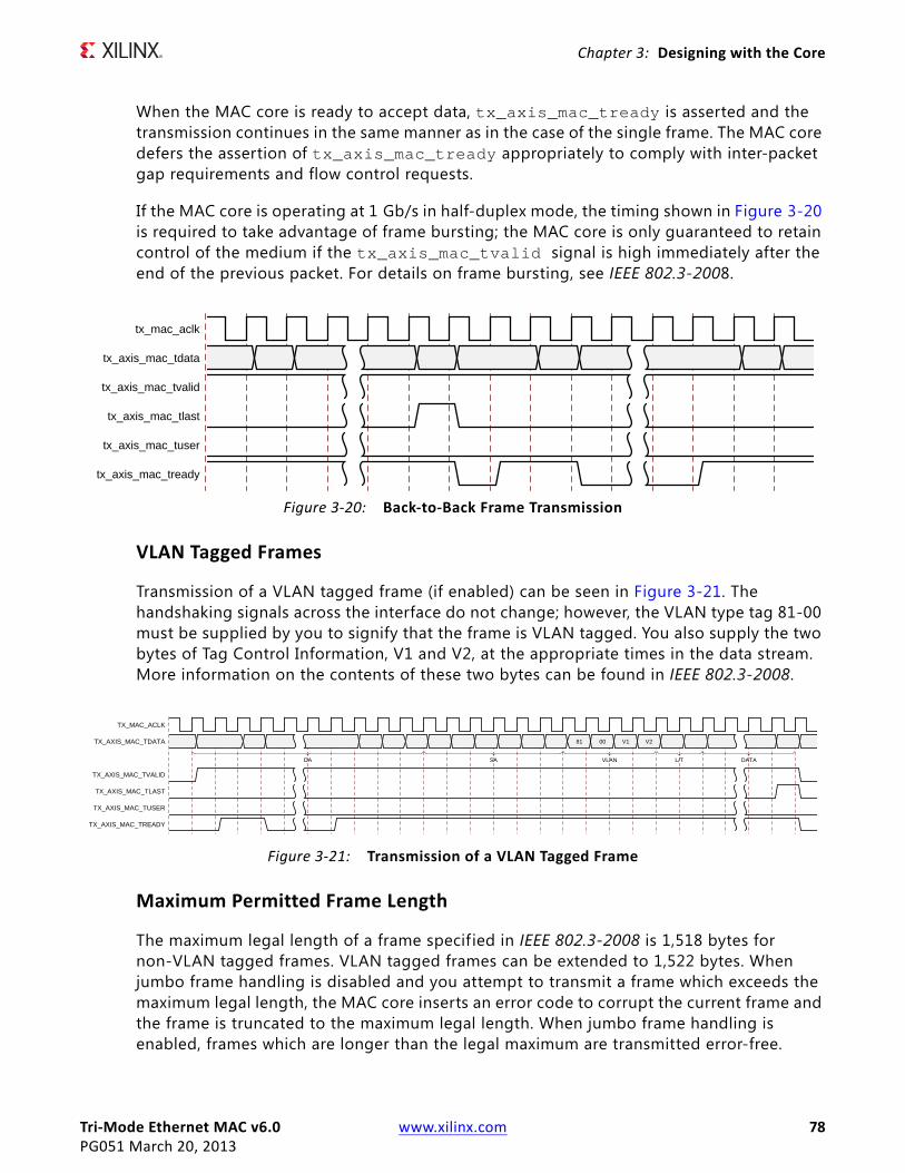
Tri-Mode Ethernet MAC v6.0 www.xilinx.com 78PG051 March 20, 2013
Chapter 3: Designing with the Core
When the MAC core is ready to accept data, tx_axis_mac_tready is asserted and the transmission continues in the same manner as in the case of the single frame. The MAC core defers the assertion of tx_axis_mac_tready appropriately to comply with inter-packet gap requirements and flow control requests.
If the MAC core is operating at 1 Gb/s in half-duplex mode, the timing shown in Figure 3-20 is required to take advantage of frame bursting; the MAC core is only guaranteed to retain control of the medium if the tx_axis_mac_tvalid signal is high immediately after the end of the previous packet. For details on frame bursting, see IEEE 802.3-2008.
VLAN Tagged Frames
Transmission of a VLAN tagged frame (if enabled) can be seen in Figure 3-21. The handshaking signals across the interface do not change; however, the VLAN type tag 81-00 must be supplied by you to signify that the frame is VLAN tagged. You also supply the two bytes of Tag Control Information, V1 and V2, at the appropriate times in the data stream. More information on the contents of these two bytes can be found in IEEE 802.3-2008.
Maximum Permitted Frame Length
The maximum legal length of a frame specified in IEEE 802.3-2008 is 1,518 bytes for non-VLAN tagged frames. VLAN tagged frames can be extended to 1,522 bytes. When jumbo frame handling is disabled and you attempt to transmit a frame which exceeds the maximum legal length, the MAC core inserts an error code to corrupt the current frame and the frame is truncated to the maximum legal length. When jumbo frame handling is enabled, frames which are longer than the legal maximum are transmitted error-free.
X-Ref Target - Figure 3-20
Figure 3-20: Back-to-Back Frame Transmission
tx_mac_aclk
tx_axis_mac_tdata
tx_axis_mac_tvalid
tx_axis_mac_tlast
tx_axis_mac_tuser
tx_axis_mac_tready
X-Ref Target - Figure 3-21
Figure 3-21: Transmission of a VLAN Tagged Frame
TX_MAC_ACLK
TX_AXIS_MAC_TDATA
TX_AXIS_MAC_TVALID
TX_AXIS_MAC_TLAST
TX_AXIS_MAC_TUSER
TX_AXIS_MAC_TREADY
81 00 V1 V2
DA SA VLAN L/T DATA

Tri-Mode Ethernet MAC v6.0 www.xilinx.com 79PG051 March 20, 2013
Chapter 3: Designing with the Core
It is also possible to specify a different maximum frame size. If this is enabled and the frame exceeds the configured value then the frame is corrupted. In this case VLAN frames are not treated separately. If jumbo frame handling is enabled, that takes precedence and the configured value is ignored.
Frame Collisions – Half-Duplex Operation Only
In half-duplex Ethernet operation, collisions occur on the medium as a matter of course; this is how the arbitration algorithm is fulfilled. In the case of a collision, the MAC core signals to you that data might need to be resupplied as follows.
• If there is a collision, the tx_collision signal is set to 1 by the MAC core. If a frame is in progress, you must abort the transfer asserting tx_axis_mac_tlast and tx_axis_mac_tuser.
• If the tx_retransmit signal is 1 in the same cycle that the tx_collision signal is 1, you must then resubmit the previous frame to the MAC core for retransmission; tx_axis_mac_tvalid must be asserted to the MAC core within six cycles of the tx_retransmit signal: if tx_axis_mac_tvalid is asserted later than this, the MAC assumes that the frame is not retransmitted and the number of retransmission attempts counter within the MAC is reset. This case is illustrated in Figure 3-22.
If any frame presented to the user interface is shorter than the collision window (slot time) as defined in IEEE Std 802.3-2008, a retransmission request can occur after the end of the frame as observed on the user interface. Therefore, the user logic (which might have queued a subsequent frame for transmission) might then have to rewind back to the previous frame. In this case the current frame has to be aborted by asserting tx_axis_mac_tlast in conjunction with tx_axis_mac_tuser and the previous frame data should be re-supplied on the tx_axis_mac_tdata[7:0] port within the same six cycles illustrated in Figure 3-22.
For reference only: the collision window (slot time) is 64 validated clock cycles when operating at 10 Mb/s and 100 Mb/s speeds (corresponding to 64-bytes of frame data), and 512 clock cycles when operating at 1 Gb/s speed (corresponding to 512-bytes of frame data).
• If the tx_retransmit signal is 0 in the same cycle that the tx_collision signal is 1, the number of retries for this frame has exceeded the Ethernet specification or the collision has been classed as late, and the frame should be dropped by you. You can then make any new frame available to the MAC for transmission without timing restriction. This case is illustrated in Figure 3-23.

Tri-Mode Ethernet MAC v6.0 www.xilinx.com 80PG051 March 20, 2013
Chapter 3: Designing with the Core
Interframe Gap Adjustment – Full-Duplex Mode Only
A configuration bit in the transmitter control register allows you to control the length of the interframe gap transmitted by the MAC on the physical interface. If this function is selected, the MAC exerts back pressure on the user interface to delay the transmission of the next frame until the requested number of idle cycles has elapsed. The number of idle cycles is controlled by the value on the tx_ifg_delay port seen at the start of frame transmission on the user interface. Figure 3-24 shows the MAC operating in this mode.
The minimum interframe gap supported is dependent upon the support of half-duplex operation. If half-duplex is supported, the minimum IFG possible is eight bytes of transmit data. If the MAC only supports full-duplex operation then this reduces the minimum possible IFG to four bytes of transmit data.
In both cases the interframe gap used when the Interframe Gap Adjust Enable bit is set to 0 is the minimum value as specified in the IEEE 802.3-2008 standard. This corresponds to 12 bytes of transmit data on the GMMI/MII interface. The value on the tx_ifg_delay port must be equal to or larger than four or eight to have an effect as described previously.
X-Ref Target - Figure 3-22
Figure 3-22: Collision Handling – Frame Retransmission Required
X-Ref Target - Figure 3-23
Figure 3-23: Collision Handling – No Frame Retransmission Required
tx_mac_aclk
tx_axis_mac_tdata
tx_axis_mac_tvalid
tx_axis_mac_tlast
tx_axis_mac_tuser
tx_axis_mac_tready
tx_collision
tx_retransmit

Tri-Mode Ethernet MAC v6.0 www.xilinx.com 81PG051 March 20, 2013
Chapter 3: Designing with the Core
Transmitter Statistics Vector
The statistics for the frame transmitted are contained within the tx_statistics_vector output. The bit f ield definition for the Vector is defined in Table 3-3. All bit f ields, with the exception of BYTE_VALID are valid only when the tx_statistics_valid is asserted, as illustrated in Figure 3-25. BYTE_VALID is signif icant on every transmitter cycle that clock enable is high. tx_statistics_vector bits 28 down to 20 inclusive are for half-duplex only and are set to logic 0 when operating in full-duplex mode.
X-Ref Target - Figure 3-24
Figure 3-24: Interframe Gap Adjustment
tx_mac_aclk
tx_axis_mac_tdata
tx_axis_mac_tvalid
tx_axis_mac_tlast
tx_axis_mac_tready
tx_ifg_delay NO IFG ADJUST VALUE NEW IFG ADJUST VALUE
DA DA.
minimum IFG inserted tx_axis_mac_tready held off to allow requested number of idles between frames
X-Ref Target - Figure 3-25
Figure 3-25: Transmitter Statistics Vector Timing
tx_statistics_valid
tx_statistics_vector[31:0]
Table 3-3: Bit Definition for the Transmitter Statistics Vector
emacclienttxstats Name Description
31 PAUSE_FRAME_TRANSMITTED Asserted if the previous frame was a pause frame that the MAC itself initiated in response to a pause_req assertion.
30 BYTE_VALID Asserted if a MAC frame byte (DA to FCS inclusive) is in the process of being transmitted. This is valid on every clock cycle.Do not use this as an enable signal to indicate that data is present on (R)(G)MII_TXD.
29 Reserved Returns logic 0.
28:25 TX_ATTEMPTS[3:0] The number of attempts that have been made to transmit the previous frame. This is a 4-bit number: 0 should be interpreted as 1 attempt; 1 as 2 attempts, up until 15 as 16 attempts.
24 Reserved Returns logic 0.
23 EXCESSIVE_COLLISION Asserted if a collision has been detected on each of the last 16 attempts to transmit the previous frame.
22 LATE_COLLISION Asserted if a late collision occurred during frame transmission.

Tri-Mode Ethernet MAC v6.0 www.xilinx.com 82PG051 March 20, 2013
Chapter 3: Designing with the Core
Flow ControlThis section describes the operation of the flow control logic of the TEMAC solution. The flow control block is designed to clause 31 of the IEEE 802.3-2008 [Ref 8] standard. In full duplex mode the MAC can be configured to transmit pause requests and to act on their reception; these modes of operation can be independently enabled or disabled.
21 EXCESSIVE_DEFERRAL Asserted if the previous frame was deferred for an excessive amount of time as defined by the constant “maxDeferTime” in IEEE 802.3-2008.
20 TX_DEFERRED Asserted if transmission of the frame was deferred.
19 VLAN_FRAME Asserted if the previous frame contained a VLAN identif ier in the length/type f ield when transmitter VLAN operation is enabled.
18:5 FRAME_LENGTH_COUNT The length of the previous frame in number of bytes. The count stays at 16368 for any jumbo frames larger than this value.
4 CONTROL_FRAME Asserted if the previous frame had the special MAC Control Type code 88-08 in the length/type f ield.
3 UNDERRUN_FRAME Asserted if the previous frame contained an underrun error.
2 MULTICAST_FRAME Asserted if the previous frame contained a multicast address in the destination address field.
1 BROADCAST_FRAME Asserted if the previous frame contained a broadcast address in the destination address field.
0 SUCCESSFUL_FRAME Asserted if the previous frame was transmitted without error.
Table 3-3: Bit Definition for the Transmitter Statistics Vector (Cont’d)
emacclienttxstats Name Description

Tri-Mode Ethernet MAC v6.0 www.xilinx.com 83PG051 March 20, 2013
Chapter 3: Designing with the Core
Overview of Flow Control
Flow Control RequirementX-Ref Target - Figure 3-26
Figure 3-26 illustrates the requirement for Flow Control at 1 Gb/s. The MAC on the right side of the f igure has a reference clock slightly faster than the nominal 125 MHz. The MAC on the left side of the figure has a reference clock slightly slower than the nominal 125 MHz. This results in the MAC on the left side of the f igure not being able to match the full line rate of the MAC on the right side (due to clock tolerances). The MAC at the left is illustrated as performing a loopback implementation, which results in the FIFO filling up over time. Without Flow Control, this FIFO eventually f ills and overflows, resulting in the corruption or loss of Ethernet frames. Flow Control is one solution to this issue.
Flow Control Basics
A MAC can transmit a Pause Control frame to request that its link partner cease transmission for a specif ic period of time. For example, the left MAC in Figure 3-26 can initiate a pause request when its user FIFO (illustrated) reaches a nearly full state.
A MAC should respond to received Pause Control frames by ceasing transmission of frames for the period of time defined in the received pause control frame. For example, the right MAC of Figure 3-26 can cease transmission after receiving the Pause Control frame transmitted by the left MAC. In a well designed system, the right MAC ceases transmission
Figure 3-26: Requirement for Flow Control
MAC
FIFO
User Logic
Tx
Rx
MAC
Tx
Rx
125 MHz -100ppm
125 MHz +100ppm
App
licat
ion

Tri-Mode Ethernet MAC v6.0 www.xilinx.com 84PG051 March 20, 2013
Chapter 3: Designing with the Core
before the user FIFO of the left MAC overflows to provide time to empty the FIFO to a safe level before resuming normal operation. This practice safeguards the system against FIFO overflow conditions and frame loss.
Pause Control Frames
Control frames are a special type of Ethernet frame defined in clause 31 of the IEEE 802.3 standard. Control frames are identif ied from other frame types by a defined value placed into the length/type f ield (the MAC Control Type code). Figure 3-27 illustrates control frame format.
A Pause Control frame is a special type of Control frame, identif ied by a defined value placed into the MAC Control opcode field.
Note: MAC Control OPCODES other than for Pause (Flow Control) frames have also been defined for Ethernet Passive Optical Networks.
The MAC Control Parameter f ield of the Pause Control frame contains a 16-bit f ield which contains a binary value directly relating to the duration of the pause. This defines the number of pause_quantum (512-bit times of the particular implementation). At 1 Gb/s, a single pause_quantum corresponds to 512 ns. At 100 Mb/s, a single pause_quantum corresponds to 5,120 ns, and at 10 Mb/s, a single pause_quantum corresponds to 51,200 ns.
X-Ref Target - Figure 3-27
Figure 3-27: MAC Control Frame Format
DESTINATIONADDRESS
SOURCEADDRESS
LENGTH/TYPE
MAC CONTROLOPCODE
MAC CONTROLPARAMETERS
RESERVED(transmitted as zeroes)
6 OCTETS
6 OCTETS
2 OCTETS
2 OCTETS
(minFrameSize - 160) /8OCTETS
OCTETS WITIHINFRAME TRANSMITTEDTOP-TO-BOTTOM
LSB MSB
BITS WITHINFRAME TRANSMITTED
LEFT-TO-RIGHT

Tri-Mode Ethernet MAC v6.0 www.xilinx.com 85PG051 March 20, 2013
Chapter 3: Designing with the Core
Flow Control Operation of the TEMAC
Transmitting a Pause Control Frame
Core-Initiated Pause Request
If the core is configured to support transmit flow control, you can initiate a flow control frame by asserting pause_req while the pause value is on the pause_val bus. Figure 3-28 illustrates this timing. Pause request signals are synchronous to the gtx_clk clock.
This action causes the core to construct and transmit a Pause Control frame on the link with the following MAC Control frame parameters (see Figure 3-27):
• The destination address used is an IEEE 802.3 globally assigned multicast address (which any Flow Control capable MAC responds to).
• The source address used is the configurable Pause Frame MAC Address.
• The value sampled from the pause_val[15:0] port at the time of the pause_req assertion is encoded into the MAC Control Parameter f ield to select the duration of the pause (in units of pause_quantum).
If the transmitter is currently inactive at the time of the pause request, this Pause Control frame is transmitted immediately. If the transmitter is currently busy, the current frame being transmitted is allowed to complete; the Pause Control frame then follows in preference to any pending user supplied frame. A Pause Control frame initiated by this method is transmitted even if the transmitter itself has ceased transmission in response to receiving an inbound pause request.
Note: Only a single pause control frame request is stored by the transmitter. If the pause_req signal is asserted numerous times in a short time period (before the control pause frame transmission has had a chance to begin), only a single pause control frame is transmitted. The pause_val[15:0] value used is the most recent value sampled.
User-Initiated Pause Request
For maximum flexibility, flow control logic can be disabled in the core and alternatively implemented in the user logic connected to the core. Any type of Control frame can be transmitted through the core through the TX AXI4-Stream interface using the same transmission procedure as a standard Ethernet frame (see Transmitting Outbound Frames).
X-Ref Target - Figure 3-28
Figure 3-28: Pause Request Timing
pause_req
pause_val
Tri-Mode Ethernet MAC v6.0 www.xilinx.com 86PG051 March 20, 2013
Chapter 3: Designing with the Core
Receiving a Pause Control Frame
Core-Initiated Response to a Pause Request
An error-free Control frame is a received frame matching the format of Figure 3-27. It must pass all standard receiver frame checks (for example,. FCS f ield checking); in addition, the control frame received must be exactly 64 bytes in length (from destination address through to the FCS f ield inclusive). This is minimum legal Ethernet MAC frame size and the defined size for control frames.
Any Control frame received that does not conform to these checks contains an error, and it is passed to the RX AXI4-Stream as an errored packet (rx_axis_mac_tuser asserted)
Pause Frame Reception Disabled
When pause control reception is disabled, an error-free control frame is received through the RX AXI4-Stream interface. In this way, the frame is passed to the user logic for interpretation (see User-Initiated Response to a Pause Request, page 87).
Pause Frame Reception Enabled
When pause control reception is enabled and an error-free frame is received by the MAC core, the following frame decoding functions are performed:
1. The destination address field is matched against the IEEE 802.3 globally assigned control multicast address (01-80-C2-00-00-01) or the configurable Pause Frame MAC Address.
2. The length/type field is matched against the MAC Control Type code.
3. If the second match is TRUE, the OPCODE field contents are matched against the Ethernet MAC control OPCODE for pause frames.
If all the previously listed checks are TRUE, and the frame is of minimum legal size OR larger and control frame length checking is disabled, the 16-bit binary value in the MAC control parameters f ield of the control frame is then used to inhibit transmitter operation for the required number of pause_quantum. This inhibit is implemented by delaying the assertion of tx_axis_mac_tready at the TX AXI4-Stream interface until the requested pause duration has expired. Because the received pause frame has been acted upon, it is passed to the RX AXI4-Stream interface as an errored packet to indicate to you that it can now be dropped.
If the second match is TRUE and the frame is not exactly 64 bytes in length (when control frame length checking is enabled), the reception of any frame is considered to be an invalid control frame. This frame is ignored by the flow control logic and passed to the RX AXI4-Stream interface as an errored frame. In this case the frame is errored even if flow control is not enabled.
Tri-Mode Ethernet MAC v6.0 www.xilinx.com 87PG051 March 20, 2013
Chapter 3: Designing with the Core
If any of the previously listed checks are FALSE, the frame is ignored by the Flow Control logic and passed up to the user logic for interpretation by marking it as a good frame. It is then the responsibility of the MAC user logic to decode, act on (if required) and drop this control frame.
Note: Any frame in which the length/type f ield contains the MAC Control Type in the length/type f ield should be dropped by the receiver user logic. All Control frames are indicated by rx_statistics_vector bit 19 (see Receiver Statistics Vector).
User-Initiated Response to a Pause Request
For maximum flexibility, flow control logic can be disabled in the core and alternatively implemented in the user logic connected to the core. Any type of error-free Control frame is then passed through the core without error. In this way, the frame is passed to you for interpretation. It is your responsibility to drop this control frame and to act on it by ceasing transmission through the core, if applicable.
Flow Control Implementation ExampleThis explanation is intended to describe a simple (but crude) example of a Flow Control implementation to introduce the concept.
Consider the system illustrated in Figure 3-26. To summarize the example, the MAC on the left-hand side of the figure cannot match the full line rate of the right-hand MAC due to clock tolerances. Over time, the FIFO illustrated f ills and overflows. The aim is to implement a Flow Control method which, over a long time period, reduces the full line rate of the right-hand MAC to average that of the lesser full line rate capability of the left-hand MAC.
Method
1. Choose a FIFO nearly full to occupancy threshold (7/8 occupancy is used in this description). When the occupancy of the FIFO exceeds this occupancy, initiate a single pause control frame with 0xFFFF used as the pause_quantum duration (0xFFFF is placed on pause_val[15:0]). This is the maximum pause duration. This causes the right-hand MAC to cease transmission and the FIFO of the left-hand MAC starts to empty.
2. Choose a second FIFO occupancy threshold (3/4 is used in this description). When the occupancy of the FIFO falls below this occupancy, initiate a second pause control frame with 0x0000 used as the pause_quantum duration (0x0000 is placed on pause_val[15:0]). This indicates a zero pause duration, and upon receiving this pause control frame, the right-hand MAC immediately resumes transmission (it does not wait for the original requested pause duration to expire). This pause control frame can therefore be considered a “pause cancel” command.

Tri-Mode Ethernet MAC v6.0 www.xilinx.com 88PG051 March 20, 2013
Chapter 3: Designing with the Core
Operation
Figure 3-29 illustrates the FIFO occupancy over time.
The following text describes the sequence of flow control operation in this example.
1. The average FIFO occupancy of the left-hand MAC gradually increases over time due to the clock tolerances. At point A, the occupancy has reached the threshold of 7/8 occupancy. This triggers the maximum duration pause control frame request.
2. Upon receiving the pause control frame, the right-hand MAC ceases transmission.
3. After the right-hand MAC ceases transmission, the occupancy of the FIFO attached to the left-hand MAC rapidly empties. The occupancy falls to the second threshold of 3/4 occupancy at point B. This triggers the zero duration pause control frame request (the pause cancel command).
4. Upon receiving this second pause control frame, the right-hand MAC resumes transmission.
5. Normal operation resumes and the FIFO occupancy again gradually increases over time. At point C, this cycle of Flow Control repeats.
X-Ref Target - Figure 3-29
Figure 3-29: Flow Control Implementation Triggered from FIFO Occupancytime
FIF
O o
ccup
ancy
3/4
7/8
5/8
1/2
Full
A
B
C

Tri-Mode Ethernet MAC v6.0 www.xilinx.com 89PG051 March 20, 2013
Chapter 3: Designing with the Core
Statistics CountersThe Statistics counters (Table 2-22), which are only available when the management interface is enabled, can be defined to be either 32 or 64 bits wide, with 64 bits being the default. When defined as 64 bits wide the counter values are captured across two registers. In all cases a read of the lower 32-bit value causes the upper 32 bits to be sampled. A subsequent read of the upper 32-bit location returns this sampled value. If an upper location for a different counter is read, the access returns an error condition to indicate that the returned data value is incorrect.
Note: All statistics counters are Read Only. A write to any location is ignored and returns an error.
The Statistics counters can optionally be reset upon a global reset, with this being enabled using the GUI. They do not reset upon a read and wrap around when the maximum count value is reached. It is your responsibility to ensure the counters are read frequently enough to guarantee a wraparound is not missed.
The TEMAC core always outputs RX and TX statistics vectors and, when the statistics counters are present, these are decoded in the Vector Decode block, provided in the Block level, which in turn, provides the “increment vector” bus to the TEMAC core. It is the contents of the increment vector which dictate which statistic counters are to increment.
The Vector Decode block is provided in plain text HDL, allowing you the ability to customize the statistic counters provided. The following sections therefore describe the operation of the statistic counter logic and its interfaces in detail to allow for a custom implementation. To use the default statistic counters as provided, these sections can be skipped.
Increment Interface Overview
The Increment Interface has two main logical sections:
• A low-frequency increment component controlled by the increment vector input. This accommodates the majority of the statistical counters, which only increment at (or less frequently than) a standard minimum Ethernet frame period. These are decoded in the Vector Decode block and therefore can be edited by you if desired though this is not recommended for the pre-defined counters.
• A high-frequency increment component. These are generated internally to the Ethernet MAC core level and as such cannot be edited or monitored by you. These are used to accommodate those counters which can increment on every cycle and these are captured in counters 0-3.
Low-Frequency Statistical Counters
The increment_vector[4:43] is an input bus signal which provides the predefined counters as described in Table 2-22 and three user defined counters. This accommodates the vast

Tri-Mode Ethernet MAC v6.0 www.xilinx.com 90PG051 March 20, 2013
Chapter 3: Designing with the Core
majority of the statistical counters which only increment at (or less frequently than) a minimum Ethernet frame period.
Figure 3-30 illustrates the increment_vector bus provided by the vector decode block. There is an increment bit for each counter from counter 4 upwards. A toggle on a particular increment bit causes the corresponding counter to increment. The mapping of the increment vector bits to the various register mapped counter is shown in Table 2-22.
The increment_vector is input to the core and edge detection circuitry (toggle detection) is placed on each bit. The toggle detection circuitry is synchronous to stats_ref_clk . Within the core, the current counter values are stored in distributed memory. The Statistics core accesses each of the counters within this memory in a round robin fashion and if an increment has been requested since the last access the relative value is incremented prior to being written back to memory.
Bandwidth Requirements
The frequency of stats_ref_clk is flexible but depends upon both the number of counters and the maximum frequency supported by the MAC. The low-frequency increment vectors can update at a maximum rate of once per minimum sized Ethernet frame. This translates to 584 ns when running at 1 Gb/s (64 bytes of minimum Ethernet frame size, plus 1-byte of minimum received preamble, plus eight bytes of minimum received interframe gap, at a byte rate of 1-byte per 8 ns).
With stats_ref_clk set to 125 MHz, 36 statistical counters can be safely updated between successive Ethernet frames (584 ns divided by the 8 ns clock period of stats_ref_clk , divided by 2 because a counter update requires two accesses). As this is less than the provided 44 counters extra decode logic is included to take advantage of the frame size counters one-hot status (that is, only one of the seven RX and one of the seven TX frame size counters can update on a per packet basis. The round-robin function which controls which counter is being accessed only accesses the required frame size counter and skips the other 5. This means the 44 counters supported only require 32 counter accesses. However, this does mean that the stats_ref_clk should be at least as fast as the clock
X-Ref Target - Figure 3-30
Figure 3-30: Increment Vector Timing Diagram
increment_vector[17]
Do not toggle more frequently thanthe low frequency increment period
Will cause an incrementto counter number 17
Will cause an incrementto counter number 17

Tri-Mode Ethernet MAC v6.0 www.xilinx.com 91PG051 March 20, 2013
Chapter 3: Designing with the Core
used for the maximum rate supported by the MAC (125 MHz at 1 Gb/s or 12.5 MHz at 10/100 Mb/s).
Frame FilterThe MAC can be configured with an optional frame filter. This is available irrespective of the use of the management interface but has much reduced functionality if no management interface is present; this use model is described in Configuration Vector.
The frame filter performs two functions:
• Checking any received packet matches of one of the predefined Destination Address values: Pause Address, Broadcast Address, User Defined Unicast Address and the special multicast Pause Address.
• Comparing the f irst 64 bytes of a received packet against a user defined pattern.
In the case of the Destination Address comparisons, the results are used in other blocks within the MAC, such as flow control and in the generation of statistics vectors.
The other function of the frame filter is much more flexible and allows you to specify any match pattern within the f irst 64 bytes whilst ignoring any other byte or bit values. This is extremely flexible as it enables packets to be f iltered based on almost any header field or combination of header f ields. Each frame filter contains two 512-bit registers (64 bytes):
• Frame Filter Value register. This pattern is compared to the f irst 512 bits received in a frame with bit 0 being the f irst bit within a frame to be received.
• Frame Filter Mask Value register. Each bit within this register refers to the same bit number within the Frame Filter Value register. when a bit in the Mask Value Register is set to
° logic 1, The same bit number within the Frame Filter Value register is compared with the respective bit in the received frame and must match if the overall frame filter is to obtain a match.
° logic 0, the same bit number within the Frame Filter Value register is not compared. This effectively turns the respective bit in the Frame Filter Value register into a don’t care bit: the overall frame filter is capable of obtaining a match even if this bit does not match.
This is described in more detail in Using the Frame Filter.
You can specify up to eight frame filters in the Ethernet MAC core level, with an additional three being used if the AVB Endpoint is present. Each is accessed through address mapped registers. However, because each f ilter requires 32 registers to access the pattern and mask values there is a control register which specifies which of the f ilters is being accessed with

Tri-Mode Ethernet MAC v6.0 www.xilinx.com 92PG051 March 20, 2013
Chapter 3: Designing with the Core
all f ilters being accessed through the same register set. When 1 or more frame filters are specified the rx_axis_filter_tuser output is available from the Ethernet MAC core level. This is sized depending upon the number of f ilters selected and provides a direct pass/fail indication on a per f ilter basis, this does not include a AVB specif ic f ilters. See Using the Frame Filter for more detail.
Table 2-39 shows the frame filter configuration registers.
Using the Frame FilterThe Configurable frame filters can be used to perform simple Destination Address filtering, Multicast Group matching, Source Address matching and VLAN field matching. The use of the Mask register enables any field or combination of f ields in the f irst 64 bytes to be isolated and matched. The Frame Filter Control register, shown in Table 2-42, allows you to enable or disable the frame filter by setting the promiscuous Mode bit which has the following functionality:
• When enabled, all good frames are marked as good.
• When disabled, only frames which match one or more of the pre-defined Destination Address filters or the configurable frame filters are marked good.
When more than one frame filter is generated it is necessary to write to the Frame Filter Control register to specify which frame filter is being accessed prior to writing to any of the f ilter specif ic registers. It is then possible to enable each frame filter individually. While a particular f ilter is disabled it does not match any packets. It is recommended that frame filters are disabled prior to updating the match pattern to avoid unexpected packets being accepted.
By default all non-AVB frame filters are configured with all 1s in the bottom 48 bits in both the Frame Filter Value registers and the Frame Filter Mask Value registers; this results in a broadcast frame match, which has no effect as they are already accepted by the pre-defined Destination Address filters. After the frame filter value and mask value have been updated to the desired values the f ilter should be enabled.
In Figure 3-31 the reception of an error free frame which matches against f ilter 0 is shown. In this example, the rx_axi_filter_tuser is treated as a “bad frame” indicator and is asserted when you want the frame to be dropped (that is, when the appropriate filter did not match against the frame). When one or more f ilters are generated, the rx_axis_filter_tuser bus is generated with one extra bit; for example if four filters are selected, rx_axis_filter_tuser would be a 5-bit bus. This extra bit (always the upper bit) is used to provide the “else” case. It is asserted if any of the user-defined f ilters match a frame to indicate that the frame should be dropped.
If using the rx_axis_filter_tuser outputs this would mean the frame is being serviced by a dedicated output and should therefore be dropped by the else output. This is shown in Figure 3-32 where a good frame has matched against a pre-defined Destination Address f ilter but failed to match any of the configurable f ilters.

Tri-Mode Ethernet MAC v6.0 www.xilinx.com 93PG051 March 20, 2013
Chapter 3: Designing with the Core
This extra bit allows the rx_axis_filter_tuser bus to be used to directly drive FIFOs for particular f ilter matches, such as VLAN priority. When the frame filter is configured in Promiscuous Mode the rx_axis_filter_tuser bits continue to operate as normal.
Frame Filter Example ApplicationThis section describes the usage of the frame filter to implement VLAN priority based f iltering.
X-Ref Target - Figure 3-31
Figure 3-31: Received Frame with a Match on Filter 0
rx_mac_aclk
rx_axis_mac_tdata
rx_axis_mac_tvalid
rx_axis_mac_tlast
rx_axis_mac_tuser
rx_axis_filter_tuser[0]
rx_axis_filter_tuser[x]
DA SA L/T DATA
X-Ref Target - Figure 3-32
Figure 3-32: Received Frame with No Match on Configurable Frame Filters
rx_mac_aclk
rx_axis_mac_tdata
rx_axis_mac_tvalid
rx_axis_mac_tlast
rx_axis_mac_tuser
rx_axis_filter_tuser[0]
rx_axis_filter_tuser[x]
DA SA L/T DATA

Tri-Mode Ethernet MAC v6.0 www.xilinx.com 94PG051 March 20, 2013
Chapter 3: Designing with the Core
In Figure 3-33, the MAC is shown connected to priority FIFOs. In this case frame filter 0 is set up to match on the VLAN Type and the VLAN Priority f ield with a value of 7. In a standard VLAN Ethernet frame, the VLAN type value of 0x8100 is found in bytes 13-14, with the priority f ield being the upper three bits of byte 15. This required these register settings:
• Frame Filter Value bytes 15-12 set to 0xE0008100
• Frame Filter Mask Value bytes 15-12 set to 0xE0FFFF00
• All other Frame Filter Mask Value bytes set to 0x0
In this case the FIFO, which is using rx_axis_filter_tuser[0], is only passing good VLAN frames which have a priority f ield set to 7. The default FIFO, which is using rx_axis_filter_tuser[4](that is, the “else” bit of the signal), only accepts good frames which are either not VLAN frames or have a priority f ield with a value other than 7. This is illustrated in Figure 3-34.
X-Ref Target - Figure 3-33
Figure 3-33: Priority FIFO Connections
X-Ref Target - Figure 3-34
Figure 3-34: Filtering of VLAN Frames with VLAN Priority of 7
rx_mac_aclk
rx_axis_mac_tdata
rx_axis_mac_tvalid
rx_axis_mac_tlast
rx_axis_mac_tuser
Frame Filter Value
Frame Filter Mask
X X X X X X X X X X X X 81 00 E0 X X
0 0 0 0 0 0 0 0 0 0 0 0 FF FF E0 0 0
DA SA VLAN L/T DATA
Don’t Care Check Don’t Care

Tri-Mode Ethernet MAC v6.0 www.xilinx.com 95PG051 March 20, 2013
Chapter 3: Designing with the Core
Using the AVB Specific Frame FiltersThis section is only applicable if the TEMAC solution is implemented with the optional Ethernet AVB Endpoint functionality.
The three AVB frame filters are initialized to identify PTP frames and AV frames of both priorities. These initial values can be adjusted to change the VLAN field values used by the software drivers as required.
The Frame Filter Control register (Table 2-42) allows you to access each of the AVB frame filters by setting Bit[8], AVB Select. When set, Bits[1:0] are used to specify the required AVB frame filter with the value of 3 being ignored. See AVB Specif ic Frame Filters for the register definitions of the PTP Frame filter.
SR Classes A and B Frame Filters
Two frame filters are provided to identify frames belonging to either SR Class A or SR Class B. The SR Class A frame filter can be accessed by setting Filter Index to 1 in the Frame Filter Control register (see Table 2-42) and the SR Class B frame filter can be accessed by setting Filter Index to 2.
The output of the two filters is combined so that a match against either filter allows AV traffic to pass. If only one SR Class is supported then either disable the undesired f ilter or set both f ilters to the same value.
The default behavior of the SR Class frame filters is to match both the default VLAN PCP and VLAN ID values for that SR Class, as follows:
SR Class A:
Type = 0x0081 (VLAN)
Type_info = 0x0260 (VLAN PCP = 3 VLAN ID = 2)
SR Class B:
Type = 0x0081 (VLAN)
Type_info = 0x0240 (VLAN PCP = 2VLAN ID = 2)
This translates to the register settings in Tables 2-48 to 2-51.
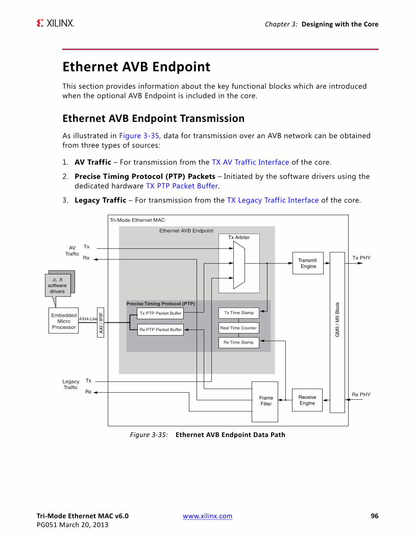
Tri-Mode Ethernet MAC v6.0 www.xilinx.com 96PG051 March 20, 2013
Chapter 3: Designing with the Core
Ethernet AVB EndpointThis section provides information about the key functional blocks which are introduced when the optional AVB Endpoint is included in the core.
Ethernet AVB Endpoint TransmissionAs illustrated in Figure 3-35, data for transmission over an AVB network can be obtained from three types of sources:
1. AV Traffic – For transmission from the TX AV Traff ic Interface of the core.
2. Precise Timing Protocol (PTP) Packets – Initiated by the software drivers using the dedicated hardware TX PTP Packet Buffer.
3. Legacy Traffic – For transmission from the TX Legacy Traff ic Interface of the core.X-Ref Target - Figure 3-35
Figure 3-35: Ethernet AVB Endpoint Data Path

Tri-Mode Ethernet MAC v6.0 www.xilinx.com 97PG051 March 20, 2013
Chapter 3: Designing with the Core
TX Legacy Traffic Interface
The legacy traff ic interface is maintained for best effort Ethernet data: Ethernet as it is known today (for example, a PC surf ing the internet). The signals forming the TX Legacy Traffic interface are defined in Table 2-5. The timing of this interface is as described in Transmitting Outbound Frames, with the interface functionality limited to full-duplex, no jumbo support, VLAN frames enabled and flow control disabled.
TX AV Traffic Interface
The AV traff ic interface is intended for the Quality of Service audio/video data. The Ethernet AVB Endpoint gives priority to the AV traff ic interface over the legacy traff ic interface, as dictated by IEEE 802.1Q 75% bandwidth restrictions. The signals forming the TX AV Traff ic interface are defined in Table 2-7. The timing of this interface is exactly the same as for the TX Legacy Traff ic with the only difference being how the tvalid signal is handled between frames.
In Figure 3-36, following the end of frame transmission, the tx_axis_av_tvalid signal is held high, which indicates to the Credit Based Traffic Shaping Algorithm that another AV frame is queued. Unless the configurable bandwidth restrictions have been exceeded, this parks the Credit Based Traff ic Shaping Algorithm onto the AV traff ic queue and the following frame can immediately be taken. However, if no further AV traff ic frames are queued, the tx_axis_av_tvalid signal should be set to low immediately following the end of frame transmission. This then allows the Credit Based Traffic Shaping Algorithm to schedule legacy traffic transmission (if any legacy frames are queued).
If, following the end of frame reception, the bandwidth allocation for AV traff ic has been exceeded, the Credit Based Traffic Shaping Algorithm switches to service the legacy traffic regardless of the state of the tx_axis_av_tvalid signal.
Transmitter AXI4-Stream AV Specifics
One of the key functions of the Ethernet AVB Endpoint is the configurable bandwidth allocation for the AV user data. Because this bandwidth is managed over time this is done using credits which are gained when non-AV data is sent and lost when AV data is sent, with a positive or zero balance of credits enabling the AV path. When no data is present at the AV
X-Ref Target - Figure 3-36
Figure 3-36: TX AV Traffic Timing
tx_mac_aclk
tx_axis_av_tdata
tx_axis_av_tvalid
tx_axis_av_tlast
tx_axis_av_tready
tx_axis_av_tuser
Frame 1 Frame 2

Tri-Mode Ethernet MAC v6.0 www.xilinx.com 98PG051 March 20, 2013
Chapter 3: Designing with the Core
input, any credits available are removed thus preventing bursty AV traffic getting an artif icially high bandwidth. The tx_axis_av_tvalid indicates that data is available, but at the end of a frame, if another frame is available, the tx_axis_av_tvalid should remain asserted and the first byte of the new frame should be presented. This is shown in Figure 3-36. If tx_axis_av_tvalid is dropped between frames then any positive credit balance is lost and a negative balance remains, which results in a lower overall bandwidth allowance for the AV path.
TX Arbiter
Overview
As illustrated in Figure 3-35, data for transmission over an AVB network can be obtained from three types of sources.
The transmitter (TX) arbiter selects from these three sources in the following manner.
• If there is AV data available and the programmed AV bandwidth limitation is not exceeded, then the AV packet is transmitted
• otherwise the TX arbiter checks to see if there are any PTP packets to be transmitted
• otherwise if there is an available legacy packet then this is transmitted.
The Ethernet AVB Endpoint uses configuration registers to set up the percentage of available Ethernet bandwidth reserved for AV traff ic. To comply with the IEEE802.1Q specification these should not be configured to exceed 75%. The arbiter then polices this bandwidth restriction for the AV traff ic and ensures that on average, it is never exceeded. Consequently, despite the AV traff ic having a higher priority than the legacy traff ic, there is always remaining bandwidth available to schedule legacy traff ic.
The relevant configuration registers for programming the bandwidth percentage dedicated to AV traff ic are defined in Configuration and Status and are:
• TX Arbiter Send Slope Control Register
• TX Arbiter Idle Slope Control Register
These registers are defaulted to values which dedicate up to 75% of the overall bandwidth to the AV traff ic. This is the maximum legal percentage that is defined in the IEEE802.1 AVB standards.
In many implementations, it might be unnecessary to change these register values. Correct use of the tx_axis_av_tvalid signal, as defined in TX AV Traffic Interface, allows the TX Arbiter to share the bandwidth allocation eff iciently between the AV and Legacy sources (even in the situations where the AV traffic requires less than 75% of the overall bandwidth). However, for the cases that require less than 75% of the overall bandwidth, careful configuration can result in a smoother (less bursty) transmission of the AV traffic, which should prevent frame bunching across the AVB network.
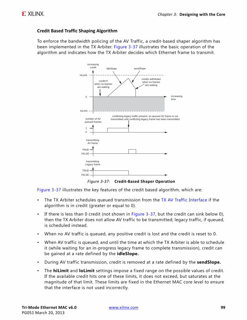
Tri-Mode Ethernet MAC v6.0 www.xilinx.com 99PG051 March 20, 2013
Chapter 3: Designing with the Core
Credit Based Traffic Shaping Algorithm
To enforce the bandwidth policing of the AV Traff ic, a credit-based shaper algorithm has been implemented in the TX Arbiter. Figure 3-37 illustrates the basic operation of the algorithm and indicates how the TX Arbiter decides which Ethernet frame to transmit.
Figure 3-37 illustrates the key features of the credit based algorithm, which are:
• The TX Arbiter schedules queued transmission from the TX AV Traff ic Interface if the algorithm is in credit (greater or equal to 0).
• If there is less than 0 credit (not shown in Figure 3-37, but the credit can sink below 0), then the TX Arbiter does not allow AV traff ic to be transmitted; legacy traff ic, if queued, is scheduled instead.
• When no AV traff ic is queued, any positive credit is lost and the credit is reset to 0.
• When AV traff ic is queued, and until the time at which the TX Arbiter is able to schedule it (while waiting for an in-progress legacy frame to complete transmission), credit can be gained at a rate defined by the idleSlope.
• During AV traff ic transmission, credit is removed at a rate defined by the sendSlope.
• The hiLimit and loLimit settings impose a f ixed range on the possible values of credit. If the available credit hits one of these limits, it does not exceed, but saturates at the magnitude of that limit. These limits are fixed in the Ethernet MAC core level to ensure that the interface is not used incorrectly.
X-Ref Target - Figure 3-37
Figure 3-37: Credit-Based Shaper Operation
hiLimit
loLimit
0 increasingtime
credit=0when no frames
are waiting
idleSlope sendSlope
credits withdrawnwhen no frames
are waiting
increasingcredit
number of AVqueued frames
0
transmittingAV frame
transmittingLegacy frame
TRUE
TRUE
FALSE
FALSE
1
conflicting legacy traffic present, so queued AV frame is nottransmitted until conflicting legacy frame has been transmitted

Tri-Mode Ethernet MAC v6.0 www.xilinx.com 100PG051 March 20, 2013
Chapter 3: Designing with the Core
The overall intention of the two settings idleSlope and sendSlope is to spread out the AV traffic transmission as evenly as possible over time, preventing periods of bursty AV transmission surrounded by idle AV transmission periods. No further background information is provided in this document with regard to the credit-based algorithm. The remainder of this section describes the idleSlope, and sendSlope variables from the perspective of the TX Arbiter.
TX Arbiter Bandwidth Control
The configuration register settings, used for setting the cores local definitions of idleSlope and sendSlope, are described in general, and then from the point of view of a single example which describes the calculations made to set the register default values. This example dedicates up to 75% of the overall bandwidth to be reserved for the AV traffic (leaving at least 25% for the Legacy Traffic).
The calculations described are independent of Ethernet operating speed (no re-calculation is required when changing between Ethernet speeds of 1 Gb/s and 100 Mb/s).
idleSlope
The general equation is:
idleSlopeValue=(AV percentage / 100) x 8192
In this example, dedicating up to 75% of the total bandwidth to the AV traffic:
idleSlopeValue=(75 / 100) x 8192 = 6144
The calculated value for the idleSlopeValue should be written directly to the TX Arbiter Send Slope Control Register. This provides a per-byte increment value when relating this to Legacy Ethernet frame transmission.
sendSlope
The general equation is:
sendSlopeValue=((100 - AV percentage) / 100) x 8192
In this example, dedicating up to 75% of the total bandwidth to the AV traffic, obtain:
sendSlopeValue=((100 - 75) / 100) x 8192 = 2048
The calculated value for the sendSlopeValue should be written directly to the TX Arbiter Idle Slope Control Register. This provides a per-byte decrement value when relating this to AV Ethernet frame transmission.

Tri-Mode Ethernet MAC v6.0 www.xilinx.com 101PG051 March 20, 2013
Chapter 3: Designing with the Core
Ethernet AVB Endpoint ReceptionWhen the AVB Endpoint is present the optional frame filter is always present with three dedicated f ilters for the identif ication of AVB specific frames. As shown in Figure 3-35 received data from an AVB network can be of three types:
• Precise Timing Protocol (PTP) Packets – Routed to the dedicated hardware RX PTP Packet Buffer which can be accessed by the software drivers. PTP packets are identif ied by searching for a specif ic MAC Destination Address and Type f ield.
• AV Traffic – Routed to the RX AV Traff ic Interface of the core. These packets are identif ied by searching for MAC packets containing a MAC VLAN field with one of two possible configurable VLAN PCP and VID combinations.
• Legacy Traffic – Routed to the RX Legacy Traff ic Interface of the core. All packet types which are not identif ied as PTP or AV Traffic are considered legacy traff ic.
RX Legacy Traffic Interface
The signals forming the RX Legacy Traffic Interface are defined in Table 2-8. The timing of this interface is as described in Receiving Inbound Frames, with the interface functionality limited to full-duplex, no jumbo support, VLAN frames enabled and no flow control.
RX AV Traffic Interface
The signals forming the RX AV Traff ic Interface are defined in Table 2-10. The timing of this interface is exactly the same as for the RX Legacy Traffic (there is a one-to-one correspondence between signal names when the axis_mac is exchanged for axis_av).
The RX AV traff ic is identif ied using the dedicated AVB frame filters. These are only present when the AVB Endpoint is include in the TEMAC core and are initialized to match against the default AV VLAN p and VLAN Q values. These are described in more detail in Using the AVB Specif ic Frame Filters.
Real-Time Clock and TimestampingThis chapter considers two of the logical components that are partially responsible for the AVB timing synchronization protocol.
• Real-Time Clock
• Timestamping Logic
These are both described in this chapter as they are closely related.
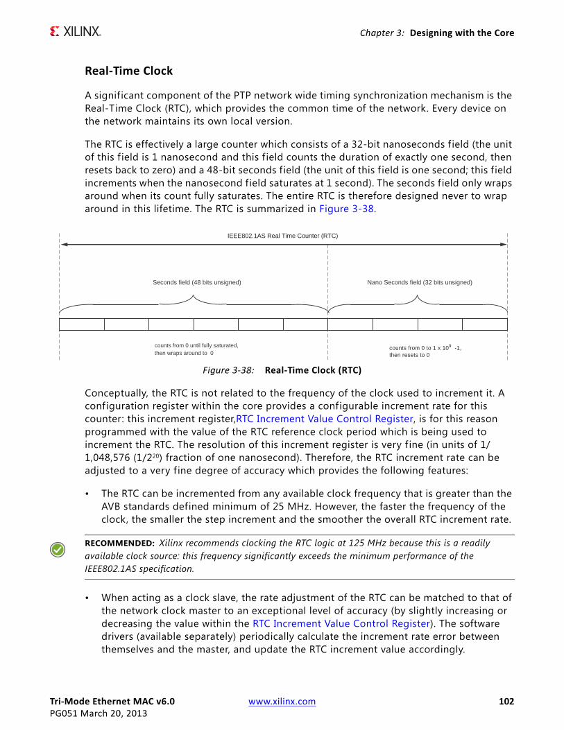
Tri-Mode Ethernet MAC v6.0 www.xilinx.com 102PG051 March 20, 2013
Chapter 3: Designing with the Core
Real-Time Clock
A signif icant component of the PTP network wide timing synchronization mechanism is the Real-Time Clock (RTC), which provides the common time of the network. Every device on the network maintains its own local version.
The RTC is effectively a large counter which consists of a 32-bit nanoseconds f ield (the unit of this f ield is 1 nanosecond and this f ield counts the duration of exactly one second, then resets back to zero) and a 48-bit seconds field (the unit of this f ield is one second; this f ield increments when the nanosecond field saturates at 1 second). The seconds field only wraps around when its count fully saturates. The entire RTC is therefore designed never to wrap around in this lifetime. The RTC is summarized in Figure 3-38.
Conceptually, the RTC is not related to the frequency of the clock used to increment it. A configuration register within the core provides a configurable increment rate for this counter: this increment register,RTC Increment Value Control Register, is for this reason programmed with the value of the RTC reference clock period which is being used to increment the RTC. The resolution of this increment register is very f ine (in units of 1/1,048,576 (1/220) fraction of one nanosecond). Therefore, the RTC increment rate can be adjusted to a very f ine degree of accuracy which provides the following features:
• The RTC can be incremented from any available clock frequency that is greater than the AVB standards defined minimum of 25 MHz. However, the faster the frequency of the clock, the smaller the step increment and the smoother the overall RTC increment rate.
RECOMMENDED: Xilinx recommends clocking the RTC logic at 125 MHz because this is a readily available clock source: this frequency significantly exceeds the minimum performance of the IEEE802.1AS specification.
• When acting as a clock slave, the rate adjustment of the RTC can be matched to that of the network clock master to an exceptional level of accuracy (by slightly increasing or decreasing the value within the RTC Increment Value Control Register). The software drivers (available separately) periodically calculate the increment rate error between themselves and the master, and update the RTC increment value accordingly.
X-Ref Target - Figure 3-38
Figure 3-38: Real-Time Clock (RTC)
Seconds field (48 bits unsigned) Nano Seconds field (32 bits unsigned)
counts from 0 until fully saturated,then wraps around to 0
counts from 0 to 1 x 10⁹ -1,then resets to 0
IEEE802.1AS Real Time Counter (RTC)

Tri-Mode Ethernet MAC v6.0 www.xilinx.com 103PG051 March 20, 2013
Chapter 3: Designing with the Core
The core also contains configuration registers, RTC Seconds Field Offset Control and RTC Nanoseconds Field Offset Control, which allow a large step change to be made to the RTC. This can be used to initialize the RTC, after power-up. It is also used to make periodic corrections, as required, by the software drivers when operating as a clock slave; however, if the increment rates are closely matched, these periodic step corrections are small.
RTC Implementation
Increment of Nanoseconds Field
Figure 3-39 shows the implementation used to create the RTC nanoseconds f ield. This is performed by the use of an implementation-specif ic 20-bit sub-nanoseconds field. The nanoseconds and sub-nanoseconds fields can be considered to be concatenated together. All RTC logic within the core is synchronous to the RTC Reference clock, rtc_clk .
X-Ref Target - Figure 3-39
Figure 3-39: Increment of Sub-Nanoseconds and Nanoseconds Field
Tri-Mode Ethernet MAC v6.0 www.xilinx.com 104PG051 March 20, 2013
Chapter 3: Designing with the Core
There are two stages to the implementation:
1. Controlled Frequency RTC
The RTC Increment Value illustrated in Figure 3-39 is set directly from the RTC Increment Value Control Register. The upper six bits of this register align with the lower six bits of the RTC nanoseconds f ield. The lower 20 bits of the RTC Increment Value align with the 20-bit sub-nanoseconds f ield. It is assumed that the frequency of the RTC reference clock is known by the processor to enable the increment value to be programmed correctly. For example, if the RTC is being clocked from a 125 MHz clock source, a nominal increment value of 8 ns should be programmed (by writing the value 0x800000 into the RTC Increment Value Control Register). However, if the microprocessor determines that this clock is drifting with respect to the grand master clock, it can revise this nominal 8 ns up or down by a very f ine degree of accuracy.
The “step 1” addition illustrated in Figure 3-39 (of current counter value plus increment) occurs on every clock cycle of the RTC reference clock. The result from this addition forms the new value of the “controlled frequency RTC” nanoseconds f ield. This controlled frequency RTC initializes to zero, following reset, and continues to increment smoothly on every RTC reference clock cycle by the current value contained in the RTC Increment Value Control Register.
Figure 3-39 illustrates that 26 bits have been reserved for the Increment Value, the upper 6 bits of which overlap into the nanoseconds f ield. For this reason, the largest per-cycle increment = 1 ns × 26 = 64 ns. The lowest clock period which is expected to increment this counter is 40 ns (corresponding to the 25 MHz MAC clock used at 100 Mb/s speeds). So this should satisfy all allowable clock periods.
2. Synchronized RTC
The value contained in the RTC Seconds Field Offset Control and RTC Nanoseconds Field Offset Control written by the microprocessor, is then applied to the free running “controlled frequency RTC” counter. This is used by the microprocessor to:
• Initialize the power-up value of the Synchronized RTC.
• Apply step corrections to the Synchronized RTC (when a slave), based on the timing PTP packets received from the Grand Master Clock RTC.
The “step 2” addition illustrated in Figure 3-39 (of controlled frequency RTC value plus offset) occurs on every clock cycle of the RTC reference clock. The result from this addition forms the new value of the Synchronized RTC nanoseconds field. It is this version of the RTC nanoseconds f ield which is made available as an output of the core – the rtc_nanosec_field[31:0] port.

Tri-Mode Ethernet MAC v6.0 www.xilinx.com 105PG051 March 20, 2013
Chapter 3: Designing with the Core
Increment of the Seconds Field
The RTC seconds f ield is, conceptually, implemented in a similar way to the nanoseconds f ield. The seconds f ield should be incremented by a value of one whenever the synchronized RTC nanoseconds field saturates at one-second. The RTC Seconds Field Offset Control and RTC Nanoseconds Field Offset Control allow the software to make large step corrections to the seconds f ield in a similar manner. Again, the step correction capability can be used to either initialize the RTC counter following reset, or to synchronize the local RTC to that of the Grand Master Clock (when the local device is acting as a clock slave).
Clock Outputs Based on the Synchronized RTC Nanoseconds Field
The clk8k (8 kHz clock) output, derived from the Synchronized RTC, is provided as an output from the core. The synchronized RTC counter, unlike the controlled frequency version, has no long-term drift (assuming the provided software drivers are used correctly). Therefore, the clk8k signal is synchronized exactly to the network RTC frequency.
The 8 kHz clock is the period of the shortest class measurement interval for an SR class as specified in IEEE802.1Q. This clock could also be useful for external applications (for example, a 1722 implementation of the AV traff ic).
Timestamping LogicNote: TEMAC supports IEEE 1588 timestamping.
Whenever a PTP packet, used with the Precise Timing Protocol (PTP), is transmitted or received (see Precise Timing Protocol Packet Buffers), a sample of the current value of the RTC is taken and made available for the software drivers to read. The hardware makes no distinction between frames carrying event or general PTP messages (as defined in IEEE 802.1AS); it always stores a timestamp value for Ethernet frames containing the Ethertype specified for PTP messages.
This timestamping of packets is a key element of the tight timing synchronization across the AVB network wide RTC, and these samples must be performed in hardware for accuracy. The hardware in this core therefore samples and captures the local nanoseconds RTC field for every PTP frame transmitted or received. These captured timestamps are stored in the Precise Timing Protocol Packet Buffers alongside the relevant PTP frame, and are read and used by the PTP software drivers.
IMPORTANT: It is actually the "controlled frequency RTC" nanoseconds field which is sampled by the timestamping logic rather than the synchronized RTC (see Figure 3-39). This is important when operating as a clock slave: the controlled frequency RTC always acts as a smooth counter and the synchronized RTC might suffer from occasional step changes (whenever a new offset adjustment is periodically applied by the software drivers). These step changes, avoided by using the controlled frequency RTC, could otherwise lead to errors in the various PTP calculations which are performed by the software drivers.
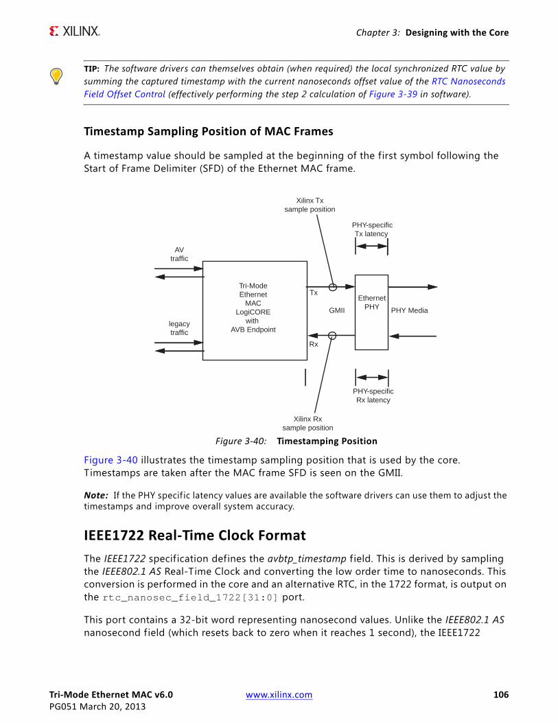
Tri-Mode Ethernet MAC v6.0 www.xilinx.com 106PG051 March 20, 2013
Chapter 3: Designing with the Core
TIP: The software drivers can themselves obtain (when required) the local synchronized RTC value by summing the captured timestamp with the current nanoseconds offset value of the RTC Nanoseconds Field Offset Control (effectively performing the step 2 calculation of Figure 3-39 in software).
Timestamp Sampling Position of MAC Frames
A timestamp value should be sampled at the beginning of the first symbol following the Start of Frame Delimiter (SFD) of the Ethernet MAC frame.
Figure 3-40 illustrates the timestamp sampling position that is used by the core. Timestamps are taken after the MAC frame SFD is seen on the GMII.
Note: If the PHY specif ic latency values are available the software drivers can use them to adjust the timestamps and improve overall system accuracy.
IEEE1722 Real-Time Clock FormatThe IEEE1722 specification defines the avbtp_timestamp f ield. This is derived by sampling the IEEE802.1 AS Real-Time Clock and converting the low order time to nanoseconds. This conversion is performed in the core and an alternative RTC, in the 1722 format, is output on the rtc_nanosec_field_1722[31:0] port.
This port contains a 32-bit word representing nanosecond values. Unlike the IEEE802.1 AS nanosecond field (which resets back to zero when it reaches 1 second), the IEEE1722
X-Ref Target - Figure 3-40
Figure 3-40: Timestamping Position
Tri-ModeEthernet
MACLogiCORE
with AVB Endpoint
legacytraffic
AVtraffic
EthernetPHYGMII
Tx
Rx
PHY Media
Xilinx Rxsample position
Xilinx Txsample position
PHY-specificTx latency
PHY-specificRx latency

Tri-Mode Ethernet MAC v6.0 www.xilinx.com 107PG051 March 20, 2013
Chapter 3: Designing with the Core
nanosecond f ield counts fully to 0xFFFFFFFF before wrapping around. The f ield therefore wraps around approximately every 4 seconds.
If the system is using the IEEE1722 functionality, this port can be sampled to create the avbtp_timestamp f ield. Otherwise this port can be ignored.
Precise Timing Protocol Packet BuffersThis chapter considers two of the logical components which are partly responsible for the AVB timing synchronization protocol.
• TX PTP Packet Buffer
• RX PTP Packet Buffer
These are both described in this chapter as they are closely related.
TX PTP Packet Buffer
The TX PTP packet buffer is illustrated in Figure 3-41. This packet buffer provides working memory to hold the PTP frames which are required for transmission. The software drivers, through the AXI4-Lite configuration bus, can read/modify/write the PTP frame contents, and whenever required, can request transmission of the appropriate PTP frames.
The PTP packet buffer is implemented in dual-port block RAM. Port A of the block RAM is connected to the configuration bus and all addresses in the buffer are read/writable. Port B of the block RAM is connected to the TX Arbiter module, allowing PTP frames to be read out of the block RAM and transmitted.
The TX PTP Packet Buffer is divided into eight identical buffer sections as illustrated. Each section contains 256 bytes, which are formatted as follows:
• The first byte, at address zero, contains a frame length f ield. This indicates how many bytes make up the PTP frame that is to be transmitted from this particular PTP buffer.
• The next seven bytes, from address 1 to 7, are reserved for future use.
• The PTP frame data itself is stored from address 8 onwards. The amount of addresses used is dependent on the indicated frame length f ield, which is different for each PTP frame type. Each PTP buffer provides a maximum of 244 bytes (more than that required for the largest PTP frame). Each PTP frame holds the entire MAC frame (with the exception of any required MAC padding or CRC - these are automatically inserted by the transmit logic) from the Destination Address f ield onwards.
• The top four addresses of each buffer, from address 0xFC to 0xFF are reserved for a timestamp field. At the beginning of PTP frame transmission from any of the eight buffers, the Timestamping Logic samples the Real-Time Clock. Following the end of PTP frame transmission, this captured timestamp is automatically written into this location to accompany the frame for which it was taken.
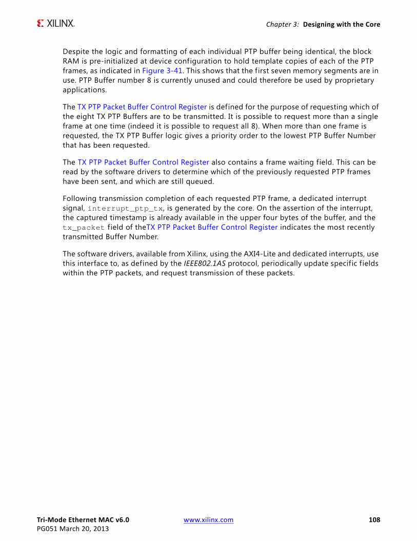
Tri-Mode Ethernet MAC v6.0 www.xilinx.com 108PG051 March 20, 2013
Chapter 3: Designing with the Core
Despite the logic and formatting of each individual PTP buffer being identical, the block RAM is pre-initialized at device configuration to hold template copies of each of the PTP frames, as indicated in Figure 3-41. This shows that the f irst seven memory segments are in use. PTP Buffer number 8 is currently unused and could therefore be used by proprietary applications.
The TX PTP Packet Buffer Control Register is defined for the purpose of requesting which of the eight TX PTP Buffers are to be transmitted. It is possible to request more than a single frame at one time (indeed it is possible to request all 8). When more than one frame is requested, the TX PTP Buffer logic gives a priority order to the lowest PTP Buffer Number that has been requested.
The TX PTP Packet Buffer Control Register also contains a frame waiting field. This can be read by the software drivers to determine which of the previously requested PTP frames have been sent, and which are still queued.
Following transmission completion of each requested PTP frame, a dedicated interrupt signal, interrupt_ptp_tx, is generated by the core. On the assertion of the interrupt, the captured timestamp is already available in the upper four bytes of the buffer, and the tx_packet f ield of theTX PTP Packet Buffer Control Register indicates the most recently transmitted Buffer Number.
The software drivers, available from Xilinx, using the AXI4-Lite and dedicated interrupts, use this interface to, as defined by the IEEE802.1AS protocol, periodically update specif ic f ields within the PTP packets, and request transmission of these packets.
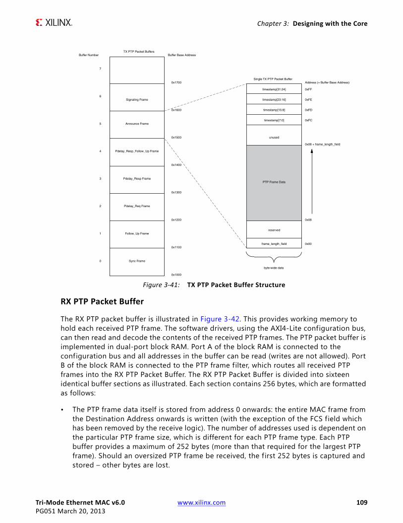
Tri-Mode Ethernet MAC v6.0 www.xilinx.com 109PG051 March 20, 2013
Chapter 3: Designing with the Core
RX PTP Packet Buffer
The RX PTP packet buffer is illustrated in Figure 3-42. This provides working memory to hold each received PTP frame. The software drivers, using the AXI4-Lite configuration bus, can then read and decode the contents of the received PTP frames. The PTP packet buffer is implemented in dual-port block RAM. Port A of the block RAM is connected to the configuration bus and all addresses in the buffer can be read (writes are not allowed). Port B of the block RAM is connected to the PTP frame filter, which routes all received PTP frames into the RX PTP Packet Buffer. The RX PTP Packet Buffer is divided into sixteen identical buffer sections as illustrated. Each section contains 256 bytes, which are formatted as follows:
• The PTP frame data itself is stored from address 0 onwards: the entire MAC frame from the Destination Address onwards is written (with the exception of the FCS f ield which has been removed by the receive logic). The number of addresses used is dependent on the particular PTP frame size, which is different for each PTP frame type. Each PTP buffer provides a maximum of 252 bytes (more than that required for the largest PTP frame). Should an oversized PTP frame be received, the f irst 252 bytes is captured and stored – other bytes are lost.
X-Ref Target - Figure 3-41
Figure 3-41: TX PTP Packet Buffer Structure
Tri-Mode Ethernet MAC v6.0 www.xilinx.com 110PG051 March 20, 2013
Chapter 3: Designing with the Core
• The top four addresses of each buffer, from address 0xFC to 0xFF are reserved for a timestamp field. At the beginning of PTP frame reception, the Timestamping Logic samples the Real-Time Clock. Following the end of PTP frame reception, this captured timestamp is automatically written into this location to accompany the frame for which it was taken.
Following reset, the first received PTP frame is written into Buffer Number 0. The next subsequent received PTP frame is written into the next available buffer — in this case number 1. This process continues with buffer number 2, 3, then 4, and so forth, being used. After receiving the 16th PTP frame (which would have been stored into buffer number 15), the count is reset, and then buffer number 0 is overwritten with the next received PTP frame. For this reason, at any one time, the RX PTP Packet Buffer is capable of storing the most recently received 16 PTP frames.
Following the completion of PTP frame reception, a dedicated interrupt signal, interrupt_ptp_rx, is generated by the core. On the assertion of the interrupt, the captured timestamp is already available in the upper four bytes of the buffer, and the rx_packet f ield of the RX PTP Packet Buffer Control Register indicates the most recently f illed Buffer Number. The software drivers, available from Xilinx, using the AXI4-Lite and dedicated interrupt, use this interface to decode, and then act on, the received PTP packet information.
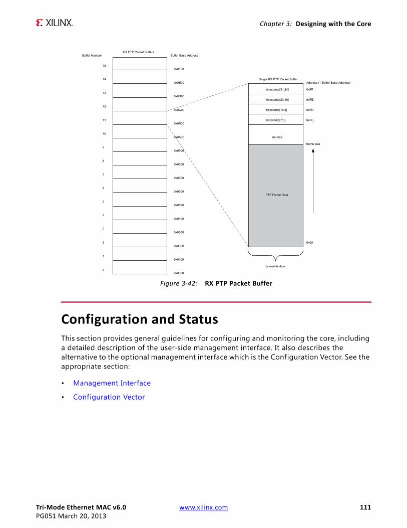
Tri-Mode Ethernet MAC v6.0 www.xilinx.com 111PG051 March 20, 2013
Chapter 3: Designing with the Core
Configuration and StatusThis section provides general guidelines for configuring and monitoring the core, including a detailed description of the user-side management interface. It also describes the alternative to the optional management interface which is the Configuration Vector. See the appropriate section:
• Management Interface
• Configuration Vector
X-Ref Target - Figure 3-42
Figure 3-42: RX PTP Packet Buffer
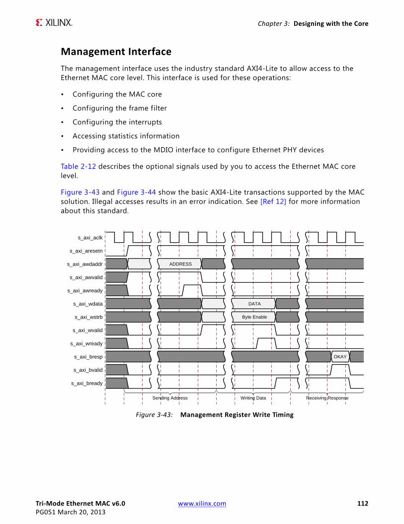
Tri-Mode Ethernet MAC v6.0 www.xilinx.com 112PG051 March 20, 2013
Chapter 3: Designing with the Core
Management InterfaceThe management interface uses the industry standard AXI4-Lite to allow access to the Ethernet MAC core level. This interface is used for these operations:
• Configuring the MAC core
• Configuring the frame filter
• Configuring the interrupts
• Accessing statistics information
• Providing access to the MDIO interface to configure Ethernet PHY devices
Table 2-12 describes the optional signals used by you to access the Ethernet MAC core level.
Figure 3-43 and Figure 3-44 show the basic AXI4-Lite transactions supported by the MAC solution. Illegal accesses results in an error indication. See [Ref 12] for more information about this standard.
X-Ref Target - Figure 3-43
Figure 3-43: Management Register Write Timing
s_axi_aclk
s_axi_aresetn
s_axi_awdaddr
s_axi_awvalid
s_axi_awready
s_axi_wdata
s_axi_wstrb
s_axi_wvalid
s_axi_wready
s_axi_bresp
s_axi_bvalid
s_axi_bready
ADDRESS
DATA
Byte Enable
OKAY
Sending Address Writing Data Receiving Response
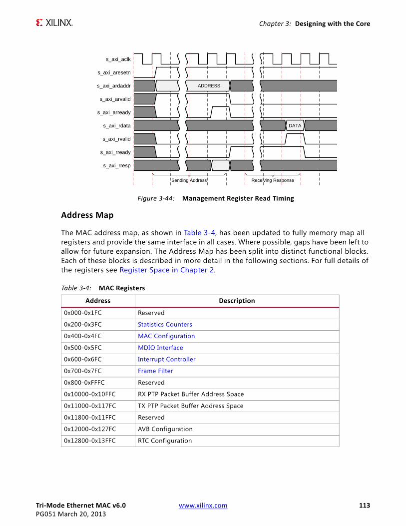
Tri-Mode Ethernet MAC v6.0 www.xilinx.com 113PG051 March 20, 2013
Chapter 3: Designing with the Core
Address Map
The MAC address map, as shown in Table 3-4, has been updated to fully memory map all registers and provide the same interface in all cases. Where possible, gaps have been left to allow for future expansion. The Address Map has been split into distinct functional blocks. Each of these blocks is described in more detail in the following sections. For full details of the registers see Register Space in Chapter 2.
X-Ref Target - Figure 3-44
Figure 3-44: Management Register Read Timing
Table 3-4: MAC Registers
Address Description
0x000-0x1FC Reserved
0x200-0x3FC Statistics Counters
0x400-0x4FC MAC Configuration
0x500-0x5FC MDIO Interface
0x600-0x6FC Interrupt Controller
0x700-0x7FC Frame Filter
0x800-0xFFFC Reserved
0x10000-0x10FFC RX PTP Packet Buffer Address Space
0x11000-0x117FC TX PTP Packet Buffer Address Space
0x11800-0x11FFC Reserved
0x12000-0x127FC AVB Configuration
0x12800-0x13FFC RTC Configuration
s_axi_aclk
s_axi_aresetn
s_axi_ardaddr
s_axi_arvalid
s_axi_arready
s_axi_rdata
s_axi_rvalid
s_axi_rready
s_axi_rresp
ADDRESS
DATA
Sending Address Receiving Response

Tri-Mode Ethernet MAC v6.0 www.xilinx.com 114PG051 March 20, 2013
Chapter 3: Designing with the Core
MAC Configuration
After the core is powered up and reset, you can reconfigure some of the core parameters from their defaults, such as flow control support and RX/TX VLAN support. Configuration changes can be written at any time, however, both receiver and transmitter configuration changes only take effect during interframe gaps. The exceptions to this are the configurable soft resets, which take effect immediately. See MAC Configuration Registers in Chapter 2.
MDIO Interface
Management Interface is also used to access the MDIO Interface of the TEMAC core; this interface is used to access the Managed Information Block of the PHY components attached to the TEMAC core and is only available when the management interface is enabled.
Introduction to MDIO
MDIO Bus System
Management Data Input/Output (MDIO) interface for access to Ethernet PHY devices for 1 Gb/s operation and slower speeds is defined in IEEE 802.3, clause 22. This two-wire interface consists of a Management Data Clock (MDC) and a shared serial data line (MDIO). The maximum permitted frequency of MDC is set at 2.5 MHz. Figure 3-45 illustrates an example MDIO bus system.
An Ethernet MAC is shown as the MDIO bus master (the Station Management (STA) entity). Two PHY devices are shown connected to the same bus, both of which are MDIO slaves (MDIO Managed Device (MMD) entities).
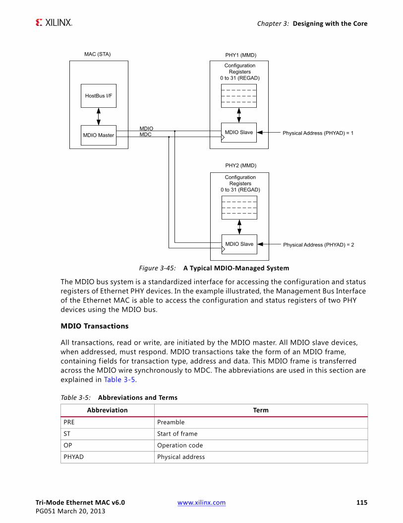
Tri-Mode Ethernet MAC v6.0 www.xilinx.com 115PG051 March 20, 2013
Chapter 3: Designing with the Core
The MDIO bus system is a standardized interface for accessing the configuration and status registers of Ethernet PHY devices. In the example illustrated, the Management Bus Interface of the Ethernet MAC is able to access the configuration and status registers of two PHY devices using the MDIO bus.
MDIO Transactions
All transactions, read or write, are initiated by the MDIO master. All MDIO slave devices, when addressed, must respond. MDIO transactions take the form of an MDIO frame, containing f ields for transaction type, address and data. This MDIO frame is transferred across the MDIO wire synchronously to MDC. The abbreviations are used in this section are explained in Table 3-5.
X-Ref Target - Figure 3-45
Figure 3-45: A Typical MDIO-Managed System
Table 3-5: Abbreviations and Terms
Abbreviation Term
PRE Preamble
ST Start of frame
OP Operation code
PHYAD Physical address

Tri-Mode Ethernet MAC v6.0 www.xilinx.com 116PG051 March 20, 2013
Chapter 3: Designing with the Core
Write Transaction
Figure 3-46 shows a Write transaction across the MDIO; this is defined by OP = 01. The addressed PHY (PHYAD) device takes the 16-bit word in the data f ield and writes it to the register at REGAD.
Read Transaction
Figure 3-47 shows a Read transaction; this is defined by OP = 10. The addressed PHY (PHYAD) device returns the 16-bit word from the register at REGAD. For details of the register map of PHY layer devices and a fuller description of the operation of the MDIO interface itself, see [Ref 8].
REGAD Register address
TA Turnaround
X-Ref Target - Figure 3-46
Figure 3-46: MDIO Write Transaction
X-Ref Target - Figure 3-47
Figure 3-47: MDIO Read Transaction
Table 3-5: Abbreviations and Terms (Cont’d)
Abbreviation Term
Z1 1 1 0 0 1 P4 P3 P2 P1 P0 R4R3R2R1R0 1 0 D15D14
D13D12
D11D10
D9D8
D7D6
D5D4
D3D2
D1D0
1 ZZZ
mdc
mdio
IDLE IDLE32 bitsPRE
ST OP PHYAD REGAD TA 16-bit WRITE DATA
GEMAC drives MDIO
Z1 1 1 0 1 0 P4 P3 P2 P1 P0 R4R3R2R1R0 Z 0 D15D14
D13D12
D11D10
D9D8
D7D6
D5D4
D3D2
D1D0
1 ZZZ
mdc
mdio
IDLE IDLE32 bitsPRE
ST OP PRTAD REGAD TA 16-bit READ DATA
MAC drives MDIO PHY drives MDIO
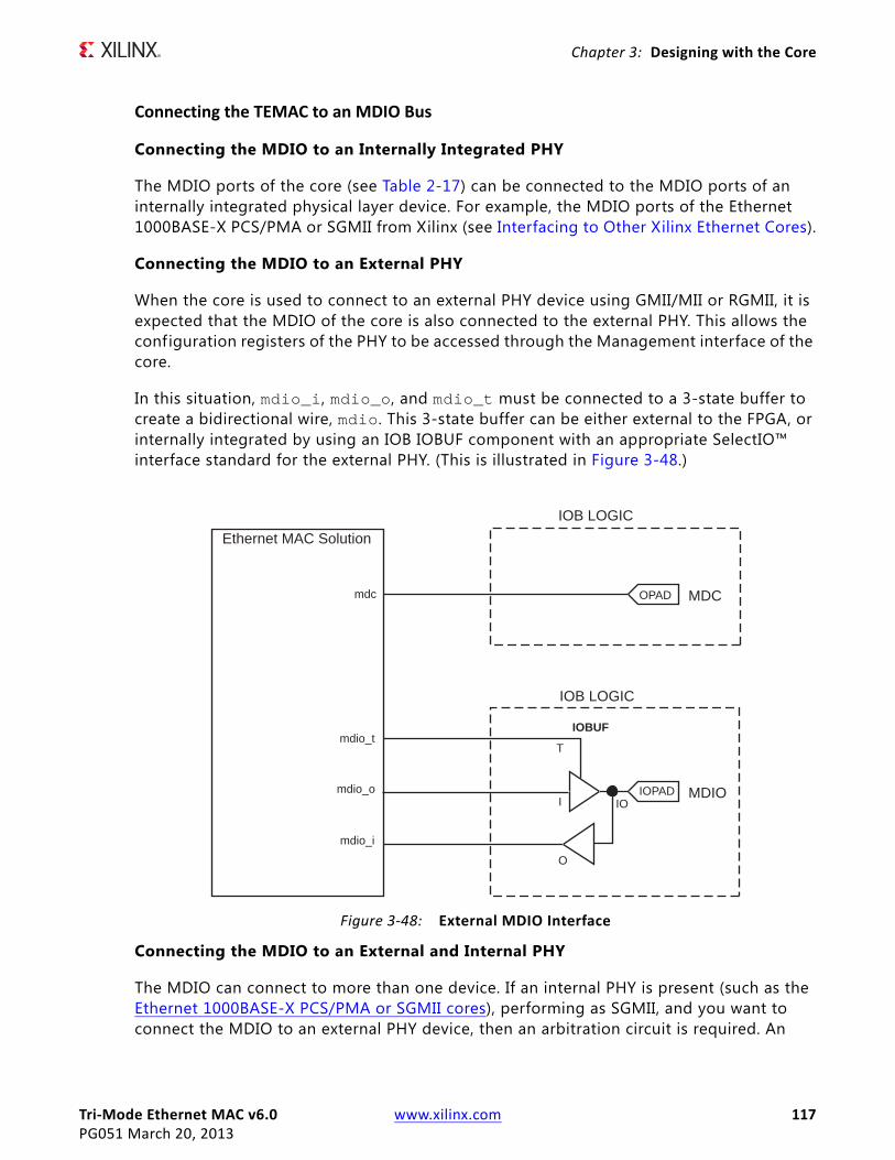
Tri-Mode Ethernet MAC v6.0 www.xilinx.com 117PG051 March 20, 2013
Chapter 3: Designing with the Core
Connecting the TEMAC to an MDIO Bus
Connecting the MDIO to an Internally Integrated PHY
The MDIO ports of the core (see Table 2-17) can be connected to the MDIO ports of an internally integrated physical layer device. For example, the MDIO ports of the Ethernet 1000BASE-X PCS/PMA or SGMII from Xilinx (see Interfacing to Other Xilinx Ethernet Cores).
Connecting the MDIO to an External PHY
When the core is used to connect to an external PHY device using GMII/MII or RGMII, it is expected that the MDIO of the core is also connected to the external PHY. This allows the configuration registers of the PHY to be accessed through the Management interface of the core.
In this situation, mdio_i, mdio_o, and mdio_t must be connected to a 3-state buffer to create a bidirectional wire, mdio. This 3-state buffer can be either external to the FPGA, or internally integrated by using an IOB IOBUF component with an appropriate SelectIO™ interface standard for the external PHY. (This is illustrated in Figure 3-48.)
Connecting the MDIO to an External and Internal PHY
The MDIO can connect to more than one device. If an internal PHY is present (such as the Ethernet 1000BASE-X PCS/PMA or SGMII cores), performing as SGMII, and you want to connect the MDIO to an external PHY device, then an arbitration circuit is required. An
X-Ref Target - Figure 3-48
Figure 3-48: External MDIO Interface
IOB LOGIC
OPAD
O
I IO
T
IOPAD
IOB LOGIC
IOBUF
Ethernet MAC Solution
mdc
mdio_t
mdio_o
mdio_i
MDC
MDIO
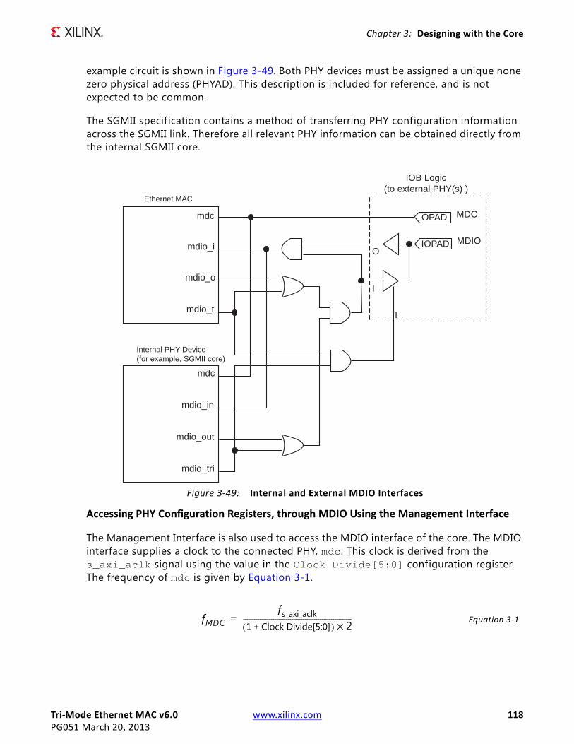
Tri-Mode Ethernet MAC v6.0 www.xilinx.com 118PG051 March 20, 2013
Chapter 3: Designing with the Core
example circuit is shown in Figure 3-49. Both PHY devices must be assigned a unique none zero physical address (PHYAD). This description is included for reference, and is not expected to be common.
The SGMII specif ication contains a method of transferring PHY configuration information across the SGMII link. Therefore all relevant PHY information can be obtained directly from the internal SGMII core.
Accessing PHY Configuration Registers, through MDIO Using the Management Interface
The Management Interface is also used to access the MDIO interface of the core. The MDIO interface supplies a clock to the connected PHY, mdc. This clock is derived from the s_axi_aclk signal using the value in the Clock Divide[5:0] configuration register. The frequency of mdc is given by Equation 3-1.
Equation 3-1
X-Ref Target - Figure 3-49
Figure 3-49: Internal and External MDIO Interfaces
mdc
mdio_i
mdio_o
mdio_t
mdc
mdio_in
mdio_out
mdio_tri
OPAD MDC
IOPAD MDIO
IOB Logic(to external PHY(s) )
T
I
O
Ethernet MAC
Internal PHY Device(for example, SGMII core)
fMDCfs_axi_aclk
1 Clock Divide[5:0]+( ) 2×----------------------------------------------------------=
Tri-Mode Ethernet MAC v6.0 www.xilinx.com 119PG051 March 20, 2013
Chapter 3: Designing with the Core
The frequency of mdc given by Equation 3-1 should not exceed 2.5 MHz to comply with the IEEE 802.3-2008 specif ication for this interface. To prevent mdc from being out of specification, the Clock Divide[5:0] value powers up at 00000, and while this value is in the register, it is impossible to enable the MDIO interface.
For details of the register map of PHY layer devices and a fuller description of the operation of the MDIO interface itself, see IEEE 802.3-2008.
MDIO Configuration and Control
Access to the MDIO interface through the management interface is entirely register mapped.
To perform an MDIO write the write data must first be written to the MDIO Write Data register, shown in Table 2-36, The MDIO write transaction is then initiated by a write to the MDIO Control Word register, shown in Table 2-35, with Initiate (Bit[11]) set to 0x1, OP (Bits[15:14]) set to 0x1 and the PHYAD and REGAD set according to the PHY and Register being accessed. This triggers the MDIO Ready bit to deassert and it remains deasserted until the MDIO transaction has completed.
To perform an MDIO read, the read transaction is initiated by a write to the MDIO Control Word register, shown in Table 2-35, with Initiate (Bit[11]) set to 0x1, OP (Bits[15:14]) set to 0x2 and the PHYAD and REGAD set according to the PHY and Register being accessed. This triggers the MDIO Ready bit to deassert and it remains deasserted until the MDIO transaction has completed. When the MDIO Ready is re-asserted the read data is ready to be read from the MDIO Read data register, shown in Table 2-37.
Note: It is possible to either poll the MDIO Control register or the MDIO Read Data register to check the status of MDIO Ready; alternatively the MAC interrupt can be used (see Interrupt Controller).
Interrupt ControllerAn Interrupt Block is implemented in the Tri-Mode Ethernet MAC solution to assert an interrupt when a pending MDIO transaction has completed. Interrupt registers are shown in Table 2-38.
Configuration VectorIf the optional management interface is omitted from the core, all of the relevant configuration signals are brought out of the core. These signals are bundled into the rx_configuration_vector and the tx_configuration_vector signals. The bit mapping of these signals are defined in Table 2-69 and Table 2-70.
You can permanently set the vector bits to logic 0 or 1 or change the configuration vector signals at any time; however, with the exception of the reset signals, they do not take effect until the current frame has completed transmission or reception.
Tri-Mode Ethernet MAC v6.0 www.xilinx.com 120PG051 March 20, 2013
Chapter 3: Designing with the Core
Frame Filter
When the frame filter is selected with no management interface, only a subset of its functionality is available. Because there is no user access to internal registers it is not possible to update the configurable frame filters; these are therefore not generated as part of the core. However, the basic Destination Address f iltering is still available and enables the MAC to identify/filter the Broadcast address, a User supplied Pause/Unicast Address and the Special Pause Multicast Address. In this configuration it is assumed that the user-supplied Pause address is the same as the MAC Unicast address. A packet matching this f ilter is only treated as a pause frame if it meets all other criteria to identify a pause frame.
TEMAC Configuration SettingsThis section discusses unusual configuration options. These can be set by either method (Management Interface or the Configuration Vector).
Half-Duplex Configuration SettingsWhen the core is generated with half-duplex capability, the transmitter and receiver can be independently configured between full and half-duplex modes. This functionality is made available for full flexibility in unusual applications, for example, Ethernet protocol testers. However, for legal and predictable behavior in Ethernet networks, always configure transmitter and receiver duplex modes identically.
Half-Duplex and Flow Control Configuration SettingsThe IEEE802.3 specif ication defines the flow control functionality only for full-duplex applications.
Configuration of the TEMAC allows Flow Control functionality and Duplex mode to be configured independently. However, Flow Control is enabled only in full-duplex mode. Be sure the following conditions are met.
• When operating half-duplex mode, always disable Flow Control.
• When operating in full-duplex mode, Flow Control can optionally be enabled.
MAC Address SettingsUnder all core generation settings, the core contains a configurable Pause frame MAC Source Address (see MAC Configuration Registers) and the use of configuration vectors allows this to be set independently for RX and TX. This MAC Address is used by the flow control logic; received pause frames are matched against this address appearing in the

Tri-Mode Ethernet MAC v6.0 www.xilinx.com 121PG051 March 20, 2013
Chapter 3: Designing with the Core
Destination Address f ield; pause frames initiated by the core place this MAC Address into the Source Address field of a transmitted pause frame.
When the TEMAC solution is generated with the optional frame filter, the core contains a configurable Unicast Address (see MAC Configuration Registers). This is used by the frame filter to match against this address appearing in the Destination Address f ield of all received frames. The core, for full flexibility, allows the Pause frame MAC Source Address and the Unicast Address (when present) to be configured independently. However, under standard network operating conditions the Pause frame MAC Source Address should be set to the Unicast Address.
The core, when generated without a management interface, has independent RX and TX Pause Frame MAC source Address control; these should be set to the same value.
AVB Endpoint When enabling AVB Endpoint operation, disable flow control and jumbo mode and use only in full-duplex mode.
Note: The AVB Endpoint is only available if the AXI4-Lite management interface is included and therefore there is no configuration vector control available.
Physical Interface for the 10 Mb/s and 100 Mb/s Only Ethernet MAC IP CoreThe HDL example design, only supplied with the 10 Mb/s or 100 Mb/s IP core, provides an MII interface. This is typically used to connect the MAC to an external PHY device.
The Media Independent Interface (MII), defined in IEEE Std 802.3-2008, clause 22 is a parallel interface that connects a 10 Mb/s and/or 100 Mb/s capable MAC to the physical sublayers.
For 7 series and Zynq™-7000 families it depends on the type of I/O used: HR I/O supports MII at 3.3V or lower and HP I/O only supports 1.8V or lower. Therefore an external voltage converter is required to interoperate with any multi-standard PHY.
MII Transmitter InterfaceThe logic required to implement the MII transmitter logic is illustrated in Figure 3-50. mii_tx_clk is provided by the external PHY device connected to the MII. As shown, this is placed onto global clock routing to provide the clock for all transmitter logic, both within the core and for the user-side logic which connects to the TX AXI4-Stream interface of the core. Alternatively, for devices containing regional clock resources, the BUFG of Figure 3-50 can be replaced with a BUFR primitive.

Tri-Mode Ethernet MAC v6.0 www.xilinx.com 122PG051 March 20, 2013
Chapter 3: Designing with the Core
To match the user data rate (which uses an 8-bit datapath) and the MII (which uses a 4-bit datapath), the TX AXI4-Stream interface is throttled, using tx_axis_mac_tready, under control of the MAC to limit data transfers to every other cycle.
Figure 3-50 also illustrates how to use the physical transmitter interface of the core to create an external MII. The signal names and logic shown in this f igure exactly match those delivered with the example design. Figure 3-50 shows that the output transmitter signals are registered in device IOBs before driving them to the device pads.
MII Receiver InterfaceThe logic required to implement the MII receiver logic is also illustrated in Figure 3-50. mii_rx_clk is provided by the external PHY device connected to the MII. As illustrated, this is placed onto global clock routing to provide the clock for all receiver logic, both within the core and for the user-side logic which connects to the RX AXI4-Stream interface of the TEMAC. Alternatively, for devices containing regional clock resources, the BUFG of Figure 3-50 can be replaced with a BUFR primitive.
To match the user data rate, which uses an 8-bit datapath and the MII, which uses a 4-bit datapath, the RX AXI4-Stream interface is throttled, using rx_axis_mac_tvalid, under control of the MAC to limit data transfers to every other cycle.
Figure 3-50 also illustrates how to use the physical receiver interface of the core to create an external MII. The signal names and logic shown in this f igure exactly match those delivered with the example design. Figure 3-50 shows that the input receiver signals are registered in device IOBs before routing them to the core.
Multiple Core Instances with the MIIBecause both mii_tx_clk and mii_rx_clk are both sourced by the external PHY device connected to the MII, it is not possible to share transmitter or receiver clock resources across multiple instantiations of the core. Each instance of the core requires its own independent clocking resources. Therefore the logic of Figure 3-50 must be duplicated for each instance of the core.

Tri-Mode Ethernet MAC v6.0 www.xilinx.com 123PG051 March 20, 2013
Chapter 3: Designing with the Core
X-Ref Target - Figure 3-50
Figure 3-50: MII Transmitter, Receiver and Clock Logic For All Devices

Tri-Mode Ethernet MAC v6.0 www.xilinx.com 124PG051 March 20, 2013
Chapter 3: Designing with the Core
Physical Interfaces for 1 Gb/s Only Ethernet MAC IP CoreThe HDL example design supplied with the core for 1 Gb/s only operation provides either a GMII or RGMII interface. These are typically used to connect the MAC to an external PHY device.
The Gigabit Media Independent Interface (GMII), defined in IEEE Std 802.3-2008, clause 35, is used to connect a 1 Gb/s capable MAC to the physical sublayers.
For 7 series and Zynq™-7000 families it depends on the type of I/O used: HR I/O supports GMII at 3.3V or lower and HP I/O only supports 1.8V or lower. Therefore an external voltage converter is required to interoperate with any multi-standard PHY for GMII.
The Reduced Gigabit Media Independent Interface (RGMII) is an alternative to the GMII and achieves a 50% reduction in the pin count compared with GMII. Therefore, this is often favored over GMII by Printed Circuit Board (PCB) designers. This configuration is achieved with the use of double-data-rate (DDR) flip-flops.
For 7 series and Zynq-7000 families it depends on the type of I/O used: HR I/O supports RGMII at 2.5V or lower and HP I/O only supports 1.8V or lower. Despite this being the defined RGMII voltage, most PHYs require 2.5V and therefore an external voltage converter is required to interoperate with any multi-standard PHY for RGMII.
See the appropriate section for more information.
• Gigabit Media Independent Interface (GMII)
• Reduced Gigabit Media Independent Interface (RGMII)
Gigabit Media Independent Interface (GMII)
GMII Transmitter Interface
The logic required to implement the GMII transmitter logic is shown in Figure 3-51. The gtx_clk is a user-supplied 125 MHz reference clock source. As illustrated, this is placed onto global clock routing to provide the clock for all transmitter logic, both within the core and for the user-side logic that connects to the TX AXI4-Stream interface of the core.
Figure 3-51 illustrates how to use the physical transmitter interface of the core to create an external GMII. The signal names and logic shown in this f igure exactly match those delivered with the example design for a Virtex®-7 device when the GMII is selected. If other families are chosen, equivalent primitives specif ic to that family are used in the example design.

Tri-Mode Ethernet MAC v6.0 www.xilinx.com 125PG051 March 20, 2013
Chapter 3: Designing with the Core
Figure 3-51 shows that the output transmitter signals are registered in device IOBs before driving them to the device pads. The logic required to forward the transmitter clock is also shown. This logic uses an IOB output Double-Data-Rate (DDR) register so that the clock signal produced incurs exactly the same delay as the data and control signals.
This clock signal, gmii_tx_clk , is inverted with respect to gtx_clk so that the rising edge of gmii_tx_clk occurs in the center of the data valid window, therefore maximizing setup and hold times across the interface.
The half-duplex signals gmii_col and gmii_crs are asynchronous to the transmit clock. These are routed through PADs and IOBs and then input to the core.
X-Ref Target - Figure 3-51
Figure 3-51: GMII Transmitter Logic and Clock Logic
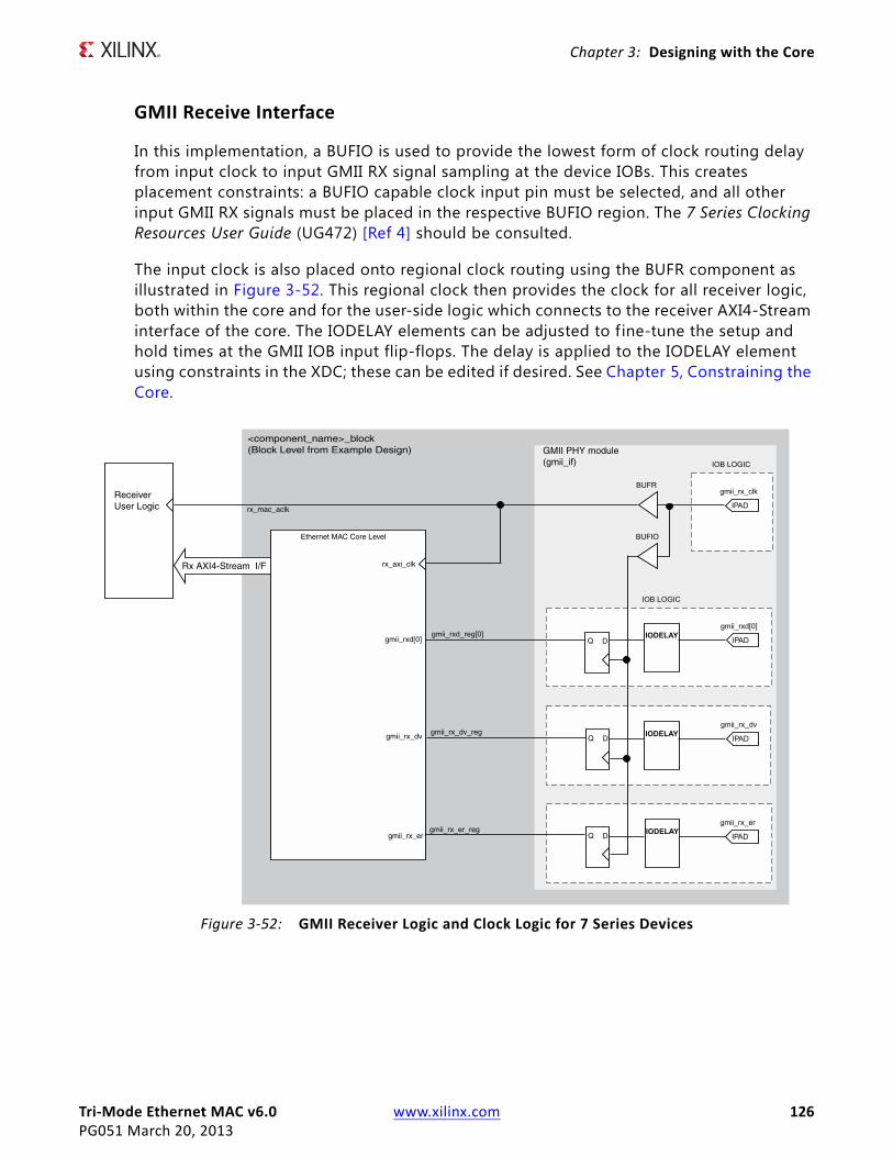
Tri-Mode Ethernet MAC v6.0 www.xilinx.com 126PG051 March 20, 2013
Chapter 3: Designing with the Core
GMII Receive Interface
In this implementation, a BUFIO is used to provide the lowest form of clock routing delay from input clock to input GMII RX signal sampling at the device IOBs. This creates placement constraints: a BUFIO capable clock input pin must be selected, and all other input GMII RX signals must be placed in the respective BUFIO region. The 7 Series Clocking Resources User Guide (UG472) [Ref 4] should be consulted.
The input clock is also placed onto regional clock routing using the BUFR component as illustrated in Figure 3-52. This regional clock then provides the clock for all receiver logic, both within the core and for the user-side logic which connects to the receiver AXI4-Stream interface of the core. The IODELAY elements can be adjusted to f ine-tune the setup and hold times at the GMII IOB input flip-flops. The delay is applied to the IODELAY element using constraints in the XDC; these can be edited if desired. See Chapter 5, Constraining the Core.
X-Ref Target - Figure 3-52
Figure 3-52: GMII Receiver Logic and Clock Logic for 7 Series Devices

Tri-Mode Ethernet MAC v6.0 www.xilinx.com 127PG051 March 20, 2013
Chapter 3: Designing with the Core
Clock Sharing across Multiple Cores with GMII for 1 Gb/s Operation
When multiple instances of the core are instantiated in a design, transmitter clock resources can be shared across all core instances; receiver clock resources cannot be shared and are independent for each core instance.
Figure 3-53 shows clock resource sharing across multiple instantiations of the core when using GMII at 1 Gb/s. For all instantiations, gtx_clk can be shared between multiple cores, resulting in a common clock domain across the device. The receiver clocks cannot be shared. Each core is provided with its own local version of gmii_rx_clk from the connected external PHY device as shown in Figure 3-53.
Figure 3-53 illustrates two cores. However, more can be added using the same principal. This is done by instantiating the cores using the block level (from the example design) and sharing gtx_clk across all instantiations. The receiver clock, which cannot be shared, is unique for every instance of the core.
X-Ref Target - Figure 3-53
Figure 3-53: Clock Resource Sharing for 1 Gb/s GMII in 7 Series Devices

Tri-Mode Ethernet MAC v6.0 www.xilinx.com 128PG051 March 20, 2013
Chapter 3: Designing with the Core
Reduced Gigabit Media Independent Interface (RGMII)The logic required to implement the RGMII transmitter logic is shown in Figure 3-54. The gtx_clk is a user-supplied 125 MHz reference clock source which is placed onto global clock routing to provide the clock for all transmitter logic, both within the core and for the user-side logic which connects to the transmitter AXI4-Stream interface of the core.
Figure 3-54 shows how to use the physical transmitter interface of the core to create an external RGMII. The signal names and logic shown in this f igure exactly match those delivered with the example design. Figure 3-54 shows that the output transmitter signals are registered in device IOBs, using DDR registers, before driving them to the device pads.
For 7 series and Zynq-7000 families it depends on the type of I/O used: HR I/O supports RGMII at 2.5V or lower and HP I/O only supports 1.8V or lower. Despite this being the defined RGMII voltage, most PHYs require 2.5V and therefore an external voltage converter is required to interoperate with any multi-standard PHY when using 7 series HP I/O.
The logic required to forward the transmitter clock is also shown. This logic uses an IOB output Double-Data-Rate (DDR) register so that the clock signal produced incurs exactly the same delay as the data and control signals. However, the clock signal is then routed though an output delay element (IODELAY) before connecting to the device pad. The result of this is to create a 2 ns delay, which places the rgmii_txc forwarded clock in the center of the data valid window for forwarded RGMII data and control signals.

Tri-Mode Ethernet MAC v6.0 www.xilinx.com 129PG051 March 20, 2013
Chapter 3: Designing with the Core
X-Ref Target - Figure 3-54
Figure 3-54: RGMII Transmitter Logic and Clock Logic for 7 Series Using HP I/O

Tri-Mode Ethernet MAC v6.0 www.xilinx.com 130PG051 March 20, 2013
Chapter 3: Designing with the Core
Transmitter Logic for 7 Series Using HR I/O
HR I/O do not include ODELAY components and another method is required to introduce the required 2 ns offset between the clock and data.
The logic required to implement the RGMII transmitter logic is illustrated in Figure 3-55. The gtx_clk and gtx_clk90 signals are user-supplied 125 MHz reference clock sources with gtx_clk90 having a 90ο phase shift with respect to gtx_clk . These are placed onto global clock routing to provide the clocks for all transmitter logic. The gtx_clk is used as the clock for the RGMII data and control. It is used both within the core and for the user-side logic which connects to the transmitter AXI4-Stream interface of the core. The gtx_clk90 is used for the RGMII clock only.
Figure 3-55 shows how to use the physical transmitter interface of the core to create an external RGMII. The signal names and logic shown in this f igure exactly match those delivered with the example design. Figure 3-55 shows that the output transmitter signals are registered in device IOBs, using DDR registers, before driving them to the device pads.
The logic required to forward the transmitter clock is also shown. This logic uses an IOB output Double-Data-Rate (DDR) register so that the clock signal produced incurs exactly the same delay as the data and control signals. However, the clock signal uses the 90ο phase shifted version of the clock. The result of this is to create a 2 ns delay, which places the rgmii_txc forwarded clock in the center of the data valid window for forwarded RGMII data and control signals.
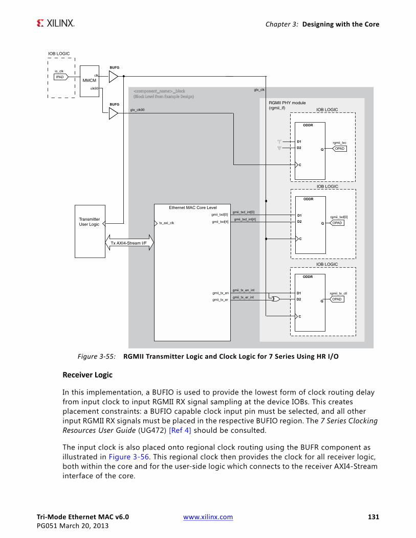
Tri-Mode Ethernet MAC v6.0 www.xilinx.com 131PG051 March 20, 2013
Chapter 3: Designing with the Core
Receiver Logic
In this implementation, a BUFIO is used to provide the lowest form of clock routing delay from input clock to input RGMII RX signal sampling at the device IOBs. This creates placement constraints: a BUFIO capable clock input pin must be selected, and all other input RGMII RX signals must be placed in the respective BUFIO region. The 7 Series Clocking Resources User Guide (UG472) [Ref 4] should be consulted.
The input clock is also placed onto regional clock routing using the BUFR component as illustrated in Figure 3-56. This regional clock then provides the clock for all receiver logic, both within the core and for the user-side logic which connects to the receiver AXI4-Stream interface of the core.
X-Ref Target - Figure 3-55
Figure 3-55: RGMII Transmitter Logic and Clock Logic for 7 Series Using HR I/O
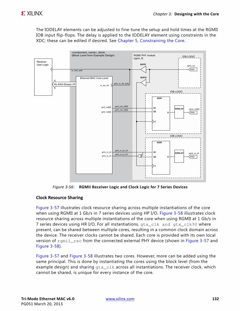
Tri-Mode Ethernet MAC v6.0 www.xilinx.com 132PG051 March 20, 2013
Chapter 3: Designing with the Core
The IODELAY elements can be adjusted to fine-tune the setup and hold times at the RGMII IOB input flip-flops. The delay is applied to the IODELAY element using constraints in the XDC; these can be edited if desired. See Chapter 5, Constraining the Core.
Clock Resource Sharing
Figure 3-57 illustrates clock resource sharing across multiple instantiations of the core when using RGMII at 1 Gb/s in 7 series devices using HP I/O. Figure 3-58 illustrates clock resource sharing across multiple instantiations of the core when using RGMII at 1 Gb/s in 7 series devices using HR I/O. For all instantiations, gtx_clk and gtx_clk90 where present, can be shared between multiple cores, resulting in a common clock domain across the device. The receiver clocks cannot be shared. Each core is provided with its own local version of rgmii_rxc from the connected external PHY device (shown in Figure 3-57 and Figure 3-58).
Figure 3-57 and Figure 3-58 illustrates two cores. However, more can be added using the same principal. This is done by instantiating the cores using the block level (from the example design) and sharing gtx_clk across all instantiations. The receiver clock, which cannot be shared, is unique for every instance of the core.
X-Ref Target - Figure 3-56
Figure 3-56: RGMII Receiver Logic and Clock Logic for 7 Series Devices
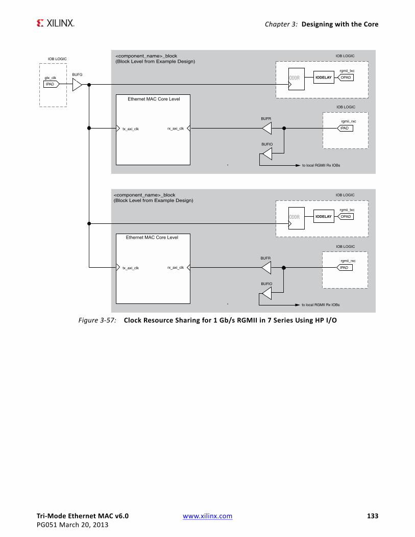
Tri-Mode Ethernet MAC v6.0 www.xilinx.com 133PG051 March 20, 2013
Chapter 3: Designing with the Core
X-Ref Target - Figure 3-57
Figure 3-57: Clock Resource Sharing for 1 Gb/s RGMII in 7 Series Using HP I/O
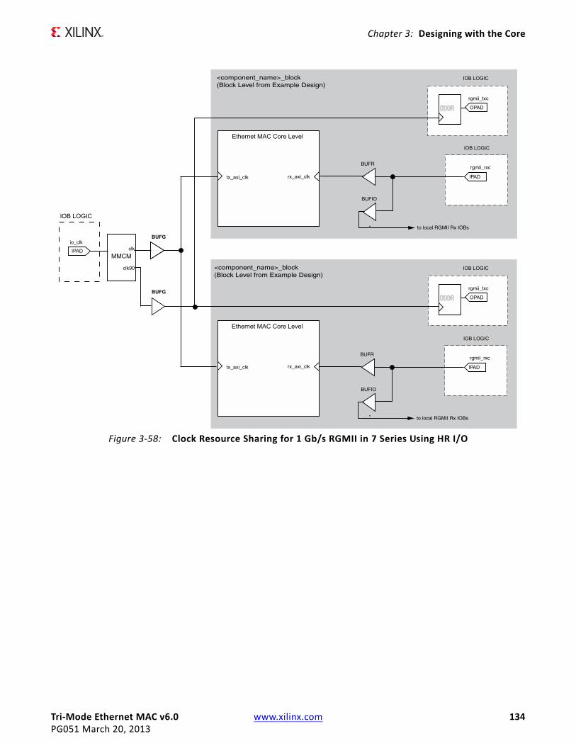
Tri-Mode Ethernet MAC v6.0 www.xilinx.com 134PG051 March 20, 2013
Chapter 3: Designing with the Core
X-Ref Target - Figure 3-58
Figure 3-58: Clock Resource Sharing for 1 Gb/s RGMII in 7 Series Using HR I/O
Tri-Mode Ethernet MAC v6.0 www.xilinx.com 135PG051 March 20, 2013
Chapter 3: Designing with the Core
Physical Interfaces for Tri-Speed (10 Mb/s, 100 Mb/s, and 1 Gb/s) Ethernet MAC IP CoreThe HDL example design supplied with the core for Tri-speed operation provides either a GMII or RGMII interface. These are typically used to connect the MAC to an external PHY device.
The Media Independent Interface (MII), defined in [Ref 8], clause 22, is a parallel interface that connects a 10 Mb/s and/or 100 Mb/s capable MAC to the physical sublayers. The Gigabit Media Independent Interface (GMII), defined in [Ref 8], clause 35, is an extension of the MII and is used to connect a 1 Gb/s capable MAC to the physical sublayers. MII can be considered a subset of GMII, and as a result, GMII/MII can carry Ethernet traff ic at 10 Mb/s, 100 Mb/s and 1 Gb/s.
For 7 series and Zynq™-7000 families it depends on the type of I/O used: HR I/O supports GMII at 3.3V or lower and HP I/O only supports 1.8V or lower. Therefore an external voltage converter is required to interoperate with any multi-standard PHY for GMII.
The Reduced Gigabit Media Independent Interface (RGMII) is an alternative to the GMII/MII. RGMII can carry Ethernet traff ic at 10 Mb/s, 100 Mb/s and 1 Gb/s and achieves a 50% reduction in the pin count compared with GMII; this is achieved with the use of double-data-rate (DDR) flip-flops. RGMII is therefore often favored over GMII by PCB designers. A further advantage of the RGMII implementation is that, unlike GMII/MII, clock resources for the transmitter can be shared across multiple core instances. This results in signif icant clock resource savings when implementing multiple cores in a design.
For 7 series and Zynq-7000 families it depends on the type of I/O used: HR I/O supports RGMII at 2.5V or lower and HP I/O only supports 1.8V or lower. Despite this being the defined RGMII voltage most PHYs require 2.5V and therefore an external voltage converter is required to interoperate with any multi-standard PHY for RGMII.
See the appropriate section for more information.
• Gigabit Media Independent Interface (GMII)
• Reduced Gigabit Media Independent Interface (RGMII)

Tri-Mode Ethernet MAC v6.0 www.xilinx.com 136PG051 March 20, 2013
Chapter 3: Designing with the Core
Gigabit Media Independent Interface (GMII)
GMII Transmitter Interface
The logic required to implement the GMII transmitter logic is illustrated in Figure 3-59. The gtx_clk is a user-supplied 125 MHz reference clock source for use at 1 Gb/s. mii_tx_clk is sourced by the external PHY device for use at 10 Mb/s and 100 Mb/s speeds. Consequently a global clock multiplexer, a BUFGMUX, is used to switch the clock source depending on the operating speed. The output from this BUFGMUX provides the transmitter clock for the core and user logic as illustrated in Figure 3-59.
Closely linked to the clock logic is the use of the tx_enable clock enable derivation. This must be provided to the Ethernet MAC core level. All user logic uses the AXI4-Stream interface handshaking to throttle the data to allow for the differing data widths between the 4-bit MII and the cores 8-bit user datapath.
Figure 3-59 also illustrates how to use the physical transmitter interface of the core to create an external GMII. The signal names and logic shown in this f igure exactly match those delivered with the example design for a Virtex-7 device when the GMII is selected. If other families are chosen, equivalent primitives specif ic to that family are used in the example design.
As shown in Figure 3-59, the output transmitter signals are registered in device IOBs before driving them to the device pads. The logic required to forward the transmitter clock for 1 Gb/s operation is also shown. This logic uses an IOB output Double-Data-Rate (DDR) register so that the clock signal produced incurs exactly the same delay as the data and control signals. This clock signal, gmii_tx_clk , is inverted with respect to gtx_clk so that the rising edge of gmii_tx_clk occurs in the center of the data valid window, therefore maximizing setup and hold times across the interface.
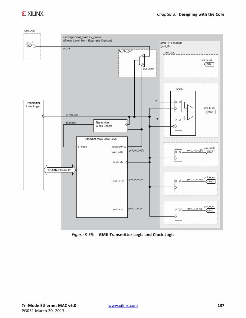
Tri-Mode Ethernet MAC v6.0 www.xilinx.com 137PG051 March 20, 2013
Chapter 3: Designing with the Core
X-Ref Target - Figure 3-59
Figure 3-59: GMII Transmitter Logic and Clock Logic

Tri-Mode Ethernet MAC v6.0 www.xilinx.com 138PG051 March 20, 2013
Chapter 3: Designing with the Core
GMII Receive Interface
In this implementation, a BUFIO is used to provide the lowest form of clock routing delay from input clock to input GMII RX signal sampling at the device IOBs. However, this creates placement constraints; a BUFIO capable clock input pin must be selected, and all other input GMII RX signals must be placed in the respective BUFIO region. The 7 Series Clocking Resources User Guide (UG472) [Ref 4] should be consulted.
The input clock is also placed onto regional clock routing using the BUFR component as illustrated in Figure 3-60. This regional clock then provides the clock for all receiver logic, both within the core and for the user-side logic which connects to the receiver AXI4-Stream interface of the core.
The IODELAY elements can be adjusted to f ine-tune the setup and hold times at the GMII IOB input flip-flops. This meets input setup and hold constraints at all three Ethernet speeds. The delay is applied to the IODELAY element using constraints in the XDC; these can be edited if desired. See Chapter 5, Constraining the Core.
Closely linked to the clock logic is the use of the rx_enable clock enable derivation. This must be provided to the Ethernet MAC core level. All user logic uses the AXI4-Stream interface handshaking to throttle the data to allow for the differing data widths between the 4-bit MII and the core 8-bit user datapath.

Tri-Mode Ethernet MAC v6.0 www.xilinx.com 139PG051 March 20, 2013
Chapter 3: Designing with the Core
Multiple Core Instantiations
Note: Because both mii_tx_clk and gmii_rx_clk are sourced by the external PHY device connected to the GMII/MII, it is not possible to share global transmitter or receiver clock resources across multiple instantiations of the core. Each instance of the core requires its own endpoint clocking resources. RGMII provides a more optimal solution because it does allow transmitter clock resources to be shared. See Reduced Gigabit Media Independent Interface (RGMII).
Figure 3-61 illustrates multiple instances of the core in 7 series devices. The 1 Gb/s transmitter reference clock source, gtx_clk , can be shared across all cores as illustrated in Figure 3-61. However, global transmitter and receiver clock resources cannot be shared and require independent BUFGMUX/BUFR elements as shown.
Figure 3-61 illustrates only two cores. However, more can be added using the same principal. This is done by instantiating the cores using the block level (from the example design) and sharing the gtx_clk clock source across all instantiations.
X-Ref Target - Figure 3-60
Figure 3-60: GMII Receiver Logic and Clock Logic for 7 Series Devices
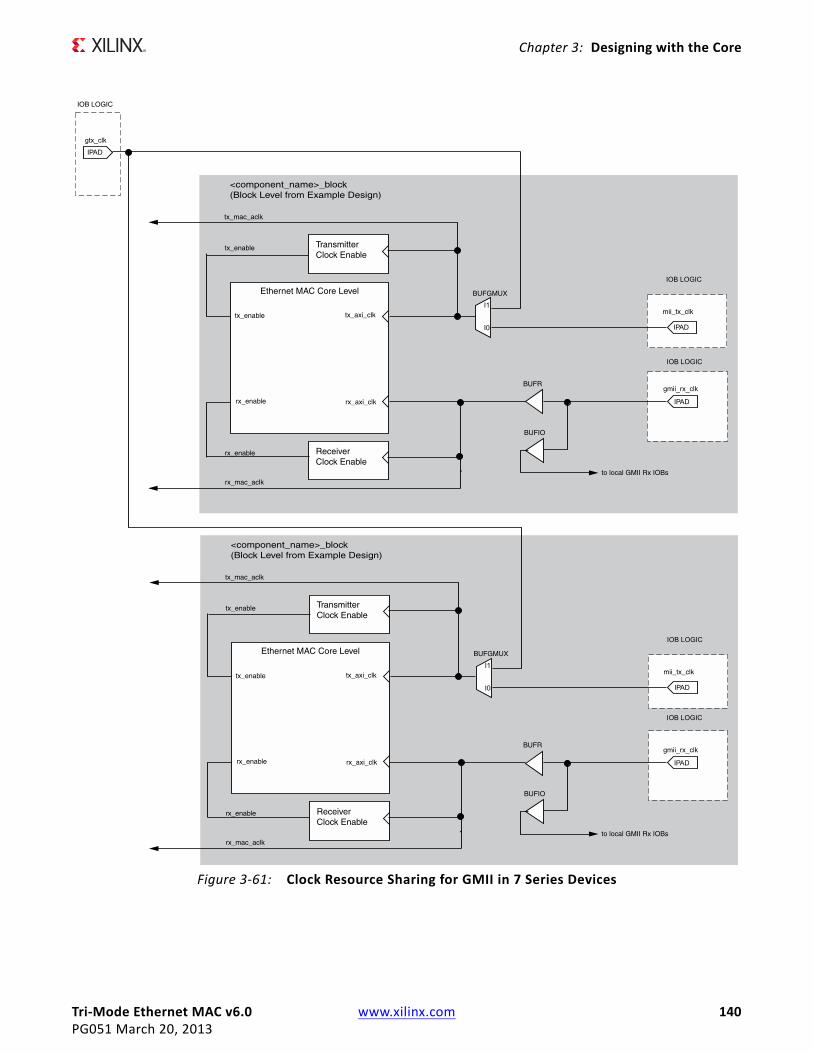
Tri-Mode Ethernet MAC v6.0 www.xilinx.com 140PG051 March 20, 2013
Chapter 3: Designing with the Core
X-Ref Target - Figure 3-61
Figure 3-61: Clock Resource Sharing for GMII in 7 Series Devices

Tri-Mode Ethernet MAC v6.0 www.xilinx.com 141PG051 March 20, 2013
Chapter 3: Designing with the Core
Reduced Gigabit Media Independent Interface (RGMII)The logic required to implement the RGMII transmitter logic is illustrated in Figure 3-62. The gtx_clk is a user-supplied 125 MHz reference clock source which is placed onto global clock routing to provide the clock for all transmitter logic, both within the core and for the user-side logic which connects to the transmitter AXI4-Stream interface of the TEMAC.
For RGMII, this global 125 MHz is used to clock transmitter logic at all three Ethernet speeds. The data rate difference between the three speeds is compensated for by the transmitter clock enable logic (the enable_gen module from the example design describes the required logic). The derived tx_enable signal must be supplied to the Ethernet MAC core level. All user logic uses the AXI4-Stream interfaces built in handshaking to throttle the data appropriately, under control of the Ethernet MAC core level. At all speeds the MAC expects the user logic to supply/accept new data after each validated clock cycle. The generated tx_enable signal is always high at 1 Gb/s, high for one in ten cycles at 100 Mb/s and high for one in a hundred cycles at 10 Mb/s. The advantage of this approach is that it allows common transmitter global clocks to be shared across any number of instantiated cores.
Figure 3-62 illustrates how to use the physical transmitter interface of the core to create an external RGMII. The signal names and logic shown in this f igure exactly match those delivered with the example design. Figure 3-62 shows that the output transmitter signals are registered in device IOBs, using DDR registers, before driving them to the device pads.
The logic required to forward the transmitter clock is also shown. This logic uses an IOB output Double-Data-Rate (DDR) register so that the clock signal produced incurs exactly the same delay as the data and control signals. However, the clock signal is then routed though an output delay element (IODELAY) before connecting to the device pad. The result of this is to create a 2 ns delay, which places the rgmii_txc forwarded clock in the center of the data valid window for forwarded RGMII data and control signals when operating at 1 Gb/s Ethernet speed. At 10 Mb/s and 100 Mb/s speeds, the enable_gen module toggles the DDR input signals at the required frequency so that the forwarded rgmii_txc clock is always of the correct frequency for the forwarded data.

Tri-Mode Ethernet MAC v6.0 www.xilinx.com 142PG051 March 20, 2013
Chapter 3: Designing with the Core
HR I/O do not include ODELAY components and another method is required to introduce the required 2 ns offset between the clock and data. The logic required to implement the RGMII transmitter logic is illustrated in Figure 3-63. The gtx_clk and gtx_clk90 signals are user-supplied 125 MHz reference clock sources with gtx_clk90 having a 90o phase shift with respect to gtx_clk . These are placed onto global clock routing to provide the clocks for all transmitter logic. The gtx_clk is used for the RGMII data and control and is also the clock source for the transmit datapath of the core. The gtx_clk90 is used for the RGMII clock only.
For RGMII, this global 125 MHz is used to clock transmitter logic at all three Ethernet speeds. The data rate difference between the three speeds is compensated for by the transmitter clock enable logic (the enable_gen module from the example design
X-Ref Target - Figure 3-62
Figure 3-62: RGMII Transmitter Logic and Clock Logic for 7 Series Devices

Tri-Mode Ethernet MAC v6.0 www.xilinx.com 143PG051 March 20, 2013
Chapter 3: Designing with the Core
describes the required logic). The derived tx_enable signal must be supplied to the Ethernet MAC core level. All user logic uses the AXI4-Stream interfaces built in handshaking to throttle the data appropriately, under control of the Ethernet MAC core level. At all speeds the MAC expects the user logic to supply/accept new data after each validated clock cycle. The generated tx_enable signal is always high at 1 Gb/s, high for one in ten cycles at 100 Mb/s and high for one in a hundred cycles at 10 Mb/s. The advantage of this approach is that it allows common transmitter global clocks to be shared across any number of instantiated cores.
Figure 3-63 illustrates how to use the physical transmitter interface of the core to create an external RGMII. The signal names and logic shown in this f igure exactly match those delivered with the example design. Figure 3-63 shows that the output transmitter signals are registered in device IOBs, using DDR registers, before driving them to the device pads.
The logic required to forward the transmitter clock is also shown. This logic uses an IOB output Double-Data-Rate (DDR) register so that the clock signal produced incurs exactly the same delay as the data and control signals. However, the clock signal uses the 90o phase shifted version of the clock. The result of this is to create a 2 ns delay, which places the rgmii_txc forwarded clock in the center of the data valid window for forwarded RGMII data and control signals when operating at 1 Gb/s Ethernet speed. At 10 Mb/s and 100 Mb/s speeds, the enable_gen module toggles the DDR input signals at the required frequency so that the forwarded rgmii_txc clock is always of the correct frequency for the forwarded data.
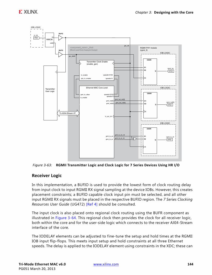
Tri-Mode Ethernet MAC v6.0 www.xilinx.com 144PG051 March 20, 2013
Chapter 3: Designing with the Core
Receiver Logic
In this implementation, a BUFIO is used to provide the lowest form of clock routing delay from input clock to input RGMII RX signal sampling at the device IOBs. However, this creates placement constraints; a BUFIO capable clock input pin must be selected, and all other input RGMII RX signals must be placed in the respective BUFIO region. The 7 Series Clocking Resources User Guide (UG472) [Ref 4] should be consulted.
The input clock is also placed onto regional clock routing using the BUFR component as illustrated in Figure 3-64. This regional clock then provides the clock for all receiver logic, both within the core and for the user-side logic which connects to the receiver AXI4-Stream interface of the core.
The IODELAY elements can be adjusted to fine-tune the setup and hold times at the RGMII IOB input flip-flops. This meets input setup and hold constraints at all three Ethernet speeds. The delay is applied to the IODELAY element using constraints in the XDC; these can
X-Ref Target - Figure 3-63
Figure 3-63: RGMII Transmitter Logic and Clock Logic for 7 Series Devices Using HR I/O

Tri-Mode Ethernet MAC v6.0 www.xilinx.com 145PG051 March 20, 2013
Chapter 3: Designing with the Core
be edited if desired. See Constraining the Core in Chapter 5.
Closely linked to the clock logic is the use of the rx_enable clock enable derivation. This must be provided to the Ethernet MAC core level. All user logic uses the AXI4-Stream interface handshaking to throttle the data as required at the different speeds.
Clock Resource Sharing
Figure 3-65 illustrates clock resource sharing across multiple instantiations of the core when using RGMII in 7 series devices using HP I/O. Figure 3-66 illustrates clock resource sharing across multiple instantiations of the core when using RGMII in 7 series devices using HR I/O. For all instantiations, gtx_clk and gtx_clk90, where present, can be shared between multiple cores, resulting in a common clock domain across the device. The receiver clocks cannot be shared. Each core is provided with its own local version of rgmii_rxc from the connected external PHY device as shown.
Figure 3-65 and Figure 3-66 show only two cores. However, more can be added using the same principal. This is done by instantiating the cores using the block level (from the
X-Ref Target - Figure 3-64
Figure 3-64: RGMII Receiver Logic and Clock Logic for 7 Series Devices

Tri-Mode Ethernet MAC v6.0 www.xilinx.com 146PG051 March 20, 2013
Chapter 3: Designing with the Core
example design) and sharing gtx_clk and gtx_clk90, if required, across all instantiations. The receiver clock, which cannot be shared, is unique for every instance of the core.
X-Ref Target - Figure 3-65
Figure 3-65: Clock Resource Sharing for RGMII in 7 Series Using HP I/O
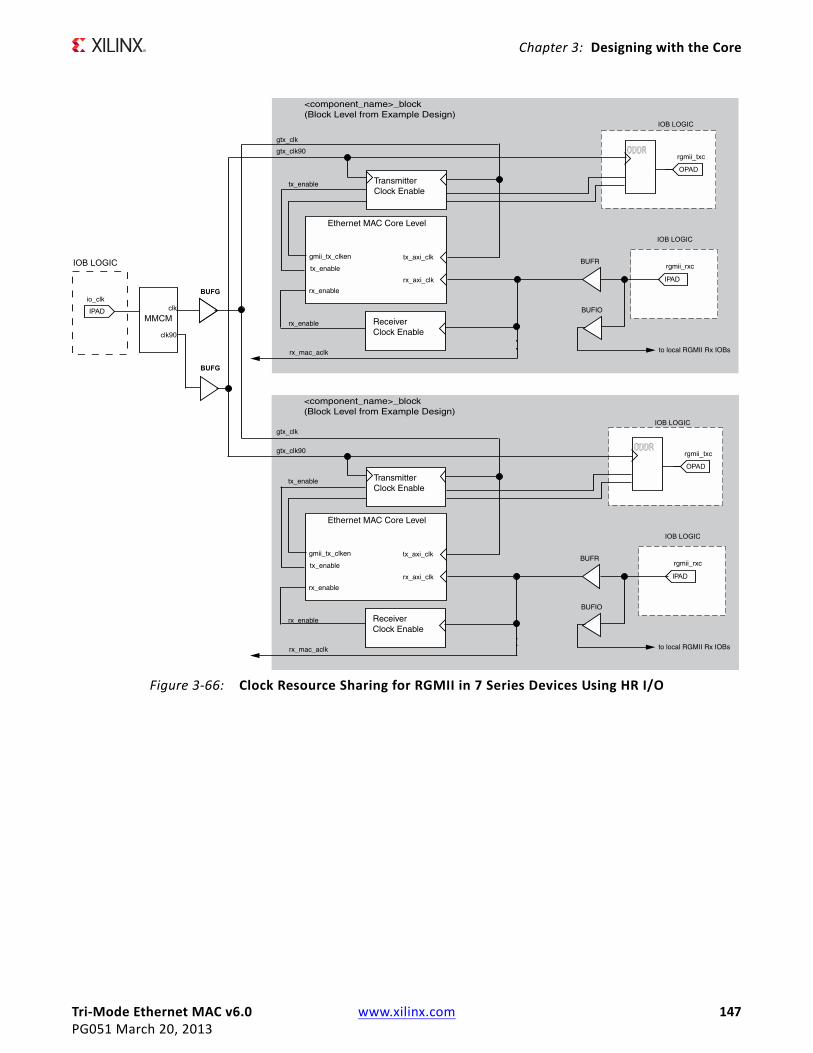
Tri-Mode Ethernet MAC v6.0 www.xilinx.com 147PG051 March 20, 2013
Chapter 3: Designing with the Core
X-Ref Target - Figure 3-66
Figure 3-66: Clock Resource Sharing for RGMII in 7 Series Devices Using HR I/O

Tri-Mode Ethernet MAC v6.0 www.xilinx.com 148PG051 March 20, 2013
Chapter 3: Designing with the Core
Interfacing to Other Xilinx Ethernet Cores
Ethernet 1000BASE-X PCS/PMA or SGMII CoreThe Ethernet MAC core can be integrated in a single device with the Ethernet 1000BASE-X PCS/PMA or SGMII core to provide either:
• A MAC with an SGMII interface to an external PHY device. SGMII can support either tri-speed (10/100/1000 Mb/s) designs or 1 Gb/s only designs.
• A 1 Gb/s Ethernet MAC core with 1000BASE-X PCS/PMA sublayer functionality: this is a 1 Gb/s only PHY standard which is most commonly used for a f iber optic medium.
For more details on the Xilinx Ethernet 1000BASE-X PCS/PMA or SGMII core, see the product page at:
www.xilinx.com/products/intellectual-property/DO-DI-GMIITO1GBSXPCS.htm
The Ethernet 1000BASE-X PCS/PMA or SGMII Product Guide [Ref 1] provides the information required to connect the two cores together in any supported configuration.
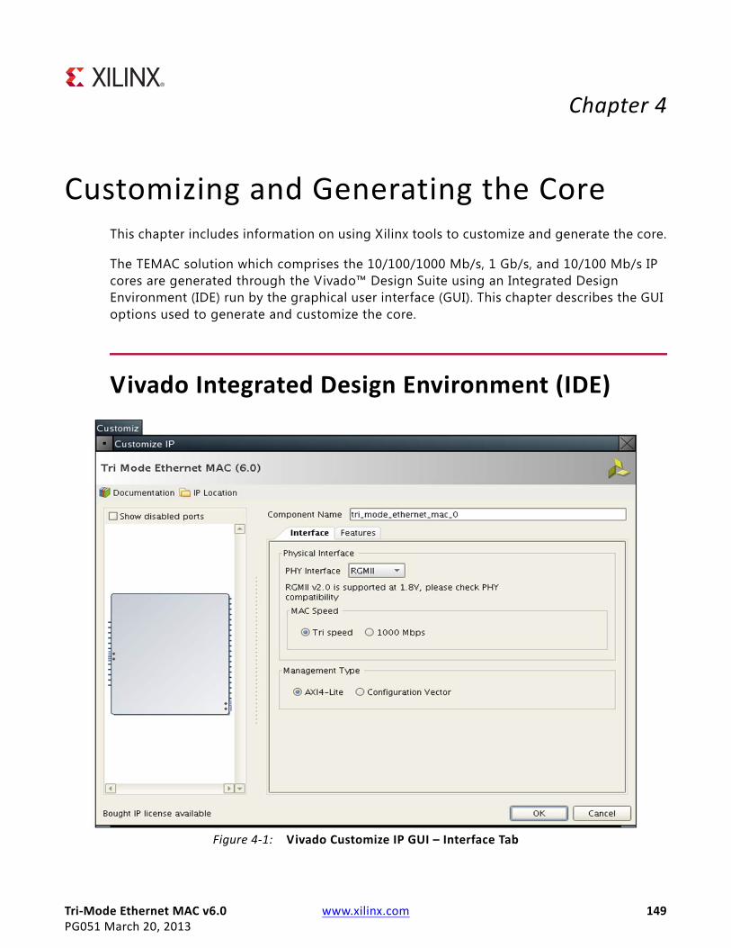
Tri-Mode Ethernet MAC v6.0 www.xilinx.com 149PG051 March 20, 2013
Chapter 4
Customizing and Generating the CoreThis chapter includes information on using Xilinx tools to customize and generate the core.
The TEMAC solution which comprises the 10/100/1000 Mb/s, 1 Gb/s, and 10/100 Mb/s IP cores are generated through the Vivado™ Design Suite using an Integrated Design Environment (IDE) run by the graphical user interface (GUI). This chapter describes the GUI options used to generate and customize the core.
Vivado Integrated Design Environment (IDE)X-Ref Target - Figure 4-1
Figure 4-1: Vivado Customize IP GUI – Interface Tab

Tri-Mode Ethernet MAC v6.0 www.xilinx.com 150PG051 March 20, 2013
Chapter 4: Customizing and Generating the Core
Component NameThe component name is used as the base name of the output f iles generated for the core. Names must begin with a letter and must be composed from the following characters: a through z, 0 through 9 and “_”.
These features are included in the Interface tab of the Vivado Customize IP GUI (Figure 4-1).
Physical InterfaceFour physical interface types are available for the core:
• GMII. The Gigabit Media Independent Interface (GMII) is defined by the IEEE802.3 specification; it can provide support for Ethernet operation at 10 Mb/s, 100 Mb/s, and 1 Gb/s speeds.
• MII. The Media Independent Interface (MII) is defined by the IEEE802.3 specif ication; it can provide support for Ethernet operation at 10 Mb/s and 100 Mb/s speeds.
• RGMII. The Reduced Gigabit Media Independent Interface (RGMII) is, effectively, a Double Data Rate version of GMII; it can provide support for Ethernet operation at 10 Mb/s, 100 Mb/s, and 1 Gb/s speeds.
• Internal. The core is generated with no physical interface ready for connection to an internal PHY such as the Ethernet 1000BASE-X PCS/PMA or SGMII LogiCORE.
The choice of physical interface determines the content of the example design delivered with the core where the external GMII, MII or RGMII is described in HDL. There is no change in the core HDL between RGMII, GMII or Internal. If MII is selected then the physical interface datapath is reduced to four bits. The default is to use GMII.
MAC SpeedThe TEMAC solution can provide support for 1 Gb/s speed only operation; 10 Mb/s and 100 Mb/s speed operation; full tri-speed operation (10 Mb/s, 100 Mb/s, and 1 Gb/s speed capability).
The available choice for speed support selection is dependent on the chosen Physical Interface:
• If GMII or RGMII is selected, then Tri-speed operation and 1 Gb/s only operation are available for selection.
• If MII is selected, then only 10 Mb/s and 100 Mb/s operation is available.
• If Internal is selected then only Tri-speed is available as the speed is under the control of the internal PHY.

Tri-Mode Ethernet MAC v6.0 www.xilinx.com 151PG051 March 20, 2013
Chapter 4: Customizing and Generating the Core
Management TypeSelect the AXI4-Lite option if you wish to include the optional Management Interface for TEMAC configuration (see Management Interface). If this option is not selected, the core is generated with a replacement configuration vector. If the AXI4-Lite Management Interface is not selected the AVB option is not available. The default is to have the AXI4-Lite Management Interface.
These features are included in the Features tab of the Vivado Customize IP GUI (Figure 4-2).
MAC OptionsThe TEMAC solution always provides support for full-duplex Ethernet. However, to provide half-duplex operation, further FPGA logic resources are required. Because many applications require only full-duplex support, the half-duplex logic is therefore optional.
When the core is generated with half-duplex logic, full- or half-duplex operation can be selected using TEMAC configuration.
The default is to include half-duplex support.
X-Ref Target - Figure 4-2
Figure 4-2: Vivado Customize IP GUI – Features Tab

Tri-Mode Ethernet MAC v6.0 www.xilinx.com 152PG051 March 20, 2013
Chapter 4: Customizing and Generating the Core
When half-duplex is selected the AVB option is disabled.
Note: If a MMCM is used on the physical interface receive path to control the clock to data relationship then 1 G half-duplex is not supported.
AVB OptionSelect the Enable_AVB option if you wish the optional AVB Endpoint front end logic to be included.
• If half-duplex is selected the AVB option is disabled
• If the AXI4-Lite management interface is not selected the AVB option is disabled
If selected, the fee-based Ethernet AVB Endpoint license is required in addition to the Tri-Mode Ethernet MAC license to enable core generation. The default is to not have the AVB Endpoint included.
Frame Filter OptionsIt is possible to generate the core with a frame filter, which prevents the reception of frames that are not matched by this MAC. This is most commonly used to identify packets which are addressed specif ically to this MAC. The default is to use the frame filter.
Number of Table EntriesThe frame filter can be generated with a look-up table that holds up to eight additional valid MAC frame match patterns. You can select an integer between 0 and 8 to define the number of match patterns that are present in the table. The default is to use 4 table entries.
Statistics CountersIt is possible to generate the core with built in statistics counters. The number of counters available is dependent upon the duplex setting of the core with full-duplex requiring 34 counters and half-duplex requiring 44 counters. This option can only be selected when the core is configured with the AXI4-Lite Management Interface. The default is to include the Statistics counters
Statistics WidthThe Statistics counters can be either 32 bits or 64 bits wide. This allows you to control the frequency at which the counters must be polled to avoid information loss due to overflow. The default is to use 64-bit wide counters.
Tri-Mode Ethernet MAC v6.0 www.xilinx.com 153PG051 March 20, 2013
Chapter 4: Customizing and Generating the Core
Statistics ResetWhen the Statistics Counters are included it is possible to include logic to ensure the counters are cleared to zero upon a hardware reset. Without this logic the counter values persist over a reset and are only cleared upon device configuration. The default is to include the counter reset functionality
Output GenerationThe TEMAC solution delivers files into several f ilegroups. By default the f ilegroups necessary for use of the TEMAC or opening the IP Example design are generated when the core is generated. If additional f ilegroups are required these can be selected using the generate option.
The filegroups generated can be seen in the IP Sources tab of the Sources window where they are listed for each IP in the project.
The filegroups available for the TEMAC solution are:
ExamplesIncludes all source required to be able to open and implement the IP example design project. That is, example design HDL and the example design xdc f ile.
Examples SimulationIncludes all source required to be able to simulate the IP example design project. This is the same list of HDL as the Examples f ilegroup with the addition of the demonstration test bench HDL.
SynthesisIncludes all synthesis sources required by the core. For the TEMAC solution this is a mix of both encrypted and unencrypted source. Only the unencrypted sources are visible.
SimulationIncludes all simulation sources required by the core. Simulation of the TEMAC solution at the core level is not supported without the addition of a test bench (not supplied). Simulation of the example design is supported.
Tri-Mode Ethernet MAC v6.0 www.xilinx.com 154PG051 March 20, 2013
Chapter 5
Constraining the Core
Required ConstraintsThis chapter defines the constraint requirements of the TEMAC solution. The TEMAC solution is provided with a core level XDC file. This provides constraints for the core which are expected to be applied in all instantiations of the core. This XDC file, named <component name>.xdc, can be found in the IP Sources tab of the Sources window in the Synthesis f ile group.
An example XDC is also provided with the HDL example design to provide the board level constraints. This is specific to the example design and, as such, is only expected to be used as a template for the user design. See Chapter 6, Example Design. This XDC file, named <component name>_example_design.xdc, is found in the IP Sources tab of the Sources window in the Examples file group.
The core level XDC file inherits some constraints from the example design XDC file. In any system it is expected that you would also provide an XDC file to constrain the logic in which the TEMAC solution is instantiated.
Device, Package, and Speed Grade SelectionsThe core can be implemented in Virtex®-7, Kintex™-7, and Artix™-7 devices with these attributes:
• Large enough to accommodate the core
• Contains a suff icient number of IOBs
• Device has a supported speed grade:
Table 5-1: Supported Speed Grades
Device Family Speed Grade
Virtex-7 -1 or faster
Kintex-7 -1 or faster
Artix-7 -1 or faster

Tri-Mode Ethernet MAC v6.0 www.xilinx.com 155PG051 March 20, 2013
Chapter 5: Constraining the Core
Clock FrequenciesThe TEMAC solution has a variable number of clocks with the precise number required being dependent upon the specif ic parameterization.
As the core targets a specific interface standard (RGMII/GMII or MII) there are associated clock frequency requirements.
I/O Standard and PlacementOf the various interfaces provided when the TEMAC solution is generated only the interface to the selected PHY is expected to be propagated to actual device I/O. As such there are no specific I/O standard/placement requirements on most interfaces. When the TEMAC is generated with either RGMII/GMII or MII support, the related interfaces and the MDIO interface, if present, are expected to propagate to device I/O and as such there are some limitations which have to be considered.
Depending upon the device family, part and package chosen there are two types of I/O available for use. HP I/O is intended for support of high speed interfaces and as such is limited to 1.8V support. HP I/O supports both Input and Output Delays components. HR I/O is intended for interfaces with higher voltage requirements and has a more limited supported frequency range. HR I/O only supports Input Delay components.
Both MII and GMII are 3.3V standards, with RGMII being a 1.8V standard. However the majority of PHYs are multi-standard and operate at either 2.5V or 3.3V and this is also true of the PHYs selected for Xilinx development boards. This means that for most applications the physical interfaces are restricted to either using HR I/O, where available, or HP I/O with an external voltage converter to translate between 1.8V and the minimum level required by
Table 5-2: TEMAC Solution Frequency Requirements
Clock Name Parameterization Frequency Requirement
gtx_clk Always present 125 MHz
gtx_clk90 RGMII when HRIO used for interface. 90 degree shifted version of gtx_clk 125 MHz
refclk RGMII or GMII. Required for the idelayctrl. 200-300 MHz
mii_tx_clk GMII or MII. Required for 10/100 Mb/s operation 25 MHz
mii_rx_clk MII. 25 MHz
gmii_rx_clk GMII. 125 MHz
rgmii_rxc RGMII 125 MHz
s_axi_aclk Management Type set to AXI4-Lite 10-300 MHz

Tri-Mode Ethernet MAC v6.0 www.xilinx.com 156PG051 March 20, 2013
Chapter 5: Constraining the Core
the PHY of 2.5V. For any board design it is important to identify which type of I/O is available/being used.
For the 1 Gb/s interface standards (RGMII and GMII), the receive data interface from the PHY can have some placement requirements, depending upon the capture interface used. Across all supported families there are two common capture methods used, these are detailed in Physical Interfaces for 1 Gb/s Only Ethernet MAC IP Core in Chapter 3 and Physical Interfaces for Tri-Speed (10 Mb/s, 100 Mb/s, and 1 Gb/s) Ethernet MAC IP Core in Chapter 3. In summary, the receive data sample window is adjusted by either shifting the data using Input delays or by shifting the clock using a PLL/MMCM. When the Data is shifted a BUFIO is used to provide the lowest form of clock routing delay from input clock to input RX signal sampling at the device IOBs. However, this creates placement constraints; a BUFIO capable clock input pin must be selected, and all other input RGMII/GMII RX signals must be placed in the respective BUFIO region. The relevant family User Guide should be consulted. This requirement does not exist if the PLL/MMCM method is used.

Tri-Mode Ethernet MAC v6.0 www.xilinx.com 157PG051 March 20, 2013
Chapter 6
Example DesignThis section provides detailed information about the example design, including a description of the f ile groups, the contents of the example HDL wrappers, and the operation of the demonstration test bench.
The example design, under certain core configurations, is intended to directly target key Xilinx Demonstration Platforms. The current supported boards are the Kintex™-7 (KC705 Board) and Artix™-7 (AC701 Board) FPGAs.
The example design includes a basic state machine which, through the AXI4-Lite interface, brings up the external PHY and MAC to allow basic frame transfer.
A Simple Frame Generator and Frame Checker are also included which can be used to turn a particular board into a packet generator with any received data optionally being checked. If the TEMAC is generated with the Optional AVB Endpoint another frame generator and frame checker are included to exercise the additional AV datapath.
Loopback functionality is provided as either MAC RX to TX loopback, where the loopback logic becomes the packet source in place of the packet generator, or PHY TX to RX loopback, with the loopback replacing the demonstration test bench stimulus and checker. Basic control of the state machine, allowing MAC speed change is achieved using push buttons and DIP switches on the board. See the board specif ic sections in Targeting the Example Design to a Board, page 169
top directory link - white text invisible

Tri-Mode Ethernet MAC v6.0 www.xilinx.com 158PG051 March 20, 2013
Chapter 6: Example Design
Detailed Example DesignFigure 6-1 illustrates the top-level design for the TEMAC solution example design.
The HDL example design contains the following:
• An instance of the TEMAC solution
• Clock management logic, including MMCM and Global Clock Buffer instances, where required
• MII, GMII or RGMII interface logic, including IOB and DDR registers instances, where required
• Statistics vector decode logic
• AXI4-Lite to IPIF interface logic
• User Transmit and Receive FIFOs with AXI4-Stream interfaces
• User basic pattern generator module that contains a frame generator and frame checker plus loopback logic.
• User AVB pattern generator module providing a second frame generator and frame checker for designs including the AVB Endpoint.
• A simple state machine to bring up the PHY (if any) and MAC ready for frame transfer
X-Ref Target - Figure 6-1
Figure 6-1: HDL Example Design
<component_name>_block
<component_name>_example_design
Pattern Generator& Checker
Physical Interface
<component_name>_fifo_block
Statistics Vectors Interface
ClockGeneration
MII/GMII/RGMIIInterfaceLogic and
Clocks
TEMAC Core&
AVB Endpoint
Tx FIFO
Rx FIFO
10 Mbps, 100 Mbps,1 Gbps Ethernet FIFO
InterfaceMDIO
StatisticsVector Decode
AXI4-Liteto IPIF
AXI4-LiteControlState
Machine
AVB Pattern
Generator& Checker
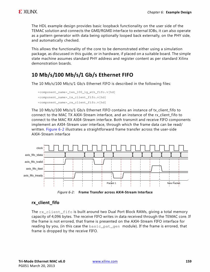
Tri-Mode Ethernet MAC v6.0 www.xilinx.com 159PG051 March 20, 2013
Chapter 6: Example Design
The HDL example design provides basic loopback functionality on the user side of the TEMAC solution and connects the GMII/RGMII interface to external IOBs, it can also operate as a pattern generator with data being optionally looped back externally, on the PHY side, and automatically checked.
This allows the functionality of the core to be demonstrated either using a simulation package, as discussed in this guide, or in hardware, if placed on a suitable board. The simple state machine assumes standard PHY address and register content as per standard Xilinx demonstration boards.
10 Mb/s/100 Mb/s/1 Gb/s Ethernet FIFOThe 10 Mb/s/100 Mb/s/1 Gb/s Ethernet FIFO is described in the following f iles:
<component_name>_ten_100_1g_eth_fifo.v[hd]
<component_name>_tx_client_fifo.v[hd]
<component_name>_rx_client_fifo.v[hd]
The 10 Mb/s/100 Mb/s/1 Gb/s Ethernet FIFO contains an instance of tx_client_f ifo to connect to the MAC TX AXI4-Stream interface, and an instance of the rx_client_f ifo to connect to the MAC RX AXI4-Stream interface. Both transmit and receive FIFO components implement an AXI4-Stream user interface, through which the frame data can be read/written. Figure 6-2 illustrates a straightforward frame transfer across the user-side AXI4-Stream interface
rx_client_fifo
The rx_client_fifo is built around two Dual Port Block RAMs, giving a total memory capacity of 4,096 bytes. The receive FIFO writes in data received through the TEMAC core. If the frame is not errored, that frame is presented on the AXI4-Stream FIFO interface for reading by you, (in this case the basic_pat_gen module). If the frame is errored, that frame is dropped by the receive FIFO.
X-Ref Target - Figure 6-2
Figure 6-2: Frame Transfer across AXI4-Stream Interface
clock
axis_fifo_tdata
axis_fifo_tvalid
axis_fifo_tlast
axis_fifo_tready
Packet 1 New Packet.

Tri-Mode Ethernet MAC v6.0 www.xilinx.com 160PG051 March 20, 2013
Chapter 6: Example Design
If the receive FIFO memory overflows, the frame currently being received is dropped, regardless of whether it is a good or bad frame, and the signal rx_overflow is asserted. Situations in which the memory can overflow are:
• The FIFO can overflow if the receiver clock is running at a faster rate than the transmitter clock or if the inter-packet gap between the received frames is smaller than the interpacket gap between the transmitted frames. If this is the case, the TX FIFO is not able to read data from the RX FIFO as fast as it is being received.
• The FIFO size of 4,096 bytes limits the size of the frames that it can store without error. If a frame is larger than 4,000 bytes, the FIFO can overflow and data is then lost. It is therefore recommended that the example design is not used with the TEMAC solution in jumbo frame mode for frames of larger than 4,000 bytes.
tx_client_fifo
The tx_client_fifo is built around two Dual Port Block RAMs, giving a total memory capacity of 4096 bytes.
When a full frame has been written into the transmit FIFO, the FIFO presents data to the MAC transmitter. The MAC uses tx_axis_mac_tready to throttle the data until it has control of the medium.
If the FIFO memory f ills up, the tx_axis_fifo_tready signal is used to halt the AXI4-Stream interface writing in data, until space becomes available in the FIFO. If the FIFO memory f ills up but no full frames are available for transmission. For example, if a frame larger than 4,000 bytes is written into the FIFO, the FIFO asserts the tx_overflow signal and continues to accept the rest of the frame from you. The overflow frame is dropped by the FIFO. This ensures that the AXI4-Stream FIFO interface does not lock up.
Basic Pattern Generator ModuleThe Basic Pattern Generator is described in the following f iles:
<component_name>_basic_pat_gen.v[hd]
<component_name>_axi_pat_gen.v[hd]
<component_name>_axi_pat_check.v[hd]
<component_name>_axi_mux.v[hd]
<component_name>_axi_pipe.v[hd]
<component_name>_address_swap.v[hd]
The basic pattern generator has two main functional modes: loopback and generator. In loopback the data from the RX FIFO is passed to the address swap module and passed from there to the TX FIFO. In Generator mode the TX data is provided by the Pattern Generator, with RX Data being optionally checked by the pattern Checker.

Tri-Mode Ethernet MAC v6.0 www.xilinx.com 161PG051 March 20, 2013
Chapter 6: Example Design
Address Swap
The address swap module can be enabled for use on the loopback path. This would allow the example design, targeted to a suitable board, to be connected to an Ethernet protocol tester. The address swap module waits until both the DA and SA have been received before starting to send data on to the TX FIFO.
If enabled, the module swaps the destination and source addresses of each frame as shown in Figure 6-3 to ensure that the outgoing frame destination address matches the source address of the link partner, otherwise the DA and SA are left untouched. The module transmits the frame control signals with an equal latency to the frame data
Pattern Generator
This pattern generator can be enabled/disabled using a DIP switch. when Enabled the data from the RX FIFO is flushed and the axi_pat_gen module drives the address_swap modules inputs.
The pattern generator allows user modification of the Destination Address, Source Address, minimum frame size and maximum frame size using parameters. When enabled, using a dedicated input mapped to a DIP switch on a board, it starts with the minimum frame size and after each frame is sent, increments the frame size until the maximum value is reached, it then starts again at the minimum frame size.
In all cases the Destination and Source address are as provided by HDL parameters, with the Type/Length f ield being dependent upon the frame size and the frame data being a decrementing count starting from the value in the type/length f ield. This should mean that the final data byte in all frames is 0x1. This is shown in Figure 6-4.
X-Ref Target - Figure 6-3
Figure 6-3: Modification of Frame Data by Address Swap Module

Tri-Mode Ethernet MAC v6.0 www.xilinx.com 162PG051 March 20, 2013
Chapter 6: Example Design
In a loopback scenario (using a second board as the loopback), the ppm difference between the oscillators on the two boards can cause overflows in the slower board—resulting in errors. This is normally observed when the slower board is operating as the loopback board. To avoid this issue the data rate provided by the pattern generator is throttled to just below the selected line rate.
Pattern Checker
The axi_pat_check module provides a simple sanity check that data is being received correctly. It uses the same parameters as the axi_pat_gen module and therefore expects the same frame contents and frame size increments. Because the Frame data can or cannot have the DA and SA swapped the pattern checker allows either value to be in either location.
When enabled, using a dedicated input which uses a board DIP switch, the output from the RX_FIFO is monitored. The first step is to identify where in the frame sequence the data is, this is done by capturing the value in the type/length field. After this is done the following frame is expected to be incrementally bigger (unless you happen to be at the wrap point). If an error is detected an error is raised on the byte or bytes which mismatch and the error condition is latched and output to a dedicated output; this is displayed using a board LED. The pattern checker state machine then re-synchronizes to the data. A dedicated input, connected to one of the push buttons, is used to clear this latched error state, enabling a feel for the frequency of errors (if any).
The pattern checker also provides a simple activity monitor. This toggles a dedicated output, which flashes a board LED, to indicate that RX Data is being received correctly. This ensures that the lack of a detected error is not just due to all frames being dropped.
X-Ref Target - Figure 6-4
Figure 6-4: Pattern Generator Frame Structure
axi_tclk
tdata
tvalid
tlast
tuser
tready
DA[1] DA[2] DA[3] DA[4] DA[5] DA[6] SA[1] SA[2] SA[3] SA[4] SA[5] SA[6] N[1] N[0] N[0] N[0]-1 N[0]-2 2 1 DA[1]
Destination Address Source Address Length Decrementing Data IFG(12cycles)
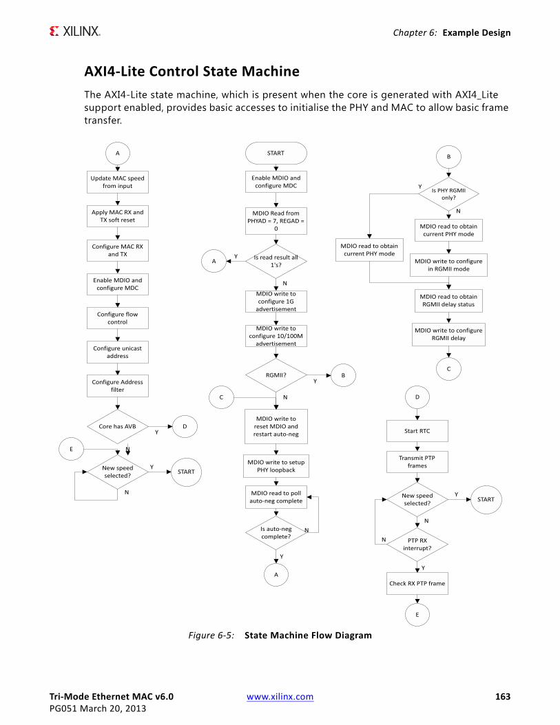
Tri-Mode Ethernet MAC v6.0 www.xilinx.com 163PG051 March 20, 2013
Chapter 6: Example Design
AXI4-Lite Control State MachineThe AXI4-Lite state machine, which is present when the core is generated with AXI4_Lite support enabled, provides basic accesses to initialise the PHY and MAC to allow basic frame transfer.
X-Ref Target - Figure 6-5
Figure 6-5: State Machine Flow Diagram

Tri-Mode Ethernet MAC v6.0 www.xilinx.com 164PG051 March 20, 2013
Chapter 6: Example Design
Figure 6-5 shows the accesses performed by the state machine. After a reset, and allowing settling time for internal resets to complete, the state machine f irst writes to the MAC to enable the MDIO and configure the MDIO clock (this assumes an s_axi_aclk running at 100 MHz). An MDIO read is then performed from PHYAD 7, which is the standard address used on Xilinx Demonstration Boards. If this returns all 1s it implies that no PHY exists at this location and further MDIO accesses are skipped.
This MDIO read enables the demonstration test bench to limit the number of MDIO accesses performed and reduce the run time of the simulations whilst still allowing the correct MDIO accesses to take place on a board. If the PHY is present, the MDIO read data has a value other than all 1s; the state machine then performs the necessary MDIO writes to configure the PHY speed advertisement as per the mac_speed inputs. If RGMII is selected, a read-modify-write is performed to select RGMII, unless the PHY is RGMII only, avoiding the need to change jumper settings on the board. Finally the PHY is reset and auto-negotiation restarted. After auto-negotiation completes the MAC speed is updated, as per the mac_speed inputs. The MAC is then configured to disable flow control, initialise the unicast address and set the Frame Filter to promiscuous mode. If the AVB Endpoint logic is present then the RTC is started and PTP frames both transmitted and received (this assumes an external loopback is in use). Finally the state machine sits and waits; if the update_speed input asserts it returns to the initial MDIO read state and the new mac_speed input is captured and applied.
With the state machine only applying a f ixed core configuration, logic can be stripped during logic optimization. To avoid this the state machine has a serial interface, serial_command and serial_response, which can be used to access any location and either perform a read or a write. This uncertainty prevents functions unused by the state machine from being stripped.

Tri-Mode Ethernet MAC v6.0 www.xilinx.com 165PG051 March 20, 2013
Chapter 6: Example Design
Demonstration Test Bench
Test Bench FunctionalityX-Ref Target - Figure 6-6
The demonstration test bench is defined in the following f iles:
demo_tb.v[hd]
The demonstration test bench is a simple VHDL or Verilog program to exercise the example design and the core itself. It has two modes of operation, DEMO and Built-in Self Test (BIST), with BIST being the default mode only when the AVB Endpoint is included. The mode can be changed using a parameter in the demonstration test bench code.
The test bench consists of the following:
• Clock generators
• DEMO – A stimulus block that connects to the GMII/MII or RGMII receiver interface of the example design
• DEMO – A monitor block to check data returned through the GMII/MII or RGMII transmitter interface
• BIST – A simple loopback from the GMII/MII or RGMII transmit interface to the receiver.
• BIST (AVB only) – A basic AV data bandwidth monitor.
Figure 6-6: Demonstration Test Bench
<component_name>_block
<component_name>_example_design
Pattern Generator& Checker
Physical Interface
<component_name>_fifo_block
Statistics Vectors Interface
ClockGeneration
MII/GMII/RGMIIInterfaceLogic and
Clocks
TEMAC Core&
AVB Endpoint&
Statistics
Tx FIFO
Rx FIFO
10 Mbps, 100 Mbps,1 Gbps Ethernet FIFO
Interface
MDIO
StatisticsVector Decode
AXI4-Liteto IPIF
AXI4-LiteControlState
Machine
demo_tb
MDIO Response
FrameMonitor
FrameStimulus
Test Control Stimulus
AVB Pattern
Generator& Checker

Tri-Mode Ethernet MAC v6.0 www.xilinx.com 166PG051 March 20, 2013
Chapter 6: Example Design
• A management block to control the speed selection
• An MDIO monitor/stimulus to check and respond to MDIO accesses, if a management interface is selected.
• A control mechanism to manage the interaction of management, stimulus and monitor blocks
Core with Management Interface
DEMO Mode
The demonstration test bench performs the following tasks:
• Input clock signals are generated.
• A reset is applied to the example design.
• The required speed is selected using mac_speed and update_speed
• The MDIO stimulus/response block responds to a read with all 1s - to indicate no PHY is present.
• Four frames are pushed into the GMII/MII or RGMII receiver interface at the fastest MAC speed supported:
° The first frame is a minimum length frame
° The second frame is a type frame
° The third frame is an errored frame
° The fourth frame is a padded frame
• The frames received at the GMII/MII or RGMII transmitter interface are checked against the stimulus frames to ensure data is the same. The monitor process takes into account the source/destination address f ield and FCS modifications resulting from the address swap module.
• If either the Tri-speed or MII configurations have been selected, mac_speed is updated to run at the next fastest available speed. This is 100 Mb/s or 10 Mb/s respectively. update_speed is then pulsed.
• The MDIO stimulus/response block responds to a read with all 1s - to indicate no PHY is present.
• The same four frames are then sent to the MII/GMII or RGMII interface and checked against the stimulus frames.
• If the Tri-speed configuration has been selected, mac_speed is updated to run at 10 Mb/s. update_speed is then pulsed.
• The MDIO stimulus/response block responds to a read with all 1s - to indicate no PHY is present.

Tri-Mode Ethernet MAC v6.0 www.xilinx.com 167PG051 March 20, 2013
Chapter 6: Example Design
• The same four frames are then sent to the MII/GMII or RGMII interface and checked against the stimulus frames.
• For the Tri-speed configuration, the speed is then changed back to 1 Gb/s and the same four frames are sent and checked for a final time. This tests the speed switching between 1 Gb/s and 10/100 Mb/s in both directions.
BIST Mode
The demonstration test bench performs the following tasks:
• Input clock signals are generated.
• A reset is applied to the example design.
• The required speed is selected using mac_speed and update_speed
• The MDIO stimulus/response block responds to a read with all 1s – to indicate no PHY is present.
• If the AVB Endpoint is included the AXI4-Lite state machine requests two TX PTP frames and checks they are received
• The pattern generator(s) and checker(s) are enabled
• The simulation runs for a fixed duration, allowing a large number of frames to pass.
• Any detected errors or lack of RX activity are reported as errors
• If the AVB Endpoint is included the bandwidth of the two data streams is reported.
Core with No Management Interface
DEMO Mode
The demonstration test bench performs the following tasks:
• Input clock signals are generated
• A reset is applied to the example design
• The required speed is selected using mac_speed and update_speed
• The stimulus block pushes four frames into the GMII/MII or RGMII receiver interface at the fastest speed supported by the selected configuration:
° The first frame is a minimum-length frame
° The second frame is a type frame
° The third frame is an errored frame
° The fourth frame is a padded frame

Tri-Mode Ethernet MAC v6.0 www.xilinx.com 168PG051 March 20, 2013
Chapter 6: Example Design
• The frames received at the GMII/MII or RGMII transmitter interface are checked against the stimulus frames to ensure data is the same. The monitor process takes into account the source/destination address f ield and FCS modifications resulting from the address swap module.
• If either the Tri-speed or MII configurations have been selected, mac_speed is updated to run at the next fastest available speed. This is 100 Mb/s or 10 Mb/s respectively. update_speed is then pulsed.
• The same four frames are then sent to the MII/GMII or RGMII interface and checked against the stimulus frames.
• If the Tri-speed configuration has been selected, mac_speed is updated to run at 10 Mb/s. update_speed is then pulsed. The same four frames are then sent to the MII or RGMII interface and checked against the stimulus frames.
• For the Tri-speed configuration, the speed is then changed back to 1 Gb/s and the same four frames are sent and checked for a final time. This tests the speed switching between 1 Gb/s and 10/100 Mb/s in both directions.
BIST Mode
The demonstration test bench performs the following tasks:
• Input clock signals are generated.
• A reset is applied to the example design.
• The required speed is selected using mac_speed and update_speed
• The pattern generator and checker are enabled
• The simulation runs for a fixed duration, allowing a large number of frames to pass.
• Any detected errors or lack of RX activity are reported as errors
Changing the Test BenchThe Demonstration test bench defaults to DEMO mode for all implementations which do not include the AVB Endpoint (which defaults to BIST mode).
The mode is set using a parameter in the demo_tb.v[hd] with the alternative mode being commented out. To change mode, uncomment the desired mode and either remove or comment the undesired one.
DEMO Mode
Changing Frame Data
The contents of the frame data passed into the TEMAC receiver can be changed by editing the DATA fields for each frame defined in the test bench. The test bench automatically
Tri-Mode Ethernet MAC v6.0 www.xilinx.com 169PG051 March 20, 2013
Chapter 6: Example Design
calculates the new FCS f ield to pass into the TEMAC, as well as calculating the new expected FCS value. Further frames can be added by defining a new frame of data.
Changing Frame Error Status
Errors can be inserted into any of the pre-defined frames by changing the error f ield to 1 in any column of that frame. When an error is introduced into a frame, the bad_frame f ield for that frame must be set to disable the monitor checking for that frame. The error currently written into the third frame can be removed by setting all error f ields for the frame to 0 and unsetting the bad_frame f ield.
BIST Mode
In BIST mode the data is provided by the Basic Pattern Generator Module. This allows a degree of control over the frames generated using the module parameters:
DEST_ADDR SRC_ADDR MAX_SIZE MIN_SIZE ENABLE_VLAN VLAN_ID VLAN_PRIORITY
The pattern generator does not have an error injection capability.
Targeting the Example Design to a BoardFor each supported device, there are certain TEMAC solution configurations which can be targeted directly to the Xilinx connectivity board for that device. The XDC included with the example design provides the required pin placements for the specif ic board. In each case the board DIP switches, push buttons, and LEDs are used to provide basic control over the MAC functionality. This is described in more detail in the board specific sections.
TEMAC Solution Configurations SupportedThere are some basic requirements for the example design to function correctly when targeted at a board. The TEMAC must:
• Include an AXI4-Lite Management interface
• Target the relevant part for the specific board – see the board specific section
Due to I/O limitations some connectivity boards use a RGMII only PHY. This is the case on the Artix-7 AC701. This means that the TEMAC must be configured for RGMII to be targeted to this board.
Tri-Mode Ethernet MAC v6.0 www.xilinx.com 170PG051 March 20, 2013
Chapter 6: Example Design
Bring Up SequenceWhen the example design is f irst targeted at a board, the following sequence is suggested to check if the various features are working. This is common for all boards.
1. Attach an Ethernet cable between the board and a PC installed with wireshark or similar.
2. Select the desired speed using the DIP switches.
3. Push the update speed pushbutton.
4. Ensure the link status LEDs show the expected speed.
5. Enable the pattern_generator using the DIP switch.
6. Capture and check the received frames at the PC and ensure they have the expected data pattern.
To utilize the pattern checker, check both datapaths. Two boards are required.
Board A: Operates as a frame source and optionally checker.
Board B: This board operates as a simple loopback board.
Bring up process:
1. Attach an Ethernet cable between the two boards.
2. Select the desired speed on both boards. This must be the same setting.
3. Push the update speed button on both boards.
4. Check the link status LEDs show the correct speed.
5. Enable the pattern generator on Board A, ensure it is disabled on Board B.
6. Check the Link Status RX/TX LEDs all light up.
7. If desired the Pattern checker can be enabled on both boards or just Board A.
8. Ensure the RX activity LED is flashing.
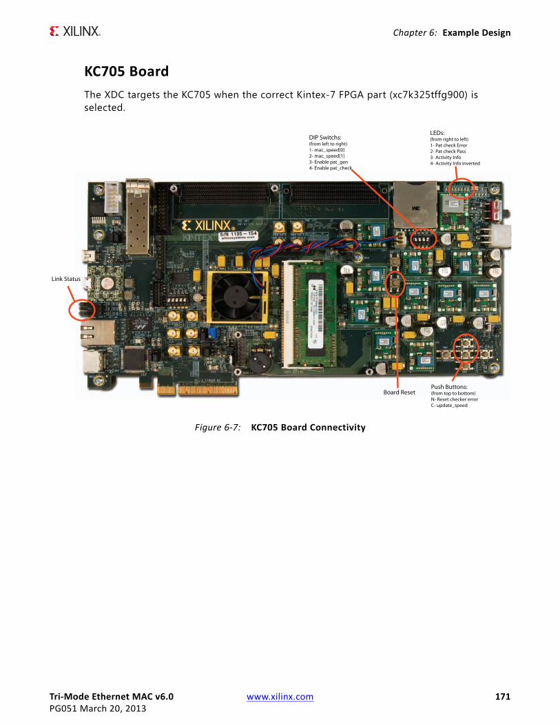
Tri-Mode Ethernet MAC v6.0 www.xilinx.com 171PG051 March 20, 2013
Chapter 6: Example Design
KC705 BoardThe XDC targets the KC705 when the correct Kintex-7 FPGA part (xc7k325tffg900) is selected.
X-Ref Target - Figure 6-7
Figure 6-7: KC705 Board Connectivity
Board Reset
LEDs:(from right to left)1- Pat check Error2- Pat check Pass3- Activity Info4- Activity Info inverted
DIP Switchs:(from left to right)1- mac_speed[0]2- mac_speed[1]3- Enable pat_gen4- Enable pat_check
Link Status
Push Buttons:(from top to bottom)N- Reset checker error C- update_speed
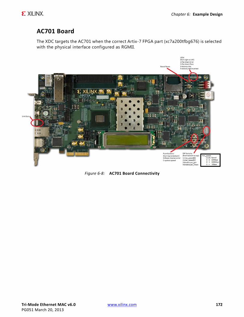
Tri-Mode Ethernet MAC v6.0 www.xilinx.com 172PG051 March 20, 2013
Chapter 6: Example Design
AC701 BoardThe XDC targets the AC701 when the correct Artix-7 FPGA part (xc7a200tfbg676) is selected with the physical interface configured as RGMII.
X-Ref Target - Figure 6-8
Figure 6-8: AC701 Board Connectivity
Tri-Mode Ethernet MAC v6.0 www.xilinx.com 173PG051 March 20, 2013
Appendix A
Calculating the MMCM Phase Shift or IODelay Tap Setting
Two differing methods can be used by the core to meet input bus (GMII/MII or RGMII) setup and hold timing specif ications. These are:
• MMCM Usage
A MMCM can be used in the receiver clock path to meet the input setup and hold requirements when implementing GMII/MII and RGMII. See the Physical Interface sections in this Guide in Chapter 3.
• IODelay Usage
IODelays can be used in the receiver clock path to meet the input setup and hold requirements when implementing GMII/MII and RGMII See the Physical Interface sections in this Guide in Chapter 3.
MMCM Usage
MMCM Phase Shifting RequirementsWhen using a MMCM, a f ixed-phase shift offset is applied to the receiver clock MMCM to skew the clock; this performs static alignment by using the receiver clock MMCM to shift the internal version of the receiver clock such that the input data is sampled at the optimum time. The ability to shift the internal clock in small increments is critical for sampling high-speed source synchronous signals. For statically aligned systems, the MMCM output clock phase offset (as set by the phase shift value) is a critical part of the system, as is the requirement that the PCB is designed with precise delay and impedance-matching for all the GMII/MII or RGMII receiver data bus and control signals.
You must determine the best MMCM setting (phase shift) to ensure that the target system has the maximum system margin to perform across voltage, temperature, and process (multiple chips) variations. Testing the system to determine the best MMCM phase shift setting has the added advantage of providing a benchmark of the system margin based on the UI (unit interval or bit time). System margin is defined as the following:
System Margin (ps) = UI(ps) × (working phase shift range/128)

Tri-Mode Ethernet MAC v6.0 www.xilinx.com 174PG051 March 20, 2013
Appendix A: Calculating the MMCM Phase Shift or IODelay Tap Setting
Finding the Ideal Phase Shift ValueXilinx cannot recommend a singular phase shift value that is effective across all hardware families. Xilinx does not recommend attempting to determine the phase shift setting empirically. In addition to the clock-to-data phase relationship, other factors such as package flight time (package skew) and clock routing delays (internal to the device) affect the clock to data relationship at the sample point (in the IOB) and are diff icult to characterize.
Xilinx recommends extensive investigation of the phase shift setting during hardware integration and debugging. The phase shift settings provided in the example design constraint f ile are placeholders, and work successfully in back-annotated simulation of the example design.
Perform a complete sweep of phase-shift settings during your initial system test. Use a test range which covers at least half of the clock period or 128 taps. This does not imply that 128 phase-shift values must be tested; increments of 4 (52, 56, 60, and so forth) correspond to roughly one MMCM tap at 125 MHz, and consequently provide an appropriate step size. Additionally, it is not necessary to characterize areas outside the working phase-shift range.
At the edge of the operating phase shift range, system behavior changes dramatically. In eight phase shift settings or less, the system can transition from no errors to exhibiting errors. Checking the operational edge at a step size of two (on more than one board) refines the typical operational phase shift range. After the range is determined, choose the average of the high and low working phase shift values as the default. During the production test, Xilinx recommends that you re-examine the working range at corner case operating conditions to determine whether any final adjustments to the final phase shift setting are needed.
You can use the FPGA Editor to generate the required test f ile set instead of resorting to multiple PAR runs. Performing the test on design f iles that differ only in phase shift setting prevents other variables from affecting the test results. FPGA Editor operations can even be scripted further, reducing the effort needed to perform this characterization.

Tri-Mode Ethernet MAC v6.0 www.xilinx.com 175PG051 March 20, 2013
Appendix A: Calculating the MMCM Phase Shift or IODelay Tap Setting
IODelay UsageIODelay Tap Setting RequirementsWith this method, an IODelay is used on either the clock or Data (or both) to adjust the Clock/Data relationship such that the input data is sampled at the optimum time. The ability to adjust this relationship in small increments is critical for sampling high-speed source synchronous signals. For statically aligned systems, the IODelay Tap setting is a critical part of the system, as is the requirement that the PCB is designed with precise delay and impedance-matching for all the GMII/MII or RGMII receiver data bus and control signals.
You must determine the best IODelay Tap setting to ensure that the target system has the maximum system margin to perform across voltage, temperature, and process (multiple chips) variations.
Finding the Ideal Tap Setting ValueXilinx cannot recommend a singular tap value that is effective across all hardware families. Xilinx does not recommend attempting to determine the tap setting empirically. In addition to the clock-to-data phase relationship, other factors such as package flight time (package skew) and clock routing delays (internal to the device) affect the clock to data relationship at the sample point (in the IOB) and are diff icult to characterize. Xilinx recommends extensive investigation of the tap setting during hardware integration and debugging. The tap settings provided in the example design constraint f ile are placeholders, and work successfully in back-annotated simulation of the example design.
Perform a complete sweep of tap settings during your initial system test. If possible use a test range which covers at least half of the clock period. This does not imply that all values must be tested as it might be simpler to use a large step size initially to identify a tighter range for a subsequent run. Additionally, it is not necessary to characterize areas outside the working range. If an IODelay is used on both Clock and Data then ensure this test range covers both clock only and data only adjustments.
At the edge of the operating range, system behavior changes dramatically. In four tap settings or less, the system can transition from no errors to exhibiting errors. Checking the operational edge at a step size of two (on more than one board) refines the typical operational range. After the range is determined, choose the average of the high and low working values as the default. During the production test, Xilinx recommends that you re-examine the working range at corner case operating conditions to determine whether any final adjustments to the final setting are needed. Where IODelays are used on the data it might be necessary or beneficial to use slightly different values for each bit.
You can use the FPGA Editor to generate the required test f ile set instead of resorting to multiple PAR runs. Performing the test on design f iles that differ only in tap setting prevents other variables from affecting the test results. FPGA Editor operations can even be scripted further, reducing the effort needed to perform this characterization.

Tri-Mode Ethernet MAC v6.0 www.xilinx.com 176PG051 March 20, 2013
Appendix B
Verification, Compliance, and Interoperability
The TEMAC solution has been verif ied with extensive simulation and hardware verif ication.
SimulationA highly paramerizable transaction based test bench was used to test the core. Testing included the following:
• Reset and Initialization
• Register Access including MDIO
• Frame transmission
• Frame reception, frame filtering and error handling
• All supported PHY interfaces
Hardware TestingThe example design provided with this core can be targeted to Reference Boards.
These designs have been used to perform hardware validation of the TEMAC solution. The KC705 and AC701 designs have been hardware tested using the Vivado™ Design Suite.
Tri-Mode Ethernet MAC v6.0 www.xilinx.com 177PG051 March 20, 2013
Appendix C
Migrating to AXI Tri-Mode Ethernet MACThis appendix describes migrating from older versions of the IP (prior to version 5.1) to the current IP release.
As of Tri-Mode Ethernet MAC v5.1 onwards the MAC uses an optional AXI4-Lite interface for the configuration, AXI4-Stream for data transfer, and has an entirely new memory map.
This Appendix describes the differences between the legacy interfaces used in prior versions and those in TEMAC version 5.1 and onwards.
Host Interface to AXI4-LiteThe management interface uses the industry standard AXI4-Lite to allow access to the Ethernet MAC core level. This interface replaces the Host interface for these operations:
• Configuring the MAC core
• Configuring the frame filter
• Accessing Statistics information
• Providing access to the MDIO interface
As these four features are now accessible using a single interface they have been combined into a single memory map. Table C-1 lists the AXI4-Lite registers and, if appropriate, their legacy host locations. For more details see Configuration and Status.

Tri-Mode Ethernet MAC v6.0 www.xilinx.com 178PG051 March 20, 2013
Appendix C: Migrating to AXI Tri-Mode Ethernet MAC
Table C-1: AXI4-LITE/Host Address Map Comparison
AXI4-LiteAddress
Legacy HostAddress Name Notes
0x200-0x204 0x001 Received bytes
Upper and lower words are separately addressed - but need to be linked, that is, upper access must follow lower access.
0x208-0x20C 0x000 Transmitted bytes
0x210-0x214 0x002 RX Undersize frames
0x218-0x21C 0x003 RX Fragment frames
0x220-0x224 0x004 RX 64-byte Frames
0x228-0x22C 0x005 RX 65-127-byte Frames
0x230-0x234 0x006 RX 128-255-byte Frames
0x238-0x23C 0x007 RX 256-511-byte Frames
0x240-0x244 0x008 RX 512-1023-byte Frames
0x248-0x24C 0x009 RX 1024-MaxFrameSize byte Frames
0x250-0x254 0x00A RX Oversize Frames
0x258-0x25C 0x00B TX 64-byte Frames
0x260-0x264 0x00C TX 65-127-byte Frames
0x268-0x26C 0x00D TX 128-255-byte Frames
0x270-0x274 0x00E TX 256-511-byte Frames
0x278-0x27C 0x00F TX 512-1023-byte Frames
0x280-0x284 0x010 TX 1024-MaxFrameSize byte Frames
0x288-0x28C 0x011 TX Oversize Frames
0x290-0x294 0x012 RX Good Frames
0x298-0x29C 0x013 RX Frame Check Sequence Errors
0x2A0-0x2A4 0x014 RX Good Broadcast Frames
0x2A8-0x2AC 0x015 RX Good Multicast Frames
0x2B0-0x2B4 0x016 RX Good Control Frames
0x2B8-0x2BC 0x017 RX Length/Type Out of Range
0x2C0-0x2C4 0x018 RX Good VLAN Tagged Frames
0x2C8-0x2CC 0x019 RX Good Pause Frames
0x2D0-0x2D4 0x01A RX Bad Opcode
0x2D8-0x2DC 0x01B TX Good Frames
0x2E0-0x2E4 0x01C TX Good Broadcast Frames
0x2E8-0x2EC 0x01D TX Good Multicast Frames
0x2F0-0x2F4 0x01E TX Good Underrun Errors
0x2F8-0x2FC 0x01F TX Good Control Frames
0x300-0x304 0x020 TX Good VLAN Tagged Frames
0x308-0x30C 0x021 TX Good Pause Frames
0x310-0x314 0x022 TX Single Collision Frames
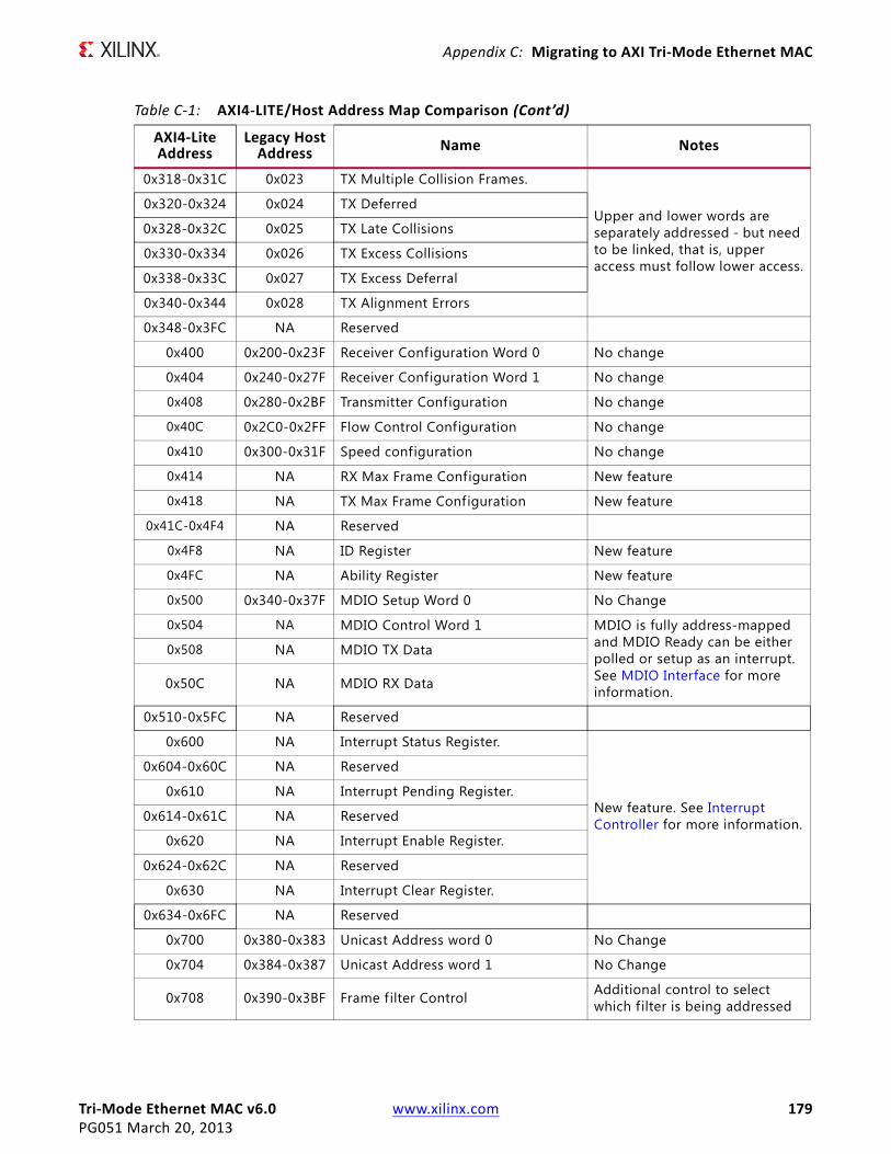
Tri-Mode Ethernet MAC v6.0 www.xilinx.com 179PG051 March 20, 2013
Appendix C: Migrating to AXI Tri-Mode Ethernet MAC
0x318-0x31C 0x023 TX Multiple Collision Frames.
Upper and lower words are separately addressed - but need to be linked, that is, upper access must follow lower access.
0x320-0x324 0x024 TX Deferred
0x328-0x32C 0x025 TX Late Collisions
0x330-0x334 0x026 TX Excess Collisions
0x338-0x33C 0x027 TX Excess Deferral
0x340-0x344 0x028 TX Alignment Errors
0x348-0x3FC NA Reserved
0x400 0x200-0x23F Receiver Configuration Word 0 No change
0x404 0x240-0x27F Receiver Configuration Word 1 No change
0x408 0x280-0x2BF Transmitter Configuration No change
0x40C 0x2C0-0x2FF Flow Control Configuration No change
0x410 0x300-0x31F Speed configuration No change
0x414 NA RX Max Frame Configuration New feature
0x418 NA TX Max Frame Configuration New feature
0x41C-0x4F4 NA Reserved
0x4F8 NA ID Register New feature
0x4FC NA Ability Register New feature
0x500 0x340-0x37F MDIO Setup Word 0 No Change
0x504 NA MDIO Control Word 1 MDIO is fully address-mapped and MDIO Ready can be either polled or setup as an interrupt. See MDIO Interface for more information.
0x508 NA MDIO TX Data
0x50C NA MDIO RX Data
0x510-0x5FC NA Reserved
0x600 NA Interrupt Status Register.
New feature. See Interrupt Controller for more information.
0x604-0x60C NA Reserved
0x610 NA Interrupt Pending Register.
0x614-0x61C NA Reserved
0x620 NA Interrupt Enable Register.
0x624-0x62C NA Reserved
0x630 NA Interrupt Clear Register.
0x634-0x6FC NA Reserved
0x700 0x380-0x383 Unicast Address word 0 No Change
0x704 0x384-0x387 Unicast Address word 1 No Change
0x708 0x390-0x3BF Frame filter Control Additional control to select which f ilter is being addressed
Table C-1: AXI4-LITE/Host Address Map Comparison (Cont’d)
AXI4-LiteAddress
Legacy HostAddress Name Notes
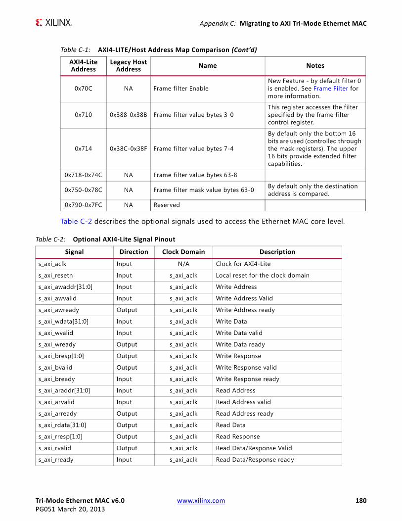
Tri-Mode Ethernet MAC v6.0 www.xilinx.com 180PG051 March 20, 2013
Appendix C: Migrating to AXI Tri-Mode Ethernet MAC
Table C-2 describes the optional signals used to access the Ethernet MAC core level.
0x70C NA Frame filter EnableNew Feature - by default f ilter 0 is enabled. See Frame Filter for more information.
0x710 0x388-0x38B Frame f ilter value bytes 3-0 This register accesses the filter specified by the frame filter control register.
0x714 0x38C-0x38F Frame f ilter value bytes 7-4
By default only the bottom 16 bits are used (controlled through the mask registers). The upper 16 bits provide extended f ilter capabilities.
0x718-0x74C NA Frame filter value bytes 63-8
0x750-0x78C NA Frame f ilter mask value bytes 63-0 By default only the destination address is compared.
0x790-0x7FC NA Reserved
Table C-1: AXI4-LITE/Host Address Map Comparison (Cont’d)
AXI4-LiteAddress
Legacy HostAddress Name Notes
Table C-2: Optional AXI4-Lite Signal Pinout
Signal Direction Clock Domain Description
s_axi_aclk Input N/A Clock for AXI4-Lite
s_axi_resetn Input s_axi_aclk Local reset for the clock domain
s_axi_awaddr[31:0] Input s_axi_aclk Write Address
s_axi_awvalid Input s_axi_aclk Write Address Valid
s_axi_awready Output s_axi_aclk Write Address ready
s_axi_wdata[31:0] Input s_axi_aclk Write Data
s_axi_wvalid Input s_axi_aclk Write Data valid
s_axi_wready Output s_axi_aclk Write Data ready
s_axi_bresp[1:0] Output s_axi_aclk Write Response
s_axi_bvalid Output s_axi_aclk Write Response valid
s_axi_bready Input s_axi_aclk Write Response ready
s_axi_araddr[31:0] Input s_axi_aclk Read Address
s_axi_arvalid Input s_axi_aclk Read Address valid
s_axi_arready Output s_axi_aclk Read Address ready
s_axi_rdata[31:0] Output s_axi_aclk Read Data
s_axi_rresp[1:0] Output s_axi_aclk Read Response
s_axi_rvalid Output s_axi_aclk Read Data/Response Valid
s_axi_rready Input s_axi_aclk Read Data/Response ready
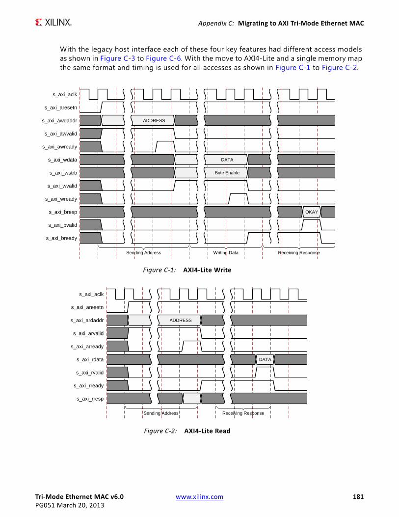
Tri-Mode Ethernet MAC v6.0 www.xilinx.com 181PG051 March 20, 2013
Appendix C: Migrating to AXI Tri-Mode Ethernet MAC
With the legacy host interface each of these four key features had different access models as shown in Figure C-3 to Figure C-6. With the move to AXI4-Lite and a single memory map the same format and timing is used for all accesses as shown in Figure C-1 to Figure C-2.
X-Ref Target - Figure C-1
Figure C-1: AXI4-Lite Write
s_axi_aclk
s_axi_aresetn
s_axi_awdaddr
s_axi_awvalid
s_axi_awready
s_axi_wdata
s_axi_wstrb
s_axi_wvalid
s_axi_wready
s_axi_bresp
s_axi_bvalid
s_axi_bready
ADDRESS
DATA
Byte Enable
OKAY
Sending Address Writing Data Receiving Response
X-Ref Target - Figure C-2
Figure C-2: AXI4-Lite Read
s_axi_aclk
s_axi_aresetn
s_axi_ardaddr
s_axi_arvalid
s_axi_arready
s_axi_rdata
s_axi_rvalid
s_axi_rready
s_axi_rresp
ADDRESS
DATA
Sending Address Receiving Response

Tri-Mode Ethernet MAC v6.0 www.xilinx.com 182PG051 March 20, 2013
Appendix C: Migrating to AXI Tri-Mode Ethernet MAC
Host MAC ConfigurationHost MAC configuration writes require the hostmiimsel to be driven low and hostaddr[9] to be driven high. A read or write is controlled by the hostopcode upper bit. host_req and host_rdy are not used.
AXI4-Lite accesses use a standard memory-mapped access as shown in Figure C-1 and Figure C-2. See MAC Configuration for more information.
Host Filter AccessHost f ilter accesses are controlled using a write to the filter control register at 0x18C (in the legacy core - an equivalent register does not exist from version 5.1 onwards). For writes the new filter data is split over two writes with the first setting the lower 32-bits of the 48-bit address and the control write setting the upper 16-bits of the 48-bit address and specifying the filter that is to be updated. For a read, the control register is written to specify a read and the filter to be read and the 48-bit address is returned over the following two cycles.
X-Ref Target - Figure C-3
Figure C-3: Host Interface MAC Configuration Read/Write
hostclk
hostmiimsel
hostopcode[1]
hostaddr[8:0]
hostaddr[9]
hostwrdata[31:0]
hostrddata[31:0]
Write Read
X-Ref Target - Figure C-4
Figure C-4: Address Filter Read/Write
hostclk
hostmiimsel
hostopcode[1]
hostaddr[8:0]
hostaddr[9]
hostwrdata[31:0]
hostrddata[31:0]
0x188 0x18C 0x18C
addr control control
Write Read

Tri-Mode Ethernet MAC v6.0 www.xilinx.com 183PG051 March 20, 2013
Appendix C: Migrating to AXI Tri-Mode Ethernet MAC
AXI4-Lite accesses use a standard memory-mapped access as shown in Figure C-1 and Figure C-2. However, the updated frame filter provides significantly more f iltering capabilities covering the entire f irst 64 bytes of any frame. The Frame Filter Control register (0x708) is therefore used to specify which of the available f ilters is being accessed by accesses in the range 0x70C to 0x790.
To access a particular f ilter:
• Write to the Frame Filter Control register(0x708) to select the Filter
• Write or read to the specified f ilter register
See Frame Filter for more information.
Host Statistics ReadHost Statistics reads make use of the host_req to initialize an access, with hostmiimsel and hostaddr[9] being low to indicate a statistics access is required.
The stats specific host_stats_lsw_rdy and host_stats_msw_rdy output indicate when valid stats data is present on the read data bus. This data is always presented 6 cycles after the request is initiated.
AXI4-Lite accesses use a standard memory-mapped access as shown in Figure C-1 and Figure C-2. However, there is a read-order requirement if the full 64-bit statistics value is desired. In all cases the lowest location must f irst be read, this causes the upper 32-bit value to be captured. The following read, to the statistics block, can either be to the related upper 32-bit location OR to another statistics counter lower 32-bit location. A read to another counter upper 32-bit location results in an error. See Statistics Counters for more detail.
X-Ref Target - Figure C-5
Figure C-5: Statistics Read
hostclk
hostmiimsel
host_req
hostaddr[8:0]
hostaddr[9]
hostrddata[31:0]
host_stats_lsw_rdy
host_stats_msw_rdy
LSW MSW
6 clocks
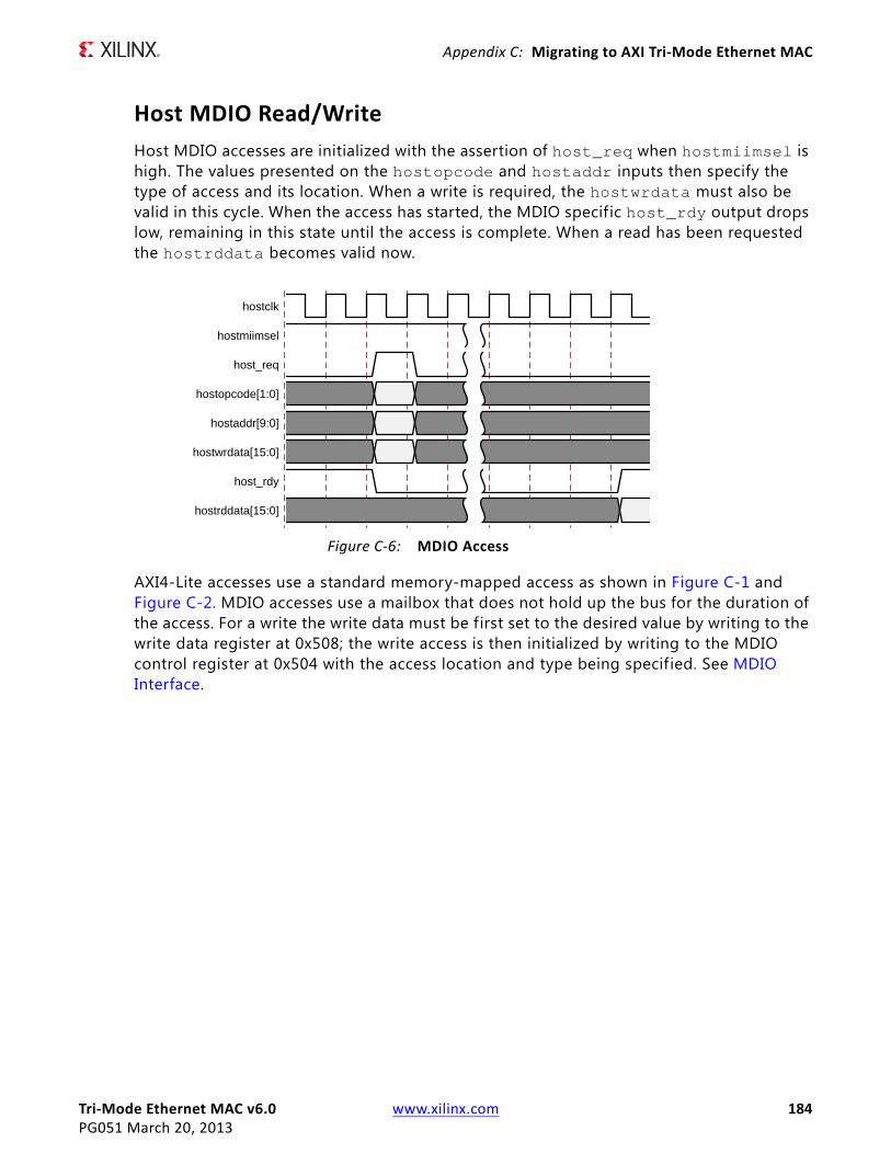
Tri-Mode Ethernet MAC v6.0 www.xilinx.com 184PG051 March 20, 2013
Appendix C: Migrating to AXI Tri-Mode Ethernet MAC
Host MDIO Read/WriteHost MDIO accesses are initialized with the assertion of host_req when hostmiimsel is high. The values presented on the hostopcode and hostaddr inputs then specify the type of access and its location. When a write is required, the hostwrdata must also be valid in this cycle. When the access has started, the MDIO specific host_rdy output drops low, remaining in this state until the access is complete. When a read has been requested the hostrddata becomes valid now.
AXI4-Lite accesses use a standard memory-mapped access as shown in Figure C-1 and Figure C-2. MDIO accesses use a mailbox that does not hold up the bus for the duration of the access. For a write the write data must be first set to the desired value by writing to the write data register at 0x508; the write access is then initialized by writing to the MDIO control register at 0x504 with the access location and type being specified. See MDIO Interface.
X-Ref Target - Figure C-6
Figure C-6: MDIO Access
hostclk
hostmiimsel
host_req
hostopcode[1:0]
hostaddr[9:0]
hostwrdata[15:0]
host_rdy
hostrddata[15:0]

Tri-Mode Ethernet MAC v6.0 www.xilinx.com 185PG051 March 20, 2013
Appendix C: Migrating to AXI Tri-Mode Ethernet MAC
For a read only, the MDIO control register write is required.
X-Ref Target - Figure C-7
Figure C-7: AXI4-Lite MDIO Write Access
s_axi_clk
s_axi_awaddr
s_axi_awvalid
s_axi_awready
s_axi_wdata
s_axi_wstrb
s_axi_wvalid
s_axi_wready
s_axi_bresp
s_axi_bvalid
s_axi_bready
s_axi_araddr
s_axi_arvalid
s_axi_arready
s_axi_rdata
s_axi_rvalid
s_axi_rready
s_axi_rresp
0x508 0x504
WRDATA CONTROL
0xF 0xF
OKAY OKAY
0x504
STATUS
OKAY
Write data Write ControlPoll MDIO Status
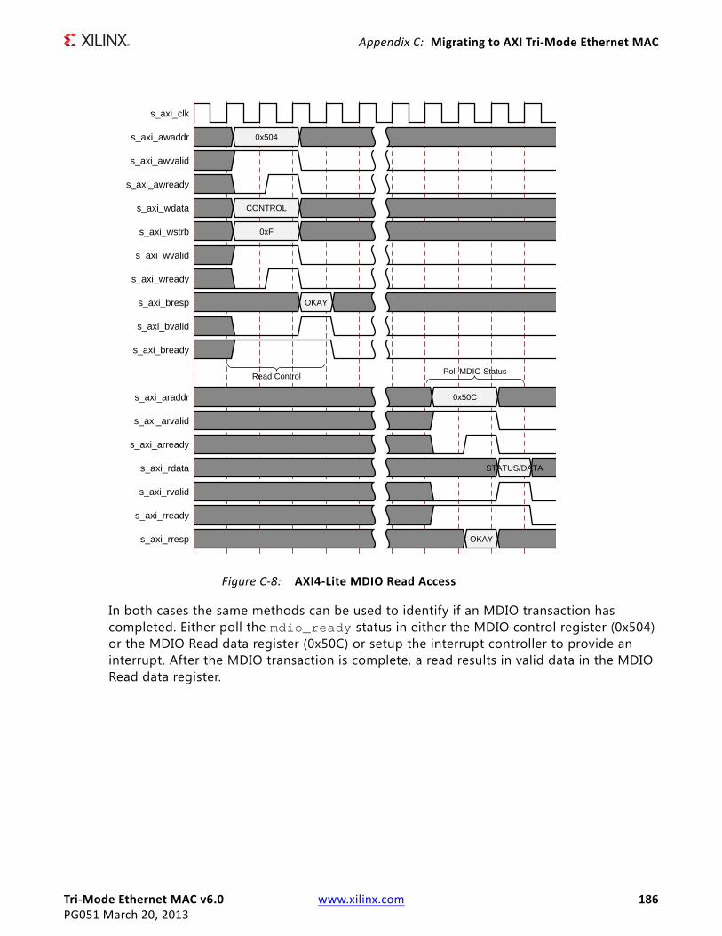
Tri-Mode Ethernet MAC v6.0 www.xilinx.com 186PG051 March 20, 2013
Appendix C: Migrating to AXI Tri-Mode Ethernet MAC
In both cases the same methods can be used to identify if an MDIO transaction has completed. Either poll the mdio_ready status in either the MDIO control register (0x504) or the MDIO Read data register (0x50C) or setup the interrupt controller to provide an interrupt. After the MDIO transaction is complete, a read results in valid data in the MDIO Read data register.
X-Ref Target - Figure C-8
Figure C-8: AXI4-Lite MDIO Read Access
s_axi_clk
s_axi_awaddr
s_axi_awvalid
s_axi_awready
s_axi_wdata
s_axi_wstrb
s_axi_wvalid
s_axi_wready
s_axi_bresp
s_axi_bvalid
s_axi_bready
s_axi_araddr
s_axi_arvalid
s_axi_arready
s_axi_rdata
s_axi_rvalid
s_axi_rready
s_axi_rresp
0x504
CONTROL
0xF
OKAY
0x50C
STATUS/DATA
OKAY
Read ControlPoll MDIO Status

Tri-Mode Ethernet MAC v6.0 www.xilinx.com 187PG051 March 20, 2013
Appendix C: Migrating to AXI Tri-Mode Ethernet MAC
Client Interface to AXI4-StreamThe following tables show the RX and TX AXI4-Stream signals.
TX Client Interface versus TX AXI4-StreamThe TX client interface requires the use of an acknowledge from the MAC to identify when a data transfer can continue; this is shown in Figure C-9.
The key requirement is that the first byte of a frame is presented to the MAC, with txdvld high, and then held until tx_ack is asserted. The MAC expects new data on the following cycle, and on each valid cycle after that until the end of the frame. The deassertion of txdvld identif ies the end of the frame.
If data cannot be made available at the required rate, you are expected to assert tx_underrun to ensure the frame is errored. For lower rates, where data is only not required on every physical cycle, it is expected that a clock enable is used to control the data rate.
Table C-3: TX AXI4-Stream Signal Pinout
Signal Direction Clock Domain Description
tx_mac_clk Input N/A Clock for AXI4-Stream
tx_axis_mac_tdata Input tx_mac_clk Data
tx_axis_mac_tvalid Input tx_mac_clk Data Valid
tx_axis_mac_tlast input tx_mac_clk Final transfer of frame
tx_axis_mac_tuser Input tx_mac_clk Explicit Error indication
tx_axis_mac_tready output tx_mac_clk MAC ready for data
Table C-4: RX AXI4-Stream Signal Pinout
Signal Direction Clock Domain Description
rx_mac_clk Input N/A Clock for AXI4-Stream
rx_axis_mac_tdata Output rx_mac_clk Data
rx_axis_mac_tvalid Output rx_mac_clk Data Valid
rx_axis_mac_tlast Output rx_mac_clk f inal transfer of frame
rx_axis_mac_tuser Output rx_mac_clk Frame good/bad indication

Tri-Mode Ethernet MAC v6.0 www.xilinx.com 188PG051 March 20, 2013
Appendix C: Migrating to AXI Tri-Mode Ethernet MAC
The TX AXI4-Stream access is also shown in Figure C-9. Because there is no built-in FIFO to allow throttling of frame data, the requirement still exists to always provide data to the MAC when requested. However, AXI4-Stream uses a standard ready/valid handshake throughout the frame and requires the final byte of the frame to be identif ied with tlast.
The TX AXI4-Stream interface allows for both implicit and explicit error insertion. In the case of frame underrun, the valid would be dropped mid-frame and, if tlast was not asserted on the previous cycle, this would implicitly create an error. Deasserting the tuser input allows an error to be forced under direct user control.
In the case of lower rates, the is no difference in the required user logic as tready is used to actively control the data throughput.
RX Client Interface versus RX AXI4-StreamThe RX Client interface, shown in Figure C-10, outputs data as received from the PHY, with a frame good or frame bad indication being set when the frame is complete. For lower rates a clock enable is used to control the data throughput.
X-Ref Target - Figure C-9
Figure C-9: TX Client access vs TX AXI4-Stream
TX Client Interface
tx_clk
txd[7:0]
txdvld
tx_ack
tx_underrun
TX AXI4 Stream Interface
tx_axis_mac_tdata
tx_axis_mac_tvalid
tx_axis_mac_tlast
tx_axis_mac_tuser
tx_axis_mac_tready
DA SA L/T DATA
DA SA L/T DATA
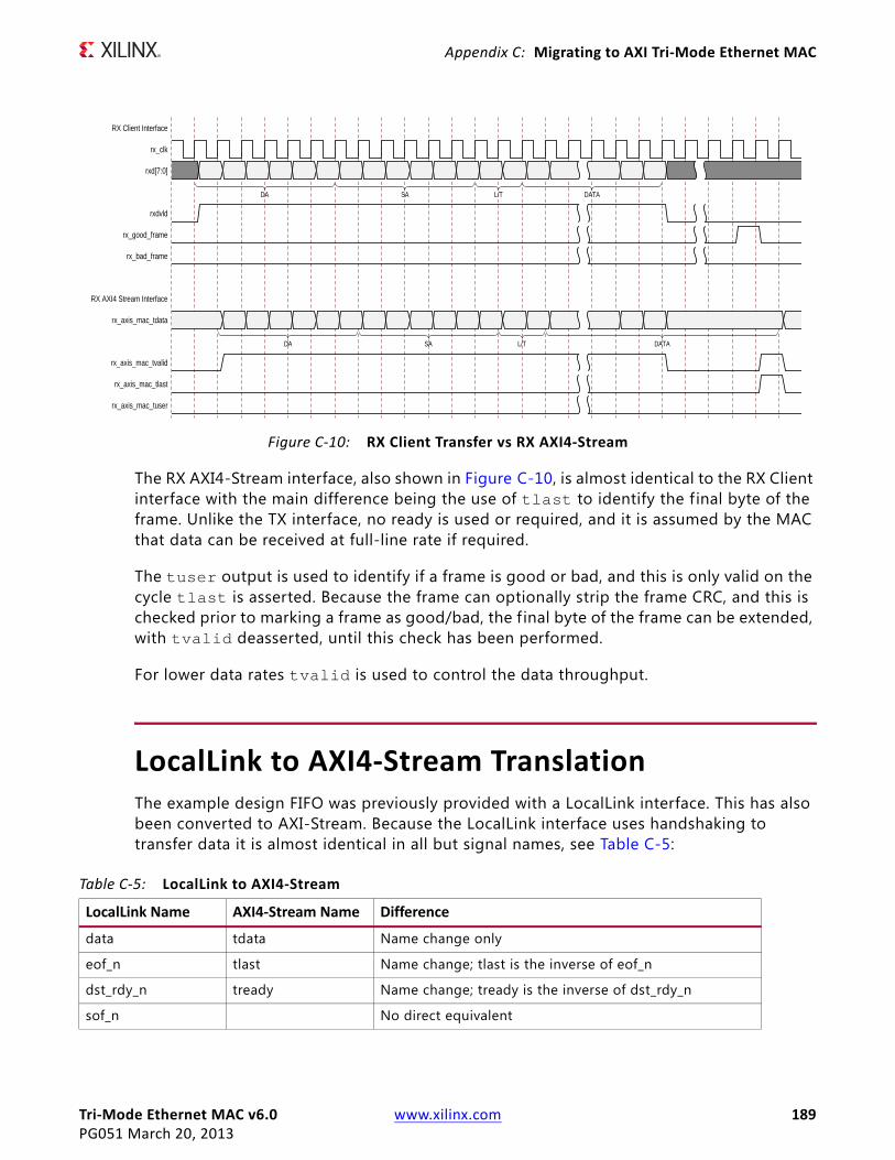
Tri-Mode Ethernet MAC v6.0 www.xilinx.com 189PG051 March 20, 2013
Appendix C: Migrating to AXI Tri-Mode Ethernet MAC
The RX AXI4-Stream interface, also shown in Figure C-10, is almost identical to the RX Client interface with the main difference being the use of tlast to identify the f inal byte of the frame. Unlike the TX interface, no ready is used or required, and it is assumed by the MAC that data can be received at full-line rate if required.
The tuser output is used to identify if a frame is good or bad, and this is only valid on the cycle tlast is asserted. Because the frame can optionally strip the frame CRC, and this is checked prior to marking a frame as good/bad, the f inal byte of the frame can be extended, with tvalid deasserted, until this check has been performed.
For lower data rates tvalid is used to control the data throughput.
LocalLink to AXI4-Stream TranslationThe example design FIFO was previously provided with a LocalLink interface. This has also been converted to AXI-Stream. Because the LocalLink interface uses handshaking to transfer data it is almost identical in all but signal names, see Table C-5:
X-Ref Target - Figure C-10
Figure C-10: RX Client Transfer vs RX AXI4-Stream
RX Client Interface
rx_clk
rxd[7:0]
rxdvld
rx_good_frame
rx_bad_frame
RX AXI4 Stream Interface
rx_axis_mac_tdata
rx_axis_mac_tvalid
rx_axis_mac_tlast
rx_axis_mac_tuser
DA SA L/T DATA
DA SA L/T DATA
Table C-5: LocalLink to AXI4-Stream
LocalLink Name AXI4-Stream Name Difference
data tdata Name change only
eof_n tlast Name change; tlast is the inverse of eof_n
dst_rdy_n tready Name change; tready is the inverse of dst_rdy_n
sof_n No direct equivalent

Tri-Mode Ethernet MAC v6.0 www.xilinx.com 190PG051 March 20, 2013
Appendix C: Migrating to AXI Tri-Mode Ethernet MAC
Figure C-11 shows a LocalLink transfer and the associated AXI4-Stream signals. This is identical for both TX and RX.
src_rdy_n No direct equivalent
tvalid Generated from sof_n and src_rdy_n. tvalid can only be high when valid frame data is present.
Table C-5: LocalLink to AXI4-Stream (Cont’d)
LocalLink Name AXI4-Stream Name Difference
X-Ref Target - Figure C-11
Figure C-11: LocalLink vs AXI4-Stream
LocalLink Interface
clk
data
sof_n
eof_n
src_rdy_n
dst_rdy_n
AXI4-Stream Interface
tdata
tvalid
tready
tlast

Tri-Mode Ethernet MAC v6.0 www.xilinx.com 191PG051 March 20, 2013
Appendix D
DebuggingThis appendix includes details about resources available on the Xilinx Support website and debugging tools. In addition, this appendix provides a step-by-step process for debugging process and a flow diagram to guide you through debugging the Tri-Mode Ethernet Media Access Controller (TEMAC) core.
The following topics are included in this appendix:
• Finding Help on Xilinx.com
• Debug Tools
• Simulation Debug
• Implementation and Timing Errors
• Hardware Debug
Finding Help on Xilinx.comTo help in the design and debug process when using the Tri-Mode Ethernet MAC, the Xilinx Support web page contains key resources such as product documentation, release notes, answer records, information about known issues, and links for opening a Technical Support WebCase.
DocumentationThis product guide is the main document associated with the Tri-Mode Ethernet MAC. This guide, along with documentation related to all products that aid in the design process, can be found on the Xilinx Support web page (www.xilinx.com/support) or by using the Xilinx Documentation Navigator.
Download the Xilinx Documentation Navigator from the Design Tools tab on the Downloads page (www.xilinx.com/download). For more information about this tool and the features available, open the online help after installation.

Tri-Mode Ethernet MAC v6.0 www.xilinx.com 192PG051 March 20, 2013
Appendix D: Debugging
Solution CentersSee the Xilinx Solution Centers for support on devices, software tools, and intellectual property at all stages of the design cycle. Topics include design assistance, advisories, and troubleshooting tips.
The Solution Center specific to the Tri-Mode Ethernet MAC core is located at Xilinx Ethernet IP Solution Center.
Known IssuesAnswer Records include information about commonly encountered problems, helpful information on how to resolve these problems, and any known issues with a Xilinx product. Answer Records are created and maintained daily ensuring that users have access to the most accurate information available.
Answer Records for this core are listed below, and can also be located by using the Search Support box on the main Xilinx support web page. To maximize your search results, use proper keywords such as:
• Product name
• Tool message(s)
• Summary of the issue encountered
A filter search is available after results are returned to further target the results.
Master Answer Record for the Tri-Mode Ethernet MAC
AR 54251
Contacting Technical SupportXilinx provides technical support at www.xilinx.com/support for this LogiCORE™ IP product when used as described in the product documentation. Xilinx cannot guarantee timing, functionality, or support of product if implemented in devices that are not defined in the documentation, if customized beyond that allowed in the product documentation, or if changes are made to any section of the design labeled DO NOT MODIFY.
To contact Xilinx Technical Support:
1. Navigate to www.xilinx.com/support.
2. Open a WebCase by selecting the WebCase link located under Support Quick Links.

Tri-Mode Ethernet MAC v6.0 www.xilinx.com 193PG051 March 20, 2013
Appendix D: Debugging
When opening a WebCase, include:
• Target FPGA including package and speed grade.
• All applicable Xilinx Design Tools and simulator software versions.
• Additional f iles based on the specif ic issue might also be required. See the relevant sections in this debug guide for guidelines about which f ile(s) to include with the WebCase.
Debug ToolsThere are many tools available to debug Ethernet MAC design issues. It is important to know which tools are useful for debugging various situations. This section references the following tools:
Example DesignThe Tri-Mode Ethernet Media Access Controller (TEMAC) comes with a synthesizable example design complete with a functional test benches. Information on the example design can be found in Chapter 6, Example Design.
Vivado Lab ToolsVivado inserts logic analyzer and virtual I/O cores directly into your design. Vivado Lab Tools allows you to set trigger conditions to capture application and integrated block port signals in hardware. Captured signals can then be analyzed. This feature represents the functionality in the Vivado IDE that is used for logic debugging and validation of a design running in Xilinx FPGA devices in hardware.
The Vivado logic analyzer is used to interact with the logic debug LogiCORE IP cores, including:
• ILA 2.0 (and later versions)
• VIO 2.0 (and later versions)
Tri-Mode Ethernet MAC v6.0 www.xilinx.com 194PG051 March 20, 2013
Appendix D: Debugging
Reference BoardsVarious Xilinx development boards support 10/100/1000 Mb/s Ethernet. These boards can be used to prototype designs and establish that the core can communicate with the system.
The provided example design can, if generated with the correct part and core options, be targeted directly to the following list of boards. For more information, see Targeting the Example Design to a Board, page 169.
• 7 Series evaluation boards
° KC705
° AC701
Link AnalyzersLink analyzers can be used to generate and analyze traff ic for hardware debug and testing. Common link analyzers include:
• Spirent SmartBits
• IXIA brand 10/100/1000 Ethernet test chassis
• Wireshark (a free packet sniffer software application)
Simulation DebugThe simulation debug flow for Questa® SIM is shown in Figure D-1. A similar approach can be used with other simulators.

Tri-Mode Ethernet MAC v6.0 www.xilinx.com 195PG051 March 20, 2013
Appendix D: Debugging
Compiling Simulation LibrariesCompile the Xilinx simulation libraries, either by using the Xilinx Simulation Library Compilation Wizard, or by using the compxlib command line tool.
X-Ref Target - Figure D-1
Figure D-1: Questa SIM Debug Flow Chart
Tri-Mode Ethernet MAC v6.0 www.xilinx.com 196PG051 March 20, 2013
Appendix D: Debugging
Xilinx Simulation Library Compilation Wizard
A GUI wizard provided as part of the Xilinx software can be launched to assist in compiling the simulation libraries by typing compxlib in the command prompt.
For more information see the Software Manuals and specif ically the Command Line Tools Reference Guide under the section titled compxlib.
Assuming the Xilinx and Questa SIM environments are set up correctly, this is an example of compiling the SecureIP and UNISIMs libraries for Verilog into the current directory.
compxlib -s mti_se -arch virtex7 -l verilog -lib secureip -lib unisims -dir ./
There are many other options available for compxlib described in the Command Line Tools Reference Guide [Ref 14].
Compxlib produces a questasim.ini f ile containing the library mappings. In Questa SIM, to see the current library mappings, type vmap at the prompt. The mappings can be updated in the .ini f ile or to map a library at the Questa SIM prompt type:
vmap [<logical_name>] [<path>]
For example:
vmap unisims_ver C:\my_unisim_lib
Implementation and Timing Errors
Regional Clocking ErrorsWhen implementing the Ethernet MAC with either a GMII or RGMII physical interface, regional clocking methodologies are used. This means that there are the following requirements:
1. The receive-side physical interface clock (GMII_RX_CLK for GMII, or RGMII_RXC for RGMII) must be placed at a clock-capable I/O (CCIO) pin. If this requirement is not met, an error similar to the following one might be seen during implementation:
ERROR:Place:839 - The component GMII_RX_CLK has been physically constrained to a location which is an invalid placement for this component.
2. All receive-side physical interface signals must be placed at package pins that correspond to the same clock region as the receive-side physical interface. If this requirement is not met, an error similar to the following might be seen during implementation:

Tri-Mode Ethernet MAC v6.0 www.xilinx.com 197PG051 March 20, 2013
Appendix D: Debugging
ERROR:Place:901 - IO Clock Net "gmii_rx_clk_bufio" cannot possibly be routed to component v6_emac_gmii_locallink_inst/v6_emac_gmii_block_inst/gmii/RXD_TO_MA C<2>" (placed in clock region "CLOCKREGION_X0Y1"), since it is too far away from source BUFIO "bufio_rx" (placed in clock region "CLOCKREGION_X1Y1"). The situation may be caused by user constraints, or the complexity of the design. Constraining the components related to the regional clock properly may guide the tool to find a solution.
For more information on these requirements, see the Vivado™ Design Suite, I/O Standard and Placement in Chapter 5
Timing Failed for GMII/RGMII/MII OFFSET IN ConstraintTo satisfy setup and hold requirements for these standards, either:
• f ixed-mode IODELAYs are placed on the receive data and control signals when using the GMII, RGMII, or MII wrapper f iles.
In the example design XDC, the f ixed value delays are set based on the pinout used in the example design. With a different pinout, it might be required to adjust the f ixed DELAY value to still meet the setup and hold requirements.
• An MMCM is used on the input clock source for the GMII, RGMII or MII.
In the example design XDC, a f ixed phase shift value is set, based on the pinout used in the example design. With a different pinout, it might be required to adjust the phase shift value to still meet the setup and hold requirements.
For more details on how to adjust this delay to meet setup and hold requirements, see the Vivado Design Suite, I/O Standard and Placement in Chapter 5
Hardware DebugHardware issues can range from link bring-up to problems seen after hours of testing. This section provides debug steps for common issues. The Vivado Analyzer tool is a valuable resource to use in hardware debug and the signal names mentioned in the following individual sections can be probed using the Vivado Analyzer tool for debugging the specif ic problems. Many of these common issues can also be applied to debugging design simulations. Details are provided on:
• General Checks
• Problems with Transmitting and Receiving Frames
• Problems with the MDIO
• Configuring the Ethernet MAC to the Correct Speed

Tri-Mode Ethernet MAC v6.0 www.xilinx.com 198PG051 March 20, 2013
Appendix D: Debugging
General Checks• Ensure that all the timing constraints for the core were properly incorporated from the
example design and that all constraints were met during implementation.
• Does it work in post-place and route timing simulation? If problems are seen in hardware but not in timing simulation, this could indicate a PCB issue.
• Ensure that all clock sources are active and clean. If using MMCMs in the design, ensure that all MMCMs have obtained lock by monitoring the LOCKED port.
Problems with Transmitting and Receiving FramesProblems with data reception or transmission can be caused by a wide range of factors. The following list contains common causes to check for:
• Verify that the whole TEMAC block is not being held in reset. The whole block is held in reset if the main reset input or if a locked signal from an MMCM is low.
• Verify that both the receiver and transmitter are enabled and not being held in reset. For more information, see the receiver and transmitter configuration words in Table 2-24, page 36 and Table 2-26, page 37 respectively.
• Verify that the TEMAC is configured correctly and that the latest core version is being used. Try running a simulation to check if the failure is hardware-specific.
• If using GMII or RGMII, check if setup and hold requirements are met For more information, see the section on debugging Implementation and Timing Errors.
• Verify that the link is up between the PHY and its link partner. If using the Ethernet 1000BASE-X PCS/PMA or SGMII core, see the Debugging Guide section of the LogiCORE IP Ethernet 1000BASE-X PCS/PMA or SGMII Product Guide [Ref 1]
• If using an external PHY, is data received correctly if the PHY is put in loopback? If so, the issue might be on the link between the PHY and its link partner.
• Check if the address f ilter is enabled. If frames are not being received correctly, try disabling the address filter to ensure that the frame is not being dropped by the address f ilter. For more information, see Frame Filter in Chapter 3.
• Verify that the TEMAC has been configured to operate at the correct speed negotiated with the PHY.
• Are received frames being dropped by user logic because rx_axis_mac_tuser is asserted? See Frame Reception with Errors in Chapter 3 for details on why frames are marked bad by the Ethernet MAC. The Vivado Analyzer tool can be inserted to get more details on the bad frames.
• Add the Vivado Analyzer tool to the design to look at the RX and TX AXI4-Stream and physical interface data signals, control signals and statistics vectors.

Tri-Mode Ethernet MAC v6.0 www.xilinx.com 199PG051 March 20, 2013
Appendix D: Debugging
Problems with the MDIOSee Accessing PHY Configuration Registers, through MDIO Using the Management Interface in Chapter 3 for detailed information about performing MDIO transactions.
Things to check for:
• Check that the MDC clock is running and that the frequency is 2.5 MHz or less. If using the MDIO control registers to perform MDIO accesses, the MDIO interface does not work until the clock frequency is set with CLOCK_DIVIDE. The MDIO clock with a maximum frequency of 2.5 MHz is derived from the s_axi_aclk clock.
• Ensure that the TEMAC and PHY are not held in reset. Be sure to check the polarity of the reset to your external PHY. Many PHYs have an active-low reset.
• Read from a configuration register that does not have all 0s as a default. If all 0s are read back, the read was unsuccessful.
• If using the management interface to access the MDIO, check if the issue is just with the MDIO control registers or if there are also issues reading and writing MAC registers with the management interface.
• If accessing MDIO registers of the Ethernet 1000BASE-X PCS/PMA or SGMII core, check that the PHYAD field placed into the MDIO frame matches the value placed on the phyad[4:0] port of the Ethernet 1000BASE-X PCS/PMA or SGMII core.
• Has a simulation been run? Verify in simulation and/or a Vivado Analyzer tool capture that the waveform is correct for accessing the management interface for a MDIO read/write. The demonstration test bench delivered with the core provides an example of MDIO accesses.
Configuring the Ethernet MAC to the Correct SpeedWhen operating in tri-mode, the PHY negotiates the highest speed available with its link partner. The speed of the Ethernet MAC can be set by the user application after auto-negotiation completes by doing the following:
1. The user application can either monitor auto-negotiation interrupt from the external PHY or internal Ethernet 1000BASE-X PCSPMA or SGMII core, or poll for auto-negotiation (see the relevant PHY documentation).
2. When auto-negotiation completes the user application can read the MDIO auto-negotiation registers to obtain the negotiated speed.
3. The user application then needs to set this speed in the Ethernet MAC configuration registers using the host interface.
If auto-negotiation is disabled, the Ethernet MAC, PHY, and the PHY link partner must all be set to the same speed.
Tri-Mode Ethernet MAC v6.0 www.xilinx.com 200PG051 March 20, 2013
Appendix E
Additional Resources
Xilinx ResourcesFor support resources such as Answers, Documentation, Downloads, and Forums, see Appendix D, Debugging and Xilinx Support website at:
www.xilinx.com/support.
For a glossary of technical terms used in Xilinx documentation, see:
www.xilinx.com/company/terms.htm.
ReferencesThese documents provide supplemental material useful with this user guide:
1. Ethernet 1000BASE-X PCS/PMA or SGMII Product Guide (PG047)
2. 7 Series Data Sheets
3. 7 Series FPGAs Configuration User Guide (UG470)
4. 7 Series FPGAs Clocking Resources User Guide (UG472)
5. 7 Series FPGAs Configurable Logic Block User Guide (UG474)
6. Vivado™ Design Suite user documentation
7. Vivado Design Suite User Guide, Designing with IP (UG896)
8. IEEE 802.3-2008 specif ication
9. Reduced Gigabit Media Independent Interface (RGMII), version 2.0
10. Tri-Mode Ethernet MAC User Guide (UG777)
11. AXI Ethernet Data Sheet (DS759)
12. AMBA AXI4-Stream Protocol Specification
13. Xilinx Synthesis and Simulation Design Guide
Tri-Mode Ethernet MAC v6.0 www.xilinx.com 201PG051 March 20, 2013
Appendix E: Additional Resources
14. Xilinx Command Line Tools User Guide (UG628)
15. IEEE 802.1AS, Timing and Synchronization for Time-Sensitive Applications in Bridged Local Area Networks
16. IEEE 802.1BA-2011, Audio Video Bridging (AVB) Systems
17. IEEE 802.1Q-2011, Media Access Control (MAC) Bridges and Virtual Bridged Local Area Networks
18. IEEE 1588, A Precision Clock Synchronization Protocol for Networked Measurement and Control Systems
Revision HistoryThe following table shows the revision history for this document.
Date Version Revision
07/25/2012 1.0 Initial Xilinx release. This Product Guide is derived from DS818 and UG777.
12/18/2012 2.0 • Updated to v5.5, ISE Design Suite 14.4/Vivado Design Suite 2012.4.• Removed Windows and Linux references in System Requirements.• Updated License and Ordering section.• Added note on IEEE 1588 timestamping in Timestamping Logic section
and IP Features.• Updated to 6 cycles in Frame Collisions – Half Duplex Operation section• Updated “bytes of transmit data” to Interframe Gap Adjustment
Full-Duplex section• Updated GMII and RGMII subsections with 7 series in 1 Gb/s Only
Ethernet MAC IP Core and Tri-Speed (10 Mb/s, 100 Mb/s, and 1 Gb/s) Ethernet MAC IP Core sections
• Updated GUI in Fig. 4-1• Updated State Machine Flow Diagram in Fig. 6-5• Updated GUI in Fig. 7-1• Updated Debug section and minor document updates.
03/20/2013 2.1 • Updated to v6.0 for Vivado Design Suite only. Removed ISE.• Updated Device Utilization tables (Table 2-1 to 2-4).• Updated descriptions in Port Descriptions.• tx_enable, rx_enable, speedis10100 and speedis100 outputs now
present for all parameterizations• tx_axis_mac_tuser is now defined as std_logic_vector for all VHDL
parameterizations• Updated Figs. 4-1 and 4-2 GUIs• Updated AXI4-Lite Control State Machine in Example Design chapter.• Added Artix-7 AC701 board support in Example Design chapter.• Updated to Questa SIM.

Tri-Mode Ethernet MAC v6.0 www.xilinx.com 202PG051 March 20, 2013
Appendix E: Additional Resources
Notice of DisclaimerThe information disclosed to you hereunder (the “Materials”) is provided solely for the selection and use of Xilinx products. To the maximum extent permitted by applicable law: (1) Materials are made available “AS IS” and with all faults, Xilinx hereby DISCLAIMS ALL WARRANTIES AND CONDITIONS, EXPRESS, IMPLIED, OR STATUTORY, INCLUDING BUT NOT LIMITED TO WARRANTIES OF MERCHANTABILITY, NON-INFRINGEMENT, OR FITNESS FOR ANY PARTICULAR PURPOSE; and (2) Xilinx shall not be liable (whether in contract or tort, including negligence, or under any other theory of liability) for any loss or damage of any kind or nature related to, arising under, or in connection with, the Materials (including your use of the Materials), including for any direct, indirect, special, incidental, or consequential loss or damage (including loss of data, profits, goodwill, or any type of loss or damage suffered as a result of any action brought by a third party) even if such damage or loss was reasonably foreseeable or Xilinx had been advised of the possibility of the same. Xilinx assumes no obligation to correct any errors contained in the Materials or to notify you of updates to the Materials or to product specifications. You may not reproduce, modify, distribute, or publicly display the Materials without prior written consent. Certain products are subject to the terms and conditions of the Limited Warranties which can be viewed at http://www.xilinx.com/warranty.htm; IP cores may be subject to warranty and support terms contained in a license issued to you by Xilinx. Xilinx products are not designed or intended to be fail-safe or for use in any application requiring fail-safe performance; you assume sole risk and liability for use of Xilinx products in Critical Applications: http://www.xilinx.com/warranty.htm#critapps.© Copyright 2012–2013 Xilinx, Inc. Xilinx, the Xilinx logo, Artix, ISE, Kintex, Spartan, Virtex, Vivado, Zynq, and other designated brands included herein are trademarks of Xilinx in the United States and other countries. All other trademarks are the property of their respective owners.