10g ethernet mac v15.1 logicore ip product guide (pg072)
TRANSCRIPT
10G Ethernet MAC v15.1
LogiCORE IP Product Guide
Vivado Design Suite
PG072 October 4, 2017
10G Ethernet MAC v15.1 2PG072 October 4, 2017 www.xilinx.com
Table of ContentsIP Facts
Chapter 1: OverviewFeature Summary. . . . . . . . . . . . . . . . . . . . . . . . . . . . . . . . . . . . . . . . . . . . . . . . . . . . . . . . . . . . . . . . . . 5Applications . . . . . . . . . . . . . . . . . . . . . . . . . . . . . . . . . . . . . . . . . . . . . . . . . . . . . . . . . . . . . . . . . . . . . . 6Licensing and Ordering . . . . . . . . . . . . . . . . . . . . . . . . . . . . . . . . . . . . . . . . . . . . . . . . . . . . . . . . . . . . . 7
Chapter 2: Product SpecificationStandards . . . . . . . . . . . . . . . . . . . . . . . . . . . . . . . . . . . . . . . . . . . . . . . . . . . . . . . . . . . . . . . . . . . . . . . 10Performance. . . . . . . . . . . . . . . . . . . . . . . . . . . . . . . . . . . . . . . . . . . . . . . . . . . . . . . . . . . . . . . . . . . . . 10Resource Utilization. . . . . . . . . . . . . . . . . . . . . . . . . . . . . . . . . . . . . . . . . . . . . . . . . . . . . . . . . . . . . . . 11Port Descriptions . . . . . . . . . . . . . . . . . . . . . . . . . . . . . . . . . . . . . . . . . . . . . . . . . . . . . . . . . . . . . . . . . 11Register Space . . . . . . . . . . . . . . . . . . . . . . . . . . . . . . . . . . . . . . . . . . . . . . . . . . . . . . . . . . . . . . . . . . . 25
Chapter 3: Designing with the CoreGeneral Design Guidelines . . . . . . . . . . . . . . . . . . . . . . . . . . . . . . . . . . . . . . . . . . . . . . . . . . . . . . . . . 39Shared Logic . . . . . . . . . . . . . . . . . . . . . . . . . . . . . . . . . . . . . . . . . . . . . . . . . . . . . . . . . . . . . . . . . . . . . 40Clocking. . . . . . . . . . . . . . . . . . . . . . . . . . . . . . . . . . . . . . . . . . . . . . . . . . . . . . . . . . . . . . . . . . . . . . . . . 43Resets . . . . . . . . . . . . . . . . . . . . . . . . . . . . . . . . . . . . . . . . . . . . . . . . . . . . . . . . . . . . . . . . . . . . . . . . . . 43Ethernet Protocol Description. . . . . . . . . . . . . . . . . . . . . . . . . . . . . . . . . . . . . . . . . . . . . . . . . . . . . . . 43Connecting the Data Interfaces. . . . . . . . . . . . . . . . . . . . . . . . . . . . . . . . . . . . . . . . . . . . . . . . . . . . . . 49Connecting the Management Interface . . . . . . . . . . . . . . . . . . . . . . . . . . . . . . . . . . . . . . . . . . . . . . . 73IEEE 802.3 Flow Control . . . . . . . . . . . . . . . . . . . . . . . . . . . . . . . . . . . . . . . . . . . . . . . . . . . . . . . . . . . . 78Priority Flow Control . . . . . . . . . . . . . . . . . . . . . . . . . . . . . . . . . . . . . . . . . . . . . . . . . . . . . . . . . . . . . . 85Special Design Considerations . . . . . . . . . . . . . . . . . . . . . . . . . . . . . . . . . . . . . . . . . . . . . . . . . . . . . . 95
Chapter 4: Design Flow StepsCustomizing and Generating the Core . . . . . . . . . . . . . . . . . . . . . . . . . . . . . . . . . . . . . . . . . . . . . . . 103Constraining the Core . . . . . . . . . . . . . . . . . . . . . . . . . . . . . . . . . . . . . . . . . . . . . . . . . . . . . . . . . . . . 107Simulation . . . . . . . . . . . . . . . . . . . . . . . . . . . . . . . . . . . . . . . . . . . . . . . . . . . . . . . . . . . . . . . . . . . . . 109Synthesis and Implementation . . . . . . . . . . . . . . . . . . . . . . . . . . . . . . . . . . . . . . . . . . . . . . . . . . . . . 109
Send Feedback
10G Ethernet MAC v15.1 3PG072 October 4, 2017 www.xilinx.com
Chapter 5: Example DesignShared Logic and the Support Layer . . . . . . . . . . . . . . . . . . . . . . . . . . . . . . . . . . . . . . . . . . . . . . . . . 116
Chapter 6: Test Bench
Appendix A: Verification, Compliance, and InteroperabilitySimulation . . . . . . . . . . . . . . . . . . . . . . . . . . . . . . . . . . . . . . . . . . . . . . . . . . . . . . . . . . . . . . . . . . . . . 121Hardware Verification . . . . . . . . . . . . . . . . . . . . . . . . . . . . . . . . . . . . . . . . . . . . . . . . . . . . . . . . . . . . 121
Appendix B: UpgradingMigrating to the Vivado Design Suite. . . . . . . . . . . . . . . . . . . . . . . . . . . . . . . . . . . . . . . . . . . . . . . . 122Upgrading in the Vivado Design Suite . . . . . . . . . . . . . . . . . . . . . . . . . . . . . . . . . . . . . . . . . . . . . . . 122
Appendix C: Calculating the DCM Fixed Phase-Shift ValueRequirement for DCM Phase Shifting. . . . . . . . . . . . . . . . . . . . . . . . . . . . . . . . . . . . . . . . . . . . . . . . 123Finding the Ideal Phase-Shift Value for Your System . . . . . . . . . . . . . . . . . . . . . . . . . . . . . . . . . . . 124
Appendix D: DebuggingFinding Help on Xilinx.com . . . . . . . . . . . . . . . . . . . . . . . . . . . . . . . . . . . . . . . . . . . . . . . . . . . . . . . . 125Debug Tools . . . . . . . . . . . . . . . . . . . . . . . . . . . . . . . . . . . . . . . . . . . . . . . . . . . . . . . . . . . . . . . . . . . . 126Simulation Debug. . . . . . . . . . . . . . . . . . . . . . . . . . . . . . . . . . . . . . . . . . . . . . . . . . . . . . . . . . . . . . . . 127Hardware Debug . . . . . . . . . . . . . . . . . . . . . . . . . . . . . . . . . . . . . . . . . . . . . . . . . . . . . . . . . . . . . . . . 129Interface Debug . . . . . . . . . . . . . . . . . . . . . . . . . . . . . . . . . . . . . . . . . . . . . . . . . . . . . . . . . . . . . . . . . 132
Appendix E: Additional Resources and Legal NoticesXilinx Resources . . . . . . . . . . . . . . . . . . . . . . . . . . . . . . . . . . . . . . . . . . . . . . . . . . . . . . . . . . . . . . . . . 133Documentation Navigator and Design Hubs . . . . . . . . . . . . . . . . . . . . . . . . . . . . . . . . . . . . . . . . . . 133References . . . . . . . . . . . . . . . . . . . . . . . . . . . . . . . . . . . . . . . . . . . . . . . . . . . . . . . . . . . . . . . . . . . . . 133Revision History . . . . . . . . . . . . . . . . . . . . . . . . . . . . . . . . . . . . . . . . . . . . . . . . . . . . . . . . . . . . . . . . . 134Please Read: Important Legal Notices . . . . . . . . . . . . . . . . . . . . . . . . . . . . . . . . . . . . . . . . . . . . . . . 137
Send Feedback
10G Ethernet MAC v15.1 4PG072 October 4, 2017 www.xilinx.com Product Specification
IntroductionThe LogiCORE™ IP 10G Ethernet MAC core is a single-speed, full-duplex Ethernet Media Access Controller (MAC) solution capable of supporting 10G data rates enabling the design of high-speed Ethernet systems and subsystems.
Features• Optional 32-bit low latency 10G Ethernet
MAC or 64-bit Ethernet MAC supporting 10G data rates.
• Choice of external XGMII or internal FPGA interface to PHY layer
• AXI4-Stream protocol support on client transmit and receive interfaces
• Supports Deficit Idle Count for maximum data throughput; maintains minimum IFG under all conditions and provides line rate performance
• Supports Deficit Idle Count with In-Band FCS and without In-Band FCS for all devices
• Comprehensive statistics gathering• Supports 802.3 and 802.1Qbb
(priority-based) flow control in both directions
• Provides MDIO STA master interface to manage PHY layers
• Supports VLAN, jumbo frames, and WAN mode
• Custom Preamble mode• Independent TX and RX Maximum
Transmission Unit (MTU) frame length• Extremely customizable; trade resource
usage against functionality
IP Facts
LogiCORE IP Facts Table
Core SpecificsSupported DeviceFamily(1)
UltraScale™Zynq®-7000 All Programmable SoC
7 Series
Supported UserInterfaces AXI4-Lite, AXI4-Stream
Resources Performance and Resource Utilization web page
Provided with CoreDesign Files Encrypted RTL
Example Design Verilog and VHDL
Test Bench Verilog and VHDL
Constraints File Xilinx Design Constraint (XDC)
SimulationModel Verilog or VHDL source HDL Model
SupportedS/W Driver N/A
Tested Design Flows(2)
Design Entry Vivado® Design Suite
Simulation For supported simulators, see theXilinx Design Tools: Release Notes Guide.
Synthesis Vivado Synthesis
SupportProvided by Xilinx at the Xilinx Support web page
Notes: 1. For a list of families and speed grades which support 10 Gb/s
operation, see Device, Package, and Speed Grade Selections. For a complete list of supported devices, see the Vivado IP catalog. For new designs in the UltraScale/UltraScale+™ portfolio, see the 10G/25G Ethernet Subsystem webpage.
2. For the supported versions of the tools, see theXilinx Design Tools: Release Notes Guide.
Send Feedback
10G Ethernet MAC v15.1 5PG072 October 4, 2017 www.xilinx.com
Chapter 1
OverviewThe 10G Ethernet MAC core is a fully verified Ethernet Media Access Controller function that interfaces to physical layer devices in an Ethernet system. At 10 Gb/s, the core is designed to the IEEE Standard 802.3-2012, Carrier Sense Multiple Access with Collision Detection (CSMA/CD) Access Method and Physical Layer Specifications (IEEE Std 802.3) [Ref 1] and supports the high-bandwidth demands of network Internet Protocol (IP) traffic on LAN, MAN, and WAN networks.
For a list of families and speed grades that support 10 Gb/s operation, see Device, Package, and Speed Grade Selections.
Feature SummaryThe core performs the Link function of the Ethernet standard. The core supports both 802.3 and, optionally, 802.1Qbb (priority-based) flow control in both transmit and receive directions. The transmit side of the core modifies the interframe gap (IFG), using Deficit Idle Count as described in IEEE Std 802.3 [Ref 1] to maintain the effective data rate.
The optional statistics counters collect statistics on the success and failure of various operations. These are accessed through the AXI4-Lite Management interface.
The core connects to the PHY layer. The PHY layers are managed through an optional MDIO Station Management (STA) master interface. Configuration of the core is done through an AXI4-Lite Management interface. The AXI4-Stream transmit and receive interfaces allow for simple connection to user logic.
Send Feedback
10G Ethernet MAC v15.1 6PG072 October 4, 2017 www.xilinx.com
Chapter 1: Overview
ApplicationsFigure 1-1 shows a typical Ethernet system architecture and the core within it. The MAC and all the blocks to the right are defined in IEEE Std 802.3 [Ref 1].
The core is designed for use with the Xilinx IP XAUI core, the Xilinx IP RXAUI core, and the Xilinx IP 10G Ethernet PCS/PMA. Figure 1-2 illustrates the core connected to a XAUI core in a system using an XPAK optical module.
Figure 1-3 illustrates the core when connected to the 10G Ethernet PCS/PMA core.
X-Ref Target - Figure 1-1
Figure 1-1: Typical Ethernet System Architecture
X-Ref Target - Figure 1-2
Figure 1-2: 10G Ethernet MAC and XAUI Core Using XPAK
Send Feedback
10G Ethernet MAC v15.1 7PG072 October 4, 2017 www.xilinx.com
Chapter 1: Overview
See the following sections for details about connecting these cores in a design:
• Interfacing to the Xilinx XAUI IP Core, page 97
• Interfacing to the Xilinx RXAUI Core, page 98
• Interfacing to the Xilinx 10G Ethernet PCS/PMA Core, page 99
Licensing and Ordering
License CheckersIf the IP requires a license key, the key must be verified. The Vivado design tools have several license check points for gating licensed IP through the flow. If the license check succeeds, the IP can continue generation. Otherwise, generation halts with error. License checkpoints are enforced by the following tools:
• Vivado Synthesis
• Vivado Implementation
• write_bitstream (Tcl command)
IMPORTANT: IP license level is ignored at checkpoints. The test confirms a valid license exists. It does not check IP license level.
License TypeThis Xilinx LogiCORE IP module is provided under the terms of the Xilinx Core License Agreement. The module is shipped as part of the Vivado Design Suite. For full access to all core functionalities in simulation and in hardware, you must purchase a license for the core. Contact your local Xilinx sales representative for information about pricing and availability.
X-Ref Target - Figure 1-3
Figure 1-3: BASE-R Application
UserLogic
(10GEthernet
MAC)
FPGA
10GEthernet
PCS/PMACoreXGMII
Serial Interface
10GBASE-R PHYor
10GBASE-KR Backplane
Send Feedback
10G Ethernet MAC v15.1 8PG072 October 4, 2017 www.xilinx.com
Chapter 1: Overview
For more information, visit the 10G Ethernet MAC product web page. The 10G/25G Ethernet MAC plus PCS license key is bundled with this product. For more information, visit the 10G/25G Ethernet Subsystem product web page.
Information about this and other Xilinx LogiCORE IP modules is available at the Xilinx Intellectual Property page. For information on pricing and availability of other Xilinx LogiCORE IP modules and tools, contact your local Xilinx sales representative.
Send Feedback
10G Ethernet MAC v15.1 9PG072 October 4, 2017 www.xilinx.com
Chapter 2
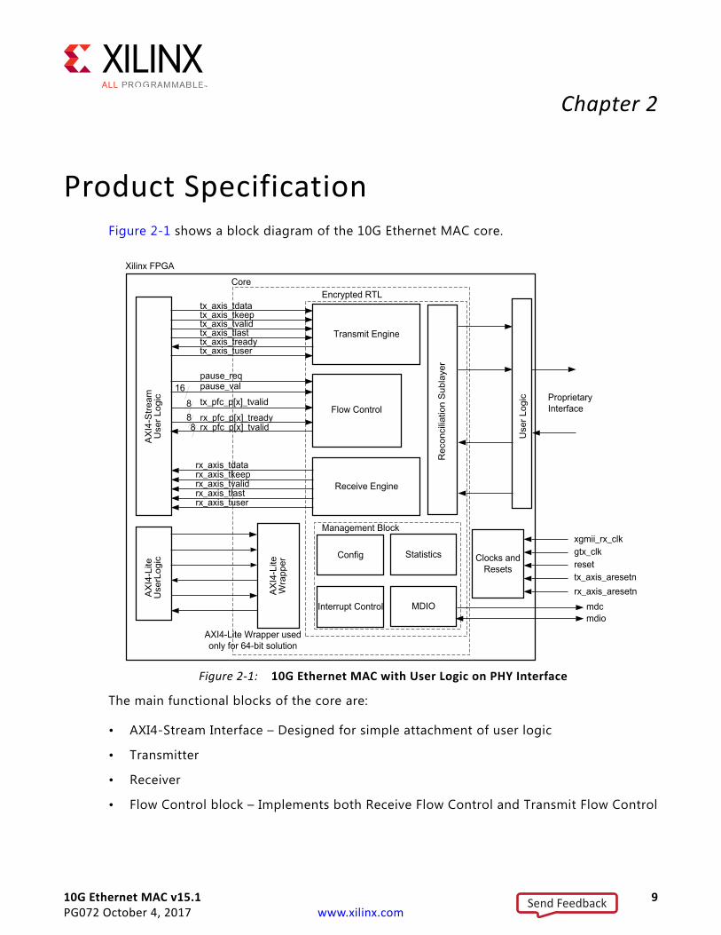
Product SpecificationFigure 2-1 shows a block diagram of the 10G Ethernet MAC core.
The main functional blocks of the core are:
• AXI4-Stream Interface – Designed for simple attachment of user logic
• Transmitter
• Receiver
• Flow Control block – Implements both Receive Flow Control and Transmit Flow Control
X-Ref Target - Figure 2-1
Figure 2-1: 10G Ethernet MAC with User Logic on PHY Interface
Send Feedback
10G Ethernet MAC v15.1 10PG072 October 4, 2017 www.xilinx.com
Chapter 2: Product Specification
• Reconciliation Sublayer (RS) – Processes XGMII Local Fault, Remote Fault and Link Interruption messages and handles DDR conversion
• AXI4-Lite Management interface and MDIO (optional)
• Statistics counters (optional)
• Proprietary (optional XGMII) interface – Connection to the physical layer device or logic
StandardsFor 10 Gb/s operation the core is designed to the IEEE Standard 802.3-2012 [Ref 1] 10 Gigabit Ethernet specification.
Supports IEEE 802.1Qbb priority-based flow control defined in IEEE Standard 802.1Qbb- Priority-based Flow Control [Ref 2].
PerformanceThis section details the performance information for various core configurations.
LatencyThese measurements are for the core only; they do not include the latency through the example design FIFO or IOB registers.
Transmit Path Latency
As measured from the input port tx_axis_tdata of the AXI4-Stream transmit interface (until that data appears on xgmii_txd on the PHY-side interface), the latency through the core with the 64-bit datapath option in the transmit direction is seven clock periods (or 44.8 ns) of the tx_clk0 at 156 MHz. The latency through the core when the 32-bit datapath option is selected is five clock periods (or 16 ns) of the tx_clk0 at 312 MHz.
Receive Path Latency
Measured from the xgmii_rxd port on the PHY-side receive interface (until the data appears on the rx_axis_tdata port of the receiver side AXI4-Stream interface), the latency through the core with the 64-bit datapath option in the receive direction is four clock periods (25.6 ns) of rx_clk0 at 156 MHz. This can increase to five clock periods (32 ns) if the core needs to modify the alignment of data at the AXI4-Stream receive interface. The latency through the core when the 32-bit datapath option is selected is 3 clock periods (or 9.6 ns) of the rx_clk0 at 312 MHz.
Send Feedback

10G Ethernet MAC v15.1 11PG072 October 4, 2017 www.xilinx.com
Chapter 2: Product Specification
Resource UtilizationFor details about resource utilization, visit Performance and Resource Utilization.
Port DescriptionsThis section describes the core ports.
AXI4-Stream Transmit InterfaceThe AXI4-Stream transmit interface signals are shown in Table 2-1. See Connecting the Data Interfaces for details on connecting to the transmit interface. When the 32-bit datapath option is selected the AXI4-Stream interface becomes 32-bits wide rather than 64.
AXI4-Stream Receive InterfaceThe AXI4-Stream receive interface signals are shown in Table 2-2. See Connecting the Data Interfaces for details on connecting to the receive interface. When the 32-bit datapath option is selected the AXI4-Stream interface becomes 32-bits wide rather than 64.
Table 2-1: AXI4-Stream Interface Ports – Transmit
Name Direction Description
tx_axis_aresetn In AXI4-Stream active-Low reset for transmit path
tx_axis_tdata[63 or 31:0] In AXI4-Stream data to core. Bus width depends on 64-bit or 32-bit selection.
tx_axis_tkeep[7 or 3:0] In AXI4-Stream data control to core. Bus width depends on 64-bit or 32-bit selection.
tx_axis_tvalid In AXI4-Stream data valid input to core
tx_axis_tuser[0:0] InAXI4-Stream user signal used to signal explicit underrun. This is a vector of length 1 rather than a single bit to allow for future expansion.
tx_ifg_delay[7:0] In Configures Interframe Gap adjustment between packets
tx_axis_tlast In AXI4-Stream signal to core indicating End of Ethernet Packet
tx_axis_tready Out AXI4-Stream acknowledge signal from core to indicate the start of a data transfer
Send Feedback
10G Ethernet MAC v15.1 12PG072 October 4, 2017 www.xilinx.com
Chapter 2: Product Specification
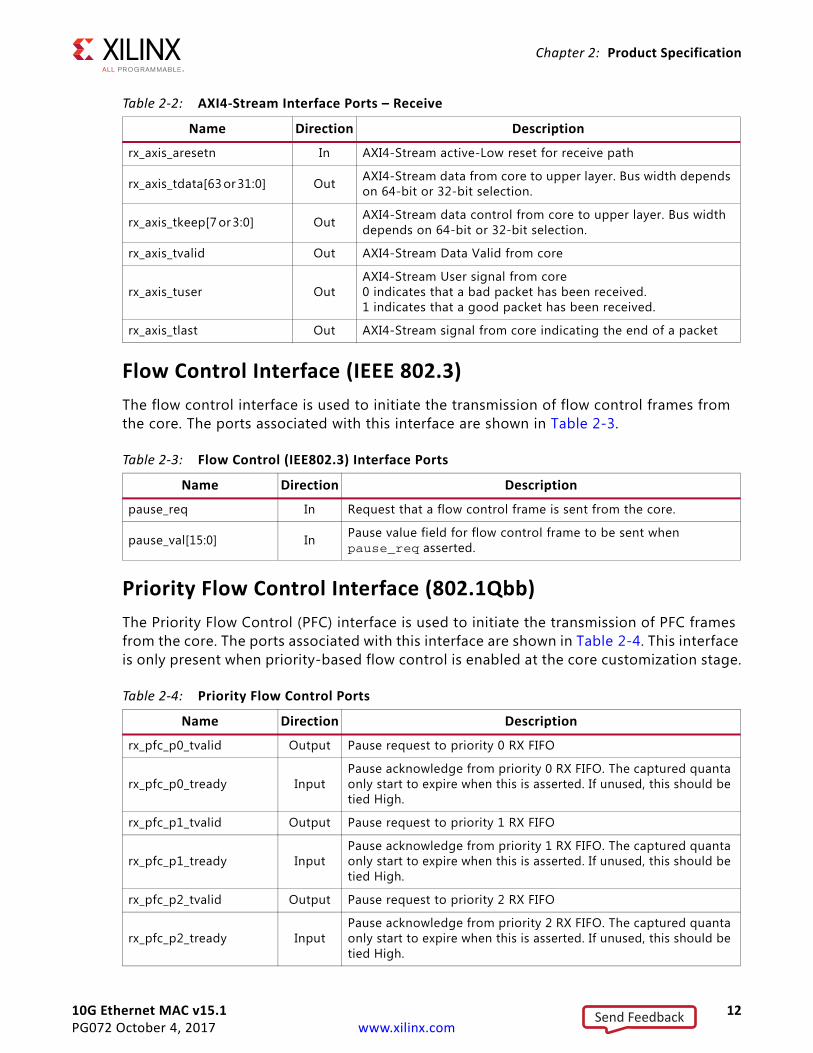
Flow Control Interface (IEEE 802.3)The flow control interface is used to initiate the transmission of flow control frames from the core. The ports associated with this interface are shown in Table 2-3.
Priority Flow Control Interface (802.1Qbb)The Priority Flow Control (PFC) interface is used to initiate the transmission of PFC frames from the core. The ports associated with this interface are shown in Table 2-4. This interface is only present when priority-based flow control is enabled at the core customization stage.
Table 2-2: AXI4-Stream Interface Ports – Receive
Name Direction Description
rx_axis_aresetn In AXI4-Stream active-Low reset for receive path
rx_axis_tdata[63 or 31:0] Out AXI4-Stream data from core to upper layer. Bus width depends on 64-bit or 32-bit selection.
rx_axis_tkeep[7 or 3:0] Out AXI4-Stream data control from core to upper layer. Bus width depends on 64-bit or 32-bit selection.
rx_axis_tvalid Out AXI4-Stream Data Valid from core
rx_axis_tuser OutAXI4-Stream User signal from core0 indicates that a bad packet has been received.1 indicates that a good packet has been received.
rx_axis_tlast Out AXI4-Stream signal from core indicating the end of a packet
Table 2-3: Flow Control (IEE802.3) Interface Ports
Name Direction Description
pause_req In Request that a flow control frame is sent from the core.
pause_val[15:0] In Pause value field for flow control frame to be sent when pause_req asserted.
Table 2-4: Priority Flow Control Ports
Name Direction Description
rx_pfc_p0_tvalid Output Pause request to priority 0 RX FIFO
rx_pfc_p0_tready InputPause acknowledge from priority 0 RX FIFO. The captured quanta only start to expire when this is asserted. If unused, this should be tied High.
rx_pfc_p1_tvalid Output Pause request to priority 1 RX FIFO
rx_pfc_p1_tready InputPause acknowledge from priority 1 RX FIFO. The captured quanta only start to expire when this is asserted. If unused, this should be tied High.
rx_pfc_p2_tvalid Output Pause request to priority 2 RX FIFO
rx_pfc_p2_tready InputPause acknowledge from priority 2 RX FIFO. The captured quanta only start to expire when this is asserted. If unused, this should be tied High.
Send Feedback
10G Ethernet MAC v15.1 13PG072 October 4, 2017 www.xilinx.com
Chapter 2: Product Specification
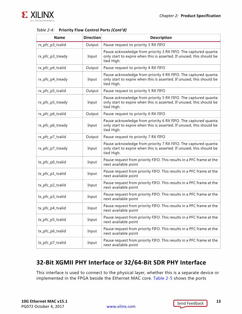
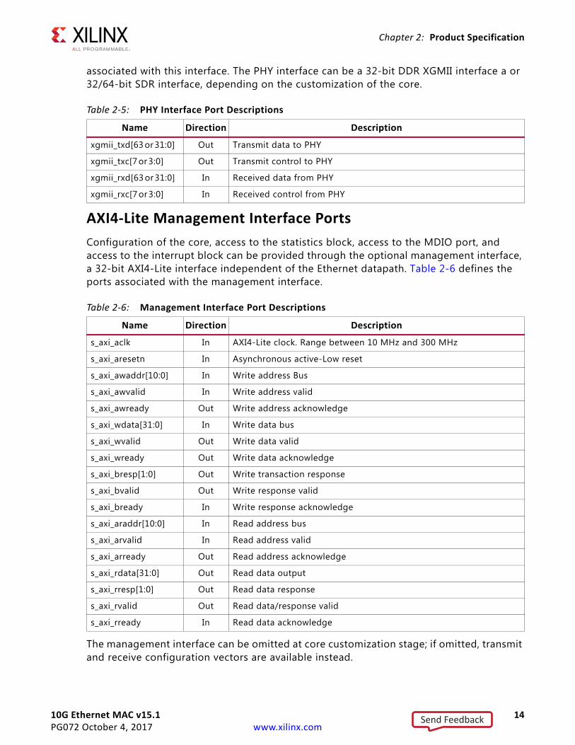
32-Bit XGMII PHY Interface or 32/64-Bit SDR PHY InterfaceThis interface is used to connect to the physical layer, whether this is a separate device or implemented in the FPGA beside the Ethernet MAC core. Table 2-5 shows the ports
rx_pfc_p3_tvalid Output Pause request to priority 3 RX FIFO
rx_pfc_p3_tready InputPause acknowledge from priority 3 RX FIFO. The captured quanta only start to expire when this is asserted. If unused, this should be tied High.
rx_pfc_p4_tvalid Output Pause request to priority 4 RX FIFO
rx_pfc_p4_tready InputPause acknowledge from priority 4 RX FIFO. The captured quanta only start to expire when this is asserted. If unused, this should be tied High.
rx_pfc_p5_tvalid Output Pause request to priority 5 RX FIFO
rx_pfc_p5_tready InputPause acknowledge from priority 5 RX FIFO. The captured quanta only start to expire when this is asserted. If unused, this should be tied High.
rx_pfc_p6_tvalid Output Pause request to priority 6 RX FIFO
rx_pfc_p6_tready InputPause acknowledge from priority 6 RX FIFO. The captured quanta only start to expire when this is asserted. If unused, this should be tied High.
rx_pfc_p7_tvalid Output Pause request to priority 7 RX FIFO
rx_pfc_p7_tready InputPause acknowledge from priority 7 RX FIFO. The captured quanta only start to expire when this is asserted. If unused, this should be tied High.
tx_pfc_p0_tvalid Input Pause request from priority FIFO. This results in a PFC frame at the next available point
tx_pfc_p1_tvalid Input Pause request from priority FIFO. This results in a PFC frame at the next available point
tx_pfc_p2_tvalid Input Pause request from priority FIFO. This results in a PFC frame at the next available point
tx_pfc_p3_tvalid Input Pause request from priority FIFO. This results in a PFC frame at the next available point
tx_pfc_p4_tvalid Input Pause request from priority FIFO. This results in a PFC frame at the next available point
tx_pfc_p5_tvalid Input Pause request from priority FIFO. This results in a PFC frame at the next available point
tx_pfc_p6_tvalid Input Pause request from priority FIFO. This results in a PFC frame at the next available point
tx_pfc_p7_tvalid Input Pause request from priority FIFO. This results in a PFC frame at the next available point
Table 2-4: Priority Flow Control Ports (Cont’d)
Name Direction Description
Send Feedback
10G Ethernet MAC v15.1 14PG072 October 4, 2017 www.xilinx.com
Chapter 2: Product Specification
associated with this interface. The PHY interface can be a 32-bit DDR XGMII interface a or 32/64-bit SDR interface, depending on the customization of the core.
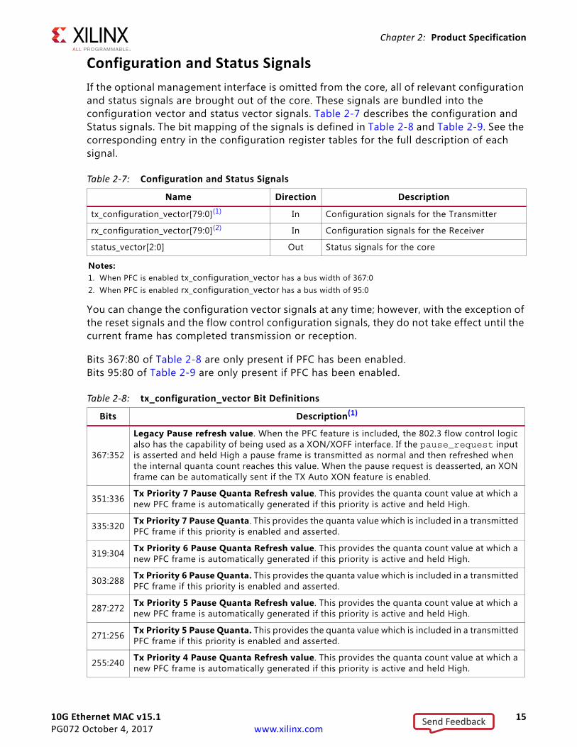
AXI4-Lite Management Interface PortsConfiguration of the core, access to the statistics block, access to the MDIO port, and access to the interrupt block can be provided through the optional management interface, a 32-bit AXI4-Lite interface independent of the Ethernet datapath. Table 2-6 defines the ports associated with the management interface.
The management interface can be omitted at core customization stage; if omitted, transmit and receive configuration vectors are available instead.
Table 2-5: PHY Interface Port Descriptions
Name Direction Description
xgmii_txd[63 or 31:0] Out Transmit data to PHY
xgmii_txc[7 or 3:0] Out Transmit control to PHY
xgmii_rxd[63 or 31:0] In Received data from PHY
xgmii_rxc[7 or 3:0] In Received control from PHY
Table 2-6: Management Interface Port Descriptions
Name Direction Description
s_axi_aclk In AXI4-Lite clock. Range between 10 MHz and 300 MHz
s_axi_aresetn In Asynchronous active-Low reset
s_axi_awaddr[10:0] In Write address Bus
s_axi_awvalid In Write address valid
s_axi_awready Out Write address acknowledge
s_axi_wdata[31:0] In Write data bus
s_axi_wvalid Out Write data valid
s_axi_wready Out Write data acknowledge
s_axi_bresp[1:0] Out Write transaction response
s_axi_bvalid Out Write response valid
s_axi_bready In Write response acknowledge
s_axi_araddr[10:0] In Read address bus
s_axi_arvalid In Read address valid
s_axi_arready Out Read address acknowledge
s_axi_rdata[31:0] Out Read data output
s_axi_rresp[1:0] Out Read data response
s_axi_rvalid Out Read data/response valid
s_axi_rready In Read data acknowledge
Send Feedback
10G Ethernet MAC v15.1 15PG072 October 4, 2017 www.xilinx.com
Chapter 2: Product Specification
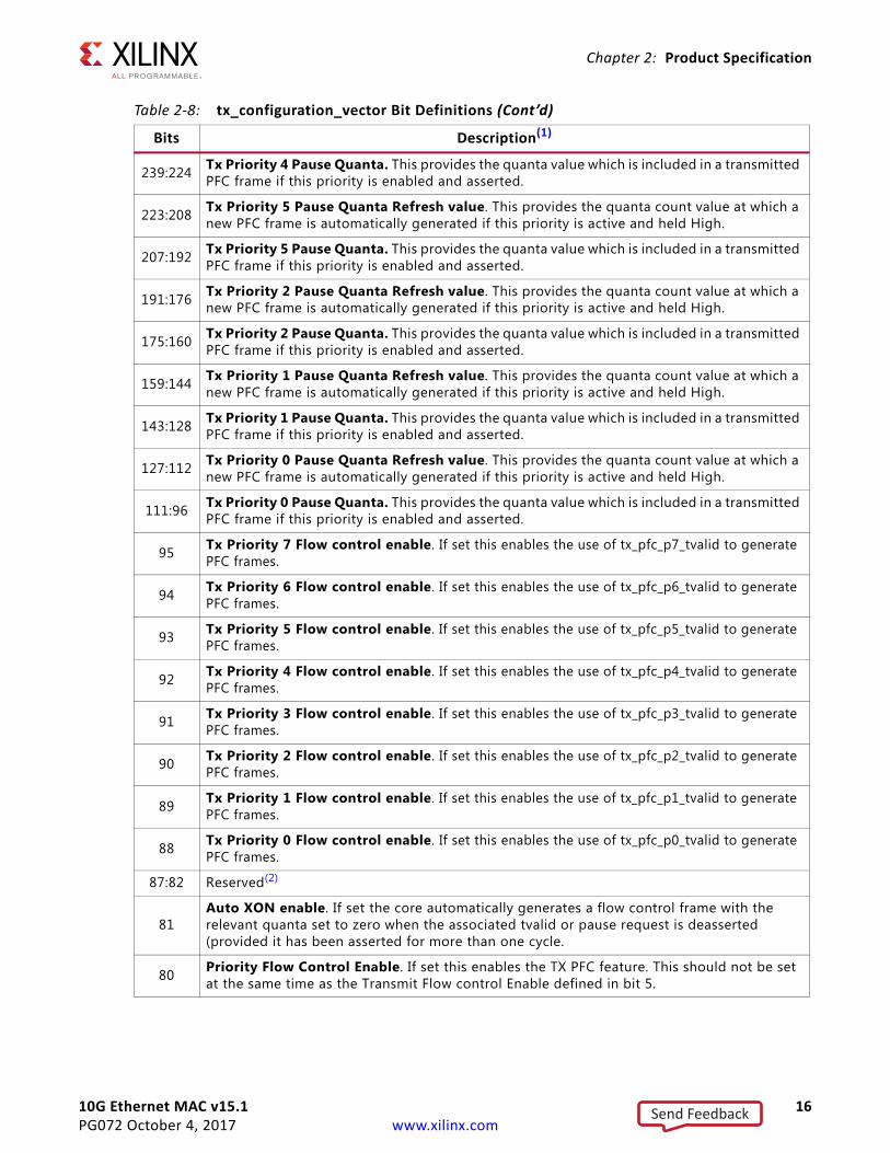
Configuration and Status SignalsIf the optional management interface is omitted from the core, all of relevant configuration and status signals are brought out of the core. These signals are bundled into the configuration vector and status vector signals. Table 2-7 describes the configuration and Status signals. The bit mapping of the signals is defined in Table 2-8 and Table 2-9. See the corresponding entry in the configuration register tables for the full description of each signal.
You can change the configuration vector signals at any time; however, with the exception of the reset signals and the flow control configuration signals, they do not take effect until the current frame has completed transmission or reception.
Bits 367:80 of Table 2-8 are only present if PFC has been enabled. Bits 95:80 of Table 2-9 are only present if PFC has been enabled.
Table 2-7: Configuration and Status Signals
Name Direction Description
tx_configuration_vector[79:0](1) In Configuration signals for the Transmitter
rx_configuration_vector[79:0](2) In Configuration signals for the Receiver
status_vector[2:0] Out Status signals for the core
Notes: 1. When PFC is enabled tx_configuration_vector has a bus width of 367:02. When PFC is enabled rx_configuration_vector has a bus width of 95:0
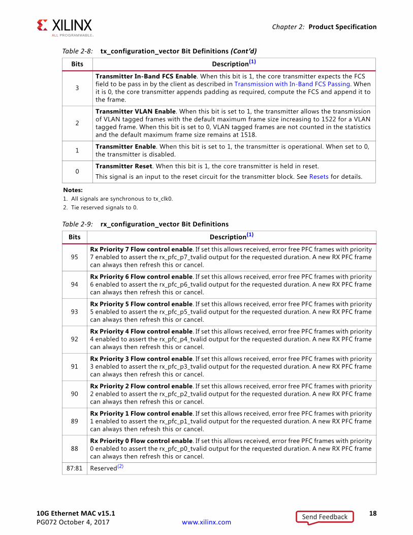
Table 2-8: tx_configuration_vector Bit Definitions
Bits Description(1)
367:352
Legacy Pause refresh value. When the PFC feature is included, the 802.3 flow control logic also has the capability of being used as a XON/XOFF interface. If the pause_request input is asserted and held High a pause frame is transmitted as normal and then refreshed when the internal quanta count reaches this value. When the pause request is deasserted, an XON frame can be automatically sent if the TX Auto XON feature is enabled.
351:336 Tx Priority 7 Pause Quanta Refresh value. This provides the quanta count value at which a new PFC frame is automatically generated if this priority is active and held High.
335:320 Tx Priority 7 Pause Quanta. This provides the quanta value which is included in a transmitted PFC frame if this priority is enabled and asserted.
319:304 Tx Priority 6 Pause Quanta Refresh value. This provides the quanta count value at which a new PFC frame is automatically generated if this priority is active and held High.
303:288 Tx Priority 6 Pause Quanta. This provides the quanta value which is included in a transmitted PFC frame if this priority is enabled and asserted.
287:272 Tx Priority 5 Pause Quanta Refresh value. This provides the quanta count value at which a new PFC frame is automatically generated if this priority is active and held High.
271:256 Tx Priority 5 Pause Quanta. This provides the quanta value which is included in a transmitted PFC frame if this priority is enabled and asserted.
255:240 Tx Priority 4 Pause Quanta Refresh value. This provides the quanta count value at which a new PFC frame is automatically generated if this priority is active and held High.
Send Feedback
10G Ethernet MAC v15.1 16PG072 October 4, 2017 www.xilinx.com
Chapter 2: Product Specification
239:224 Tx Priority 4 Pause Quanta. This provides the quanta value which is included in a transmitted PFC frame if this priority is enabled and asserted.
223:208 Tx Priority 5 Pause Quanta Refresh value. This provides the quanta count value at which a new PFC frame is automatically generated if this priority is active and held High.
207:192 Tx Priority 5 Pause Quanta. This provides the quanta value which is included in a transmitted PFC frame if this priority is enabled and asserted.
191:176 Tx Priority 2 Pause Quanta Refresh value. This provides the quanta count value at which a new PFC frame is automatically generated if this priority is active and held High.
175:160 Tx Priority 2 Pause Quanta. This provides the quanta value which is included in a transmitted PFC frame if this priority is enabled and asserted.
159:144 Tx Priority 1 Pause Quanta Refresh value. This provides the quanta count value at which a new PFC frame is automatically generated if this priority is active and held High.
143:128 Tx Priority 1 Pause Quanta. This provides the quanta value which is included in a transmitted PFC frame if this priority is enabled and asserted.
127:112 Tx Priority 0 Pause Quanta Refresh value. This provides the quanta count value at which a new PFC frame is automatically generated if this priority is active and held High.
111:96 Tx Priority 0 Pause Quanta. This provides the quanta value which is included in a transmitted PFC frame if this priority is enabled and asserted.
95 Tx Priority 7 Flow control enable. If set this enables the use of tx_pfc_p7_tvalid to generate PFC frames.
94 Tx Priority 6 Flow control enable. If set this enables the use of tx_pfc_p6_tvalid to generate PFC frames.
93 Tx Priority 5 Flow control enable. If set this enables the use of tx_pfc_p5_tvalid to generate PFC frames.
92 Tx Priority 4 Flow control enable. If set this enables the use of tx_pfc_p4_tvalid to generate PFC frames.
91 Tx Priority 3 Flow control enable. If set this enables the use of tx_pfc_p3_tvalid to generate PFC frames.
90 Tx Priority 2 Flow control enable. If set this enables the use of tx_pfc_p2_tvalid to generate PFC frames.
89 Tx Priority 1 Flow control enable. If set this enables the use of tx_pfc_p1_tvalid to generate PFC frames.
88 Tx Priority 0 Flow control enable. If set this enables the use of tx_pfc_p0_tvalid to generate PFC frames.
87:82 Reserved(2)
81Auto XON enable. If set the core automatically generates a flow control frame with the relevant quanta set to zero when the associated tvalid or pause request is deasserted (provided it has been asserted for more than one cycle.
80 Priority Flow Control Enable. If set this enables the TX PFC feature. This should not be set at the same time as the Transmit Flow control Enable defined in bit 5.
Table 2-8: tx_configuration_vector Bit Definitions (Cont’d)
Bits Description(1)
Send Feedback
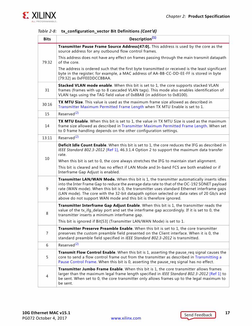
10G Ethernet MAC v15.1 17PG072 October 4, 2017 www.xilinx.com
Chapter 2: Product Specification
79:32
Transmitter Pause Frame Source Address[47:0]. This address is used by the core as the source address for any outbound flow control frames.
This address does not have any effect on frames passing through the main transmit datapath of the core.
The address is ordered such that the first byte transmitted or received is the least significant byte in the register; for example, a MAC address of AA-BB-CC-DD-EE-FF is stored in byte [79:32] as 0xFFEEDDCCBBAA.
31Stacked VLAN mode enable. When this bit is set to 1, the core supports stacked VLAN frames (frames with up to 8 cascaded VLAN tags). This mode also enables identification of VLAN tags using the TAG field value of 0x88A8 (in addition to 0x8100).
30:16 TX MTU Size. This value is used as the maximum frame size allowed as described in Transmitter Maximum Permitted Frame Length when TX MTU Enable is set to 1.
15 Reserved(2)
14TX MTU Enable. When this bit is set to 1, the value in TX MTU Size is used as the maximum frame size allowed as described in Transmitter Maximum Permitted Frame Length. When set to 0 frame handling depends on the other configuration settings.
13:11 Reserved(2)
10
Deficit Idle Count Enable. When this bit is set to 1, the core reduces the IFG as described in IEEE Standard 802.3-2012 [Ref 1], 46.3.1.4 Option 2 to support the maximum data transfer rate.
When this bit is set to 0, the core always stretches the IFG to maintain start alignment.
This bit is cleared and has no effect if LAN Mode and In-band FCS are both enabled or if Interframe Gap Adjust is enabled.
9
Transmitter LAN/WAN Mode. When this bit is 1, the transmitter automatically inserts idles into the Inter Frame Gap to reduce the average data rate to that of the OC-192 SONET payload rate (WAN mode). When this bit is 0, the transmitter uses standard Ethernet interframe gaps (LAN mode). The core with the 32-bit datapath option selected or data rates of 20 Gb/s and above do not support WAN mode and this bit is therefore ignored.
8
Transmitter Interframe Gap Adjust Enable. When this bit is 1, the transmitter reads the value of the tx_ifg_delay port and set the interframe gap accordingly. If it is set to 0, the transmitter inserts a minimum interframe gap.
This bit is ignored if Bit[53] (Transmitter LAN/WAN Mode) is set to 1.
7Transmitter Preserve Preamble Enable. When this bit is set to 1, the core transmitter preserves the custom preamble field presented on the Client interface. When it is 0, the standard preamble field specified in IEEE Standard 802.3-2012 is transmitted.
6 Reserved(2)
5Transmit Flow Control Enable. When this bit is 1, asserting the pause_req signal causes the core to send a flow control frame out from the transmitter as described in Transmitting a Pause Control Frame. When this bit is 0, asserting the pause_req signal has no effect.
4
Transmitter Jumbo Frame Enable. When this bit is 1, the core transmitter allows frames larger than the maximum legal frame length specified in IEEE Standard 802.3-2012 [Ref 1] to be sent. When set to 0, the core transmitter only allows frames up to the legal maximum to be sent.
Table 2-8: tx_configuration_vector Bit Definitions (Cont’d)
Bits Description(1)
Send Feedback
10G Ethernet MAC v15.1 18PG072 October 4, 2017 www.xilinx.com
Chapter 2: Product Specification
3
Transmitter In-Band FCS Enable. When this bit is 1, the core transmitter expects the FCS field to be pass in by the client as described in Transmission with In-Band FCS Passing. When it is 0, the core transmitter appends padding as required, compute the FCS and append it to the frame.
2
Transmitter VLAN Enable. When this bit is set to 1, the transmitter allows the transmission of VLAN tagged frames with the default maximum frame size increasing to 1522 for a VLAN tagged frame. When this bit is set to 0, VLAN tagged frames are not counted in the statistics and the default maximum frame size remains at 1518.
1 Transmitter Enable. When this bit is set to 1, the transmitter is operational. When set to 0, the transmitter is disabled.
0Transmitter Reset. When this bit is 1, the core transmitter is held in reset.
This signal is an input to the reset circuit for the transmitter block. See Resets for details.
Notes: 1. All signals are synchronous to tx_clk0.2. Tie reserved signals to 0.
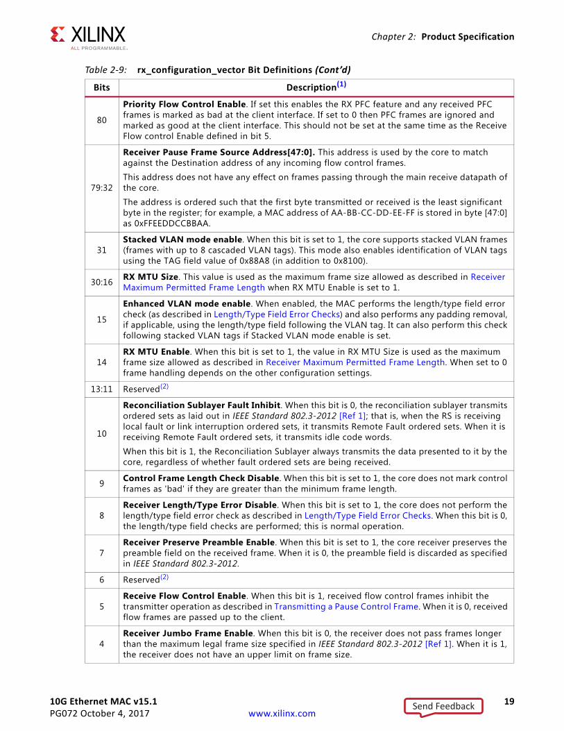
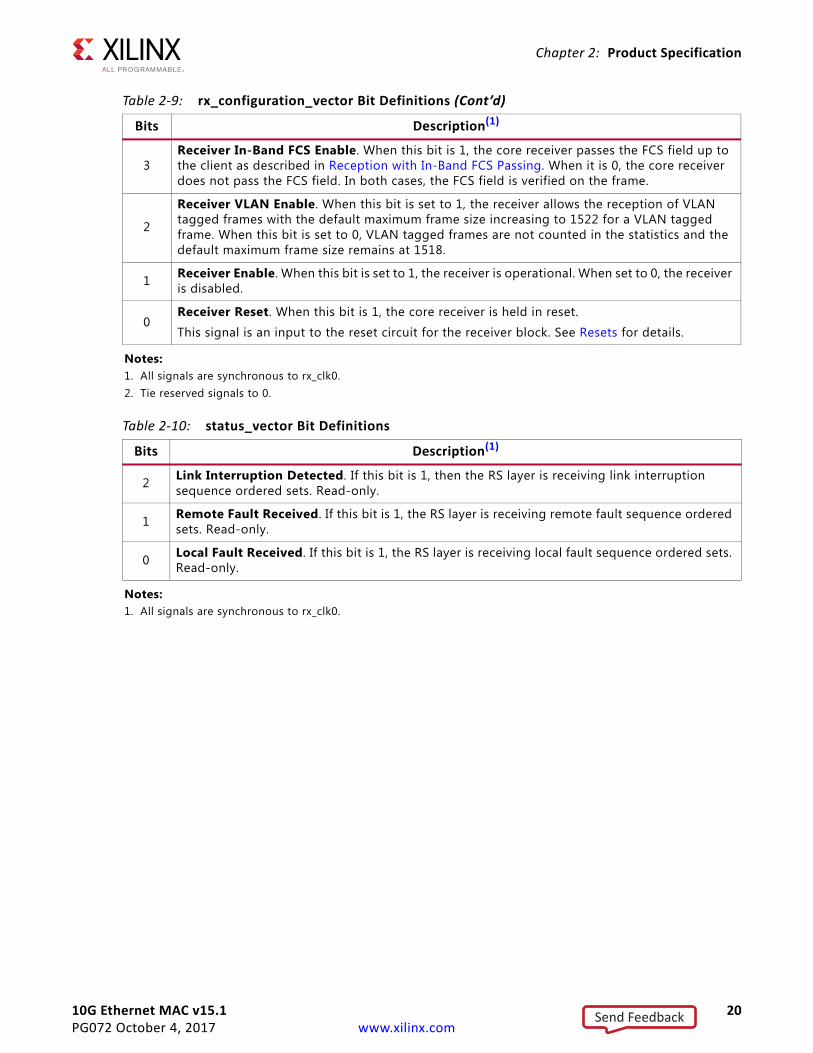
Table 2-9: rx_configuration_vector Bit Definitions
Bits Description(1)
95Rx Priority 7 Flow control enable. If set this allows received, error free PFC frames with priority 7 enabled to assert the rx_pfc_p7_tvalid output for the requested duration. A new RX PFC frame can always then refresh this or cancel.
94Rx Priority 6 Flow control enable. If set this allows received, error free PFC frames with priority 6 enabled to assert the rx_pfc_p6_tvalid output for the requested duration. A new RX PFC frame can always then refresh this or cancel.
93Rx Priority 5 Flow control enable. If set this allows received, error free PFC frames with priority 5 enabled to assert the rx_pfc_p5_tvalid output for the requested duration. A new RX PFC frame can always then refresh this or cancel.
92Rx Priority 4 Flow control enable. If set this allows received, error free PFC frames with priority 4 enabled to assert the rx_pfc_p4_tvalid output for the requested duration. A new RX PFC frame can always then refresh this or cancel.
91Rx Priority 3 Flow control enable. If set this allows received, error free PFC frames with priority 3 enabled to assert the rx_pfc_p3_tvalid output for the requested duration. A new RX PFC frame can always then refresh this or cancel.
90Rx Priority 2 Flow control enable. If set this allows received, error free PFC frames with priority 2 enabled to assert the rx_pfc_p2_tvalid output for the requested duration. A new RX PFC frame can always then refresh this or cancel.
89Rx Priority 1 Flow control enable. If set this allows received, error free PFC frames with priority 1 enabled to assert the rx_pfc_p1_tvalid output for the requested duration. A new RX PFC frame can always then refresh this or cancel.
88Rx Priority 0 Flow control enable. If set this allows received, error free PFC frames with priority 0 enabled to assert the rx_pfc_p0_tvalid output for the requested duration. A new RX PFC frame can always then refresh this or cancel.
87:81 Reserved(2)
Table 2-8: tx_configuration_vector Bit Definitions (Cont’d)
Bits Description(1)
Send Feedback
10G Ethernet MAC v15.1 19PG072 October 4, 2017 www.xilinx.com
Chapter 2: Product Specification
80
Priority Flow Control Enable. If set this enables the RX PFC feature and any received PFC frames is marked as bad at the client interface. If set to 0 then PFC frames are ignored and marked as good at the client interface. This should not be set at the same time as the Receive Flow control Enable defined in bit 5.
79:32
Receiver Pause Frame Source Address[47:0]. This address is used by the core to match against the Destination address of any incoming flow control frames.
This address does not have any effect on frames passing through the main receive datapath of the core.
The address is ordered such that the first byte transmitted or received is the least significant byte in the register; for example, a MAC address of AA-BB-CC-DD-EE-FF is stored in byte [47:0] as 0xFFEEDDCCBBAA.
31Stacked VLAN mode enable. When this bit is set to 1, the core supports stacked VLAN frames (frames with up to 8 cascaded VLAN tags). This mode also enables identification of VLAN tags using the TAG field value of 0x88A8 (in addition to 0x8100).
30:16 RX MTU Size. This value is used as the maximum frame size allowed as described in Receiver Maximum Permitted Frame Length when RX MTU Enable is set to 1.
15
Enhanced VLAN mode enable. When enabled, the MAC performs the length/type field error check (as described in Length/Type Field Error Checks) and also performs any padding removal, if applicable, using the length/type field following the VLAN tag. It can also perform this check following stacked VLAN tags if Stacked VLAN mode enable is set.
14RX MTU Enable. When this bit is set to 1, the value in RX MTU Size is used as the maximum frame size allowed as described in Receiver Maximum Permitted Frame Length. When set to 0 frame handling depends on the other configuration settings.
13:11 Reserved(2)
10
Reconciliation Sublayer Fault Inhibit. When this bit is 0, the reconciliation sublayer transmits ordered sets as laid out in IEEE Standard 802.3-2012 [Ref 1]; that is, when the RS is receiving local fault or link interruption ordered sets, it transmits Remote Fault ordered sets. When it is receiving Remote Fault ordered sets, it transmits idle code words.
When this bit is 1, the Reconciliation Sublayer always transmits the data presented to it by the core, regardless of whether fault ordered sets are being received.
9 Control Frame Length Check Disable. When this bit is set to 1, the core does not mark control frames as 'bad' if they are greater than the minimum frame length.
8Receiver Length/Type Error Disable. When this bit is set to 1, the core does not perform the length/type field error check as described in Length/Type Field Error Checks. When this bit is 0, the length/type field checks are performed; this is normal operation.
7Receiver Preserve Preamble Enable. When this bit is set to 1, the core receiver preserves the preamble field on the received frame. When it is 0, the preamble field is discarded as specified in IEEE Standard 802.3-2012.
6 Reserved(2)
5Receive Flow Control Enable. When this bit is 1, received flow control frames inhibit the transmitter operation as described in Transmitting a Pause Control Frame. When it is 0, received flow frames are passed up to the client.
4Receiver Jumbo Frame Enable. When this bit is 0, the receiver does not pass frames longer than the maximum legal frame size specified in IEEE Standard 802.3-2012 [Ref 1]. When it is 1, the receiver does not have an upper limit on frame size.
Table 2-9: rx_configuration_vector Bit Definitions (Cont’d)
Bits Description(1)
Send Feedback
10G Ethernet MAC v15.1 20PG072 October 4, 2017 www.xilinx.com
Chapter 2: Product Specification
3Receiver In-Band FCS Enable. When this bit is 1, the core receiver passes the FCS field up to the client as described in Reception with In-Band FCS Passing. When it is 0, the core receiver does not pass the FCS field. In both cases, the FCS field is verified on the frame.
2
Receiver VLAN Enable. When this bit is set to 1, the receiver allows the reception of VLAN tagged frames with the default maximum frame size increasing to 1522 for a VLAN tagged frame. When this bit is set to 0, VLAN tagged frames are not counted in the statistics and the default maximum frame size remains at 1518.
1 Receiver Enable. When this bit is set to 1, the receiver is operational. When set to 0, the receiver is disabled.
0Receiver Reset. When this bit is 1, the core receiver is held in reset.
This signal is an input to the reset circuit for the receiver block. See Resets for details.
Notes: 1. All signals are synchronous to rx_clk0.2. Tie reserved signals to 0.
Table 2-10: status_vector Bit Definitions
Bits Description(1)
2 Link Interruption Detected. If this bit is 1, then the RS layer is receiving link interruption sequence ordered sets. Read-only.
1 Remote Fault Received. If this bit is 1, the RS layer is receiving remote fault sequence ordered sets. Read-only.
0 Local Fault Received. If this bit is 1, the RS layer is receiving local fault sequence ordered sets. Read-only.
Notes: 1. All signals are synchronous to rx_clk0.
Table 2-9: rx_configuration_vector Bit Definitions (Cont’d)
Bits Description(1)
Send Feedback
10G Ethernet MAC v15.1 21PG072 October 4, 2017 www.xilinx.com
Chapter 2: Product Specification
Statistics Vector SignalsIn addition to the statistics counters described in Statistics Counters, there are two statistics vector outputs on the core that are used to signal the core state. The signals are shown in Table 2-11.
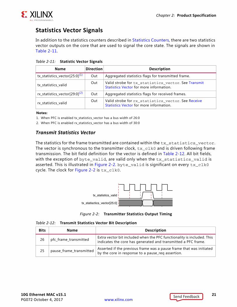
Transmit Statistics Vector
The statistics for the frame transmitted are contained within the tx_statistics_vector. The vector is synchronous to the transmitter clock, tx_clk0 and is driven following frame transmission. The bit field definition for the vector is defined in Table 2-12. All bit fields, with the exception of byte_valid, are valid only when the tx_statistics_valid is asserted. This is illustrated in Figure 2-2. byte_valid is significant on every tx_clk0 cycle. The clock for Figure 2-2 is tx_clk0.
Table 2-11: Statistic Vector Signals
Name Direction Description
tx_statistics_vector[25:0](1) Out Aggregated statistics flags for transmitted frame.
tx_statistics_valid Out Valid strobe for tx_statistics_vector. See Transmit Statistics Vector for more information.
rx_statistics_vector[29:0](2) Out Aggregated statistics flags for received frames.
rx_statistics_valid Out Valid strobe for rx_statistics_vector. See Receive Statistics Vector for more information.
Notes: 1. When PFC is enabled tx_statistics_vector has a bus width of 26:02. When PFC is enabled rx_statistics_vector has a bus width of 30:0
X-Ref Target - Figure 2-2
Figure 2-2: Transmitter Statistics Output Timing
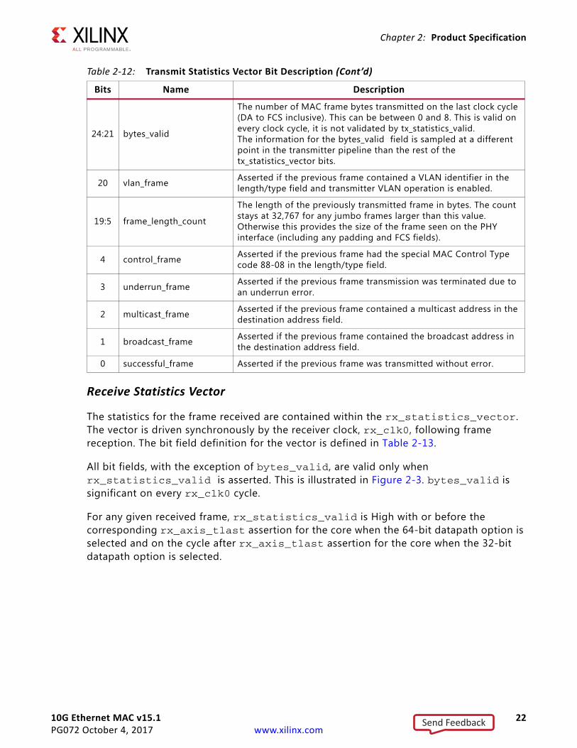
Table 2-12: Transmit Statistics Vector Bit Description
Bits Name Description
26 pfc_frame_transmitted Extra vector bit included when the PFC functionality is included. This indicates the core has generated and transmitted a PFC frame.
25 pause_frame_transmitted Asserted if the previous frame was a pause frame that was initiated by the core in response to a pause_req assertion.
Send Feedback
10G Ethernet MAC v15.1 22PG072 October 4, 2017 www.xilinx.com
Chapter 2: Product Specification
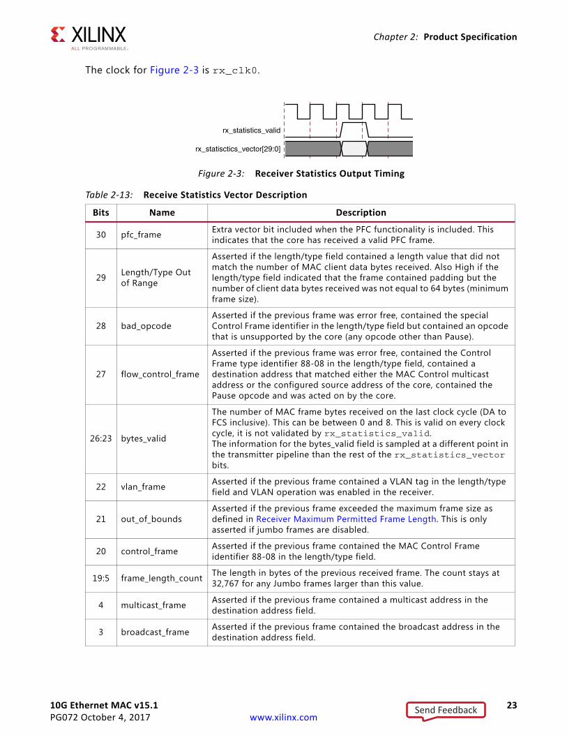
Receive Statistics Vector
The statistics for the frame received are contained within the rx_statistics_vector. The vector is driven synchronously by the receiver clock, rx_clk0, following frame reception. The bit field definition for the vector is defined in Table 2-13.
All bit fields, with the exception of bytes_valid, are valid only when rx_statistics_valid is asserted. This is illustrated in Figure 2-3. bytes_valid is significant on every rx_clk0 cycle.
For any given received frame, rx_statistics_valid is High with or before the corresponding rx_axis_tlast assertion for the core when the 64-bit datapath option is selected and on the cycle after rx_axis_tlast assertion for the core when the 32-bit datapath option is selected.
24:21 bytes_valid
The number of MAC frame bytes transmitted on the last clock cycle (DA to FCS inclusive). This can be between 0 and 8. This is valid on every clock cycle, it is not validated by tx_statistics_valid.The information for the bytes_valid field is sampled at a different point in the transmitter pipeline than the rest of the tx_statistics_vector bits.
20 vlan_frame Asserted if the previous frame contained a VLAN identifier in the length/type field and transmitter VLAN operation is enabled.
19:5 frame_length_count
The length of the previously transmitted frame in bytes. The count stays at 32,767 for any jumbo frames larger than this value. Otherwise this provides the size of the frame seen on the PHY interface (including any padding and FCS fields).
4 control_frame Asserted if the previous frame had the special MAC Control Type code 88-08 in the length/type field.
3 underrun_frame Asserted if the previous frame transmission was terminated due to an underrun error.
2 multicast_frame Asserted if the previous frame contained a multicast address in the destination address field.
1 broadcast_frame Asserted if the previous frame contained the broadcast address in the destination address field.
0 successful_frame Asserted if the previous frame was transmitted without error.
Table 2-12: Transmit Statistics Vector Bit Description (Cont’d)
Bits Name Description
Send Feedback
10G Ethernet MAC v15.1 23PG072 October 4, 2017 www.xilinx.com
Chapter 2: Product Specification
The clock for Figure 2-3 is rx_clk0.
X-Ref Target - Figure 2-3
Figure 2-3: Receiver Statistics Output Timing
Table 2-13: Receive Statistics Vector Description
Bits Name Description
30 pfc_frame Extra vector bit included when the PFC functionality is included. This indicates that the core has received a valid PFC frame.
29 Length/Type Outof Range
Asserted if the length/type field contained a length value that did not match the number of MAC client data bytes received. Also High if the length/type field indicated that the frame contained padding but the number of client data bytes received was not equal to 64 bytes (minimum frame size).
28 bad_opcodeAsserted if the previous frame was error free, contained the special Control Frame identifier in the length/type field but contained an opcode that is unsupported by the core (any opcode other than Pause).
27 flow_control_frame
Asserted if the previous frame was error free, contained the Control Frame type identifier 88-08 in the length/type field, contained a destination address that matched either the MAC Control multicast address or the configured source address of the core, contained the Pause opcode and was acted on by the core.
26:23 bytes_valid
The number of MAC frame bytes received on the last clock cycle (DA to FCS inclusive). This can be between 0 and 8. This is valid on every clock cycle, it is not validated by rx_statistics_valid.The information for the bytes_valid field is sampled at a different point in the transmitter pipeline than the rest of the rx_statistics_vector bits.
22 vlan_frame Asserted if the previous frame contained a VLAN tag in the length/type field and VLAN operation was enabled in the receiver.
21 out_of_boundsAsserted if the previous frame exceeded the maximum frame size as defined in Receiver Maximum Permitted Frame Length. This is only asserted if jumbo frames are disabled.
20 control_frame Asserted if the previous frame contained the MAC Control Frame identifier 88-08 in the length/type field.
19:5 frame_length_count The length in bytes of the previous received frame. The count stays at 32,767 for any Jumbo frames larger than this value.
4 multicast_frame Asserted if the previous frame contained a multicast address in the destination address field.
3 broadcast_frame Asserted if the previous frame contained the broadcast address in the destination address field.
Send Feedback
10G Ethernet MAC v15.1 24PG072 October 4, 2017 www.xilinx.com
Chapter 2: Product Specification
MDIO Interface SignalsThe MDIO interface signals are shown in Table 2-14. See Connecting the Management Interface for details.
Interrupt SignalThe Interrupt output signal is shown in Table 2-15. See Interrupt Output Registers for more details.
Clock and Reset SignalsIncluded in the example design top-level sources are circuits for clock and reset management. These can include Mixed-Mode Clock Managers (MMCMs), clock buffers, and reset synchronizers.
Table 2-16 through Table 2-18 show the clock, clock management, and reset signal ports on the various interfaces.
2 fcs_error Asserted if the previous frame received had an incorrect FCS value or the core detected error codes during frame reception.
1 bad_frame Asserted if the previous frame received contained errors.
0 good_frame Asserted if the previous frame received was error free.
Table 2-14: MDIO Interface Port Descriptions
Name Direction Description
mdc Out MDIO clock
mdio_in In MDIO input
mdio_out Out MDIO output
mdio_tri Out MDIO 3-state. A 1 disconnects the output driver from the MDIO bus.
Table 2-15: Interrupt Output Port Description
Name Direction Description
xgmacint Out Interrupt output.
Table 2-16: Internal Physical Interface
Name Direction Description
reset In Set to 1 to reset core. Treated as an asynchronous input by the core.
tx_clk0 In System clock for transmit side of core; derived from gtx_clk in example design.
tx_dcm_locked In Status flag from DCM/MMCM.
Table 2-13: Receive Statistics Vector Description (Cont’d)
Bits Name Description
Send Feedback
10G Ethernet MAC v15.1 25PG072 October 4, 2017 www.xilinx.com
Chapter 2: Product Specification
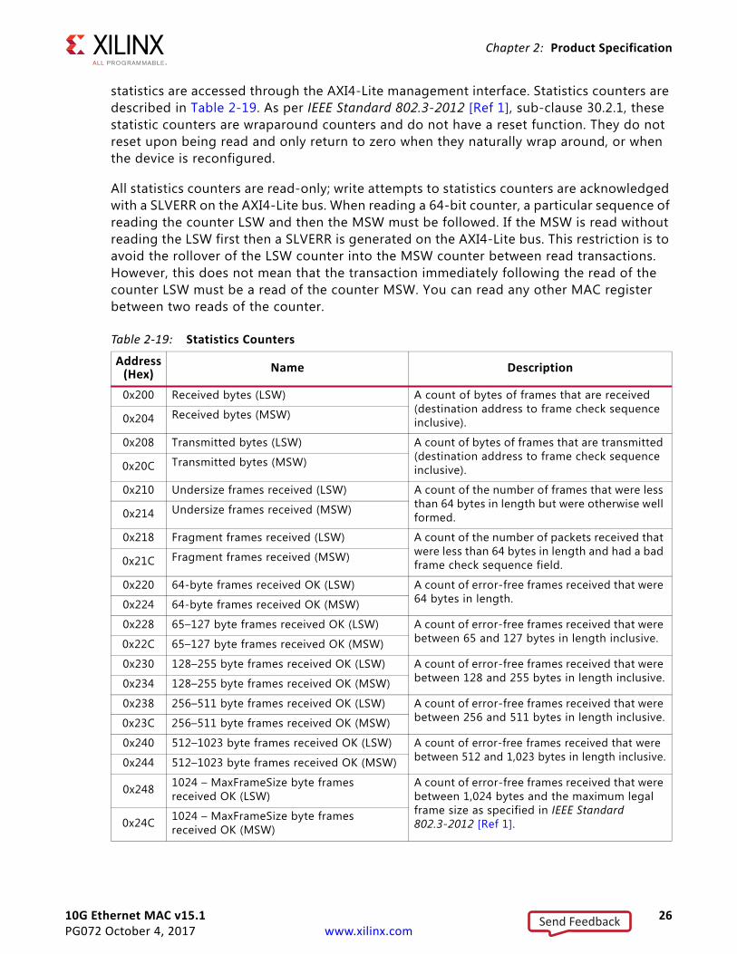
Register SpaceStatistics CountersDuring operation, the core collects statistics on the success and failure of various operations for processing by network management entities elsewhere in the system. These
rx_clk0 In System clock for receive side of core; derived from xgmii_rx_clk in example design.
rx_dcm_locked In Status flag from DCM/MMCM.
Table 2-17: External XGMII Interface with Shared Logic in Example Design
Name Direction Description
reset In Set to 1 to reset core. Treated as an asynchronous input by the core.
tx_clk0 In System clock for transmit side of core, derived from gtx_clk in example design.
tx_clk90 In 90° phase shift of system clock, derived from gtx_clk in example design.
tx_dcm_locked In Status flag from DCM/MMCM.
xgmii_tx_clk Out XGMII ODDR output clock sent to external PHY.
xgmii_rx_clk In Received clock from the connected PHY.
rx_clk_out Out System clock for the receive logic.
rx_dcm_locked_out Out Status signal from clock management block in core that performs clock/data alignment on the receive path.
Table 2-18: External XGMII Interface with Shared Logic in Core
Name Direction Descriptionreset In Set to 1 to reset core. Treated as an asynchronous input by the core.
gtx_clk In 156.25 MHz system clock input.
tx_clk0_out Out System clock for transmit side of core, derived from gtx_clk input.
tx_clk90_out Out 90° phase shift of transmit system clock, derived from gtx_clk input.
tx_dcm_locked_out Out Status flag from DCM/MMCM.
xgmii_tx_clk Out XGMII ODDR output clock sent to external PHY.
xgmii_rx_clk In Received clock from the connected PHY.
rx_clk_out Out System clock for the receive logic.
rx_dcm_locked_out Out Status signal from clock management block in core that performs clock/data alignment on the receive path.
Table 2-16: Internal Physical Interface (Cont’d)
Name Direction Description
Send Feedback
10G Ethernet MAC v15.1 26PG072 October 4, 2017 www.xilinx.com
Chapter 2: Product Specification
statistics are accessed through the AXI4-Lite management interface. Statistics counters are described in Table 2-19. As per IEEE Standard 802.3-2012 [Ref 1], sub-clause 30.2.1, these statistic counters are wraparound counters and do not have a reset function. They do not reset upon being read and only return to zero when they naturally wrap around, or when the device is reconfigured.
All statistics counters are read-only; write attempts to statistics counters are acknowledged with a SLVERR on the AXI4-Lite bus. When reading a 64-bit counter, a particular sequence of reading the counter LSW and then the MSW must be followed. If the MSW is read without reading the LSW first then a SLVERR is generated on the AXI4-Lite bus. This restriction is to avoid the rollover of the LSW counter into the MSW counter between read transactions. However, this does not mean that the transaction immediately following the read of the counter LSW must be a read of the counter MSW. You can read any other MAC register between two reads of the counter.
Table 2-19: Statistics Counters
Address(Hex) Name Description
0x200 Received bytes (LSW) A count of bytes of frames that are received (destination address to frame check sequence inclusive).0x204 Received bytes (MSW)
0x208 Transmitted bytes (LSW) A count of bytes of frames that are transmitted (destination address to frame check sequence inclusive).0x20C Transmitted bytes (MSW)
0x210 Undersize frames received (LSW) A count of the number of frames that were less than 64 bytes in length but were otherwise well formed.0x214 Undersize frames received (MSW)
0x218 Fragment frames received (LSW) A count of the number of packets received that were less than 64 bytes in length and had a bad frame check sequence field.0x21C Fragment frames received (MSW)
0x220 64-byte frames received OK (LSW) A count of error-free frames received that were 64 bytes in length.0x224 64-byte frames received OK (MSW)
0x228 65–127 byte frames received OK (LSW) A count of error-free frames received that were between 65 and 127 bytes in length inclusive.0x22C 65–127 byte frames received OK (MSW)
0x230 128–255 byte frames received OK (LSW) A count of error-free frames received that were between 128 and 255 bytes in length inclusive.0x234 128–255 byte frames received OK (MSW)
0x238 256–511 byte frames received OK (LSW) A count of error-free frames received that were between 256 and 511 bytes in length inclusive.0x23C 256–511 byte frames received OK (MSW)
0x240 512–1023 byte frames received OK (LSW) A count of error-free frames received that were between 512 and 1,023 bytes in length inclusive.0x244 512–1023 byte frames received OK (MSW)
0x248 1024 – MaxFrameSize byte framesreceived OK (LSW)
A count of error-free frames received that were between 1,024 bytes and the maximum legal frame size as specified in IEEE Standard 802.3-2012 [Ref 1].0x24C 1024 – MaxFrameSize byte frames
received OK (MSW)
Send Feedback
10G Ethernet MAC v15.1 27PG072 October 4, 2017 www.xilinx.com
Chapter 2: Product Specification
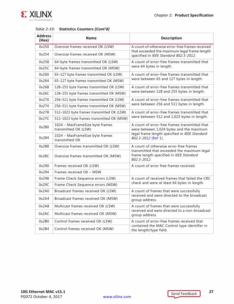
0x250 Oversize frames received OK (LSW) A count of otherwise error-free frames received that exceeded the maximum legal frame length specified in IEEE Standard 802.3-2012.0x254 Oversize frames received OK (MSW)
0x258 64-byte frames transmitted OK (LSW) A count of error-free frames transmitted that were 64 bytes in length.0x25C 64-byte frames transmitted OK (MSW)
0x260 65–127 byte frames transmitted OK (LSW) A count of error-free frames transmitted that were between 65 and 127 bytes in length.0x264 65–127 byte frames transmitted OK (MSW)
0x268 128–255 byte frames transmitted OK (LSW) A count of error-free frames transmitted that were between 128 and 255 bytes in length.0x26C 128–255 byte frames transmitted OK (MSW)
0x270 256–511 byte frames transmitted OK (LSW) A count of error-free frames transmitted that were between 256 and 511 bytes in length.0x274 256–511 byte frames transmitted OK (MSW)
0x278 512–1023 byte frames transmitted OK (LSW) A count of error-free frames transmitted that were between 512 and 1,023 bytes in length.0x27C 512–1023 byte frames transmitted OK (MSW)
0x280 1024 – MaxFrameSize byte frames transmitted OK (LSW)
A count of error-free frames transmitted that were between 1,024 bytes and the maximum legal frame length specified in IEEE Standard 802.3-2012 [Ref 1].0x284 1024 – MaxFrameSize byte frames
transmitted OK
0x288 Oversize frames transmitted OK (LSW) A count of otherwise error-free frames transmitted that exceeded the maximum legal frame length specified in IEEE Standard 802.3-2012.
0x28C Oversize frames transmitted OK (MSW)
0x290 Frames received OK (LSW) A count of error free frames received.
0x294 Frames received OK – MSW
0x298 Frame Check Sequence errors (LSW) A count of received frames that failed the CRC check and were at least 64 bytes in length.0x29C Frame Check Sequence errors (MSW)
0x2A0 Broadcast frames received OK (LSW) A count of frames that were successfully received and were directed to the broadcast group address.0x2A4 Broadcast frames received OK (MSW)
0x2A8 Multicast frames received OK (LSW) A count of frames that were successfully received and were directed to a non-broadcast group address.0x2AC Multicast frames received OK (MSW)
0x2B0 Control frames received OK (LSW) A count of error-free frames received that contained the MAC Control type identifier in the length/type field.0x2B4 Control frames received OK (MSW)
Table 2-19: Statistics Counters (Cont’d)
Address(Hex) Name Description
Send Feedback
10G Ethernet MAC v15.1 28PG072 October 4, 2017 www.xilinx.com
Chapter 2: Product Specification
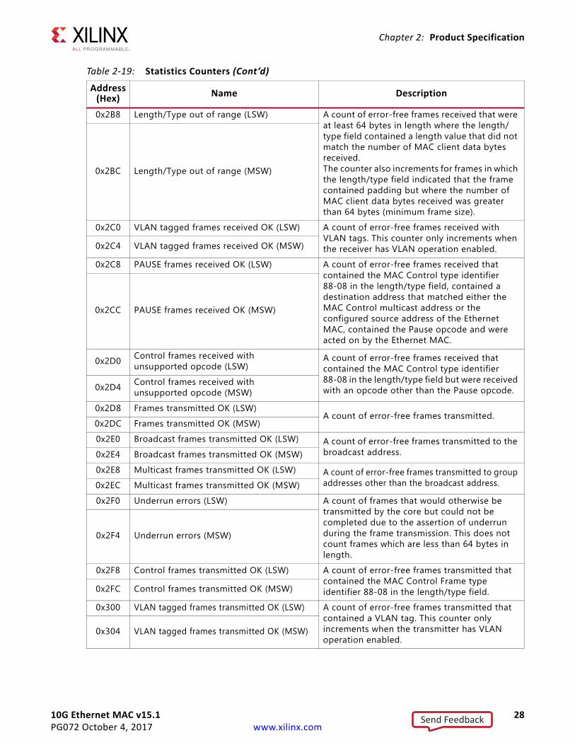
0x2B8 Length/Type out of range (LSW) A count of error-free frames received that were at least 64 bytes in length where the length/type field contained a length value that did not match the number of MAC client data bytes received.The counter also increments for frames in which the length/type field indicated that the frame contained padding but where the number of MAC client data bytes received was greater than 64 bytes (minimum frame size).
0x2BC Length/Type out of range (MSW)
0x2C0 VLAN tagged frames received OK (LSW) A count of error-free frames received with VLAN tags. This counter only increments when the receiver has VLAN operation enabled.0x2C4 VLAN tagged frames received OK (MSW)
0x2C8 PAUSE frames received OK (LSW) A count of error-free frames received that contained the MAC Control type identifier 88-08 in the length/type field, contained a destination address that matched either the MAC Control multicast address or the configured source address of the Ethernet MAC, contained the Pause opcode and were acted on by the Ethernet MAC.
0x2CC PAUSE frames received OK (MSW)
0x2D0 Control frames received with unsupported opcode (LSW)
A count of error-free frames received that contained the MAC Control type identifier 88-08 in the length/type field but were received with an opcode other than the Pause opcode.0x2D4 Control frames received with
unsupported opcode (MSW)
0x2D8 Frames transmitted OK (LSW)A count of error-free frames transmitted.
0x2DC Frames transmitted OK (MSW)
0x2E0 Broadcast frames transmitted OK (LSW) A count of error-free frames transmitted to the broadcast address.0x2E4 Broadcast frames transmitted OK (MSW)
0x2E8 Multicast frames transmitted OK (LSW) A count of error-free frames transmitted to group addresses other than the broadcast address.0x2EC Multicast frames transmitted OK (MSW)
0x2F0 Underrun errors (LSW) A count of frames that would otherwise be transmitted by the core but could not be completed due to the assertion of underrun during the frame transmission. This does not count frames which are less than 64 bytes in length.
0x2F4 Underrun errors (MSW)
0x2F8 Control frames transmitted OK (LSW) A count of error-free frames transmitted that contained the MAC Control Frame type identifier 88-08 in the length/type field.0x2FC Control frames transmitted OK (MSW)
0x300 VLAN tagged frames transmitted OK (LSW) A count of error-free frames transmitted that contained a VLAN tag. This counter only increments when the transmitter has VLAN operation enabled.
0x304 VLAN tagged frames transmitted OK (MSW)
Table 2-19: Statistics Counters (Cont’d)
Address(Hex) Name Description
Send Feedback
10G Ethernet MAC v15.1 29PG072 October 4, 2017 www.xilinx.com
Chapter 2: Product Specification
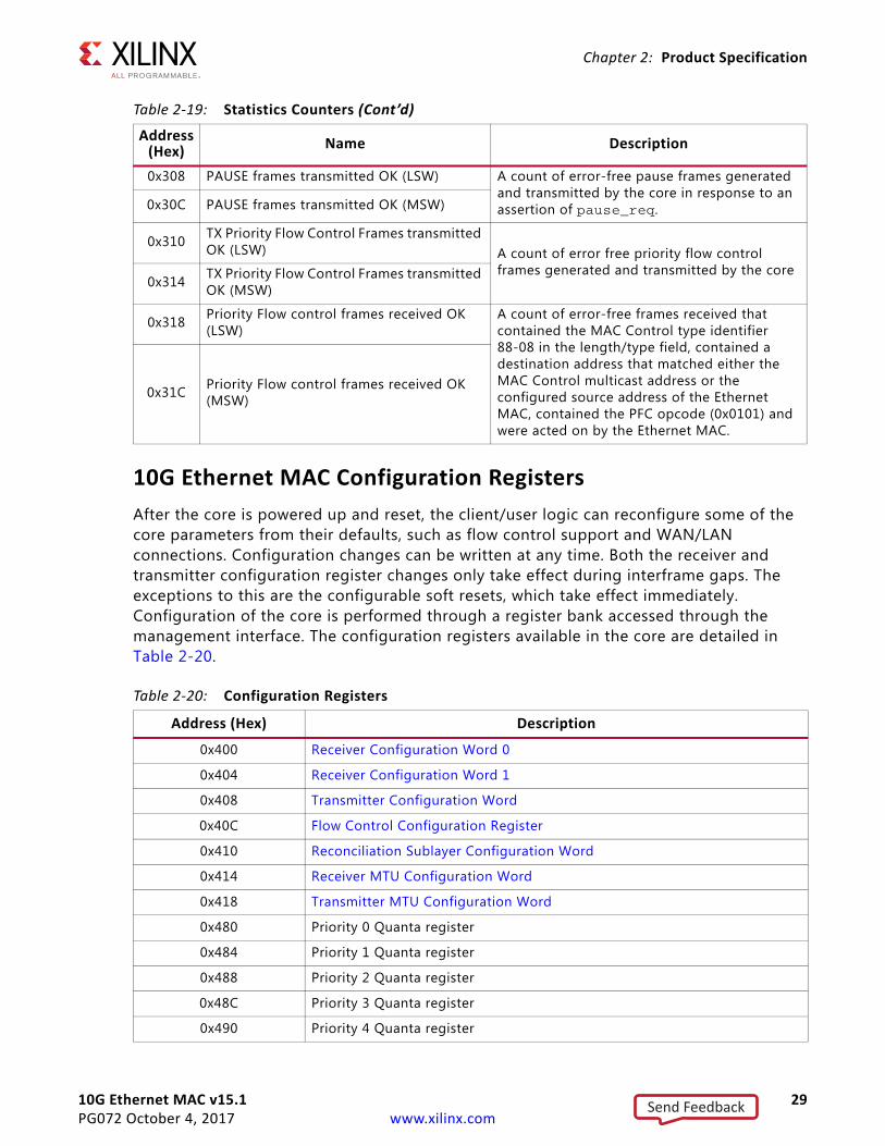
10G Ethernet MAC Configuration RegistersAfter the core is powered up and reset, the client/user logic can reconfigure some of the core parameters from their defaults, such as flow control support and WAN/LAN connections. Configuration changes can be written at any time. Both the receiver and transmitter configuration register changes only take effect during interframe gaps. The exceptions to this are the configurable soft resets, which take effect immediately. Configuration of the core is performed through a register bank accessed through the management interface. The configuration registers available in the core are detailed in Table 2-20.
0x308 PAUSE frames transmitted OK (LSW) A count of error-free pause frames generated and transmitted by the core in response to an assertion of pause_req.0x30C PAUSE frames transmitted OK (MSW)
0x310 TX Priority Flow Control Frames transmitted OK (LSW) A count of error free priority flow control
frames generated and transmitted by the core0x314 TX Priority Flow Control Frames transmitted
OK (MSW)
0x318 Priority Flow control frames received OK (LSW)
A count of error-free frames received that contained the MAC Control type identifier 88-08 in the length/type field, contained a destination address that matched either the MAC Control multicast address or the configured source address of the Ethernet MAC, contained the PFC opcode (0x0101) and were acted on by the Ethernet MAC.
0x31C Priority Flow control frames received OK (MSW)
Table 2-20: Configuration Registers
Address (Hex) Description
0x400 Receiver Configuration Word 0
0x404 Receiver Configuration Word 1
0x408 Transmitter Configuration Word
0x40C Flow Control Configuration Register
0x410 Reconciliation Sublayer Configuration Word
0x414 Receiver MTU Configuration Word
0x418 Transmitter MTU Configuration Word
0x480 Priority 0 Quanta register
0x484 Priority 1 Quanta register
0x488 Priority 2 Quanta register
0x48C Priority 3 Quanta register
0x490 Priority 4 Quanta register
Table 2-19: Statistics Counters (Cont’d)
Address(Hex) Name Description
Send Feedback
10G Ethernet MAC v15.1 30PG072 October 4, 2017 www.xilinx.com
Chapter 2: Product Specification
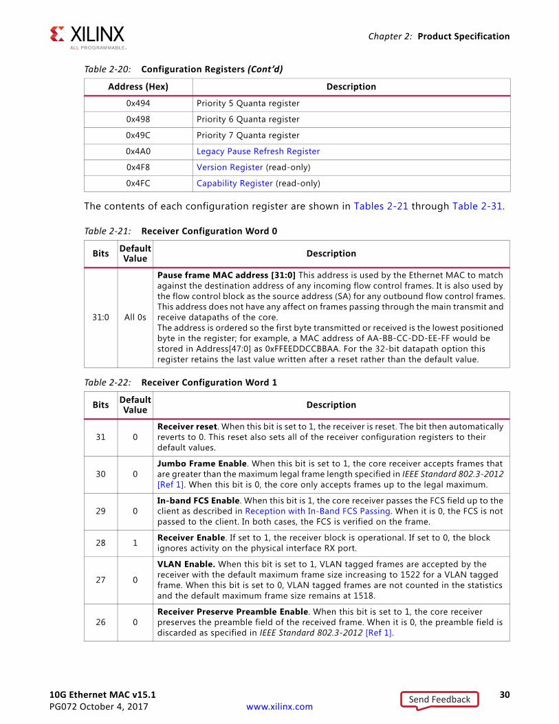
The contents of each configuration register are shown in Tables 2-21 through Table 2-31.
0x494 Priority 5 Quanta register
0x498 Priority 6 Quanta register
0x49C Priority 7 Quanta register
0x4A0 Legacy Pause Refresh Register
0x4F8 Version Register (read-only)
0x4FC Capability Register (read-only)
Table 2-21: Receiver Configuration Word 0
Bits DefaultValue Description
31:0 All 0s
Pause frame MAC address [31:0] This address is used by the Ethernet MAC to match against the destination address of any incoming flow control frames. It is also used by the flow control block as the source address (SA) for any outbound flow control frames.This address does not have any affect on frames passing through the main transmit and receive datapaths of the core.The address is ordered so the first byte transmitted or received is the lowest positioned byte in the register; for example, a MAC address of AA-BB-CC-DD-EE-FF would be stored in Address[47:0] as 0xFFEEDDCCBBAA. For the 32-bit datapath option this register retains the last value written after a reset rather than the default value.
Table 2-22: Receiver Configuration Word 1
Bits DefaultValue Description
31 0Receiver reset. When this bit is set to 1, the receiver is reset. The bit then automatically reverts to 0. This reset also sets all of the receiver configuration registers to their default values.
30 0Jumbo Frame Enable. When this bit is set to 1, the core receiver accepts frames that are greater than the maximum legal frame length specified in IEEE Standard 802.3-2012 [Ref 1]. When this bit is 0, the core only accepts frames up to the legal maximum.
29 0In-band FCS Enable. When this bit is 1, the core receiver passes the FCS field up to the client as described in Reception with In-Band FCS Passing. When it is 0, the FCS is not passed to the client. In both cases, the FCS is verified on the frame.
28 1 Receiver Enable. If set to 1, the receiver block is operational. If set to 0, the block ignores activity on the physical interface RX port.
27 0
VLAN Enable. When this bit is set to 1, VLAN tagged frames are accepted by the receiver with the default maximum frame size increasing to 1522 for a VLAN tagged frame. When this bit is set to 0, VLAN tagged frames are not counted in the statistics and the default maximum frame size remains at 1518.
26 0Receiver Preserve Preamble Enable. When this bit is set to 1, the core receiver preserves the preamble field of the received frame. When it is 0, the preamble field is discarded as specified in IEEE Standard 802.3-2012 [Ref 1].
Table 2-20: Configuration Registers (Cont’d)
Address (Hex) Description
Send Feedback
10G Ethernet MAC v15.1 31PG072 October 4, 2017 www.xilinx.com
Chapter 2: Product Specification
25 0
Length/Type Error Check Disable. When this bit is set to 1, the core does not perform the length/type field error checks as described in Length/Type Field Error Checks.When this bit is set to 0, the length/type field checks are performed; this is normal operation.
24 0 Control Frame Length Check Disable. When this bit is set to 1, the core does not mark MAC Control frames as “bad” if they are greater than minimum frame length.
23 0
Enhanced VLAN Mode Enable. When enabled, the MAC performs the length/type field error check (as described in Length/Type Field Error Checks) and also performs any padding removal, if applicable, using the length/type field following the VLAN tag. It can also perform this check following stacked VLAN tags if Stacked VLAN mode enable is set.
22 Reserved
21 0Stacked VLAN Mode Enable. When this bit is set to 1, the core supports stacked VLAN frames (frames with up to 8 cascaded VLAN tags). This mode also enables identification of VLAN tags using the TAG field value of 0x88A8 (in addition to 0x8100).
20:16 N/A Reserved
15:0 All 0s Pause frame MAC address [47:32]. See description in Table 2-21.
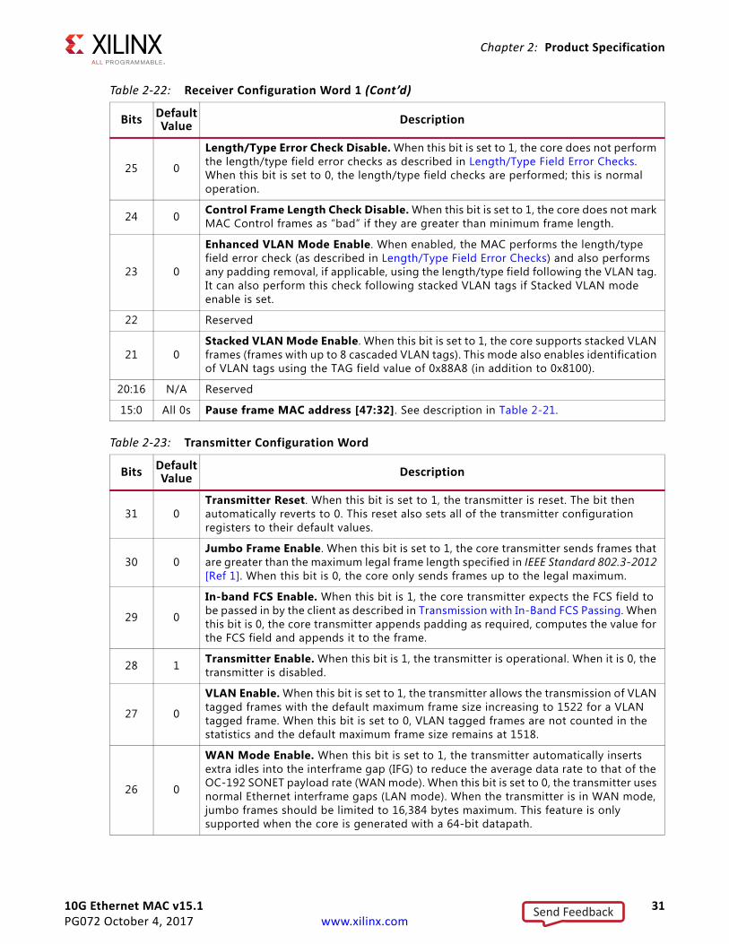
Table 2-23: Transmitter Configuration Word
Bits Default Value Description
31 0Transmitter Reset. When this bit is set to 1, the transmitter is reset. The bit then automatically reverts to 0. This reset also sets all of the transmitter configuration registers to their default values.
30 0Jumbo Frame Enable. When this bit is set to 1, the core transmitter sends frames that are greater than the maximum legal frame length specified in IEEE Standard 802.3-2012 [Ref 1]. When this bit is 0, the core only sends frames up to the legal maximum.
29 0
In-band FCS Enable. When this bit is 1, the core transmitter expects the FCS field to be passed in by the client as described in Transmission with In-Band FCS Passing. When this bit is 0, the core transmitter appends padding as required, computes the value for the FCS field and appends it to the frame.
28 1 Transmitter Enable. When this bit is 1, the transmitter is operational. When it is 0, the transmitter is disabled.
27 0
VLAN Enable. When this bit is set to 1, the transmitter allows the transmission of VLAN tagged frames with the default maximum frame size increasing to 1522 for a VLAN tagged frame. When this bit is set to 0, VLAN tagged frames are not counted in the statistics and the default maximum frame size remains at 1518.
26 0
WAN Mode Enable. When this bit is set to 1, the transmitter automatically inserts extra idles into the interframe gap (IFG) to reduce the average data rate to that of the OC-192 SONET payload rate (WAN mode). When this bit is set to 0, the transmitter uses normal Ethernet interframe gaps (LAN mode). When the transmitter is in WAN mode, jumbo frames should be limited to 16,384 bytes maximum. This feature is only supported when the core is generated with a 64-bit datapath.
Table 2-22: Receiver Configuration Word 1 (Cont’d)
Bits DefaultValue Description
Send Feedback
10G Ethernet MAC v15.1 32PG072 October 4, 2017 www.xilinx.com
Chapter 2: Product Specification
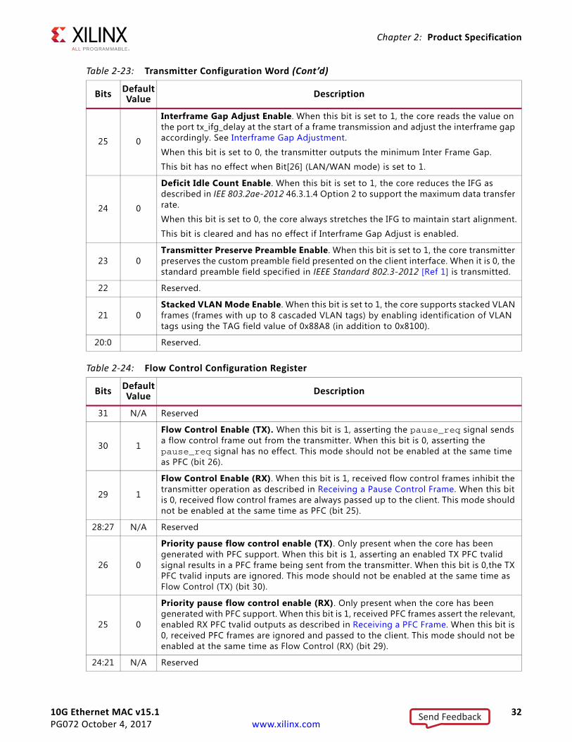
25 0
Interframe Gap Adjust Enable. When this bit is set to 1, the core reads the value on the port tx_ifg_delay at the start of a frame transmission and adjust the interframe gap accordingly. See Interframe Gap Adjustment.
When this bit is set to 0, the transmitter outputs the minimum Inter Frame Gap.
This bit has no effect when Bit[26] (LAN/WAN mode) is set to 1.
24 0
Deficit Idle Count Enable. When this bit is set to 1, the core reduces the IFG as described in IEE 803.2ae-2012 46.3.1.4 Option 2 to support the maximum data transfer rate.
When this bit is set to 0, the core always stretches the IFG to maintain start alignment.
This bit is cleared and has no effect if Interframe Gap Adjust is enabled.
23 0Transmitter Preserve Preamble Enable. When this bit is set to 1, the core transmitter preserves the custom preamble field presented on the client interface. When it is 0, the standard preamble field specified in IEEE Standard 802.3-2012 [Ref 1] is transmitted.
22 Reserved.
21 0Stacked VLAN Mode Enable. When this bit is set to 1, the core supports stacked VLAN frames (frames with up to 8 cascaded VLAN tags) by enabling identification of VLAN tags using the TAG field value of 0x88A8 (in addition to 0x8100).
20:0 Reserved.
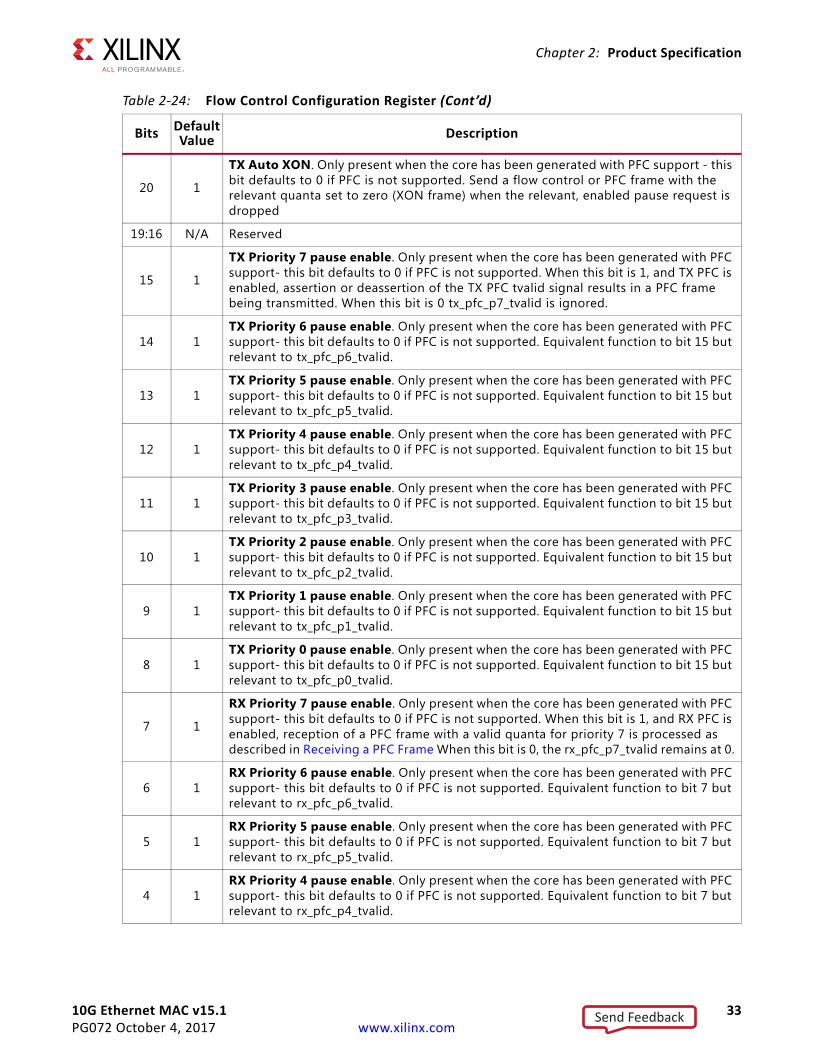
Table 2-24: Flow Control Configuration Register
Bits DefaultValue Description
31 N/A Reserved
30 1
Flow Control Enable (TX). When this bit is 1, asserting the pause_req signal sends a flow control frame out from the transmitter. When this bit is 0, asserting the pause_req signal has no effect. This mode should not be enabled at the same time as PFC (bit 26).
29 1
Flow Control Enable (RX). When this bit is 1, received flow control frames inhibit the transmitter operation as described in Receiving a Pause Control Frame. When this bit is 0, received flow control frames are always passed up to the client. This mode should not be enabled at the same time as PFC (bit 25).
28:27 N/A Reserved
26 0
Priority pause flow control enable (TX). Only present when the core has been generated with PFC support. When this bit is 1, asserting an enabled TX PFC tvalid signal results in a PFC frame being sent from the transmitter. When this bit is 0,the TX PFC tvalid inputs are ignored. This mode should not be enabled at the same time as Flow Control (TX) (bit 30).
25 0
Priority pause flow control enable (RX). Only present when the core has been generated with PFC support. When this bit is 1, received PFC frames assert the relevant, enabled RX PFC tvalid outputs as described in Receiving a PFC Frame. When this bit is 0, received PFC frames are ignored and passed to the client. This mode should not be enabled at the same time as Flow Control (RX) (bit 29).
24:21 N/A Reserved
Table 2-23: Transmitter Configuration Word (Cont’d)
Bits Default Value Description
Send Feedback
10G Ethernet MAC v15.1 33PG072 October 4, 2017 www.xilinx.com
Chapter 2: Product Specification
20 1
TX Auto XON. Only present when the core has been generated with PFC support - this bit defaults to 0 if PFC is not supported. Send a flow control or PFC frame with the relevant quanta set to zero (XON frame) when the relevant, enabled pause request is dropped
19:16 N/A Reserved
15 1
TX Priority 7 pause enable. Only present when the core has been generated with PFC support- this bit defaults to 0 if PFC is not supported. When this bit is 1, and TX PFC is enabled, assertion or deassertion of the TX PFC tvalid signal results in a PFC frame being transmitted. When this bit is 0 tx_pfc_p7_tvalid is ignored.
14 1TX Priority 6 pause enable. Only present when the core has been generated with PFC support- this bit defaults to 0 if PFC is not supported. Equivalent function to bit 15 but relevant to tx_pfc_p6_tvalid.
13 1TX Priority 5 pause enable. Only present when the core has been generated with PFC support- this bit defaults to 0 if PFC is not supported. Equivalent function to bit 15 but relevant to tx_pfc_p5_tvalid.
12 1TX Priority 4 pause enable. Only present when the core has been generated with PFC support- this bit defaults to 0 if PFC is not supported. Equivalent function to bit 15 but relevant to tx_pfc_p4_tvalid.
11 1TX Priority 3 pause enable. Only present when the core has been generated with PFC support- this bit defaults to 0 if PFC is not supported. Equivalent function to bit 15 but relevant to tx_pfc_p3_tvalid.
10 1TX Priority 2 pause enable. Only present when the core has been generated with PFC support- this bit defaults to 0 if PFC is not supported. Equivalent function to bit 15 but relevant to tx_pfc_p2_tvalid.
9 1TX Priority 1 pause enable. Only present when the core has been generated with PFC support- this bit defaults to 0 if PFC is not supported. Equivalent function to bit 15 but relevant to tx_pfc_p1_tvalid.
8 1TX Priority 0 pause enable. Only present when the core has been generated with PFC support- this bit defaults to 0 if PFC is not supported. Equivalent function to bit 15 but relevant to tx_pfc_p0_tvalid.
7 1
RX Priority 7 pause enable. Only present when the core has been generated with PFC support- this bit defaults to 0 if PFC is not supported. When this bit is 1, and RX PFC is enabled, reception of a PFC frame with a valid quanta for priority 7 is processed as described in Receiving a PFC Frame When this bit is 0, the rx_pfc_p7_tvalid remains at 0.
6 1RX Priority 6 pause enable. Only present when the core has been generated with PFC support- this bit defaults to 0 if PFC is not supported. Equivalent function to bit 7 but relevant to rx_pfc_p6_tvalid.
5 1RX Priority 5 pause enable. Only present when the core has been generated with PFC support- this bit defaults to 0 if PFC is not supported. Equivalent function to bit 7 but relevant to rx_pfc_p5_tvalid.
4 1RX Priority 4 pause enable. Only present when the core has been generated with PFC support- this bit defaults to 0 if PFC is not supported. Equivalent function to bit 7 but relevant to rx_pfc_p4_tvalid.
Table 2-24: Flow Control Configuration Register (Cont’d)
Bits DefaultValue Description
Send Feedback
10G Ethernet MAC v15.1 34PG072 October 4, 2017 www.xilinx.com
Chapter 2: Product Specification
3 1RX Priority 3 pause enable. Only present when the core has been generated with PFC support- this bit defaults to 0 if PFC is not supported. Equivalent function to bit 7 but relevant to rx_pfc_p3_tvalid.
2 1RX Priority 2 pause enable. Only present when the core has been generated with PFC support- this bit defaults to 0 if PFC is not supported. Equivalent function to bit 7 but relevant to rx_pfc_p2_tvalid.
1 1RX Priority 1 pause enable. Only present when the core has been generated with PFC support- this bit defaults to 0 if PFC is not supported. Equivalent function to bit 7 but relevant to rx_pfc_p1_tvalid.
0 1RX Priority 0 pause enable. Only present when the core has been generated with PFC support- this bit defaults to 0 if PFC is not supported. Equivalent function to bit 7 but relevant to rx_pfc_p0_tvalid.
Table 2-25: Reconciliation Sublayer Configuration Word
Bits DefaultValue Description
31 N/AReceive DCM Locked. If this bit is 1, the Digital Clock Management (DCM) block for the receive-side clocks (XGMII_RX_CLK, RX_CLK) is locked. If this bit is 0, the DCM is not locked. Read-only.
30 N/ATransmit DCM Locked. If this bit is 1, the DCM block for the transmit-side clocks (GTX_CLK, XGMII_TX_CLK, TX_CLK) is locked. If this bit is 0, the DCM is not locked. Read-only.
29 N/A Remote Fault Received. If this bit is 1, the RS layer is receiving remote fault sequence ordered sets. Read-only.
28 N/A Local Fault Received. If this bit is 1, the RS layer is receiving local fault sequence ordered sets. Read-only.
27 0
Fault Inhibit. When this bit is set to 0, the Reconciliation Sublayer transmits ordered sets as laid out in IEEE Standard 802.3-2012 [Ref 1]; that is, when the RS is receiving Local Fault or Link Interruption ordered sets, it transmits Remote Fault ordered sets. When it is receiving Remote Fault ordered sets, it transmits idles code words.When this bit is set to 1, the reconciliation sublayer always transmits data presented to it by the core, regardless of whether fault ordered sets are being received.
26 0 Link Interruption Detected If this bit is 1, then the RS layer is receiving link interruption sequence ordered sets. Read-only.
25:0 N/A Reserved
Table 2-26: Receiver MTU Configuration Word
Bits DefaultValue Description
31:17 N/A Reserved
16 0RX MTU Enable. When this bit is set to 1, the value in RX MTU Size is used as the maximum frame size allowed as described in Receiver Maximum Permitted Frame Length. When set to 0 frame handling depends on the other configuration settings.
Table 2-24: Flow Control Configuration Register (Cont’d)
Bits DefaultValue Description
Send Feedback
10G Ethernet MAC v15.1 35PG072 October 4, 2017 www.xilinx.com
Chapter 2: Product Specification
15 N/A Reserved
14:0 0x05EE
RX MTU Size. This value is used as the maximum frame size allowed as described in Receiver Maximum Permitted Frame Length when RX MTU Enable is set to 1. Only values of 1,518 or greater are legal for RX MTU size and the core does not enforce this size on write. Ensure that only legal values are written to this register for correct core operation.
Table 2-27: Transmitter MTU Configuration Word
Bits DefaultValue Description
31:17 N/A Reserved
16 0TX MTU Enable. When this bit is set to 1, the value in TX MTU Size is used as the maximum frame size allowed as described in Transmitter Maximum Permitted Frame Length. When set to 0 frame handling depends on the other configuration settings.
15 N/A Reserved
14:0 0x05EE
TX MTU Size. This value is used as the maximum frame size allowed as described in Transmitter Maximum Permitted Frame Length when TX MTU Enable is set to 1. Only values of 1,518 or greater are legal for TX MTU size and the core does not enforce this size on write. Ensure that only legal values are written to this register for correct core operation.
Table 2-28: Per Priority Quanta/Refresh Register (0x480/0x49C)
Bits Default Description
31:16 0xff00
Pause Quanta refresh value. This register is only present when PFC is enabled at the core customization time. When enabled, this register controls how frequently a PFC quanta is refreshed by the transmission of a new PFC frame. When a refresh occurs, all currently active (TX PFC tvalid is High and enabled) priorities are refreshed.
15:0 0xFFFFPause Quanta value. This register is only present when PFC is enabled at core customization time. When enabled, this register sets the quanta value to be inserted in the PFC frame for this priority.
Notes: 1. This register is repeated for the eight priorities, priority 0 to priority 7.2. These registers only exist when the core is generated with PFC support.3. These registers are not affected by a reset and retain the last value written to them.
Table 2-26: Receiver MTU Configuration Word (Cont’d)
Bits DefaultValue Description
Send Feedback
10G Ethernet MAC v15.1 36PG072 October 4, 2017 www.xilinx.com
Chapter 2: Product Specification
Table 2-29: Legacy Pause Refresh Register
Bits Default Description
31:16 0xff00
Pause Quanta refresh value. This register is only present when PFC is enabled at the core customization time. When PFC is supported, the 802.3 pause request can also support XON/XOFF Extended Functionality. This controls the frequency of the automatic pause refresh.
15:0 0x0 Reserved
Notes: 1. These registers only exist when the core is generated with PFC support.2. These registers are not affected by a reset and retain the last value written to them.
Table 2-30: Version Register
Bits DefaultValue Description
31:24 0x0F Major Revision. This field indicates the major revision of the core.
23:16 0x01 Minor Revision. This field indicates the minor revision of the core.
15:8 N/A Reserved
7:0 All 0s Patch Level. This field indicates the patch status of the core. (When this value is 0x00 it indicates a non-patched version, when 0x01 indicates Rev 1, etc.)
Table 2-31: Capability Register
Bits DefaultValue Description
31:9 N/A Reserved
16 0 PFC Support. This bit indicates that the core has been generated with PFC support.
15:9 N/A Reserved.
8 1 Statistics Counter. This bit indicates that the core has statistics counters.
7:6 N/A Reserved.
5 1 Line rate 10 Gbit. This bit indicates that the core supports the 10 Gb line rate.
4 N/A Reserved.
3 0 Line rate 2.5 Gbit. This bit indicates that the core supports the 2.5 Gb line rate.
2 0 Line rate 1 Gbit. This bit indicates that the core supports the 1 Gb line rate.
1 0 Line rate 100 Mbit. This bit indicates that the core supports the 100 Mb line rate.
0 0 Line rate 10 Mbit. This bit indicates that the core has a capability to support the 10 Mb line rate.
Send Feedback
10G Ethernet MAC v15.1 37PG072 October 4, 2017 www.xilinx.com
Chapter 2: Product Specification
MDIO Control RegistersA list of MDIO registers is shown in Table 2-32.
The contents of each configuration register are shown in Table 2-33 through Table 2-36.
Table 2-32: MDIO Configuration Registers
Address (Hex) Description
0x500 MDIO Configuration Word 0
0x504 MDIO Configuration Word 1
0x508 MDIO TX Data
0x50C MDIO RX Data (read-only)
Table 2-33: MDIO Configuration Word 0
Bits Default Value Description
31:7 N/A Reserved
6 0MDIO Enable. When this bit is 1, the MDIO interface can be used to access attached PHY devices. When this bit is 0, the MDIO interface is disabled and the MDIO signal remains inactive.
5:0 All 0s Clock Divide. Used as a divider value to generate the MDC signal at 2.5 MHz. See MDIO Interface.
Table 2-34: MDIO Configuration Word 1
Bits DefaultValue Description
31:29 N/A Reserved
28:24 All 0s PRTAD. Port address for the MDIO transaction
23:21 N/A Reserved
20:16 All 0s DEVAD. Device address for the MDIO transaction
15:14 0 TX OP. Opcode for the MDIO transaction.
13:12 N/A Reserved
10:8 N/A Reserved
11 0 Initiate. If a 1 is written to this bit when MDIO Ready is 1, an MDIO transaction is initiated. This bit goes to 0 automatically when the pending transaction completed.
7 1MDIO Ready. When this bit is 1, the MDIO master is ready for an MDIO transaction. When this bit is 0, MDIO master is busy in a transaction and goes to 1 when the pending transaction is complete. This bit is read-only.
6:0 N/A Reserved
Send Feedback

10G Ethernet MAC v15.1 38PG072 October 4, 2017 www.xilinx.com
Chapter 2: Product Specification
Interrupt Output RegistersThe core can assert an interrupt when a pending MDIO transaction is completed. If enabled through the Interrupt Enable Register, on the rising edge of xgmacint, the MDIO transaction is complete. Furthermore, if the transaction was an MDIO read, the MDIO RX data results are in the management register 0x50C. An Interrupt Acknowledge must be issued to clear the interrupt before a new MDIO transaction can be started because the interrupt does not self clear. Table 2-37 lists the Interrupt registers.
Bit[0] of all the interrupt registers is used to indicate that the MDIO transaction has completed. Bits[31:1] are reserved.
Table 2-35: MDIO TX Data
Bits Default Value Description
31:16 N/A Reserved
15:0 All 0s MDIO TX Data. MDIO Write data. Can be the address of the device based on the opcode.
Table 2-36: MDIO RX Data
Bits Default Value Description
31:17 N/A Reserved
16 1MDIO Ready. When this bit is 1, the MDIO master is ready for an MDIO transaction. When this bit is 0, MDIO master is busy in a transaction and goes to 1 when the pending transaction is complete. This bit is read-only.
15:0 All 0s MDIO RX Data. MDIO Read data.
Table 2-37: Interrupt Registers
Address(Hex)
DefaultValue Description
0x600 0x00 Interrupt Status Register. Indicates the status of an interrupt. Any asserted interrupt can be cleared by directly writing a 0 to the concerned bit location.
0x610 0x00Interrupt Pending Register. Indicates the pending status of an interrupt. Writing a 1 to any bit of this register clears that particular interrupt. Bits in this register are set only when the corresponding bits in IER and ISR are set.
0x620 0x00 Interrupt Enable Register. Indicates the enable state of an interrupt. Writing a 1 to any bit enables that particular interrupt.
0x630 0x00 Interrupt Acknowledge Register. (Write only) Writing a 1 to any bit of this register clears that particular interrupt.
Send Feedback
10G Ethernet MAC v15.1 39PG072 October 4, 2017 www.xilinx.com
Chapter 3
Designing with the CoreThis chapter includes guidelines and additional information to facilitate designing with the core.
General Design GuidelinesThis section describes the steps required to turn a 10G Ethernet MAC core into a fully functioning design with user application logic. Not all implementations require all of the design steps listed in this section. Follow the logic design guidelines in this document carefully.
Use the Example Design as a Starting PointEvery instance of the core created by the Vivado® IP catalog is delivered with an example design that can be implemented in an FPGA and simulated. This design can be used as a starting point for your own design or can be used to sanity-check your application in the event of difficulty.
For information on using and customizing the example designs for the core, see Chapter 5, Example Design.
Know the Degree of DifficultyEthernet designs are challenging to implement in any technology. The degree of difficulty is influenced by:
• Maximum system clock frequency
• Targeted device architecture
• Nature of the user application
All 10 Gb/s Ethernet implementations need careful attention to system performance requirements. Pipelining, logic mapping, placement constraints, and logic duplication are all methods that help boost system performance.
Send Feedback
10G Ethernet MAC v15.1 40PG072 October 4, 2017 www.xilinx.com
Chapter 3: Designing with the Core
Keep It RegisteredTo simplify timing and increase system performance in an FPGA design, keep all inputs and outputs registered between the user application and the core. This means that all inputs and outputs from the user application should come from, or connect to, a flip-flop. While registering signals might not be possible for all paths, it simplifies timing analysis and makes it easier for the Xilinx tools to place and route the design.
Recognize Timing Critical SignalsThe XDC constraints file provided with the example design for the core identifies the critical signals and the timing constraints that should be applied. For further information, see Constraining the Core.
Make Only Allowed ModificationsDo not make modifications as they can have adverse effects on system timing and protocol compliance. Supported user configurations of the core can only be made by the selecting the options from within the Vivado IP catalog when the core is generated. For more information, see Chapter 4, Design Flow Steps.
Shared LogicThe core supported up to version 12.0 and the RTL core hierarchy was fixed. This resulted in some difficulty because shareable clocking and reset logic needed to be extracted from the core example design for use with a single instance, or multiple instances of the core.
Shared Logic is a new feature that provides a more flexible architecture that works both as a standalone core and as a part of a larger design with one or more core instances. This minimizes the amount of HDL modifications required, but at the same time retains the flexibility to address more uses of the core.
The new level of hierarchy is called <component_name>_support. Figure 3-1 and Figure 3-2 show two hierarchies where the shared logic block is contained either in the core or in the example design. In these figures, <component_name> is the name of the generated core. The difference between the two hierarchies is the boundary of the core. It is controlled using the Shared Logic option in the Vivado Integrated Design Environment (IDE) (see Figure 4-2 in Chapter 4, Design Flow Steps).
Send Feedback
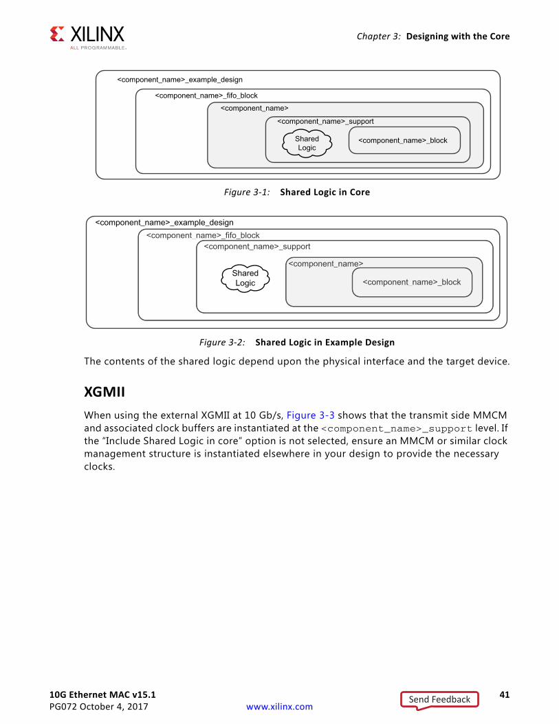
10G Ethernet MAC v15.1 41PG072 October 4, 2017 www.xilinx.com
Chapter 3: Designing with the Core
The contents of the shared logic depend upon the physical interface and the target device.
XGMIIWhen using the external XGMII at 10 Gb/s, Figure 3-3 shows that the transmit side MMCM and associated clock buffers are instantiated at the <component_name>_support level. If the “Include Shared Logic in core” option is not selected, ensure an MMCM or similar clock management structure is instantiated elsewhere in your design to provide the necessary clocks.
X-Ref Target - Figure 3-1
Figure 3-1: Shared Logic in CoreX-Ref Target - Figure 3-2
Figure 3-2: Shared Logic in Example Design
Send Feedback
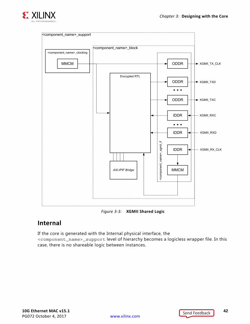
10G Ethernet MAC v15.1 42PG072 October 4, 2017 www.xilinx.com
Chapter 3: Designing with the Core
InternalIf the core is generated with the Internal physical interface, the <component_name>_support level of hierarchy becomes a logicless wrapper file. In this case, there is no shareable logic between instances.
X-Ref Target - Figure 3-3
Figure 3-3: XGMII Shared Logic
Send Feedback
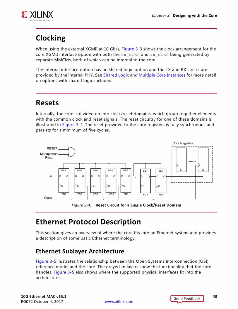
10G Ethernet MAC v15.1 43PG072 October 4, 2017 www.xilinx.com
Chapter 3: Designing with the Core
ClockingWhen using the external XGMII at 10 Gb/s, Figure 3-3 shows the clock arrangement for the core XGMII interface option with both the tx_clk0 and rx_clk0 being generated by separate MMCMs, both of which can be internal to the core.
The internal interface option has no shared logic option and the TX and RX clocks are provided by the internal PHY. See Shared Logic and Multiple Core Instances for more detail on options with shared logic included.
ResetsInternally, the core is divided up into clock/reset domains, which group together elements with the common clock and reset signals. The reset circuitry for one of these domains is illustrated in Figure 3-4. The reset provided to the core registers is fully synchronous and persists for a minimum of five cycles.
X-Ref Target - Figure 3-4
Ethernet Protocol DescriptionThis section gives an overview of where the core fits into an Ethernet system and provides a description of some basic Ethernet terminology.
Ethernet Sublayer ArchitectureFigure 3-5illustrates the relationship between the Open Systems Interconnection (OSI) reference model and the core. The grayed-in layers show the functionality that the core handles. Figure 3-5 also shows where the supported physical interfaces fit into the architecture.
Figure 3-4: Reset Circuit for a Single Clock/Reset Domain
Send Feedback
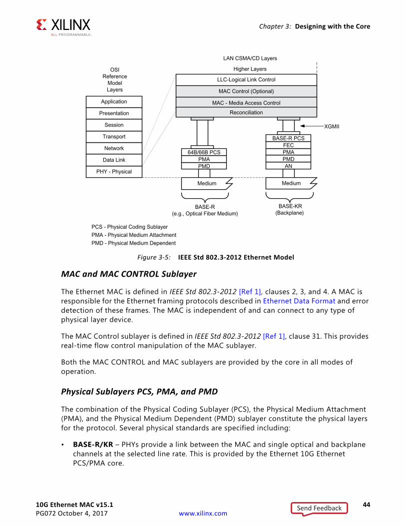
10G Ethernet MAC v15.1 44PG072 October 4, 2017 www.xilinx.com
Chapter 3: Designing with the Core
MAC and MAC CONTROL Sublayer
The Ethernet MAC is defined in IEEE Std 802.3-2012 [Ref 1], clauses 2, 3, and 4. A MAC is responsible for the Ethernet framing protocols described in Ethernet Data Format and error detection of these frames. The MAC is independent of and can connect to any type of physical layer device.
The MAC Control sublayer is defined in IEEE Std 802.3-2012 [Ref 1], clause 31. This provides real-time flow control manipulation of the MAC sublayer.
Both the MAC CONTROL and MAC sublayers are provided by the core in all modes of operation.
Physical Sublayers PCS, PMA, and PMD
The combination of the Physical Coding Sublayer (PCS), the Physical Medium Attachment (PMA), and the Physical Medium Dependent (PMD) sublayer constitute the physical layers for the protocol. Several physical standards are specified including:
• BASE-R/KR – PHYs provide a link between the MAC and single optical and backplane channels at the selected line rate. This is provided by the Ethernet 10G Ethernet PCS/PMA core.
X-Ref Target - Figure 3-5
Figure 3-5: IEEE Std 802.3-2012 Ethernet Model
Send Feedback
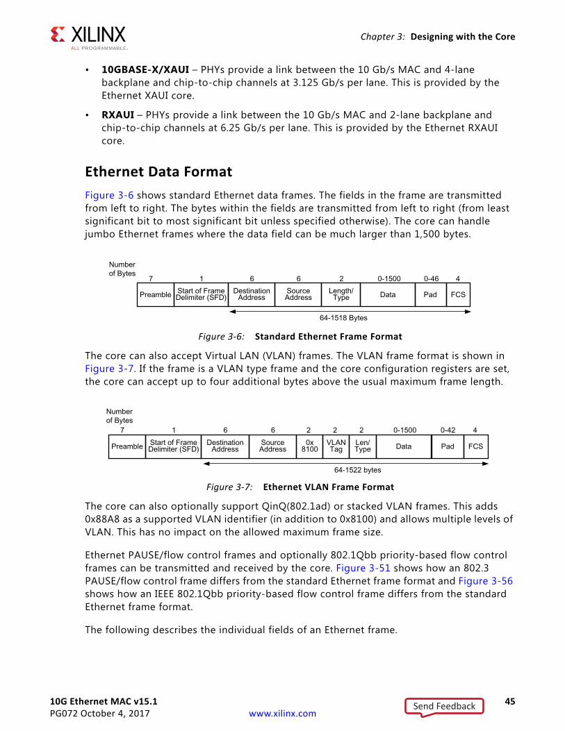
10G Ethernet MAC v15.1 45PG072 October 4, 2017 www.xilinx.com
Chapter 3: Designing with the Core
• 10GBASE-X/XAUI – PHYs provide a link between the 10 Gb/s MAC and 4-lane backplane and chip-to-chip channels at 3.125 Gb/s per lane. This is provided by the Ethernet XAUI core.
• RXAUI – PHYs provide a link between the 10 Gb/s MAC and 2-lane backplane and chip-to-chip channels at 6.25 Gb/s per lane. This is provided by the Ethernet RXAUI core.
Ethernet Data FormatFigure 3-6 shows standard Ethernet data frames. The fields in the frame are transmitted from left to right. The bytes within the fields are transmitted from left to right (from least significant bit to most significant bit unless specified otherwise). The core can handle jumbo Ethernet frames where the data field can be much larger than 1,500 bytes.
The core can also accept Virtual LAN (VLAN) frames. The VLAN frame format is shown in Figure 3-7. If the frame is a VLAN type frame and the core configuration registers are set, the core can accept up to four additional bytes above the usual maximum frame length.
.
The core can also optionally support QinQ(802.1ad) or stacked VLAN frames. This adds 0x88A8 as a supported VLAN identifier (in addition to 0x8100) and allows multiple levels of VLAN. This has no impact on the allowed maximum frame size.
Ethernet PAUSE/flow control frames and optionally 802.1Qbb priority-based flow control frames can be transmitted and received by the core. Figure 3-51 shows how an 802.3 PAUSE/flow control frame differs from the standard Ethernet frame format and Figure 3-56 shows how an IEEE 802.1Qbb priority-based flow control frame differs from the standard Ethernet frame format.
The following describes the individual fields of an Ethernet frame.
X-Ref Target - Figure 3-6
Figure 3-6: Standard Ethernet Frame Format
X-Ref Target - Figure 3-7
Figure 3-7: Ethernet VLAN Frame Format
Send Feedback
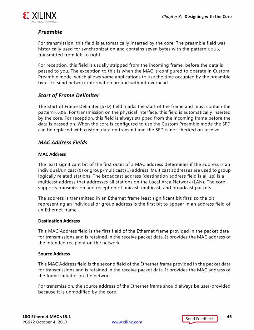
10G Ethernet MAC v15.1 46PG072 October 4, 2017 www.xilinx.com
Chapter 3: Designing with the Core
Preamble
For transmission, this field is automatically inserted by the core. The preamble field was historically used for synchronization and contains seven bytes with the pattern 0x55, transmitted from left to right.
For reception, this field is usually stripped from the incoming frame, before the data is passed to you. The exception to this is when the MAC is configured to operate in Custom Preamble mode, which allows some applications to use the time occupied by the preamble bytes to send network information around without overhead.
Start of Frame Delimiter
The Start of Frame Delimiter (SFD) field marks the start of the frame and must contain the pattern 0xD5. For transmission on the physical interface, this field is automatically inserted by the core. For reception, this field is always stripped from the incoming frame before the data is passed on. When the core is configured to use the Custom Preamble mode the SFD can be replaced with custom data on transmit and the SFD is not checked on receive.
MAC Address Fields
MAC Address
The least significant bit of the first octet of a MAC address determines if the address is an individual/unicast (0) or group/multicast (1) address. Multicast addresses are used to group logically related stations. The broadcast address (destination address field is all 1s) is a multicast address that addresses all stations on the Local Area Network (LAN). The core supports transmission and reception of unicast, multicast, and broadcast packets.
The address is transmitted in an Ethernet frame least significant bit first: so the bit representing an individual or group address is the first bit to appear in an address field of an Ethernet frame.
Destination Address
This MAC Address field is the first field of the Ethernet frame provided in the packet data for transmissions and is retained in the receive packet data. It provides the MAC address of the intended recipient on the network.
Source Address
This MAC Address field is the second field of the Ethernet frame provided in the packet data for transmissions and is retained in the receive packet data. It provides the MAC address of the frame initiator on the network.
For transmission, the source address of the Ethernet frame should always be user-provided because it is unmodified by the core.
Send Feedback
10G Ethernet MAC v15.1 47PG072 October 4, 2017 www.xilinx.com
Chapter 3: Designing with the Core
Length/Type
The value of this field determines if it is interpreted as a length or a type field, as defined by IEEE Std 802.3-2012 [Ref 1]. A value of 1,536 decimal or greater is interpreted by the core as a type field.
When used as a length field, the value in this field represents the number of bytes in the following data field. This value does not include any bytes that can be inserted in the pad field following the data field.
A length/type field value of 0x8100 indicates that the frame is a VLAN frame, and a value of 0x8808 indicates a PAUSE MAC control frame. The core also supports QinQ or stacked VLAN frames, if enabled a length/type value of 0x88A8 is also used to identify a VLAN frame.
For transmission, the core does not perform any processing of the length/type field.
For reception, if this field is a length field, the core receive engine interprets this value and removes any padding in the pad field (if necessary). If the field is a length field and length/type checking is enabled, the core compares the length against the actual data field length and flags an error if a mismatch occurs. If the field is a type field, the core ignores the value and passes it along with the packet data with no further processing. The length/type field is always retained in the receive packet data. The core can optionally perform this length/type check and padding stripping using the length/type field following the final VLAN tag within the frame.
Data
The data field can vary from 0 to 1,500 bytes in length for a normal frame. The core can handle jumbo frames of any length.
This field is always provided in the packet data for transmissions and is always retained in the receive packet data.
Pad
The pad field can vary from 0 to 46 bytes in length. This field is used to ensure that the frame length is at least 64 bytes in length (the preamble and SFD fields are not considered part of the frame for this calculation), which is required for successful CSMA/CD operation. The values in this field are used in the frame check sequence calculation but are not included in the length field value, if it is used. The length of this field and the data field combined must be at least 46 bytes. If the data field contains 0 bytes, the pad field is 46 bytes. If the data field is 46 bytes or more, the pad field has 0 bytes.
For transmission, this field can be inserted automatically by the core or can be supplied by you. If the pad field is inserted by the core, the FCS field is calculated and inserted by the core. If the pad field is supplied by you, the FCS can be either inserted by the core or provided by you, as indicated by a configuration register bit.
Send Feedback
10G Ethernet MAC v15.1 48PG072 October 4, 2017 www.xilinx.com
Chapter 3: Designing with the Core
For reception, if the length/type field has a length interpretation, any pad field in the incoming frame is not passed to you, unless the core is configured to pass the FCS field on to you.
FCS
The value of the FCS field is calculated over the destination address, source address, length/type, data, and pad fields using a 32-bit Cyclic Redundancy Check (CRC), as defined in IEEE Std 802.3-2012 para. 3.2.9:
G(x) = x32 + x26 + x23 + x22 + x16 + x12 + x11 + x10 + x8 + x7 + x5 + x4 + x2 + x1 + x0
The CRC bits are placed in the FCS field with the x31 term in the left-most bit of the first byte, and the x0 term is the right-most bit of the last byte (that is, the bits of the CRC are transmitted in the order x31, x30,..., x1, x0).
For transmission, this field can be either inserted automatically by the core or supplied by you, as indicated by a configuration register bit.
For reception, the incoming FCS value is verified on every frame. If an incorrect FCS value is received, the core indicates to you that it has received a bad frame. The FCS field can either be passed on to you or be dropped by the core, as indicated by a configuration register bit.
Frame Transmission and Interframe GapFrames are transmitted over the Ethernet medium with an interframe gap of 96-bit times (9.6 ns for 10 Gb/s), as specified by the IEEE Std 802.3-2012. This value is a minimum value and can be increased, but with a resulting decrease in throughput.
After the last bit of an Ethernet MAC frame transmission, the core starts the interframe gap timer and defers transmissions until the IFG count completes. The core then places the Start ordered set code of the next frame on the next available 4-byte boundary in the data stream. This can be further delayed if IFG Adjustment feature of the core is used.
Deficit Idle Count
In addition to the interframe gap setting described above, the IEEE 802.3-2012 standard also permits a feature called Deficit Idle Count. This allows periodic shortening of the transmitted interframe gap below 12 to satisfy the Start ordered set alignment rules, as long as a mean value of 12 is maintained over a long period of time. This feature is controlled in the core by a configuration bit.
f
Send Feedback
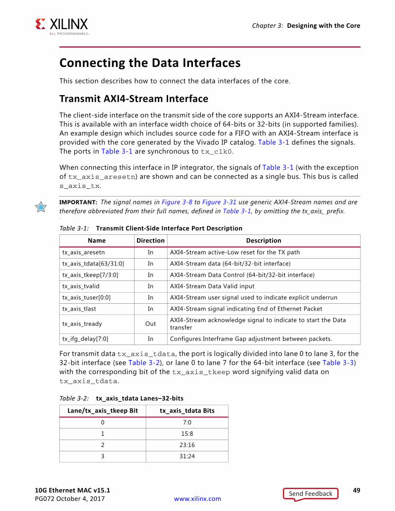
10G Ethernet MAC v15.1 49PG072 October 4, 2017 www.xilinx.com
Chapter 3: Designing with the Core
Connecting the Data InterfacesThis section describes how to connect the data interfaces of the core.
Transmit AXI4-Stream InterfaceThe client-side interface on the transmit side of the core supports an AXI4-Stream interface. This is available with an interface width choice of 64-bits or 32-bits (in supported families). An example design which includes source code for a FIFO with an AXI4-Stream interface is provided with the core generated by the Vivado IP catalog. Table 3-1 defines the signals. The ports in Table 3-1 are synchronous to tx_clk0.
When connecting this interface in IP integrator, the signals of Table 3-1 (with the exception of tx_axis_aresetn) are shown and can be connected as a single bus. This bus is called s_axis_tx.
IMPORTANT: The signal names in Figure 3-8 to Figure 3-31 use generic AXI4-Stream names and are therefore abbreviated from their full names, defined in Table 3-1, by omitting the tx_axis_ prefix.
For transmit data tx_axis_tdata, the port is logically divided into lane 0 to lane 3, for the 32-bit interface (see Table 3-2), or lane 0 to lane 7 for the 64-bit interface (see Table 3-3) with the corresponding bit of the tx_axis_tkeep word signifying valid data on tx_axis_tdata.
Table 3-1: Transmit Client-Side Interface Port Description
Name Direction Description
tx_axis_aresetn In AXI4-Stream active-Low reset for the TX path
tx_axis_tdata[63/31:0] In AXI4-Stream data (64-bit/32-bit interface)
tx_axis_tkeep[7/3:0] In AXI4-Stream Data Control (64-bit/32-bit interface)
tx_axis_tvalid In AXI4-Stream Data Valid input
tx_axis_tuser[0:0] In AXI4-Stream user signal used to indicate explicit underrun
tx_axis_tlast In AXI4-Stream signal indicating End of Ethernet Packet
tx_axis_tready Out AXI4-Stream acknowledge signal to indicate to start the Data transfer
tx_ifg_delay[7:0] In Configures Interframe Gap adjustment between packets.
Table 3-2: tx_axis_tdata Lanes–32-bits
Lane/tx_axis_tkeep Bit tx_axis_tdata Bits
0 7:0
1 15:8
2 23:16
3 31:24
Send Feedback

10G Ethernet MAC v15.1 50PG072 October 4, 2017 www.xilinx.com
Chapter 3: Designing with the Core
The definitions of the abbreviations used in the timing diagrams are described in Table 3-4.
Normal Frame Transmission
The timing of a normal frame transfer is shown in Figure 3-8 and Figure 3-9. When the client wants to transmit a frame, it asserts the tx_axis_tvalid and places the data and control in tx_axis_tdata and tx_axis_tkeep in the same clock cycle. When this data is accepted by the core, indicated by tx_axis_tready being asserted, the client must provide the next cycle of data. If tx_axis_tready is not asserted by the core then the client must hold the current valid data value until it is. The end of packet is indicated to the core by tx_axis_tlast asserted for 1 cycle. The bits of tx_axis_tkeep are set appropriately to indicate the number of valid bytes in the final data transfer. For example, in Figure 3-8, the first packet ends at Lane 1 and any data after that is ignored.
After tx_axis_tlast is deasserted, any data and control is deemed invalid until tx_axis_tvalid is next asserted. The clock for Figure 3-8 and Figure 3-9 is tx_clk0.
Table 3-3: tx_axis_tdata Lanes–64-bits
Lane/tx_axis_tkeep Bit tx_axis_tdata Bits
0 7:0
1 15:8
2 23:16
3 31:24
4 39:32
5 47:40
6 55:48
7 63:56
Table 3-4: Abbreviations Used in Timing Diagrams
Abbreviation Definition
DA Destination address
SA Source address
L/T Length/type field
FCS Frame check sequence (CRC)
Send Feedback
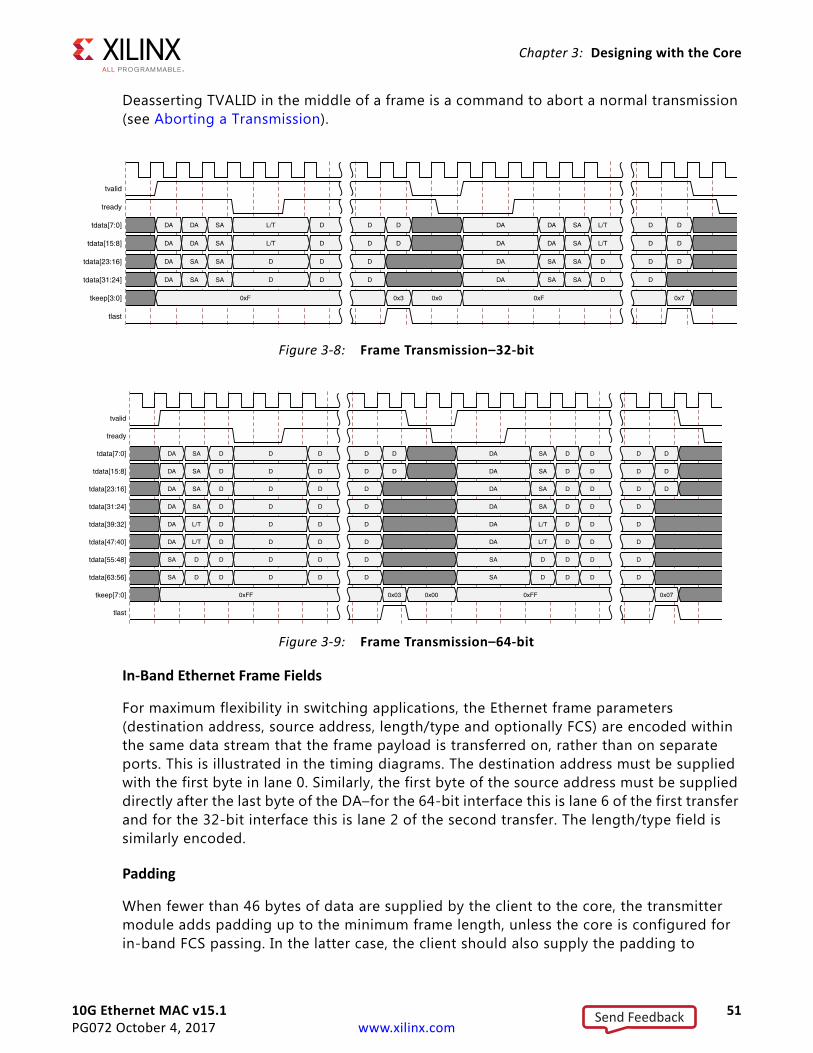
10G Ethernet MAC v15.1 51PG072 October 4, 2017 www.xilinx.com
Chapter 3: Designing with the Core
Deasserting TVALID in the middle of a frame is a command to abort a normal transmission (see Aborting a Transmission).
In-Band Ethernet Frame Fields
For maximum flexibility in switching applications, the Ethernet frame parameters (destination address, source address, length/type and optionally FCS) are encoded within the same data stream that the frame payload is transferred on, rather than on separate ports. This is illustrated in the timing diagrams. The destination address must be supplied with the first byte in lane 0. Similarly, the first byte of the source address must be supplied directly after the last byte of the DA–for the 64-bit interface this is lane 6 of the first transfer and for the 32-bit interface this is lane 2 of the second transfer. The length/type field is similarly encoded.
Padding
When fewer than 46 bytes of data are supplied by the client to the core, the transmitter module adds padding up to the minimum frame length, unless the core is configured for in-band FCS passing. In the latter case, the client should also supply the padding to
X-Ref Target - Figure 3-8
Figure 3-8: Frame Transmission–32-bit
X-Ref Target - Figure 3-9
Figure 3-9: Frame Transmission–64-bit
Send Feedback
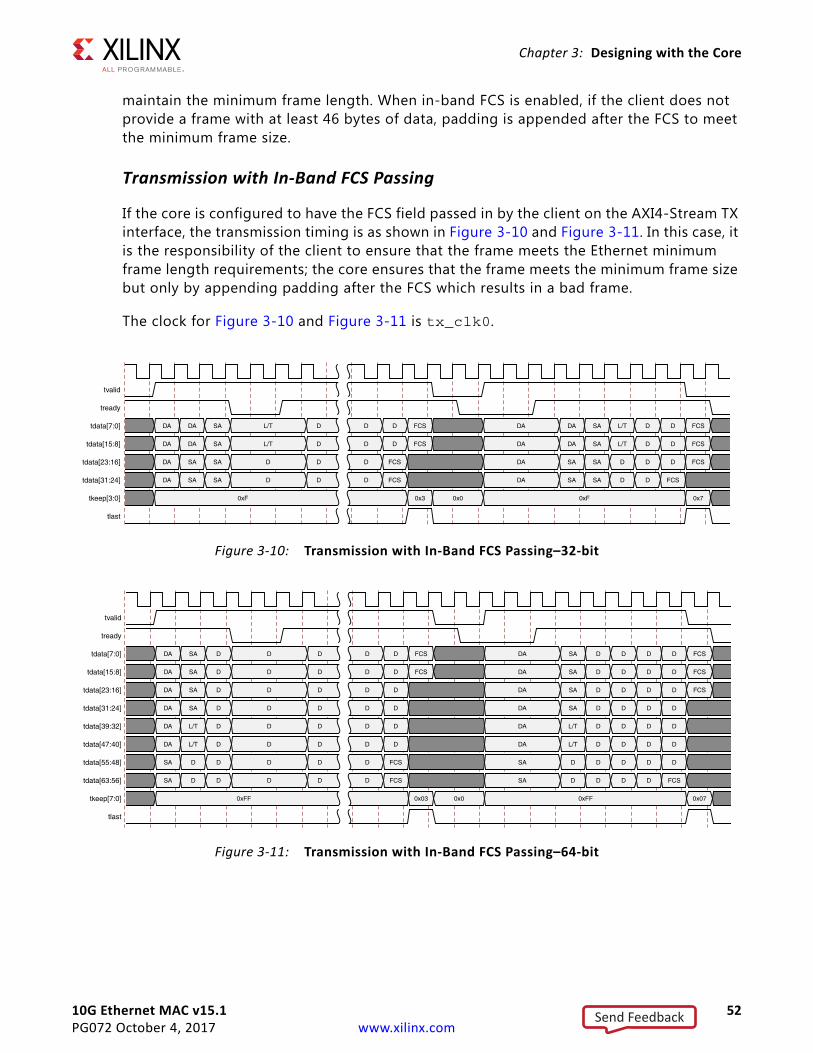
10G Ethernet MAC v15.1 52PG072 October 4, 2017 www.xilinx.com
Chapter 3: Designing with the Core
maintain the minimum frame length. When in-band FCS is enabled, if the client does not provide a frame with at least 46 bytes of data, padding is appended after the FCS to meet the minimum frame size.
Transmission with In-Band FCS Passing
If the core is configured to have the FCS field passed in by the client on the AXI4-Stream TX interface, the transmission timing is as shown in Figure 3-10 and Figure 3-11. In this case, it is the responsibility of the client to ensure that the frame meets the Ethernet minimum frame length requirements; the core ensures that the frame meets the minimum frame size but only by appending padding after the FCS which results in a bad frame.
The clock for Figure 3-10 and Figure 3-11 is tx_clk0.
X-Ref Target - Figure 3-10
Figure 3-10: Transmission with In-Band FCS Passing–32-bit
X-Ref Target - Figure 3-11
Figure 3-11: Transmission with In-Band FCS Passing–64-bit
Send Feedback
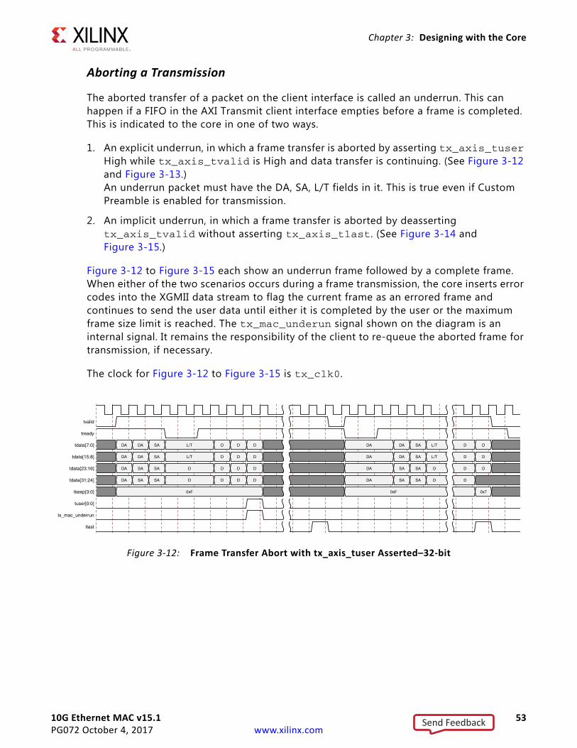
10G Ethernet MAC v15.1 53PG072 October 4, 2017 www.xilinx.com
Chapter 3: Designing with the Core
Aborting a Transmission
The aborted transfer of a packet on the client interface is called an underrun. This can happen if a FIFO in the AXI Transmit client interface empties before a frame is completed. This is indicated to the core in one of two ways.
1. An explicit underrun, in which a frame transfer is aborted by asserting tx_axis_tuser High while tx_axis_tvalid is High and data transfer is continuing. (See Figure 3-12 and Figure 3-13.) An underrun packet must have the DA, SA, L/T fields in it. This is true even if Custom Preamble is enabled for transmission.
2. An implicit underrun, in which a frame transfer is aborted by deasserting tx_axis_tvalid without asserting tx_axis_tlast. (See Figure 3-14 and Figure 3-15.)
Figure 3-12 to Figure 3-15 each show an underrun frame followed by a complete frame. When either of the two scenarios occurs during a frame transmission, the core inserts error codes into the XGMII data stream to flag the current frame as an errored frame and continues to send the user data until either it is completed by the user or the maximum frame size limit is reached. The tx_mac_underun signal shown on the diagram is an internal signal. It remains the responsibility of the client to re-queue the aborted frame for transmission, if necessary.
The clock for Figure 3-12 to Figure 3-15 is tx_clk0.
X-Ref Target - Figure 3-12
Figure 3-12: Frame Transfer Abort with tx_axis_tuser Asserted–32-bit
Send Feedback
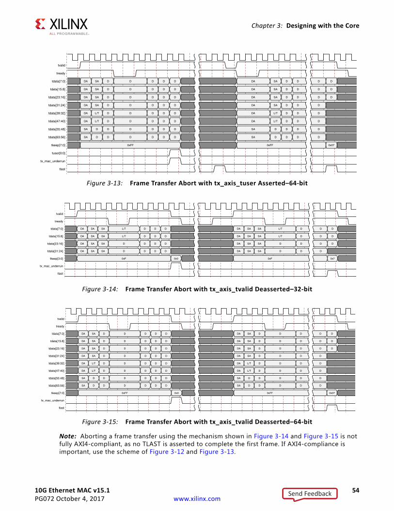
10G Ethernet MAC v15.1 54PG072 October 4, 2017 www.xilinx.com
Chapter 3: Designing with the Core
Note: Aborting a frame transfer using the mechanism shown in Figure 3-14 and Figure 3-15 is not fully AXI4-compliant, as no TLAST is asserted to complete the first frame. If AXI4-compliance is important, use the scheme of Figure 3-12 and Figure 3-13.
X-Ref Target - Figure 3-13
Figure 3-13: Frame Transfer Abort with tx_axis_tuser Asserted–64-bit
X-Ref Target - Figure 3-14
Figure 3-14: Frame Transfer Abort with tx_axis_tvalid Deasserted–32-bit
X-Ref Target - Figure 3-15
Figure 3-15: Frame Transfer Abort with tx_axis_tvalid Deasserted–64-bit
Send Feedback
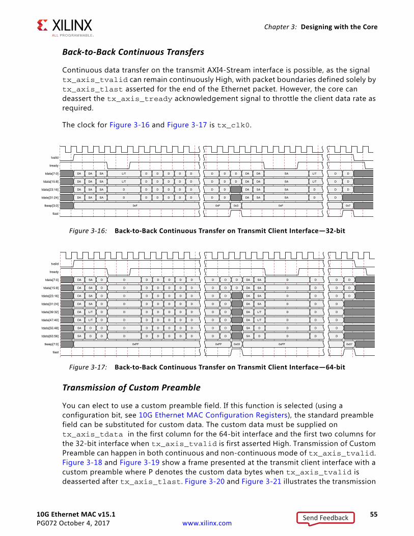
10G Ethernet MAC v15.1 55PG072 October 4, 2017 www.xilinx.com
Chapter 3: Designing with the Core
Back-to-Back Continuous Transfers
Continuous data transfer on the transmit AXI4-Stream interface is possible, as the signal tx_axis_tvalid can remain continuously High, with packet boundaries defined solely by tx_axis_tlast asserted for the end of the Ethernet packet. However, the core can deassert the tx_axis_tready acknowledgement signal to throttle the client data rate as required.
The clock for Figure 3-16 and Figure 3-17 is tx_clk0.
Transmission of Custom Preamble
You can elect to use a custom preamble field. If this function is selected (using a configuration bit, see 10G Ethernet MAC Configuration Registers), the standard preamble field can be substituted for custom data. The custom data must be supplied on tx_axis_tdata in the first column for the 64-bit interface and the first two columns for the 32-bit interface when tx_axis_tvalid is first asserted High. Transmission of Custom Preamble can happen in both continuous and non-continuous mode of tx_axis_tvalid. Figure 3-18 and Figure 3-19 show a frame presented at the transmit client interface with a custom preamble where P denotes the custom data bytes when tx_axis_tvalid is deasserted after tx_axis_tlast. Figure 3-20 and Figure 3-21 illustrates the transmission
X-Ref Target - Figure 3-16
Figure 3-16: Back-to-Back Continuous Transfer on Transmit Client Interface—32-bit
X-Ref Target - Figure 3-17
Figure 3-17: Back-to-Back Continuous Transfer on Transmit Client Interface—64-bit
Send Feedback
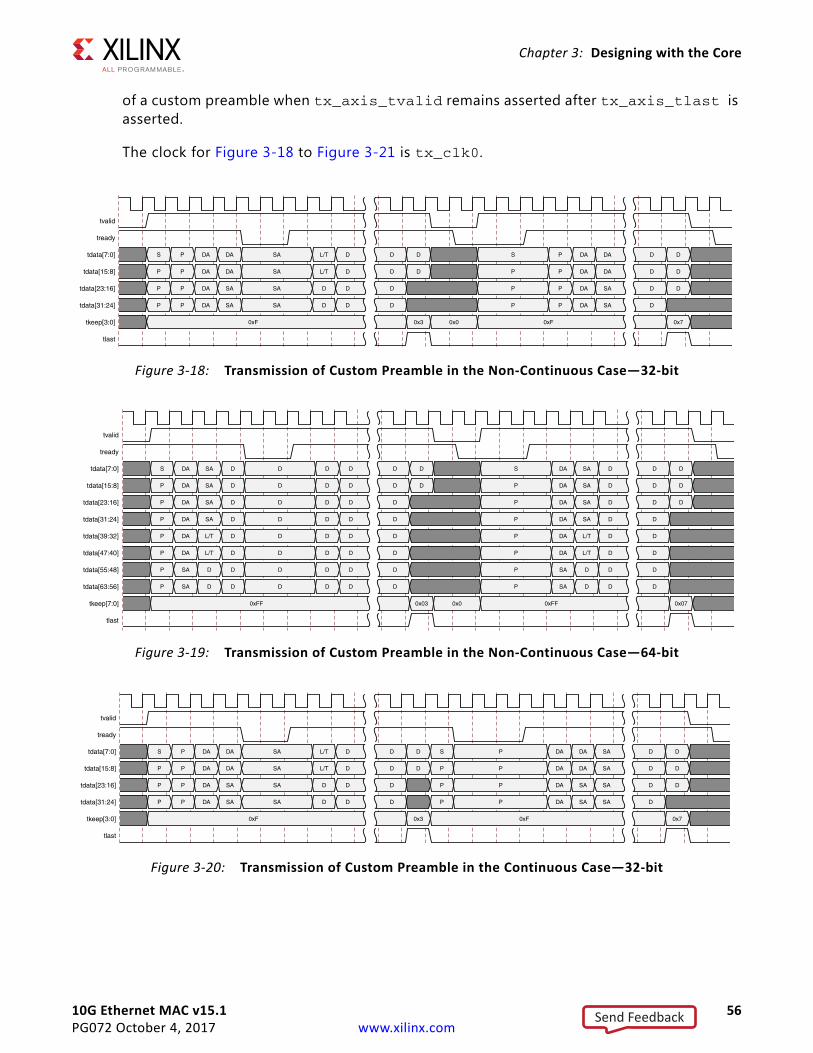
10G Ethernet MAC v15.1 56PG072 October 4, 2017 www.xilinx.com
Chapter 3: Designing with the Core
of a custom preamble when tx_axis_tvalid remains asserted after tx_axis_tlast is asserted.
The clock for Figure 3-18 to Figure 3-21 is tx_clk0.
X-Ref Target - Figure 3-18
Figure 3-18: Transmission of Custom Preamble in the Non-Continuous Case—32-bit
X-Ref Target - Figure 3-19
Figure 3-19: Transmission of Custom Preamble in the Non-Continuous Case—64-bit
X-Ref Target - Figure 3-20
Figure 3-20: Transmission of Custom Preamble in the Continuous Case—32-bit
Send Feedback
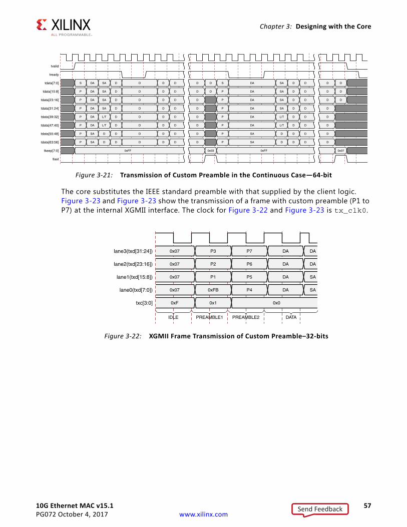
10G Ethernet MAC v15.1 57PG072 October 4, 2017 www.xilinx.com
Chapter 3: Designing with the Core
The core substitutes the IEEE standard preamble with that supplied by the client logic. Figure 3-23 and Figure 3-23 show the transmission of a frame with custom preamble (P1 to P7) at the internal XGMII interface. The clock for Figure 3-22 and Figure 3-23 is tx_clk0.
X-Ref Target - Figure 3-21
Figure 3-21: Transmission of Custom Preamble in the Continuous Case—64-bit
X-Ref Target - Figure 3-22
Figure 3-22: XGMII Frame Transmission of Custom Preamble–32-bits
Send Feedback
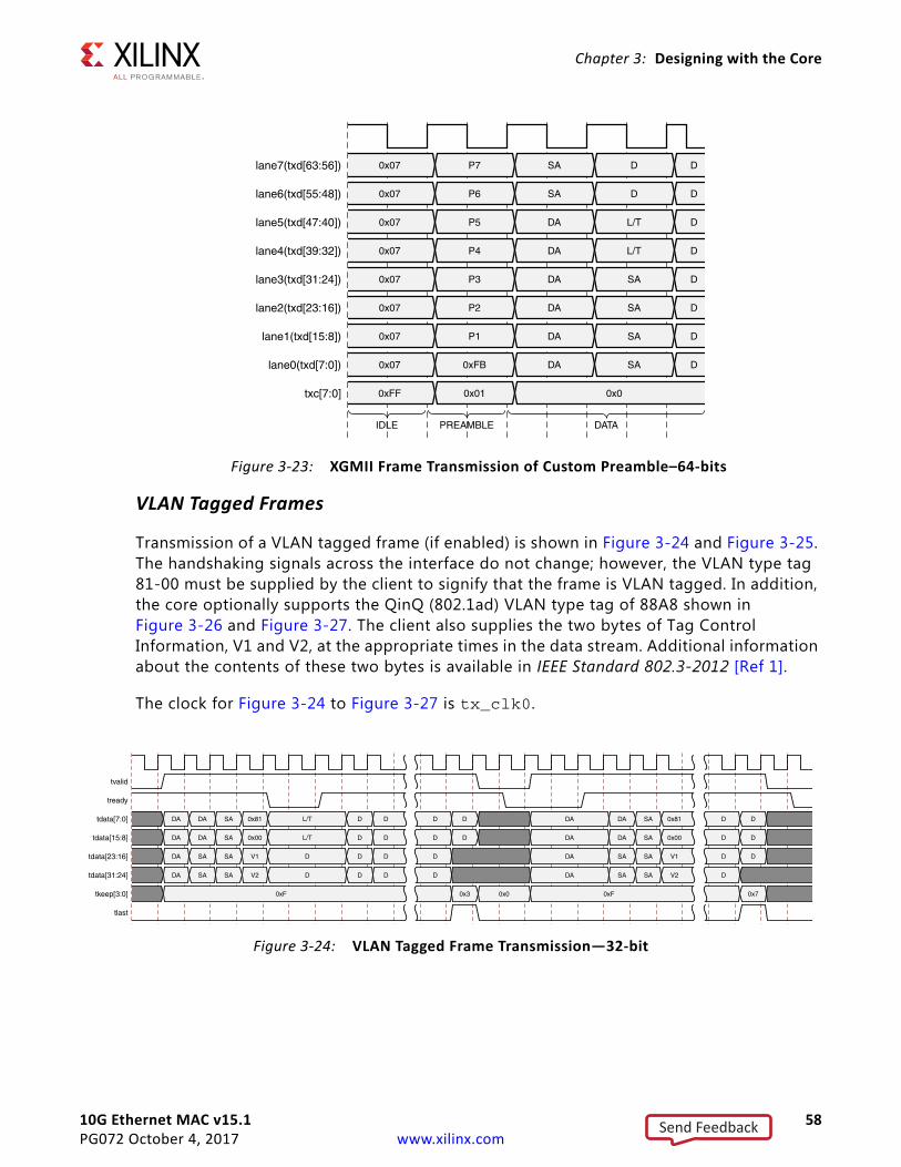
10G Ethernet MAC v15.1 58PG072 October 4, 2017 www.xilinx.com
Chapter 3: Designing with the Core
X-Ref Target - Figure 3-23.
VLAN Tagged Frames
Transmission of a VLAN tagged frame (if enabled) is shown in Figure 3-24 and Figure 3-25. The handshaking signals across the interface do not change; however, the VLAN type tag 81-00 must be supplied by the client to signify that the frame is VLAN tagged. In addition, the core optionally supports the QinQ (802.1ad) VLAN type tag of 88A8 shown in Figure 3-26 and Figure 3-27. The client also supplies the two bytes of Tag Control Information, V1 and V2, at the appropriate times in the data stream. Additional information about the contents of these two bytes is available in IEEE Standard 802.3-2012 [Ref 1].
The clock for Figure 3-24 to Figure 3-27 is tx_clk0.
Figure 3-23: XGMII Frame Transmission of Custom Preamble–64-bits
X-Ref Target - Figure 3-24
Figure 3-24: VLAN Tagged Frame Transmission—32-bit
Send Feedback
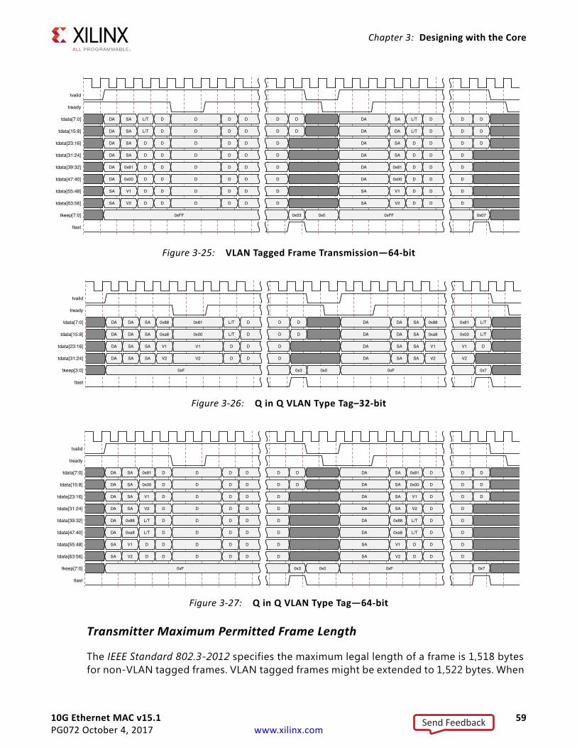
10G Ethernet MAC v15.1 59PG072 October 4, 2017 www.xilinx.com
Chapter 3: Designing with the Core
Transmitter Maximum Permitted Frame Length
The IEEE Standard 802.3-2012 specifies the maximum legal length of a frame is 1,518 bytes for non-VLAN tagged frames. VLAN tagged frames might be extended to 1,522 bytes. When
X-Ref Target - Figure 3-25
Figure 3-25: VLAN Tagged Frame Transmission—64-bit
X-Ref Target - Figure 3-26
Figure 3-26: Q in Q VLAN Type Tag–32-bit
X-Ref Target - Figure 3-27
Figure 3-27: Q in Q VLAN Type Tag—64-bit
Send Feedback
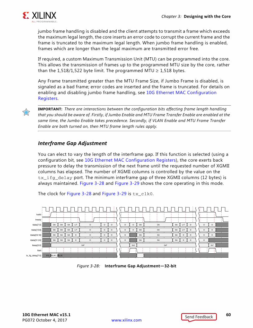
10G Ethernet MAC v15.1 60PG072 October 4, 2017 www.xilinx.com
Chapter 3: Designing with the Core
jumbo frame handling is disabled and the client attempts to transmit a frame which exceeds the maximum legal length, the core inserts an error code to corrupt the current frame and the frame is truncated to the maximum legal length. When jumbo frame handling is enabled, frames which are longer than the legal maximum are transmitted error free.
If required, a custom Maximum Transmission Unit (MTU) can be programmed into the core. This allows the transmission of frames up to the programmed MTU size by the core, rather than the 1,518/1,522 byte limit. The programmed MTU ≥ 1,518 bytes.
Any Frame transmitted greater than the MTU Frame Size, if Jumbo Frame is disabled, is signaled as a bad frame; error codes are inserted and the frame is truncated. For details on enabling and disabling jumbo frame handling, see 10G Ethernet MAC Configuration Registers.
IMPORTANT: There are interactions between the configuration bits affecting frame length handling that you should be aware of. Firstly, if Jumbo Enable and MTU Frame Transfer Enable are enabled at the same time, the Jumbo Enable takes precedence. Secondly, if VLAN Enable and MTU Frame Transfer Enable are both turned on, then MTU frame length rules apply.
Interframe Gap Adjustment
You can elect to vary the length of the interframe gap. If this function is selected (using a configuration bit, see 10G Ethernet MAC Configuration Registers), the core exerts back pressure to delay the transmission of the next frame until the requested number of XGMII columns has elapsed. The number of XGMII columns is controlled by the value on the tx_ifg_delay port. The minimum interframe gap of three XGMII columns (12 bytes) is always maintained. Figure 3-28 and Figure 3-29 shows the core operating in this mode.
The clock for Figure 3-28 and Figure 3-29 is tx_clk0.
X-Ref Target - Figure 3-28
Figure 3-28: Interframe Gap Adjustment—32-bit
Send Feedback
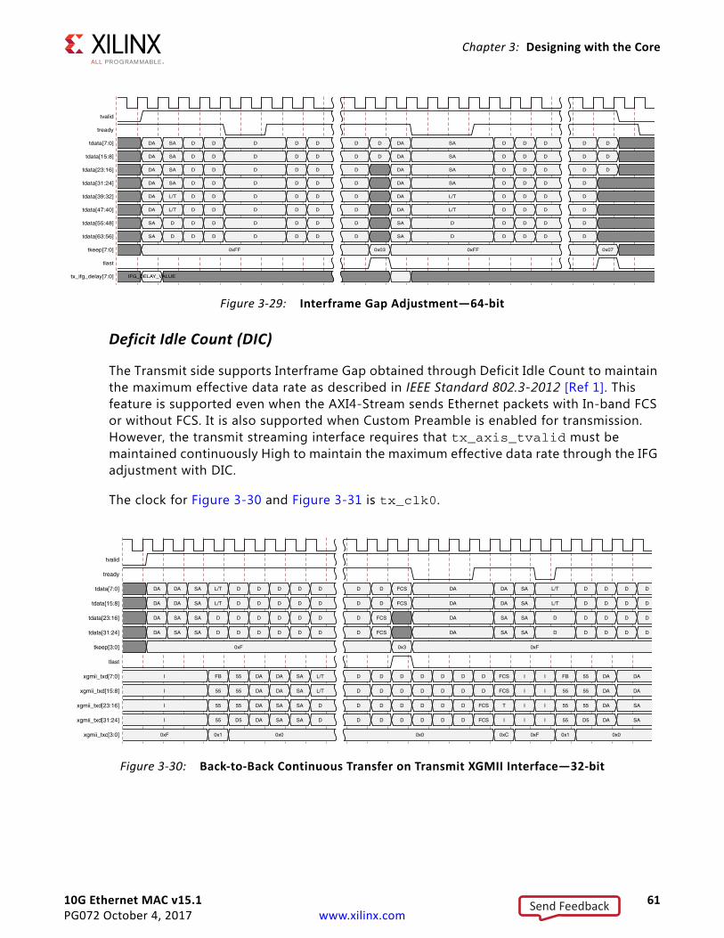
10G Ethernet MAC v15.1 61PG072 October 4, 2017 www.xilinx.com
Chapter 3: Designing with the Core
Deficit Idle Count (DIC)
The Transmit side supports Interframe Gap obtained through Deficit Idle Count to maintain the maximum effective data rate as described in IEEE Standard 802.3-2012 [Ref 1]. This feature is supported even when the AXI4-Stream sends Ethernet packets with In-band FCS or without FCS. It is also supported when Custom Preamble is enabled for transmission. However, the transmit streaming interface requires that tx_axis_tvalid must be maintained continuously High to maintain the maximum effective data rate through the IFG adjustment with DIC.
The clock for Figure 3-30 and Figure 3-31 is tx_clk0.
X-Ref Target - Figure 3-29
Figure 3-29: Interframe Gap Adjustment—64-bit
X-Ref Target - Figure 3-30
Figure 3-30: Back-to-Back Continuous Transfer on Transmit XGMII Interface—32-bit
Send Feedback
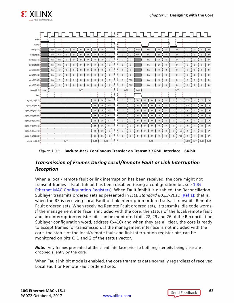
10G Ethernet MAC v15.1 62PG072 October 4, 2017 www.xilinx.com
Chapter 3: Designing with the Core
Transmission of Frames During Local/Remote Fault or Link Interruption Reception
When a local/ remote fault or link interruption has been received, the core might not transmit frames if Fault Inhibit has been disabled (using a configuration bit, see 10G Ethernet MAC Configuration Registers). When Fault Inhibit is disabled, the Reconciliation Sublayer transmits ordered sets as presented in IEEE Standard 802.3-2012 [Ref 1]; that is, when the RS is receiving Local Fault or link interruption ordered sets, it transmits Remote Fault ordered sets. When receiving Remote Fault ordered sets, it transmits idle code words. If the management interface is included with the core, the status of the local/remote fault and link interruption register bits can be monitored (bits 28, 29 and 26 of the Reconciliation Sublayer configuration word, address 0x410) and when they are all clear, the core is ready to accept frames for transmission. If the management interface is not included with the core, the status of the local/remote fault and link interruption register bits can be monitored on bits 0, 1 and 2 of the status vector.
Note: Any frames presented at the client interface prior to both register bits being clear are dropped silently by the core.
When Fault Inhibit mode is enabled, the core transmits data normally regardless of received Local Fault or Remote Fault ordered sets.
X-Ref Target - Figure 3-31
Figure 3-31: Back-to-Back Continuous Transfer on Transmit XGMII Interface—64-bit
Send Feedback
10G Ethernet MAC v15.1 63PG072 October 4, 2017 www.xilinx.com
Chapter 3: Designing with the Core
Receive AXI4-Stream InterfaceThe receive client-side interface supports the AXI4-Stream interface. This is available with an interface width choice of 64-bits or 32-bits for 10 Gb/s (in supported families). If the 32-bit datapath is used then there are four control bits to delineate bytes within the 32-bit port. If the 64-bit datapath is used then there are eight control bits to delineate bytes within the 64-bit port. Additionally, there are signals to indicate to the user logic the validity of the previous frame received. Table 3-5 defines the signals.The ports in Table 3-5 are synchronous to rx_clk.
When connecting this interface in IP integrator, the signals of Table 3-5 (with the exception of rx_axis_aresetn) are shown and can be connected as a single bus. This is called m_axis_rx.
IMPORTANT: The signal names in Figure 3-32 to Figure 3-41 use generic AXI4-Stream names and are therefore abbreviated from their full names, defined in Table 3-5, by omitting the rx_axis_ prefix.
For the receive data port rx_axis_tdata, the port is logically divided into lane 0 to lane 3 for the 32-bit interface (see Table 3-6) and lane 0 to lane 7 for the 64-bit interface (see Table 3-7) with the corresponding bit of the rx_axis_tkeep word signifying valid data on the rx_axis_tdata.
Table 3-5: Receive Client-Side Interface Port Description
Name Direction Description
rx_axis_aresetn In AXI4-Stream active-Low reset for receive path
rx_axis_tdata[63/31:0] Out AXI4-Stream Data to upper layer
rx_axis_tkeep[7/3:0] Out AXI4-Stream Data Control to upper layer
rx_axis_tvalid Out AXI4-Stream Data Valid
rx_axis_tuser OutAXI4-Stream User Sideband interface
0 indicates a bad packet has been received.1 indicates a good packet has been received.
rx_axis_tlast Out AXI4-Stream signal indicating an end of packet
Table 3-6: rx_axis_tdata Lanes
Lane/rx_axis_tkeep Bit rx_axis_tdata Bits
0 7:0
1 15:8
2 23:16
3 31:24
Send Feedback
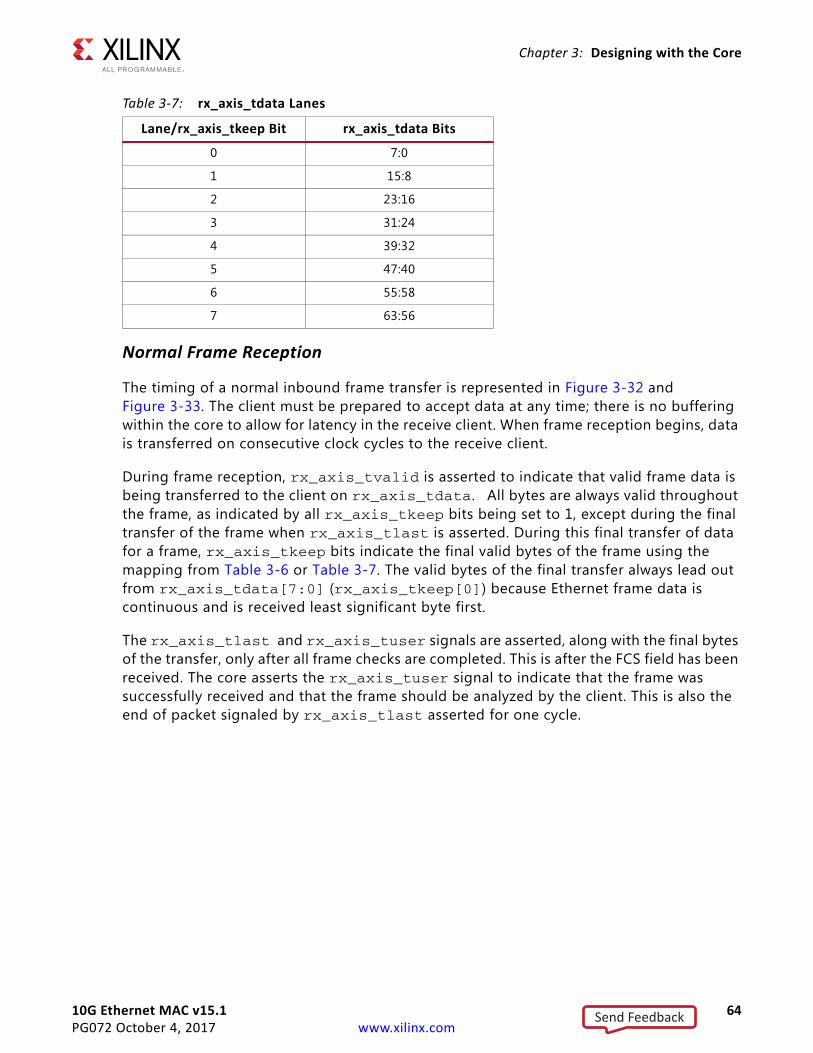
10G Ethernet MAC v15.1 64PG072 October 4, 2017 www.xilinx.com
Chapter 3: Designing with the Core
Normal Frame Reception
The timing of a normal inbound frame transfer is represented in Figure 3-32 and Figure 3-33. The client must be prepared to accept data at any time; there is no buffering within the core to allow for latency in the receive client. When frame reception begins, data is transferred on consecutive clock cycles to the receive client.
During frame reception, rx_axis_tvalid is asserted to indicate that valid frame data is being transferred to the client on rx_axis_tdata. All bytes are always valid throughout the frame, as indicated by all rx_axis_tkeep bits being set to 1, except during the final transfer of the frame when rx_axis_tlast is asserted. During this final transfer of data for a frame, rx_axis_tkeep bits indicate the final valid bytes of the frame using the mapping from Table 3-6 or Table 3-7. The valid bytes of the final transfer always lead out from rx_axis_tdata[7:0] (rx_axis_tkeep[0]) because Ethernet frame data is continuous and is received least significant byte first.
The rx_axis_tlast and rx_axis_tuser signals are asserted, along with the final bytes of the transfer, only after all frame checks are completed. This is after the FCS field has been received. The core asserts the rx_axis_tuser signal to indicate that the frame was successfully received and that the frame should be analyzed by the client. This is also the end of packet signaled by rx_axis_tlast asserted for one cycle.
Table 3-7: rx_axis_tdata Lanes
Lane/rx_axis_tkeep Bit rx_axis_tdata Bits
0 7:0
1 15:8
2 23:16
3 31:24
4 39:32
5 47:40
6 55:58
7 63:56
Send Feedback
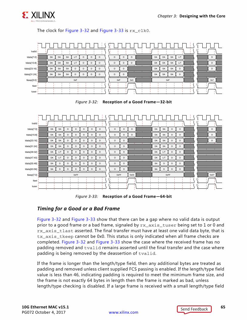
10G Ethernet MAC v15.1 65PG072 October 4, 2017 www.xilinx.com
Chapter 3: Designing with the Core
The clock for Figure 3-32 and Figure 3-33 is rx_clk0.
Timing for a Good or a Bad Frame
Figure 3-32 and Figure 3-33 show that there can be a gap where no valid data is output prior to a good frame or a bad frame, signaled by rx_axis_tuser being set to 1 or 0 and rx_axis_tlast asserted. The final transfer must have at least one valid data byte, that is tx_axis_tkeep cannot be 0x0. This status is only indicated when all frame checks are completed. Figure 3-32 and Figure 3-33 show the case where the received frame has no padding removed and tvalid remains asserted until the final transfer and the case where padding is being removed by the deassertion of tvalid.
If the frame is longer than the length/type field, then any additional bytes are treated as padding and removed unless client supplied FCS passing is enabled. If the length/type field value is less than 46, indicating padding is required to meet the mimimum frame size, and the frame is not exactly 64 bytes in length then the frame is marked as bad, unless length/type checking is disabled. If a large frame is received with a small length/type field
X-Ref Target - Figure 3-32
Figure 3-32: Reception of a Good Frame—32-bit
X-Ref Target - Figure 3-33
Figure 3-33: Reception of a Good Frame—64-bit
Send Feedback
10G Ethernet MAC v15.1 66PG072 October 4, 2017 www.xilinx.com
Chapter 3: Designing with the Core
value then this could result in a long delay between tvalid first being deasserted and the frame being marked as good or bad. Although good frame reception is illustrated, the same timing applies to a bad frame. Either the good frame or bad frame signaled through rx_axis_tuser and rx_axis_tlast is, however, always asserted before the next frame data begins to appear on rx_axis_tdata.
Frame Reception with Errors
The case of an unsuccessful frame reception (for example, a runt frame or a frame with an incorrect FCS) is shown in Figure 3-34 and Figure 3-35. In this case, the bad frame is received and the signal rx_axis_tuser is deasserted to the client at the end of the frame. It is then the responsibility of the client to drop the data already transferred for this frame.
The following conditions cause the assertion of rx_axis_tlast along with rx_axis_tuser = 0 signifying a bad_frame:
• FCS errors occur.
• Packets are shorter than 64 bytes (undersize or fragment frames).
• Jumbo frames are received when jumbo frames are not enabled.
• Frames of length greater than the MTU Size programmed are received, MTU Size Enable Frames are enabled, and jumbo frames are not enabled.
• The length/type field is length, in which the length value is less than 46. In this situation, the frame should be padded to minimum length. If it is not padded to exactly minimum frame length, the frame is marked as bad (when length/type checking is enabled).
• The length/type field is length, in which the length value is 46 or more, but the real length of the received frame does not match or exceed the value in the length/type field (when length/type checking is enabled).
• Any control frame that is received is not exactly the minimum frame length unless Control Frame Length Check Disable is set.
• The XGMII data stream contains error codes.
• A valid pause frame, addressed to the core, is received when flow control is enabled. This frame is only marked as an error because it has been used by the MAC flow control logic and has now served its purpose.
• A valid Priority Flow Control (PFC) frame, addressed to the core, is received when PFC is enabled. This frame is only marked as an error because it has been used by the MAC PFC logic and has now served its purpose.
Send Feedback
10G Ethernet MAC v15.1 67PG072 October 4, 2017 www.xilinx.com
Chapter 3: Designing with the Core
The clock for Figure 3-34 and Figure 3-35 is rx_clk0.
Reception with In-Band FCS Passing
Figure 3-36 and Figure 3-37 illustrates the core configured to pass the FCS field to the client (see 10G Ethernet MAC Configuration Registers). In this case, any padding inserted into the frame to meet the Ethernet minimum frame length specifications is left intact and passed to the client. Although the FCS is passed up to the client, it is also verified by the core, and rx_axis_tuser is 0 when rx_axis_tlast is asserted if the FCS check fails.
X-Ref Target - Figure 3-34
Figure 3-34: Frame Reception with Error—32-bit
X-Ref Target - Figure 3-35
Figure 3-35: Frame Reception with Error—64-bit
Send Feedback
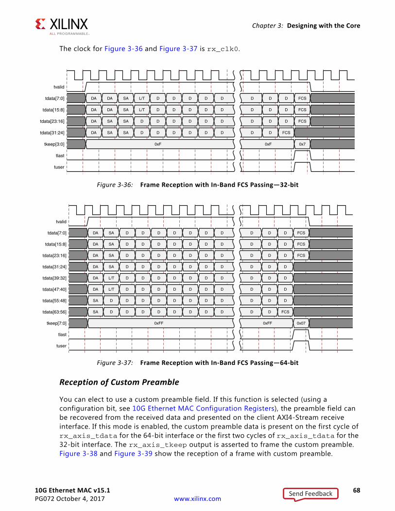
10G Ethernet MAC v15.1 68PG072 October 4, 2017 www.xilinx.com
Chapter 3: Designing with the Core
The clock for Figure 3-36 and Figure 3-37 is rx_clk0.
Reception of Custom Preamble
You can elect to use a custom preamble field. If this function is selected (using a configuration bit, see 10G Ethernet MAC Configuration Registers), the preamble field can be recovered from the received data and presented on the client AXI4-Stream receive interface. If this mode is enabled, the custom preamble data is present on the first cycle of rx_axis_tdata for the 64-bit interface or the first two cycles of rx_axis_tdata for the 32-bit interface. The rx_axis_tkeep output is asserted to frame the custom preamble. Figure 3-38 and Figure 3-39 show the reception of a frame with custom preamble.
X-Ref Target - Figure 3-36
Figure 3-36: Frame Reception with In-Band FCS Passing—32-bit
X-Ref Target - Figure 3-37
Figure 3-37: Frame Reception with In-Band FCS Passing—64-bit
Send Feedback
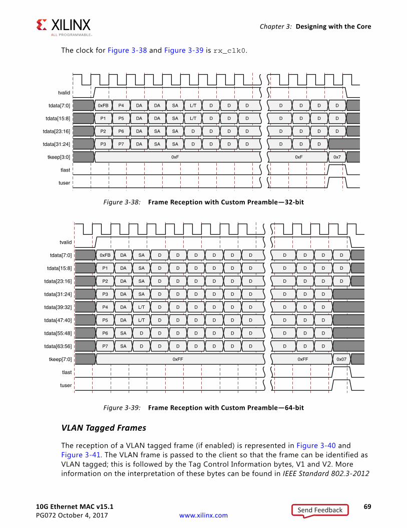
10G Ethernet MAC v15.1 69PG072 October 4, 2017 www.xilinx.com
Chapter 3: Designing with the Core
The clock for Figure 3-38 and Figure 3-39 is rx_clk0.
VLAN Tagged Frames
The reception of a VLAN tagged frame (if enabled) is represented in Figure 3-40 and Figure 3-41. The VLAN frame is passed to the client so that the frame can be identified as VLAN tagged; this is followed by the Tag Control Information bytes, V1 and V2. More information on the interpretation of these bytes can be found in IEEE Standard 802.3-2012
X-Ref Target - Figure 3-38
Figure 3-38: Frame Reception with Custom Preamble—32-bit
X-Ref Target - Figure 3-39
Figure 3-39: Frame Reception with Custom Preamble—64-bit
Send Feedback
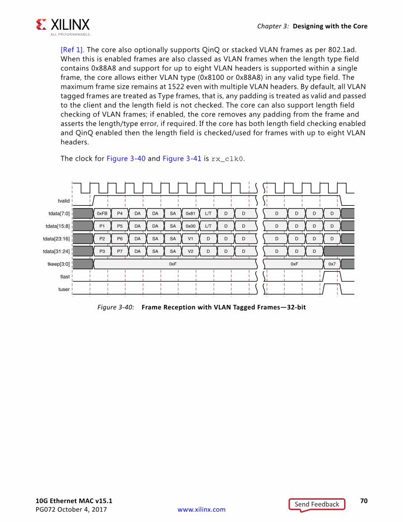
10G Ethernet MAC v15.1 70PG072 October 4, 2017 www.xilinx.com
Chapter 3: Designing with the Core
[Ref 1]. The core also optionally supports QinQ or stacked VLAN frames as per 802.1ad. When this is enabled frames are also classed as VLAN frames when the length type field contains 0x88A8 and support for up to eight VLAN headers is supported within a single frame, the core allows either VLAN type (0x8100 or 0x88A8) in any valid type field. The maximum frame size remains at 1522 even with multiple VLAN headers. By default, all VLAN tagged frames are treated as Type frames, that is, any padding is treated as valid and passed to the client and the length field is not checked. The core can also support length field checking of VLAN frames; if enabled, the core removes any padding from the frame and asserts the length/type error, if required. If the core has both length field checking enabled and QinQ enabled then the length field is checked/used for frames with up to eight VLAN headers.
The clock for Figure 3-40 and Figure 3-41 is rx_clk0.
X-Ref Target - Figure 3-40
Figure 3-40: Frame Reception with VLAN Tagged Frames—32-bit
Send Feedback
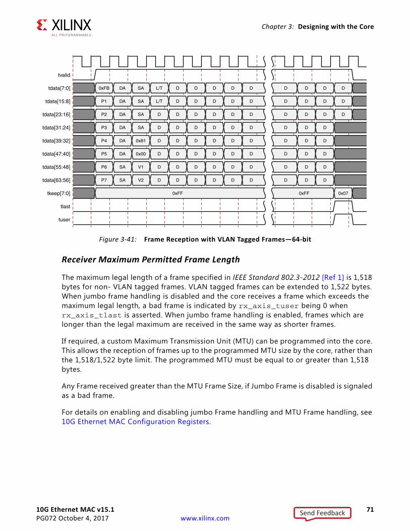
10G Ethernet MAC v15.1 71PG072 October 4, 2017 www.xilinx.com
Chapter 3: Designing with the Core
Receiver Maximum Permitted Frame Length
The maximum legal length of a frame specified in IEEE Standard 802.3-2012 [Ref 1] is 1,518 bytes for non- VLAN tagged frames. VLAN tagged frames can be extended to 1,522 bytes. When jumbo frame handling is disabled and the core receives a frame which exceeds the maximum legal length, a bad frame is indicated by rx_axis_tuser being 0 when rx_axis_tlast is asserted. When jumbo frame handling is enabled, frames which are longer than the legal maximum are received in the same way as shorter frames.
If required, a custom Maximum Transmission Unit (MTU) can be programmed into the core. This allows the reception of frames up to the programmed MTU size by the core, rather than the 1,518/1,522 byte limit. The programmed MTU must be equal to or greater than 1,518 bytes.
Any Frame received greater than the MTU Frame Size, if Jumbo Frame is disabled is signaled as a bad frame.
For details on enabling and disabling jumbo Frame handling and MTU Frame handling, see 10G Ethernet MAC Configuration Registers.
X-Ref Target - Figure 3-41
Figure 3-41: Frame Reception with VLAN Tagged Frames—64-bit
Send Feedback
10G Ethernet MAC v15.1 72PG072 October 4, 2017 www.xilinx.com
Chapter 3: Designing with the Core
Length/Type Field Error Checks
Enabled
Default operation is with the length/type error checking enabled (see 10G Ethernet MAC Configuration Registers). In this mode the following checks are made on all received, non VLAN-tagged, frames. If either of these checks fail, the frame is marked as bad. If a frame is a control frame or has a VLAN tag and enhanced VLAN support is not enabled, this check is not performed.
• A value in the length/type field which is ≥ decimal 46, but less than 1,536, is checked against the actual data length received.
• A value in the length/type field that is less than decimal 46, (a length interpretation), the frame data length is checked to see if it has been padded to exactly 46 bytes (so that the resultant total frame length is 64 bytes).
Furthermore, if padding is indicated (the length/type field is less than decimal 46) and client-supplied FCS passing is disabled, the length value in the length/type field is used to deassert rx_axis_tvalid after the indicated number of data bytes so that the padding bytes are removed from the frame. See Reception with In-Band FCS Passing.
Disabled
When the length/type error checking is disabled and the length/type field has a length interpretation, the core does not check the length value against the actual data length received as detailed previously. A frame containing only this error is marked as good. However, if the length/type field is less than decimal 46, the core marks a frame as bad if it is not the minimum frame size of 64 bytes.
If padding is indicated and client-supplied FCS passing is disabled, then a length value in the length/type field is not used to deassert rx_axis_tkeep[]. Instead, rx_axis_tkeep[] is deasserted before the start of the FCS field, and any padding is not removed from the frame.
PHY-Side InterfaceExternal XGMII versus Internal 64-Bit Interfaces (64-bit Datapath)
In the Vivado IDE, you can select a 32-bit DDR XGMII PHY interface or no interface, which is a 64-bit SDR interface intended for internal connection. In either case, the core internals are the same; only the interface changes, with the I/O registers and associated constraints targeting DDR or SDR operation, respectively.
Remember that although a frame to be transmitted should always be presented to the core with the start in lane 0; due to internal realignment, the start of the frame /S/ codeword might appear on the PHY side interface in lane 0 or lane 4. Likewise, the /S/ codeword might legally arrive at the RX PHY interface in either lane 0 or lane 4, but the core always presents it to the client logic with start of frame in lane 0.
Send Feedback
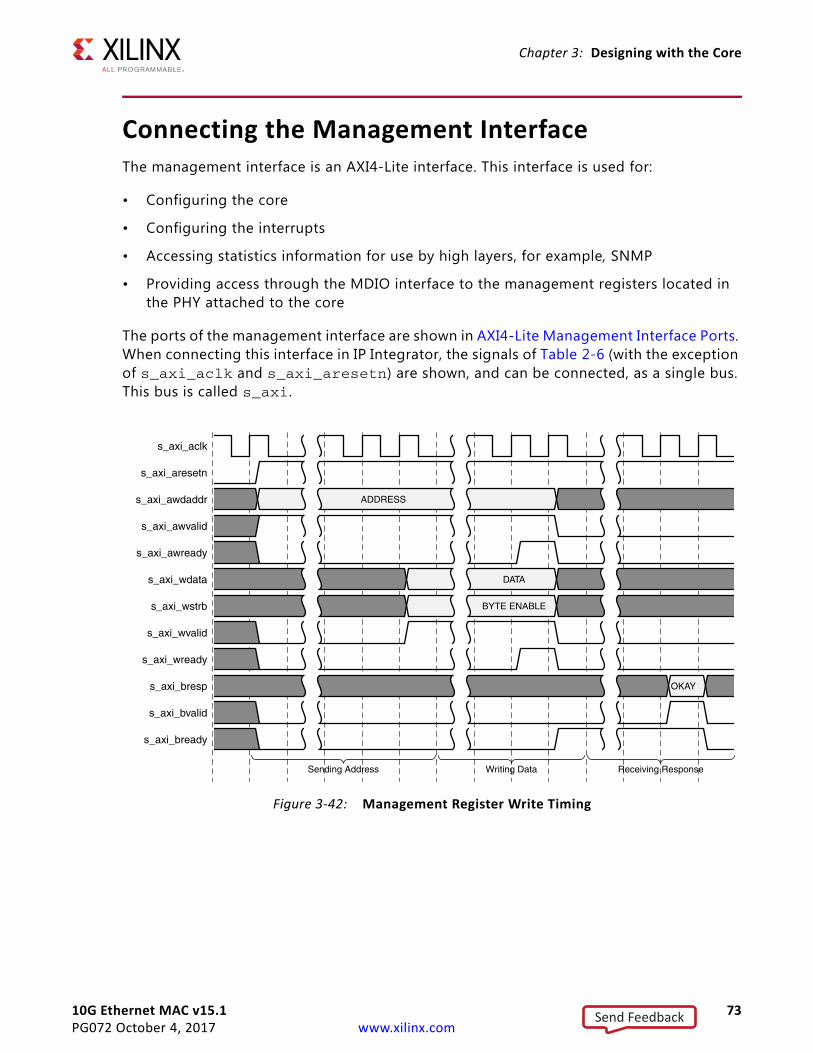
10G Ethernet MAC v15.1 73PG072 October 4, 2017 www.xilinx.com
Chapter 3: Designing with the Core
Connecting the Management InterfaceThe management interface is an AXI4-Lite interface. This interface is used for:
• Configuring the core
• Configuring the interrupts
• Accessing statistics information for use by high layers, for example, SNMP
• Providing access through the MDIO interface to the management registers located in the PHY attached to the core
The ports of the management interface are shown in AXI4-Lite Management Interface Ports. When connecting this interface in IP Integrator, the signals of Table 2-6 (with the exception of s_axi_aclk and s_axi_aresetn) are shown, and can be connected, as a single bus. This bus is called s_axi.
X-Ref Target - Figure 3-42
Figure 3-42: Management Register Write Timing
Send Feedback
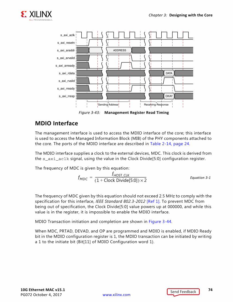
10G Ethernet MAC v15.1 74PG072 October 4, 2017 www.xilinx.com
Chapter 3: Designing with the Core
MDIO InterfaceThe management interface is used to access the MDIO interface of the core; this interface is used to access the Managed Information Block (MIB) of the PHY components attached to the core. The ports of the MDIO interface are described in Table 2-14, page 24.
The MDIO interface supplies a clock to the external devices, MDC. This clock is derived from the s_axi_aclk signal, using the value in the Clock Divide[5:0] configuration register.
The frequency of MDC is given by this equation:
Equation 3-1
The frequency of MDC given by this equation should not exceed 2.5 MHz to comply with the specification for this interface, IEEE Standard 802.3-2012 [Ref 1]. To prevent MDC from being out of specification, the Clock Divide[5:0] value powers up at 000000, and while this value is in the register, it is impossible to enable the MDIO interface.
MDIO Transaction initiation and completion are shown in Figure 3-44.
When MDC, PRTAD, DEVAD, and OP are programmed and MDIO is enabled, if MDIO Ready bit in the MDIO configuration register is 1, the MDIO transaction can be initiated by writing a 1 to the initiate bit (Bit[11] of MDIO Configuration word 1).
X-Ref Target - Figure 3-43
Figure 3-43: Management Register Read Timing
fMDCfHOST_CLK
1 Clock Divide[5:0]+( ) 2×--------------------------------------------------------=
Send Feedback
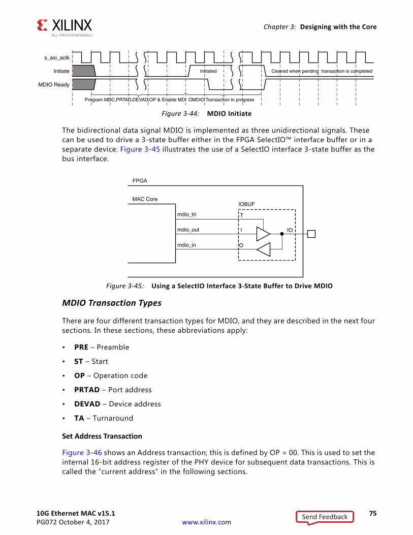
10G Ethernet MAC v15.1 75PG072 October 4, 2017 www.xilinx.com
Chapter 3: Designing with the Core
The bidirectional data signal MDIO is implemented as three unidirectional signals. These can be used to drive a 3-state buffer either in the FPGA SelectIO™ interface buffer or in a separate device. Figure 3-45 illustrates the use of a SelectIO interface 3-state buffer as the bus interface.
MDIO Transaction Types
There are four different transaction types for MDIO, and they are described in the next four sections. In these sections, these abbreviations apply:
• PRE – Preamble
• ST – Start
• OP – Operation code
• PRTAD – Port address
• DEVAD – Device address
• TA – Turnaround
Set Address Transaction
Figure 3-46 shows an Address transaction; this is defined by OP = 00. This is used to set the internal 16-bit address register of the PHY device for subsequent data transactions. This is called the “current address” in the following sections.
X-Ref Target - Figure 3-44
Figure 3-44: MDIO Initiate
X-Ref Target - Figure 3-45
Figure 3-45: Using a SelectIO Interface 3-State Buffer to Drive MDIO
Send Feedback
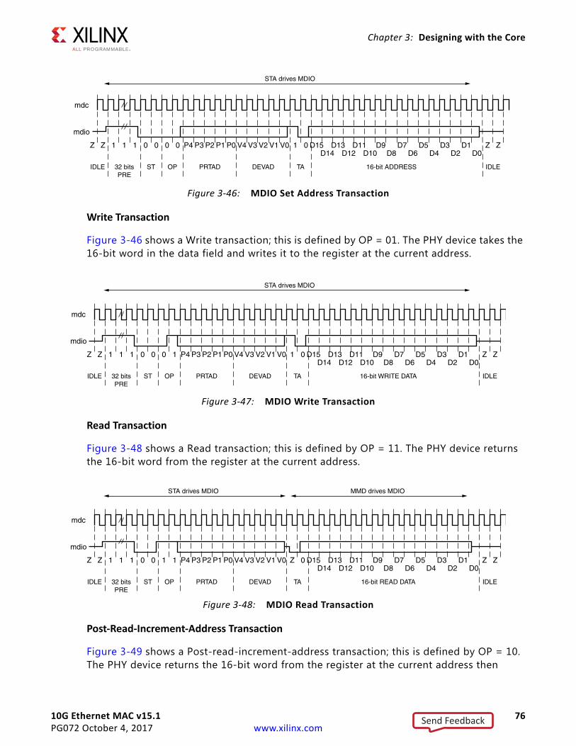
10G Ethernet MAC v15.1 76PG072 October 4, 2017 www.xilinx.com
Chapter 3: Designing with the Core
Write Transaction
Figure 3-46 shows a Write transaction; this is defined by OP = 01. The PHY device takes the 16-bit word in the data field and writes it to the register at the current address.
Read Transaction
Figure 3-48 shows a Read transaction; this is defined by OP = 11. The PHY device returns the 16-bit word from the register at the current address.
Post-Read-Increment-Address Transaction
Figure 3-49 shows a Post-read-increment-address transaction; this is defined by OP = 10. The PHY device returns the 16-bit word from the register at the current address then
X-Ref Target - Figure 3-46
Figure 3-46: MDIO Set Address Transaction
X-Ref Target - Figure 3-47
Figure 3-47: MDIO Write Transaction
X-Ref Target - Figure 3-48
Figure 3-48: MDIO Read Transaction
Send Feedback
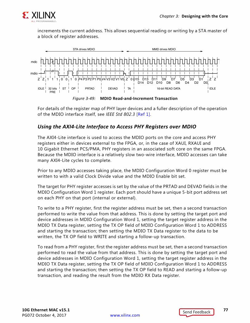
10G Ethernet MAC v15.1 77PG072 October 4, 2017 www.xilinx.com
Chapter 3: Designing with the Core
increments the current address. This allows sequential reading or writing by a STA master of a block of register addresses.
For details of the register map of PHY layer devices and a fuller description of the operation of the MDIO interface itself, see IEEE Std 802.3 [Ref 1].
Using the AXI4-Lite Interface to Access PHY Registers over MDIO
The AXI4-Lite interface is used to access the MDIO ports on the core and access PHY registers either in devices external to the FPGA, or, in the case of XAUI, RXAUI and 10 Gigabit Ethernet PCS/PMA, PHY registers in an associated soft core on the same FPGA. Because the MDIO interface is a relatively slow two-wire interface, MDIO accesses can take many AXI4-Lite cycles to complete.
Prior to any MDIO accesses taking place, the MDIO Configuration Word 0 register must be written to with a valid Clock Divide value and the MDIO Enable bit set.
The target for PHY register accesses is set by the value of the PRTAD and DEVAD fields in the MDIO Configuration Word 1 register. Each port should have a unique 5-bit port address set on each PHY on that port (internal or external).
To write to a PHY register, first the register address must be set, then a second transaction performed to write the value from that address. This is done by setting the target port and device addresses in MDIO Configuration Word 1, setting the target register address in the MDIO TX Data register, setting the TX OP field of MDIO Configuration Word 1 to ADDRESS and starting the transaction; then setting the MDIO TX Data register to the data to be written, the TX OP field to WRITE and starting a follow-up transaction.
To read from a PHY register, first the register address must be set, then a second transaction performed to read the value from that address. This is done by setting the target port and device addresses in MDIO Configuration Word 1, setting the target register address in the MDIO TX Data register, setting the TX OP field of MDIO Configuration Word 1 to ADDRESS and starting the transaction; then setting the TX OP field to READ and starting a follow-up transaction, and reading the result from the MDIO RX Data register.
X-Ref Target - Figure 3-49
Figure 3-49: MDIO Read-and-Increment Transaction
Send Feedback
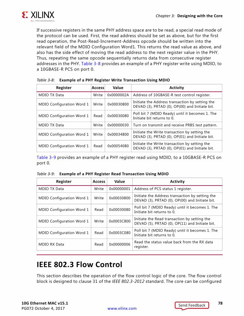
10G Ethernet MAC v15.1 78PG072 October 4, 2017 www.xilinx.com
Chapter 3: Designing with the Core
If successive registers in the same PHY address space are to be read, a special read mode of the protocol can be used. First, the read address should be set as above, but for the first read operation, the Post-Read-Increment-Address opcode should be written into the relevant field of the MDIO Configuration Word1. This returns the read value as above, and also has the side effect of moving the read address to the next register value in the PHY. Thus, repeating the same opcode sequentially returns data from consecutive register addresses in the PHY. Table 3-8 provides an example of a PHY register write using MDIO, to a 10GBASE-R PCS on port 0.
Table 3-9 provides an example of a PHY register read using MDIO, to a 10GBASE-R PCS on port 0.
IEEE 802.3 Flow ControlThis section describes the operation of the flow control logic of the core. The flow control block is designed to clause 31 of the IEEE 802.3-2012 standard. The core can be configured
Table 3-8: Example of a PHY Register Write Transaction Using MDIO
Register Access Value Activity
MDIO TX Data Write 0x0000002A Address of 10GBASE-R test control register.
MDIO Configuration Word 1 Write 0x00030800 Initiate the Address transaction by setting theDEVAD (3), PRTAD (0), OP(00) and Initiate bit.
MDIO Configuration Word 1 Read 0x00030080 Poll bit 7 (MDIO Ready) until it becomes 1. The Initiate bit returns to 0.
MDIO TX Data Write 0x00000030 Turn on transmit and receive PRBS test pattern.
MDIO Configuration Word 1 Write 0x00034800 Initiate the Write transaction by setting theDEVAD (3), PRTAD (0), OP(01) and Initiate bit.
MDIO Configuration Word 1 Read 0x00054080 Initiate the Write transaction by setting theDEVAD (3), PRTAD (0), OP(01) and Initiate bit.
Table 3-9: Example of a PHY Register Read Transaction Using MDIO
Register Access Value Activity
MDIO TX Data Write 0x00000001 Address of PCS status 1 register.
MDIO Configuration Word 1 Write 0x00030800 Initiate the Address transaction by setting the DEVAD (3), PRTAD (0), OP(00) and Initiate bit.
MDIO Configuration Word 1 Read 0x00030080 Poll bit 7 (MDIO Ready) until it becomes 1. The Initiate bit returns to 0.
MDIO Configuration Word 1 Write 0x0003C800 Initiate the Read transaction by setting the DEVAD (5), PRTAD (0), OP(11) and Initiate bit.
MDIO Configuration Word 1 Read 0x0003C080 Poll bit 7 (MDIO Ready) until it becomes 1. The Initiate bit returns to 0.
MDIO RX Data Read 0x00000006 Read the status value back from the RX data register.
Send Feedback
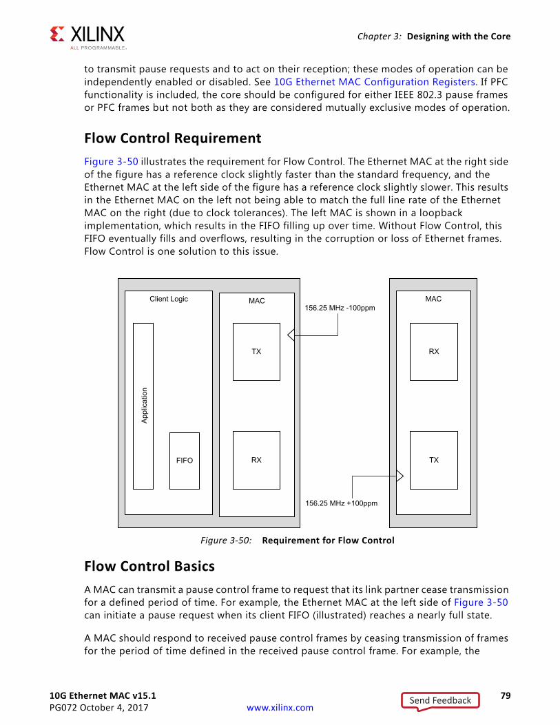
10G Ethernet MAC v15.1 79PG072 October 4, 2017 www.xilinx.com
Chapter 3: Designing with the Core
to transmit pause requests and to act on their reception; these modes of operation can be independently enabled or disabled. See 10G Ethernet MAC Configuration Registers. If PFC functionality is included, the core should be configured for either IEEE 802.3 pause frames or PFC frames but not both as they are considered mutually exclusive modes of operation.
Flow Control RequirementFigure 3-50 illustrates the requirement for Flow Control. The Ethernet MAC at the right side of the figure has a reference clock slightly faster than the standard frequency, and the Ethernet MAC at the left side of the figure has a reference clock slightly slower. This results in the Ethernet MAC on the left not being able to match the full line rate of the Ethernet MAC on the right (due to clock tolerances). The left MAC is shown in a loopback implementation, which results in the FIFO filling up over time. Without Flow Control, this FIFO eventually fills and overflows, resulting in the corruption or loss of Ethernet frames. Flow Control is one solution to this issue.
Flow Control BasicsA MAC can transmit a pause control frame to request that its link partner cease transmission for a defined period of time. For example, the Ethernet MAC at the left side of Figure 3-50 can initiate a pause request when its client FIFO (illustrated) reaches a nearly full state.
A MAC should respond to received pause control frames by ceasing transmission of frames for the period of time defined in the received pause control frame. For example, the
X-Ref Target - Figure 3-50
Figure 3-50: Requirement for Flow Control
Send Feedback
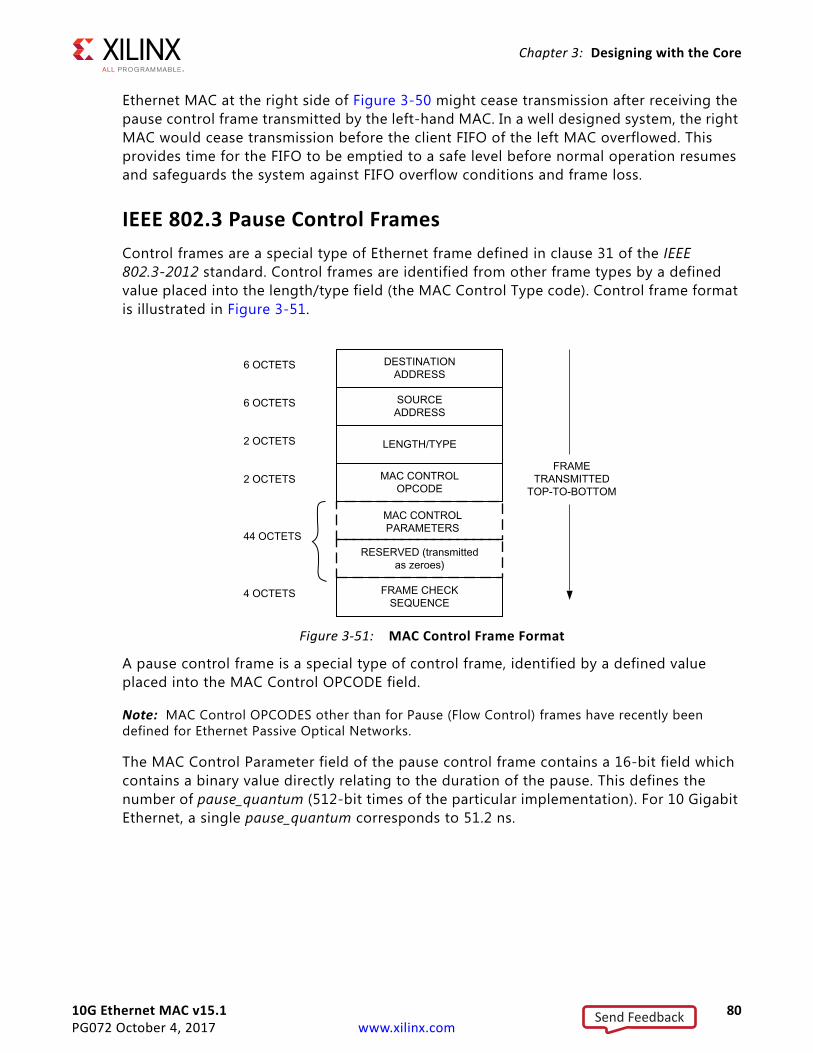
10G Ethernet MAC v15.1 80PG072 October 4, 2017 www.xilinx.com
Chapter 3: Designing with the Core
Ethernet MAC at the right side of Figure 3-50 might cease transmission after receiving the pause control frame transmitted by the left-hand MAC. In a well designed system, the right MAC would cease transmission before the client FIFO of the left MAC overflowed. This provides time for the FIFO to be emptied to a safe level before normal operation resumes and safeguards the system against FIFO overflow conditions and frame loss.
IEEE 802.3 Pause Control FramesControl frames are a special type of Ethernet frame defined in clause 31 of the IEEE 802.3-2012 standard. Control frames are identified from other frame types by a defined value placed into the length/type field (the MAC Control Type code). Control frame format is illustrated in Figure 3-51.
A pause control frame is a special type of control frame, identified by a defined value placed into the MAC Control OPCODE field.
Note: MAC Control OPCODES other than for Pause (Flow Control) frames have recently been defined for Ethernet Passive Optical Networks.
The MAC Control Parameter field of the pause control frame contains a 16-bit field which contains a binary value directly relating to the duration of the pause. This defines the number of pause_quantum (512-bit times of the particular implementation). For 10 Gigabit Ethernet, a single pause_quantum corresponds to 51.2 ns.
X-Ref Target - Figure 3-51
Figure 3-51: MAC Control Frame Format
Send Feedback
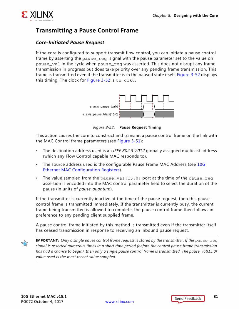
10G Ethernet MAC v15.1 81PG072 October 4, 2017 www.xilinx.com
Chapter 3: Designing with the Core
Transmitting a Pause Control Frame
Core-Initiated Pause Request
If the core is configured to support transmit flow control, you can initiate a pause control frame by asserting the pause_req signal with the pause parameter set to the value on pause_val in the cycle when pause_req was asserted. This does not disrupt any frame transmission in progress but does take priority over any pending frame transmission. This frame is transmitted even if the transmitter is in the paused state itself. Figure 3-52 displays this timing. The clock for Figure 3-52 is tx_clk0.
This action causes the core to construct and transmit a pause control frame on the link with the MAC Control frame parameters (see Figure 3-51):
• The destination address used is an IEEE 802.3-2012 globally assigned multicast address (which any Flow Control capable MAC responds to).
• The source address used is the configurable Pause Frame MAC Address (see 10G Ethernet MAC Configuration Registers).
• The value sampled from the pause_val[15:0] port at the time of the pause_req assertion is encoded into the MAC control parameter field to select the duration of the pause (in units of pause_quantum).
If the transmitter is currently inactive at the time of the pause request, then this pause control frame is transmitted immediately. If the transmitter is currently busy, the current frame being transmitted is allowed to complete; the pause control frame then follows in preference to any pending client supplied frame.
A pause control frame initiated by this method is transmitted even if the transmitter itself has ceased transmission in response to receiving an inbound pause request.
IMPORTANT: Only a single pause control frame request is stored by the transmitter. If the pause_req signal is asserted numerous times in a short time period (before the control pause frame transmission has had a chance to begin), then only a single pause control frame is transmitted. The pause_val[15:0] value used is the most recent value sampled.
X-Ref Target - Figure 3-52
Figure 3-52: Pause Request Timing
Send Feedback
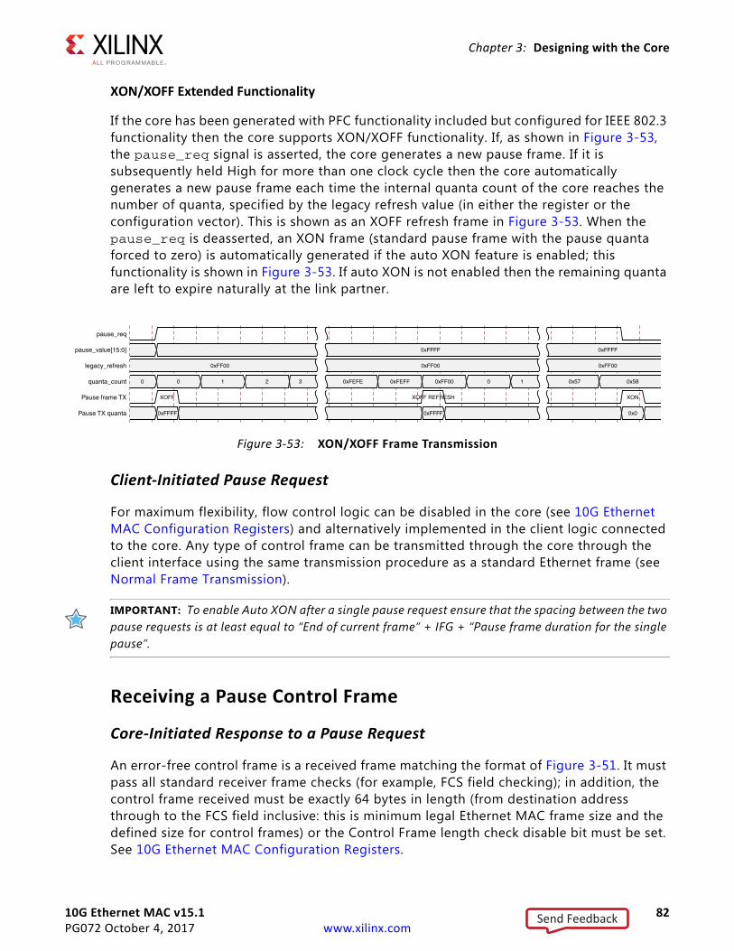
10G Ethernet MAC v15.1 82PG072 October 4, 2017 www.xilinx.com
Chapter 3: Designing with the Core
XON/XOFF Extended Functionality
If the core has been generated with PFC functionality included but configured for IEEE 802.3 functionality then the core supports XON/XOFF functionality. If, as shown in Figure 3-53, the pause_req signal is asserted, the core generates a new pause frame. If it is subsequently held High for more than one clock cycle then the core automatically generates a new pause frame each time the internal quanta count of the core reaches the number of quanta, specified by the legacy refresh value (in either the register or the configuration vector). This is shown as an XOFF refresh frame in Figure 3-53. When the pause_req is deasserted, an XON frame (standard pause frame with the pause quanta forced to zero) is automatically generated if the auto XON feature is enabled; this functionality is shown in Figure 3-53. If auto XON is not enabled then the remaining quanta are left to expire naturally at the link partner.
Client-Initiated Pause Request
For maximum flexibility, flow control logic can be disabled in the core (see 10G Ethernet MAC Configuration Registers) and alternatively implemented in the client logic connected to the core. Any type of control frame can be transmitted through the core through the client interface using the same transmission procedure as a standard Ethernet frame (see Normal Frame Transmission).
IMPORTANT: To enable Auto XON after a single pause request ensure that the spacing between the two pause requests is at least equal to “End of current frame” + IFG + “Pause frame duration for the single pause”.
Receiving a Pause Control Frame
Core-Initiated Response to a Pause Request
An error-free control frame is a received frame matching the format of Figure 3-51. It must pass all standard receiver frame checks (for example, FCS field checking); in addition, the control frame received must be exactly 64 bytes in length (from destination address through to the FCS field inclusive: this is minimum legal Ethernet MAC frame size and the defined size for control frames) or the Control Frame length check disable bit must be set. See 10G Ethernet MAC Configuration Registers.
X-Ref Target - Figure 3-53
Figure 3-53: XON/XOFF Frame Transmission
Send Feedback
10G Ethernet MAC v15.1 83PG072 October 4, 2017 www.xilinx.com
Chapter 3: Designing with the Core
Any control frame received that does not conform to these checks contains an error, and it is passed to the receiver client with the rx_axis_tuser deasserted when rx_axis_tlast is asserted to indicate a bad frame.
• Pause Frame Reception Disabled
When pause control reception is disabled (see 10G Ethernet MAC Configuration Registers), an error free control frame is received through the client interface with the rx_axis_tuser asserted when rx_axis_tlast is asserted to indicate a good frame. In this way, the frame is passed to the client logic for interpretation (see Client-Initiated Response to a Pause Request).
• Pause Frame Reception Enabled
When pause control reception is enabled (see 10G Ethernet MAC Configuration Registers) and an error-free frame is received by the core, the frame decoding functions are performed:
a. The destination address field is matched against the IEEE 802.3-2012 globally assigned multicast address or the configurable Pause Frame MAC Address (see 10G Ethernet MAC Configuration Registers).
b. The length/type field is matched against the MAC Control Type code.
c. The opcode field contents are matched against the Pause opcode.
If any of these checks are false, the frame is ignored by the flow control logic and passed up to the client logic for interpretation by marking it with rx_axis_tuser asserted. It is then the responsibility of the MAC client logic to decode, act on (if required) and drop this control frame.
If all these checks are true, the 16-bit binary value in the MAC Control Parameters field of the control frame is then used to inhibit transmitter operation for the required number of pause_quantum. This inhibit is implemented by delaying the assertion of tx_ack at the transmitter client interface until the requested pause duration has expired. Because the received pause frame has been acted upon, it is passed to the client with rx_axis_tuser deasserted to indicate to the client that can now be dropped. The frame is still marked good in the statistics vector and counters.
IMPORTANT: Any frame in which the length/type field contains the MAC Control Type code should be dropped by the receiver client logic. All control frames are indicated by rx_statistic_vector bit 20 (see Receive Statistics Vector).
Client-Initiated Response to a Pause Request
For maximum flexibility, flow control logic can be disabled in the core (see 10G Ethernet MAC Configuration Registers) and alternatively implemented in the client logic connected to the core. Any type of error free control frame is then passed through the core with the
Send Feedback
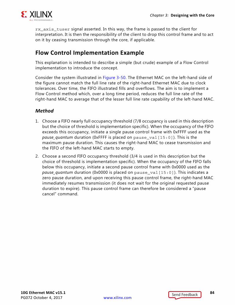
10G Ethernet MAC v15.1 84PG072 October 4, 2017 www.xilinx.com
Chapter 3: Designing with the Core
rx_axis_tuser signal asserted. In this way, the frame is passed to the client for interpretation. It is then the responsibility of the client to drop this control frame and to act on it by ceasing transmission through the core, if applicable.
Flow Control Implementation ExampleThis explanation is intended to describe a simple (but crude) example of a Flow Control implementation to introduce the concept.
Consider the system illustrated in Figure 3-50. The Ethernet MAC on the left-hand side of the figure cannot match the full line rate of the right-hand Ethernet MAC due to clock tolerances. Over time, the FIFO illustrated fills and overflows. The aim is to implement a Flow Control method which, over a long time period, reduces the full line rate of the right-hand MAC to average that of the lesser full line rate capability of the left-hand MAC.
Method
1. Choose a FIFO nearly full occupancy threshold (7/8 occupancy is used in this description but the choice of threshold is implementation specific). When the occupancy of the FIFO exceeds this occupancy, initiate a single pause control frame with 0xFFFF used as the pause_quantum duration (0xFFFF is placed on pause_val[15:0]). This is the maximum pause duration. This causes the right-hand MAC to cease transmission and the FIFO of the left-hand MAC starts to empty.
2. Choose a second FIFO occupancy threshold (3/4 is used in this description but the choice of threshold is implementation specific). When the occupancy of the FIFO falls below this occupancy, initiate a second pause control frame with 0x0000 used as the pause_quantum duration (0x0000 is placed on pause_val[15:0]). This indicates a zero pause duration, and upon receiving this pause control frame, the right-hand MAC immediately resumes transmission (it does not wait for the original requested pause duration to expire). This pause control frame can therefore be considered a “pause cancel” command.
Send Feedback
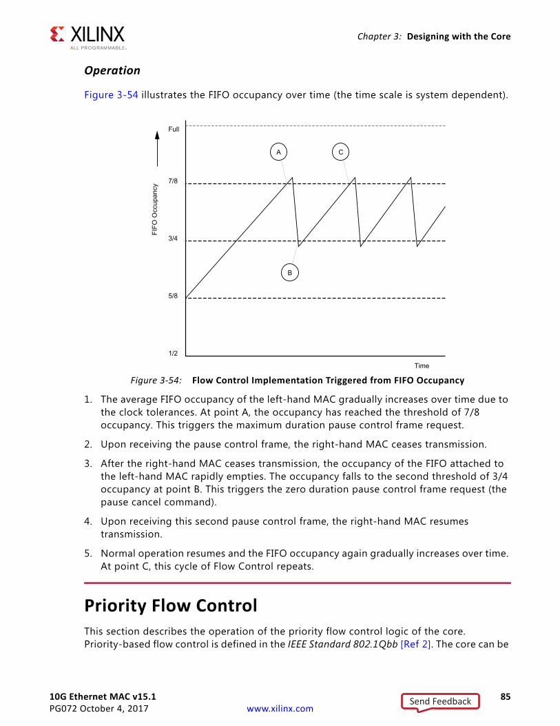
10G Ethernet MAC v15.1 85PG072 October 4, 2017 www.xilinx.com
Chapter 3: Designing with the Core
Operation
Figure 3-54 illustrates the FIFO occupancy over time (the time scale is system dependent).
1. The average FIFO occupancy of the left-hand MAC gradually increases over time due to the clock tolerances. At point A, the occupancy has reached the threshold of 7/8 occupancy. This triggers the maximum duration pause control frame request.
2. Upon receiving the pause control frame, the right-hand MAC ceases transmission.
3. After the right-hand MAC ceases transmission, the occupancy of the FIFO attached to the left-hand MAC rapidly empties. The occupancy falls to the second threshold of 3/4 occupancy at point B. This triggers the zero duration pause control frame request (the pause cancel command).
4. Upon receiving this second pause control frame, the right-hand MAC resumes transmission.
5. Normal operation resumes and the FIFO occupancy again gradually increases over time. At point C, this cycle of Flow Control repeats.
Priority Flow ControlThis section describes the operation of the priority flow control logic of the core. Priority-based flow control is defined in the IEEE Standard 802.1Qbb [Ref 2]. The core can be
X-Ref Target - Figure 3-54
Figure 3-54: Flow Control Implementation Triggered from FIFO Occupancy
Send Feedback
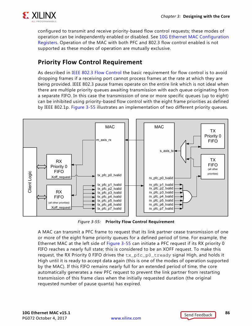
10G Ethernet MAC v15.1 86PG072 October 4, 2017 www.xilinx.com
Chapter 3: Designing with the Core
configured to transmit and receive priority-based flow control requests; these modes of operation can be independently enabled or disabled. See 10G Ethernet MAC Configuration Registers. Operation of the MAC with both PFC and 802.3 flow control enabled is not supported as these modes of operation are mutually exclusive.
Priority Flow Control RequirementAs described in IEEE 802.3 Flow Control the basic requirement for flow control is to avoid dropping frames if a receiving port cannot process frames at the rate at which they are being provided. IEEE 802.3 pause frames operate on the entire link which is not ideal when there are multiple priority queues awaiting transmission with each queue originating from a separate FIFO. In this case the transmission of one or more specific queues (up to eight) can be inhibited using priority-based flow control with the eight frame priorities as defined by IEEE 802.1p. Figure 3-55 illustrates an implementation of two different priority queues.
A MAC can transmit a PFC frame to request that its link partner cease transmission of one or more of the eight frame priority queues for a defined period of time. For example, the Ethernet MAC at the left side of Figure 3-55 can initiate a PFC request if its RX priority 0 FIFO reaches a nearly full state; this is considered to be an XOFF request. To make this request, the RX Priority 0 FIFO drives the tx_pfc_p0_tready signal High, and holds it High until it is ready to accept data again (this is one of the modes of operation supported by the MAC). If this FIFO remains nearly full for an extended period of time, the core automatically generates a new PFC request to prevent the link partner from restarting transmission of this frame class when the initially requested duration (the original requested number of pause quanta) has expired.
X-Ref Target - Figure 3-55
Figure 3-55: Priority Flow Control Requirement
Send Feedback
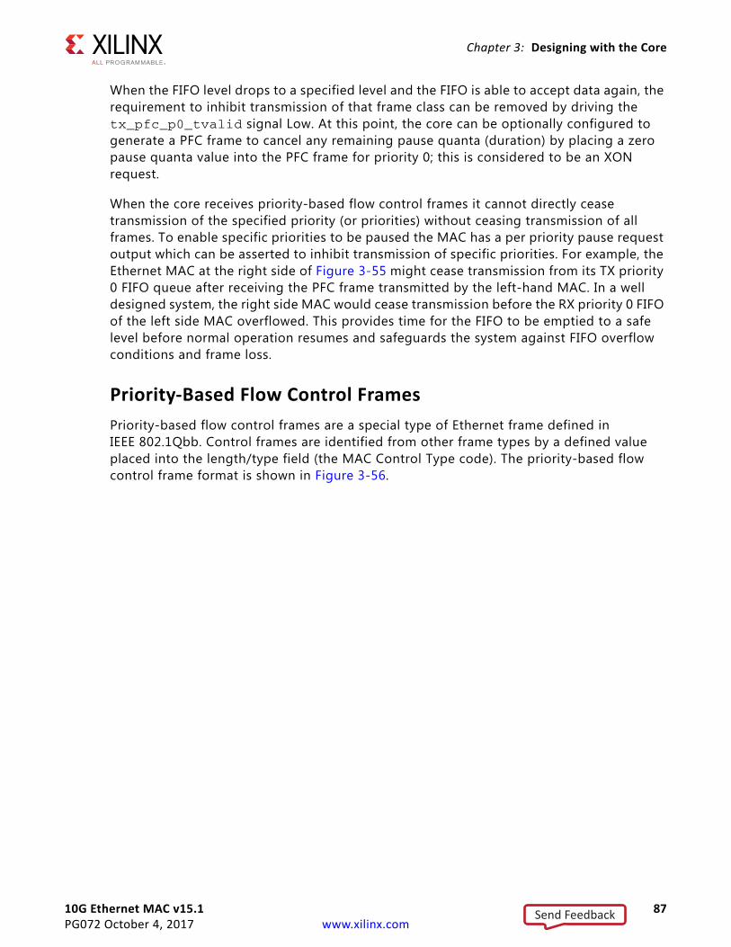
10G Ethernet MAC v15.1 87PG072 October 4, 2017 www.xilinx.com
Chapter 3: Designing with the Core
When the FIFO level drops to a specified level and the FIFO is able to accept data again, the requirement to inhibit transmission of that frame class can be removed by driving the tx_pfc_p0_tvalid signal Low. At this point, the core can be optionally configured to generate a PFC frame to cancel any remaining pause quanta (duration) by placing a zero pause quanta value into the PFC frame for priority 0; this is considered to be an XON request.
When the core receives priority-based flow control frames it cannot directly cease transmission of the specified priority (or priorities) without ceasing transmission of all frames. To enable specific priorities to be paused the MAC has a per priority pause request output which can be asserted to inhibit transmission of specific priorities. For example, the Ethernet MAC at the right side of Figure 3-55 might cease transmission from its TX priority 0 FIFO queue after receiving the PFC frame transmitted by the left-hand MAC. In a well designed system, the right side MAC would cease transmission before the RX priority 0 FIFO of the left side MAC overflowed. This provides time for the FIFO to be emptied to a safe level before normal operation resumes and safeguards the system against FIFO overflow conditions and frame loss.
Priority-Based Flow Control FramesPriority-based flow control frames are a special type of Ethernet frame defined in IEEE 802.1Qbb. Control frames are identified from other frame types by a defined value placed into the length/type field (the MAC Control Type code). The priority-based flow control frame format is shown in Figure 3-56.
Send Feedback
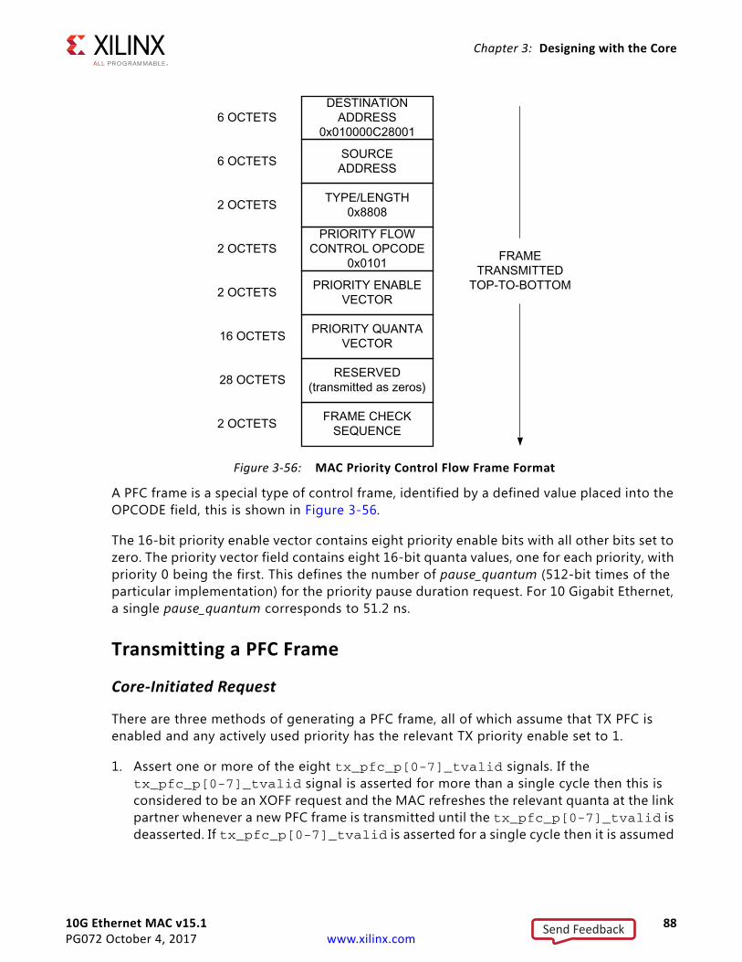
10G Ethernet MAC v15.1 88PG072 October 4, 2017 www.xilinx.com
Chapter 3: Designing with the Core
A PFC frame is a special type of control frame, identified by a defined value placed into the OPCODE field, this is shown in Figure 3-56.
The 16-bit priority enable vector contains eight priority enable bits with all other bits set to zero. The priority vector field contains eight 16-bit quanta values, one for each priority, with priority 0 being the first. This defines the number of pause_quantum (512-bit times of the particular implementation) for the priority pause duration request. For 10 Gigabit Ethernet, a single pause_quantum corresponds to 51.2 ns.
Transmitting a PFC Frame
Core-Initiated Request
There are three methods of generating a PFC frame, all of which assume that TX PFC is enabled and any actively used priority has the relevant TX priority enable set to 1.
1. Assert one or more of the eight tx_pfc_p[0-7]_tvalid signals. If the tx_pfc_p[0-7]_tvalid signal is asserted for more than a single cycle then this is considered to be an XOFF request and the MAC refreshes the relevant quanta at the link partner whenever a new PFC frame is transmitted until the tx_pfc_p[0-7]_tvalid is deasserted. If tx_pfc_p[0-7]_tvalid is asserted for a single cycle then it is assumed
X-Ref Target - Figure 3-56
Figure 3-56: MAC Priority Control Flow Frame Format
Send Feedback
10G Ethernet MAC v15.1 89PG072 October 4, 2017 www.xilinx.com
Chapter 3: Designing with the Core
that any required refresh is directly controlled by a subsequent reassertion of the respective tvalid as required.
2. Hold a tx_pfc_p[0-7]_tvalid signal High and the internal quanta count of the Ethernet MAC reaches the pre-programmed refresh value for that priority. On reaching this refresh value, the MAC “refreshes” the priority pause request by resending a new PFC frame with the pre-programmed pause value for the given priority. For each of the eight priorities, there is a configuration register that contains both the pause duration and the refresh value (see Table 2-28 in 10G Ethernet MAC Configuration Registers.)
3. Hold a tx_pfc_p[0-7]_tvalid High for more than one cycle; then deassert this signal and the TX auto XON feature is enabled. This results in a new PFC frame with the relevant priorities quanta being both enabled and forced to zero. This is considered to be an XON request for that priority.
When any new PFC frame is transmitted it also resends the quanta for any currently active, enabled priority, effectively refreshing each priority quanta at the link partner. This also restarts the internal quanta count.
The eight tx_pfc_p[0-7]_tvalid signals are synchronous with respect to tx_clk0. The various transmit methods can be seen in Figure 3-57. In Figure 3-57 the tx_pfc_p0_tvalid is asserted and held High. This results in a PFC frame with only the P0 quanta enabled (set to 0xFFFF). A number of cycles later tx_pfc_p2_tvalid is asserted for a single cycle and this results in a new PFC frame with both the P0 and P2 quantas enabled (and restarts the internal quanta count). The internal quanta count subsequently reaches the programmed refresh value for Priority 0 and a refresh PFC frame is sent with only the P0 quanta enabled (as all other tvalid requests are Low). tx_pfc_p6_tvalid is asserted and held High and this also results in a new PFC frame (P6 XOFF), with both P0 and P6 quantas enabled. Finally in Figure 3-57, tx_pfc_p0_tvalid is deasserted resulting in another PFC frame (P0 XON); this has both the P0 and P6 quantas enabled with the P0 quanta set to 0x0.
Send Feedback
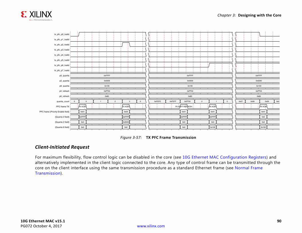
Chapter 3: Designing with the Core
10G Ethernet MAC v15.1 90PG072 October 4, 2017 www.xilinx.com
Client-Initiated Request
For maximum flexibility, flow control logic can be disabled in the core (see 10G Ethernet MAC Configuration Registers) and alternatively implemented in the client logic connected to the core. Any type of control frame can be transmitted through the core on the client interface using the same transmission procedure as a standard Ethernet frame (see Normal Frame Transmission).
X-Ref Target - Figure 3-57
Figure 3-57: TX PFC Frame Transmission
10G Ethernet MAC v15.1 91PG072 October 4, 2017 www.xilinx.com
Chapter 3: Designing with the Core
Receiving a PFC Frame
Core-Initiated Response to a PFC request
An error-free control frame is a received frame matching the format of Figure 3-56. It must pass all standard receiver frame checks (for example, FCS field checking); in addition, the control frame received must be exactly 64 bytes in length (from destination address through to the FCS field inclusive (this is the minimum legal Ethernet MAC frame size and the defined size for control frames) or the Control Frame Length Check Disable must be set.
Any control frame received that does not conform to these checks contains an error, and is passed to the receiver client with the rx_axis_tuser signal deasserted on the cycle that rx_axis_tlast is asserted.
PFC Frame Reception Disabled
When PFC reception is disabled (see 10G Ethernet MAC Configuration Registers), an error free control frame is received through the client interface with the rx_axis_tuser signal asserted. In this way, the frame is passed to the client logic for interpretation (see Client-Initiated Response to a Pause Request).
Pause Frame Reception Enabled
When pause control reception is enabled (see 10G Ethernet MAC Configuration Registers) and an error-free frame is received by the core, the frame decoding functions are performed:
• The destination address field is matched against the MAC control multicast address or the configured source address for the core (see 10G Ethernet MAC Configuration Registers).
• The length/type field is matched against the MAC Control type code, 88-08
• The opcode field contents are matched against the priority-based flow control opcode
If any of these checks are FALSE or the MAC receiver PFC is disabled, the frame is ignored by the PFC logic and passed up to the client.
If the frame passes all of these checks, is of minimum legal size, or the Control Frame Length Check Disable is set, and the MAC receiver PFC is enabled, then the priority enable field and per priority quanta values are extracted from the frame. If a particular priority is enabled in the frame with a non-zero pause quanta value, then the respective rx_pfc_p[0-7]_tvalid output is asserted and the requested quanta value loaded into the control logic for that priority. This control logic consists of a counter which is loaded with the requested pause quanta value, and decrements down to zero. The rx_pfc_p[0-7]_tvalid remains asserted while the local quanta counter is non zero. The local quanta counter does not start to decrement until rx_pfc_p[0-7]_tready is High.
Send Feedback
10G Ethernet MAC v15.1 92PG072 October 4, 2017 www.xilinx.com
Chapter 3: Designing with the Core
Subsequent deassertion of rx_pfc_p[0-7]_tready does not stop the quanta expiration. If the quanta counts down to zero and is not refreshed by reception of a new PFC frame with the respective priorities quanta enabled and non-zero then rx_pfc_p[0-7]_tvalid is deasserted. An example of this is shown in Figure 3-58 which shows the case where only one priority is active in a frame.
If at any time a new PFC frame is received with a priorities quanta enabled and set to zero then this is loaded into the local quanta count which results in the respective rx_pfc_p[0-7]_tvalid being deasserted immediately to re-enable transmission of this particular priority queue.
Because the received PFC frame has been acted on, it is passed to the client with rx_axis_tuser deasserted to indicate that it should be dropped. The frame is still marked good in the statistics vector and counters.
Note: Any frame in which the length/type field contains the MAC Control Type should be dropped by the receiver client logic. All control frames are indicated by rx_statistics_vector bit 20 (see Receive Statistics Vector).
Client-Initiated Response to a Pause RequestFor maximum flexibility, flow control logic can be disabled in the core (see 10G Ethernet MAC Configuration Registers) and alternatively implemented in the client logic connected to the core. Any type of error free control frame is then passed through the core with the rx_axis_tuser signal asserted. In this way, the frame is passed to the client for interpretation. It is then the responsibility of the client to drop this control frame and to act on it by ceasing transmission of the appropriate priorities through the core, if applicable.
PFC Implementation ExampleThis section describes a simple example of a PFC implementation.
In Figure 3-55 the client logic connected to the Ethernet MAC on the left side is unable to service the data in the RX priority 0 FIFO for an extended period of time. Over time, the RX priority 0 FIFO illustrated fills and overflows. The aim is to implement a PFC method which applies back pressure on only the priority 0 traffic to ensure no frames are dropped while allowing the other priority queues to continue.
X-Ref Target - Figure 3-58
Figure 3-58: RX PFC Frame Reception
Send Feedback
10G Ethernet MAC v15.1 93PG072 October 4, 2017 www.xilinx.com
Chapter 3: Designing with the Core
Method
1. Choose an RX priority 0 FIFO nearly-full occupancy threshold (7/8 occupancy is used in this example). When the FIFO exceeds this occupancy, assert the XOFF request signal to initiate a PFC frame with priority 0 enabled and 0xFFFF used as the priority 0 pause_quantum duration (0xFFFF is the default value of the priority 0 quanta register). This is the maximum pause duration. This causes the left-hand MAC to transmit a PFC frame, which in turn causes the right-hand MAC to assert its rx_pfc_p0_tvalid to request that the TX priority 0 FIFO on the right-hand side stops transmission. If the client logic of the left-hand MAC continues to be unable to service the RX priority 0 FIFO then the left-hand Ethernet MAC automatically re-sends the PFC frame each time 0xFF00 quanta has expired (this is the default value of the priority 0 refresh), that is, before the previously sent quanta has expired.
2. Choose a second RX priority 0 FIFO occupancy threshold (3/4 is used in this example). When the occupancy of the FIFO falls below this occupancy, send an XON request by deasserting the tx_pfc_p0_tvalid signal. If the TX auto XON feature is enabled this initiates a PFC frame with priority 0 enabled and the priority 0 quanta set to 0x0000. This indicates a zero pause duration (XON), and upon receiving this PFC frame, the right-hand MAC deasserts the rx_pfc_p0_tvalid allowing the TX priority 0 FIFO on the right to resume transmission (it does not wait for the original requested quantum duration to expire). If the TX auto XON feature is not enabled then no PFC frame is sent and transmission does not restart until the requested quantum duration has expired.
Send Feedback
10G Ethernet MAC v15.1 94PG072 October 4, 2017 www.xilinx.com
Chapter 3: Designing with the Core
Operation
Figure 3-59 shows the Priority 0 FIFO occupancy over time (the time scale is system dependent).
1. The FIFO occupancy is maintained at a low level as the client logic is able to service the frames. At point A, the client logic is unable to service the FIFO and the occupancy increases. At point B the FIFO has reached the threshold of 7/8 occupancy. This triggers the XOFF request assertion and a PFC frame is generated and requested priority 0 traffic is stopped.
2. Upon receiving the PFC frame, the right-hand priority 0 FIFO ceases transmission.
3. The client logic remains unable to service the priority 0 FIFO for an extended duration and subsequent PFC frames are automatically generated at C to ensure the Priority 0 FIFO on the right does not restart.
4. The client begins to service the priority 0 FIFO at point D and the FIFO empties. The occupancy falls to the second threshold of ¾ occupancy at point E. This triggers the XON PFC frame request.
5. Upon receiving this PFC frame, the right-hand MAC deasserts rx_pfc_p0_tvalid and the priority 0 FIFO resumes transmission.
6. Normal operation resumes.
X-Ref Target - Figure 3-59
Figure 3-59: Priority Flow Control Implementation Triggered from FIFO Occupancy
Send Feedback
10G Ethernet MAC v15.1 95PG072 October 4, 2017 www.xilinx.com
Chapter 3: Designing with the Core
Special Design ConsiderationsThis section describes considerations that can apply in particular design cases.
Multiple Core InstancesIn a large design, it might be necessary or desirable to have more than one instance of the 10G Ethernet MAC core on a single FPGA. One possible clock scheme for two 64-bit datapath instances, both with an XGMII interface is shown in Figure 3-60.
The transmit clock tx_clk0 can be shared among multiple core instances as illustrated, resulting in a common transmitter clock domain across the device.
A common receiver clock domain is not possible; each core derives an independent receiver clock from its XGMII interface as shown.
Although not illustrated, if the optional Management Interface is used, s_axi_aclk can also be shared between cores. The s_axi_aclk signal consumes another BUFG global clock buffer resource.
Send Feedback
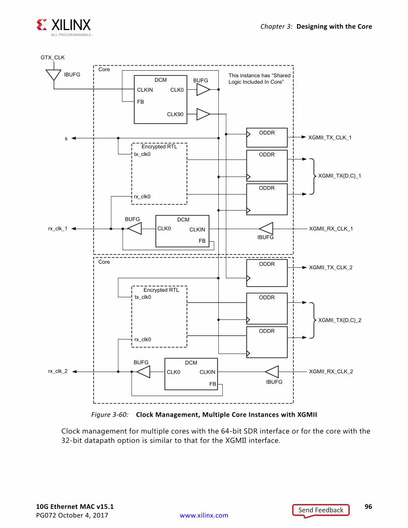
10G Ethernet MAC v15.1 96PG072 October 4, 2017 www.xilinx.com
Chapter 3: Designing with the Core
X-Ref Target - Figure 3-60
Clock management for multiple cores with the 64-bit SDR interface or for the core with the 32-bit datapath option is similar to that for the XGMII interface.
Figure 3-60: Clock Management, Multiple Core Instances with XGMII
Send Feedback
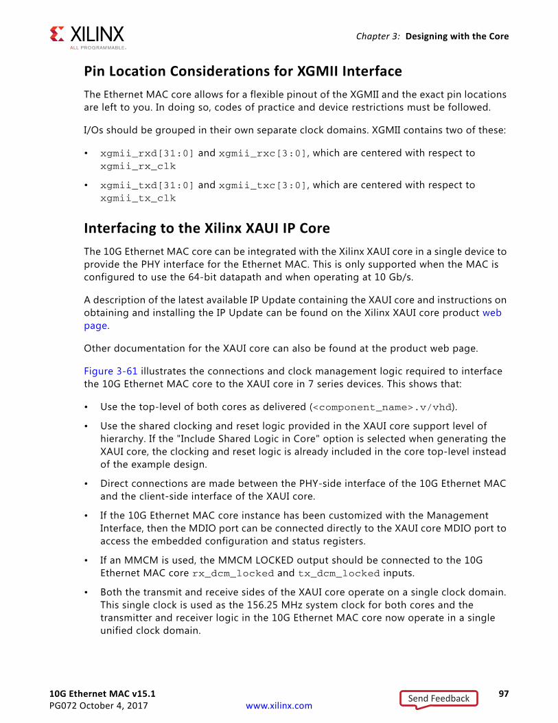
10G Ethernet MAC v15.1 97PG072 October 4, 2017 www.xilinx.com
Chapter 3: Designing with the Core
Pin Location Considerations for XGMII InterfaceThe Ethernet MAC core allows for a flexible pinout of the XGMII and the exact pin locations are left to you. In doing so, codes of practice and device restrictions must be followed.
I/Os should be grouped in their own separate clock domains. XGMII contains two of these:
• xgmii_rxd[31:0] and xgmii_rxc[3:0], which are centered with respect to xgmii_rx_clk
• xgmii_txd[31:0] and xgmii_txc[3:0], which are centered with respect to xgmii_tx_clk
Interfacing to the Xilinx XAUI IP CoreThe 10G Ethernet MAC core can be integrated with the Xilinx XAUI core in a single device to provide the PHY interface for the Ethernet MAC. This is only supported when the MAC is configured to use the 64-bit datapath and when operating at 10 Gb/s.
A description of the latest available IP Update containing the XAUI core and instructions on obtaining and installing the IP Update can be found on the Xilinx XAUI core product web page.
Other documentation for the XAUI core can also be found at the product web page.
Figure 3-61 illustrates the connections and clock management logic required to interface the 10G Ethernet MAC core to the XAUI core in 7 series devices. This shows that:
• Use the top-level of both cores as delivered (<component_name>.v/vhd).
• Use the shared clocking and reset logic provided in the XAUI core support level of hierarchy. If the "Include Shared Logic in Core" option is selected when generating the XAUI core, the clocking and reset logic is already included in the core top-level instead of the example design.
• Direct connections are made between the PHY-side interface of the 10G Ethernet MAC and the client-side interface of the XAUI core.
• If the 10G Ethernet MAC core instance has been customized with the Management Interface, then the MDIO port can be connected directly to the XAUI core MDIO port to access the embedded configuration and status registers.
• If an MMCM is used, the MMCM LOCKED output should be connected to the 10G Ethernet MAC core rx_dcm_locked and tx_dcm_locked inputs.
• Both the transmit and receive sides of the XAUI core operate on a single clock domain. This single clock is used as the 156.25 MHz system clock for both cores and the transmitter and receiver logic in the 10G Ethernet MAC core now operate in a single unified clock domain.
Send Feedback
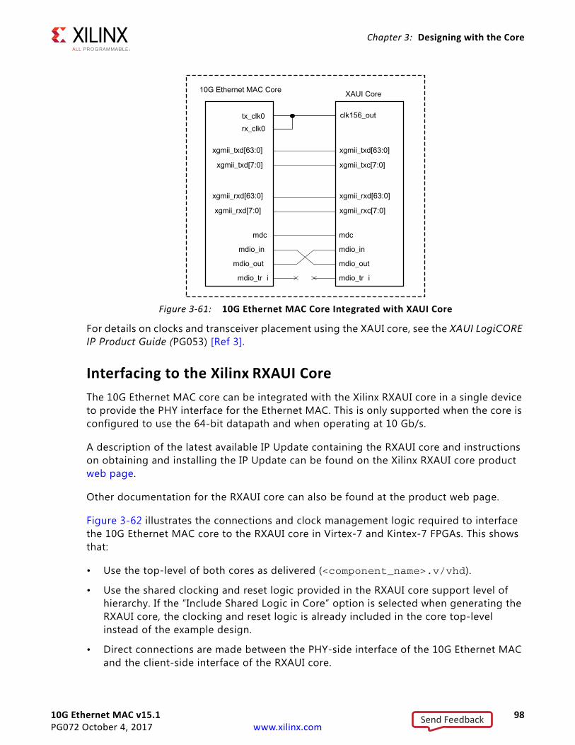
10G Ethernet MAC v15.1 98PG072 October 4, 2017 www.xilinx.com
Chapter 3: Designing with the Core
For details on clocks and transceiver placement using the XAUI core, see the XAUI LogiCORE IP Product Guide (PG053) [Ref 3].
Interfacing to the Xilinx RXAUI CoreThe 10G Ethernet MAC core can be integrated with the Xilinx RXAUI core in a single device to provide the PHY interface for the Ethernet MAC. This is only supported when the core is configured to use the 64-bit datapath and when operating at 10 Gb/s.
A description of the latest available IP Update containing the RXAUI core and instructions on obtaining and installing the IP Update can be found on the Xilinx RXAUI core product web page.
Other documentation for the RXAUI core can also be found at the product web page.
Figure 3-62 illustrates the connections and clock management logic required to interface the 10G Ethernet MAC core to the RXAUI core in Virtex-7 and Kintex-7 FPGAs. This shows that:
• Use the top-level of both cores as delivered (<component_name>.v/vhd).
• Use the shared clocking and reset logic provided in the RXAUI core support level of hierarchy. If the “Include Shared Logic in Core” option is selected when generating the RXAUI core, the clocking and reset logic is already included in the core top-level instead of the example design.
• Direct connections are made between the PHY-side interface of the 10G Ethernet MAC and the client-side interface of the RXAUI core.
X-Ref Target - Figure 3-61
Figure 3-61: 10G Ethernet MAC Core Integrated with XAUI Core
Send Feedback
10G Ethernet MAC v15.1 99PG072 October 4, 2017 www.xilinx.com
Chapter 3: Designing with the Core
• If the 10G Ethernet MAC core instance has been customized with the Management Interface, then the MDIO port can be connected directly to the RXAUI core MDIO port to access the embedded configuration and status registers.
• If an MMCM is used, the MMCM LOCKED output should be connected to the 10G Ethernet MAC core rx_dcm_locked and tx_dcm_locked inputs.
• Both the transmit and receive client interfaces of the RXAUI core operate on a single clock domain. This single clock is used as the 156.25 MHz system clock for both cores and the transmitter and receiver logic in the 10G Ethernet MAC core now operate in a single unified clock domain.
For details on clocks and transceiver placement using the RXAUI core, see the RXAUI LogiCORE IP Product Guide (PG083) [Ref 4].
Interfacing to the Xilinx 10G Ethernet PCS/PMA CoreThe 10G Ethernet MAC core can be integrated with the Xilinx 10G Ethernet PCS/PMA core in a single device to provide the PHY interface for the Ethernet MAC. At 10 Gb/s this is supported with both the 64-bit datapath or the 32-bit datapath but the PCS/PMA must be configured to use the same datapath width.
A description of the latest available IP update containing the 10G Ethernet PCS/PMA core and instructions on obtaining and installing the IP update can be found on the Xilinx 10G Ethernet PCS/PMA product web page.
Other documentation for the PCS/PMA core can also be found at the product web page.
X-Ref Target - Figure 3-62
Figure 3-62: 10G Ethernet MAC Core Integrated with RXAUI Core
Send Feedback
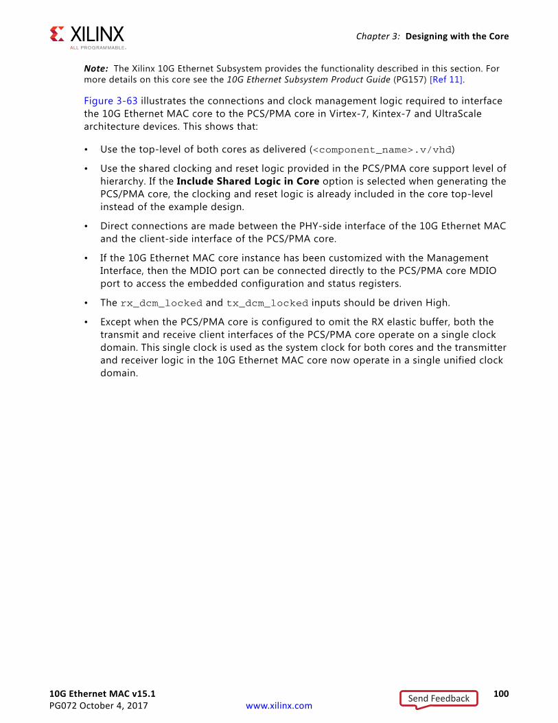
10G Ethernet MAC v15.1 100PG072 October 4, 2017 www.xilinx.com
Chapter 3: Designing with the Core
Note: The Xilinx 10G Ethernet Subsystem provides the functionality described in this section. For more details on this core see the 10G Ethernet Subsystem Product Guide (PG157) [Ref 11].
Figure 3-63 illustrates the connections and clock management logic required to interface the 10G Ethernet MAC core to the PCS/PMA core in Virtex-7, Kintex-7 and UltraScale architecture devices. This shows that:
• Use the top-level of both cores as delivered (<component_name>.v/vhd)
• Use the shared clocking and reset logic provided in the PCS/PMA core support level of hierarchy. If the Include Shared Logic in Core option is selected when generating the PCS/PMA core, the clocking and reset logic is already included in the core top-level instead of the example design.
• Direct connections are made between the PHY-side interface of the 10G Ethernet MAC and the client-side interface of the PCS/PMA core.
• If the 10G Ethernet MAC core instance has been customized with the Management Interface, then the MDIO port can be connected directly to the PCS/PMA core MDIO port to access the embedded configuration and status registers.
• The rx_dcm_locked and tx_dcm_locked inputs should be driven High.
• Except when the PCS/PMA core is configured to omit the RX elastic buffer, both the transmit and receive client interfaces of the PCS/PMA core operate on a single clock domain. This single clock is used as the system clock for both cores and the transmitter and receiver logic in the 10G Ethernet MAC core now operate in a single unified clock domain.
Send Feedback
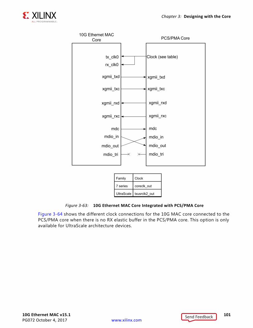
10G Ethernet MAC v15.1 101PG072 October 4, 2017 www.xilinx.com
Chapter 3: Designing with the Core
Figure 3-64 shows the different clock connections for the 10G MAC core connected to the PCS/PMA core when there is no RX elastic buffer in the PCS/PMA core. This option is only available for UltraScale architecture devices.
X-Ref Target - Figure 3-63
Figure 3-63: 10G Ethernet MAC Core Integrated with PCS/PMA Core
PCS/PMA Core
tx_clk0
rx_clk0
xgmii_txd
xgmii_txc
xgmii_rxd
xgmii_rxc
mdc
mdio_in
mdio_out
mdio_tri
xgmii_txd
xgmii_txc
xgmii_rxd
xgmii_rxc
mdc
mdio_in
mdio_out
mdio_tri
Clock (see table)
Family
7 series
UltraScale
Clock
coreclk_out
txusrclk2_out
10G Ethernet MAC Core
Send Feedback
10G Ethernet MAC v15.1 102PG072 October 4, 2017 www.xilinx.com
Chapter 3: Designing with the Core
For details on clocks and transceiver placement using the PCS/PMA core, see the 10G Ethernet PCS/PMA LogiCORE IP Product Guide (PG068) [Ref 5].
Evaluation Core in Hardware ImplementationWhen the core is generated with a Full System Hardware Evaluation, the core can be tested in the target device for several hours before ceasing to function.
Symptoms of the hardware evaluation timeout include:
• The transmitter failing to assert tx_axis_tready in response to tx_axis_tvalid.
• The receiver failing to recognize frames in the inbound data stream.
• After the timeout occurs, the core can be reactivated by reconfiguring the FPGA.
X-Ref Target - Figure 3-64
Figure 3-64: 10G Ethernet MAC Core with PCS/PMA Core with No RX Elastic Buffer
PCS/PMA Core10G Ethernet MAC Core
tx_clk0
rx_clk0
xgmii_txd
xgmii_txc
xgmii_rxd
xgmii_rxc
mdc
mdio_in
mdio_out
mdio_tri
xgmii_txd
xgmii_txc
xgmii_rxd
xgmii_rxc
mdc
mdio_in
mdio_out
mdio_tri
txusrclk2_out
rxrecclk_out
Send Feedback
10G Ethernet MAC v15.1 103PG072 October 4, 2017 www.xilinx.com
Chapter 4
Design Flow StepsThis chapter describes customizing and generating the core, constraining the core, and the simulation, synthesis and implementation steps that are specific to this IP core. More detailed information about the standard Vivado® design flows and the IP integrator can be found in the following Vivado Design Suite user guides:
• Vivado Design Suite User Guide: Designing IP Subsystems using IP Integrator (UG994) [Ref 6]
• Vivado Design Suite User Guide: Designing with IP (UG896) [Ref 7]
• Vivado Design Suite User Guide: Getting Started (UG910) [Ref 8]
• Vivado Design Suite User Guide: Logic Simulation (UG900) [Ref 9]]
Customizing and Generating the CoreThis section includes information about using Xilinx tools to customize and generate the core in the Vivado® Design Suite.
If you are customizing and generating the core in the Vivado IP integrator, see the Vivado Design Suite User Guide: Designing IP Subsystems using IP Integrator (UG994) [Ref 6] for detailed information. IP integrator might auto-compute certain configuration values when validating or generating the design. To check whether the values do change, see the description of the parameter in this chapter. To view the parameter value you can run the validate_bd_design command in the Tcl Console.
You can customize the IP for use in your design by specifying values for the various parameters associated with the IP core using the following steps:
1. Select the IP from the IP catalog.
2. Double-click the selected IP or select the Customize IP command from the toolbar or right-click menu.
For details, see the Vivado Design Suite User Guide, Designing with IP (UG896) [Ref 7] and the Vivado Design Suite User Guide, Getting Started (UG910) [Ref 8].
Note: Figures in this chapter are illustrations of the Vivado IDE. The layout depicted here might vary from the current version.
Send Feedback
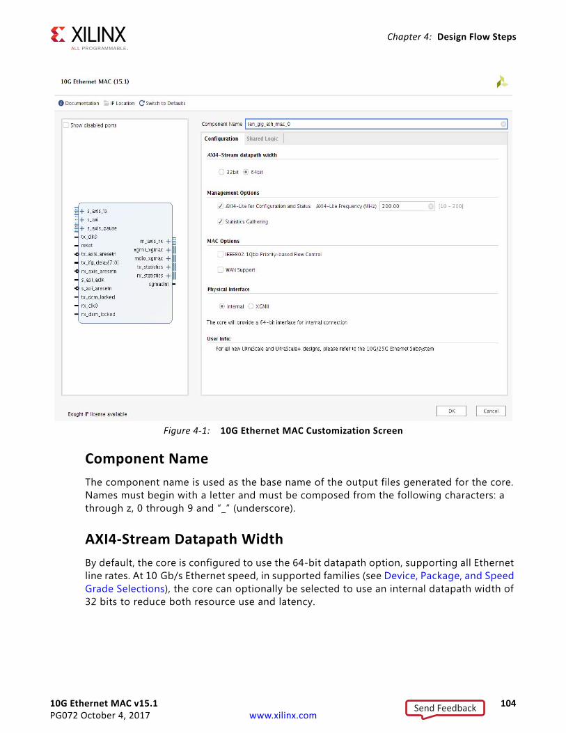
10G Ethernet MAC v15.1 104PG072 October 4, 2017 www.xilinx.com
Chapter 4: Design Flow Steps
Component NameThe component name is used as the base name of the output files generated for the core. Names must begin with a letter and must be composed from the following characters: a through z, 0 through 9 and “_” (underscore).
AXI4-Stream Datapath WidthBy default, the core is configured to use the 64-bit datapath option, supporting all Ethernet line rates. At 10 Gb/s Ethernet speed, in supported families (see Device, Package, and Speed Grade Selections), the core can optionally be selected to use an internal datapath width of 32 bits to reduce both resource use and latency.
X-Ref Target - Figure 4-1
Figure 4-1: 10G Ethernet MAC Customization Screen
Send Feedback
10G Ethernet MAC v15.1 105PG072 October 4, 2017 www.xilinx.com
Chapter 4: Design Flow Steps
Statistics GatheringThis checkbox selects whether the statistics counters are included in the generated core. This option is only available if the Management Interface option is selected. The default is to have statistics counters included.
AXI4-Lite for Configuration and StatusSelect this option to include the AXI4-Lite interface in the generated core. Deselect this option to remove the AXI4-Lite interface and expose a simple bit vector to manage the core. The default is to have the AXI4-Lite interface included.
AXI4-Lite FrequencyWhen the AXI4-Lite interface is selected this allows the default frequency of the AXI4-Lite interface to be specified. This is used to provide a target frequency for the AXI4-Lite logic during out of context synthesis. When the core is instantiated in a system the system clock frequency is used for timing analysis.
WAN SupportSelect this option to include WAN mode support in the core. When included, circuitry to perform Interframe Gap Adjustment is included in the core. This option is only supported at 10 Gb/s when using the 64-bit datapath option.
Physical InterfaceThe physical interface section has a choice of two selections; XGMII, which implements the 32-bit DDR interface to the physical layer, and Internal, which selects the internal 64-bit/32-bit SDR interface to the physical layer. Only the internal interface is supported at 10 Gb/s when using the 32-bit datapath option.
IEEE802.1Qbb Priority-Based Flow ControlSelect this option to include Priority Flow control support in the core. When included, circuitry to generate PFC frames on transmit and interpret PFC frame on receive is included as well as enhanced XON/XOFF support for IEEE 802.3 pause requests. The default is for this to be disabled.
Shared LogicSelect whether some shared logic (including transmit MMCMs, BUFGs) is included in the core itself or in the example design (see Shared Logic in Chapter 3).
Send Feedback
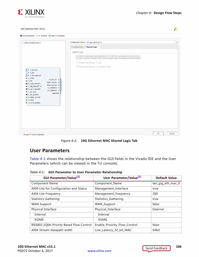
10G Ethernet MAC v15.1 106PG072 October 4, 2017 www.xilinx.com
Chapter 4: Design Flow Steps
User ParametersTable 4-1 shows the relationship between the GUI fields in the Vivado IDE and the User Parameters (which can be viewed in the Tcl console).
X-Ref Target - Figure 4-2
Figure 4-2: 10G Ethernet MAC Shared Logic Tab
Table 4-1: GUI Parameter to User Parameter RelationshipGUI Parameter/Value(1) User Parameter/Value(1) Default Value
Component Name Component_Name ten_gig_eth_mac_0
AXI4-Lite for Configuration and Status Management_Interface true
AXI4-Lite Frequency Management_Frequency 200
Statistics Gathering Statistics_Gathering true
WAN Support WAN_Support false
Physical Interface Physical_Interface Internal
Internal Internal
XGMII XGMII
IEEE802.1Qbb Priority Based Flow Control Enable_Prioirity_Flow_Control false
AXI4-Stream datapath width Low_Latency_32_bit_MAC 64bit
Send Feedback
10G Ethernet MAC v15.1 107PG072 October 4, 2017 www.xilinx.com
Chapter 4: Design Flow Steps
Output GenerationFor details, see the Vivado Design Suite User Guide, Designing with IP (UG896) [Ref 7].
Constraining the CoreThis section contains information about constraining the core in the Vivado Design Suite.
Required ConstraintsThis section defines the constraint requirements of the 10G Ethernet MAC core. An example XDC is provided with the HDL example design to provide the board-level constraints. This is specific to the example design and is only expected to be used as a template for the user design. See Chapter 5, Example Design. This XDC file, named <component name>_example_design.xdc, is found in the IP Sources tab of the Sources window in the Examples file group.
Also, core-level constraints files (<component_name>.xdc and <component_name>_clocks.xdc) are found in the IP Sources tab. These are applied to the core on a per-instance basis and cover all internal constraints.
Device, Package, and Speed Grade SelectionsThe core can be implemented in 7 series or UltraScale devices with these attributes:
• Large enough to accommodate the core
• Contains a sufficient number of IOBs
• Device has a supported speed grade (see Table 4-2).
32 bit 32bit
64 bit 64bit
Notes: 1. Parameter values are listed in the table where the GUI parameter value differs from the user parameter value. Such
values are shown in this table as indented below the associated parameter.
Table 4-2: Supported Speed Grades
Device Family Speed Grade (64-bit datapath)(1)
Speed Grade (32-bit datapath)
Virtex-7 FPGA –1 or faster –1 or faster
Kintex-7 FPGA –1 or faster –2 or faster
Table 4-1: GUI Parameter to User Parameter Relationship (Cont’d)
GUI Parameter/Value(1) User Parameter/Value(1) Default Value
Send Feedback
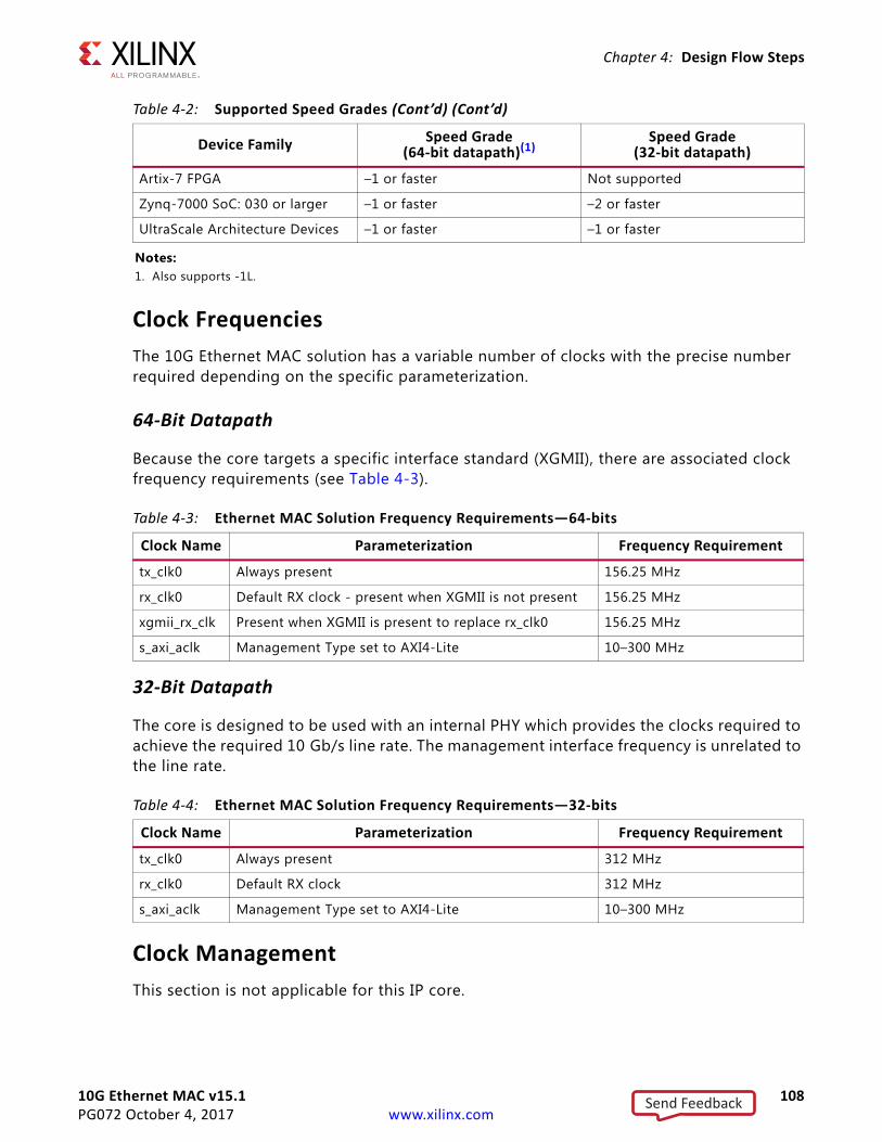
10G Ethernet MAC v15.1 108PG072 October 4, 2017 www.xilinx.com
Chapter 4: Design Flow Steps
Clock FrequenciesThe 10G Ethernet MAC solution has a variable number of clocks with the precise number required depending on the specific parameterization.
64-Bit Datapath
Because the core targets a specific interface standard (XGMII), there are associated clock frequency requirements (see Table 4-3).
32-Bit Datapath
The core is designed to be used with an internal PHY which provides the clocks required to achieve the required 10 Gb/s line rate. The management interface frequency is unrelated to the line rate.
Clock ManagementThis section is not applicable for this IP core.
Artix-7 FPGA –1 or faster Not supported
Zynq-7000 SoC: 030 or larger –1 or faster –2 or faster
UltraScale Architecture Devices –1 or faster –1 or faster
Notes: 1. Also supports -1L.
Table 4-3: Ethernet MAC Solution Frequency Requirements—64-bits
Clock Name Parameterization Frequency Requirement
tx_clk0 Always present 156.25 MHz
rx_clk0 Default RX clock - present when XGMII is not present 156.25 MHz
xgmii_rx_clk Present when XGMII is present to replace rx_clk0 156.25 MHz
s_axi_aclk Management Type set to AXI4-Lite 10–300 MHz
Table 4-4: Ethernet MAC Solution Frequency Requirements—32-bits
Clock Name Parameterization Frequency Requirement
tx_clk0 Always present 312 MHz
rx_clk0 Default RX clock 312 MHz
s_axi_aclk Management Type set to AXI4-Lite 10–300 MHz
Table 4-2: Supported Speed Grades (Cont’d) (Cont’d)
Device Family Speed Grade (64-bit datapath)(1)
Speed Grade (32-bit datapath)
Send Feedback
10G Ethernet MAC v15.1 109PG072 October 4, 2017 www.xilinx.com
Chapter 4: Design Flow Steps
Clock PlacementThis section is not applicable for this IP core.
BankingThis section is not applicable for this IP core.
Transceiver PlacementThis section is not applicable for this IP core.
I/O Standard and PlacementThis section is not applicable for this IP core.
SimulationFor comprehensive information about Vivado simulation components, as well as information about using supported third party tools, see the Vivado Design Suite User Guide, Logic Simulation (UG900) [Ref 9].
IMPORTANT: For cores targeting 7 series or Zynq®-7000 devices, UNIFAST libraries are not supported. Xilinx IP is tested and qualified with UNISIM libraries only.
Synthesis and ImplementationFor details about synthesis and implementation, see the Vivado Design Suite User Guide, Designing with IP (UG896) [Ref 7].
Send Feedback
10G Ethernet MAC v15.1 110PG072 October 4, 2017 www.xilinx.com
Chapter 5
Example DesignThis chapter contains information about the example design provided in the Vivado® Design Suite, including a description of the file groups, the contents of the example HDL wrappers, and the operation of the demonstration test bench.
To generate the Example Design for the 10G Ethernet MAC core:
• In the Vivado Design Suite: Right click on the core and select Open IP Example Design
• From the TCL command line:
open_example_project -force -dir <directory_to_put_project> [get_ips <IP_Name>]
The example design includes a basic state machine which, through the AXI4-Lite interface, brings up the MAC to allow basic frame transfer. A simple Frame Generator and Frame Checker are also included which can be used to transmit fixed pattern data which can be looped back, with any received data optionally being checked.
Two modes of operation are provided:
• Frames generated by the generator module are inserted into the TX FIFO.
• FIFO side loopback where frames from the RX FIFO are inserted into TX FIFO.
Basic control of the state machine, allowing configuration changes in the subsystem, is achieved using simple input control signals. These are designed so that they could potentially be connected to push buttons or DIP switches if the design is targeted to a suitable board.
Send Feedback
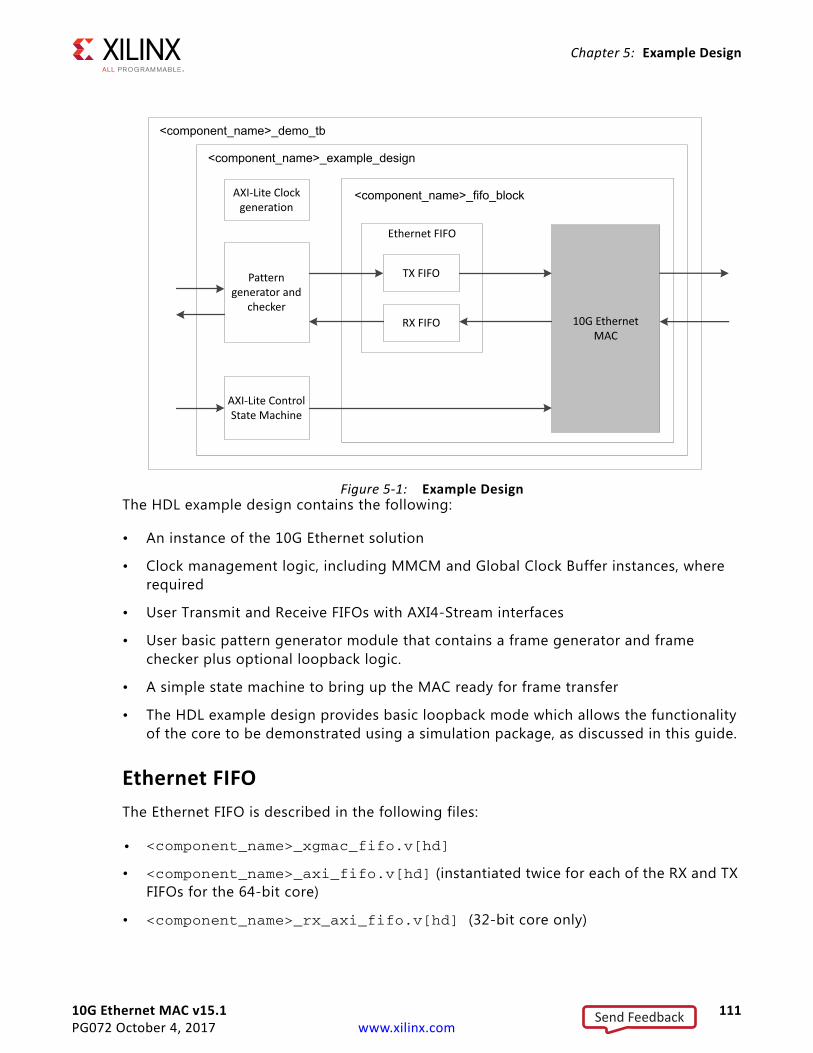
10G Ethernet MAC v15.1 111PG072 October 4, 2017 www.xilinx.com
Chapter 5: Example Design
The HDL example design contains the following:
• An instance of the 10G Ethernet solution
• Clock management logic, including MMCM and Global Clock Buffer instances, where required
• User Transmit and Receive FIFOs with AXI4-Stream interfaces
• User basic pattern generator module that contains a frame generator and frame checker plus optional loopback logic.
• A simple state machine to bring up the MAC ready for frame transfer
• The HDL example design provides basic loopback mode which allows the functionality of the core to be demonstrated using a simulation package, as discussed in this guide.
Ethernet FIFOThe Ethernet FIFO is described in the following files:
• <component_name>_xgmac_fifo.v[hd]
• <component_name>_axi_fifo.v[hd] (instantiated twice for each of the RX and TX FIFOs for the 64-bit core)
• <component_name>_rx_axi_fifo.v[hd] (32-bit core only)
X-Ref Target - Figure 5-1
Figure 5-1: Example Design
10G EthernetMAC
<component_name>_fifo_block
<component_name>_example_design
Pattern generator and
checker
Pattern generator and
checker
AXI-Lite ControlState Machine
AXI-Lite Control State Machine
TX FIFOTX FIFO
RX FIFORX FIFO
Ethernet FIFOEthernet FIFO
<component_name>_demo_tb
AXI-Lite Clockgeneration
AXI-Lite Clock generation
Send Feedback
10G Ethernet MAC v15.1 112PG072 October 4, 2017 www.xilinx.com
Chapter 5: Example Design
• <component_name>_tx_axi_fifo.v[hd] (32-bit core only)
The Ethernet FIFO contains an instance of a tx_client_fifo to connect to the core TX AXI4-Stream interface, and an instance of the rx_client_fifo to connect to the core RX AXI4-Stream interface. Both transmit and receive FIFO components implement an AXI4-Stream user interface, through which the frame data can be transmitted and received.
For the 32-bit core the FIFOs translate from the 32-bit data width used by the core to a 64-bit width user interface.
RX FIFO
The rx_client_fifo is built around a Dual Port Inferred RAM, giving a total memory capacity of up to 131,072 bytes. The memory capacity is set by a local parameter FIFO_SIZE. The FIFO capacity is specified in terms of number of 8-byte words using this parameter. The default value for FIFO_SIZE is set to 1024 which translates to a FIFO capacity of 1024 x 8 = 8192 bytes. The receive FIFO receives frame data from the subsystem. If the frame is not errored, that frame is presented on the AXI4-Stream FIFO interface for reading (in this case by the Frame Checker module). If the frame is errored, that frame is dropped by the receive FIFO.
If the receive FIFO memory overflows, the frame currently being received is dropped, regardless of whether it is a good or bad frame. The 4-bit status signal, fifo_status, can be used to monitor FIFO occupancy. Situations in which the memory can overflow are:
• The FIFO size set by FIFO_SIZE parameter limits the size of the frames that it can store without error. If a frame is larger than the FIFO capacity as specified by the FIFO_SIZE parameter, the FIFO can overflow and data is then lost. It is therefore recommended that the example design is not used with the MAC solution in jumbo frame mode for frames of larger than the FIFO capacity as specified by the FIFO_SIZE parameter.
• The FIFO will eventually overflow if data is being written into it faster than data is being read out. For example, if the loopback path is set from the RX FIFO to the TX FIFO, then overflow occurs if the receiver clock is running at a faster rate than the transmitter clock or if the inter-packet gap between the received frames is smaller than the inter-packet gap between the transmitted frames. If this is the case, the TX FIFO is not able to read data from the RX FIFO as fast as it is being received.
TX FIFO
The tx_client_fifo is built around a Dual Port Inferred RAM, giving a total memory capacity of up to 131,072 bytes. The memory capacity is set by a local parameter FIFO_SIZE. FIFO capacity is specified in terms of number of 8-byte words using this parameter. The default value for FIFO_SIZE is set to 1024 which translates to a FIFO capacity of 1024 x 8 = 8192 bytes. When a full frame has been written into the transmit FIFO, the FIFO presents data to the MAC transmitter. The MAC uses tx_axis_mac_tready to throttle the data until it has control of the medium. If the FIFO memory fills up, the tx_axis_fifo_tready
Send Feedback
10G Ethernet MAC v15.1 113PG072 October 4, 2017 www.xilinx.com
Chapter 5: Example Design
signal is used to halt the AXI4-Stream interface writing in data, until space becomes available in the FIFO. If the FIFO memory fills up but no full frames are available for transmission. For example, if a frame is larger than the FIFO capacity as specified by the FIFO_SIZE parameter, the FIFO asserts the fifo_full signal and continues to accept the rest of the frame from connected logic; In such cases the FIFO write pointer wraps-around and the existing frame data in the FIFO is overwritten. The frame integrity is no longer guaranteed and the corrupted frame is eventually transmitted out. This ensures that the AXI4-Stream FIFO interface does not lock up.
CAUTION! Ensure that the length of the frame being presented at the TX FIFO AXI4-Stream interface does not exceed the FIFO capacity. Frames whose length exceed the FIFO capacity will result in corrupted frame being sent out.
Basic Pattern Generator ModuleThe basic pattern generator is described in the following files:
• <component_name>_gen_check_wrapper.v[hd]
• <component_name>_axi_pat_gen.v[hd]
• <component_name>_axi_pat_check.v[hd]
• <component_name>_axi_mux.v[hd]
• <component_name>_address_swap.v[hd]
The gen_check_wrapper has two main functional modes: generator and loopback, configured by the enable_pat_gen signal input of the example design. In loopback, the data from the RX FIFO is passed to the address swap module and passed from there to the TX FIFO. In generator mode the TX data is provided by the pattern generator, with RX data being optionally checked by the pattern checker.
Address Swap
The address swap module can be optionally enabled for use on the loopback path. By default the address swap functionality is bypassed. In loopback mode, when enabled, the address swap module waits until both the Destination Address (DA) and Source Address (SA) fields have been received before starting to send data on to the TX FIFO. Then the module swaps the DA and SA of each frame. This ensures that the outgoing frame DA matches the SA of the link partner. When disabled, the DA and SA fields are left untouched.
Pattern Generator
The pattern generator can be enabled/disabled using the enable_pat_gen signal input of the example design. When enabled the data from the RX FIFO is flushed and the pat_gen module drives the address_swap module inputs. The pattern generator uses vectors to
Send Feedback
10G Ethernet MAC v15.1 114PG072 October 4, 2017 www.xilinx.com
Chapter 5: Example Design
allow user modification of the destination address and source address, insertion of custom preamble and VLAN fields plus control of minimum frame size and maximum frame size. When enabled, it starts with the configured minimum frame size and after each frame is sent, increments the frame size until the maximum value is reached; it then starts again at the minimum frame size. Example design inputs provide direct control of custom preamble and VLAN field insertion.
In all cases the pattern generator frame is constructed as follows:
• Customer preamble data (if enabled), DA, SA, and VLAN field (if enabled) values are as provided by vector values specified upon instantiation of the module in the example design.
• The Type/Length field is set according to packet size
• The frame data is a decrementing count starting from the value in the type/length field. This should mean that the final data byte in all frames is 0x01 or 0x00.
The pat_gen module has error insertion functionality which is directly controlled by the insert_error signal input of the example design.
The pattern generator also provides a simple activity monitor. This toggles the gen_active_flash signal output to indicate that data is being transmitted.
Pattern Checker
The pat_check module provides a simple sanity check that data is being received correctly. It uses the same input data and control vectors as the pat_gen module and therefore expects the same frame contents and frame size increments. Because the frame data can or cannot have the DA and SA swapped the pattern checker allows either value to be in either location.
When enabled, using the enable_pat_check signal input of the example design, the output from the RX_FIFO is monitored. The first step is to identify where in the frame sequence the data is, this is done by capturing the value in the type/length field of the first complete frame seen. After this is done the following frame is expected to be incrementally bigger (unless you happen to be at the wrap point).
If an error is detected an error flag is raised on the byte or bytes which mismatch and the error condition is sampled and output to the frame_error signal output of the example design. The pattern checker state machine then re-synchronizes to the incoming data. The reset_error signal input of the example design, if asserted, will clear the frame_error signal, enabling a feel for the frequency of errors (if any).
The pattern checker also provides a simple activity monitor. This toggles the check_active_flash dedicated output of the example design. This can indicate that RX data is being received correctly. This ensures that the lack of a detected error is not just due to all frames being dropped.
Send Feedback
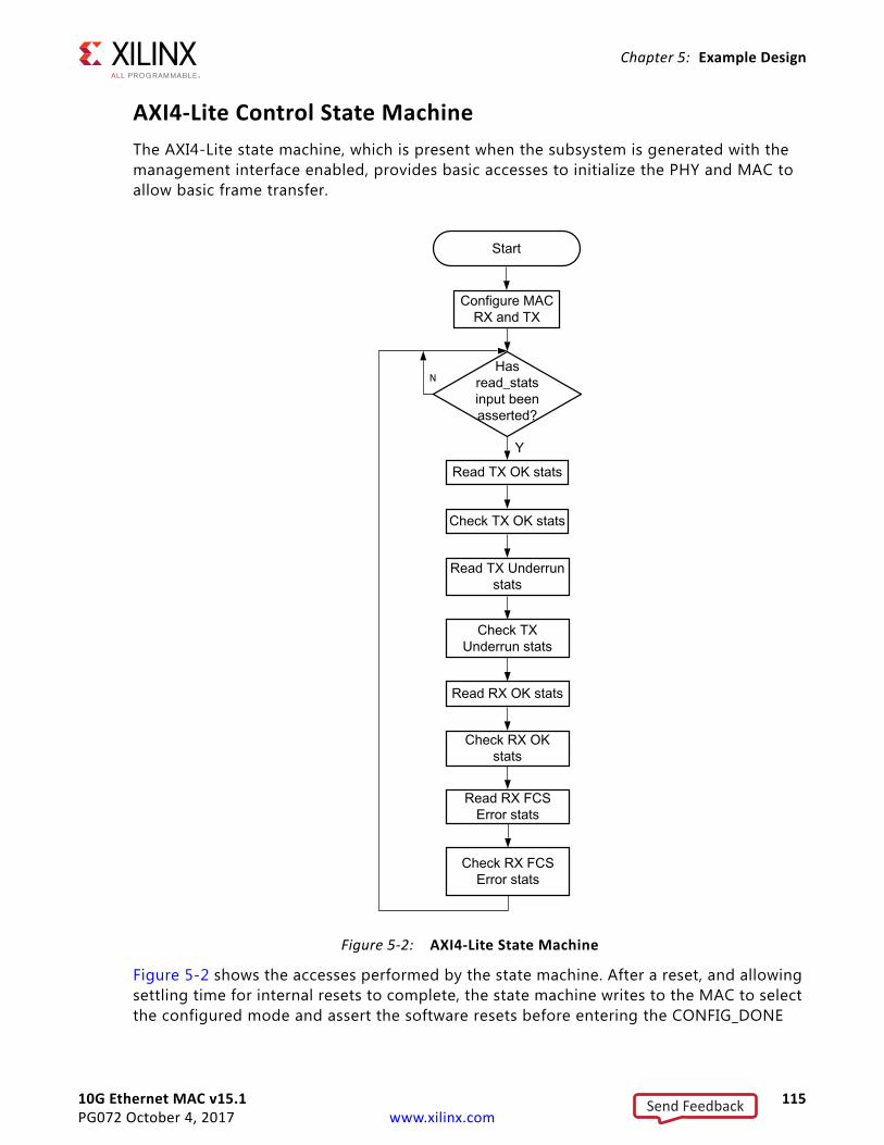
10G Ethernet MAC v15.1 115PG072 October 4, 2017 www.xilinx.com
Chapter 5: Example Design
AXI4-Lite Control State MachineThe AXI4-Lite state machine, which is present when the subsystem is generated with the management interface enabled, provides basic accesses to initialize the PHY and MAC to allow basic frame transfer.
Figure 5-2 shows the accesses performed by the state machine. After a reset, and allowing settling time for internal resets to complete, the state machine writes to the MAC to select the configured mode and assert the software resets before entering the CONFIG_DONE
X-Ref Target - Figure 5-2
Figure 5-2: AXI4-Lite State Machine
Start
Configure MACRX and TX
Y
N
Send Feedback
10G Ethernet MAC v15.1 116PG072 October 4, 2017 www.xilinx.com
Chapter 5: Example Design
state where the pattern generator user control is sampled. The state machine will then remain in this state until either a reset occurs or the read_stats input is asserted at which point the key stats are read and compared against predefined expected values. If any of the stats return an unexpected value then the stats_fail output is asserted to the user. The predefined values are only valid when the demo_tb is used in DEMO mode.
Shared Logic and the Support LayerDepending on the selection made for shared logic in the subsystem customization Vivado IDE, the Support Layer can either itself be the subsystem top-level (Include Shared Logic in core) or can simply contain the subsystem top-level (Include Shared Logic in example design).
The difference is subtle but selecting Include Shared Logic in the core produces a subsystem that includes all the shared logic and has outputs for clocks and control signals that can be shared between multiple 10GBASE-R/KR IP subsystems.
Selecting Include Shared Logic in the Example Design allows you to access the shared logic.
Typically in a multi-subsystem design, you can create one subsystem, subsystem A with Shared Logic included in the subsystem, and one subsystem, subsystem B with the opposite setting. A single instance of subsystem A then provides the clocks for several instances of subsystem B. See Special Design Considerations for more information.
Send Feedback
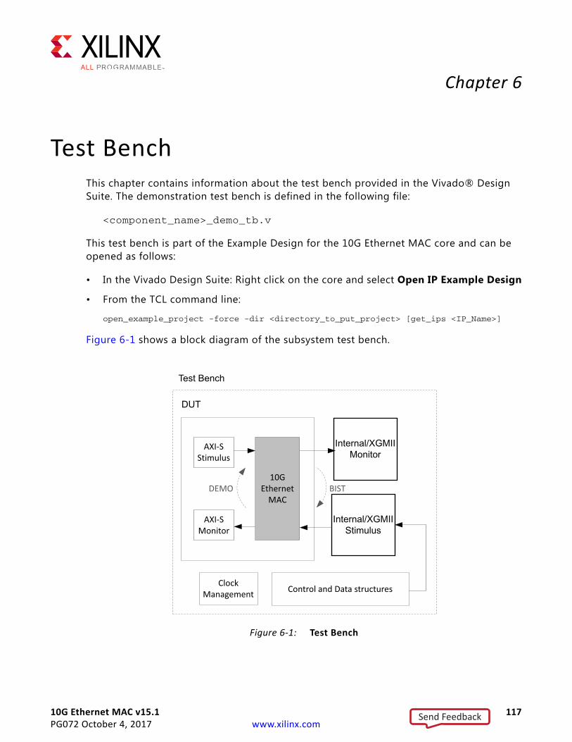
10G Ethernet MAC v15.1 117PG072 October 4, 2017 www.xilinx.com
Chapter 6
Test BenchThis chapter contains information about the test bench provided in the Vivado® Design Suite. The demonstration test bench is defined in the following file:
<component_name>_demo_tb.v
This test bench is part of the Example Design for the 10G Ethernet MAC core and can be opened as follows:
• In the Vivado Design Suite: Right click on the core and select Open IP Example Design
• From the TCL command line:
open_example_project -force -dir <directory_to_put_project> [get_ips <IP_Name>]
Figure 6-1 shows a block diagram of the subsystem test bench.
X-Ref Target - Figure 6-1
Figure 6-1: Test Bench
DUT
Test Bench
ClockManagement
ClockManagement Control and Data structuresControl and Data structures
10GEthernet
MACBISTDEMO
AXI-S Stimulus
AXI-SMonitor
Send Feedback
10G Ethernet MAC v15.1 118PG072 October 4, 2017 www.xilinx.com
Chapter 6: Test Bench
The demonstration test bench is a simple program to exercise the example design and the subsystem itself. It has two modes of operation, DEMO and Built-in Self Test (BIST), with DEMO being the default mode.
The test bench consists of the following:
• Clock generators
• DEMO - A Frame Stimulus block which provides XGMII data to be passed to the MAC.
• DEMO - A Frame Monitor block to check the data returned through the XGMII interface.
• A CRC engine (not illustrated) that is used both by the stimulus and monitor blocks.
• BIST - A simple loopback path (not illustrated) can be connected from the XGMII transmit interface to the XGMII receiver.
DEMO ModeThe demonstration test bench performs the following tasks:
• Input clock signals are generated.
• Address swap is enabled; pattern generator and checker are disabled
• Receive data is looped back into transmit path on the AXI4-Stream interface
• A reset is applied to the example design.
• Four frames are pushed into the XGMII receiver interface
° The first frame is a minimum length frame.
° The second frame is a type frame.
° The third frame is an errored frame.
° The fourth frame is a padded frame.
• As each frame is pushed into the receiver interface a CRC is calculated over the applicable frame fields and appended to the end of the frame.
• The frames are received at the XGMII transmitter interface
• Frames are then passed to the monitor process which calculates the CRC as the frame is being observed. It then checks the validity of the CRC by comparing its own calculated CRC value with the last four bytes of the frame.
• Transmitted frames are counted
BIST ModeThe demonstration test bench performs the following tasks:
Send Feedback
10G Ethernet MAC v15.1 119PG072 October 4, 2017 www.xilinx.com
Chapter 6: Test Bench
• Input clock signals are generated.
• A reset is applied to the example design.
• The pattern generator and checker are enabled.
• The XGMII receiver link is connected to the transmitter link, so that transmitted frames are looped back to the receiver path of the core.
• The frames read out from the RX FIFO are checked by the checker module inside of the example design. The test bench monitors any errors that the checker module detects.
• The edges of the generator and checker activity flash outputs are counted, if these counters remain at zero at the end of the test this is considered to be an error, as no frames were seen.
Changing the Test BenchThe Demonstration test bench defaults to DEMO mode for all implementations.
The mode is set using the TB_MODE parameter in the <component_name>_demo_tb.v. To change the mode, set the parameter value to BIST.
Changing Frame Data in Demo Mode
The contents of the frame data passed into the XGMII receiver can be changed by editing the DATA fields for each frame defined in the test bench. The test bench automatically calculates the new FCS field to pass into the MAC. Further frames can be added by defining a new frame of data.
Changing Frame Length
There are two ways to change the frame lengths of the stimulus frames. The predefined frames within the test bench can be directly edited to change the frame contents and size. Alternatively, the test bench contains a quicker method that allows blocks of data within the predefined frames to be repeated a given number of times. The block of data which can be repeated is inclusive from the beginning of the TYPE/LENGTH field to the end of the final full XGMII column of data payload. The FRAME_GEN_MULTIPLIER constant provides the information for the number of times to repeat this block of data.
For example, if the index of the last complete control (ctrl) column (for example, ctrl column[14] = 4'b1111) then the block size is (14 + 1) - 3 = 12. That means that 12 x 4 = 48 bytes are contained in one block. If FRAME_GEN_MULTIPLIER is set to 2 then 2 x 12 x 4 = 96 bytes are sent after the SA/DA and the same 48 byte block repeating pattern is sent twice.
If using a LENGTH field rather than a TYPE field for the TYPE/LENGTH field of the defined frame, then the LENGTH value must be manually edited. The general formula for LENGTH/TYPE field is as follows:
Send Feedback
10G Ethernet MAC v15.1 120PG072 October 4, 2017 www.xilinx.com
Chapter 6: Test Bench
[[(index of last complete ctrl column+1) - 3] x4 x FRAME_GEN_MULTIPLIER] - 2 + (1, 2 or 3 depending from the value of the ctrl column after the last complete ctrl column).
The multiplier constant is applied to every frame inserted into RX; therefore the L/T field has to be set appropriately for every frame unless the frame is a type or a control frame.
Changing Frame Error Status
Errors can be inserted into any of the pre-defined frames by changing the error field to 1 in any column of that frame. The error currently written into the third frame can be removed by setting the error field for the frame to 0.
Send Feedback
10G Ethernet MAC v15.1 121PG072 October 4, 2017 www.xilinx.com
Appendix A
Verification, Compliance, and Interoperability
This appendix includes information about how the IP was tested for compliance with the protocol to which it was designed.
SimulationThe 10G Ethernet MAC core has been verified in simulation. A highly parameterizable constrained random simulation test suite has been used to verify the core. Tests included:
• Configuration register access through Management Interface
• Local Fault/Remote fault and link interruption handling
• Frame transmission
• Frame reception
• CRC validity
• Handling of CRC errors
• Statistic counter access through Management Interface and validity of counts
• Statistic vector validity
• Initiating MDIO transactions through Management Interface
• Use of custom preamble field
• Variable Frame Length and MTU
Hardware VerificationThe core has been hardware validated on supported devices with the Xilinx LogiCORE™ IP XAUI, RXAUI, DXAUI and 10G Ethernet PCS/PMA cores. The design comprises the Ethernet MAC, PHY core, a ping loopback FIFO, and test pattern generator all under embedded MicroBlaze™ processor control.
Send Feedback
10G Ethernet MAC v15.1 122PG072 October 4, 2017 www.xilinx.com
Appendix B
UpgradingThis appendix contains information about migrating a design from the ISE® Design Suite to the Vivado® Design Suite, and for upgrading to a more recent version of the IP core. For customers upgrading in the Vivado Design Suite, important details (where applicable) about any port changes and other impact to user logic are included.
Migrating to the Vivado Design SuiteFor information on migrating to the Vivado Design Suite, see ISE to Vivado Design Suite Migration Guide (UG911) [Ref 10].
Upgrading in the Vivado Design SuiteThis section provides information about any changes to the user logic or port designations that take place when you upgrade to a more current version of this IP core in the Vivado Design Suite.
Parameter Changes In v12.0, the AXI4-Lite address buses were 32 bits wide and the C_BASE_ADDRESS parameter to the core set the base decoded address for the AXI4-Lite/IPIF bridge logic.
In v13.0, the AXI4-Lite address bus widths have been reduced to 11 bits, which is the address width required for all of the memory mapped registers within the core. It is now required that address decoding is handled externally to the core (for example, by the AXI4 Interconnect IP core in Vivado IP integrator) and that only the lower-order address bits are passed through to the AXI4-Lite/IPIF bridge.
Send Feedback
10G Ethernet MAC v15.1 123PG072 October 4, 2017 www.xilinx.com
Appendix C
Calculating the DCM Fixed Phase-Shift Value
This appendix describes how to calculate the fixed phase-shift value of the Digital Clock Manager (DCM).
Requirement for DCM Phase ShiftingA DCM is used in the receiver clock path to meet the input setup and hold requirements when using the core with an XGMII. In these cases, a fixed phase-shift offset is applied to the receiver clock DCM to skew the clock; this performs static alignment by using the receiver clock DCM to shift the internal version of the receiver clock such that its edges are centered on the data eye at the IOB DDR flip-flops. The ability to shift the internal clock in small increments is critical for sampling high-speed source synchronous signals such as XGMII. For statically aligned systems, the DCM output clock phase offset (as set by the phase-shift value) is a critical part of the system, as is the requirement that the PCB is designed with precise delay and impedance-matching for all the XGMII receiver data bus and control signals.
You must determine the best DCM setting (phase shift) to ensure that the target system has the maximum system margin to perform across voltage, temperature, and process (multiple chips) variations. Testing the system to determine the best DCM phase-shift setting has the added advantage of providing a benchmark of the system margin based on the UI (unit interval or bit time). Equation C-1 defines the system margin.
System Margin (ps) = UI(ps) × (working phase – shift range/128) Equation C-1
Send Feedback
10G Ethernet MAC v15.1 124PG072 October 4, 2017 www.xilinx.com
Appendix C: Calculating the DCM Fixed Phase-Shift Value
Finding the Ideal Phase-Shift Value for Your SystemXilinx cannot recommend a singular phase-shift value that is effective across all hardware families. Xilinx does not recommend attempting to determine the phase-shift setting empirically. In addition to the clock-to-data phase relationship, other factors such as package flight time (package skew) and clock routing delays (internal to the device) affect the clock to data relationship at the sample point (in the IOB) and are difficult to characterize.
RECOMMENDED: Xilinx recommends extensive investigation of the phase-shift setting during hardware integration and debugging. The phase-shift settings provided in the example design constraint file is a placeholder, and works successfully in back-annotated simulation of the example design.
Perform a complete sweep of phase-shift settings during your initial system test. Use only positive (0 to 255) phase-shift settings, and use a test range that covers a range of no less than 128, corresponding to a total 180° of clock offset. This does not imply that 128 phase-shift values must be tested; increments of 4 (52, 56, 60) correspond to roughly one DCM tap, and consequently provide an appropriate step size. Additionally, it is not necessary to characterize areas outside the working phase-shift range.
At the edge of the operating phase-shift range, system behavior changes dramatically. In eight phase-shift settings or less, the system can transition from no errors to exhibiting errors. Checking the operational edge at a step size of two (on more than one board) refines the typical operational phase-shift range. After the range is determined, choose the average of the high and low working phase-shift values as the default.
RECOMMENDED: During the production test, Xilinx recommends that you re-examine the working range at corner case operating conditions to determine whether any final adjustments to the final phase-shift setting are needed.
Send Feedback
10G Ethernet MAC v15.1 125PG072 October 4, 2017 www.xilinx.com
Appendix D
DebuggingThis appendix includes details about resources available on the Xilinx Support website and debugging tools.
TIP: If the IP generation halts with an error, there might be a license issue. See License Checkers in Chapter 1 for more details.
Finding Help on Xilinx.comTo help in the design and debug process when using the 10G Ethernet MAC, the Xilinx Support web page contains key resources such as product documentation, release notes, answer records, information about known issues, and links for obtaining further product support.
DocumentationThis product guide is the main document associated with the 10G Ethernet MAC. This guide, along with documentation related to all products that aid in the design process, can be found on the Xilinx Support web page or by using the Xilinx Documentation Navigator.
Download the Xilinx Documentation Navigator from the Downloads page. For more information about this tool and the features available, open the online help after installation.
Solution CentersSee the Xilinx Solution Centers for support on devices, software tools, and intellectual property at all stages of the design cycle. Topics include design assistance, advisories, and troubleshooting tips.
The Solution Center relevant to Ethernet IP is located at Xilinx Ethernet IP Solution Center.
Answer RecordsAnswer Records include information about commonly encountered problems, helpful information on how to resolve these problems, and any known issues with a Xilinx product.
Send Feedback
10G Ethernet MAC v15.1 126PG072 October 4, 2017 www.xilinx.com
Appendix D: Debugging
Answer Records are created and maintained daily ensuring that users have access to the most accurate information available.
Answer Records for this core can be located by using the Search Support box on the main Xilinx support web page. To maximize your search results, use keywords such as:
• Product name
• Tool message(s)
• Summary of the issue encountered
A filter search is available after results are returned to further target the results.
Master Answer Record for the 10G Ethernet MAC
AR: 54252
Technical SupportXilinx provides technical support in the Xilinx Support web page for this LogiCORE™ IP product when used as described in the product documentation. Xilinx cannot guarantee timing, functionality, or support if you do any of the following:
• Implement the solution in devices that are not defined in the documentation.
• Customize the solution beyond that allowed in the product documentation.
• Change any section of the design labeled DO NOT MODIFY.
To contact Xilinx Technical Support, navigate to the Xilinx Support web page.
Debug ToolsThere are many tools available to debug 10G Ethernet MAC design issues. It is important to know which tools are useful for debugging various situations.
Vivado Design Suite Debug FeatureThe Vivado® Design Suite debug feature inserts logic analyzer and virtual I/O cores directly into your design. The debug feature also allows you to set trigger conditions to capture application and integrated block port signals in hardware. Captured signals can then be analyzed. This feature in the Vivado IDE is used for logic debugging and validation of a design running in Xilinx.
Send Feedback
10G Ethernet MAC v15.1 127PG072 October 4, 2017 www.xilinx.com
Appendix D: Debugging
The Vivado logic analyzer is used with the logic debug IP cores, including:
• ILA 2.0 (and later versions)
• VIO 2.0 (and later versions)
See the Vivado Design Suite User Guide, Programming and Debugging (UG908) [Ref 12].
Simulation DebugThe simulation debug flow for Mentor Graphics Questa Simulator (QuestaSim) is shown in Figure D-1. A similar approach can be used with other simulators.
Send Feedback
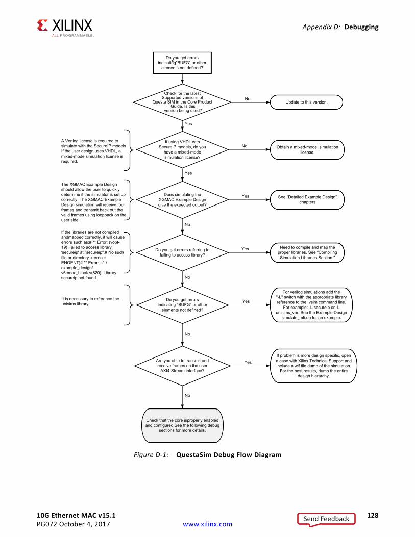
10G Ethernet MAC v15.1 128PG072 October 4, 2017 www.xilinx.com
Appendix D: Debugging
X-Ref Target - Figure D-1
Figure D-1: QuestaSim Debug Flow Diagram
Send Feedback
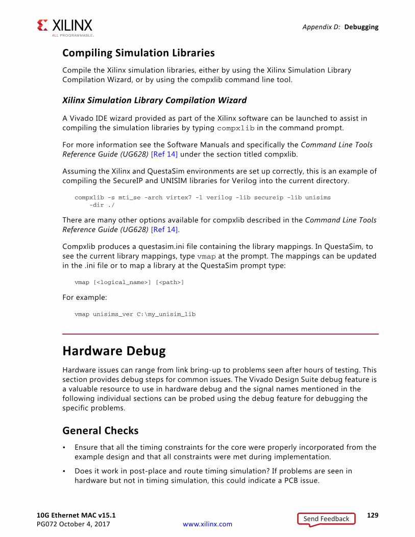
10G Ethernet MAC v15.1 129PG072 October 4, 2017 www.xilinx.com
Appendix D: Debugging
Compiling Simulation LibrariesCompile the Xilinx simulation libraries, either by using the Xilinx Simulation Library Compilation Wizard, or by using the compxlib command line tool.
Xilinx Simulation Library Compilation Wizard
A Vivado IDE wizard provided as part of the Xilinx software can be launched to assist in compiling the simulation libraries by typing compxlib in the command prompt.
For more information see the Software Manuals and specifically the Command Line Tools Reference Guide (UG628) [Ref 14] under the section titled compxlib.
Assuming the Xilinx and QuestaSim environments are set up correctly, this is an example of compiling the SecureIP and UNISIM libraries for Verilog into the current directory.
compxlib -s mti_se -arch virtex7 -l verilog -lib secureip -lib unisims -dir ./
There are many other options available for compxlib described in the Command Line Tools Reference Guide (UG628) [Ref 14].
Compxlib produces a questasim.ini file containing the library mappings. In QuestaSim, to see the current library mappings, type vmap at the prompt. The mappings can be updated in the .ini file or to map a library at the QuestaSim prompt type:
vmap [<logical_name>] [<path>]
For example:
vmap unisims_ver C:\my_unisim_lib
Hardware DebugHardware issues can range from link bring-up to problems seen after hours of testing. This section provides debug steps for common issues. The Vivado Design Suite debug feature is a valuable resource to use in hardware debug and the signal names mentioned in the following individual sections can be probed using the debug feature for debugging the specific problems.
General Checks• Ensure that all the timing constraints for the core were properly incorporated from the
example design and that all constraints were met during implementation.
• Does it work in post-place and route timing simulation? If problems are seen in hardware but not in timing simulation, this could indicate a PCB issue.
Send Feedback
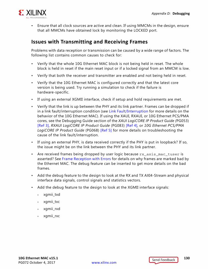
10G Ethernet MAC v15.1 130PG072 October 4, 2017 www.xilinx.com
Appendix D: Debugging
• Ensure that all clock sources are active and clean. If using MMCMs in the design, ensure that all MMCMs have obtained lock by monitoring the LOCKED port.
Issues with Transmitting and Receiving FramesProblems with data reception or transmission can be caused by a wide range of factors. The following list contains common causes to check for:
• Verify that the whole 10G Ethernet MAC block is not being held in reset. The whole block is held in reset if the main reset input or if a locked signal from an MMCM is low.
• Verify that both the receiver and transmitter are enabled and not being held in reset.
• Verify that the 10G Ethernet MAC is configured correctly and that the latest core version is being used. Try running a simulation to check if the failure is hardware-specific.
• If using an external XGMII interface, check if setup and hold requirements are met.
• Verify that the link is up between the PHY and its link partner. Frames can be dropped if in a link fault/interruption condition (see Link Fault/Interruption for more details on the behavior of the 10G Ethernet MAC). If using the XAUI, RXAUI, or 10G Ethernet PCS/PMA cores, see the Debugging Guide section of the XAUI LogiCORE IP Product Guide (PG053) [Ref 3], RXAUI LogiCORE IP Product Guide (PG083) [Ref 4], or 10G Ethernet PCS/PMA LogiCORE IP Product Guide (PG068) [Ref 5] for more details on troubleshooting the cause of the link fault/interruption.
• If using an external PHY, is data received correctly if the PHY is put in loopback? If so, the issue might be on the link between the PHY and its link partner.
• Are received frames being dropped by user logic because rx_axis_mac_tuser is asserted? See Frame Reception with Errors for details on why frames are marked bad by the Ethernet MAC. The debug feature can be inserted to get more details on the bad frames.
• Add the debug feature to the design to look at the RX and TX AXI4-Stream and physical interface data signals, control signals and statistics vectors.
• Add the debug feature to the design to look at the XGMII interface signals:
° xgmii_txd
° xgmii_txc
° xgmii_rxd
° xgmii_rxc
Send Feedback
10G Ethernet MAC v15.1 131PG072 October 4, 2017 www.xilinx.com
Appendix D: Debugging
Issues with the MDIOSee MDIO Interface for detailed information about performing MDIO transactions.
Check the following:
• Check that the MDC clock is running and that the frequency is 2.5 MHz or less. If using the MDIO control registers to perform MDIO accesses, the MDIO interface does not work until the clock frequency is set with CLOCK_DIVIDE. The MDIO clock with a maximum frequency of 2.5 MHz is derived from the s_axi_aclk clock.
• Ensure that the MAC and PHY are not held in reset. Be sure to check the polarity of the reset to your external PHY. Many PHYs have an active-low reset.
• Read from a configuration register that does not have all 0s as a default. If all 0s are read back, the read was unsuccessful.
• If using the management interface to access the MDIO, check if the issue is just with the MDIO control registers or if there are also issues reading and writing MAC registers with the management interface.
• If accessing MDIO registers of the Ethernet 10G Ethernet PCS/PMA, XAUI or RXAUI core, check that the PHYAD field placed into the MDIO frame matches the value placed on the phyad[4:0] port of the PHY core.
• Has a simulation been run? Verify in simulation and/or a debug feature capture that the waveform is correct for accessing the management interface for a MDIO read/write. The demonstration test bench delivered with the core provides an example of MDIO accesses.
Link Fault/InterruptionThe 10G Ethernet MAC contains a Link Fault State machine as described in the IEEE 802.3-2012 standard. This mandates that:
• When a MAC receives Local Fault (LF) or Link Interrupt ordered sets, it continuously transmits Remote Fault (RF) ordered sets;
• When a MAC receives a Remote Fault, it continuously transmits Idle ordered sets.
This latter fault mode can be interpreted as inactivity on the part of the MAC; if no traffic is appearing on the XGMII interface in the transmit direction, check the fault state in the management registers.
For more information, see Transmission of Frames During Local/Remote Fault or Link Interruption Reception.
Send Feedback
10G Ethernet MAC v15.1 132PG072 October 4, 2017 www.xilinx.com
Appendix D: Debugging
Data ThroughputThe 10G Ethernet MAC is capable of running at the maximum throughput designed by the IEEE specification. If maximum throughput is not being seen on transmission:
• Check that back-to-back frames are being presented on the AXI interface. For more information, see Back-to-Back Continuous Transfers.
• Check if Deficit Idle Count has been enabled to reduce average IFG transmitted. For more information, see Deficit Idle Count (DIC).
Interface Debug
AXI4-Lite InterfacesRead from a register that does not have all 0s as a default to verify that the interface is functional. See Figure 3-43 for a read timing diagram. Output s_axi_arready asserts when the read address is valid, and output s_axi_rvalid asserts when the read data/response is valid. If the interface is unresponsive, ensure that the following conditions are met:
• The s_axi_aclk and aclk inputs are connected and toggling.
• The interface is not being held in reset, and s_axi_areset is an active-Low reset.
• The interface is enabled, and s_axi_aclken is active-High (if used).
• The main core clocks are toggling and that the enables are also asserted.
• If the simulation has been run, verify in simulation and/or a Vivado Design Suite debug feature capture that the waveform is correct for accessing the AXI4-Lite interface.
AXI4-Stream InterfacesIf data is not being transmitted or received, check the following conditions.
• If transmit <interface_name>_tready is stuck Low following the <interface_name>_tvalid input being asserted, the core cannot send data.
• If the receive <interface_name>_tvalid is stuck Low, the core is not receiving data.
• Check that the ACLK inputs are connected and toggling.
• Check that the AXI4-Stream waveforms are being followed (see timing diagrams in Chapter 3, Designing with the Core).
• Check core configuration.
Send Feedback

10G Ethernet MAC v15.1 133PG072 October 4, 2017 www.xilinx.com
Appendix E
Additional Resources and Legal Notices
Xilinx ResourcesFor support resources such as Answers, Documentation, Downloads, and Forums, see Xilinx Support.
Documentation Navigator and Design HubsXilinx® Documentation Navigator provides access to Xilinx documents, videos, and support resources, which you can filter and search to find information. To open the Xilinx Documentation Navigator (DocNav):
• From the Vivado® IDE, select Help > Documentation and Tutorials.
• On Windows, select Start > All Programs > Xilinx Design Tools > DocNav.
• At the Linux command prompt, enter docnav.
Xilinx Design Hubs provide links to documentation organized by design tasks and other topics, which you can use to learn key concepts and address frequently asked questions. To access the Design Hubs:
• In the Xilinx Documentation Navigator, click the Design Hubs View tab.
• On the Xilinx website, see the Design Hubs page.
Note: For more information on Documentation Navigator, see the Documentation Navigator page on the Xilinx website.
ReferencesThese documents provide supplemental material useful with this product guide:
1. IEEE Standard 802.3-2012, “Carrier Sense Multiple Access with Collision Detection (CSMA/CD) Access Method and Physical Layer Specifications” (standards.ieee.org/findstds/standard/802.3-2012.html)
Send Feedback
10G Ethernet MAC v15.1 134PG072 October 4, 2017 www.xilinx.com
Appendix E: Additional Resources and Legal Notices
2. IEEE Standard 802.1Qbb, “IEEE Standard for Local and Metropolitan Area Networks—Virtual Bridged Local Area Networks—Amendment: Priority-based Flow Control” (standards.ieee.org/findstds/standard/802.1Qbb-2011.html)
3. XAUI Product Guide (PG053)
4. RXAUI LogiCORE IP Product Guide (PG083)
5. 10G Ethernet PCS/PMA LogiCORE IP Product Guide (PG068)
6. Vivado Design Suite User Guide, Designing IP Subsystems Using IP Integrator (UG994)
7. Vivado Design Suite User Guide, Designing with IP (UG896)
8. Vivado Design Suite User Guide, Getting Started (UG910)
9. Vivado Design Suite User Guide, Logic Simulation (UG900)
10. ISE to Vivado Design Suite Migration Guide (UG911)
11. 10G AXI Ethernet Subsystem Product Guide (PG157)
12. Vivado Design Suite User Guide, Programming and Debugging (UG908)
13. Ethernet 1000BASE-X PCS/PMA or SGMII LogiCORE IP Product Guide (PG047)
14. Command Line Tools User Guide (UG628)
Revision HistoryThe following table shows the revision history for this document.
Date Version Revision
10/04/2017 15.1 Corrected the descriptions for RX Quanta decrement process
10/05/2016 15.1 Minor updates to clarify core operation
04/06/2016 15.1 • Added Link Interruption detection description
• Update description in Ethernet FIFO section
• Removed support for UltraScale+ families
11/18/2015 15.0 Added support for UltraScale+ families
09/30/2015 15.0 • Minor document updates
04/01/2015 15.0 • Merged 32-bit and 64-bit datapath sections to remove functional differences
• Updated resources table to use UltraScale devices
Send Feedback
10G Ethernet MAC v15.1 135PG072 October 4, 2017 www.xilinx.com
Appendix E: Additional Resources and Legal Notices
10/01/2014 14.0 • Added separate 64-bit datapath and 32-bit low latency datapath sections for both RX and TX
• Updated MDIO read data register description
• Updated example design
• Updated demonstration test bench
• Updated reset logic diagram
04/02/2014 13.1 • Added Priority Flow Control description
• Added new functionality description to 802.3 Pause control description
• Updated Demonstration test bench
• Updated graphics for interfacing to other cores
• Updated length check description
10/02/2013 13.0 Revision number advanced to 13.0 to align with core version number.
• Added IP Integrator.
• Added License Checkers section.
• Updated Resource Utilization section.
• Updated Table 2-6: Management Interface Port Descriptions.
• Updated to six clocks in Transmit Path Latency section.
• Updated tables in Clocking and Reset Signals section.
• Added Shared Logic section.
• Updated description in Receive section.
• Updated Fig. 3-41 Clock Management, Multiple Instances of the Core with XGMII.
• Updated shared clocking in Interfacing to the XAUI IP Core, Interfacing with the RXAUI Core, and 10 Gigabit Ethernet PCS/PMA Core sections.
• Updated Fig. 3-44 10 Gigabit Ethernet MAC Core Integrated with PCS/PMA Core – Virtex-7 and Kintex-7 FPGAs.
• Updated Fig. 4-1 and added Shared Logic in Customizing and Generating the Core.
• Added Simulation and Synthesis chapters.
• Updated supported devices in Hardware Verification section in Verify Appendix.
• Updated Migration Appendix.
• Updated Debug Appendix.
Date Version Revision
Send Feedback
10G Ethernet MAC v15.1 136PG072 October 4, 2017 www.xilinx.com
Appendix E: Additional Resources and Legal Notices
03/20/2013 2.1 • Updated core to v12.0 and this release is for Vivado Design Suite only.
• Updated Fig. 1-1 Implementation of the 10 Gigabit Ethernet MAC Core.
• Updated Fig. 2-2 Implementation of the Core with User Logic on PHY Interface.
• Updated tx_axis_tuser[0:0] in Table 2-2 AXI4-Stream Interface Ports – Transmit.
• Updated Table 2-5 PHY Interface Port Descriptions.
• Updated to 300 MHz in Table 2-6 Management Interface Port Descriptions.
• Updated Table 2-11 Clock, Clock Management, and Reset Ports.
• Updated Fig. 3-1 Clocking Logic for the Ethernet MAC Internal Interface Option.
• Updated to 300 MHz in Table 3-6 Management Interface Port Description.
• Added Bit[31] in Table 3-10 tx_configuration_vector Bit Definitions.
• Added Bit[31] in Table 3-11 rx_configuration_vector Bit Definitions.
• Updated Bits[19:5] in Table 3-13 Transmit Statistics Vector Bit Description.
• Updated Fig. 3-38 Clock Management, Multiple Instances of the Core with XGMII.
• Updated GUI in Fig. 4-1.
• Added description in Required Constraints.
• Updated Fig. 6-1 Example Design and HDL Wrapper for 10 Gigabit Ethernet MAC with XGMII Interface.
• Updated to QuestaSim.
12/18/2012 2.0 • Updated core to v11.5 and this release is for Vivado Design Suite v2012.4 only.
• Updated License and Ordering Information.
• Updated to support 7 series FPGAs only.
• Updated tx_axis_tready direction to out in Table 3-1.
• Updated Fig. 4-1 GUI and WAN support description.
• Updated Migrating Appendix.
• Added new Debug section and minor document updates.
07/25/2012 1.0 Initial Xilinx release. This release is for ISE Design Suite v14.2 and Vivado Design Suite v2012.2. The core version is v11.4. This document replaces UG773, LogiCORE IP 10 Gigabit Ethernet MAC User Guide, and DS813, LogiCORE IP 10 Gigabit Ethernet MAC Data Sheet.
Date Version Revision
Send Feedback
10G Ethernet MAC v15.1 137PG072 October 4, 2017 www.xilinx.com
Appendix E: Additional Resources and Legal Notices
Please Read: Important Legal NoticesThe information disclosed to you hereunder (the "Materials") is provided solely for the selection and use of Xilinx products. To the maximum extent permitted by applicable law: (1) Materials are made available "AS IS" and with all faults, Xilinx hereby DISCLAIMS ALL WARRANTIES AND CONDITIONS, EXPRESS, IMPLIED, OR STATUTORY, INCLUDING BUT NOT LIMITED TO WARRANTIES OF MERCHANTABILITY, NON-INFRINGEMENT, OR FITNESS FOR ANY PARTICULAR PURPOSE; and (2) Xilinx shall not be liable (whether in contract or tort, including negligence, or under any other theory of liability) for any loss or damage of any kind or nature related to, arising under, or in connection with, the Materials (including your use of the Materials), including for any direct, indirect, special, incidental, or consequential loss or damage (including loss of data, profits, goodwill, or any type of loss or damage suffered as a result of any action brought by a third party) even if such damage or loss was reasonably foreseeable or Xilinx had been advised of the possibility of the same. Xilinx assumes no obligation to correct any errors contained in the Materials or to notify you of updates to the Materials or to product specifications. You may not reproduce, modify, distribute, or publicly display the Materials without prior written consent. Certain products are subject to the terms and conditions of Xilinx's limited warranty, please refer to Xilinx's Terms of Sale which can be viewed at https://www.xilinx.com/legal.htm#tos; IP cores may be subject to warranty and support terms contained in a license issued to you by Xilinx. Xilinx products are not designed or intended to be fail-safe or for use in any application requiring fail-safe performance; you assume sole risk and liability for use of Xilinx products in such critical applications, please refer to Xilinx's Terms of Sale which can be viewed at https://www.xilinx.com/legal.htm#tos.AUTOMOTIVE APPLICATIONS DISCLAIMERAUTOMOTIVE PRODUCTS (IDENTIFIED AS “XA” IN THE PART NUMBER) ARE NOT WARRANTED FOR USE IN THE DEPLOYMENT OF AIRBAGS OR FOR USE IN APPLICATIONS THAT AFFECT CONTROL OF A VEHICLE (“SAFETY APPLICATION”) UNLESS THERE IS A SAFETY CONCEPT OR REDUNDANCY FEATURE CONSISTENT WITH THE ISO 26262 AUTOMOTIVE SAFETY STANDARD (“SAFETY DESIGN”). CUSTOMER SHALL, PRIOR TO USING OR DISTRIBUTING ANY SYSTEMS THAT INCORPORATE PRODUCTS, THOROUGHLY TEST SUCH SYSTEMS FOR SAFETY PURPOSES. USE OF PRODUCTS IN A SAFETY APPLICATION WITHOUT A SAFETY DESIGN IS FULLY AT THE RISK OF CUSTOMER, SUBJECT ONLY TO APPLICABLE LAWS AND REGULATIONS GOVERNING LIMITATIONS ON PRODUCT LIABILITY.© Copyright 2012–2017 Xilinx, Inc. Xilinx, the Xilinx logo, Artix, ISE, Kintex, Spartan, Virtex, Vivado, Zynq, and other designated brands included herein are trademarks of Xilinx in the United States and other countries. AMBA, AMBA Designer, ARM, ARM1176JZ-S, CoreSight, Cortex, PrimeCell, and MPCore are trademarks of ARM in the EU and other countries. All other trademarks are the property of their respective owners.
Send Feedback