lms100/111/120 laser measurement systems -...
TRANSCRIPT
O N L I N E H E L P
LMS100/111/120
Laser Measurement Systems
Convenient Measurement Systems
with Double-pulse Technology
Software version Online Help
LMS100/LMS111/LMS120 Laser Measurement Systems
LMS100/LMS111/LMS120 Software version describedSoftware/tool Function StatusDevice description LMS100_FieldEval
Device specific software module for SOPAS ET
V 01.10.00 or higher
SOPAS ET Configuration software V 02.18 or higher
Copyright
Copyright © 2008SICK AG WaldkirchAuto Ident, Reute PlantNimburger Straße 1179276 ReuteGermany
Trademarks
Windows 2000™, Windows XP™, Windows Vista™ and Internet Explorer™ are registered trademarks of Microsoft Corporation in the USA and other countries.
Acrobat® Reader™ is a trademark of Adobe Systems Incorporated.
2 © SICK AG · Division Auto Ident · Germany · All rights reserved 8012473/SI79/2008-12-05
Online Help
LMS100/LMS111/LMS120
Contents
Table of contents1 About this document .......................................................................................................61.1 Function of this document .......................................................................................... 61.2 Target group ................................................................................................................ 61.3 Depth of information ................................................................................................... 61.4 Symbology used .......................................................................................................... 62 For your safety .................................................................................................................72.1 Authorised personnel .................................................................................................. 72.2 General safety notes and protective measures ........................................................ 73 Configuration ....................................................................................................................83.1 Preparing the configuration ........................................................................................ 93.2 Basic parameters ........................................................................................................ 93.3 Filter ...........................................................................................................................133.4 Increment source ...................................................................................................... 143.5 Evaluation fields ........................................................................................................163.6 Evaluation cases .......................................................................................................353.7 Data processing ........................................................................................................393.8 Network/interfaces/inputs and outputs .................................................................404 Monitor ........................................................................................................................... 474.1 Field evaluation monitor ........................................................................................... 474.2 Field evaluation logging ............................................................................................485 Service/system status ................................................................................................. 495.1 LMS status .................................................................................................................495.2 Contamination ...........................................................................................................495.3 Encoder status ..........................................................................................................505.4 Operating data ...........................................................................................................506 Glossary ......................................................................................................................... 527 Index ............................................................................................................................... 53
8012473/SI79/2008-12-05 © SICK AG · Division Auto Ident · Germany · All rights reserved 3

Figures and tables Online Help
LMS100/LMS111/LMS120 Laser Measurement Systems
AbbreviationsBCC Block character check
CAN Controller area network = standardised fieldbus system with message-based protocol for exchanging data
CS Checksum
EEPROM Electrically erasable programmable read-only memory
HTML Hypertext markup language = page description language on the Internet
LED Light Emitting Diode
LMS SICK AG laser measurement system
RAM Random access memory = volatile memory with direct access
ROM Read-only memory (permanent)
SOPAS ET SICK OPEN PORTAL for APPLICATION and SYSTEMS ENGINEERING TOOL = configuration software for the configuration of the LMS100/LMS111/LMS120
TablesTab. 1: Passwords ................................................................................................................ 8
Tab. 2: Buttons for managing the evaluation fields .........................................................16
Tab. 3: Buttons for changing the field editor view ...........................................................18
Tab. 4: Buttons for managing the evaluation cases ........................................................35
Tab. 5: Input combination examples .................................................................................36
Tab. 6: Buttons for controlling the field evaluation logging .............................................48
Figures Fig. 1: Starting angle and stopping angle for the measurement ...................................11
Fig. 2: Effect of the digital filters ......................................................................................13
Fig. 3: Selection of the method for adding an evaluation field ......................................17
Fig. 4: Enlarging the field editor view with the mouse ....................................................19
Fig. 5: Setting end points for a field .................................................................................19
Fig. 6: Setting end points — step 1 ...................................................................................20
Fig. 7: Setting end points — step 2 ...................................................................................20
Fig. 8: Moving end points — step 1 ..................................................................................21
Fig. 9: Moving end points — step 2 ..................................................................................21
Fig. 10: Deleting end points — step 1 ................................................................................22
Fig. 11: Deleting end points — step 2 ................................................................................22
Fig. 12: Start points for a field ............................................................................................23
Fig. 13: Moving a rectangular field .....................................................................................24
Fig. 14: Increasing or reducing the size of a rectangular field .........................................24
Fig. 15: Rotating a rectangular field ...................................................................................25
Fig. 16: Editing entries for rectangular evaluation field ....................................................25
Fig. 17: View of a dynamic field in the field editor ............................................................26
Fig. 18: Moving a dynamic field ..........................................................................................26
Fig. 19: Enlarging or reducing the basic field for a dynamic evaluation field .................27
4 © SICK AG · Division Auto Ident · Germany · All rights reserved 8012473/SI79/2008-12-05
Online Help
LMS100/LMS111/LMS120
Figures and tables
Fig. 20: Increasing or decreasing the maximum length of a dynamic evaluation field .. 27
Fig. 21: Editing dynamic evaluation field entry ................................................................. 28
Fig. 22: Start angle and end angle for teaching-in an evaluation field ........................... 29
Fig. 23: Radial distance of an evaluation field to the scanned contour ......................... 29
Fig. 24: Distance to the start points for a taught-in field ................................................. 31
Fig. 25: Start angle and end angle during teach-in .......................................................... 32
Fig. 26: Distance to the start points for a taught-in field ................................................. 33
Fig. 27: Distance to the start points for a manually edited field ..................................... 34
Fig. 28: Distance-dependent pixel evaluation ................................................................... 37
Fig. 29: Distance-dependent evaluation of two objects ................................................... 38
Fig. 30: Selection of the indication on the monitor .......................................................... 47
8012473/SI79/2008-12-05 © SICK AG · Division Auto Ident · Germany · All rights reserved 5
Chapter 1 About this document Online Help
Laser measurement systems LMS100/LMS111/LMS120
1 About this document
Please read this chapter carefully before working with this documentation and the LMS laser measurement system.
1.1 Function of this document
This document provides technical personnel information on the configuration and diagnos-tics on the LMS laser measurement system using the SOPAS ET configuration software.
1.2 Target group
The target group for this document are people such as technicians, service technicians and engineers who configure and perform diagnostics on the LMS.
1.3 Depth of information
This document contains information on the configuration, diagnostics and troubleshooting on the LMS laser measurement system with the aid of the SOPAS ET configuration software.
Planning and using measurement systems such as the LMS also require specific technical skills which are not detailed in this documentation.
When operating the LMS laser measurement system, the national, local and statutory rules and regulations must be observed.
1.4 Symbology used
Reference Text in italics indicates a reference to more detailed information.
Recommendation Recommendations are designed to give you assistance in the decision-making process with respect to a certain function or a technical measure.
Important Sections marked "Important" provide information about special features of the device.
Explanation Explanations provide background knowledge on technical relationships.
MENU COMMAND This typeface indicates a term in the SOPAS ET user interface.
Terminal output This typeface indicates messages that the LMS outputs via its terminal interface.
� Take action … Instructions for taking action are shown by an arrow. Read carefully and follow the instructions for action.
This symbol refers to additionally available documentation.
Warning!
A warning indicates an actual or potential hazard. They are designed to help you to prevent accidents and to protect the device from being damaged.
Read carefully and follow the warning notices!
Software notes show you where the related setting can be made in SOPAS ET.
6 © SICK AG · Division Auto Ident · Germany · All rights reserved 8012473/SI79/2008-12-05
Online Help
LMS100/LMS111/LMS120
For your safety Chapter 2
2 For your safety
This chapter deals with your own safety and the safety of the equipment operators.
� Please read this chapter carefully before configuring the LMS.
2.1 Authorised personnel
The LMS laser measurement system must be configured and commissioned only by adequately qualified personnel.
The following qualifications are necessary for the various tasks:
• knowledge on the use and operation of devices in the related application (e.g. conveyors)
• knowledge on the software and hardware environment in the related application (e.g. conveyors)
• basic knowledge of the Windows operating system
• basic knowledge of an HTML browser (e.g. Internet Explorer)
• basic knowledge of data transmission
2.2 General safety notes and protective measures
Safety notes
Please observe the following items in order to ensure the correct and safe use of the LMS laser measurement system.
• The notices in this online help (e.g. on use, mounting, installation or integration into the existing machine controller) must be observed.
• National/international rules and regulations apply to the installation, commissioning, use and periodic technical inspections of the laser measurement system, in particular:
– the work safety regulations/safety rules– other relevant health and safety regulations
• Manufacturers and users of the system are responsible for obtaining and observing all applicable safety regulations and rules.
• The tests must be carried out by specialist personnel or specially qualified and authorised personnel and must be recorded and documented to ensure that the tests can be reconstructed and retraced at any time.
8012473/SI79/2008-12-05 © SICK AG · Division Auto Ident · Germany · All rights reserved 7
Chapter 3 Configuration Online Help
Laser measurement systems LMS100/LMS111/LMS120
3 Configuration
The LMS laser measurement system is adapted to the on-site measurement situation by means of the configuration. You can configure and test the measurement properties, the analysis behaviour and the output properties of the system as required.
Password protection
Software access to the LMS is password protected. As supplied the following passwords are defined:
Save parameters permanently
The data are initially saved in the RAM of the LMS so that you can check the effect immediately. On completion of the configuration, you must save the parameters permanently in the EEPROM of the LMS.
How to save the parameters permanently in the LMS:
Save configuration
The configuration data can be saved in a project file so they can be transferred, for example, to an identical LMS. Additionally, you can save the configuration data as PDF.
How to save the configuration data to a file or as PDF:
Resetting configuration
Recommendation To reset the LMS to the default delivery status, you should first export the device data to a file from a device that is in the default delivery status. You can then subsequently load these device data into an already configured device to reset its configuration to the default delivery status.
Do not switch off the voltage supply during configuration!
Switching off the voltage supply during configuration causes all parameters already configured to be lost.
User level PasswordMaintenance personnel mainAuthorised client client
Tab. 1: Passwords
� From the LMS100_FIELDEVAL menu, choose the command PARAMETER, SAVE PERMANENTLY.
In this way the parameters are saved in the EEPROM in the LMS and will also be available after the device is switched off and on again.
� From the PROJECT menu, choose the command SAVE PROJECT.
� From the PROJECT menu, choose the command PRINT, SAVE AS PDF.
8 © SICK AG · Division Auto Ident · Germany · All rights reserved 8012473/SI79/2008-12-05
Online Help
LMS100/LMS111/LMS120
Configuration Chapter 3
How to reset the configuration of the LMS:
3.1 Preparing the configuration
To configure the LMS laser measurement system, you need:
• SOPAS ET configuration software on CDROM
• PC/notebook (not in the delivery)
– with a standard Intel Pentium PC or compatible, at least Pentium III, 500 MHz– minimum 256 MB RAM, 512 MB RAM recommended– data interface RS232 or Ethernet– operating system: MS Windows 2000, XP or VISTA– monitor with 256 colours minimum, 65.536 colours recommended
(16 Bit High Color), screen resolution 800 × 600 minimum– hard disc: minimum 170 MB free memory – CD-ROM drive – HTML browser on PC, e.g. Internet Explorer™, for the online help system for SOPAS ET
• connecting cable between PC and LMS
How to prepare the configuration:
� Ensure that the LMS laser measurement system has been correctly assembled and that the electrical connections are also correct.
� Plan all the necessary adjustments.
� Install the provided SOPAS ET configuration software from CDROM.
3.2 Basic parameters
3.2.1 Current configuration
The CURRENT CONFIGURATION area indicates the currently set scan frequency and angular resolution.
Important Values are only displayed if you configure a device online, that is the PC is connected to the device.
How to display the current device parameters:
� In the PROJECT menu, choose the command EXPORT DEVICE.
� Save the SOPAS ET device file on a suitable drive, e.g. as BASIC_CONFIGURATION.SDV.
� On an already configured device, choose on the EDIT menu, the LOAD DEVICE DATA TO PROJECT command.
� Choose the device data saved, e.g. as BASIC_CONFIGURATION.SDV.
The parameters for the LMS are overwritten with the parameters from the default delivery status.
� In the PROJECT TREE, LMS100_FIELDEVAL, PARAMETER, open the device page BASIC PARAMETERS.
The CURRENT CONFIGURATION area indicates the currently set SCAN FREQUENCY and ANGULAR RESOLUTION.
8012473/SI79/2008-12-05 © SICK AG · Division Auto Ident · Germany · All rights reserved 9
Chapter 3 Configuration Online Help
Laser measurement systems LMS100/LMS111/LMS120
3.2.2 New configuration
In the NEW CONFIGURATION area you can configure the scanning frequency and the angular resolution and transfer these parameters to the LMS.
Scanning frequency
The LMS scans with a scanning frequency of 25 or 50 Hz. At the higher scanning frequency the LMS supplies more measured values per time unit.
Angular resolution
The LMS scans with an angular resolution of 0.25° or 0.50°. At the finer angular resolution, the LMS supplier more measured values per scan.
Valid combinations and return values
There are three valid combinations of scanning frequency and angular resolution:
• 50 Hz and 0.5°
• 25 Hz and 0.5°
• 25 Hz and 0.25°
After the transfer of the values the LMS may return an error value to SOPAS ET in certain circumstances. This situation has the following possible meanings:
• no error, parameters have been accepted by the LMS
• invalid scanning frequency
• invalid angular resolution
• invalid combination
� If an invalid value is returned, then check the scanning frequency or/and angular resolution entry.
10 © SICK AG · Division Auto Ident · Germany · All rights reserved 8012473/SI79/2008-12-05
Online Help
LMS100/LMS111/LMS120
Configuration Chapter 3
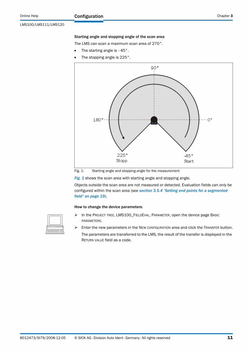
Starting angle and stopping angle of the scan area
The LMS can scan a maximum scan area of 270°.
• The starting angle is –45°.
• The stopping angle is 225°.
Fig. 1: Starting angle and stopping angle for the measurement
Fig. 1 shows the scan area with starting angle and stopping angle.
Objects outside the scan area are not measured or detected. Evaluation fields can only be configured within the scan area (see section 3.5.4 “Setting end points for a segmented field” on page 19).
How to change the device parameters:
� In the PROJECT TREE, LMS100_FIELDEVAL, PARAMETER, open the device page BASIC PARAMETERS.
� Enter the new parameters in the NEW CONFIGURATION area and click the TRANSFER button.
The parameters are transferred to the LMS, the result of the transfer is displayed in the RETURN VALUE field as a code.
8012473/SI79/2008-12-05 © SICK AG · Division Auto Ident · Germany · All rights reserved 11
Chapter 3 Configuration Online Help
Laser measurement systems LMS100/LMS111/LMS120
3.2.3 Measurement
You can start and stop the LMS measurement manually or switch to the stand-by mode. As an alternative you can start the measurement automatically when the LMS is started.
How to start and stop the measurement:
3.2.4 Contamination measurement
The contamination measurement for the optics cover can be configured in SOPAS ET. The result of the measurement can be read from the LMS using a message (see chapter "Annex" in the operating instructions for the LMS). In addition the contamination is displayed in SOPAS ET on the SERVICE device page (see section 5.2 “Contamination” on page 49).
To configure the contamination measurement, first define a strategy. The following strategies can be selected:
• inactiveno contamination measurement
• highly availablehighest contamination tolerance
• available medium contamination tolerance
• sensitivelowest contamination tolerance
For the strategy you must define the response time for the contamination measurement between 0 s and 60 s. If, for instance, you enter 5 s, then the device only switches to the fault state after 5 s. It is therefore possible for contamination, e.g. due to snow, to wipe away.
You can also define the thresholds from which a contamination warning or a contamination error is output.
For the two thresholds you must enter the remaining visibility in %.
How to configure the contamination measurement:
� In the PROJECT TREE, LMS100_FIELDEVAL, PARAMETER, open the device page BASIC PARAMETERS.
� In the MEASUREMENT area, click the START button.
The measurement will be started.
� In the MEASUREMENT area, click the STOP button.
The measurement will be stopped.
� In the MEASUREMENT area, click the STAND BY button.
Measurement is stopped, but the LMS’s motor continues to rotate, measurement can be started immediately.
� In the PROJECT TREE, LMS100_FIELDEVAL, PARAMETER, open the device page BASIC PARAMETERS.
� In the CONTAMINATION MEASUREMENT area, define the required parameters.
12 © SICK AG · Division Auto Ident · Germany · All rights reserved 8012473/SI79/2008-12-05
Online Help
LMS100/LMS111/LMS120
Configuration Chapter 3
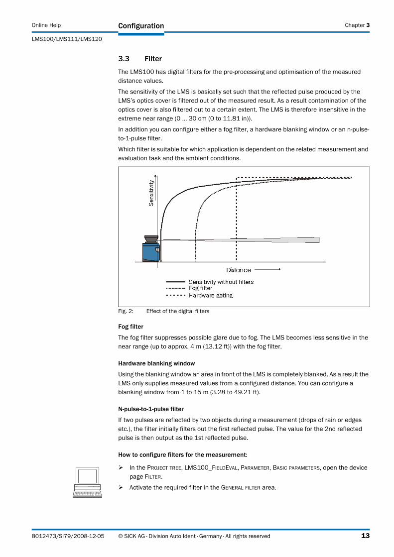
3.3 Filter
The LMS100 has digital filters for the pre-processing and optimisation of the measured distance values.
The sensitivity of the LMS is basically set such that the reflected pulse produced by the LMS’s optics cover is filtered out of the measured result. As a result contamination of the optics cover is also filtered out to a certain extent. The LMS is therefore insensitive in the extreme near range (0 … 30 cm (0 to 11.81 in)).
In addition you can configure either a fog filter, a hardware blanking window or an n-pulse-to-1-pulse filter.
Which filter is suitable for which application is dependent on the related measurement and evaluation task and the ambient conditions.
Fig. 2: Effect of the digital filters
Fog filter
The fog filter suppresses possible glare due to fog. The LMS becomes less sensitive in the near range (up to approx. 4 m (13.12 ft)) with the fog filter.
Hardware blanking window
Using the blanking window an area in front of the LMS is completely blanked. As a result the LMS only supplies measured values from a configured distance. You can configure a blanking window from 1 to 15 m (3.28 to 49.21 ft).
N-pulse-to-1-pulse filter
If two pulses are reflected by two objects during a measurement (drops of rain or edges etc.), the filter initially filters out the first reflected pulse. The value for the 2nd reflected pulse is then output as the 1st reflected pulse.
How to configure filters for the measurement:
� In the PROJECT TREE, LMS100_FIELDEVAL, PARAMETER, BASIC PARAMETERS, open the device page FILTER.
� Activate the required filter in the GENERAL FILTER area.
8012473/SI79/2008-12-05 © SICK AG · Division Auto Ident · Germany · All rights reserved 13
Chapter 3 Configuration Online Help
Laser measurement systems LMS100/LMS111/LMS120
3.3.1 Field evaluation filters
Field evaluation filters act on the field application, not on the measured value output.
Particle filter
The particle filter can be used in dusty surroundings or in case of rain or snow to filter out interference due to particles of dust, rain drops, snow flakes etc.
The filter compares each measured value with the measured value at the same angle in the previous scan and the measured values for the neighbouring angles in the previous scan.
If the difference between the measured value measured and the measured values used for the comparison exceeds a certain threshold, the measured value is evaluated as interference and is not taken into account.
How to configure filters for the field application:
3.3.2 Scan data output filter
Mean filter
The mean filter acts on the scan data output, not on the field application. With the mean filter active, you can configure the number of scans from which the mean is formed.
The mean filter reduces the scan data output (not a smoothing mean). If the mean from 10 scans is formed, scan data are only output after each 10th scan.
3.4 Increment source
The LMS can be used, e.g. on vehicles, or measurements can be made on moving objects, e.g. on a conveyor system. In these cases the velocity of the vehicle or the object can be configured or measured.
Evaluation fields can also be modified dynamically, e.g. to implement vehicle monitoring (see 3.5.7 on page 26) or the de-bounce times on the digital outputs can be controlled as a function of the track (see 3.8.9 on page 44).
To be able to use these functions, configure …
• the encoder type
• the increment source parameters
3.4.1 Encoder
The LMS can use the pulses from an encoder to determine the position or velocity.
You can use the following encoders:
• single-channel, is only connected to INC1,no direction detection
• Dual-channel, is connected to INC1 and INC2,the pulses have a phase offset of 90°, as a result direction detection is possible.
� Then enter the resolution of the encoder in mm/increment in the ENCODER RESOLUTION input field.
� In the PROJECT TREE, LMS100_FIELDEVAL, PARAMETER, BASIC PARAMETERS, open the device page FILTER.
� Activate the required filter in the FIELD EVALUATION FILTER area.
14 © SICK AG · Division Auto Ident · Germany · All rights reserved 8012473/SI79/2008-12-05
Online Help
LMS100/LMS111/LMS120
Configuration Chapter 3
How to configure the encoder type:
3.4.2 Increment
Select one of the following increment sources:
• constant velocityNo encoder is connected. The vehicle moves at constant speed. Enter this velocity in SOPAS ET.
• encoderThe pulses from an encoder connected to the inputs on the LMS. You can enter the resolution for this encoder in the configuration for the encoder (see 3.4.1 on page 14).
How to configure the increment source:
� In the PROJECT TREE, LMS100_FIELDEVAL, PARAMETER, open the device page INCREMENT CONFIGURATION.
� Choose in the ENCODER area in the ENCODER SETTINGS selection field the encoder connected and enter the necessary parameters.
� In the PROJECT TREE, LMS100_FIELDEVAL, PARAMETER, open the device page INCREMENT CONFIGURATION.
� Choose in the INCREMENT area in the INCREMENT SOURCE selection field the required source and enter the necessary parameters.
8012473/SI79/2008-12-05 © SICK AG · Division Auto Ident · Germany · All rights reserved 15
Chapter 3 Configuration Online Help
Laser measurement systems LMS100/LMS111/LMS120
3.5 Evaluation fields
With the aid of the field application integrated into the LMS100, up to ten evaluation fields can be configured. The existing evaluation cases are displayed in a table in the EVALUATION CASES OVERVIEW area.
The table shows along with the number and name of the related evaluation field, the evaluation case to which the evaluation field is linked.
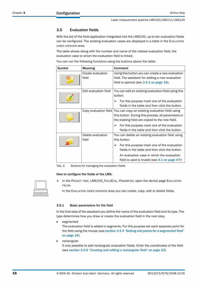
You can run the following functions using the buttons above the table:
How to configure the fields of the LMS:
3.5.1 Basic parameters for the field
In the first step of the assistant you define the name of the evaluation field and its type. The type determines how you draw or create the evaluation field in the next step.
• segmentedThe evaluation field is added in segments. For this purpose set each separate point for the field using the mouse (see section 3.5.4 “Setting end points for a segmented field” on page 19).
• rectangularIt only possible to add rectangular evaluation fields. Enter the coordinates of the field (see section 3.5.6 “Creating and editing a rectangular field” on page 23).
Symbol Meaning CommentCreate evaluation field
Using this button you can create a new evaluation field. The assistant for adding a new evaluation field is opened (see 3.5.1 on page 16).
Edit evaluation field You can edit an existing evaluation field using this button.
� For this purpose mark one of the evaluation fields in the table and then click the button.
Copy evaluation field You can copy an existing evaluation field using this button. During this process, all parameters in the existing field are copied to the new field.
� For this purpose mark one of the evaluation fields in the table and then click the button.
Delete evaluation field
You can delete an existing evaluation field using this button.
� For this purpose mark one of the evaluation fields in the table and then click the button.
An evaluation case in which the evaluation field is used is invalid (see 4.1 on page 47)!
Tab. 2: Buttons for managing the evaluation fields
� In the PROJECT TREE, LMS100_FIELDEVAL, PARAMETER, open the device page EVALUATION FIELDS.
In the EVALUATION CASES OVERVIEW area you can create, copy, edit or delete fields.
16 © SICK AG · Division Auto Ident · Germany · All rights reserved 8012473/SI79/2008-12-05
Online Help
LMS100/LMS111/LMS120
Configuration Chapter 3
• dynamicUsing dynamic fields you can realise speed-dependent fields, e.g. for vehicle monitoring. It only possible to add rectangular evaluation fields. For this purpose you enter the coordinates of the field, the minimum and the maximum physical size of a field (see section 3.5.7 “Creating and editing a dynamic field” on page 26).
3.5.2 Using the field editor
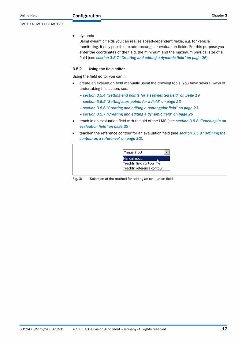
Using the field editor you can …
• create an evaluation field manually using the drawing tools. You have several ways of undertaking this action, see:
– section 3.5.4 “Setting end points for a segmented field” on page 19 – section 3.5.5 “Setting start points for a field” on page 23
– section 3.5.6 “Creating and editing a rectangular field” on page 23
– section 3.5.7 “Creating and editing a dynamic field” on page 26
• teach-in an evaluation field with the aid of the LMS (see section 3.5.8 “Teaching-in an evaluation field” on page 29).
• teach-in the reference contour for an evaluation field (see section 3.5.9 “Defining the contour as a reference” on page 32).
Fig. 3: Selection of the method for adding an evaluation field
8012473/SI79/2008-12-05 © SICK AG · Division Auto Ident · Germany · All rights reserved 17
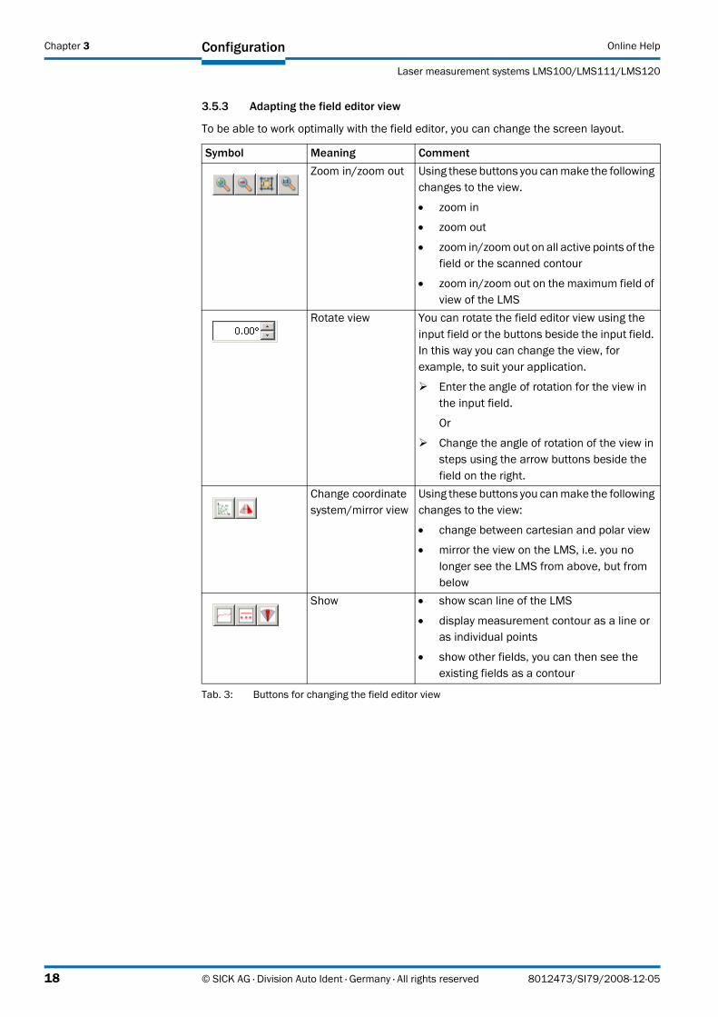
Chapter 3 Configuration Online Help
Laser measurement systems LMS100/LMS111/LMS120
3.5.3 Adapting the field editor view
To be able to work optimally with the field editor, you can change the screen layout.
Symbol Meaning CommentZoom in/zoom out Using these buttons you can make the following
changes to the view.
• zoom in
• zoom out
• zoom in/zoom out on all active points of the field or the scanned contour
• zoom in/zoom out on the maximum field of view of the LMS
Rotate view You can rotate the field editor view using the input field or the buttons beside the input field. In this way you can change the view, for example, to suit your application.
� Enter the angle of rotation for the view in the input field.
Or
� Change the angle of rotation of the view in steps using the arrow buttons beside the field on the right.
Change coordinate system/mirror view
Using these buttons you can make the following changes to the view:
• change between cartesian and polar view
• mirror the view on the LMS, i.e. you no longer see the LMS from above, but from below
Show • show scan line of the LMS
• display measurement contour as a line or as individual points
• show other fields, you can then see the existing fields as a contour
Tab. 3: Buttons for changing the field editor view
18 © SICK AG · Division Auto Ident · Germany · All rights reserved 8012473/SI79/2008-12-05
Online Help
LMS100/LMS111/LMS120
Configuration Chapter 3
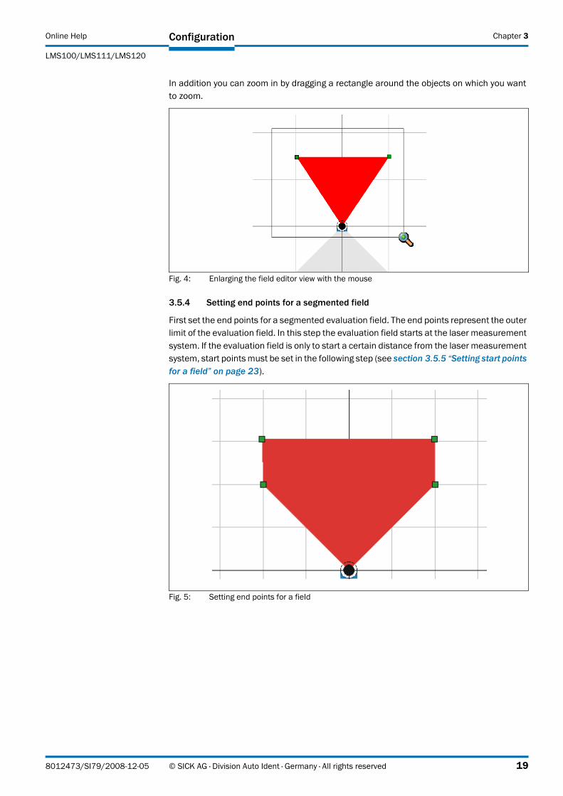
In addition you can zoom in by dragging a rectangle around the objects on which you want to zoom.
Fig. 4: Enlarging the field editor view with the mouse
3.5.4 Setting end points for a segmented field
First set the end points for a segmented evaluation field. The end points represent the outer limit of the evaluation field. In this step the evaluation field starts at the laser measurement system. If the evaluation field is only to start a certain distance from the laser measurement system, start points must be set in the following step (see section 3.5.5 “Setting start points for a field” on page 23).
Fig. 5: Setting end points for a field
8012473/SI79/2008-12-05 © SICK AG · Division Auto Ident · Germany · All rights reserved 19
Chapter 3 Configuration Online Help
Laser measurement systems LMS100/LMS111/LMS120
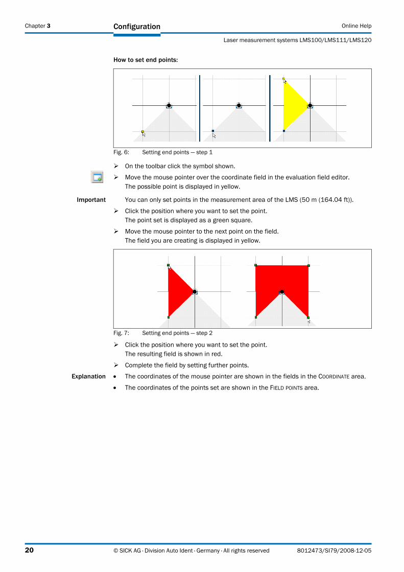
How to set end points:
Fig. 6: Setting end points — step 1
Important You can only set points in the measurement area of the LMS (50 m (164.04 ft)).
� Click the position where you want to set the point.The point set is displayed as a green square.
� Move the mouse pointer to the next point on the field.The field you are creating is displayed in yellow.
Fig. 7: Setting end points — step 2
� Click the position where you want to set the point.The resulting field is shown in red.
� Complete the field by setting further points.
Explanation • The coordinates of the mouse pointer are shown in the fields in the COORDINATE area.
• The coordinates of the points set are shown in the FIELD POINTS area.
� On the toolbar click the symbol shown.
� Move the mouse pointer over the coordinate field in the evaluation field editor. The possible point is displayed in yellow.
20 © SICK AG · Division Auto Ident · Germany · All rights reserved 8012473/SI79/2008-12-05
Online Help
LMS100/LMS111/LMS120
Configuration Chapter 3
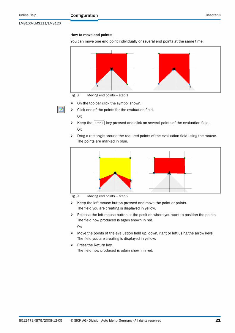
How to move end points:
You can move one end point individually or several end points at the same time.
Fig. 8: Moving end points — step 1
Fig. 9: Moving end points — step 2
� Keep the left mouse button pressed and move the point or points.The field you are creating is displayed in yellow.
� Release the left mouse button at the position where you want to position the points.The field now produced is again shown in red.
Or:
� Move the points of the evaluation field up, down, right or left using the arrow keys.The field you are creating is displayed in yellow.
� Press the Return key.The field now produced is again shown in red.
� On the toolbar click the symbol shown.
� Click one of the points for the evaluation field.
Or:
� Keep the [Ctrl] key pressed and click on several points of the evaluation field.
Or:
� Drag a rectangle around the required points of the evaluation field using the mouse.The points are marked in blue.
8012473/SI79/2008-12-05 © SICK AG · Division Auto Ident · Germany · All rights reserved 21
Chapter 3 Configuration Online Help
Laser measurement systems LMS100/LMS111/LMS120
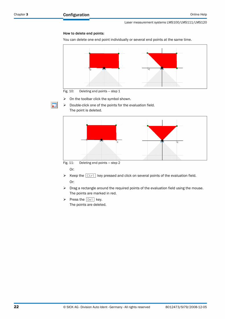
How to delete end points:
You can delete one end point individually or several end points at the same time.
Fig. 10: Deleting end points — step 1
Fig. 11: Deleting end points — step 2
Or:
� Keep the [Ctrl] key pressed and click on several points of the evaluation field.
Or:
� Drag a rectangle around the required points of the evaluation field using the mouse.The points are marked in red.
� Press the [Del] key.The points are deleted.
� On the toolbar click the symbol shown.
� Double-click one of the points for the evaluation field.The point is deleted.
22 © SICK AG · Division Auto Ident · Germany · All rights reserved 8012473/SI79/2008-12-05
Online Help
LMS100/LMS111/LMS120
Configuration Chapter 3
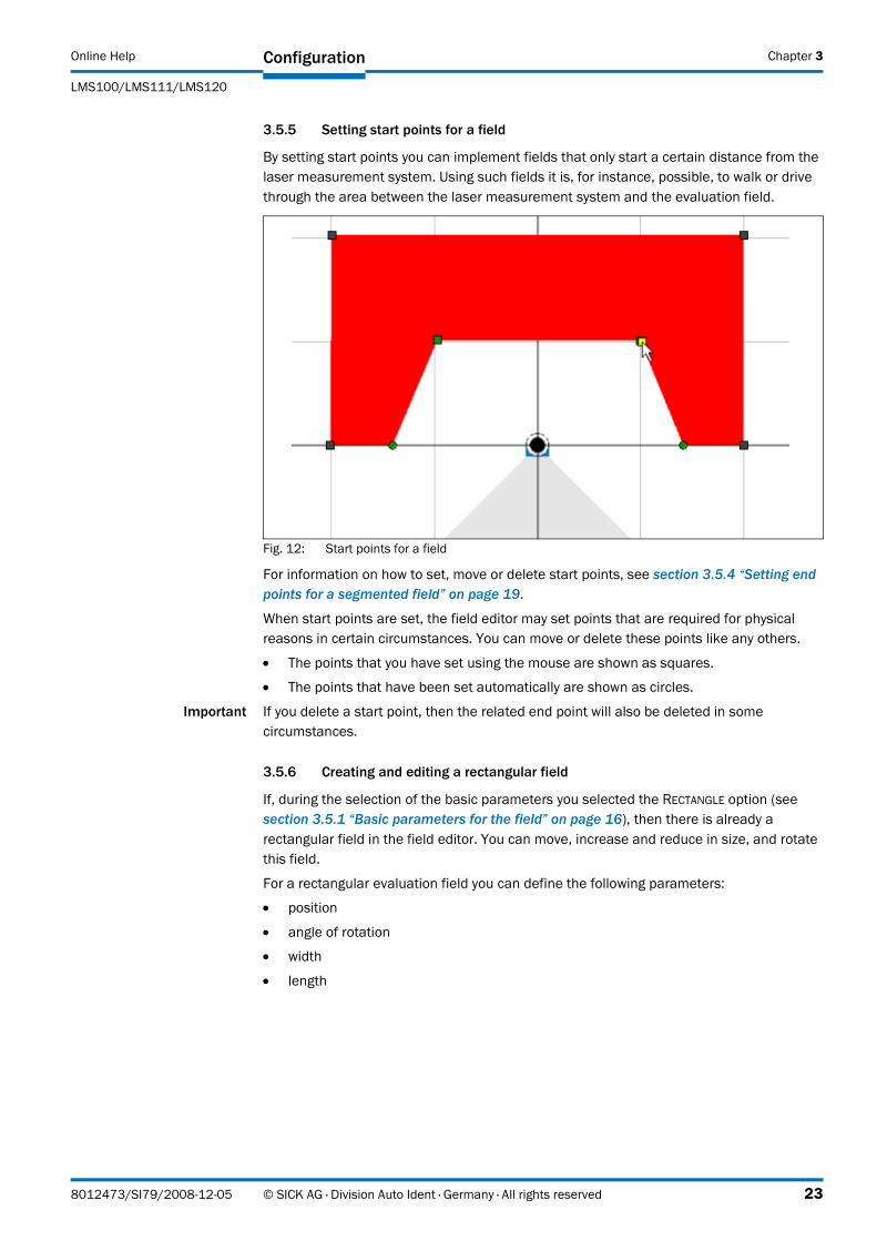
3.5.5 Setting start points for a field
By setting start points you can implement fields that only start a certain distance from the laser measurement system. Using such fields it is, for instance, possible, to walk or drive through the area between the laser measurement system and the evaluation field.
Fig. 12: Start points for a field
For information on how to set, move or delete start points, see section 3.5.4 “Setting end points for a segmented field” on page 19.
When start points are set, the field editor may set points that are required for physical reasons in certain circumstances. You can move or delete these points like any others.
• The points that you have set using the mouse are shown as squares.
• The points that have been set automatically are shown as circles.
Important If you delete a start point, then the related end point will also be deleted in some circumstances.
3.5.6 Creating and editing a rectangular field
If, during the selection of the basic parameters you selected the RECTANGLE option (see section 3.5.1 “Basic parameters for the field” on page 16), then there is already a rectangular field in the field editor. You can move, increase and reduce in size, and rotate this field.
For a rectangular evaluation field you can define the following parameters:
• position
• angle of rotation
• width
• length
8012473/SI79/2008-12-05 © SICK AG · Division Auto Ident · Germany · All rights reserved 23
Chapter 3 Configuration Online Help
Laser measurement systems LMS100/LMS111/LMS120
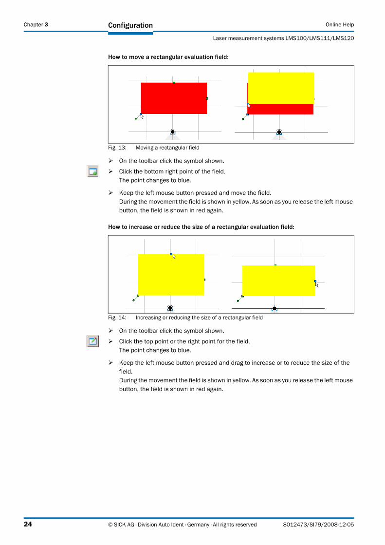
How to move a rectangular evaluation field:
Fig. 13: Moving a rectangular field
� Keep the left mouse button pressed and move the field.During the movement the field is shown in yellow. As soon as you release the left mouse button, the field is shown in red again.
How to increase or reduce the size of a rectangular evaluation field:
Fig. 14: Increasing or reducing the size of a rectangular field
� Keep the left mouse button pressed and drag to increase or to reduce the size of the field.During the movement the field is shown in yellow. As soon as you release the left mouse button, the field is shown in red again.
� On the toolbar click the symbol shown.
� Click the bottom right point of the field.The point changes to blue.
� On the toolbar click the symbol shown.
� Click the top point or the right point for the field.The point changes to blue.
24 © SICK AG · Division Auto Ident · Germany · All rights reserved 8012473/SI79/2008-12-05
Online Help
LMS100/LMS111/LMS120
Configuration Chapter 3
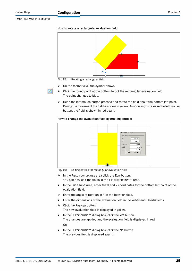
How to rotate a rectangular evaluation field:
Fig. 15: Rotating a rectangular field
� Keep the left mouse button pressed and rotate the field about the bottom left point.During the movement the field is shown in yellow. As soon as you release the left mouse button, the field is shown in red again.
How to change the evaluation field by making entries:
Fig. 16: Editing entries for rectangular evaluation field
� In the FIELD COORDINATES area click the EDIT button.You can now edit the fields in the FIELD COORDINATES area.
� In the BASE POINT area, enter the X and Y coordinates for the bottom left point of the evaluation field.
� Enter the angle of rotation in ° in the ROTATION field.
� Enter the dimensions of the evaluation field in the WIDTH and LENGTH fields.
� Click the PREVIEW button. The new evaluation field is displayed in yellow.
� In the CHECK CHANGES dialog box, click the YES button.The changes are applied and the evaluation field is displayed in red.
Or:
� In the CHECK CHANGES dialog box, click the NO button.The previous field is displayed again.
� On the toolbar click the symbol shown.
� Click the round point at the bottom left of the rectangular evaluation field.The point changes to blue.
8012473/SI79/2008-12-05 © SICK AG · Division Auto Ident · Germany · All rights reserved 25
Chapter 3 Configuration Online Help
Laser measurement systems LMS100/LMS111/LMS120
3.5.7 Creating and editing a dynamic field
If, during the selection of the basic parameters you selected the DYNAMIC option (see section 3.5.1 “Basic parameters for the field” on page 16), then there is already a dynamic field in the field editor. You can move this field and increase or reduce its size.
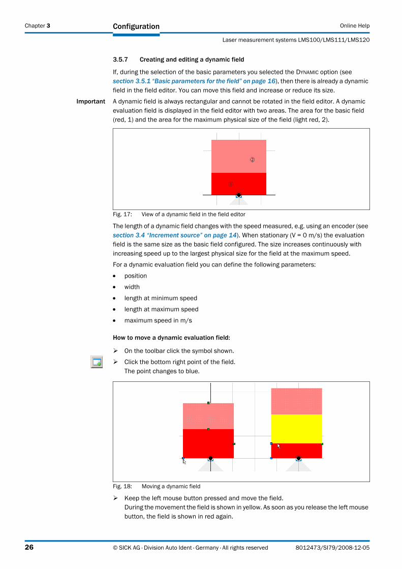
Important A dynamic field is always rectangular and cannot be rotated in the field editor. A dynamic evaluation field is displayed in the field editor with two areas. The area for the basic field (red, 1) and the area for the maximum physical size of the field (light red, 2).
Fig. 17: View of a dynamic field in the field editor
The length of a dynamic field changes with the speed measured, e.g. using an encoder (see section 3.4 “Increment source” on page 14). When stationary (V = 0 m/s) the evaluation field is the same size as the basic field configured. The size increases continuously with increasing speed up to the largest physical size for the field at the maximum speed.
For a dynamic evaluation field you can define the following parameters:
• position
• width
• length at minimum speed
• length at maximum speed
• maximum speed in m/s
How to move a dynamic evaluation field:
Fig. 18: Moving a dynamic field
� Keep the left mouse button pressed and move the field.During the movement the field is shown in yellow. As soon as you release the left mouse button, the field is shown in red again.
� On the toolbar click the symbol shown.
� Click the bottom right point of the field.The point changes to blue.
26 © SICK AG · Division Auto Ident · Germany · All rights reserved 8012473/SI79/2008-12-05
Online Help
LMS100/LMS111/LMS120
Configuration Chapter 3
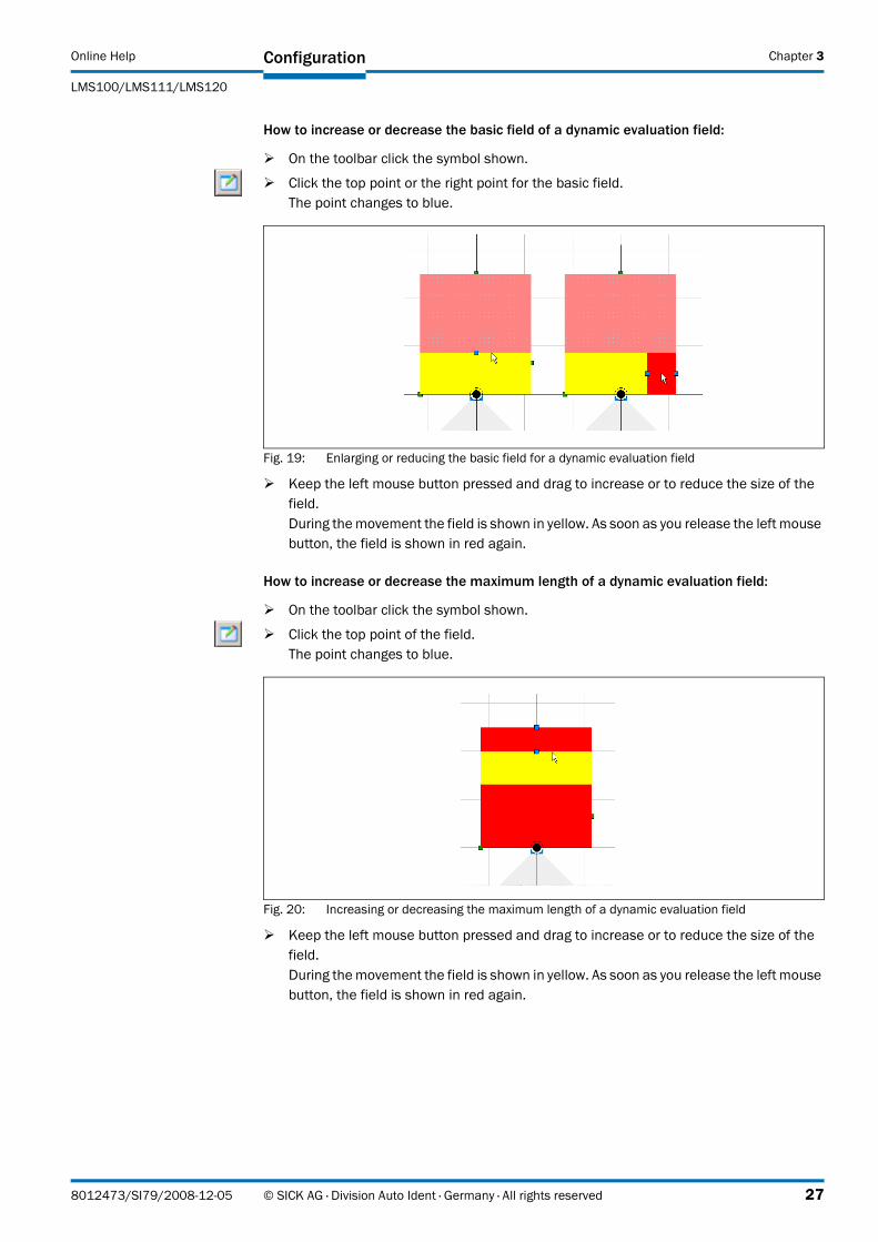
How to increase or decrease the basic field of a dynamic evaluation field:
Fig. 19: Enlarging or reducing the basic field for a dynamic evaluation field
� Keep the left mouse button pressed and drag to increase or to reduce the size of the field.During the movement the field is shown in yellow. As soon as you release the left mouse button, the field is shown in red again.
How to increase or decrease the maximum length of a dynamic evaluation field:
Fig. 20: Increasing or decreasing the maximum length of a dynamic evaluation field
� Keep the left mouse button pressed and drag to increase or to reduce the size of the field.During the movement the field is shown in yellow. As soon as you release the left mouse button, the field is shown in red again.
� On the toolbar click the symbol shown.
� Click the top point or the right point for the basic field.The point changes to blue.
� On the toolbar click the symbol shown.
� Click the top point of the field.The point changes to blue.
8012473/SI79/2008-12-05 © SICK AG · Division Auto Ident · Germany · All rights reserved 27
Chapter 3 Configuration Online Help
Laser measurement systems LMS100/LMS111/LMS120
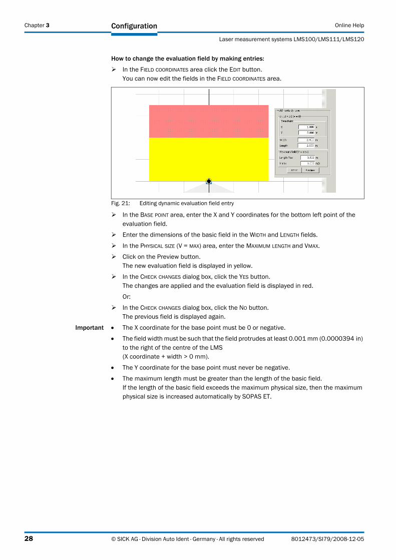
How to change the evaluation field by making entries:
� In the FIELD COORDINATES area click the EDIT button.You can now edit the fields in the FIELD COORDINATES area.
Fig. 21: Editing dynamic evaluation field entry
� In the BASE POINT area, enter the X and Y coordinates for the bottom left point of the evaluation field.
� Enter the dimensions of the basic field in the WIDTH and LENGTH fields.
� In the PHYSICAL SIZE (V = MAX) area, enter the MAXIMUM LENGTH and VMAX.
� Click on the Preview button. The new evaluation field is displayed in yellow.
� In the CHECK CHANGES dialog box, click the YES button.The changes are applied and the evaluation field is displayed in red.
Or:
� In the CHECK CHANGES dialog box, click the NO button.The previous field is displayed again.
Important • The X coordinate for the base point must be 0 or negative.
• The field width must be such that the field protrudes at least 0.001 mm (0.0000394 in) to the right of the centre of the LMS(X coordinate + width > 0 mm).
• The Y coordinate for the base point must never be negative.
• The maximum length must be greater than the length of the basic field. If the length of the basic field exceeds the maximum physical size, then the maximum physical size is increased automatically by SOPAS ET.
28 © SICK AG · Division Auto Ident · Germany · All rights reserved 8012473/SI79/2008-12-05
Online Help
LMS100/LMS111/LMS120
Configuration Chapter 3
3.5.8 Teaching-in an evaluation field
Important An evaluation field can only be taught-in if you have selected the SEGMENTED option in the basic parameters for the field.
The laser measurement system scans the visible room contour several times to teach-in an evaluation field. From the data obtained SOPAS ET determines the contour of the field.
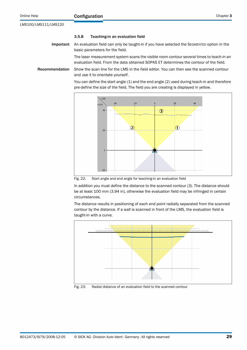
Recommendation Show the scan line for the LMS in the field editor. You can then see the scanned contour and use it to orientate yourself.
You can define the start angle (1) and the end angle (2) used during teach-in and therefore pre-define the size of the field. The field you are creating is displayed in yellow.
Fig. 22: Start angle and end angle for teaching-in an evaluation field
In addition you must define the distance to the scanned contour (3). The distance should be at least 100 mm (3.94 in), otherwise the evaluation field may be infringed in certain circumstances.
The distance results in positioning of each end point radially separated from the scanned contour by the distance. If a wall is scanned in front of the LMS, the evaluation field is taught-in with a curve.
Fig. 23: Radial distance of an evaluation field to the scanned contour
8012473/SI79/2008-12-05 © SICK AG · Division Auto Ident · Germany · All rights reserved 29
Chapter 3 Configuration Online Help
Laser measurement systems LMS100/LMS111/LMS120
How to teach-in an evaluation field:
� In the selection field on the top right in the field editor choose the TEACH-IN EVALUATION FIELD option.
The TEACH-IN EVALUATION FIELD dialog box is opened.
� Enter the values for the START ANGLE, END ANGLE and DISTANCE TO THE CONTOUR.
� Click the START button.
The contour will be scanned.
� Then, click the STOP button.
The evaluation field with its end points will be displayed.
Or:
� Walk along the field boundary required and during this process hold up a so-called target board (for example a piece of cardboard at least 10 × 10 cm) at the boundary required for the protective field.
SOPAS ET records the values for the objects scanned next. You can also define the size of the evaluation field by walking at a specific distance.
� Then, click the STOP button.
The evaluation field with its end points will be displayed.
Editing taught-in evaluation field
You can edit a taught-in evaluation field by moving or deleting the individual points for the field until the field has the required shape and size (see section “How to move end points:” on page 21 and section “How to delete end points:” on page 22).
This action is however limited by the fact that an end point is set for each angular step on teaching-in a field.
Important • Independent of the angular resolution configured, during teach-in points are taught-in at a spacing of 0.5°.
• You can only add points manually to a taught-in field if the angular resolution configured is 0.25° (see section 3.2.1 “Current configuration” on page 9).
• Points set manually are deleted by renewed teach-in.
30 © SICK AG · Division Auto Ident · Germany · All rights reserved 8012473/SI79/2008-12-05
Online Help
LMS100/LMS111/LMS120
Configuration Chapter 3
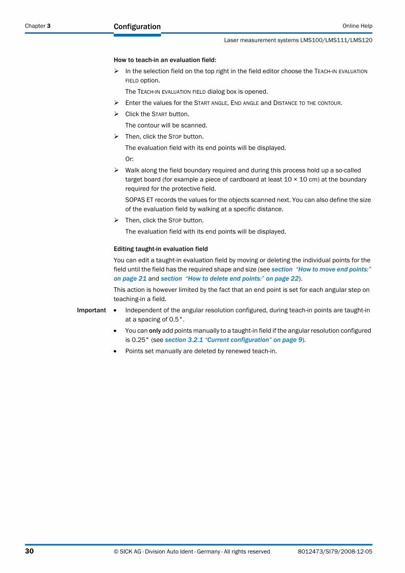
Defining start points for a taught-in evaluation field
In the next step of the assistant you can teach-in the start points for an evaluation field.
Important If you do not want to teach-in any start points, then click EXIT in the assistant. The evaluation field then reaches right up to the LMS.
A start point must be set for each end point. For this reason the same values for the start and end angle are pre-defined as for teaching-in the end points.
The distance to the scanned contour must be larger (2) when teaching-in the start points than when teaching-in the end points (1).
Fig. 24: Distance to the start points for a taught-in field
How to teach-in the start points of an evaluation field:
� In the selection field on the top right in the field editor choose the TEACH-IN EVALUATION FIELD option.
The TEACH-IN EVALUATION FIELD dialog box is opened.
� Enter the value for the DISTANCE TO THE CONTOUR.
The distance must be larger than when teaching-in the end points.
� Click the START button.
� Then, click the STOP button.
The evaluation field with its start points will be displayed.
8012473/SI79/2008-12-05 © SICK AG · Division Auto Ident · Germany · All rights reserved 31
Chapter 3 Configuration Online Help
Laser measurement systems LMS100/LMS111/LMS120
3.5.9 Defining the contour as a reference
With the contour as reference function an evaluation field is placed around the scanned contour of an object.
The actual function is activated by the strategy for the evaluation case. Evaluation case and evaluation field must therefore match (see section 3.6.4 “Evaluation strategy” on page 36).
For the evaluation of the field, the contour of an object (e.g. a house wall) must always be present inside the field, i.e. an object must always be present (the scanned contour is used as a reference).
You can either teach-in or set manually an evaluation field for the contour as reference.
Teaching-in evaluation field for contour as reference
Important An evaluation field can only be taught-in for the contour as reference function if you have selected the SEGMENTED option in the basic parameters for the field.
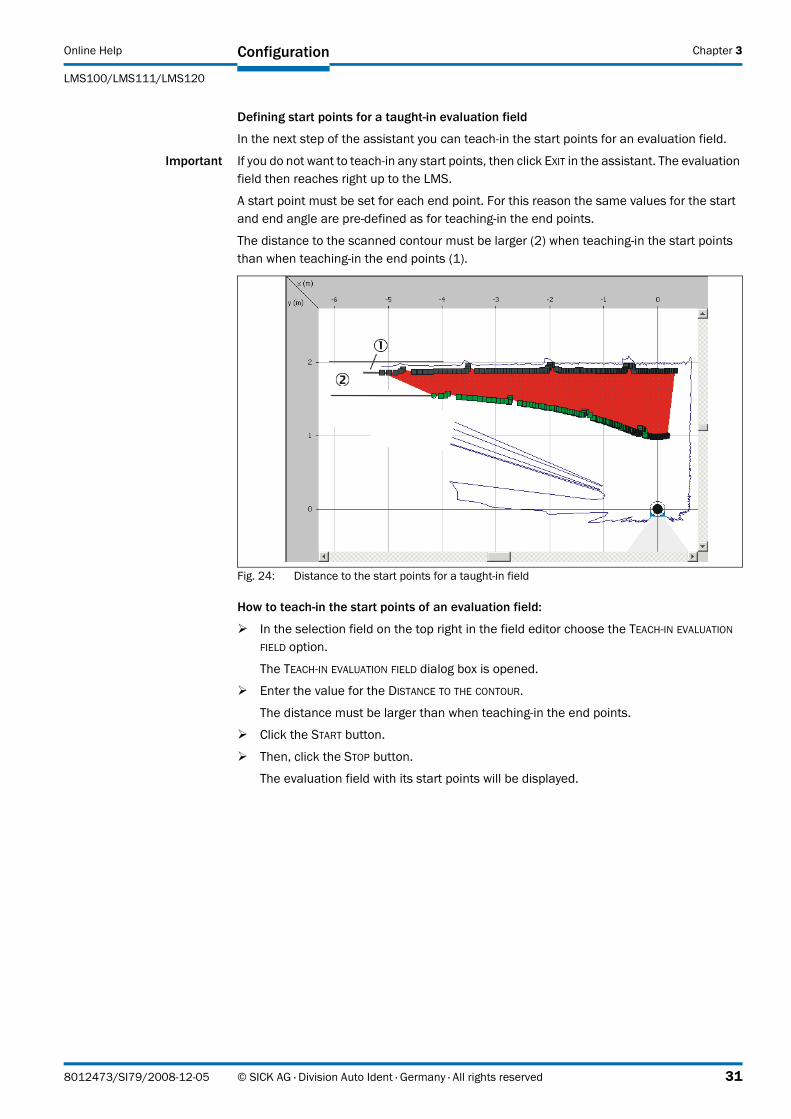
Recommendation Show the scan line for the LMS in the field editor. You can then see the scanned contour and use it to orientate yourself.
Fig. 25: Start angle and end angle during teach-in
You can define the start angle (1) and the end angle (2) used during teach-in and therefore pre-define the size of the field. The field you are creating is displayed in yellow.
32 © SICK AG · Division Auto Ident · Germany · All rights reserved 8012473/SI79/2008-12-05
Online Help
LMS100/LMS111/LMS120
Configuration Chapter 3
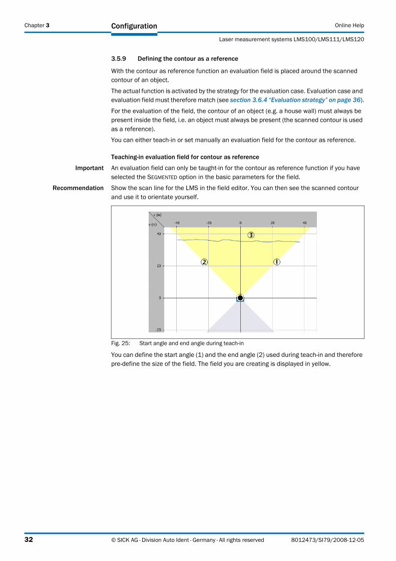
Fig. 26: Distance to the start points for a taught-in field
For the contour you must define the positive (2) and the negative (3) distance in relation to the scanned contour (1). The distance should be at least 100 mm (3.94 in), otherwise the contour will be continuously infringed.
How to teach-in an evaluation field for the contour as reference function:
� In the selection field on the top right in the field editor choose the TEACH-IN CONTOUR option.
The TEACH-IN CONTOUR dialog box is opened.
� Enter the values for START ANGLE and END ANGLE as well as for the POSITIVE DISTANCE and the NEGATIVE DISTANCE.
� Click the START button.
The contour will be scanned.
� Then, click the STOP button.
The evaluation field with its end points and start points is placed around the contour and displayed.
8012473/SI79/2008-12-05 © SICK AG · Division Auto Ident · Germany · All rights reserved 33
Chapter 3 Configuration Online Help
Laser measurement systems LMS100/LMS111/LMS120
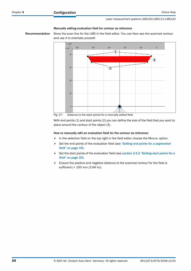
Manually editing evaluation field for contour as reference
Recommendation Show the scan line for the LMS in the field editor. You can then see the scanned contour and use it to orientate yourself.
Fig. 27: Distance to the start points for a manually edited field
With end points (1) and start points (2) you can define the size of the field that you want to place around the contour of the object (3).
How to manually edit an evaluation field for the contour as reference:
� In the selection field on the top right in the field editor choose the MANUAL option.
� Set the end points of the evaluation field (see “Setting end points for a segmented field” on page 19).
� Set the start points of the evaluation field (see section 3.5.5 “Setting start points for a field” on page 23).
� Ensure the positive and negative distance to the scanned contour for the field is sufficient (> 100 mm (3.94 in)).
34 © SICK AG · Division Auto Ident · Germany · All rights reserved 8012473/SI79/2008-12-05
Online Help
LMS100/LMS111/LMS120
Configuration Chapter 3
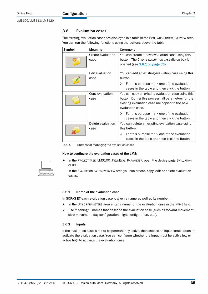
3.6 Evaluation cases
The existing evaluation cases are displayed in a table in the EVALUATION CASES OVERVIEW area. You can run the following functions using the buttons above the table:
How to configure the evaluation cases of the LMS:
3.6.1 Name of the evaluation case
In SOPAS ET each evaluation case is given a name as well as its number.
� In the BASIC PARAMETERS area enter a name for the evaluation case in the NAME field.
� Use meaningful names that describe the evaluation case (such as forward movement, slow movement, day configuration, night configuration, etc.).
3.6.2 Inputs
If the evaluation case is not to be permanently active, then choose an input combination to activate the evaluation case. You can configure whether the input must be active low or active high to activate the evaluation case.
Symbol Meaning CommentCreate evaluation case
You can create a new evaluation case using this button. The CREATE EVALUATION CASE dialog box is opened (see 3.6.1 on page 35).
Edit evaluation case
You can edit an existing evaluation case using this button.
� For this purpose mark one of the evaluation cases in the table and then click the button.
Copy evaluation case
You can copy an existing evaluation case using this button. During this process, all parameters for the existing evaluation case are copied to the new evaluation case.
� For this purpose mark one of the evaluation cases in the table and then click the button.
Delete evaluation case
You can delete an existing evaluation case using this button.
� For this purpose mark one of the evaluation cases in the table and then click the button.
Tab. 4: Buttons for managing the evaluation cases
� In the PROJECT TREE, LMS100_FIELDEVAL, PARAMETER, open the device page EVALUATION CASES.
In the EVALUATION CASES OVERVIEW area you can create, copy, edit or delete evaluation cases.
8012473/SI79/2008-12-05 © SICK AG · Division Auto Ident · Germany · All rights reserved 35
Chapter 3 Configuration Online Help
Laser measurement systems LMS100/LMS111/LMS120
You can also configure a combination of two input states to activate the evaluation case. As a result up to four combinations for activating different evaluations cases are possible.
Important • An input combination can also be defined for several evaluation cases, e.g. two evaluation cases will then be active simultaneously.
• If you choose NOT RELEVANT for both inputs, the evaluation case is always active.
� Choose whether and which input is to have the state active high or active low to activate the evaluation case.
3.6.3 Evaluation area
For each evaluation case, you can define which field is to be used. You can only select fields for an evaluation case if you have first created at least one field (see section 3.5 “Evaluation fields” on page 16).
Important If you have previously selected the contour evaluation strategy, then only segmented fields are available (rectangular and dynamic fields are hidden).
� In the FIELD NAME selection field choose the required evaluation field.The number of the evaluation field is displayed in the NUMBER field.
3.6.4 Evaluation strategy
The evaluation strategy defines how the evaluation field is evaluated.
Important The different strategies will produce different results. For this reason the evaluation strategy must exactly match the type of evaluation case.
Pixel evaluation
The LMS evaluates the entire area of the field. If an object enters the field, this result is sent to the related output.
For the LMS to detect an object, the object must be detected in one place for at least the duration of the RESPONSE TIME. The response time means that the presence of objects in the evaluation field will not immediately trigger the evaluation case. Objects must therefore be scanned several times if a response time is configured (for a scanning frequency of 25 Hz and a response time of 1,000 ms for example 25 times).
Input 1 Input 2 Evaluation caseActive high Active high Evaluation case 1Active high Active low Evaluation case 2Active low Active high Evaluation case 3Active low Active low Evaluation case 4
Tab. 5: Input combination examples
36 © SICK AG · Division Auto Ident · Germany · All rights reserved 8012473/SI79/2008-12-05
Online Help
LMS100/LMS111/LMS120
Configuration Chapter 3
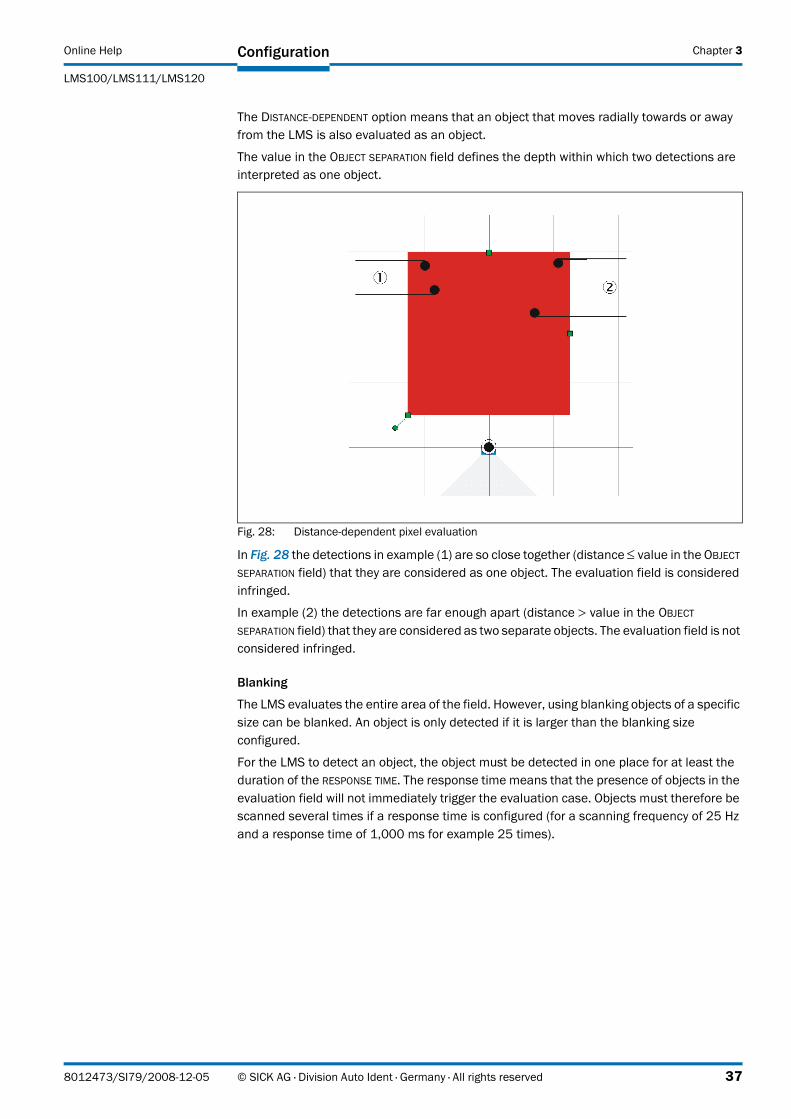
The DISTANCE-DEPENDENT option means that an object that moves radially towards or away from the LMS is also evaluated as an object.
The value in the OBJECT SEPARATION field defines the depth within which two detections are interpreted as one object.
Fig. 28: Distance-dependent pixel evaluation
In Fig. 28 the detections in example (1) are so close together (distance ≤ value in the OBJECT SEPARATION field) that they are considered as one object. The evaluation field is considered infringed.
In example (2) the detections are far enough apart (distance > value in the OBJECT SEPARATION field) that they are considered as two separate objects. The evaluation field is not considered infringed.
Blanking
The LMS evaluates the entire area of the field. However, using blanking objects of a specific size can be blanked. An object is only detected if it is larger than the blanking size configured.
For the LMS to detect an object, the object must be detected in one place for at least the duration of the RESPONSE TIME. The response time means that the presence of objects in the evaluation field will not immediately trigger the evaluation case. Objects must therefore be scanned several times if a response time is configured (for a scanning frequency of 25 Hz and a response time of 1,000 ms for example 25 times).
8012473/SI79/2008-12-05 © SICK AG · Division Auto Ident · Germany · All rights reserved 37
Chapter 3 Configuration Online Help
Laser measurement systems LMS100/LMS111/LMS120
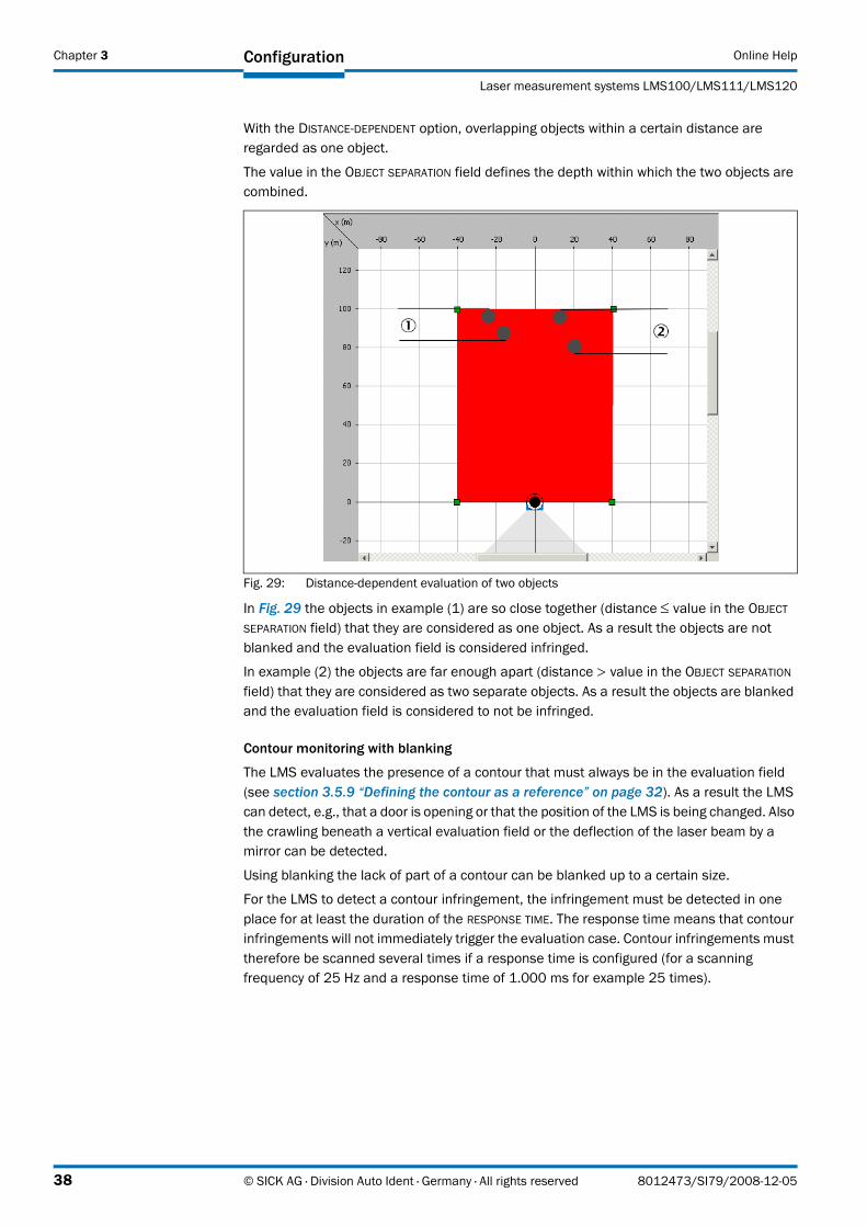
With the DISTANCE-DEPENDENT option, overlapping objects within a certain distance are regarded as one object.
The value in the OBJECT SEPARATION field defines the depth within which the two objects are combined.
Fig. 29: Distance-dependent evaluation of two objects
In Fig. 29 the objects in example (1) are so close together (distance ≤ value in the OBJECT SEPARATION field) that they are considered as one object. As a result the objects are not blanked and the evaluation field is considered infringed.
In example (2) the objects are far enough apart (distance > value in the OBJECT SEPARATION field) that they are considered as two separate objects. As a result the objects are blanked and the evaluation field is considered to not be infringed.
Contour monitoring with blanking
The LMS evaluates the presence of a contour that must always be in the evaluation field (see section 3.5.9 “Defining the contour as a reference” on page 32). As a result the LMS can detect, e.g., that a door is opening or that the position of the LMS is being changed. Also the crawling beneath a vertical evaluation field or the deflection of the laser beam by a mirror can be detected.
Using blanking the lack of part of a contour can be blanked up to a certain size.
For the LMS to detect a contour infringement, the infringement must be detected in one place for at least the duration of the RESPONSE TIME. The response time means that contour infringements will not immediately trigger the evaluation case. Contour infringements must therefore be scanned several times if a response time is configured (for a scanning frequency of 25 Hz and a response time of 1.000 ms for example 25 times).
38 © SICK AG · Division Auto Ident · Germany · All rights reserved 8012473/SI79/2008-12-05
Online Help
LMS100/LMS111/LMS120
Configuration Chapter 3
I/O operator
Using the I/O operator evaluation strategy you can link the inputs on the LMS with its outputs. The result of this operator depends on …
• whether the inputs are configured as active high or active low (see section 3.6.2 “Inputs” on page 35).
• which output the result of the evaluation acts upon and whether it is inverted (see section 3.6.5 “Evaluation result” on page 39).
• whether the output is switched by the field application (see section 3.8.9 “Digital outputs” on page 44).
• how the results of the monitoring cases are linked at the output (see section 3.8.10 “Digital outputs of the application” on page 44).
Manipulation prevention
If pixel evaluation is configured, glare may result in it no longer being possible for the LMS to monitor a field. If blanking is configured, small objects in the near range of the LMS can cause large shadows.
To prevent this situation arising, you can configure the TAMPER PROTECTION option. This feature switches the evaluation field if …
• an object that is smaller than or equal to the blanked object size is in front of the laser output aperture on the LMS for the configured EXPANDED RESPONSE TIME.
• if the LMS is dazzled for longer than the EXPANDED RESPONSE TIME configured.
3.6.5 Evaluation result
The used evaluation field and the evaluation strategy for the evaluation case produce an evaluation result as soon as the field is infringed or the contour is interrupted.
� Choose the physical output on which the result of the evaluation case is to act.
� Also choose whether the evaluation result is to be inverted.
� If necessary, enter a response time for the output.
Important Take into account this response time if you use a downstream system, e.g. for stopping a vehicle or plant. You must then, e.g., increase the stopping distance accordingly.
3.7 Data processing
In the OUTPUT FORMAT area you can configure which data are to be output in which format when the measured data are requested.
The measured data message contains two channels for the output of distance values and, if necessary, remission values.
The values for the first pulse received are transferred in channel 1, and the values for a 2nd pulse, if received, in channel 2. You can decide whether one of the channels or both of the channels are to be transferred.
Important If only one pulse is received, its values are always transferred in channel 1. If only channel 2 is activated, the measured value will be lost in such a case.
You can also configure whether remission values are to be transferred in addition to the distance values. For the remission values you can also decide whether the transfer is with a resolution of 8 bits (0 to 255) or 16 bits (0 to 65,535).
8012473/SI79/2008-12-05 © SICK AG · Division Auto Ident · Germany · All rights reserved 39
Chapter 3 Configuration Online Help
Laser measurement systems LMS100/LMS111/LMS120
In addition you can configure whether data from an incremental encoder connected, the device name configured for the LMS and a time stamp for the scan are output in the measured data message.
How to configure the data processing:
3.8 Network/interfaces/inputs and outputs
3.8.1 Network options
You must assign a device ID for the LMS. By default this ID is used as the CAN device number for the CAN bus (see 3.8.7 on page 43).
Important You must assign a unique device number from 1 to 127 for each device on the CAN bus.
In addition you can assign a device name. For example, use the device name to be able to identify the LMS more easily in a project with several devices.
How to configure the network options:
3.8.2 Monitoring
The LMS can monitor other devices over its interfaces. For this purpose a heartbeat message must be sent by these devices.
Choose the interface over which the other devices are to be monitored.
Enter the IDs for the devices to be monitored. Separate the IDs for several devices using commas (1,34,102).
Enter a maximum power up time for the monitored devices. This setting will result in the LMS only expecting the heartbeat message after this power time has elapsed. As a result there will not be any error messages during the power up time for the devices monitored.
How to configure the monitoring of the LMS:
� In the PROJECT TREE, LMS100_FIELDEVAL, PARAMETER, open the device page DATA PROCESSING.
� In the OUTPUT FORMAT area choose the necessary parameters.
� In the PROJECT TREE, LMS100_FIELDEVAL, PARAMETER, open the device page NETWORK/INTERFACES/IOS.
� In the NETWORK OPTIONS area, fill in the fields DEVICE ID and DEVICE NAME.
� In the PROJECT TREE, LMS100_FIELDEVAL, PARAMETER, open the device page NETWORK/INTERFACES/IOS.
� In the MONITORING area enter the necessary parameters.
40 © SICK AG · Division Auto Ident · Germany · All rights reserved 8012473/SI79/2008-12-05
Online Help
LMS100/LMS111/LMS120
Configuration Chapter 3
3.8.3 Serial host interface
The serial host interface is an RS-232 interface. The host interface permits the configuration of the LMS and only limited measured value output.
The factory setting for the host interface is as follows:
• 57,600 Baud
• 8 data bits
• 1 stop bit
• no parity
Important If you change the parameters for the host interface over the host interface, the connection to the device will be lost. You must then scan for the LMS again in SOPAS ET.
Heartbeat message
The heartbeat message enables the connected application to cyclically check the device status even if it is idle. The message is always output if it is not possible to measure an object.
� Activate the ENABLE HEARTBEAT MESSAGE option so that the LMS generates the related message.
� In the HEARTBEAT INTERVAL field enter the duration of the interval in seconds.
– If the RESTART THE INTERVAL ON SENDING option is activated, the interval is restarted immediately after sending. The time between two messages is exactly the duration of the interval in seconds.
– If the RESTART THE INTERVAL ON SENDING option is inactive, the interval is only restarted after the message has been sent successfully. The time between two messages is therefore longer than the duration of the interval in seconds.
How to configure the serial host interface:
3.8.4 Serial auxiliary interface
The serial auxiliary interface is an RS-232 interface. The auxiliary interface permits the configuration of the LMS.
The factory setting for the host interface is as follows:
• 57,600 Baud
• 8 data bits
• 1 stop bit
• no parity
Important If you change the parameters for the auxiliary interface over the auxiliary interface, the connection to the device will be lost. You must then scan for the LMS again in SOPAS ET.
Heartbeat message
The heartbeat message enables the connected application to cyclically check the device status even if it is idle. The message is always output if it is not possible to measure an object.
� In the PROJECT TREE, LMS100_FIELDEVAL, PARAMETER, NETWORK/INTERFACES/IOS, open the device page SERIAL.
� Make the necessary settings for the configuration in the SERIAL HOST INTERFACE area.
8012473/SI79/2008-12-05 © SICK AG · Division Auto Ident · Germany · All rights reserved 41
Chapter 3 Configuration Online Help
Laser measurement systems LMS100/LMS111/LMS120
� Activate the ENABLE HEARTBEAT MESSAGE option so that the LMS generates the related message.
� In the HEARTBEAT INTERVAL field enter the duration of the interval in seconds.
– If the RESTART THE INTERVAL ON SENDING option is activated, the interval is restarted immediately after sending. The time between two messages is exactly the duration of the interval in seconds.
– If the RESTART THE INTERVAL ON SENDING option is inactive, the interval is only restarted after the message has been sent successfully. The time between two messages is therefore longer than the duration of the interval in seconds.
How to configure the serial auxiliary interface:
3.8.5 General parameters for the Ethernet interface
The Ethernet interface has a data transmission rate of 10/100 MBit. The interface is a TCP/IP interface. Full duplex and half duplex are supported.
The RS-Ethernet interface allows the configuration of the LMS as well as the output of measured values.
Important If you change the parameters for the Ethernet interface, to apply the parameters you must first save the data in the LMS in non-volatile memory and then restart the LMS. The RESTART button is available for this action. If your PC/notebook is connected to the LMS using the Ethernet interface, the connection to the device will be lost. You must then scan for the LMS again in SOPAS ET.
How to configure the Ethernet interface:
3.8.6 Parameters for the host port and the aux ports for the Ethernet interface
The Ethernet interface has two ports, the host port and the aux port. You can configure the LMS and communicate with the LMS using messages over both ports.
As a result you can setup the interface as follows:
• The configuration and the message communication are realised using a common port.
• The configuration is realised using one port, the message communication via the other port.
Heartbeat message
The heartbeat message enables the connected application to cyclically check the device status even if it is idle. The message is always output if it is not possible to measure an object.
� Activate the ENABLE HEARTBEAT MESSAGE option so that the LMS generates the related message.
� In the PROJECT TREE, LMS100_FIELDEVAL, PARAMETER, NETWORK/INTERFACES/IOS, open the device page SERIAL.
� Make the necessary settings for the configuration in the SERIAL AUXILIARY INTERFACE area.
� In the PROJECT TREE, LMS100_FIELDEVAL, PARAMETER, NETWORK/INTERFACES/IOS, open the device page ETHERNET.
� In the ETHERNET area enter the necessary parameters for the operation of the Ethernet interface.
42 © SICK AG · Division Auto Ident · Germany · All rights reserved 8012473/SI79/2008-12-05
Online Help
LMS100/LMS111/LMS120
Configuration Chapter 3
� In the HEARTBEAT INTERVAL field enter the duration of the interval in seconds.
– If the RESTART THE INTERVAL ON SENDING option is activated, the interval is restarted immediately after sending. The time between two messages is exactly the duration of the interval in seconds.
– If the RESTART THE INTERVAL ON SENDING option is inactive, the interval is only restarted after the message has been sent successfully. The time between two messages is therefore longer than the duration of the interval in seconds.
3.8.7 CAN bus
Important The LMS supports the CAN standard 2.0A.
For data communication using CAN (Controller Area Network) you must …
• set the correct operating mode for the CAN bus on the LMS.
– SICK network (for communication with SICK devices via CAN)– CANopen (for communication with devices supporting the CANopen standard)
• set identical baud rate parameters on all devices on the bus.
In addition you must define a device ID between 1 and 127 that is unique on the CAN bus. The device ID for the LMS is entered by default (see section 3.8.1 “Network options” on page 40).
Deactivate the USE DEVICE ID AS CAN ID option. Then a CAN ID that is different to the device ID can be entered in the CAN ID field.
How to configure the CAN interface:
3.8.8 Digital inputs
Im CONTROL field choose whether you want to set the de-bounce as a function of time or track.
• In case of time-dependent control, enter the debounce in ms.
• In case of track-dependent control, enter the debounce in mm.
Important For track-dependent control an encoder must be connected and configured. The LMS can then calculate a distance based on the encoder pulses (e.g. for a vehicle). The de-bounce can be defined as a function of a distance, speed fluctuations have no effect.
Logic
For switches or sensors connected to the inputs, choose whether these are to be active high or active low.
� In the PROJECT TREE, LMS100_FIELDEVAL, PARAMETER, NETWORK/INTERFACES/IOS, open the device page CAN.
� In the CAN area in the MODE and BAUD RATE fields enter the valid values for the CAN bus.
8012473/SI79/2008-12-05 © SICK AG · Division Auto Ident · Germany · All rights reserved 43
Chapter 3 Configuration Online Help
Laser measurement systems LMS100/LMS111/LMS120
Debounce
To bridge bounce times on external switches, you can configure a debounce for the inputs.
� In the DEBOUNCE input field enter the time in ms that is necessary to debounce the switches or sensors connected.
Or
� In the DEBOUNCE input field enter the track in mm that is necessary to debounce the switches or sensors connected.
3.8.9 Digital outputs
For the output 1 to output 3 outputs on the LMS, first choose the function that the output is to perform.
• no function
• applicationThe output is available for the field application. Infringements of the evaluation fields or contour infringements are signalled by the output.
• Device ReadyThe output is used to signal the status "Device Ready".The output is maintained for at least 200 ms.
• SOPAS commandThe output is controlled using messages from a host (see chapter "Annex" in the operating instructions for the LMS).
For the outputs you can select whether they are to switch active high or active low.
How to configure the function of the outputs:
3.8.10 Digital outputs of the application
If several monitoring cases act on an output, you must define how the results of the monitoring cases are linked. The related results can be linked using an AND or an OR operator.
Explanation The LOGIC selection field in only active if you have configured at least two evaluation cases that act on the output (see section 3.6.1 “Name of the evaluation case” on page 35).
By default the related output is reset immediately.
However, you can configure a delay (e.g. to activate a horn or to forward the signal to a PLC) or reset the output using an input.
� In the RESET field select the option TIME. Configure in the RETENTION TIME field a time in ms for which the output remains in this active output state. Adjust the retention time to the input electronics on the downstream system.
Or
� In the RESET field select the option INPUT. In the NUMBER field choose the number of the input that is to reset the output. In the SENSITIVITY field choose what the input is to react to.
� In the PROJECT TREE, LMS100_FIELDEVAL, PARAMETER, NETWORK/INTERFACES/IOS, open the device page DIGITAL OUTPUTS.
In the OUTPUT 1…3 areas you can undertake the necessary configuration steps for the outputs.
44 © SICK AG · Division Auto Ident · Germany · All rights reserved 8012473/SI79/2008-12-05
Online Help
LMS100/LMS111/LMS120
Configuration Chapter 3
How to configure the function of the outputs:
3.8.11 External switching outputs
A CAN module can be supplied to expand the switching outputs. With this module additional external switching outputs are made available.
The external switching outputs have the same functionality as the digital switching outputs on the LMS (see section 3.8.9 “Digital outputs” on page 44 and section 3.8.10 “Digital outputs of the application” on page 44).
You can define whether the module is active. If you activate the module, the external outputs 1 to n are available for the evaluation cases.
You can also define which ID the module has on the CAN bus. For information on the ID and configuration of the module, see the operating instructions for the CAN module.
If you activate the MONITORING option, the external CAN module will be monitored via CAN bus. Only if the CAN module is functioning error-free, the LMS will change to the "Device Ready" status.
How to configure the function of the outputs:
Important If you deactivate the CAN module in SOPAS and have used the external switching outputs for evaluation cases (see section 3.6.5 “Evaluation result” on page 39), these evaluation cases will be invalid.
� In the PROJECT TREE, LMS100_FIELDEVAL, PARAMETER, NETWORK/INTERFACES/IOS, open the device page DIGITAL OUTPUTS.
In the OUTPUT 1…3 APPLICATION areas you can undertake the necessary configuration steps for the outputs.
� In the PROJECT TREE, LMS100_FIELDEVAL, PARAMETER, NETWORK/INTERFACES/IOS, open the device page EXTERNAL DIGITAL OUTPUTS.
� Select the option ACTIVE.
The EXTERNAL OUTPUT 1…N APPLICATION areas are displayed. You can undertake the necessary configuration steps for the outputs in these areas.
8012473/SI79/2008-12-05 © SICK AG · Division Auto Ident · Germany · All rights reserved 45
Chapter 3 Configuration Online Help
Laser measurement systems LMS100/LMS111/LMS120
3.8.12 Display
In SOPAS ET you can define which functions the LEDs and the 7-segment display are to have.
LED Q1 and Q2
• no functionThe two LEDs never illuminate.
• applicationThe two LEDs are controlled by the field application.
– Q1 illuminates if an evaluation field is infringed or a reference contour is interrupted.– Q2 never illuminates.
• SOPAS commandThe LEDs are controlled by a SOPAS ET message (see chapter "Annex" in the operating instructions for the LMS).
LED OK and Stop
• applicationThe two LEDs are controlled by the field application.
– OK illuminates if no evaluation field is infringed and no reference contour is interrupted.
– Stop illuminates if an evaluation field is infringed or a reference contour is interrupted.
• SOPAS commandThe LEDs are controlled by a SOPAS ET message (see chapter "Annex" in the operating instructions for the LMS).
7-segment display
• no functionThe 7-segment display never indicates anything.
• applicationThe 7-segment display is controlled by the field application and indicates the status and error messages from the LMS (see section "Troubleshooting" in the operating instructions for the LMS).
• SOPAS commandThe 7-segment display is controlled by a SOPAS ET message (see chapter "Annex" in the operating instructions for the LMS).
� In the PROJECT TREE, LMS100_FIELDEVAL, PARAMETER, NETWORK/INTERFACES/IOS, open the device page DISPLAY.
In the DISPLAY area you can undertake the necessary configuration steps for the LEDs and the 7-segment display.
46 © SICK AG · Division Auto Ident · Germany · All rights reserved 8012473/SI79/2008-12-05
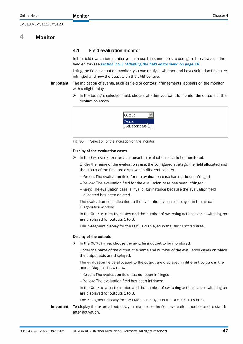
Online Help
LMS100/LMS111/LMS120
Monitor Chapter 4
4 Monitor
4.1 Field evaluation monitor
In the field evaluation monitor you can use the same tools to configure the view as in the field editor (see section 3.5.3 “Adapting the field editor view” on page 18).
Using the field evaluation monitor, you can analyse whether and how evaluation fields are infringed and how the outputs on the LMS behave.
Important The indication of events, such as field or contour infringements, appears on the monitor with a slight delay.
� In the top right selection field, choose whether you want to monitor the outputs or the evaluation cases.
Fig. 30: Selection of the indication on the monitor
Display of the evaluation cases
� In the EVALUATION CASE area, choose the evaluation case to be monitored.
Under the name of the evaluation case, the configured strategy, the field allocated and the status of the field are displayed in different colours.
– Green: The evaluation field for the evaluation case has not been infringed.– Yellow: The evaluation field for the evaluation case has been infringed.– Grey: The evaluation case is invalid, for instance because the evaluation field
allocated has been deleted.
The evaluation field allocated to the evaluation case is displayed in the actual Diagnostics window.
In the OUTPUTS area the states and the number of switching actions since switching on are displayed for outputs 1 to 3.
The 7-segment display for the LMS is displayed in the DEVICE STATUS area.
Display of the outputs
� In the OUTPUT area, choose the switching output to be monitored.
Under the name of the output, the name and number of the evaluation cases on which the output acts are displayed.
The evaluation fields allocated to the output are displayed in different colours in the actual Diagnostics window.
– Green: The evaluation field has not been infringed.– Yellow: The evaluation field has been infringed.
In the OUTPUTS area the states and the number of switching actions since switching on are displayed for outputs 1 to 3.
The 7-segment display for the LMS is displayed in the DEVICE STATUS area.
Important To display the external outputs, you must close the field evaluation monitor and re-start it after activation.
8012473/SI79/2008-12-05 © SICK AG · Division Auto Ident · Germany · All rights reserved 47
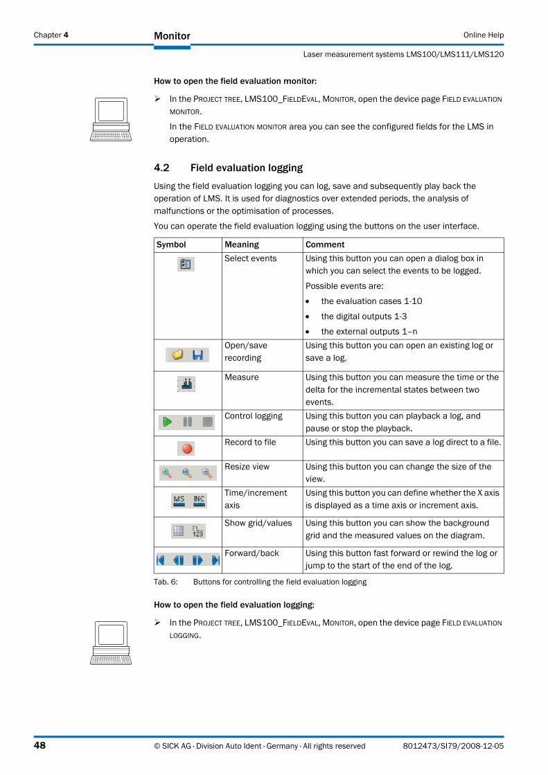
Chapter 4 Monitor Online Help
Laser measurement systems LMS100/LMS111/LMS120
How to open the field evaluation monitor:
4.2 Field evaluation logging
Using the field evaluation logging you can log, save and subsequently play back the operation of LMS. It is used for diagnostics over extended periods, the analysis of malfunctions or the optimisation of processes.
You can operate the field evaluation logging using the buttons on the user interface.
How to open the field evaluation logging:
� In the PROJECT TREE, LMS100_FIELDEVAL, MONITOR, open the device page FIELD EVALUATION MONITOR.
In the FIELD EVALUATION MONITOR area you can see the configured fields for the LMS in operation.
Symbol Meaning CommentSelect events Using this button you can open a dialog box in
which you can select the events to be logged.
Possible events are:
• the evaluation cases 1-10
• the digital outputs 1-3
• the external outputs 1–nOpen/save recording
Using this button you can open an existing log or save a log.
Measure Using this button you can measure the time or the delta for the incremental states between two events.
Control logging Using this button you can playback a log, and pause or stop the playback.
Record to file Using this button you can save a log direct to a file.
Resize view Using this button you can change the size of the view.
Time/increment axis
Using this button you can define whether the X axis is displayed as a time axis or increment axis.
Show grid/values Using this button you can show the background grid and the measured values on the diagram.
Forward/back Using this button fast forward or rewind the log or jump to the start of the end of the log.
Tab. 6: Buttons for controlling the field evaluation logging
� In the PROJECT TREE, LMS100_FIELDEVAL, MONITOR, open the device page FIELD EVALUATION LOGGING.
48 © SICK AG · Division Auto Ident · Germany · All rights reserved 8012473/SI79/2008-12-05
Online Help
LMS100/LMS111/LMS120
Service/system status Chapter 5
5 Service/system status
5.1 LMS status
The CURRENT STATUS field shows the current device status.
• undefined = the device is not online
• idle
• set speed
• stand by
• measurement active
With the aid of the TARGET STATUS indication you can see which device status will be achieved.
If, for instance, on an LMS at idle you start the measurement (see section 3.2.3 “Measurement” on page 12), then the target status immediately changes to "Measurement active". The motor must first reach the set speed, the current status will only change after a delay.
The CURRENT TEMPERATURE field also indicates the operating temperature in °C.
The DEVICE field shows whether the LMS100 is ready ("Device Ready" status) or not.
How to display the LMS status:
5.2 Contamination
The LMS determines the amount of contamination on the optics cover using internal tests. The STATE field shows the current device status.
• not contaminated = optics cover clean (or device not online)
• contamination warning = device still ready for operation, optics cover should be cleaned
• contamination error = device not ready for operation, optics cover must be cleaned
How to display the contamination measurement:
Cease operation if the cause of the malfunction has not been clearly identified!
Stop the machine/system if you cannot clearly identify or allocate the error and if you cannot safely rectify the malfunction.
� In the PROJECT TREE, LMS100_FIELDEVAL, SERVICE, open the device page SYSTEM STATUS.
If the device is connected and switched online, information is displayed in the LMS STATUS area on the LMS status, the status of the temperature range and the operating temperature of the LMS.
� In the PROJECT TREE, LMS100_FIELDEVAL, SERVICE, open the device page SYSTEM STATUS.
In the CONTAMINATION area the contamination status is displayed if a device is connected and online.
8012473/SI79/2008-12-05 © SICK AG · Division Auto Ident · Germany · All rights reserved 49
Chapter 5 Service/system status Online Help
Laser measurement systems LMS100/LMS111/LMS120
5.3 Encoder status
In the ENCODER STATUS area the CURRENT SPEED is displayed if an encoder is connected. In addition the CURRENT DIRECTION OF ROTATION is displayed.
• upward = positive direction of rotation (the increment count increases)
• downward = negative direction of rotation (the increment count decreases)
How to display the encoder status:
5.4 Operating data
5.4.1 Device information
In the DEVICE INFORMATION area you will find, with the device online, the MANUFACTURER, DEVICE TYPE, SOFTWARE VERSION, ORDER NUMBER and SERIAL NUMBER for the LMS. Keep this information at hand if, for example, you have questions for SICK support.
How to display the device information:
5.4.2 Operating data
In the OPERATING DATA area in the POWER-ON COUNTER read-only field the number of times the device has been switched on since initial commissioning is displayed.
In the OPERATING HOURS field the total number of operating hours since the initial commissioning of the device is displayed.
In the DAILY OPERATING HOURS field the number of operating hours the device has been running since the last power on is displayed.
How to display the operating data:
5.4.3 Service information
In the SERVICE INFORMATION area you will find, with the device switched online, information on service and configuration:
The name of the user account entered in Windows for configuration is displayed in the LAST USER NAME field.
The date of the last configuration is displayed in the LAST CONFIGURATION field.
� In the PROJECT TREE, LMS100_FIELDEVAL, SERVICE, open the device page SYSTEM STATUS.In the ENCODER STATUS area the CURRENT SPEED and the CURRENT DIRECTION OF ROTATION are displayed.
� In the PROJECT TREE, LMS100_FIELDEVAL, SERVICE, open the device page OPERATING DATA.
In the DEVICE INFORMATION area when the device is online you will see information on the LMS.
� In the PROJECT TREE, LMS100_FIELDEVAL, SERVICE, open the device page OPERATING DATA.
In the OPERATING DATA area when the device is online you will see the operating data of the LMS.
50 © SICK AG · Division Auto Ident · Germany · All rights reserved 8012473/SI79/2008-12-05
Online Help
LMS100/LMS111/LMS120
Service/system status Chapter 5
You can enter the date of the last maintenance performed in the LAST MAINTENANCE field.
You can enter the date of the next maintenance in the NEXT MAINTENANCE field.
How to display the service information:
� In the PROJECT TREE, LMS100_FIELDEVAL, SERVICE, open the device page OPERATING DATA.
In the SERVICE INFORMATION area when the device is online you will see service information on the LMS.
8012473/SI79/2008-12-05 © SICK AG · Division Auto Ident · Germany · All rights reserved 51
Chapter 6 Glossary Online Help
Laser measurement systems LMS100/LMS111/LMS120
6 Glossary
Note For other terms, see also the online help for the SOPAS ET configuration software.
Auxiliary interface
Auxiliary interface (RS-232) on the LMS with fixed measured data output format. Using this interface it is always possible to access the LMS using the SOPAS ET configuration software. Is used, among other tasks, for the output of system messages and error messages. Can be used with various functions.
Download
Transmission of the parameter set that has been modified offline in the SOPAS ET configuration software from the PC to the LMS. SOPAS ET transmits either always a complete copy to the memory (RAM) of the LMS (menu COMMUNICATION, DOWNLOAD ALL PARAMETERS TO DEVICE) or only the parameter that has just been edited with the aid of the context menu opened using the right mouse button (menu COMMUNICATION, DOWNLOAD MODIFIED PARAMETERS TO DEVICE). With the menu LMS_FIELDEVAL, PARAMETER, SAVE PERMANENT,the parameter set is saved permanently in the EEPROM of the LMS.
Line scanner
Scanner that very rapidly deflects its focused laser beam with the aid of a polygon mirror wheel with mirrors parallel to the axis. In this way the scanner generates a dot of light in the measuring plane that repeatedly runs along a straight line and appears to be a "stationary" scan line due to the relative slow response of the human eye.
Parameter set
Data set using which the functions implemented in the LMS are initialised and activated. Is transmitted from the LMS to SOPAS ET and in the reverse direction using UPLOAD or DOWNLOAD respectively.
SOPAS ET
Configuration software, can be used with Windows 2000/XP/Vista. Is used for the offline configuration (adaptation to the read situation on-site) and the online operation of the LMS in the dialog box.
SOPAS ET setup help
Online help that supports the usage of the SOPAS ET configuration software. The functions of the parameters for the LMS are explained in the help and the related value ranges are given. Can be used with an HTML browser, e.g. Internet Explorer and can be opened from SOPAS ET setup.
Upload
Transmission of the parameter set from the LMS to the PC into the SOPAS ET configuration software. The values for the parameters are displayed on the file cards of the configuration software. Prerequisite for the modification of the current parameter set.
52 © SICK AG · Division Auto Ident · Germany · All rights reserved 8012473/SI79/2008-12-05
Online Help
LMS100/LMS111/LMS120
Index Chapter 7
7 Index
Numerics
7-segment display ................................................................................................................... 46
A
Abbreviations ..............................................................................................................................4
Activation of an evaluation case ............................................................................................ 36
Angular resolution ...............................................................................................................9, 10
Auxiliary interface .................................................................................................................... 41
Available................................................................................................................................... 12
B
Baud rate ................................................................................................................................. 43
Blanking ................................................................................................................................... 37
Blanking window...................................................................................................................... 13
C
CAN........................................................................................................................................... 43
CAN baud rate.......................................................................................................................... 43
CAN device number................................................................................................................. 40
CAN ID ...................................................................................................................................... 40
CAN operating mode ............................................................................................................... 43
Configuration ..............................................................................................................................8
Configuration date................................................................................................................... 50
Contamination ......................................................................................................................... 49
Contamination measurement................................................................................................. 12
Contour as reference .............................................................................................................. 32
Contour monitoring with blanking .......................................................................................... 38
D
Data recording ......................................................................................................................... 48
Debounce................................................................................................................................. 44
Device ID .................................................................................................................................. 40
Device information .................................................................................................................. 50
Device name ............................................................................................................................ 40
Device Ready ........................................................................................................................... 44
Device type............................................................................................................................... 50
Dynamic field ........................................................................................................................... 26
8012473/SI79/2008-12-05 © SICK AG · Division Auto Ident · Germany · All rights reserved 53
Chapter 7 Index Online Help
Laser measurement systems LMS100/LMS111/LMS120
E
Ethernet interface ....................................................................................................................42
Evaluation cases ......................................................................................................................35
Evaluation field
Dynamic.........................................................................................................................17Rectangular...................................................................................................................16Segmented....................................................................................................................16Teach-in .........................................................................................................................29
Evaluation fields.......................................................................................................................16
Evaluation strategy ..................................................................................................................36
Expanded response time.........................................................................................................39
External switching outputs ......................................................................................................45
F
Field editor view .......................................................................................................................18
Field evaluation logging ...........................................................................................................48
Filter ..........................................................................................................................................13
Fog filter ....................................................................................................................................13
G
Glare..........................................................................................................................................39
H
Heartbeat message ..........................................................................................................41, 42
Highly available ........................................................................................................................12
Host interface...........................................................................................................................41
I
I/O operator ..............................................................................................................................39
Increment source .....................................................................................................................14
Inputs .................................................................................................................................35, 43
L
LEDs ..........................................................................................................................................45
Logging of the field evaluation ................................................................................................48
M
Maintenance date....................................................................................................................50
Manipulation prevention .........................................................................................................39
Mean filter ................................................................................................................................14
Monitor......................................................................................................................................47
Monitoring devices...................................................................................................................40
N
N-pulse-to-1-pulse filter ...........................................................................................................13
54 © SICK AG · Division Auto Ident · Germany · All rights reserved 8012473/SI79/2008-12-05
Online Help
LMS100/LMS111/LMS120
Index Chapter 7
O
Operating data ......................................................................................................................... 50
Operating hours ....................................................................................................................... 50
Operating mode ....................................................................................................................... 43
Output format .......................................................................................................................... 39
Outputs..................................................................................................................................... 44
P
Password.....................................................................................................................................8
Pixel evaluation........................................................................................................................ 36
R
Rectangular field ..................................................................................................................... 23
Reference................................................................................................................................. 32
Resetting configuration..............................................................................................................8
Response time with blanking ................................................................................................. 37
Response time with contour monitoring................................................................................ 38
Response time with pixel evaluation ..................................................................................... 36
S
Save as PDF................................................................................................................................8
Save configuration permanently ............................................................................................ 52
Save parameters ........................................................................................................................8
Save parameters permanently ............................................................................................... 52
Scanning frequency.............................................................................................................9, 10
Sensitive................................................................................................................................... 12
Serial number for the device .................................................................................................. 50
Setting end points ................................................................................................................... 19
Setting start points .................................................................................................................. 23
Shading .................................................................................................................................... 39
Software version.........................................................................................................................2
Starting angle........................................................................................................................... 11
Status ....................................................................................................................................... 49
Stopping angle......................................................................................................................... 11
Switching outputs .................................................................................................................... 44
Switching outputs external, outputs external ........................................................................ 45
8012473/SI79/2008-12-05 © SICK AG · Division Auto Ident · Germany · All rights reserved 55

8012
473/
SI79
/200
8-12
-05
∙ RV
<PM
6.5/
FM5.
5/PD
F>/X
X ∙ P
rinte
d in
Ger
man
y (2
008-
12) ∙
Sub
ject
to c
hang
e w
ithou
t not
ice
∙ The
spe
cifie
d pr
oduc
t fea
ture
s an
d te
chni
cal d
ata
do n
ot re
pres
ent a
ny g
uara
ntee
∙ 05
Pre
int6
2
AustraliaPhone +61 3 9497 4100 1800 33 48 02 – tollfreeE-Mail [email protected]Belgium/LuxembourgPhone +32 (0)2 466 55 66E-Mail [email protected]
BrasilPhone +55 11 3215-4900E-Mail [email protected]
Ceská RepublikaPhone +420 2 57 91 18 50E-Mail [email protected]
ChinaPhone +852-2763 6966E-Mail [email protected]
DanmarkPhone +45 45 82 64 00E-Mail [email protected]
DeutschlandPhone +49 211 5301-270E-Mail [email protected]
EspañaPhone +34 93 480 31 00E-Mail [email protected]
FrancePhone +33 1 64 62 35 00E-Mail [email protected]
Great BritainPhone +44 (0)1727 831121E-Mail [email protected]
IndiaPhone +91–22–4033 8333E-Mail [email protected]
IsraelPhone +972-4-999-0590E-Mail [email protected]
ItaliaPhone +39 02 27 43 41E-Mail [email protected]
JapanPhone +81 (0)3 3358 1341E-Mail [email protected]
NederlandsPhone +31 (0)30 229 25 44E-Mail [email protected]
Norge Phone +47 67 81 50 00E-Mail [email protected]
ÖsterreichPhone +43 (0)22 36 62 28 8-0E-Mail [email protected]
PolskaPhone +48 22 837 40 50E-Mail [email protected]
Republic of KoreaPhone +82-2 786 6321/4E-Mail [email protected]
Republika SlowenijaPhone +386 (0)1-47 69 990E-Mail [email protected]
RomâniaPhone +40 356 171 120 E-Mail [email protected]
RussiaPhone +7 495 775 05 34E-Mail [email protected]
SchweizPhone +41 41 619 29 39E-Mail [email protected]
SingaporePhone +65 6744 3732E-Mail [email protected]
SuomiPhone +358-9-25 15 800E-Mail [email protected]
SverigePhone +46 10 110 10 00E-Mail [email protected]
TaiwanPhone +886 2 2375-6288E-Mail [email protected]
TürkiyePhone +90 216 587 74 00E-Mail [email protected]
USA/Canada/MéxicoPhone +1(952) 941-6780 1 800-325-7425 – tollfreeE-Mail [email protected]
More representatives and agencies in all major industrial nations at www.sick.com
SICK AG | Waldkirch | Germany | www.sick.com