lme environmental effects & coatings branch - nasa · • code generated phase diagrams...
TRANSCRIPT

LME –Environmental Effects & Coatings
Branch
Craig Robinson
March 3, 2017
https://ntrs.nasa.gov/search.jsp?R=20170004479 2018-11-17T14:51:54+00:00Z
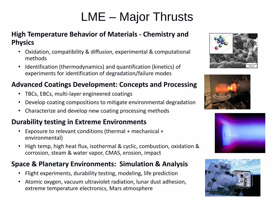
LME – Major Thrusts
High Temperature Behavior of Materials - Chemistry and Physics
• Oxidation, compatibility & diffusion, experimental & computational methods
• Identification (thermodynamics) and quantification (kinetics) of experiments for identification of degradation/failure modes
Advanced Coatings Development: Concepts and Processing• TBCs, EBCs, multi-layer engineered coatings
• Develop coating compositions to mitigate environmental degradation
• Characterize and develop new coating processing methods
Durability testing in Extreme Environments• Exposure to relevant conditions (thermal + mechanical +
environmental)
• High temp, high heat flux, isothermal & cyclic, combustion, oxidation & corrosion, steam & water vapor, CMAS, erosion, impact
Space & Planetary Environments: Simulation & Analysis• Flight experiments, durability testing, modeling, life prediction
• Atomic oxygen, vacuum ultraviolet radiation, lunar dust adhesion, extreme temperature electronics, Mars atmosphere

High Temperature Behavior of Materials
GRC identified Si(OH)4 product for reaction of SiC
with moisture – reaction is life limiting to SiC/SiC
durability in turbine engines
Experimental Thermodynamics & Kinetics Capabilities:
• Identify gaseous reaction products for unknown reactions
• Determine kinetic rate of candidate materials degradation modes
Knudsen Effusion
Mass Spectrometer
Thermo-gravimetric
Analysis (air/water/vacuum)
Computational Thermodynamics & Computational Models:
• Thermodynamics & kinetic approach• Identify degradation modes due to adverse reactions w/ adjoining
materials and environment constituents
• Code generated phase diagrams (FactSage / ThermoCalc / Dictra)
• Modeling efforts complimented with in-house experimental capabilities
• Atomistic, nanoscale, and continuum DFT materials modeling• Molecular dynamics, Metropolis/Kinetic Monte Carlo, and particle
statics/dynamics Oxygen Diffusivity in ZrO2

LME Mass Spectrometer Lab(3) unique instruments to identify gas and
vapors at high temperatures. One-of-a-kind
facility in US, only 2-3 worldwide.
• Vacuum studies based on Knudsen cell • Typical 1cm dia x 1cm high, 1 mm orifice, establish near
equilibrium, vapor effuses
• Wt loss rates relates to pressure
• Knudsen Cell Mass Spectrometers• Magnetic Sector KEMS
• Magnet sorts ions by mass-to-charge ratio
and ion intensity α vapor pressure
• High stability / resolution
• Fast Scanning Quadrupole KEMS• Electric field sorts the ions
• Thermodynamic information provided:• Heats of Vaporization & composition of vapor phases
• Activity measurements & phase diagram boundaries
• High Pressure Mass Spectrometer• Free Jet Expansion
• Allows (10-6 atm) sampling at 1 atm
• Series of differential chambers
• Eliminates cold surface condensate
• Chemical & dynamic integrity of gases
• More qualitative (approx. amts)
MagneticSector
Quadrupole

Computational Modeling
Overall Approach:
• Kinetic Monte Carlo (kMC) computer simulations of oxygen/H2O diffusion in candidate materials such as Yb2Si2O7, Y2Si2O7, and HfSiO4.
• Processes are assumed to be thermally activated.
• Consider vacancy and interstitial diffusion mechanisms.
• Migration barrier energies are computed using Density Functional Theory (DFT).
• Barrier energies are used to produce diffusivities using a kMC code developed in our laboratory.
Yb2Si2O7 Structure

• Incorporation of Si-based ceramics into turbine hot section has substantial benefits
• High temperature, low density• 1990’s: Observation that SiC undergoes rapid
recession in water vapor
• Environmental barrier coatings (EBCs) are necessary to protect the underlying ceramic
• Chemical compatibility between layers
• CTE match @ EBC/bond coat/substrate
• Thermal stability w/ limited volumetric change• Limited O2/H2O ingress & weight loss, CMAS
resistant, erosion toughness
• Total thickness of 5-10 mil (125-250 micron)
• 2000s: Development of coatings to minimize water vapor effects at 2400°F
• Current NASA goals require durable coating systems at 1482C (2700F) w/ reduced cooling
• Limited recession and good adhesion
• Traditional processing methods may not be able to meet the requirements
• Plasma Spray-Physical Vapor Deposition (PS-PVD)• Slurry casting
Advanced Coatings: Concepts
EBC
Bond Coat
SiC/SiC CMC

Environmental Barrier Coating (EBC)An external coating to protect CMC from water vapor
H2O(g) Si(OH)4(g) H2O(g) H2O(g)
SiO2 (s) + 2H2O (g) = Si(OH)4 (g)
EBCChemical
compatibility
Low stressOxidation
Resistance
Environmental durability
- H2O
- CMAS
CTE match
Phase stability
Low modulus
Sinter resistance
EBC is essential for CMC operation. Uncoated
CMC suffers rapid recession.
Oxide topcoat
Mixture interlayer
Environmental Barrier
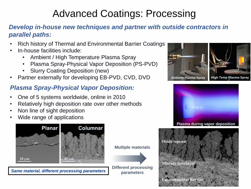
Advanced Coatings: Processing
Develop in-house new techniques and partner with outside contractors in
parallel paths:
• Rich history of Thermal and Environmental Barrier Coatings
• In-house facilities include:
• Ambient / High Temperature Plasma Spray
• Plasma Spray-Physical Vapor Deposition (PS-PVD)
• Slurry Coating Deposition (new)
• Partner externally for developing EB-PVD, CVD, DVD
Plasma Spray-Physical Vapor Deposition:
Plasma during vapor deposition
Same material, different processing parameters
• One of 5 systems worldwide, online in 2010
• Relatively high deposition rate over other methods
• Non line of sight deposition
• Wide range of applications
Ambient Plasma Spray High Temp Plasma Spray
Multiple materials
Different processing
parameters
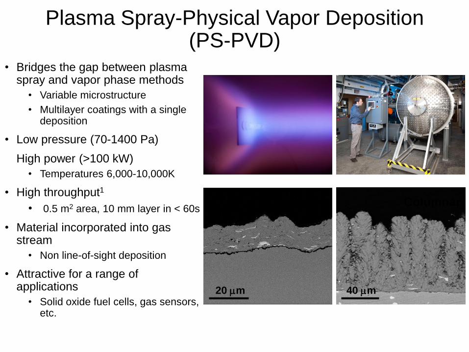
• Bridges the gap between plasma spray and vapor phase methods
• Variable microstructure
• Multilayer coatings with a single deposition
• Low pressure (70-1400 Pa)
High power (>100 kW)
• Temperatures 6,000-10,000K
• High throughput1
• 0.5 m2 area, 10 mm layer in < 60s
• Material incorporated into gas stream
• Non line-of-sight deposition
• Attractive for a range of applications
• Solid oxide fuel cells, gas sensors, etc.
20 mm
Planar
40 mm
Columnar
Plasma Spray-Physical Vapor Deposition(PS-PVD)

EBC Failure Modes10
K. N. Lee, “Environmental Barrier Coatings for CMC’s”; in Ceramic Matrix Composites, Wiley, New York (2015)
Synergies between failure modes lead to the ultimate EBC failure
CMC
SiO2
CMC
EBC
EBC
CMC
CMC
EBC
CMC
• Steam oxidation
• Recession by
water vapor
• Thermal fatigue
• Thermo-mechanical
fatigue
• Sand/Volcanic Ash Ingestion
• CMAS: Calcium-
Magnesium-Alumino-Silicate
• Erosion
• Foreign Object Damage
Bond Coat
H2O
Cycle
under
DT
H2O
Si(OH)4 (gas)
CMC
EBC
FOD
10

- Silicon oxidizes faster in H2O(g) than in air by an order of magnitude- Attributed to high solubility of H2O(g) in SiO2
- Ceramic top coat does not stop the transport of H2O(g) to Si bond coat
First Gen EBC0.9 atm pH2O + 0.1 am O2
GE Final Report – AMAIGT Program Dec. 2010
SiO2
Silicon0.9 atm pH2O + 0.1 am O2
SiliconO2 = 0.1 atm
H2O(g) Si(OH)4(g)
H2O (g)
Silicon Bond coat
Isothermal Oxidation, T = 2200oF (1204oC)
Oxidation of EBC/CMC system must be evaluated in H2O environments
Cyclic Oxidation, 2400oF, 90% H2O
Gen 2, 100h, TGO 6~7 mm
SiO2
Si
Yb2Si2O7
NASA, Unpublished data
EBC Steam Oxidation

• First integration and testing of NASA
developed CMC with the NASA
developed EBC system
• Sustained peak low cycle fatigue
(SPLCF) test with laser gradient heating
for thermomechanical validation
• Milestones have been reached for
desired temperature and loading
conditions.
Thermomechanical Testing of CMC/EBC
EBC coated CMC under stress heated by a high heat flux laser
Laser Heating
CMC with EBC
After testing
Cycle
under DT
CMC
EBCMechanical
Loading
12
13
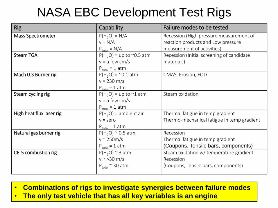
Rig Capability Failure modes to be tested
Mass Spectrometer P(H2O) = N/Av = N/APtotal = N/A
Recession (High pressure measurement of reaction products and Low pressure measurement of activities)
Steam TGA P(H2O) = up to ~0.5 atm v = a few cm/sPtotal = 1 atm
Recession (Initial screening of candidate materials)
Mach 0.3 Burner rig P(H2O) = ~0.1 atmv = 230 m/sPtotal = 1 atm
CMAS, Erosion, FOD
Steam cycling rig P(H2O) = up to ~1 atm v = a few cm/sPtotal = 1 atm
Steam oxidation
High heat flux laser rig P(H2O) = ambient air v = zero Ptotal = 1 atm
Thermal fatigue in temp gradientThermo-mechanical fatigue in temp gradient
Natural gas burner rig P(H2O) ~ 0.5 atm, v ~ 250m/sPtotal = 1 atm
RecessionThermal fatigue in temp gradient(Coupons, Tensile bars, components)
CE-5 combustion rig P(H2O) ~ 3 atmv ~ >30 m/s Ptotal ~ 30 atm
Steam oxidation w/ temperature gradientRecession(Coupons, Tensile bars, components)
NASA EBC Development Test Rigs
• Combinations of rigs to investigate synergies between failure modes
• The only test vehicle that has all key variables is an engine
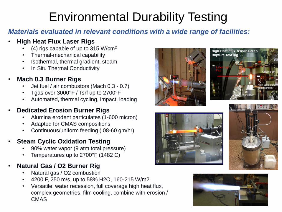
Environmental Durability TestingMaterials evaluated in relevant conditions with a wide range of facilities:
• High Heat Flux Laser Rigs• (4) rigs capable of up to 315 W/cm2
• Thermal-mechanical capability
• Isothermal, thermal gradient, steam
• In Situ Thermal Conductivity
• Mach 0.3 Burner Rigs• Jet fuel / air combustors (Mach 0.3 - 0.7)
• Tgas over 3000°F / Tsrf up to 2700°F
• Automated, thermal cycling, impact, loading
• Dedicated Erosion Burner Rigs• Alumina erodent particulates (1-600 micron)
• Adapted for CMAS compositions
• Continuous/uniform feeding (.08-60 gm/hr)
• Steam Cyclic Oxidation Testing• 90% water vapor (9 atm total pressure)
• Temperatures up to 2700°F (1482 C)
• Natural Gas / O2 Burner Rig• Natural gas / O2 combustion
• 4200 F, 250 m/s, up to 58% H2O, 160-215 W/m2
• Versatile: water recession, full coverage high heat flux,
complex geometries, film cooling, combine with erosion /
CMAS
15
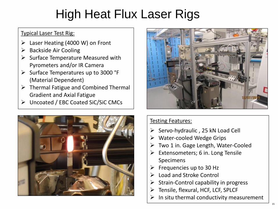
Typical Laser Test Rig:
Laser Heating (4000 W) on Front Backside Air Cooling Surface Temperature Measured with
Pyrometers and/or IR Camera Surface Temperatures up to 3000 °F
(Material Dependent) Thermal Fatigue and Combined Thermal
Gradient and Axial Fatigue Uncoated / EBC Coated SiC/SiC CMCs
(HO)
(H2O)
Testing Features:
Servo-hydraulic , 25 kN Load Cell Water-cooled Wedge Grips Two 1 in. Gage Length, Water-Cooled Extensometers; 6 in. Long Tensile
Specimens Frequencies up to 30 Hz Load and Stroke Control Strain-Control capability in progress Tensile, flexural, HCF, LCF, SPLCF In situ thermal conductivity measurement
High Heat Flux Laser Rigs

• 8 computer-controlled jet-fueled combustors in individual test cells Building 34
• Extremely efficient means of testing the durability of new jet engine materials
• Material test temperatures from 600° to 2700°F, flame temperatures to 3000ºF
• Creates the extremely hostile operating environment found in turbine engines
• Multiple or single samples tested using rotating carousels to compare materials
• Thermal cycling duplicates actual flight cycles: takeoffs, cruise, and landings
Mach 0.3 Burner Rig Facility
(1) TBC/Super-alloy, (2) Erosion,
(3) Film-cooled monolithic
ceramic, (4) Metal Turbine Blade(1)
(3)
(2)
(4)
Oxidation
Hot Corrosion
Thermal Cycle
Erosion & CMAS
Tensile
F.O.D.

Cyclic Steam Oxidation Testing
O2 H2O
QuartzWool
“Hot Cycle”
• Steam oxidation required to determine durability of EBC
• Limitation of formation and growth of SiO2 layer critical to lifetime
• Oxidation of Si-based ceramics (including Si) is an order of magnitude or more in steam
• Steam oxidation performed at NASA
• “Hot cycle” temperature 1426°C
• 0.9 atm H2O bal. O2
• 2.2 cm/sec flow rate
• 1 hour hot followed by 20 minute cool
O2 H2O
QuartzWool
“Cool Cycle”
31 Cycles at 1426°C 50 mm
• Scales formed in cyclic steam oxidation are often much thicker and more porous
• TGO scales at coating interface lead to spallation failure
18
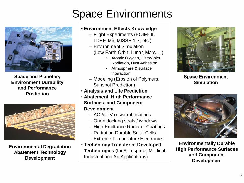
Space Environments
Space and Planetary
Environment Durability
and Performance
Prediction
Space Environment
Simulation
Environmental Degradation
Abatement Technology
Development
Environmentally Durable
High Performance Surfaces
and Component
Development
• Environment Effects Knowledge
– Flight Experiments (EOIM-III,
LDEF, Mir, MISSE 1-7, etc.)
– Environment Simulation
(Low Earth Orbit, Lunar, Mars …)• Atomic Oxygen, UltraViolet
Radiation, Dust Adhesion
• Atmosphere & surface
interaction
– Modeling (Erosion of Polymers,
Sunspot Prediction)
• Analysis and Life Prediction
• Abatement, High Performance
Surfaces, and Component
Development
– AO & UV resistant coatings
– Orion docking seals / windows
– High Emittance Radiator Coatings
– Radiation Durable Solar Cells
– Extreme Temperature Electronics
• Technology Transfer of Developed
Technologies (for Aerospace, Medical,
Industrial and Art Applications)

• Monte Carlo Analysis: 2-D Computational modeling
of atomic oxygen erosion of polymers based on
observed in-space results
• Takes into account:
• Energy dependence of reaction probability
• Angle of impact dependence on reaction
probability
• Thermalization of scattered oxygen atoms
• Partial recombination at surfaces
• Atomic oxygen scattering distribution
functions
• Modeling parameters tuned to replicate in-space
erosion
Atomic Oxygen Modeling
O2
UV Radiation
O O CO or CO2OH
LDEF Teflon FEPAO F= 7.78x10²¹ atoms/cm2

Fire damaged Atomic oxygen restoration
Atomic Oxygen Art Restoration