liquid crystal display lcd2-80 - fpssa.com.arfpssa.com.ar/sharre/17 lcd2-80 instruction manual...
TRANSCRIPT

B1P/N 53242:B1 ECN 12-0233
Document 5324210/25/2012 Rev:
Liquid Crystal DisplayLCD2-80
Instruction Manual

Fire Alarm System LimitationsWhile a fire alarm system may lower insurance rates, it is not a substitute for fire insurance!An automatic fire alarm system—typically made up of smoke detectors, heat detectors, manual pull sta-tions, audible warning devices, and a fire alarm control panel with remote notification capability—can provide early warning of a developing fire. Such a system, however, does not assure protection against property damage or loss of life resulting from a fire. The Manufacturer recommends that smoke and/or heat detectors be located throughout a protected premise following the recommendations of the current edition of the National Fire Protection Association Standard 72 (NFPA 72), manufacturer's recommenda-tions, State and local codes, and the recommendations contained in the Guides for Proper Use of System Smoke Detectors, which are made available at no charge to all installing dealers. These documents can be found at http://www.systemsensor.com/html/appli-cat.html. A study by the Federal Emergency Manage-ment Agency (an agency of the United States government) indicated that smoke detectors may not go off in as many as 35% of all fires. While fire alarm systems are designed to provide early warning against fire, they do not guarantee warning or protection against fire. A fire alarm system may not provide timely or adequate warning, or simply may not func-tion, for a variety of reasons: Smoke detectors may not sense fire where smoke cannot reach the detectors such as in chimneys, in or behind walls, on roofs, or on the other side of closed doors. Smoke detectors also may not sense a fire on another level or floor of a building. A second-floor detector, for example, may not sense a first-floor or basement fire. Particles of combustion or “smoke” from a develop-ing fire may not reach the sensing chambers of smoke detectors because:
• Barriers such as closed or partially closed doors, walls, or chimneys may inhibit particle or smoke flow.
• Smoke particles may become “cold,” stratify, and not reach the ceiling or upper walls where detec-tors are located.
• Smoke particles may be blown away from detec-tors by air outlets.
• Smoke particles may be drawn into air returns before reaching the detector.
The amount of “smoke” present may be insufficient to alarm smoke detectors. Smoke detectors are designed to alarm at various levels of smoke density. If such density levels are not created by a developing fire at the location of detectors, the detectors will not go into alarm. Smoke detectors, even when working properly, have sensing limitations. Detectors that have photoelec-tronic sensing chambers tend to detect smoldering fires better than flaming fires, which have little visible smoke. Detectors that have ionizing-type sensing chambers tend to detect fast-flaming fires better than smoldering fires. Because fires develop in different ways and are often unpredictable in their growth, nei-ther type of detector is necessarily best and a given type of detector may not provide adequate warning of a fire. Smoke detectors cannot be expected to provide ade-quate warning of fires caused by arson, children play-ing with matches (especially in bedrooms), smoking in
bed, and violent explosions (caused by escaping gas, improper storage of flammable materials, etc.). Heat detectors do not sense particles of combustion and alarm only when heat on their sensors increases at a predetermined rate or reaches a predetermined level. Rate-of-rise heat detectors may be subject to reduced sensitivity over time. For this reason, the rate-of-rise feature of each detector should be tested at least once per year by a qualified fire protection spe-cialist. Heat detectors are designed to protect prop-erty, not life. IMPORTANT! Smoke detectors must be installed in the same room as the control panel and in rooms used by the system for the connection of alarm transmission wiring, communications, signaling, and/or power. If detectors are not so located, a developing fire may damage the alarm system, crippling its ability to report a fire. Audible warning devices such as bells may not alert people if these devices are located on the other side of closed or partly open doors or are located on another floor of a building. Any warning device may fail to alert people with a disability or those who have recently consumed drugs, alcohol or medication. Please note that:
• Strobes can, under certain circumstances, cause seizures in people with conditions such as epi-lepsy.
• Studies have shown that certain people, even when they hear a fire alarm signal, do not respond or comprehend the meaning of the signal. It is the property owner's responsibility to conduct fire drills and other training exercise to make people aware of fire alarm signals and instruct them on the proper reaction to alarm signals.
• In rare instances, the sounding of a warning device can cause temporary or permanent hear-ing loss.
A fire alarm system will not operate without any elec-trical power. If AC power fails, the system will operate from standby batteries only for a specified time and only if the batteries have been properly maintained and replaced regularly. Equipment used in the system may not be techni-cally compatible with the control panel. It is essential to use only equipment listed for service with your con-trol panel. Telephone lines needed to transmit alarm signals from a premise to a central monitoring station may be out of service or temporarily disabled. For added pro-tection against telephone line failure, backup radio transmission systems are recommended. The most common cause of fire alarm malfunction is inadequate maintenance. To keep the entire fire alarm system in excellent working order, ongoing mainte-nance is required per the manufacturer's recommen-dations, and UL and NFPA standards. At a minimum, the requirements of NFPA 72 shall be followed. Envi-ronments with large amounts of dust, dirt or high air velocity require more frequent maintenance. A main-tenance agreement should be arranged through the local manufacturer's representative. Maintenance should be scheduled monthly or as required by National and/or local fire codes and should be per-formed by authorized professional fire alarm installers only. Adequate written records of all inspections should be kept.
2 LCD2-80 Instruction Manual — P/N 53242:B1 10/25/2012

Installation PrecautionsAdherence to the following will aid in problem-free installation with long-term reliability:WARNING - Several different sources of power can be connected to the fire alarm control panel. Dis-connect all sources of power before servicing. Control unit and associated equipment may be damaged by removing and/or inserting cards, modules, or intercon-necting cables while the unit is energized. Do not attempt to install, service, or operate this unit until man-uals are read and understood. CAUTION - System Re-acceptance Test after Soft-ware Changes: To ensure proper system operation, this product must be tested in accordance with NFPA 72 after any programming operation or change in site-specific software. Re-acceptance testing is required after any change, addition or deletion of system com-ponents, or after any modification, repair or adjustment to system hardware or wiring. All components, circuits, system operations, or software functions known to be affected by a change must be 100% tested. In addi-tion, to ensure that other operations are not inadver-tently affected, at least 10% of initiating devices that are not directly affected by the change, up to a maxi-mum of 50 devices, must also be tested and proper system operation verified. This system meets NFPA requirements for operation at 0-49º C/32-120º F and at a relative humidity 93% ± 2% RH (noncondensing) at 32°C ± 2°C (90°F ± 3°F). However, the useful life of the system's standby batter-ies and the electronic components may be adversely affected by extreme temperature ranges and humidity. Therefore, it is recommended that this system and its peripherals be installed in an environment with a nor-mal room temperature of 15-27º C/60-80º F. Verify that wire sizes are adequate for all initiating and indicating device loops. Most devices cannot tol-erate more than a 10% I.R. drop from the specified device voltage.
Like all solid state electronic devices, this system may operate erratically or can be damaged when sub-jected to lightning induced transients. Although no sys-tem is completely immune from lightning transients and interference, proper grounding will reduce susceptibil-ity. Overhead or outside aerial wiring is not recom-mended, due to an increased susceptibility to nearby lightning strikes. Consult with the Technical Services Department if any problems are anticipated or encoun-tered. Disconnect AC power and batteries prior to remov-ing or inserting circuit boards. Failure to do so can damage circuits. Remove all electronic assemblies prior to any drill-ing, filing, reaming, or punching of the enclosure. When possible, make all cable entries from the sides or rear. Before making modifications, verify that they will not interfere with battery, transformer, or printed circuit board location. Do not tighten screw terminals more than 9 in-lbs. Over-tightening may damage threads, resulting in reduced terminal contact pressure and difficulty with screw terminal removal. This system contains static-sensitive compo-nents. Always ground yourself with a proper wrist strap before handling any circuits so that static charges are removed from the body. Use static suppressive packaging to protect electronic assemblies removed from the unit.Follow the instructions in the installation, operating, and programming manuals. These instructions must be followed to avoid damage to the control panel and associated equipment. FACP operation and reliability depend upon proper installation.
Precau-D1-9-2005
FCC WarningWARNING: This equipment generates, uses, and can radiate radio frequency energy and if not installed and used in accordance with the instruction manual may cause interference to radio communica-tions. It has been tested and found to comply with the limits for class A computing devices pursuant to Sub-part B of Part 15 of FCC Rules, which is designed to provide reasonable protection against such interfer-ence when devices are operated in a commercial environment. Operation of this equipment in a resi-dential area is likely to cause interference, in which case the user will be required to correct the interfer-ence at his or her own expense.
Canadian RequirementsThis digital apparatus does not exceed the Class A limits for radiation noise emissions from digital appa-ratus set out in the Radio Interference Regulations of the Canadian Department of Communications. Le present appareil numerique n'emet pas de bruits radioelectriques depassant les limites applicables aux appareils numeriques de la classe A prescrites dans le Reglement sur le brouillage radioelectrique edicte par le ministere des Communications du Can-ada.
HARSH™, NIS™, and NOTI•FIRE•NET™ are all trademarks; and Acclimate® Plus, FlashScan®, NION®,NOTIFIER®, ONYX®, ONYXWorks®, UniNet®, VeriFire®, and VIEW® are all registered trademarks of HoneywellInternational Inc. Echelon® is a registered trademark and LonWorks™ is a trademark of Echelon Corporation.ARCNET® is a registered trademark of Datapoint Corporation. Microsoft® and Windows® are registeredtrademarks of the Microsoft Corporation.
©2011 by Honeywell International Inc. All rights reserved. Unauthorized use of this document is strictlyprohibited.
LCD2-80 Instruction Manual — P/N 53242:B1 10/25/2012 3

Software DownloadsIn order to supply the latest features and functionality in fire alarm and life safety technology to our customers, we make frequent upgrades to the embedded software in our products. To ensure that you are installing and programming the latest features, we strongly recommend that you download the most current version of software for each product prior to commissioning any system. Contact Technical Support with any questions about software and the appropriate version for a specific application.
Documentation FeedbackYour feedback helps us keep our documentation up-to-date and accurate. If you have any comments or suggestions about our online Help or printed manuals, you can email us.
Please include the following information:
• Product name and version number (if applicable)• Printed manual or online Help• Topic Title (for online Help)• Page number (for printed manual)• Brief description of content you think should be improved or corrected• Your suggestion for how to correct/improve documentation
Send email messages to:
Please note this email address is for documentation feedback only. If you have any technical issues, please contact Technical Services.
4 LCD2-80 Instruction Manual — P/N 53242:B1 10/25/2012
LCD2-80 Instruction Manual — P/N 53242:B1 10/25/2012 5
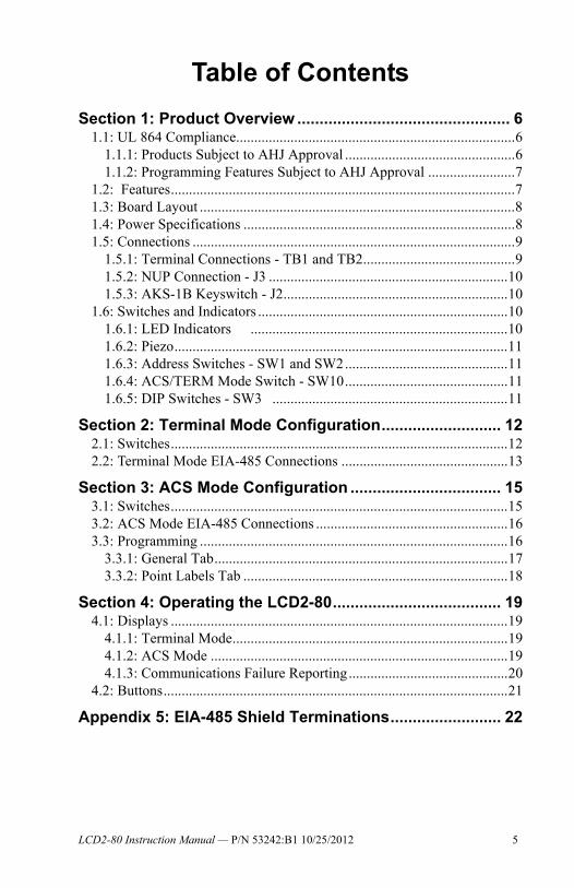
Table of Contents
Section 1: Product Overview ................................................ 61.1: UL 864 Compliance.............................................................................6
1.1.1: Products Subject to AHJ Approval ...............................................61.1.2: Programming Features Subject to AHJ Approval ........................7
1.2: Features...............................................................................................71.3: Board Layout .......................................................................................81.4: Power Specifications ...........................................................................81.5: Connections .........................................................................................9
1.5.1: Terminal Connections - TB1 and TB2..........................................91.5.2: NUP Connection - J3 ..................................................................101.5.3: AKS-1B Keyswitch - J2..............................................................10
1.6: Switches and Indicators .....................................................................101.6.1: LED Indicators .......................................................................101.6.2: Piezo............................................................................................111.6.3: Address Switches - SW1 and SW2.............................................111.6.4: ACS/TERM Mode Switch - SW10.............................................111.6.5: DIP Switches - SW3 .................................................................11
Section 2: Terminal Mode Configuration........................... 122.1: Switches.............................................................................................122.2: Terminal Mode EIA-485 Connections ..............................................13
Section 3: ACS Mode Configuration .................................. 153.1: Switches.............................................................................................153.2: ACS Mode EIA-485 Connections .....................................................163.3: Programming .....................................................................................16
3.3.1: General Tab.................................................................................173.3.2: Point Labels Tab .........................................................................18
Section 4: Operating the LCD2-80...................................... 194.1: Displays .............................................................................................19
4.1.1: Terminal Mode............................................................................194.1.2: ACS Mode ..................................................................................194.1.3: Communications Failure Reporting............................................20
4.2: Buttons...............................................................................................21
Appendix 5: EIA-485 Shield Terminations......................... 22

Section 1: Product OverviewThe LCD2-80 alphanumeric display module is an ancillary device used by Notifier fire alarm control panels including NCA-2, NFS-320, NFS2-640, and NFS2-3030. The product operates in Terminal mode, where it acts as a display interface and mimics the host control panel, or in ACS mode, where it can display custom messages.
1.1 UL 864 Compliance
1.1.1 Products Subject to AHJ Approval
This product has been certified to comply with the requirements in the Standard for Control Units and Accessories for Fire Alarm Systems, UL 864 9th Edition.
The following products have not received UL 864 9th Edition certification and may only be used in retrofit applications. Operation of the LCD2-80 with products not tested for UL864 9th Edition has not been evaluated and may not comply with NFPA 72 and/or the latest edition of UL 864. These applications will require the approval of the local Authority Having Jurisdiction (AHJ).
NOTE:The LCD2-80 should not be used as a primary display in Canada.
NOTE:The LCD2-80 should not be used as a primary display for releasing service.
• NCA • AFP-200
• NFS-640 • AFP-1010
• NFS-3030 • AM-2020
• AFP-300/400
6 LCD2-80 Instruction Manual — P/N 53242:B1 10/25/2012

Features Product Overview
1.1.2 Programming Features Subject to AHJ Approval
This product incorporates field-programmable software. The features and/or options listed below must be approved by the local AHJ.
1.2 Features• 80-character backlit LCD display.• Control switches for Acknowledge, Signal Silence, Drill System Reset,
and Step Display/Lamp Test.• ABF-1/B package with key switch option.• Local piezo sounder with alarm/trouble resound.• EIA-485 connects to control panel terminal port.
• In Terminal Mode:
• The LCD2-80 is a simplified version of the display for NCA-2, NFS-320, NFS2-640, and NFS2-3030.
• Mounts up to 6000 foot segments between units.• Up to 32 of these terminals can provide annunciation and control
from remote locations.• Device type identifiers from control panel.• Device and zone custom labels from control panel.• Device address from control panel.• EIA-485 connects to control panel terminal port.• No programming necessary — mimics the host control panel.
• In ACS Mode:• The LCD2-80 supplies a means to display a subset of the panel
message text, or to display custom messages programmed using VeriFire® Tools.
• The power-limited EIA-485 interface provided by the control panel will support the installation of devices at up to 32 addresses.
• Zone/point message display programming done in VeriFire® Tools.• European Mode display option (“Trouble” is called “Fault”).• System trouble display option.
This product incorporates field-programmable software. In order for the product to comply with the requirements in the Standard for Control Units and Accessories for Fire Alarm Systems, UL 864, certain programming features or options must be limited to specific values or not used at all as indicated below.
Program feature or option
Permitted in UL 864 (Y/N)
Possible settings
Settings permittedin UL 864
Piezo Enable/Disable
N SW3-2 ON = Piezo DisabledSW3-2 OFF =Piezo Enabled
SW3-2 OFF =Piezo Enabled
LCD2-80 Instruction Manual — P/N 53242:B1 10/25/2012 7

Product Overview Board Layout
1.3 Board Layout
1.4 Power SpecificationsCurrent Consumption @ 24 VDC
• Normal (no activity): 84 mA• Lamp Test: 105 mA• AC Fail (Piezo ON): 45 mA • AC Fail (Piezo OFF): 28 mA• Alarm (Piezo ON): 98 mA• Alarm (Piezo OFF): 85 mA
Include these currents in your power supply loading and battery calculations.
Address Switches (SW1, SW2)See Section 1.6.3 on page 11
DIP Switches (SW3) See Section 1.6.5 on page 11
AKS-1B (J2)See Section 1.5.3 on page 10
Terminal Connections (TB1, TB2)See Section 1.5.1 on page 9.
Piezo Sounder (SP1)See Section 1.6.2 on page 11
LC
D28
0wm
odes
wtc
h.w
mf
NUP Connection (J3)See Section 1.5.2 on page 10
ACS/TERM Mode Switch (SW10)See Section 1.6.4 on page 11.
Figure 1.1 LCD2-80 Board Layout
8 LCD2-80 Instruction Manual — P/N 53242:B1 10/25/2012

Connections Product Overview
1.5 Connections
1.5.1 Terminal Connections - TB1 and TB2
These connections provide 24 VDC operating power (TB1) and EIA-485 connections (TB2) to the LCD2-80.
The connections must be power-limited.
Power connections are illustrated below. Refer to “Terminal Mode EIA-485 Connections” on page 13 and “ACS Mode EIA-485 Connections” on page 16 for TB2 connection illustrations.
Power Connections (TB1)
The LCD2-80 can be powered by a +24 VDC power supply listed for fire protective signalling use that is power limited and regulated with a voltage range of +17 VDC to +28 VDC. Power can also be provided by an FACP with an integral power supply as long as the LCD2-80 is listed for use with the FACP.
The power run to the LCD2-80 must be power-limited but need not contain a Power Supervision Relay since loss of power is inherently supervised through communication loss.
-EIA-485 In-EIA-485 Out+EIA-485 In+EIA-485 Out
No connectionReference-Common Out-Common In+24 Volts Out+24 Volts InNo connection
TB1
TB2
Figure 1.2 TB1, TB2 Connections
!CAUTION:Risk of Equipment Damage!Do not power the LCD2-80 from any unfiltered power source designed for powering NAC devices. This may damage the equipment.
NOTE:If the LCD2-80 is powered from a separate supply from the control panels, the suppyling commons should be tied together and ground fault detection should be disabled in all but the primary supply.
LCD2-80 Instruction Manual — P/N 53242:B1 10/25/2012 9

Product Overview Switches and Indicators
Figure 1.3 Supplying Power to the LCD2-80
1.5.2 NUP Connection - J3
Connection for standard NUP cable for VeriFire®Tools downloads.
1.5.3 AKS-1B Keyswitch - J2
Keyswitch connector for an optional AKS-1B keyswitch. When the two pins on this interface are shorted, all five keys on the membrane panel will be ignored by the LCD2-80.
1.6 Switches and Indicators
1.6.1 LED Indicators
24 VDC (+) Common (-)
FCPS-24S6/8 TB4-9 TB4-10
NFS-320, NFS2-640 TB10 Nonresettable 24VDC+ TB10 Nonresettable 24VDC-
NFS2-3030, NCA-2 TB6+ TB6-
7654321
TB1
From Main Power Supply
(-) Common
(+) 24 VDC Power
(+) (-) To next LCD2-80 LCD2-80
LED Color Function
Alarm Red Indicates an Alarm condition on the FACP. This LED will remain lit until all alarm conditions have been cleared.
Supervisory Yellow Indicates a Supervisory condition on the FACP. This LED will remain lit until all supervisory conditions have been cleared.
System Trouble
Yellow Indicates a Trouble condition on the FACP. This LED will remain lit until all trouble conditions have been cleared.
Point Disable Yellow Indicates that a point on the FACP has been disabled. This LED will remain lit until the point has been re-enabled.
Signal Silence
Yellow Indicates that any or all silenceable outputs have been silenced. This LED will be lit until the outputs have resounded or a reset is performed on the FACP.
Other Yellow Indicates that an Other or Security event has occurred on the FACP. This LED will remain lit until all other and security events have been cleared.
Table 1.1 LED Functions
NOTE: The LEDs operate in Terminal mode only when used with the NFS-320, NFS2-640, and NFS2-3030/NCA-2. They do not activate for off-normal events from legacy panels in Terminal mode.
NOTE:The second and eighth LEDs are reserved for Future Use.
10 LCD2-80 Instruction Manual — P/N 53242:B1 10/25/2012
Switches and Indicators Product Overview
1.6.2 Piezo
The LCD2-80 sounder will be activated when any new alarm or trouble is received from the panel. It is silenced by the ACKNOWLEDGE switch.
1.6.3 Address Switches - SW1 and SW2
In ACS mode, these rotary switches must be set to the address of the LCD2-80 on the EIA-485 line. Set the TENS rotary switch (SW1) to the number in the tens position of the LCD2-80’s address. Set the ONES rotary switch (SW2) to the ones position.
1.6.4 ACS/TERM Mode Switch - SW10
Set to A (ACS mode) or T (Terminal mode).
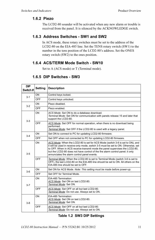
1.6.5 DIP Switches - SW3
DIP Switch #
Setting Description
3-1ON Control keys locked.
OFF Control keys unlocked.
3-2ON Piezo disabled.
OFF Piezo enabled.
3-3
ON ACS Mode: Set ON to do a database download.Terminal Mode: Set ON for communication with panels release 15 and later that support the LCD2-80.
OFF ACS Mode: Set OFF for normal operation, when there is no download being performed.Terminal Mode: Set OFF if the LCD2-80 is used with a legacy panel.
3-4ON Set ON to connect to PC for updating LCD2-80 firmware.
OFF Set OFF when not connected to PC for updating LCD2-80 firmware.
3-5
ON ACS Mode: When the LCD2-80 is set for ACS Mode (switch 3-6 is set to ON), and it will be used in receive-only mode, switch 3-5 must be set to ON. Otherwise, set to OFF. When in ACS receive-transmit mode the panel supervises the LCD2-80, but the LCD2-80 does not have control of the fire alarm control panel; it only annunciates fire alarm control panel events.
OFF Terminal Mode: When the LCD2-80 is set to Terminal Mode (switch 3-6 is set to OFF), the last LCD2-80 on the EIA-485 line should be set to ON. All others on the EIA-485 line should be set to OFF.
3-6ON Set ON for ACS Mode. Note: This setting must be made before power-up.
OFF Set OFF for Terminal Mode.
3-7
ON EIA-485 Termination:ACS Mode: Set ON on last LCD2-80.Terminal Mode: Set ON.
OFF ACS Mode: Set OFF on all but last LCD2-80.Terminal Mode: Do not use. Always set to ON.
3-8
ON EIA-485 Termination:ACS Mode: Set ON on last LCD2-80.Terminal Mode: Set ON.
OFF ACS Mode: Set OFF on all but last LCD2-80.Terminal Mode: Do not use. Always set to ON.
Table 1.2 SW3 DIP Settings
LCD2-80 Instruction Manual — P/N 53242:B1 10/25/2012 11

Section 2: Terminal Mode ConfigurationWhen the LCD2-80 is set for Terminal Mode it operates like a CRT terminal without full keyboard capability, but with the advantages of 24 VDC power, wall mount, and multiple terminal location with Acknowledge, Signal Silence, Drill and Reset.
Notes:
• EIA-485 circuits have a maximum of 6000 feet between units.• Up to 32 LCD2-80s may be used on the EIA-485 circuit (consult control
panel’s battery calculations). • Between each LCD2-80 are four wires: A twisted-shielded pair for data
communications and an open pair for 24 VDC power. The return circuit only requires two wires for data communication.
• The EIA-485 interface used in Terminal Mode should not be confused with an EIA-485 circuit used in ACS Mode (annunciator interface).
• The EIA-485 terminal interface does not support the use of RPT-485 repeaters.
2.1 SwitchesDIP switches at SW3 must be set for terminal mode, and SW10 (ACS/TERM Mode switch) must be set to TERM.
Setting the DIP switches:
Refer to “DIP Switches - SW3” on page 11 for a full explanation of all the switch settings. For switches 3-1, 3-2, and 3-4, set as necessary according to the explanations. For 3-3, 3-5, 3-6, 3-7 and 3-8, set as follows for Terminal Mode:
3-3 - Set ON if this LCD2-80 is being used with an ONYX panel. Set OFF if it will be used with a legacy panel.3-5 - Set ON on last LCD2-80 on the EIA-485. Otherwise, set OFF.
NOTE:When LCD2-80s are used on the same EIA-485 circuit asLCD-80s, the LCD2-80s must be at the furthest end of the circuit from the panel.
Terminal Mode
EIA-485
Terminal Mode EIA-485 Return
(Maximum 6000 feet from last LCD2-80 to FACP)
24 VDC
Fire Alarm Control Panel
LC
D28
0-tm
sys2
a.w
mf-
tmsy
s2.w
mf
Figure 2.1 Block Diagram of LCD2-80s in Terminal Mode
12 LCD2-80 Instruction Manual — P/N 53242:B1 10/25/2012
Terminal Mode EIA-485 Connections Terminal Mode Configuration
3-6 - Set OFF.3-7 and 3-8 - Set ON.
Setting the ACS/TERM Mode switch:
Set this switch (SW10) to T (TERM).
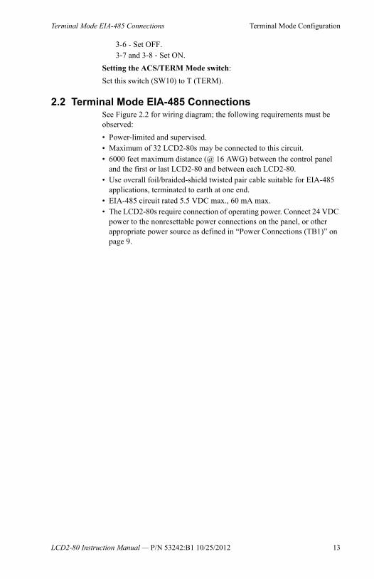
2.2 Terminal Mode EIA-485 ConnectionsSee Figure 2.2 for wiring diagram; the following requirements must be observed:
• Power-limited and supervised.• Maximum of 32 LCD2-80s may be connected to this circuit.• 6000 feet maximum distance (@ 16 AWG) between the control panel
and the first or last LCD2-80 and between each LCD2-80.• Use overall foil/braided-shield twisted pair cable suitable for EIA-485
applications, terminated to earth at one end.• EIA-485 circuit rated 5.5 VDC max., 60 mA max.• The LCD2-80s require connection of operating power. Connect 24 VDC
power to the nonresettable power connections on the panel, or other appropriate power source as defined in “Power Connections (TB1)” on page 9.
LCD2-80 Instruction Manual — P/N 53242:B1 10/25/2012 13
Terminal Mode Configuration Terminal Mode EIA-485 Connections
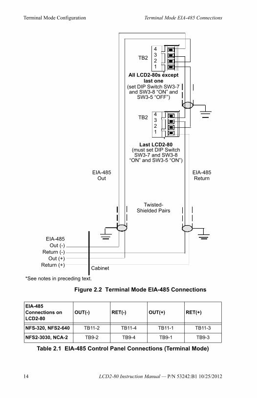
Figure 2.2 Terminal Mode EIA-485 Connections
Last LCD2-80 (must set DIP Switch SW3-7 and SW3-8
“ON” and SW3-5 “ON”)
All LCD2-80s except last one
(set DIP Switch SW3-7 and SW3-8 “ON” and
SW3-5 “OFF”)
TB2
TB2
Twisted-Shielded Pairs
EIA-485 Return
EIA-485Out (-)
Return (-)Out (+)
Return (+)
EIA-485 Out
Cabinet
*See notes in preceding text.
4321
4321
EIA-485 Connections on LCD2-80
OUT(-) RET(-) OUT(+) RET(+)
NFS-320, NFS2-640 TB11-2 TB11-4 TB11-1 TB11-3
NFS2-3030, NCA-2 TB9-2 TB9-4 TB9-1 TB9-3
Table 2.1 EIA-485 Control Panel Connections (Terminal Mode)
14 LCD2-80 Instruction Manual — P/N 53242:B1 10/25/2012

Section 3: ACS Mode ConfigurationThe primary application for the LCD2-80 in ACS Mode is to display messages with text that is a subset of the panel message text, or custom messages programmed using VeriFire® Tools.
The power-limited EIA-485 interface provided by the control panels will support the installation of devices at up to 32 addresses. Devices other than the LCD2-80 that can be installed at one of the 32 addresses include the ACS, LDM, and SCS modules.
The LCD2-80 can be mounted in ABF-1B, ABS-1TB, or ABS-1B backbox (not the ABS-1) or can mount on one slot of the CHS-4 chassis. The ABF-1B may include an AKS-1B keyswitch and APJ-1B phone jack.
3.1 SwitchesDIP switches at SW3 must be set for ACS mode, and SW10 (ACS/TERM Mode switch) must be set to ACS.
Setting the DIP switches:
Refer to “DIP Switches - SW3” on page 11 for a full explanation of all the switch settings. For switches 3-1, 3-2, and 3-4, set as necessary according to the explanations. DIP Switches 3-3, 3-5, 3-6, 3-7 and 3-8, are unique to ACS Mode configuration:
3-3 - Set ON to do a database download. Set OFF when download is complete.3-5 - Set ON if this LCD2-80 will be used in receive-only mode. Otherwise, set OFF. Note: Maximum receive-only mode shadow addresses for the LCD2-80 in ACS mode is 4 (four).3-6 - Set ON.3-7 and 3-8 - Set ON on last LCD2-80.
Setting the ACS/TERM Mode switch:
Set this switch (SW10) to A (ACS).
Setting the Address Switches:
Set the address rotary switches to the desired address. See “Address Switches - SW1 and SW2” on page 11.
EIA-485: Maximum of 6,000 feet total wire length
LC
D2
80
-AC
Sm
od
e.w
mf
FACP
Figure 3.1 Block Diagram of LCD2-80s in ACS Mode
LCD2-80 Instruction Manual — P/N 53242:B1 10/25/2012 15
ACS Mode Configuration ACS Mode EIA-485 Connections
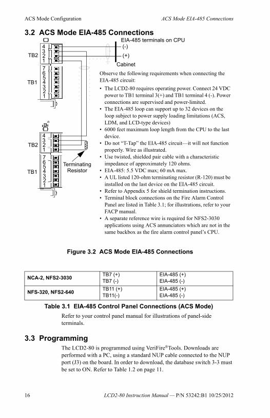
3.2 ACS Mode EIA-485 Connections
Refer to your control panel manual for illustrations of panel-side terminals.
3.3 ProgrammingThe LCD2-80 is programmed using VeriFire®Tools. Downloads are performed with a PC, using a standard NUP cable connected to the NUP port (J3) on the board. In order to download, the database switch 3-3 must be set to ON. Refer to Table 1.2 on page 11.
Figure 3.2 ACS Mode EIA-485 Connections
TB2
TB1
TB2
TB1
4321
4321
765
4321
4321
765 Terminating
Resistor
Observe the following requirements when connecting the EIA-485 circuit:
• The LCD2-80 requires operating power. Connect 24 VDC power to TB1 terminal 3(+) and TB1 terminal 4 (-). Power connections are supervised and power-limited.
• The EIA-485 loop can support up to 32 devices on the loop subject to power supply loading limitations (ACS, LDM, and LCD-type devices)
• 6000 feet maximum loop length from the CPU to the last device.
• Do not “T-Tap” the EIA-485 circuit—it will not function properly. Wire as illustrated.
• Use twisted, shielded pair cable with a characteristic impedance of approximately 120 ohms.
• EIA-485: 5.5 VDC max; 60 mA max.• A UL listed 120-ohm terminating resistor (R-120) must be
installed on the last device on the EIA-485 circuit.• Refer to Appendix 5 for shield termination instructions.• Terminal block connections on the Fire Alarm Control
Panel are listed in Table 3.1; for illustrations, refer to your FACP manual.
• A separate reference wire is required for NFS2-3030 applications using ACS annunciators which are not in the same backbox as the fire alarm control panel’s CPU.
(-)EIA-485 terminals on CPU
(+)
Cabinet
NCA-2, NFS2-3030TB7 (+)TB7 (-)
EIA-485 (+)EIA-485 (-)
NFS-320, NFS2-640TB11 (+)TB11(-)
EIA-485 (+)EIA-485 (-)
Table 3.1 EIA-485 Control Panel Connections (ACS Mode)
16 LCD2-80 Instruction Manual — P/N 53242:B1 10/25/2012
Programming ACS Mode Configuration
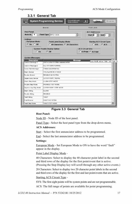
3.3.1 General Tab
Host Panel:
Node ID - Node ID of the host panel.
Panel Type - Select the host panel type from the drop-down menu.
ACS Addresses:
Start - Select the first annunciator address to be programmed.
End - Select the last annunciator address to be programmed.
Settings:
European Mode - Set European Mode to ON to have the word “fault” appear in the display.
Point Label Display Mode -
40 Characters: Select to display the 40 character point label in the second and third rows of the display for the first point/event that is active. (Pressing the Step Display key will scroll through any other active events.)
20 Characters: Select to display two 20 character point labels in the second and third rows of the display for the first and last point/events that are active.
Starting ACS Circuit Type -
SYS: The first eight points will be system points and are not programmable.
ACS: The full range of points are available for point programming.
Figure 3.3 General Tab
LCD2-80 Instruction Manual — P/N 53242:B1 10/25/2012 17
ACS Mode Configuration Programming
System Trouble/Display Option - Set ON to have a general alarm or trouble message display in the system if there is no annunciator point mapped to the device.
ACS Circuit Size - 64 or 96 points.
System Messages -
Description: Fixed message titles. The message associated with the description will display on the LCD2-80 when called for by a panel command.
Message: These fields are populated with default messages that may be changed by the programmer.
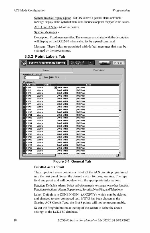
3.3.2 Point Labels Tab
Installed ACS Circuit
The drop-down menu contains a list of all the ACS circuits programmed into the host panel. Select the desired circuit for programming. The type field and point grid will populate with the appropriate information.
Function: Default is Alarm. Select pull-down menu to change to another function. Function selections: Alarm, Supervisory, Security, Non-Fire, and Telephone.
Label: Default is to ZONE NNNN (AXXPYY), which may be deleted and changed to user-composed text. If SYS has been chosen as the Starting ACS Circuit Type, the first 8 points will not be programmable.
Select the Program button at the top of the screen to write the above settings to the LCD2-80 database.
Figure 3.4 General Tab
18 LCD2-80 Instruction Manual — P/N 53242:B1 10/25/2012

Section 4: Operating the LCD2-80
4.1 DisplaysThe display consists of four 20-space rows, 80 characters total. Following are formats for different message types.
4.1.1 Terminal Mode
In terminal mode, the LCD2-80 directly displays event information from the FACP terminal interface, without alteration.
4.1.2 ACS Mode
In ACS Mode, the LCD2-80 will display custom message labels from its database.
Normal Message
Displays when the system has no off-normal events.
*Note: The LEDs operate in Terminal mode only when used with the NFS-320, NFS2-640, and NFS2-3030/NCA-2. They do not activate for off-normal events from legacy panels in Terminal mode.*Note: If Acknowledge, Silence, and Reset switches are enabled for system control, access security must be provided by mounting the LCD2-80 in a locked fire alarm cabinet, or annunciator backbox model ABF-1B or ABS-1TB with AKS-1B key switch option.
Display Step/LampTest
Drill
*Acknowledge*Signal Silence*Reset
AlarmFuture Use
SupervisorySystem Trouble
Point DisableSignal Silence
OtherFuture Use
Figure 4.1 LED and Button Designations
LED Locations(See “LED Indicators” on page 10 for functions).
Buttons:See “Buttons” on page 21 below for
functions.
ROSEWOOD HOSPITALNORTH HALL FLOOR 3
ALL SYSTEM NORMAL
20 characters across
4 rows40 character custom message 1
system normal banner custom message 2blank
LCD2-80 Instruction Manual — P/N 53242:B1 10/25/2012 19

Operating the LCD2-80 Displays
40 Character Event Messages
Displays when one or more events are active in the system. Rows two and three display the custom label for the first active point.
If there is more than one event, press the Display Step/Lamp Test key to step through a display of the custom point labels of subsequent events.
20-Character Event Messages
Displays when one or more events are active in the system. The second row displays the first event point; the third row displays the last event point. There is no step function for this display. Only the highest priority event type will display at one time.
Event priorities, in order of highest to lowest, are as follows: alarm, super-visory, security, non-fire with piezo, non-fire without piezo, trouble. A higher priority event that becomes active while a lower priority event is already active will cause the 20-character event message to change from displaying the lower-priority event to displaying the higher-priority event.
Display Illumination
If “SYS” is selected in programming as the Starting ACS Circuit Type:
When AC power is applied, the display backlight will turn on. When the panel sends an AC FAIL message, the backlight will turn on as follows:• Alarm events - the backlight will turn on and stay on.• Pressing “Step Display” will turn on the backlight for 60 seconds.Note that an AC Fail message is sent from the panel only when a “Starting ACS Circuit Type” of “SYS” is entered in initial programming.
If “ACS” is selected in programming as the Starting ACS Circuit Type:
When AC power is applied, the display backlight will turn on. Trouble events from the panel will turn off the backlight. Other events will turn on the backlight, and it will stay on until the events are cleared. Pressing “Step/Display” will turn on the backlight for 60 seconds.
4.1.3 Communications Failure Reporting
If the LCD2-80 fails to receive communications from the panel for a period of over one minute, it will activate its local sounder and display the following message: COMMUNICATIONS FAIL
FIRE ALARMNORTH HALL FLOOR 3NURSE STATION001ALARM 000TROUBLE
event banner (alarm, trouble, etc.)
40 character custom point labelalarm/trouble count string. Alarm count includes all events except troubles.
ALARM BANNERNORTH HALL FLOOR 3NORTH HALL FLOOR 2002ALARM 000TROUBLE
event banner (alarm, trouble, etc.)20 character point label for first event point
alarm/trouble count string. Alarm count includes all events except troubles.
20 character point label for last event point.
20 LCD2-80 Instruction Manual — P/N 53242:B1 10/25/2012

Buttons Operating the LCD2-80
4.2 ButtonsThe LCD2-80 emulates from one to 32 annunciators.
Acknowledge
When the Acknowledge button is pressed on the front panel, the LCD2-80 sends an acknowledge command to the control panel, and silences the local sounder. In Terminal Mode, additional key punches will step through what the host panel shows for next events.
Silence
When the Silence button is pressed on the front panel, the LCD2-80 sends a signal silence command to the control panel.
System ResetWhen the System Reset button is pressed on the front panel, the LCD2-80 sends a reset command to the control panel.
DrillWhen the Drill button on the front panel is pressed and held for 2 seconds, the LCD2-80 sends a drill command to the control panel.
Display Step/Lamp Test If the LCD display backlight has been turned off due to a trouble condition in the system, momentarily pressing this switch will illuminate the display for 60 seconds. If this switch is pressed and held in excess of 3 seconds, the LCD2-80 will go into Lamp Test mode. During Lamp Test, all LEDs will light, all segments of the display will turn on and the piezo will sound for the duration the switch is pressed. Upon release of the switch, the LCD2-80 software version number will briefly be displayed and then the LCD2-80 will return to normal operation.
When the LCD2-80 is set for ACS mode, this button may be used to step the display through multiple events. Events types are displayed in the following order; alarms, supervisories, security alarms, non-fire events, troubles, and outputs. This is a local function and does not send an acknowledge command to the control panel. If a trouble condition has turned off the backlighting, it also causes the backlit display to illuminate for about one minute, and while held, turns on all LCD segments (lamp test).
NOTE:The Acknowledge, Silence and Reset and Drill buttons will serve no function if the LCD2-80 has been set for Receive-Only operation (DIP switch SW1-1 has been set ON)
LCD2-80 Instruction Manual — P/N 53242:B1 10/25/2012 21

22 LCD2-80 Instruction Manual — P/N 53242:B1 10/25/2012
Appendix 5: EIA-485 Shield Terminations
The EIA-485 circuit must be wired using a twisted-shielded pair cable having a Characteristic Impedance of 120 ohms, +/- 20%. Do not run cable adjacent to, or in the same conduit as, 120-volt AC service, noisy electrical circuits that are powering mechanical bells or horns, audio circuits above 25 Vrms, motor control circuits, or SCR power circuits. All enclosures, including the FACP backbox, must be connected to earth ground! Never use the shield for grounding purposes.
Note on remote power supplies:
When the LCD2-80 is powered from a separate power supply, use a separate conductor to connect the main power supply common terminal to the remote power supply common terminal. Disable earth fault detection on the remote power supply.
When employing the LCD2-80 in Terminal Mode:
Terminate the EIA-485 shields at either the cabinet (when not in conduit) or at system common (when in conduit) as outlined below.
When the EIA-485 shield is not in conduit: At each respective LCD2-80 enclosure (except the first on the loop), terminate the shield coming in from the previous LCD2-80 at the outside of the cabinet backbox (earth ground). Let the outgoing (to next LCD2-80) shield float (no connection). Shield termination between LCD2-80s can only occur at the receiving end - the end connected to P1 Terminals 2 and 4.
When the EIA-485 shield is in conduit: At each respective LCD2-80 enclosure (except the first on the loop), terminate the shield coming in from the previous LCD2-80 at system common. Let the shield going out to next LCD2-80 shield float (no connection). Shield termination between LCD2-80s can only occur at the receiving end—the end connected to LCD2-80 P1 Terminals 2 and 4.

Manufacturer Warranties and Limitation of LiabilityManufacturer Warranties. Subject to the limitations set forthherein, Manufacturer warrants that the Products manufactured byit in its Northford, Connecticut facility and sold by it to itsauthorized Distributors shall be free, under normal use andservice, from defects in material and workmanship for a period ofthirty six months (36) months from the date of manufacture(effective Jan. 1, 2009). The Products manufactured and sold byManufacturer are date stamped at the time of production.Manufacturer does not warrant Products that are notmanufactured by it in its Northford, Connecticut facility but assignsto its Distributor, to the extent possible, any warranty offered by themanufacturer of such product. This warranty shall be void if aProduct is altered, serviced or repaired by anyone other thanManufacturer or its authorized Distributors. This warranty shallalso be void if there is a failure to maintain the Products and thesystems in which they operate in proper working conditions.
MANUFACTURER MAKES NO FURTHER WARRANTIES, ANDDISCLAIMS ANY AND ALL OTHER WARRANTIES, EITHEREXPRESSED OR IMPLIED, WITH RESPECT TO THEPRODUCTS, TRADEMARKS, PROGRAMS AND SERVICESRENDERED BY MANUFACTURER INCLUDING WITHOUTLIMITATION, INFRINGEMENT, TITLE, MERCHANTABILITY, ORFITNESS FOR ANY PARTICULAR PURPOSE.MANUFACTURER SHALL NOT BE LIABLE FOR ANYPERSONAL INJURY OR DEATH WHICH MAY ARISE IN THECOURSE OF, OR AS A RESULT OF, PERSONAL, COMMERCIALOR INDUSTRIAL USES OF ITS PRODUCTS.
This document constitutes the only warranty made byManufacturer with respect to its products and replaces all previouswarranties and is the only warranty made by Manufacturer. Noincrease or alteration, written or verbal, of the obligation of thiswarranty is authorized. Manufacturer does not represent that itsproducts will prevent any loss by fire or otherwise.
Warranty Claims. Manufacturer shall replace or repair, atManufacturer's discretion, each part returned by its authorizedDistributor and acknowledged by Manufacturer to be defective,provided that such part shall have been returned to Manufacturerwith all charges prepaid and the authorized Distributor hascompleted Manufacturer's Return Material Authorization form.The replacement part shall come from Manufacturer's stock andmay be new or refurbished. THE FOREGOING ISDISTRIBUTOR'S SOLE AND EXCLUSIVE REMEDY IN THEEVENT OF A WARRANTY CLAIM.
Warn-HL-08-2009.fm
LCD2-80 Instruction Manual — P/N 53242:B1 10/25/2012 23

World Headquarters12 Clintonville Road
Northford, CT 06472-1610 USA203-484-7161
fax 203-484-7118
www.notifier.com