liquefied gas z400c pump installation - corken.com · 3 3 1 5 6 10d d 2 4 no! don't use...
TRANSCRIPT
Z400CLIQUEFIED GASPUMP INSTALLATIONENGINEERING DATA ANDDESIGN HANDBOOK
2
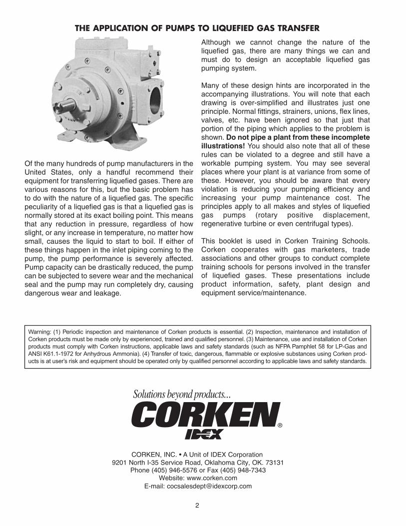
Of the many hundreds of pump manufacturers in theUnited States, only a handful recommend theirequipment for transferring liquefied gases. There arevarious reasons for this, but the basic problem hasto do with the nature of a liquefied gas. The specificpeculiarity of a liquefied gas is that a liquefied gas isnormally stored at its exact boiling point. This meansthat any reduction in pressure, regardless of howslight, or any increase in temperature, no matter howsmall, causes the liquid to start to boil. If either ofthese things happen in the inlet piping coming to thepump, the pump performance is severely affected.Pump capacity can be drastically reduced, the pumpcan be subjected to severe wear and the mechanicalseal and the pump may run completely dry, causingdangerous wear and leakage.
Although we cannot change the nature of theliquefied gas, there are many things we can andmust do to design an acceptable liquefied gaspumping system.
Many of these design hints are incorporated in theaccompanying illustrations. You will note that eachdrawing is over-simplified and illustrates just oneprinciple. Normal fittings, strainers, unions, flex lines,valves, etc. have been ignored so that just thatportion of the piping which applies to the problem isshown. Do not pipe a plant from these incompleteillustrations! You should also note that all of theserules can be violated to a degree and still have aworkable pumping system. You may see severalplaces where your plant is at variance from some ofthese. However, you should be aware that everyviolation is reducing your pumping efficiency andincreasing your pump maintenance cost. Theprinciples apply to all makes and styles of liquefiedgas pumps (rotary positive displacement,regenerative turbine or even centrifugal types).
This booklet is used in Corken Training Schools.Corken cooperates with gas marketers, tradeassociations and other groups to conduct completetraining schools for persons involved in the transferof liquefied gases. These presentations includeproduct information, safety, plant design andequipment service/maintenance.
Warning: (1) Periodic inspection and maintenance of Corken products is essential. (2) Inspection, maintenance and installation ofCorken products must be made only by experienced, trained and qualified personnel. (3) Maintenance, use and installation of Corkenproducts must comply with Corken instructions, applicable laws and safety standards (such as NFPA Pamphlet 58 for LP-Gas andANSI K61.1-1972 for Anhydrous Ammonia). (4) Transfer of toxic, dangerous, flammable or explosive substances using Corken prod-ucts is at user’s risk and equipment should be operated only by qualified personnel according to applicable laws and safety standards.
CORKEN, INC. • A Unit of IDEX Corporation9201 North I-35 Service Road, Oklahoma City, OK. 73131
Phone (405) 946-5576 or Fax (405) 948-7343Website: www.corken.com
E-mail: [email protected]
THE APPLICATION OF PUMPS TO LIQUEFIED GAS TRANSFER
3
3
1
5 6
10D
D
2
4
No!
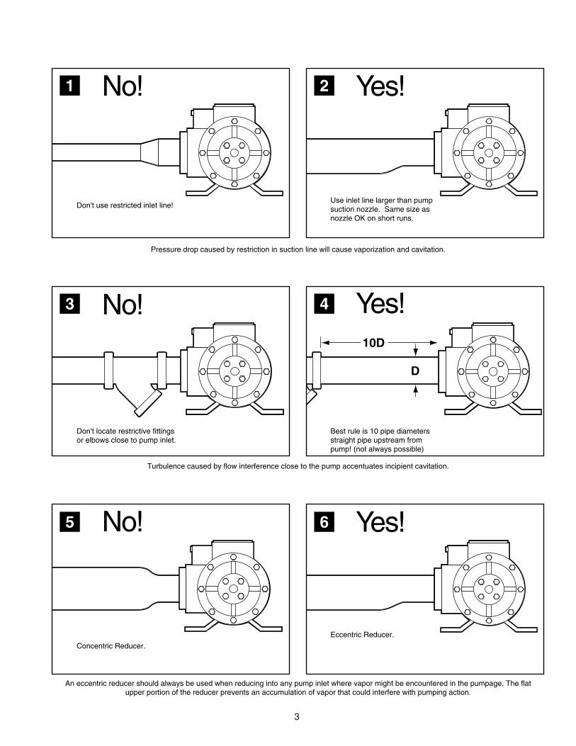
Don't use restricted inlet line!
Yes!
Use inlet line larger than pumpsuction nozzle. Same size asnozzle OK on short runs.
No!
An eccentric reducer should always be used when reducing into any pump inlet where vapor might be encountered in the pumpage. The flatupper portion of the reducer prevents an accumulation of vapor that could interfere with pumping action.
Pressure drop caused by restriction in suction line will cause vaporization and cavitation.
Turbulence caused by flow interference close to the pump accentuates incipient cavitation.
Yes!
No!
Concentric Reducer.
Don't locate restrictive fittingsor elbows close to pump inlet.
Yes!
Eccentric Reducer.
Best rule is 10 pipe diametersstraight pipe upstream frompump! (not always possible)
4
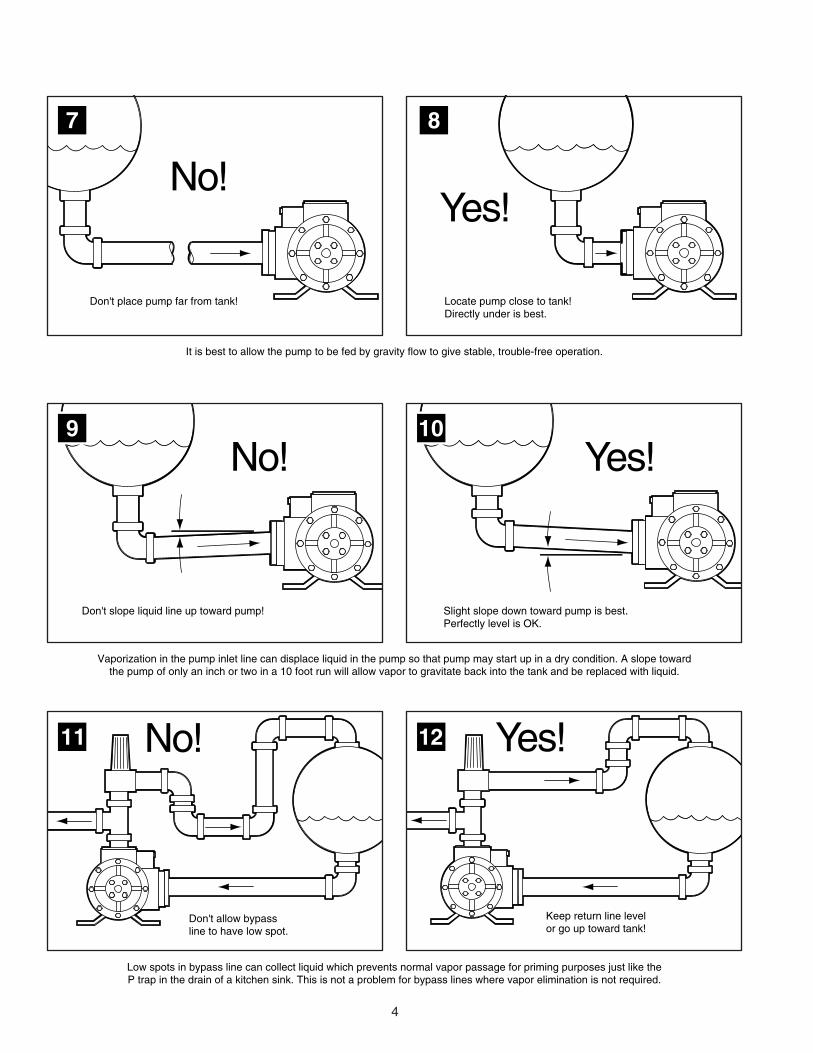
Locate pump close to tank!Directly under is best.
Don't place pump far from tank!
Vaporization in the pump inlet line can displace liquid in the pump so that pump may start up in a dry condition. A slope towardthe pump of only an inch or two in a 10 foot run will allow vapor to gravitate back into the tank and be replaced with liquid.
Low spots in bypass line can collect liquid which prevents normal vapor passage for priming purposes just like theP trap in the drain of a kitchen sink. This is not a problem for bypass lines where vapor elimination is not required.
It is best to allow the pump to be fed by gravity flow to give stable, trouble-free operation.
8
11 12No! Yes!
Yes!
Keep return line level or go up toward tank!
No!
No!
Don't slope liquid line up toward pump!
10
Yes!
Slight slope down toward pump is best.Perfectly level is OK.
Don't allow bypassline to have low spot.
9
7

5
Low capacity flow through large lines often does not sweep out vapor. Flow occurs like liquid in a flume. Drawings 15 and 16 would allow vapor slugsto be drawn into the small pump causing erratic performance. Drawing 17 shows the best chance for stable feed into a small pump from a large line.
Since liquefied gases boil when drawn into a pump by its own suction, the pump must be fed by gravity flow to give stable, trouble-free operation.
16
17 18
No!
No!
When feeding small pump from tee off oflarge supply line, come out the bottom of pipe line, not top or side!
When feeding small pump from large main line, don't tee off the side, tee out the bottom.
Yes!
When feeding smallpump from large mainline, don't tee off the side,tee out the bottom!
Main Line
15
Vapor Liquid
Some tanks have vapor connections in the bottom, these have stand pipes inside. A bottom vapor connection can be used instead of a top opening with any of the drawings in this booklet.
Locate pump below tank level... the lower the better!
7 Yes!14Don't locatepump abovelevel of liquidfeeding pump.Product mustbe able to flowby gravity intopump.
13 No!
Main Line
Main Line

6
No! Yes!
19 20
23
No!Long Discharge Line Back Check Valve
Large quantity of liquid in long lines allows continuing vaporizationover long periods of time during which the pump will be full ofvapor and will run dry during start-up attempts.
Use soft-seat back check valve near pump in long discharge linesto prevent vaporization from coming back through pump when pumpis not in operation. Long lines would be considered anything longer than 50'.
24
Yes!
Positive closure of back check valve preventsproper vapor return for pump priming.
Back Check ValveExcess Flow Check Valve
Necessary for proper vapor elimination when using priming type bypass valves.
Where pumping from underground storage must be done, consult instruction book IF103.
This is not a problem where vapor elimination is not required.
By-Pass Line By-Pass Line
Better...
22
Where tank must be buried,use one size smaller dip tube pipe, shallowtank, keep suction line short and use onlyCorken B166 bypass valve. Plan on higher pump maintenance and repair costs on all underground pumping systems.
Bad...21
No underground liquefied gas pumpingsystem is good. In this case, the tank is too deep, the line is too long, and the suction pipe is too large.

7
Inquire about Corken's duplex-series pump set.
29 30No!Don't pipe bypass line back into suction piping! Heat buildup in recirculated products causes flashing of liquid to vapor with immediate cavitation and ultimate dry-running. This is why the bypass relief valves which are built into many positive displacement pumps should not be used for normal bypass action when handling liquefied gases. The internal valve should be considered to be a back-up safety relief in addition to a back-to-tank bypass valve and should be set to relieve at a pressure 10 to 20 psi higher than the working bypass. Some built-in bypass valves have the capability of being piped back-to-tank so check with the pump manufacturer.
Yes!Always pipe bypass back to tank! Make sure bypass line is large enough to handle full pump flow without excessive pressure build-up. Note that bypass line must be capable of bypassing full pump capacity without excessive pressure build-up. High pressure rise can cause bypass valve to chatter and vibrate.
Multiple pumps fedfrom same main line.
27
Good...
Parallel piping ofliquefied gas pumps.
28
Best...
Pumps operatingin parallel.
26
OK...25
Bad...
Pump No. 1 is starved because of venturi action at tee. This would be acceptable for installations where both pumps would never operate at the same time.
8
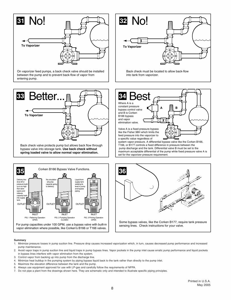
Back check must be located to allow back-flowinto tank from vaporizer.
On vaporizer feed pumps, a back check valve should be installed between the pump and to prevent back-flow of vapor from entering pump.
32
35
No!
Better... Best
No!
34
For pump capacities under 100 GPM, use a bypass valve with built-invapor elimination where possible, like Corken's B166 or T166 valves.
Corken B166 Bypass Valve Functions.
33
31
To Vaporizer To Vaporizer
To Vaporizer
A B
Delivery line shut-off or pressure build up is so high that valve opens and relieves capacity back into supply tank.
Liquid from supply tank seeking its level in pump and bypass piping.
No circulation - all pump capacity going to delivery.
INLET INLET INLET
OUTLETOUTLETOUTLET
FIG. 1 Relieving OperationOPEN
FIG. 2 Pumping OperationCLOSED
FIG. 3 Priming OperationOPEN
36
Some bypass valves, like the Corken B177, require tank pressuresensing lines. Check instructions for your valve.
Back check valve protects pump but allows back flow through bypass valve into storage tank. Use back check without spring loaded valve to allow normal vapor elimination.
Where A is a constant pressure bypass control valve and B is Corken B166 bypassand vapor elimination valve.
Valve A is a fixed pressure bypass like the Fisher 98H which limits the feed pressure into the vaporizer to a specific value regardless of system vapor pressure. A differential bypass valve like the Corken B166, T166, or B177 controls a fixed difference in pressure between the pump discharge and the tank. Differential valve B must be set to the maximum acceptable differential of the pump while fixed pressure valve A is set for the vaporizer pressure requirement.
Summary1. Minimize pressure losses in pump suction line. Pressure drop causes increased vaporization which, in turn, causes decreased pump performance and increased
pump maintenance.2. Avoid vapor traps in pump suction line and liquid traps in pump bypass lines. Vapor pockets in the pump inlet cause erratic pump performance and liquid pockets
in bypass lines interfere with vapor elimination from the system.3. Control vapor from backing up into pump from the discharge line.4. Minimize heat buildup in the pumping system by piping bypass liquid back to the tank rather than directly to the pump inlet.5. Maximize the elevation difference between the tank and the pump.6. Always use equipment approved for use with LP-gas and carefully follow the requirements of NFPA.7. Do not pipe a plant from the drawings shown here. They are schematic only and intended to illustrate specific piping principles.
Printed in U.S.A.May 2005