national aeronautics and space … of nozzle or inlet, ft equivalent diameter - diameter of a single...
TRANSCRIPT
* c
r,’
NASA RESEARCH ON THE AERODYNAMICS OF
JET VTOL ENGINE INSTALLATIONS
By Richard E. Kuhn and Marion 0. McKinney, Jr.
NASA Langley Research Center Langley Station, Hampton, Va.
Presented at the AGARD Specialist Meeting on Aerodynamics of Power Plant Installation
N 65- 3 4 9 9 8 GPO PRICE $
e?/ / CFSTI PRICE(S) $
I-
L1
m (ACCESSION NUMBER1 ITHRUI
I, :- a
t: (PAGES)
Hard copy (HC) A
4
CATEGORY)
Microfiche (M F) *su ff 653 July65
Tullahoma, Tennessee October 25 - 27, 1965
NATIONAL AERONAUTICS AND SPACE ADMINISTRATION
WASHINGTON
https://ntrs.nasa.gov/search.jsp?R=19650025397 2018-05-26T14:35:17+00:00Z

ABSTRACT 97953
T h i s paper summarizes some of t he more per t inent r e s u l t s of NASA
invest igat ions re la ted t o the aerodynamics of j e t VTOL engine i n s t a l l a -
t i ons . It shows t h a t there i s a base loss i n hovering due t o suction
forces creased on the underside of the fuselage by the entrainment of
ambient a i r i n the sl ipstream, and t h a t the magnitude of t h i s e f f ec t i s
re la ted t o the turbulence i n the j e t stream and i t s consequent r a t e of
mixing with ambient a i r . It a l so shows that there a r e large l i f t l o s ses
and p i tch ing moments due t o jet-free-stream in te r fe rence and that these
cha rac t e r i s t i c s can be s igni f icant ly a l te red by proximity t o the ground.
And, f i n a l l y , it shows t h a t simple bellmouth i n l e t s give good pressure
recovery and low d i s to r t ion f o r ve r t i ca l ly mounted l i f t engines i f the
i n l e t l i p radius i s su f f i c i en t ly large, but t h a t such i n l e t s a r e not
su i tab le f o r windmill s t a r t i n g of the engines.
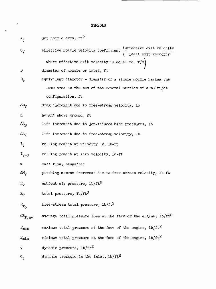
SYMBOLS
Aj
cV
D
De
h
aLs
lV
ZV=O
m
PO
PT
P TO
DT, av
Pmax
Pmin
Q
q i
jet nozzle area, f t 2
Effect ive e x i t ve loc i ty Idea l e x i t ve loc i ty
e f f ec t ive nozzle veloci ty coefficient
where e f f ec t ive e x i t veloci ty i s equal t o T/m 1 diameter of nozzle o r i n l e t , f t
equivalent diameter - diameter of a s ingle nozzle having the
same area as the sum of the several nozzles of a mul t i j e t
configuration, f t
drag increment due t o free-stream veloci ty , l b
height above ground, f t
l i f t increment due t o jet-induced base pressures, i b
l i f t increment due t o free-stream veloci ty , l b
r o l l i n g moment a t ve loc i ty V, l b - f t
r o l l i n g moment a t zero veloci ty , lb - f t
mass flow, slugs/sec
pitching-moment increment due t o free-stream veloci ty , l b - f t
ambient a i r pressure, l b / f t 2
t o t a l pressure, l b / f t 2
free-stream t o t a l pressure, l b / f t2
average t o t a l pressure loss a t the face of the engine, i b / f t 2
maximum t o t a l pressure a t the face of the engine, l b / f t 2
minimum t o t a l pressure a t the face of the engine, l b / f t 2
dynamic pressure, l b / f t 2
dynamic pressure i n the i n l e t , l b / f t 2

S
T
vi
w i X
U
P
'a
P O
dynamic pressure a t j e t nozzle, l b / f t 2
dynamic pressure a t s t a t ion x-distance downstream of nozzle,
l b / f t 2
wing o r base p l a t e area, f t 2
thrust, l b , o r temperature, O F
temperature a t the nozzle, OF
free-stream veloci ty , f t / s e c
veloci ty i n i n l e t , f t / s e c
veloci ty i n j e t , f t / s e c
i n l e t airflow, lb/sec
distance downstream of nozzle, f t
angle of a t tack , deg
angle of s ides l ip , deg
a i le ron def lect ion, downward def lec t ion i s pos i t ive , deg
a i r density i n f r e e stream, s lugs / f t3
a i r densi ty i n j e t , s lugs / f t3
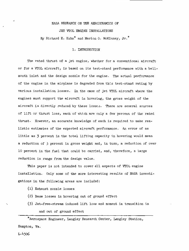
NASA RESEARCH ON THE AERODYNAMICS OF
JET VTOL ENGINE INSTALLATIONS
x By Richard E. Kuhn" and Marion 0. McKinney, Jr.
1. INTRODUCTION
The ra ted t h r u s t of a j e t engine, whether f o r a conventional a i r c r a f t
o r f o r a VTOL a i r c r a f t , i s based on i t s tes t -s tand performance with a b e l l -
mouth i n l e t and the design nozzle f o r t h e engine.
of t he engine i n the airplane i s degraded from t h i s tes t -s tand r a t ing by
various i n s t a l l a t i o n losses . I n the case of je t VTOL a i r c r a f t where the
engines must support t he a i r c r a f t i n hovering, t h e gross weight of the
a i r c r a f t i s d i r e c t l y reduced by these losses. There a re several sources
of l i f t or thrust l o s s , each of which a r e only a few percent of the rated
t h r u s t . However, an accurate knowledge of each i s required t o make rea-
l i s t i c estimates of t he expected a i r c r a f t performance.
l i t t l e as 3 percent i n the t o t a l l i f t i n g capacity i n hovering would mean
a reduction of 3 percent i n gross weight and, i n tu rn , a reduction of over
10 percent i n the f u e l t h a t could be carried, and, therefore , a la rge
reduction i n range from the design value.
The ac tua l performance
An e r r o r of as
This paper i s not intended t o cover all aspects of VTOL engine
i n s t a l l a t i o n .
ga t ions i n the following areas are included:
Only some of the more in te res t ing r e s u l t s of NASA inves t i -
(1) Exhaust nozzle losses
(2) Base lo s ses i n hovering out of ground e f f e c t
( 3 ) Jet-free-stream induced lift l o s s and moment i n t r ans i t i on i n
and out of ground e f f e c t
* Aerospace Engineer, Langley Research Center, Langley Stat ion,
Hampton, Va.
L-4506
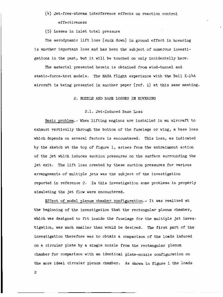
(4) Jet-free-stream interference e f f e c t s on react ion control
effect iveness
( 5 ) Losses i n i n l e t t o t a l pressure
The aerodynamic l i f t l o s s (suck down) i n ground e f f e c t i n hovering
i s another important loss and has been the subject of numerous inves t i -
gations i n the past , but it w i l l be touched on only inc identa l ly here.
The mater ia l presented herein i s obtained from wind-tunnel and
s ta t ic - force- tes t models.
a i r c r a f t i s being presented i n another paper ( r e f . 1) a t t h i s same meeting.
The NASA f l i g h t experience with the Be l l X-14A
2. NOZZLE AND BASE LOSSES I N HOVERING
2.1. Jet-Induced Base Loss
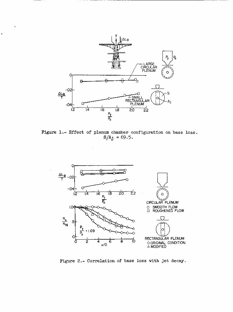
Basic problem.- When l i f t i n g engines a re in s t a l l ed i n an a i r c r a f t t o
exhaust v e r t i c a l l y through the bottom of the fuselage o r wing, a base loss
which depends on several f ac to r s i s encountered. This loss , a s indicated
by the sketch a t the top of f igure 1, arises from t h e entrainment act ion
of the j e t which induces suction pressures on the surface surrounding the
j e t ex i t . The l i f t l o s s created by these suction pressures f o r various
arrangements of multiple je ts was the subject of the inves t iga t ion
reported i n reference 2. I n this inves t iga t ion some problems i n properly
simulating the je t flow were encountered.
Effect of model plenum chamber configuration.- It w a s rea l ized a t
t h e beginning of the invest igat ion t h a t t he rectangular plenum chamber,
which was designed t o f i t ins ide the fuselage f o r t he mult iple j e t inves-
t iga t ion , was much smaller than would be desired. The first pa r t of t h e
invest igat ion therefore was t o obtain a comparison of t h e loads induced
on a circular p l a t e by a s ingle nozzle from the rectangular plenum
chamber f o r comparison with an i d e n t i c a l plate-nozzle configuration on
t h e more idea l c i r cu la r plenum chamber.
2
As show i n f igure 1 t h e loads

induced on the c i r cu la r p l a t e mounted on the o r ig ina l rectangular plenum
were four t o f i v e times as large as those induced on t h e same s i ze p l a t e
on the c i r cu la r plenum chamber with a clean nozzle. Surveys of t he e x i t
flow from the rectangular plenum indicated a d i s to r t ed ve loc i ty d i s t r i -
bution with a loss a t t he center, whereas the flow from the c i r cu la r
plenum chamber had a f l a t d is t r ibu t ion . Also it w a s obvious that the
flow from the rectangular plenum chamber was extremely rough and it w a s
suspected that this extreme turbulence of the flow was causing the higher
induced loads. Two steps were taken i n a n attempt t o check t h i s hypothesis.
The rectangular plenum chamber was modified by i n s t a l l a t i o n of some f a i r i n g s
and a red is t r ibu t ion of the o r i f i c e s feeding the a i r i n to the chamber t o
improve t h e qua l i t y of t he flow. Secondly, a strut was i n s t a l l e d about
1 diameter upstream of the nozzle on the c i rcu lar plenum chamber t o pro-
duce a roughened flow.
ve loc i ty d i s t r ibu t ion than was present on the o r ig ina l rectangular plenum
chamber.
changes increased t h e l i f t l o s s f o r the cyl indrical plenum chamber and
g rea t ly reduced the losses f o r t he rectangular plenum chamber.
changes i n the l i f t losses did not correlate with the e x i t ve loc i ty
d i s t r ibu t ion .
This a l so produced a much grea te r d i s to r t ion of t he
A s shown by t h e l i f t - l o s s curves a t the top of f igure 2, these
These
The l i f t l o s ses w e r e found t o correlate with the rate of decay of
t h e j e t with dis tance downstream from the e x i t as shown by the curves a t
t h e bottom of f igu re 2.
t h e dynamic pressure d i s t r ibu t ion a t a distance x downstream of the
nozzle divided by the dynamic pressure at t h e nozzle as a function of
dis tance from the nozzle i n nozzle diameters.
o r i g i n a l rectangular plenum chamber exhibited t h e most rapid decay of
dynamic pressure and produced the highest l i f t losses .
c i r c u l a r plenum chamber with smooth flow had the lowest decay rate and
These curves present t h e r a t i o of t he peak of
A s w i l l be noted, t h e
The o r ig ina l
3

t h e l o w e s t l i f t losses . The modified rectangular plenum chamber and the
c i rcu lar chamber with the roughened flow had similar lift losses and
similar decay curves.
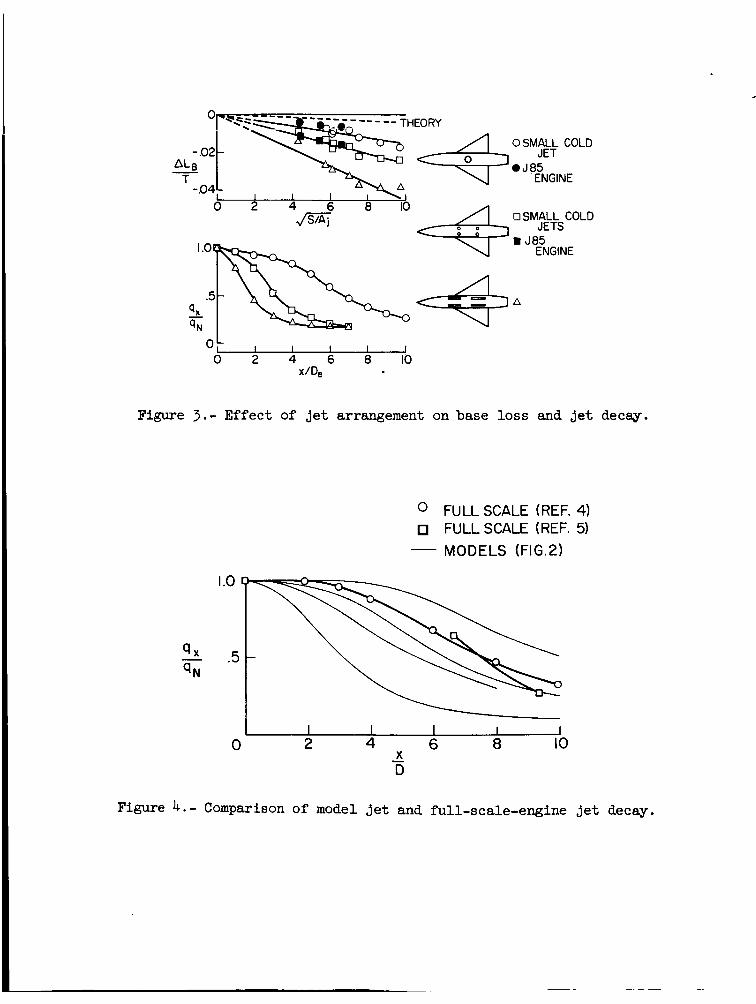
The correlat ion between the r a t e of decay of the j e t and the base
losses induced by the j e t i s t o be expected; both the base loss and the
j e t decay are caused by the act ion of the j e t i n entraining a i r and both
should be proportional t o t h e r a t e of entrainment. This cor re la t ion has
a l s o been found t o hold f o r the mult iple- je t configurations as shown i n
f igure 3 .
chamber.
i n terms of equivalent j e t diameters where
of a single j e t which would contain a l l of the area of the multiple je ts .
An empirical correlat ion of the base l o s s with the r a t e of decay of t he
j e t was developed i n reference 2 which produced the following expression:
These data were obtained w i t h t he modified rectangular plenum
Here the decay curves a re presented as a function of dis tance
represents t he diameter De
i s the maximum r a t e of decay of the dynamic pressure i n
\" t) max
the j e t and I
decay ra te occurs,
Additional data on
i s the dis tance downstream a t which t h i s maxi.mum
t h a t is , t h e in f l ec t ion point of the decay curve.
t h e e f f e c t of wing height on nozzle project ion below
t h e fuselage a re given i n reference 2.
Small-scale-large-scale comparison. - The preceding base-loss data
were obtained using small cold j e t s with an equivalent diameter of
2.25 inches. I n view of the importance of t h e qua l i t y of t h e flow i n the
4

j e t es tabl ished i n t h i s study a second invest igat ion ( r e f . 4) was under-
taken using a fu l l - sca l e 585 engine.
a l t e rna te t a i l pipes; one f o r a s ingle- je t invest igat ion and one w i t h
spec ia l exhaust ducting t o produce a four- je t configuration. The inves t i -
gat ions were run with three d i f fe ren t s izes of rectangular p l a t e s t o pro-
duce three d i f f e ren t r a t i o s of p l a t e area t o j e t area. The comparison of
these real engine data, shown by the darkened symbols i n f igure 3 , with
t h e model r e s u l t s ind ica tes good agreement.
The engine was equipped with two
The cor re la t ion between the base loss and the r a t e of decay of the
j e t as presented above ind ica tes a need for information on the decay r a t e
f o r ac tua l j e t engines. Decay curves f o r only two fu l l - sca l e j e t engines
could be found (refs. 4 and 5 ) and these are compared with the decay
curves f o r the model j e t s used i n the previous invest igat ion as shown i n
f igu re 4. These l imited fu l l - sca l e data indicate t h a t these engines a t
l e a s t are only s l i g h t l y b e t t e r than the modified plenum chamber config-
ura t ion of t he small-scale invest igat ion and not as good as t h e c i r cu la r
plenum chamber where special a t t en t ion was directed toward achieving a
good qua l i ty j e t . It i s doubtful, however, that a l l je t engines w i l l
have decay curves similar t o the two shown here. This i s pa r t i cu la r ly
true of l i f t engines which may use annular nozzles t o decrease t h e i r
length o r other spec ia l nozzles t o promote a rapid decay o r t o f a c i l i -
t a t e vector ing of the flow.
t h e decay curves f o r the various engines and nozzles t h a t may be used i n
a je t 71ToL a i r c r a f t .
It appears highly desirable t o determine
The importance of t he j e t decay rate on other interference problems
such as t h e suck down within ground ef fec t i n hovering and t h e je t - f ree-
stream interference e f f ec t s induced i n t r ans i t i on f l i g h t have not been
determined. It appears log ica l , however, t h a t there should be some
5

e f f e c t s and it would appear desirable i n the fu ture t o determine the
decay r a t e of the j e t s used i n any model invest igat ions.
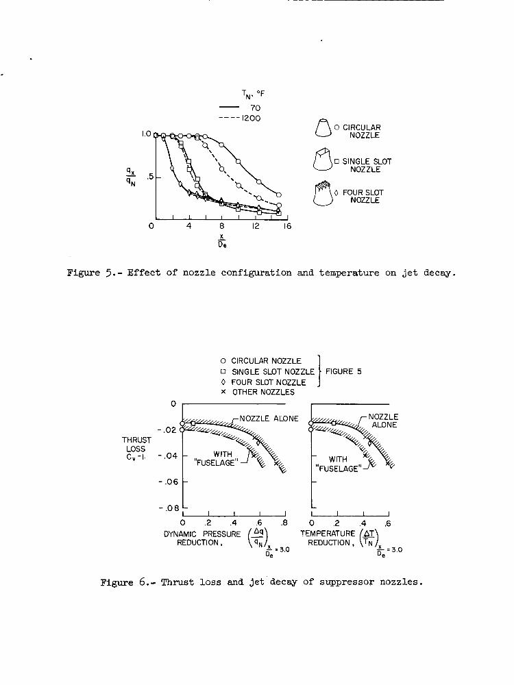
2.2. Exhaust Velocity Suppression
One of t he problems t h a t may face je t VTOL a i r c r a f t i s t h a t of the
poten t ia l erosion of the ground by t h e j e t b l a s t .
po ten t ia l of various nozzle configurations f o r re l ieving t h i s problem by
promoting rapid decay of j e t ve loc i ty with dis tance downstream of the
nozzle i s reported i n references 6 and 7.
nozzles investigated a re shown i n f igu re 5 . All th ree of t he nozzles
a re convergent but the s l o t nozzles have one important fea ture which does
not show c l ea r ly i n the i l l u s t r a t i o n .
between the small s ides a t the end of each s l o t . Decay curves were meas-
ured for a l l of the nozzles a t two j e t temperatures - TO0 F and 1200° F.
A s can be seen i n f igure 5 , a rapid decay can be obtained by using a
multiple element nozzle arrangement and the temperature of t h e je t a i r
does not have an appreciable e f f e c t on t h e decay r a t e except fo r t he
c i rcu lar nozzle.
An invest igat ion of t he
Decay curves f o r th ree of t he
They have a 5' divergent angle
2.3. Nozzle Losses
Nozzle th rus t l o s ses and temperature decay r a t e s as well a s dynamic
pressure decay r a t e s were measured f o r a c i r cu la r nozzle, a 12-segment
nozzle, a s ingle-s lot nozzle, and nine mult iple-s lot nozzle configurations
w i t h var ia t ions in s l o t aspect r a t i o , s l o t spacing, and divergence angles
of t h e small walls of each s l o t .
i dea l th rus t and measured t h r u s t ) on these nozzles i s p lo t ted i n f igure 6
as a function of the dynamic pressure reduction 4 and the j e t tempera-
ture reduction A!T a t a dis tance of 3 diameters from the nozzle. The
th rue t loss presented i s the difference between the idea l t h r u s t and the
measured th rus t and includes both i n t e r n a l and ex terna l losses . The
6
The t h r u s t l o s s (difference between
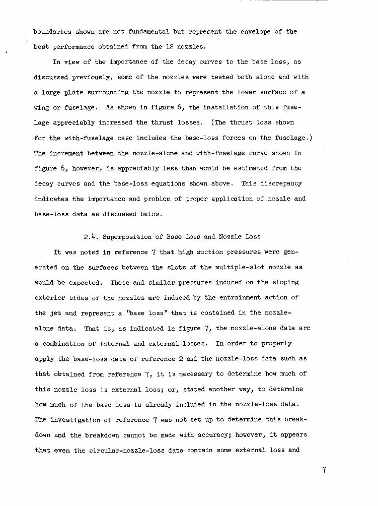
boundaries shown
bes t performance
a re not fundamental but represent the envelope of t he
obtained from the 12 nozzles.
I n view of the importance of the decay curves t o the base loss , as
discussed previously, some of the nozzles were tes ted both alone and with
a la rge p l a t e surrounding the nozzle t o represent t he lower surface of a
wing o r fuselage.
l age appreciably increased the t h r u s t losses.
f o r the with-fuselage case includes the base-loss forces on the fuselage.)
The increment between the nozzle-alone and with-fuselage curve shown i n
f igure 6, however, i s appreciably less than would be estimated from the
decay curves and the base-loss equations shown above. This discrepancy
indica tes t h e importance and problem of proper appl icat ion of nozzle and
base-loss data as discussed below.
A s shown i n f igu re 6, the i n s t a l l a t i o n of t h i s fuse-
(The th rus t l o s s shown
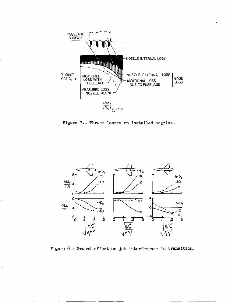
2.4. Superposition of Base Loss and Nozzle Loss
It was noted i n reference 7 t h a t high suction pressures were gen-
e ra ted on the surfaces between the s l o t s of t h e mult iple-s lot nozzle as
would be expected. These and similar pressures induced on the sloping
ex te r io r s ides of the nozzles a r e induced by the entrainment act ion of
t he j e t and represent a "base loss" t h a t is contained i n the nozzle-
alone da ta . That is , a s indicated i n figure 7, the nozzle-alone data a re
a combination of i n t e rna l and ex terna l losses. I n order t o properly
apply t h e base-loss data of reference 2 and t h e nozzle-loss data such as
t h a t obtained from reference 7, it i s necessary t o determine how much of
t h i s nczzle loss i s external loss ; or, s ta ted another way, t o determine
how much of the base l o s s i s already included i n the nozzle-loss data.
The inves t iga t ion of reference 7 was not s e t up t o determine t h i s break-
down and t h e breakdown cannot be made with accuracy; however, it appears
that even t h e circular-nozzle-loss data contain some externa l loss and
7

that anywhere from 1/3 t o 1/2 of the nozzle losses could be ex terna l
1.osses.
If the s l o t s a re far enough apar t (as with a s ingle s l o t per engine
on a multiengine configuration) ground proximity can give favorable pres-
sures between the s l o t s a s indicated below. The spacing of multiple
s l o t s on a s ingle engine nozzle, as investigated i n reference 7, i s too
close t o experience t h i s favorable e f f e c t , however.
3. INTERFERXNCE EFFECTS I N TWSITION
The l o s s i n l i f t and the nose-up pi tching moment created by suction
pressures induced beside and behind the j e t s by interference w i t h t he
free-stream flow i n t r ans i t i on f l i g h t have been the subject of numerous
invest igat ions by NASA and many other organizations (see r e f s . 9 and 10,
f o r instance) . Most of these invest igat ions have been made out of ground
e f f e c t and w i t h only the e x i t flow simulated.
been made t o inves t iga te the e f f ec t s of ground proximity and t o inves t i -
gate the poss ib i l i t y of mutual interference e f f e c t s between the i n l e t and
e x i t flows.
Two recent s tud ies have
3.1. Ground Effec ts on J e t Interference
The e f f e c t s of ground proximity on the l o s s i n l i f t and nose-up
pitching moment induced on a wing-body combination f o r s i x d i f f e ren t
arrangements of v e r t i c a l j e t s were invest igated i n reference 10.
three of these configurations a re presented i n f igure 8 t o show the com-
parison of the induced e f f e c t s out of ground e f f e c t with those obtained
a t a height of 1 ef fec t ive diameter. The da ta shown here represent
only the jet-induced forces due t o free-stream ve loc i ty and due t o ground
proximity. The d i r e c t t h r u s t of t he j e t , t h e base loss, and the aero-
dynamic forces corresponding t o the power-off condition have been
8
Data f o r

subtracted from the data t o leave only the interference l i f t s and moments
due t o ve loc i ty and ground.
e f f ec t ive ve loc i ty r a t i o , as suggested i n reference 11, which i s t h e
The data a re presented as a function of t he
square root of the r a t i o of f r e e stream t o j e t momentum per u n i t area,
and which takes in to account the difference i n densi ty r e su l t i ng from
differences i n j e t temperature.
The da ta of f igure 8 indicate some s ignif icant e f f e c t s of t h e ground
on the interference e f f ec t s . For the s ingle- je t case a very la rge suck
down w a s experienced i n hovering (e f fec t ive ve loc i ty r a t i o of 0) i n
ground e f f ec t , but t he addi t ional l i f t l o s s due t o ve loc i ty was only
s l i g h t l y affected by the ground. The induced pitching moment due t o
veloci ty , however, was g rea t ly reduced indicat ing t h a t t he suction pres-
sures behind the j e t were probably reduced by ground e f f e c t and those
beside the j e t were increased. The four- je t case, a s would be expected,
shows considerably l e s s suck down due t o ground e f f e c t a t zero e f f ec t ive
ve loc i ty r a t i o and shows a marked reduction i n both the l i f t and pi tching
moment induced by forward veloci ty thus indicating a general reduction i n
the induced suction pressures. The two-slot configurations which had a
favorable ground e f f e c t a t zero speed experienced a s l i g h t increase i n
in te r fe rence e f f ec t s due t o forward velocity. I n general , the data of
reference 10 and f igu re 8 indica te t h a t the e f f e c t s of ground proximity
on the jet-free-stream e f fec t s are highly configuration dependent and
t h a t no general conclusions can be drawn a t t h i s t i m e .
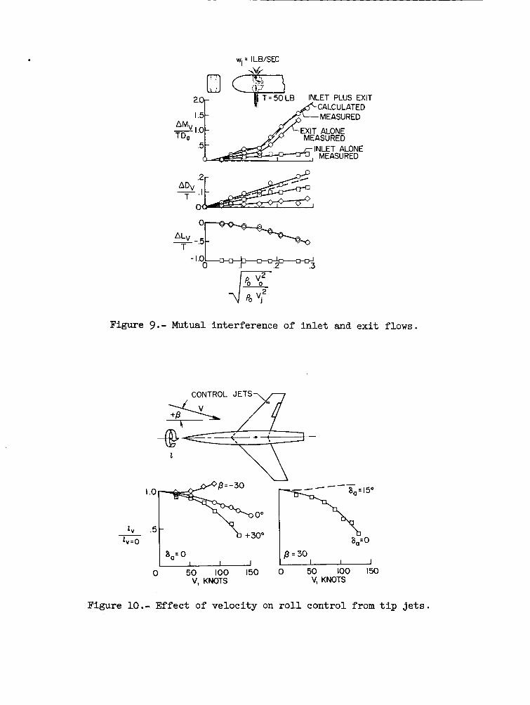
3.2. Mutual Inlet-Exi t Interference Ef fec t s
The question of t h e app l i cab i l i t y of the pr inc ip le of superposit ion
t o the problems of e x i t in te r fe rence e f f ec t s and i n l e t interference
e f f e c t s i n combination has frequently been raised; t h a t is, can the e x i t
e f f e c t s be measured on one r i g and the i n l e t e f f e c t s on another and the
9
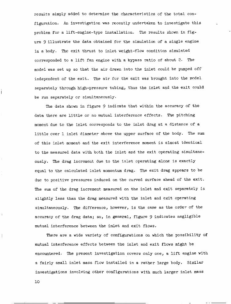
r e su l t s simply added t o determine the cha rac t e r i s t i c s of the t o t a l con-
f igurat ion.
problem f o r a l if t-engine-type i n s t a l l a t i o n .
u re 9 i l l u s t r a t e the data obtained f o r the simulation of a s ingle engine
i n a body.
corresponded t o a l i f t fan engine with a bypass r a t i o of about 2.
model was set up so t h a t the a i r drawn in to the i n l e t could be pumped off
independent of t he e x i t . The a i r f o r t he e x i t was brought i n t o the model
separately through high-pressure tubing, thus the i n l e t and the e x i t could
be run separately o r simultaneously.
An invest igat ion was recent ly undertaken t o invest igate t h i s
The r e s u l t s shown i n f i g -
The e x i t t h rus t t o i n l e t weight-flow condition simulated
The
The data shown i n f igure 9 indicate t h a t within the accuracy of t he
da ta there a r e l i t t l e o r no mutual in te r fe rence e f f ec t s .
moment due t o the i n l e t corresponds t o the i n l e t drag a t a dis tance of a
l i t t l e over 1 i n l e t diameter above the upper surface of the body.
of t h i s i n l e t moment and the e x i t interference moment i s almost i den t i ca l
t o the measured data with both the i n l e t and t h e e x i t operating simultane-
ously.
equal t o the calculated i n l e t momentum drag.
due t o pos i t ive pressures induced on the curved surface ahead of t he e x i t .
The sum of the drag increment measured on the i n l e t and e x i t separately i s
s l igh t ly l e s s than the drag measured with t h e i n l e t and e x i t operating
simultaneously.
accuracy of t h e drag data; so, i n general , f igure 9 indica tes negl igible
mutual interference between t h e i n l e t and e x i t flows.
The pi tching
The sum
The drag increment due t o the i n l e t operating alone i s exact ly
The e x i t drag appears t o be
The difference, however, i s the same as the order of the
There a r e a wide va r i e ty of configurations on which the p o s s i b i l i t y of
mutual interference e f f e c t s between t h e i n l e t and e x i t flows might be
encountered.
a f a i r l y small i n l e t mass flow i n s t a l l e d i n a r a t h e r la rge body. Similar
invest igat ions involving other configurations with much l a r g e r i n l e t mass
10
The present invest igat ion covers only one, a lift engine with
flow and with the i n l e t and e x i t i n much closer proximity than w a s pos-
s i b l e i n t h e present simple model w i l l be required before it can be s ta ted
conclusively t h a t there are no in l e t - ex i t mutual interference e f f e c t s t o
be concerned with.,
3.3 Interference Effec ts on Reaction Controls i n Transi t ion
The losses i n l i f t induced by t h e jet-free-stream interference e f f e c t s
discussed i n the previous section have been found t o be a function of the
r a t i o of the model planform area t o j e t area. This f a c t has suggested
t h a t t he effect iveness of reaction-control j e t s such as the ro l l -cont ro l
j e t s near the wing t i p may suffer s ign i f icant losses i n effect iveness i n
t r a n s i t i o n i n view of the very high ratios of wing area t o j e t area
involved i n such in s t a l l a t ions . A wind-tunnel invest igat ion of t h i s
problem was undertaken i n which the rol l -control j e t s were operated a t a
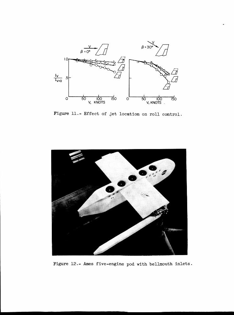
pressure r a t i o of 6. Results a r e shown i n f igures 10 and 11 i n terms of
t h e r a t i o of r o l l control a t a given ve loc i ty t o the r o l l control pro-
duced by t h e react ion j e t i n hovering as a f'unction of fu l l - sca le a i r -
c r a f t ve loc i ty . The data are shown f o r the case where two j e t s i n tandem
were used t o provide the necessary reaction control moment. The expected
reduction i n control effect iveness with forward speed w a s found f o r the
case of 0' s ides l ip angle.
a t a pos i t ive s ides l ip def lect ion and grea t ly reduced, and i n f a c t con-
ver ted t o a s l i gh t increase i n effectiveness, a t a negative s ides l ip angle.
These e f f e c t s of s i d e s l i p angle are much la rger than ant ic ipated and a re
not present ly understood. The favorable e f f e c t s of t he negative s ides l ip
case give hope t h a t when the reasons f o r these la rger e f f e c t s a r e under-
stood configurations may be designed which w i l l minimize o r eliminate the
loss i n effectiveness. The significance of the lo s s i n effect iveness f o r
t h e worst encountered s i d e s l i p angle of 30°, i s shown i n the p lo t a t the
The lo s s i n effect iveness was g rea t ly increased
11

r igh t of f igure 10 which shows t h a t 13' deflect ion of each a i le ron i s
required t o compensate f o r t h i s l o s s i n effect iveness . Thus, a la rge
pa r t of the normal a i le ron controls i s used fo r t h i s purpose and the
t o t a l r o l l control f o r a typ ica l a i rp lane i n t r ans i t i on from hovering t o
normal f l i g h t may not be much grea te r than t h a t i n hovering whereas the
rol l -control requirements due t o dihedral e f f ec t and ro l l i ng moments
induced by the main j e t s i n s ides l ip i n t h i s range may be much grea te r
than the hovering-control requirements.
Two attempts were made t o reduce the adverse interference e f f e c t s
These were (1) t o move the on the r o l l control i n t h i s invest igat ion.
ro l l -cont ro l j e t s from the leading edge t o the t r a i l i n g edge of the wing
and (2) t o move them t o the wing t i p (which was accomplished by removing
the par t s of the wing panel outboard of the j e t s ) .
f igure 11, these two modifications eliminated most of the adverse i n t e r -
ference e f f e c t s f o r the condition of zero s ides l ip . The increments pro-
duced by these modifications were about t he same f o r the 30' s ides l ip
case but large losses i n effect iveness s t i l l remain.
A s can be seen i n
4. I n CHARACTERISTICS
4.1. I n l e t Pressure Recovery
An invest igat ion of t he inlet-pressure-recovery cha rac t e r i s t i c s Of
pod-mounted l i f t engines has been undertaken by t h e NASA Ames Research
Center using fu l l - sca l e engines.
i n a pod supported from a stub wing as shown by the photograph of f i g -
ure 12. N o d i f f i c u l t i e s a t t r i bu tab le t o the i n l e t s were encountered i n
using the engines during the invest igat ion.
a s shown i n f igure 12, and i n l e t s with scoop-type doors, a s shown i n f i g -
ure 13, were used.
The model used f ive 583 engines mounted
Both simple bellmouth i n l e t s ,
12
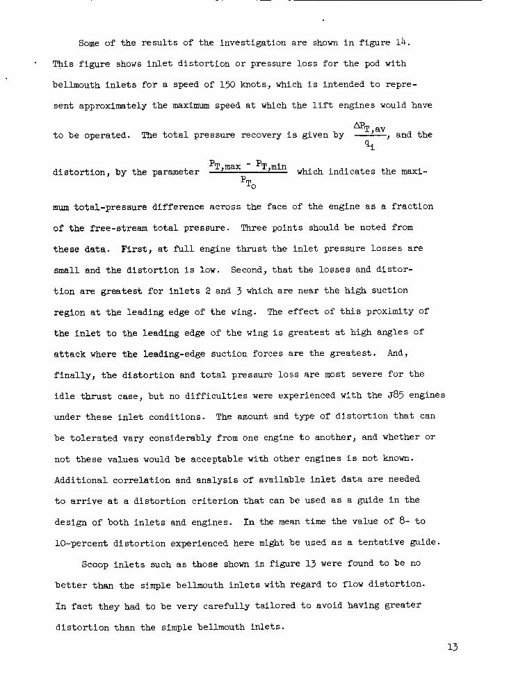
Some of t he r e s u l t s of the investigation a re shown i n f igure 14. * This f igu re shows i n l e t d i s to r t ion o r pressure lo s s f o r t he pod with
bellmouth i n l e t s f o r a speed of 150 knots, which i s intended t o repre-
sent approximately the maximum speed a t which the l i f t engines would have
, and the mT, av The t o t a l pressure recovery i s given by - Q,.
t o be operated. L
d i s to r t ion , by the parameter PTymax - PT,min which ind ica tes t he m a x i -
TO P
mum total-pressure difference across the face of the engine a s a f r ac t ion
of t he free-stream t o t a l pressure. Three points should be noted from
these data . F i r s t , a t full engine t h r u s t the i n l e t pressure losses are
small and the d i s to r t ion i s low.
t i o n a re grea tes t f o r i n l e t s 2 and 3 which a re near t he high suction
region a t t he leading edge of t he wing.
t h e i n l e t t o the leading edge of t h e wing i s grea tes t a t high angles of
a t t a c k where the leading-edge suction forces a re the grea tes t .
f i n a l l y , t h e d i s to r t ion and t o t a l pressure lo s s a re most severe f o r the
i d l e t h r u s t case, but no d i f f i c u l t i e s were experienced with the 585 engines
under these i n l e t conditions. The amount and type of d i s to r t ion t h a t can
be to l e ra t ed vary considerably from one engine t o another, and whether o r
not these values would be acceptable with other engines i s not known.
Additional cor re la t ion and ana lys i s of available i n l e t da ta are needed
t o arrive a t a d i s to r t ion c r i t e r i o n that can be used as a guide i n the
design of both i n l e t s and engines.
10-percent d i s to r t ion experienced here m i g h t be used as a t en ta t ive guide.
Second, t h a t t he lo s ses and d i s to r -
The e f f e c t of this proximity of
And,
I n the mean t i m e t he value of 8- t o
Scoop i n l e t s such as those shown i n f igure 13 were found t o be no
b e t t e r than the simple bellmouth i n l e t s with regard t o flow d i s to r t ion .
I n f a c t they had t o be very careful ly ta i lored t o avoid having grea te r
d i s t o r t i o n than the simple bellmouth in l e t s .

For simple bellmouth i n l e t s t he radius of t he upstream l i p of the
i n l e t i s a c r i t i c a l design fac tor .
t he f l o w w i l l break away from t h e l i p and give large d i s to r t ions and
pressure losses .
losses are given i n f igu re 13. A t the l e f t i n t he f igure i s shown data
on i n l e t t o t a l pressure l o s s ( r e l a t ed t o free-stream dynamic pressure)
as a function of the i n l e t ve loc i ty r a t i o (free-stream veloci ty/
veloci ty a t the face of t he engine). These data a re from a number of
d i f fe ren t sources, references 12 and 13 and unpublished data, and a r e
a l s o f o r both small-scale models and fu l l - sca l e engine in s t a l l a t ions . The
da ta show t h a t as the ve loc i ty r a t i o increases the losses rise sharply,
evidently as a r e s u l t of i n l e t l i p separation.
If the i n l e t l i p radius i s too small,
Some data showing the e f f e c t of l i p radius on pressure
The p lo t a t the r igh t i n f igure 15 i s a crossplot of t h e data a t t h e
l e f t showing the i n l e t l i p radius required t o keep the i n l e t total-pressure
losses down t o an a r b i t r a r y 20 percent of the i n l e t dynamic pressure. This
p lo t shows a rough cor re la t ion of ve loc i ty r a t i o with i n l e t radius, and
a l so shows somewhat b e t t e r performance a t model scale . T h i s l a t t e r point
i s surprising because previous experience with ducted propel ler conf igu-
ra t ions ( r e f . 14) had indicated premature l i p separation a t small scale
on the bas i s of force- tes t data. There a re several f ac to r s t h a t could
account f o r the apparently b e t t e r performance of the model i n l e t s ind i -
cated by f igu re 15. In t h e case of t he configuration of reference 13,
where a direct-model-full-scale comparison was attempted, t he survey
plane location of t h e fu l l - s ca l e configuration could not be duplicated on
t h e model because of the g rea t e r thickness of t h e model fan (ref. 15).
Thus the survey was c loser t o the i n l e t on t h e model than on the fill-
scale a r t i c l e ; and, as pointed out i n reference 12, t h i s would reduce the
i n l e t losses thus determined. Also, t he e f f e c t of t h e fan load d i s t r ibu -
t i o n i s unknown, but may be s igni f icant . The fu l l - sca l e fan had a
14
reasonably uniform r a d i a l d i s t r ibu t ion of load as compared t o the model
which was highly loaded toward the blade t i p s .
of t he t i p sections of the model fan, as compared t o the root sect ions
which experienced some reversed flow, would tend t o reduce the tendency
f o r t he flow t o separate from the walls of the duct. Also a l l the i n l e t s
were v e r t i c a l except those on the Ames 5-engine pod where the i n l e t s were
canted 10' ahead of v e r t i c a l .
differences, the data of figure 15 emphasize the importance of providing
adequate i n l e t l i p radius t o delay flow separation within the range of
ve loc i ty r a t i o s expected f o r t he airplane.
The g rea t e r effect iveness
I r respect ive of these model-full-scale
4.2. Effect of I n l e t on Engine Windmilling
Another cha rac t e r i s t i c t h a t was investigated i n the Ames tests with
t h e l i f t -engine pod was engine windmilling with various i n l e t s and a t
various angles of a t tack . Some of t he data from the invest igat ion a r e
shown i n f igure 16.
percent ra ted engine rpm) as a function of angle of a t t ack f o r the simple
bellmouth i n l e t s (with a def lec tor ahead of the e x i t of engine No. 1) and
f o r scoop i n l e t s .
qu i te unsat isfactory from the standpoint of engine windmilling with a view
toward windmill s t a r t i ng .
engine 3 windmilled i n the wrong direct ion. On the other hand, the engines
windmilled f a i r l y wel l with the scoop i n l e t s . It should be noted t h a t ,
f o r e i t h e r type of i n l e t , t he windmilling r a t e f o r engine 3 dropped of f
markedly as angle of a t t ack was increased. These cha rac t e r i s t i c s prob-
ab ly resu l ted from t h e low-pressure f i e l d on t h e top of t he wing near
t h i s i n l e t .
This f igu re shows plots of windmilling r p m ( i n
The data show t h a t the simple bellmouth i n l e t s were
Engine 4 would hardly windmill a t a l l , and
It was a l so observed during the t e s t s t h a t s t a r t i n g the engines with
e l e c t r i c starters a t 150 knots and
type of i n l e t .
a, = 8' was no problem with e i t h e r
15

5. CONCLUDING REMARKS
This paper has summarized some of t he more per t inent r e s u l t s of
some recent NASA invest igat ions re la ted t o the aerodynamics of j e t VTOL
engine in s t a l l a t ions . I n many cases these are continuing programs and
f i n a l conclusions cannot be s ta ted a t t h i s point . The most per t inent
conclusions from t h e present summary appear t o be the following:
Jet-induced base lo s s i n hovering.- The jet-induced base l o s s
encountered i n hovering out-of-ground e f f e c t i s a function of the r a t i o
of t o t a l configuration planform area t o j e t area and of the r a t e of
decay of t he j e t s . An accurate predict ion of the base losses f o r a
given configuration requires that the decay curves f o r fu l l - s ca l e engines,
with the nozzles t o be used i n the a i r c r a f t i n s t a l l ed , be known. Also,
care must be exercised i n applying base-loss increments and nozzle-
t h r u s t increments, t o see t h a t the external p a r t of t he nozzle loss i s
not accounted f o r twice i n predict ing the t o t a l system performance.
Interference e f f e c t s i n t r ans i t i on . - The jet-free-stream i n t e r -
ference e f f e c t s can cause la rge losses i n l i f t and large pi tching moments
i n the t r ans i t i on conditions. These e f f e c t s can be a l t e r ed s igni f icant ly
by proximity t o the ground; but , t he manner i n which these increments a re
a l t e r ed i s highly configuration dependent. Similar ly s ign i f icant l o s ses
i n r o l l control from react ion je ts near the wing t i p s can be encountered
a t high t r ans i t i on speeds, pa r t i cu la r ly under high s i d e s l i p conditions.
The decrease i n effect iveness can be reduced by placing the control je ts
as close t o the t r a i l i n g edge and as close t o the wing t i p as possible .
The mutual i n l e t - ex i t in te r fe rence e f f e c t s i n t r a n s i t i o n f o r l i f t - eng ine
configurations appear t o be negl ig ib le - on t h e b a s i s of very l i m i t e d
tests.
In l e t cha rac t e r i s t i c s . - Simple bellmouth i n l e t s of adequate l i p
radius (about one-half the i n l e t t h roa t diameter) give reasonably
16

high-pressure recoveries and low flow d is tor t ion throughout t he t r ans i -
t i o n range f o r l i f t engines.
t a i l o r e d t o give a s low d i s to r t ion as t h e bellmouth i n l e t s .
Scoop-type i n l e t s have t o be carefu l ly
Bellmouth
i n l e t s , even with a def lec tor ahead of the engine e x i t s , do not provide
adequate engine windmilling charac te r i s t ics f o r windmill s t a r t i n g - par t i cu la r ly a t high angles of a t tack. Scoop i n l e t s , however, can provide
sa t i s f ac to ry windmilling charac te r i s t ics .
REFERENCES
1. Rolls, L. Stewart: Jet VTOL Power Plant Experience During Fl ight Test
of X-14A VTOL Research Vehicle.
A i r Force Stat ion, Tennessee, October 25-27, 1965.
AGARD Spec ia l i s t s Meeting, Arnold
2. Gentry, Carl L., and Margason, Richard J. : Jet-Induced Losses
on VTOL Configurations Hovering I n and Out of Ground Effect .
Proposed Technical Note, 1965.
NASA
3. Wygnanski, I.: The Flow Induced by Two-Dimensional and Axisymmetric
Turbulent J e t s Issuing Normally t o an I n f i n i t e Plane Surface.
Report No. 63-12. McGill University, Montreal, Canada.
4. McLemore, Hue1 C . : Invest igat ion t o Determine the S t a t i c J e t Induced
Base Loss of a Turbojet Engine VTOL Configuration.
Technical Note, 1965.
NASA Proposed
5. Fleming, W i l l i a m A.: Charac te r i s t ics of a Hot Jet Discharge From a
Je t -Propulsion Engine. NACA RM No. E6L27a, 1946.
6. Higgins, C. C . , and Wainwright, T. W . : Dynamic Pressure and Thrust
Character is t ics of Cold Je t s Discharging from Several Exhaust Nozzles
Designed f o r VTOL Downwash Suppression. NASA TN D-2263, 1964.
7. Higgins, C. C . , Kelly, D. P., and Wainwright, T. W.: Exhaust Je t Wake
and Thrust Charac te r i s t ics of Several Nozzles Designed f o r VTOL
Downwash Suppression - Tests I n and Out of Ground Effect With 70' F
and 1200' F Nozzle Discharge Temperatures.
Report, 1965.
8. Vogler, Raymond D. :
NASA Proposed Contractor
In te r fe rence Ef fec t s of Single and Multiple Round
o r Slot ted J e t s on a VTOL Model i n Transi t ion. NASA TN D-2380, 1964.
9. W i l l i a m s , John: Aerodynamic In te r fe rence Effect of the Je t -L i f t Schemes
f o r V/STOL Aircraf t .
Station, Tennessee, October 25-27, 1965.
AGARD Spec ia l i s t s Meeting, Arnold A i r Force
18
10. Vogler, Raymond D.: Ground Effec ts on a Multiple-Jet VTOL Model a t
NASA Transi t ion Speeds Over Stat ionary and Moving Ground Planes.
Proposed Technical Note, 1965.
11. W i l l i a m s , John, and Butler , Sidney, F. J.: Further Developments i n
Low-Speed Wind-Tunnel Techniques for V/STOL and High-Lift Model
Testing. RAE Tech. Note No. Aero. 2944, January 1964.
12. Tyson, B. I.: Tests of A i r I n l e t s fo r Jet L i f t Engines. Society of
Automotive Engineers, preprint %OB, April 27-30, 1964.
13. Aoyagi, Kiyoshi, Hickey, David H., and desavigny, Richard A.: Aero-
dynamic Charac te r i s t ics of a Large-Scale Model With a High Disk-
Loading Li f t ing Fan Mounted i n the Fuselage. NASA TN D-775, 1961.
14. Grunwald, Kalman J., and Goodson, Kenneth W.: Division of Aero-
dynamic Loads on a Semispan Tilting-Ducted-Propeller Model i n
Hovering and Transi t ion F l ight . NASA TN D-1257, 1962.
15. Davenport, Edwin E., and Kuhn, Richard E.: Wind-Tunnel-Wall Ef fec ts
and Scale Ef fec t s on a VTOL Configuration With a Fan Mounted i n
the Fuselage. NASA TN D-2$0, 1-96?.
e Q n u QO n
\I- -.02
T
PLENUM I I I
1.2 1.4 1.6 1.8 20 2.2
Figure 1.- Effect of plenum chaxber configuration on base loss . S/Aj = 69.5.
-.04 112 1.4 1.6 1.8 2.0 2.2
PT
of - I I I I I
0 2 4 6 8 1 0 x/D
Figure 2.- Correlation o f base lo s
CIRCULAR PLENUM 0 SMOOTH FLOW 0 ROUGHENED FLOW
jO\ 0 L-2
RECTANGULAR PLENUM 0 ORIGINAL CONDITION A MODIFIED
s w i t h j e t decay.
Orez= ---
.p. I I I I I
HE: ~ , OSMALL COLD JET
ENGINE - AL ; ,021 O J 8 5
T -.04
~ 4 ,OSMJAELTsCOLD 0 2 4
J85 ENGINE
I I I I J 0 2 4 6 6 1 0
x / D ~
Figure 3.- Effect of jet arrangement on base loss and jet decay.
FULL SCALE (REF. 4) FULLSCALE (REF. 5)
- MODELS (FIG.2)
I I I I I I 0 2 4 6 8 IO
D X -
Figure 4.- Comparison of model jet and full-scale-engine jet decay.
I 0 CIRCULAR 8 NOZZLE
0 SINGLE SLOT NOZZLE
0 FOURSLOT NOZZLE
Figure 5.- Effect of nozzle configuration and temperature on jet decay.
0 SINGLE SLOT NOZZLE FIGURE 5 0 CIRCULAR NOZZLE
0 FOUR SLOT NOZZLE X OTHER NOZZLES
1 LOSS Cv-l. - .04
"FUSELAGE" "FUSELAGE"
0 .2 .4 .6 .8 0 .2 .4 .6 .-
TEMPERATURE a REDUCTION, (TN)
2- = 3.0 De
DYNAMIC PRESSURE REDUCTION,
Figure 6.- Thrust loss and j e t decay of suppressor nozzles.
NOZZLE INTERNAL LOSS
NOZZLE EXTERNAL
ADDITIONAL LOSS DUE TO FUSELAGE Loss I
MEASURED LOSS NOZZLE ALONE
Figure 7.- Thrust losses on in s t a l l ed nozzles.
-- T - - -4.0
-.a- 0 .I .2 .3
p. v.
u 0 .I .2 .3 E p. v?
.4
‘\. - ~ 1.0 - .4 O k 0 . I > .3
Figure 8.- Ground ef fec t on je t interference i n t r ans i t i on .
wi = ILB/SEC
CALCULATED ‘f I .5 MEASURED
INLET ALONE I MEASURED
0
- -.5 ALV T
Figure 9.- Mutual interference of i n l e t and ex i t flows.
CONTROL JETS -77 I .o
1, .5 ‘v=o
I 8 , = 0 , , , 18=30, I , 0 50 100 150 0 50 100 150
V, KNOTS V, KNOTS
Figure 10.- Effect of velocity on r o l l control f r o m t i p j e t s .
B =O" -1
0 50 100 150 0 50 100 150 V, KNOTS V, KNOTS .
Figure 11.- Effect of je t location on r o l l control.
Figure 12.- Ames five-engine pod with bellmouth i n l e t s .
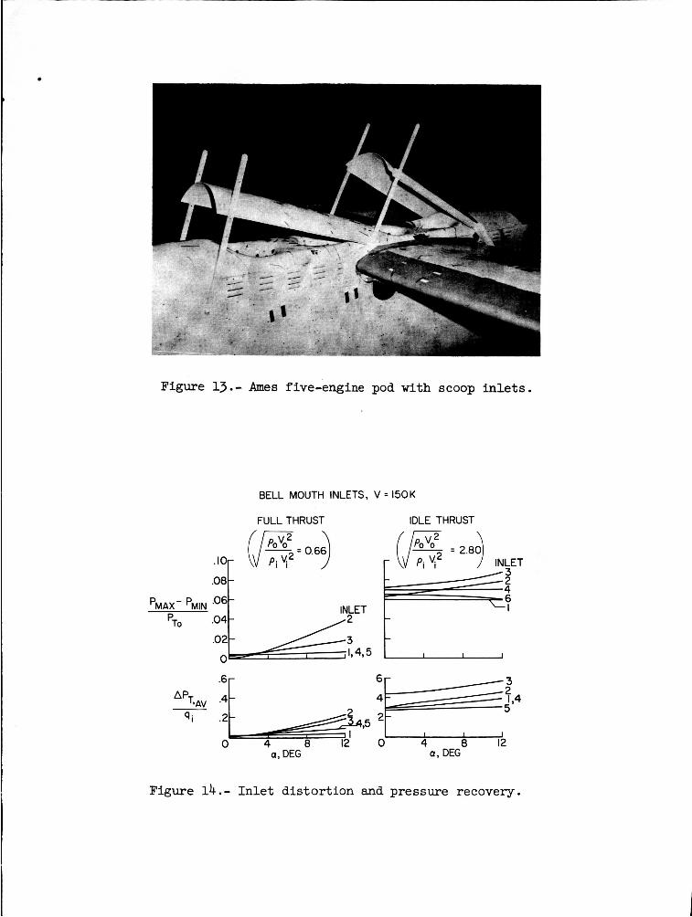
Figure 13.- Ames five-engine pod with scoop in l e t s .
BELL MOUTH INLETS, V = 1 5 0 K
FULLTHRUST IDLE THRUST
.08
%AX- PMIN pTO .04
/2 INLET t . 0 2 W ? 4 , 5 t I I I 0
qi .2 ~ ~ , 5 : r j , 4
0 4 8 12 0 4 0 12 a, DEG a , DEG
Figure 14.- In l e t dis tor t ion and pressure recovery.

.57 0.5 5J85 POD SCALE
.23 1.0 REF: I I
.23 .24MODEL OF CONFIGURATION OF REF: I I 1
A '20 .47 .5 .5 }REF: IO(M0DELS)
I.2-
.8-
4- qi
I I 0 4 - .8 1.2 1.6 2.0 2.4 0 .2 A .6
Figure 15.- Effect of inlet radius on pressure recovery.
V = 1 5 0 K
ENG I NE W I NDM I LL
70 RATED
0
4 8 12 a, DEG
0 4 8 12 a, DEG
Figure 16. - Engine windmilling characteristics.
NASA-Langley, 1965