linear measurements
TRANSCRIPT

Chapter 2
Linear measurements

Introduction
• Linear measurement means that measurement of perpendicular distance between two points or surface.
• Its applies to measurement of length,heights,diameters,thichness, radius etc.
• These instruments are designed either for line measurement or end measurement.
• Classification of linear measuring instruments
A) classification based on methods of measurement
1. Direct measuring instruments.
2. Indirect measuring instruments.
B) Classification based on the accuracy that can be obtained
1. Non precision instruments
2. Precision instruments

Non precision instruments
InsideCalipersOutside caliper
Divider caliper

Use of callipers
Precision instruments
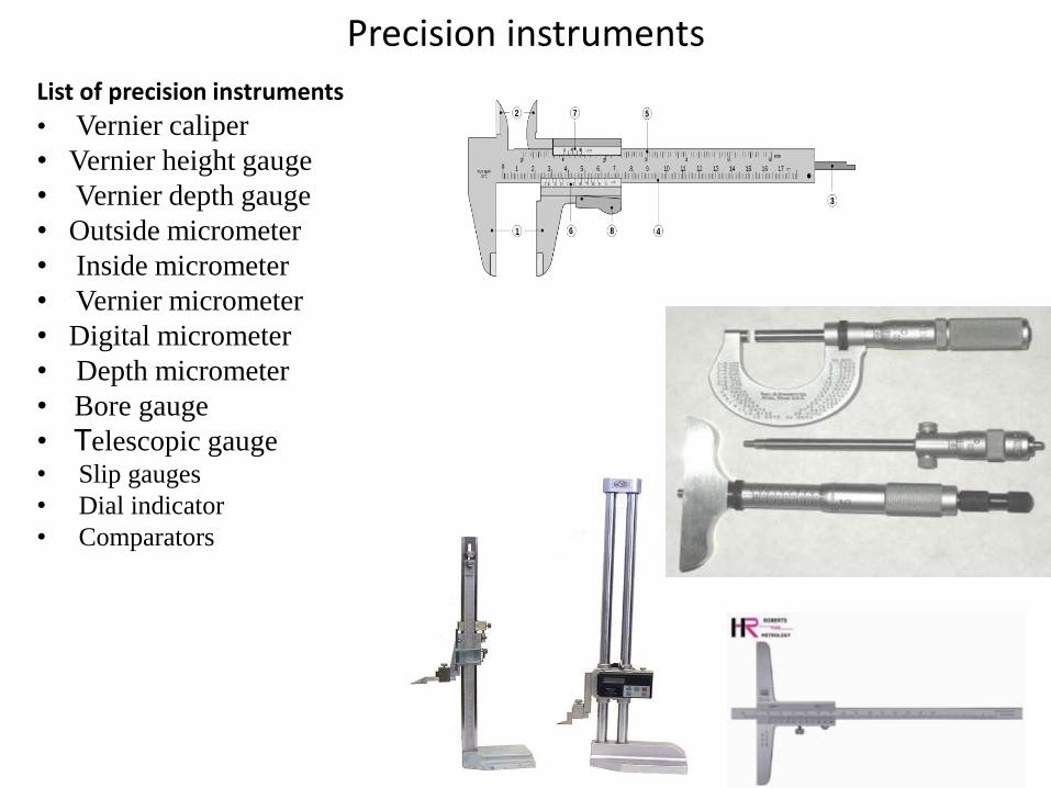
List of precision instruments
• Vernier caliper
• Vernier height gauge
• Vernier depth gauge
• Outside micrometer
• Inside micrometer
• Vernier micrometer
• Digital micrometer
• Depth micrometer
• Bore gauge
• Telescopic gauge• Slip gauges
• Dial indicator
• Comparators

Least count of vernier calliper
• It is the capability of an instrument to measure minimum distance accurately.
• The least count is the difference between the value of main scale division and auxiliary scale division.
• L.C. of vernier instruments:-
L.C = value of smallest division on main scale / no. of division on auxiliary scale
= 1 mm/10=0.1mm

Least count of micrometer
• L.C. of micrometer instruments:-
L.C = value of smallest division on main scale / no. of division on auxiliary scale
= 1 mm/50
=0.02mm

Scale
• The most common tool for crude measurements is the scale (also known as rules, or rulers)
• Although plastic, wood and other materials are used for common scales, precision scales use tempered steel alloys, with graduations scribed onto the surface.
• Parallax error can be a factor when making measurements with a scale.
If the instrument is not measured directly on,thenthere may be some error. Note: this wouldnot occur if the scale was perfectly thin.

Vernier caliper(Dec-12)Principle:-When two scales or division slightly different in size are used, the difference
between them can be utilized to enhance the accuracy of measurement.
1) Outside jaws: used to measure external diameter or width of an object
2) Inside jaws: used to measure internal diameter of an object
3) Depth probe: used to measure depths of an object or a hole
4) Main scale: scale marked every mm
5) Main scale: scale marked in inches and fractions
6) Vernier scale gives interpolated measurements to 0.1 mm or better
7) Vernier scale gives interpolated measurements in fractions of an inch
8) Retainer: used to block movable part to allow the easy transferring of a measurement

Construction
• The vernier calliper consists of two scale , one is fixed and the other is movable.
• The fixed scale called main scale is callibrated on L shaped frame and carries a fixed jaw.
• The movable sale called vernier scale and carries a movable jaw, the movable jaw as well as the fixed jaw carries measuring tip.
• When the two jaws are closed the zero of the vernier scale coincides with the zero of the main scale. For precise setting of the movable jaw an adjustment screw is provided.
• also, an arreagment is provided to lock the sliding scale on the fixed main scale.

Uses of vernier caliper
• Vernier callipers are employed for both internal and external measurment.
• It is generally used by closing the jaws on to the work surface and taking the readings from the main scale as well as the vernier scale.
Reading = M.S + V.S*(L.C)
= 23 + 20 * (0.02)
= 23 + 0.4
= 23.4mm
L.C = Value of smallest division on M.S / total division on V.S
= 1 / 50= 0.02mm

Types of vernier callipers
• According to IS:3651-1947,three types of vernier callipers have been specified to measure external and internal dimensions upto 2000 mm with least count of 0.1,0.02,0.05 and 0.01mm.
• These are available in range of :0-125mm,0-200mm.0-300 mm, 0-500mm,0-750mm,0-1000mm,750-1500mm,and 1500-2000mm.
1) Type A
2) Type B
3) Type C

A type vernier
• These type of vernier has a jaw on both sides for external and internal measurements and a blade for depth measurements as shown below.

B type vernier
This type of vernier has a single pair of jaw, one side of jaw for external and other side of jaws for internal measurments as shown below

C type vernier
• This type of vernier has a jaws both sides, one side jaws for external and internal measurements. Other side jaws is used for making operations as shown in below.

Precaution to be taken in use of vernier calliper

Errors in vernier calliper
• Errors due to play between the sliding jaw and fixed scale bar.
• Zero error due to wear and wrapping of jaws.
• Errors due to incorrect observation of scale readings
• Errors due to excessive force on moving jaw.
• Errors is also introduced if the line of measurement does not coincide with the line of the scale.

Zero error
• Before using the vernier calipers, the jaws must be closed to check if there is zero error.
• When the zero marking on the vernier scale is not in line with the zero marking on the main scale, the distance between the two markings is the zero error.

If the zero marking of the vernier scale is to the right of the zero marking on the main scale when the jaws are closed, the zero error is positive.
Zero error= 0.09 cm
0 1
0 5 10

0 1
0 5 10
If the zero marking of the vernier scale is to the left of the zero marking on the main scale when the jaws are closed, the zero error is negative.
Zero error= -0.01 cm

21
0 1
0 5 10
4 5
0 5 10
Zero error is +Ve= 0.09 cmObserved reading= 4.03 cmAccurate reading= 4.03 - 0.09 cm= 3.94 cm
Reading

22
0 1
0 5 10
4 5
0 5 10
Zero error is -Ve= -0.01 cmObserved reading= 4.03 cmAccurate reading= 4.03 - (-0.01) cm= 4.04 cm

Vernier height gauge(June 13, Nov 12)
Principle :- It works on the principle of difference
between two differently graduated scales.
Use :- Precession Marking and Measurement of
height
Parts :- 1.Base 2. Beam/Main scale 3. Fine unit
4. Scriber 5.Vernier slide 6. Locking
screws
Range :-
300mm,400mm,600mm,900mm,1200mm.(Metric)
2
5
6
3
4
1

Construction
• A finely ground and lapped base. The base is massive and robust in construction to ensure rigidity and stability.
• A vertical graduated beam or column supported on a massive base.• Attached to the beam is a sliding vernier head carrying the vernier scale
and a clamping screw.• An auxiliary head which is also attached to the beam above the sliding
vernier head. It has fine adjusting and clamping screw.• A measuring jaw or a scriber attached to the front of the sliding vernier.
Precautions• When not in use, vernier height gauge should be kept in its case.• It should be tested for straightness,squreness and parallelism of the
working faces of the beam, measuring jaw and scriber.• The springing of the measuring jaw should always be avoided.
`

Vernier height gauge

Vernier Depth gauge
Vernier depth gauge is used to measure the depths of holes , slots and recesses, to locate centre distance etc.
Construction
• A sliding head having flat and true base free from curves and waviness.
• A graduated beam known as main scale. • The sliding head slides over the
graduated beam.• An auxiliary head with a fine adjustment
and a clamping screw.

Vernier Depth gauge
Simple vernier depth gauge
Digital vernier depth gauge
Dial vernier depth gauge

Micrometer(Jun 11)Principle:- The Micrometer works on the principle of screw and nut. The linear
movement of the spindle during one rotation is equal to the pitch of
screw.
Parts:-
• Frame• Anvil• Spindle• Sleeve/Barrel• Thimble• Ratchet• LockUses :- Precision Outside linear measurement.
Range :-0-25mm, 25-50mm 50-75mm, 75-100mm etc.
Types of micrometer:-
1) Outside micrometer
2) Inside micrometer
3) Vernier micrometer
4) Depth micrometer
5) Bench micrometer
6) Digital micrometer
7) Differential micrometer
8) Micrometer with dial gauge
9) Screw thread micrometer

Construction of outside micrometer
• The micrometer requires the use of an accurate screw thread as a means of obtaining a measurement.
• The screw is attached to a spindle and is turned by movement of a thimble or ratchet at the end.
• The barrel, which is attached to the frame , acts as a nut to engage the screw threads, which are accurately made with a pitch of 0.05 mm.
• Each revolution of thimble advances the screw 0.05 mm.
• On the barrel a datum line reads in mm, and the set above the line reads in half mm.
• The thimble scale is marked in 50 equal divisions, figured in fives, so that each small division on the thimble represents 0.01mm.

Working• The thimble is rotated till the spindle touches the work piece. Then the
final adjustment is made by using ratchet.
• The locknut is then tightened and the dimension is measured on main scale and thimble scale.
0 1 2 3 4 5 6 7 8 9
151617
18
1413
19
15
17
16
1413
1815
0 1 2 3
Smallest Measurement
0.00
Largest sleeve reading
3.00
One mark past
largest sleeve
reading
0.25
Thimble Reading
0.16 * (0.01)
3.41 mm

Precautions & care(Nov 12, Jun 11)
• Clean the measuring surface of anvil before use.
• Check the instrument for zero reading before use.
• While taking measurements, pressure applied on thimble must be correct. Use ratchet for final judgment of pressure.
• Do not apply undue pressure.
Uses:-

Example 1
Reading
= M.S + (T.S. * (L.C))
= 13.5 + (13 * 0.01) mm
= 13.5 + 0.13.
= 13.63mm

Example 2
Reading
= M.S + (T.S. * (L.C))
= 7 + (31 * 0.01) mm
= 7 + 0.31
= 7.31mm

Inside micrometer
• The inside micrometer is used to measure the internal dimensions of work piece.
Construction:-
• It is similar to the outside micrometer. However inside micrometer has no U shape frame and spindle.
• The measuring tips are constituted by jaws whose faces are hardened and ground to a radius.
• The one of the jaw is held stationary at the end and second moves by the rotation of the thimble.
• The locking arrangement is provided with fixed jaw.

Inside micrometer
Another inside micrometer is used to larger internal dimension.

Uses of inside and outside micrometer

Vernier Micrometer (Dec-12,May 12)
• In order to increase accuracy , the vernier principle also be applied to outside micrometer.
• The vernier micrometer consists of three scales.
1) Main scale is graduated on barrel.2) Thimble scale is graduated on the
thimble.3) Vernier scale is marked on barrel.
Least count on vernier micrometer:-
= Value of smallest division on thimble – Value of smallest division on vernier scale.= 0.01-0.009=0.001mm

Reading of vernier micrometer
Reading 1
=MS+TS*(L.C)+VS*(L.C)=5.5 +28*(o.o1)+8*(0.001)=5.5+0.28+0.008=5.788mm

Depth micrometer(Nov 11)
• The depth gauge micrometer is aprecision measuring instrument, usedby engineers to measure depths.
• Each revolution of the rachet movesthe spindle face 0.5mm towards thebottom of the blind hole.
• The diagram shows how the depthgauge is used.
• The ratchet is turned clockwise untilthe spindle face touches the bottom ofthe blind hole.
• The scales are read in exactly the sameway as the scales of a normalmicrometer.

Working of depth gauge

Bench Micrometer
• A bench micrometer is a high precision micrometer with an anvil retractor device for repeated measurement.
• The worktable is adjustable and the indicator can measure up to 1 µm.
• The Anvil pressure is adjustable and linear friction transfer mechanism is used between anvil and indicator for high accuracy.

Digital micrometer
• The digital micrometers are available in a large amount of different sizes, normally 0 25 mm,25 – 50mm , 50-75mm ,and 75-100mm.
• They are used to measure length , diameter or thickness.

Screw Thread Micrometer
• The shape of a Screw thread Micrometer is more or less like an ordinary micrometer with the difference that it is equipped with a pointed spindle and a double V-anvil, both correctly shaped to contact the screw thread of the work to be gauged.
• The angle of the V-anvil and the conical point at the end of the spindle correspond to the included angle of the profile of the thread.
• The extreme point of the cone is rounded so that it will not bear on the root diameter at the bottom of the thread, and similarly clearance is provided at the bottom of the groove in the V-anvil so that it will not bear on the thread crest.
• The spindle point of such a micrometer can be applied to the thread of any pitch provided the form or included angle is always same.

Micrometer with dial gauge

Differential micrometer
• A very high degree of accuracy can be obtained in the micrometer screw gauges utilising the principle of differential screw on the operating spindle.
• The screw has two types of pitches, one smaller and one larger, instead of one uniform pitch as in conventional micrometer.
• Both the screws are right-handed and the screws are so arranged that the rotation of the thimble member moves one forward and the other backward.
• If the larger screw has a pitch of 1.25 mm and smaller screw of 1.00 mm pitch,, then the net result would be a total forward movement of 1.25-1.00 =0.25 mm per revolution.
• Thus if thimble has 100 divisions and vernier scale be engraved on the sleeve, then the least count of the instrument
=0.25×1 ∕100×1∕10=0.00025 mm.
• It will be noted that this will have appreciably smaller total range of linear movement, although the main spindle’s travel is larger. This is because the main spindle which is attached to the moving portion gets only differential movement.
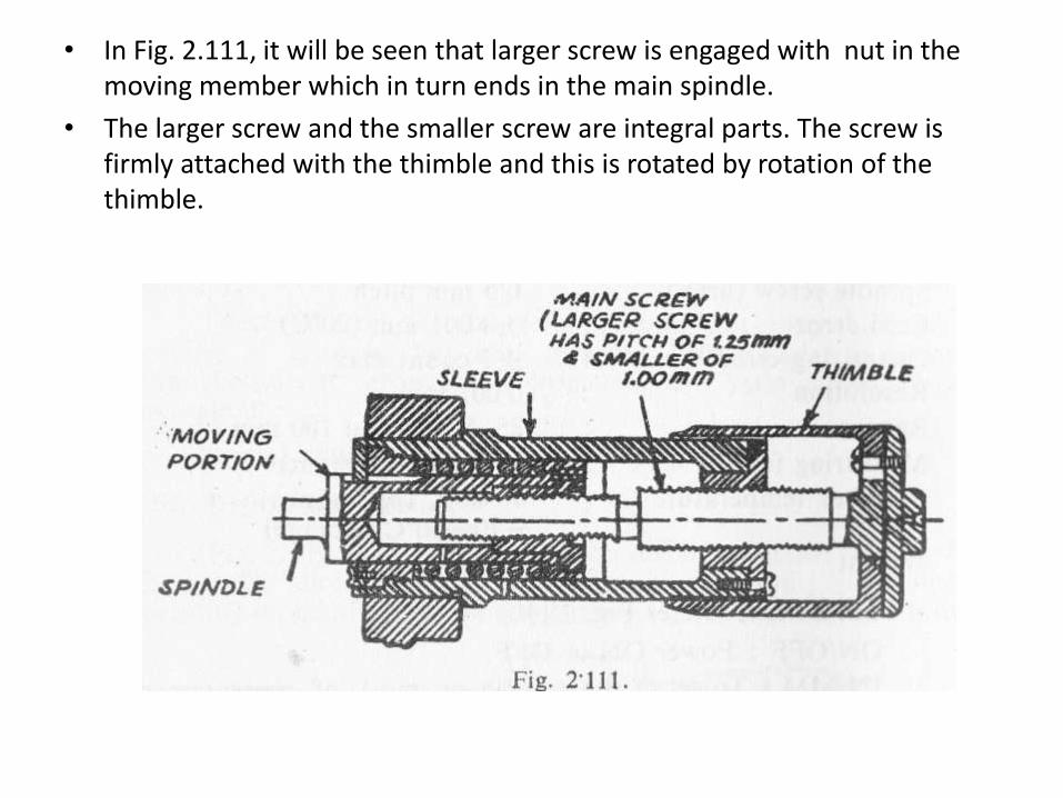
• In Fig. 2.111, it will be seen that larger screw is engaged with nut in the moving member which in turn ends in the main spindle.
• The larger screw and the smaller screw are integral parts. The screw is firmly attached with the thimble and this is rotated by rotation of the thimble.

Micrometer Don’ts
• Do not drop
• Do not run over
• Do not over tighten (it is not a vice)
• Do not drop in chemicals
• Do not leave it covered in grease
• Do not let anyone borrow it
• Do not leave lying around

DIGITAL DEPTH MICROMETER
DIGITAL DEPTH MICROMETER

Micrometer Do’s
• Keep clean
• Keep calibrated
• Keep in storage box
• Keep locked up
• Keep away from everyone
• Keep in practice reading it !

Exercises
Red = 3.05mm Red = 3.25mm
Red = 6.95mm


Exercises
Red = 3.75mm
Red = 7.90 mm
Red = 3.85mm

Exercises
1. Red = 7.36 ……………………..(L.C = 0.01)
2. Red = 4.78
3. Red = 6.82
4. Red = 1.29
5. Red = 9.77
6. Red = 2.56
7. Red = 1.49

Exercises

Bore gauges
Principle: Linear motion of Plunger is converted into magnified rotary motion
of Dial.
Use :- Precision bore measurement and Ovality checking.
Parts :-
1. Stem
2. Fix anvil
3. Sliding plunger
4. Centering shoes
5. Dial indicator
Range :- 0-10mm
Types:-
1) Dial bore gauge
2) Hemispherical bore gauge
5
1
3
4
2

Dial bore gauge
Construction:-
• The measuring body is connected with dial indicator body by tube.
• The push rod is provided inside the tube in order to transmit the movement of movable measuring head to dial indicator.
• Hence the horizontal movement of the rod is transmitted into vertical direction and dial indicator which gives indication of variation of size.
• Accuracy of this bore gauge is 0.001mm.

Dial bore gauge
A dial bore gauge is an expensive, but important, gauge used to measure cylinder taper and out-of-round as well as main bearing (block housing) bore for taper and out-of-round
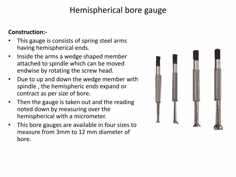
Hemispherical bore gauge
Construction:-
• This gauge is consists of spring steel arms having hemispherical ends.
• Inside the arms a wedge shaped member attached to spindle which can be moved endwise by rotating the screw head.
• Due to up and down the wedge member with spindle , the hemispheric ends expand or contract as per size of bore.
• Then the gauge is taken out and the reading noted down by measuring over the hemispherical with a micrometer.
• This bore gauges are available in four sizes to measure from 3mm to 12 mm diameter of bore.


Uses of bore gauge

Telescopic gauge(Nov-11, June-10)
Use :- Indirect measurement of Bore, Slot, Recesses, etc. Used in accordance
with micrometer / Vernier.
Parts :-
1. Handle
2. Pair of Plunger
3. Lock
Construction:-
• It consists of handle, two telescopic rods & locking screw.
• One end of handle is connected with tube in which telescopic rods slides which has spherical contacts & it is forced by internal spring. For taking measurement, telescopic rods are compressed against spring & inserted into the hole whose diameter to be measured.
• Then extended up to the walls of hole.
• Then they locked by locking screw & rods can be measured by micrometer or vernier calliper. This is use in measure the diameter of IC Engines.
1
3
2

Telescopic Gauges

Slip gauges
• Slip gauges are rectangular blocks of steel having cross section of 30 mm face length & 10 mm face width as shown in fig.
• Slip gauges are blocks of steel that have been hardened and stabilized by heat treatment.
• They are ground and lapped to size to very high standards of accuracy and surface finish.
• A gauge block (also known Johansson gauge, slip gauge, or Jo block) is a precision
• length measuring standard consisting of a ground and lapped metal or ceramic block. Slip
• gauges were invented in 1896 by Swedish machinist Carl Edward Johansson.

Manufacture of Slip Gauges
• When correctly cleaned and wrung together, the individual slip gauges adhere to each other by molecular attraction and, if left like this for too long, a partial cold weld will take place.
• If this is allowed to occur, the gauging surface will be irreparable after use, hence the gauges should be separated carefully by sliding them apart.
• They should then be cleaned, smeared with petroleum jelly (Vaseline) and returned to their case.

Classification
• AA slip gauges
• A slip gauges and
• B slip gauges

• AA slip gauges– Master slip gauges
– Accurate to plus or minus two microns per meter
• A slip gauges– Reference purpose
– Type A is guaranteed accurate up to plus or minus four microns per meter
• B slip gauges– Working slip gauges
– Type 'B' for plus or minus eight microns per meter

INDIAN STANDARD ON SLIP GAUGES (IS 2984-1966)
• Slip gauges are graded according to their accuracy as Grade 0, Grade I & Grade II.
• Grade II is intended for use in workshops during actual production of components, tools & gauges.
• Grade I is of higher accuracy for use in inspection departments.
• Grade 0 is used in laboratories and standard rooms for periodic calibration of Grade I & Grade II gauges.

set of slip gaugesM-87 set of slip gauges
M-112 set of slip gauges

Protector Slips
• In addition, some sets also contain protector slips that are 2.50mm thick and are made from a hard, wear resistant material such as tungsten carbide.
• These are added to the ends of the slip gauge stack to protect the other gauge blocks from wear.
• Allowance must be made of the thickness of the protector slips when they are used.

Wringing of Slip Gauges
• Slip gauges are wrung together to give a stack of the required dimension. In order to achieve the maximum accuracy the following precautions must be taken.
• Use the minimum number of blocks.
• Wipe the measuring faces clean using soft clean chamois leather.
• Wring the individual blocks together by first pressing at right angles, sliding & then twisting.

Wringing Gage Blocks Together

Wringing of Slip Gauges
• It depends on the surface finish and flatness of the blocks used and absence of dirt, grease, burrs and scratches.
• When it correctly wrung together, the error in total length is negligible.

Important notes on building of Slip Gauges
• Always start with the last decimal place.
• Then take the subsequent decimal places.
• Minimum number of slip gauges should be used by selecting the largest possible block in each step.
• If in case protector slips are used, first deduct their thickness from the require dimension then proceed as per above order.

Numerical problem-1
Build the following dimensions using M-87 set. (i) 49.3825 mm (ii) 87.3215mm
Solution:
(i) To build 49.3825 mm
Combination of slips; 40+6+1.38+1.002+1.0005 = 49.3825 mm

(ii) To build 87.3215 mm
Combination of slips; 80+4+1.32+1.001+1.0005 = 87.3215 mm

Numerical problem-2
Build up a length of 35.4875 mm using M112 set. Use two protector slips of 2.5 mm each.
Solution
Combination of slips; 2.5+25+2+1.48+1.007+1.0005+2.5 = 35.4875 mm

Application
• They are used to check the accuracy of vernier, micrometer, and other devices.
• They are used to set the comparator to a specific dimension.
• They are used for direct measurement where the accuracy of work piece is important.
• They are frequently used with sine bar to measure angle of work piece.
• They can be used for check gap between parallel location.

Plain gauges
• Basic dimension: exact size of part from which all limiting variations made
• Limits: maximum and minimum dimensions
• Tolerance: permissible variation of part
– unilateral: one direction only
– Bilateral: both plus and minus (two directions)
• Allowance: intentional difference in dimensions of mating parts
• Gauges are inspection tools which serve to check the dimension of the manufacture parts.
• Classification of gauges
1. Standard gauges:- If a gauge is made as an exact copy of the mating part of the component to be checked.
2. Limit gauges:- These are GO and NO GO gauges.
Go gauges:- Gauges ckeck the Minimum Metal Limit(MML)
NO GO :- Gauges ckeck the Least Metal Limit(LML)

Standard gauges• A feeler gauge (also known as a thickness gauge) is an accurately
manufactured strip of metal that is used to determine the gap or clearance between two components.
• Application:-A feeler gauge can be used to check the following:
– Piston ring gap
– Piston ring side clearance
– Connecting rod side clearance

• Radius Gauge:- A radius gauge is a tool used to measure the radius of an object
• Thread Pitch Gauge:-It used to quickly determine the pitch of various threads by matching the teeth on the leaves with teeth on the work.

Limit gauges
• Basic Concept:-• It should be design to check maximum and minimum material limits.
• The terms minimum metal condition and maximum metal condition are used to describe the tolerance state of a work piece.
• Go gauge:- it is made near the maximum metal condition. It is made for checking the GO limit of the work piece and this gauge must perfectly assemble with the work piece to be inspected.
• NO GO gauges:- It is made near the minimum metal condition.

Types of limit gauges
• Plug gauges:- Plug gauges are used for checking holes and consists of two cylindrical wear resistant plugs.
• The plug made to the lower limit of the hole is known as GO end and this will enter any hole which is not smaller than the lower limit allowed.

Taper Plug Gauges
• Used to check size of hole and taper accuracy
• Made with standard or special tapers
• Some have "go" and "no-go" rings scribed gauge fits into hole between two rings means within required tolerance

Thread Plug Gauges• Used for checking internal threads of the "go" and "no-go"
variety
• Based on same principle as cylindrical plug gauges
• "go" end (longer end)
– Should be turned in flush to bottom of hole
• "no-go" end
– Should just start into hole and become snug before third thread enters

Ring gauges• IT is used for checking diameter of shaft.
• Used to check outside diameter of pieces
• Ground and lapped internally to desired size
– Size stamped on side of gauge
• Outside diameter knurled and "no-go" end identified by annular groove on knurled surface
• Precautions and procedures similar to those outlined for a plug gauge.

Snap Gauges• One of most common types of comparative measuring
instruments
• Faster to use than micrometers
• Limited in their application
• Used to check diameters within certain limits by comparing part size to preset dimension of snap gauge

Snap Gauges
• These are used for checking external dimensions.
• They are also called as gap gauges.
• A snap gauges usually consists of a plate or frame with a parallel faced gap of the required dimension.
• Snap gauges can be used for both cylindrical as well as non cylindrical work as compared to ring gauges which are conveniently used only for cylindrical.

Comparators
• Mechanical comparators
• Electrical comparators
• Optical comparators
• Pneumatic comparators

Definition
Comparator is a device which
(1) Picks up small variations in dimensions.
(2) Magnifies it.
(3) Displays it by using indicating devices, by
which comparison can be made with some
standard value.
Classification
• Mechanical Comparator: It works on gears
pinions, linkages, levers, springs etc.
• Pneumatic Comparator: Pneumatic comparator
works by using high pressure air, valves, back
pressure etc.
• Optical Comparator: Optical comparator works
by using lens, mirrors, light source etc.

Cont…………
• Electrical Comparator: Works by using step
up, step down transformers.
• Electronic Comparator: It works by using
amplifier, digital signal etc.
• Combined Comparator: The combination of
any two of the above types can give the best
result.

• Corresponds to a spindle movement of 1 mm.
• The large dial scale is graduated into 100 divisions.
• The indicator is set to zero by the use of slip gaugesrepresenting the basic size of part.
• These instruments cannot give the direct reading of the sizeslike micrometers and vernier callipers.
• Dial test indicators are instruments of high precision,
used for comparing and determining the variation in the sizesof a component.

Dial Indicator
Principle:-
• It operates on the principle, that a veryslight upward pressure on the spindle atthe contact point is multiplied through asystem of gears and levers.
• It is indicated on the face of the dial by adial finger.
Construction:
• Dial indicators basically consists of a bodywith a round graduated dial and a contactpoint connected with a spiral or gear trainso that hand on the dial face indicates theamount of movement of the contact point.
Lock screw
Main dial
Small dial
Plunger/styulus

Mechanism of dial indicator

Digital dial indicator

Application of Dial Indicator
• Determine the error in geometrical forms, e.g. ovality out of roundness, taper etc.
• Taking accurate measurements of deformation in tension and comparison testing of material.
• Comparing to heights or distance between narrow limits.
• To compare the dimensions of a work piece against a known standard, eg. slip gauges.
• To check plane surfaces for parallelism and flatness.
• To check parallelism of shafts and bars.
• To check concentricity of holes and shafts.

Advantages
• Main advantages of dial indicator are easy to use and less expensive compared to other linear measuring instruments which is require considerable skill and practice in their use.
• The feel or judgment of the operator is completely avoided using dial gauge. Once the dial indicator has been set up an unskilled operator can use it with ease and accuracy.

Dial Indicator with Stand

Application
• To check alignment of lathe centers by using a suitable accurate bar between centre


Very useful instrument for checking Steering and Suspension components


Comparators
• Comparators are the instruments calibrated by means of end standards to measure unknown dimensions.
• The purpose of a comparator is to detect and display the small differences between the unknown linear dimensions and the length of the standard.
• The difference in lengths is detected as a displacement of a sensing probe.
• The important and essential function of the instruments is to magnify or amplify the small input displacement so that it is displayed on an analogscale.
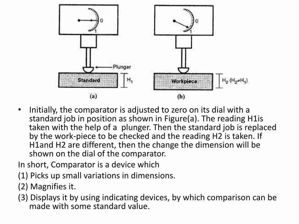
• Initially, the comparator is adjusted to zero on its dial with a standard job in position as shown in Figure(a). The reading H1is taken with the help of a plunger. Then the standard job is replaced by the work-piece to be checked and the reading H2 is taken. If H1and H2 are different, then the change the dimension will be shown on the dial of the comparator.
In short, Comparator is a device which(1) Picks up small variations in dimensions.(2) Magnifies it.(3) Displays it by using indicating devices, by which comparison can be
made with some standard value.

Classification
1. Mechanical Comparator: It works on gears pinions, linkages, levers, springs etc.
2. Pneumatic Comparator: Pneumatic comparator works by using high pressure air, valves, back pressure etc.
3. Optical Comparator: Optical comparator works by using lens, mirrors, light source etc.
4. Electrical Comparator: Works by using step up, step down transformers.
5. Electronic Comparator: It works by using amplifier, digital signal etc.

Characteristics of Good Comparators
1. It should be compact.2. It should be easy to handle.3. It should give quick response or quick result.4. It should be reliable, while in use.5. There should be no effects of environment on the comparator.6. Its weight must be less.7. It must be cheaper.8. It must be easily available in the market.9. It should be sensitive as per the requirement.10. The design should be robust.11. It should be linear in scale so that it is easy to read and get uniform
response.12. It should have less maintenance.13. It should have hard contact point, with long life.14. It should be free from backlash and wear.

Application of comparators
• The comparators are used to check the parts in mass production at a very fast rate.
• They are used to inspect newly purchased gauges.
• They are used to final inspection gauges in selective assembly of parts where parts are graded in three groups depending upon their tolerance.
• They are used for checking parts receiving from outside source .

Mechanical Comparator

Johansson MikrokatorThis comparator was developed by C.F. Johansson.
Principle:
It works on the principle of a Button spring, spinning on a loop of string like in the
case of Children’s toys.
Construction:
• The method of mechanical magnification is shown in Figure. It employs a
twisted metal strip.
• Any pull on the strip causes the centre of the strip to rotate.
• A very light pointer made of glass tube is attached to the centre of the twisted
metal strip.
• The measuring plunger is on the slit washer and transmits its motion
through the bell crank lever to the twisted metal strip.
• The other end of the twisted metal strip is fastened to the cantilever strip.
• The overhanging length of the cantilever strip can be varied to adjust the
magnification of the instrument.
• The longer the length of the cantilever, the more it will deflect under the pull of
the twisted metal strip and less rotation of the pointer is obtained.


working
• When the plunger moves by a small distance in upward direction the bell crank lever turns to the right hand side.
• This exerts a force on the twisted strip and it causes a change in its length by making it further twist or untwist.
• Hence the pointer at the centre rotates by some amount.
• Magnification up to 5000X can be obtained by this comparator.

Advantages of Mechanical Comparator
• They do not require any external source of energy.
• These are cheaper and portable.
• These are of robust construction and compact design.
• The simple linear scales are easy to read.
• These are unaffected by variations due to external source of energy such air, electricity etc.
Disadvantages• Range is limited as the pointer moves over a fixed scale.
• Pointer scale system used can cause parallax error.
• There are number of moving parts which create problems due to friction, and ultimately the accuracy is less.
• The instrument may become sensitive to vibration due to high inertia.

Mechanical (Reed) Comparator


Sigma Comparator• The plunger is attached to a bar which is supported between
the bending plates at the top and bottom portion as shown in Figure
• The bar is restricted to move in the vertical direction.
• A knife edge is fixed to the bar.
• The knife edge is attached to the sapphire plate which is attached to the moving block.
• The knife edge extorts a force on the moving block through sapphire plate.


• Moving block is attached to the fixed block with the help of
crossed strips as shown in Figure (b).
• When the force is applied on the moving block, it will give
an angular deflection.
• A Y-arm which is attached to the moving block transmits
the rotary motion to the driving drum of radius r.
• This deflects the pointer and then the reading is noted.

Mechanical - Optical Comparator
Principle:• In mechanical optical comparator, small variation in the plunger
movement is magnified: first by mechanical system and then by optical system.
Construction:• The movement of the plunger is magnified by the mechanical system using
a pivoted lever. From the Figure the mechanical magnification = x2 / x1.
• High optical magnification is possible with a small movement of the mirror.
• The important factor is that the mirror used is of front reflection type only.
• The back reflection type mirror will give two reflected images as shown in Figure, hence the exact reflected image cannot be identified.

Advantages
• These Comparators are almost weightless and have less number of moving parts, due to this there is less wear and hence lessfriction.70
• Higher range even at high magnification is possible as the scale moves past the index.
• The scale can be made to move past a datum line and without having any parallax errors.
• They are used to magnify parts of very small size and of complex configuration such as intricate grooves, radii or steps

Disadvantages
• The accuracy of measurement is limited to 0.001 mm
• They have their own built in illuminating device which tends to heat the instrument.
• Electrical supply is required.
• Eyepiece type instrument may cause strain on the operator.
• Projection type instruments occupy large space and they are expensive.
• When the scale is projected on a screen, then it is essential to take the instrument to a dark room in order to take the readings easily.

Electrical Comparators
• Electrical comparators give a wide range of advantages. As we know, components like levers, gears, racks and pinions, activate mechanical devices.
• The accuracy and life of the instruments are affected as they are subjected to wear and friction


• Electrical comparators have no moving parts. Thus a high degree of reliability is expected from these instruments.
• Generally there are two important applications of electrical comparators:
1. Used as measuring heads
2. Used for electrical gauging heads,
• To provide usual indication to check the dimensions within the limits laid down.
• The first application is very important when there is a requirement for precise
• measurement for e.g. Checking or comparison of workshop slip gauges against
• inspection slip gauges.
• The second application is used to indicate with a green light if a dimension is within the limits.
• A red lamp indicates an undersize dimension; a yellow lamp indicates an oversize dimension.
• So the operator is not required to be aware of the actual tolerances on the
dimension.
• After setting the instrument correctly, all that needs to be done is to place the
component under the plunger of the gauging head.
• The signal lamps provide in standard positive indication of the acceptability of the dimension under test
Advantages
• Measuring units can be remote from indicating units.
• Variable sensitivity which can be adjusted as per requirement.
• No moving parts, hence it can retain accuracy over long periods.
• Higher magnification is possible as compared to mechanical comparator.
• Compact sizes of probes arc available.

Disadvantages
• The accuracy of working of these comparators is likely to be affect due to temperature and humidity.
• It is not a self contained unit; it needs stabilized power supply for its operation.
• Heating of coils can cause zero drifts and it may alter calibration.
• It is more expensive than mechanical comparator

Pneumatic Comparators
Principle• It works on the principle of pressure difference generated by
the air flow.
• Air is supplied at constant pressure through the orifice and the air escapes in the form of jets
• through a restricted space which exerts a back pressure.
• The variation in the back pressure is then used to find the dimensions of a component.

Working• As shown in Figure (a) the air is compressed in the compressor at high
pressure which is equal to Water head H.
• The excess air escapes in the form of bubbles. Then the metric amount of air is passed through the orifice at the constant pressure.
• Due to restricted area, at A1 position, the back pressure is generated by the head of water displaced in the manometer
tube.
• To determine the roundness of the job, the job is rotated along the jet axis, if no variation in the pressure reading is obtained then we can say that the job is perfectly circular at position A1.
• Then the same procedure is repeated at various positions A2, A3, A4, position and variation in the pressure reading is found out. Also the diameter is measured at position A1 corresponding to the portion against two jets and diameter is also measured at various position along the length of the bore


• Any variation in the dimension changes the value of h, e.g. Change in dimension of
• 0.002 mm changes the value of h from 3 to 20 mm. Moderate and constant supply pressure is
• required to have the high sensitivity of the instrument.

Advantages
• It is cheaper, simple to operate and the cost is low.• It is free from mechanical hysteresis and wear.• The magnification can be obtained as high as 10,000 X.• The gauging member is not in direct contact with the
work.• Indicating and measuring is done at two different
places.• Tapers and ovality can be easily detected.• The method is self cleaning due to continuous flow of
air through the jets and this makes the method ideal to be used on shop floor for online controls.

Disadvantages
• They are very sensitive to temperature and humidity changes.
• The accuracy may be influenced by the surface roughness of the component being checked.
• Different gauging heads are needed for different jobs.
• Auxiliary equipments such as air filters, pressure gauges and regulators are needed.
• Non-uniformity of scale is a peculiar aspect of air gauging as the variation of back pressure is linear, over only a small range of the orifice size variation.