lincoln laboratory - defense technical information center · and optical space communication...
TRANSCRIPT

I SI l-TR-71-269
C s
A Copy No. / of _cys-
TICN DIVISION
(TRI), Building 1210
Technical Note 1971-43
Topics in Millimeter-Wave
and Optical Space Communication
Prepared under FMectronic Systems Division Contract F19628-70-C-0230 by
Lincoln Laboratory MASSACHUSETTS INSTITUTE OF TECHNOLOGY
Lexington, Massachusetts
W. W. Ward
S. L. Zolnay
16 September 1971
Pfrctf*535'

Approved for public release; distribution unlimited.

MASSACHUSETTS INSTITUTE OF TECHNOLOGY
LINCOLN LABORATORY
TOPICS IN MILLIMETER-WAVE
AND OPTICAL SPACE COMMUNICATION
W. W. WARD
Group 65
S. L. ZOLNAY
Group 63
TECHNICAL NOTE 1971-43
16 SEPTEMBER 1971
Approved for public release; distribution unlimited.
LEXINGTON MASSACHUSETTS

The work reported in this document was performed at Lincoln Laboratory, a center for research operated by Massachusetts Institute of Technology, with the support of the Department of the Air Force under Contract F19628-70-C-0230.
This report may be reproduced to satisfy needs of U.S. Government agencies.
11

ABSTRACT
Many comparative studies have been made of millimeter-wave
and optical space-communication systems. The applications
considered have been diverse, including links between satel-
lites in low Earth orbits, satellites in synchronous orbits,
deep-space probes, and Earth terminals, with data-rate re-
quirements from a few bit/sec to Gbit/sec. We present in
this report not just another such comparison, but rather a
short tutorial account of the common and of the distinctly dif-
ferent features of some millimeter-wave and optical space-
communication systems. For example, the design of the
transmitting antennas is governed by the same electromag-
netic theory, which accounts for diffraction at an aperture.
However, the signal-to-noise relationships in the receivers
may not be the same (Gaussian vs Poisson noise statistics).
Possible satellite applications are surveyed briefly, with men-
tion of the favorable and the unfavorable factors associated
with millimeter-wave and optical space-communication sys-
tems. Candidate systems are postulated and link calculations
are given.
Accepted for the Air Force Joseph R. Waterman, Lt. Col., USAF Chief, Lincoln Laboratory Project Office
111

CONTENTS
Abstract iii
I. INTRODUCTION 1
II. MILLIMETER-WAVE SPACE COMMUNICATION 2
A. Millimeter-Wave Frequency Allocations 2
B. Millimeter-Wave Propagation Phenomena 3
C. Millimeter-Wave Systems 3
D. Millimeter-Wave Technology 7
III. OPTICAL SPACE COMMUNICATION 12
A. Optical Propagation Phenomena 12
B. Optical Systems and Technology 13
IV. SOME POINTS OF COMPARISON 15
A. Noise Statistics and Detection 17
B. Antennas 19
C. Practical Factors 20
V. APPLICATIONS 21
A. Wide-Band/High-Data-Rate Systems 21
B. Narrow-Band/Low-Data-Rate Systems 25
C. Historical Note 25
VI. SUMMARY AND CONCLUSIONS 25
References 27

GLOSSARY OF ACRONYMS AND ABBREVIATIONS
CONUS Continental United States of America
DCA Defense Communications Agency
DoD Department of Defense
DSIF Deep-Space Instrumentation Facility
EHF Extremely-High Frequency, 30-300GHz
EIRP Effective Isotropically Radiated Power
EOS Earth Observational Satellite
ERTS Earth Resources Technology Satellite
IMPATT Impact Ionization Avalanche Transit Time
INTELSAT International Telecommunications Satellite Consortium
IR Infra-Red, the optical spectrum in the approxi- mate range 0.7-lOOfim
LSA Limited Space-Charge Accumulation
NASA National Aeronautics and Space Administration
Near-IR the optical spectrum in the approximate range 700-2000nm (0.7-2(j.m)
-9 S nm nanometer (10 meter). 1 nanometer = 10 A.ngstrom
PCM Pulse-Code Modulation
PIN Positive Intrinsic Negative
SHF Super-High Frequency, 3-30 GHz
TDRSS Tracking and Data-Relay Satellite System
TWTA Traveling-Wave-Tube Amplifier
V-band 50-75GHz
Visible the optical spectrum in the approximate range 400-700nm (0.4-0.7 |J.m)
WARC/ST World Administrative Radio Conference on Space Telecommunications
X-band 6.20-1 0.90 GHz
|jim micrometer (10 meter). 1 micrometer = 1000 nanometer
\'i

TOPICS IN MILLIMETER-WAVE
AND OPTICAL SPACE COMMUNICATION
I. INTRODUCTION
Back in 1961, Bob Hansen (Ref. 1) told how to write a series of versions
of a famous paper that might be entitled "Optimum Frequencies for Space
Communications." Hansen1 s recommended procedure was both simple and
speedy. Each aspiring author had only to manipulate the standard range equa-
tion using off-the-top-of-the-head guesses about antenna-gain restrictions,
vehicle weight/power restrictions, capabilities of transmitting tubes and de-
vices, and antenna-noise-temperature characteristics. Provided no one else
had used exactly the same boundary conditions (including the assumed modula-
tion format), the author could generate his own contribution to the professional
literature in about 12 hours.
Hansen1 s famous paper could be counted on in 1961 to yield optimum fre-
quencies in the range 1 to 10 GHz, with a maximum likelihood in the vicinity
of 3 GHz. Nowadays, advances in the state-of-the-art — coupled with extra-
ordinary growth in the projected data-rate appetites of the users —make it
possible for the optimum frequencies to come out in the high microwave re-
gion, or even in the optical domain. In writing this report, we have explicitly
tried to avoid writing yet another of Hansen's famous papers. The reader will
search here in vain for an unequivocal statement of the optimized superiority
of millimeter-wave over optical space communication, or vice versa. What
he will find is a short presentation of the common and of the distinctly different
features of some millimeter-wave and optical space-communication systems.
There is nothing mysterious or magical about either frequency range. Most
of the basic concepts of electromagnetic communication at much longer wave-
lengths apply in these novel domains. The few familiar basic concepts that do
not apply here can be replaced by others that will become equally conventional
in time.
Any reader who needs to go deeper into the subjects of this paper will find
a large literature awaiting him. Our bibliography is by no means exhaustive,

but it should give useful leads. Omission of any particular book, paper, or
report from it does not imply that we consider that contribution to be just an-
other version of Hansen's famous paper. Several professional periodicals
have published recent special issues devoted to millimeter-wave technology
(Refs.2-3), optical communication (Ref. 4), and satellite communications
(Ref. 5). There are many books on conventional microwave space communica-
tion (Ref. 6, for example); the number of books on optical communication
(Refs. 7-8, for example) is growing rapidly. The literature of expository re-
ports and journal articles on millimeter-wave and optical space communication
is already large (Refs. 9-23, for example).
II. MILLIMETER-WAVE SPACE COMMUNICATION
There are several motivations for moving to higher frequencies as new
demands for communication arise. In the busier parts of the world, where
demands are growing, the electromagnetic spectrum for cm-and-longer wave-
lengths has already been completely allocated and is relatively crowded by
users in the popular bands. The technology of equipment development there
is rather mature, so order-of-magnitude improvements in system performance
(or reductions in system cost) are not likely. On the other hand, going to mm-
and-shorter wavelengths appears at first sight to be very attractive; there are
vast stretches of little-used spectrum and appealing possible economies. The
greater directivity attainable — in principle — with a fixed-aperture antenna at
higher frequency allows increasing dramatically the effective isotropically
radiated power (EIRP) of a terminal for a given transmit power, with corre-
sponding system improvement (we will see below that the narrower antenna
beam can present some troublesome problems, however). Furthermore, the
millimeter-wave technology (and even more so the optical technology) is new,
different, and exciting.
A. Millimeter-Wave Frequency Allocations
During the summer of 1971, the World Administrative Radio Conference
on Space Telecommunications met in Geneva to act on proposed and recom-
mended frequency allocations. The resultant allocations in the millimeter-wave
region are listed in Table I through the courtesy of Dr. R. K. Crane, Lincoln
Laboratory, one of the US representatives to the Conference. As can be seen,
these frequency allocations cover a total bandwidth in excess of 100 GHz. The
most significant ones for immediate and near-future utilization are probably
those below 100 GHz, since this is the region where the millimeter-wave tech-
nology development is most advanced. For the purposes of this report, the
allocations in the oxygen-absorption region are of particular interest for inter-
satellite (cross-link) applications.
B. Millimeter-Wave Propagation Phenomena
The millimeter-wave bands currently proposed for space communication
suffer from adverse propagation effects in traversing the atmosphere. These
effects arise from molecular absorption by atmospheric gases — principally
oxygen — and by water vapor, from scattering by hydrometeors, and from re-
fraction and scattering by spatial variations in the refractive index. These
phenomena can cause signal attenuation, fading in amplitude and/or phase, and
increased antenna noise temperature. They may impose limitations on the
maximum useful bandwidth and antenna size.
The absorption by oxygen and water vapor and the attenuation by rain,
clouds, and fog reduce the signal strength. The theoretical one-way attenua-
tion from sea level straight up (or down) through the atmosphere (after Ref. 24)
is shown in Fig. 1. Variations in the refractive index reduce system perform-
ance by defocusing the transmitting beam on the one hand and by producing
wavefront tilt and phase decorrelation across the receiving aperture on the
other. Rather than reiterate here the results of the many theoretical and ex-
perimental investigations, we refer the reader to some of the excellent review
articles on this subject in the literature (Refs. 24-26).
C. Millimeter-Wave Systems
We include under space communications three possible links: ground-to-
satellite, satellite-to-satellite, and satellite-to-ground. As we will see in the
survey of applications (Sec. V), the latter two will be needed before the first

^ CO
ro ti
•
a '., n t,
CQ tfl
<
^ •—i ^>
* CO ̂
< w
W W
cu ^- a, x oO
H fc CO to C/5
u K <
•c i! TJ HI
01 XI — y c jo
a o a. s
< < w
w <
CO
< < w w w
w
w 3
W =
J- pq to
c >. u re
•c
o
01
P o CO
£
o
OJ
re
a
re •J en u
cu
2 c
o
re a> Cfl OJ E
c .2 re bjt
> re c c
IH re 0) CO
(11
05
CJ re 0
01
e
re
.—i re CJ
re e r
c 0
re >
0) 01 > 0) > >
cj
H < U c
.2 8 « to
6 £
>-.
CO to s- 3
Cu
Li.
0/ CJ CO C
CO \ 0)
>->
TJ 01 X
Cu CJ re a
CO
TJ re E
01
Cu
< cj"
c 0
TJ re e
o re
CO
c _ 0 ,,
CO
ff) re &
•l:
CO re CO re a,
0
CO
en c _
< CD e c r
•*•> ro 1=
< p
c c 41 o Cu
fc o e
J3 U o
B c
c 0 c
c 0 a
CO
C c V ai tl e re o F "D
OJ « CO l-i ai o m a«i
c, U
JS o
« CO h 01 O CO o. ai X E u
y.
JO 0
c
en
< 0
3 rO tac
> c c CJ 0
S
c h
CO
re ai en OJ
re o en a>
re tx >
re M >
0 (H
CQ
re bl >
c
re 0
re CJ
re JJ c
CO
Wl re V
TJ re
re CJ
3 re C c
re CO
CJ
2
z o
OJ
re a £
OJ o CO
01 OJ
OJ
CJ OJ
o CO
CU
TJ
< 0
3 7
re c 0 T3 TJ
to TJ TJ
< 0
E
OJ 0)
re c 0
re c 0
< re c 0 n
c 0 0 TJ
CO s Tl 7
CO
^-i CO
cr Cu
re CO 01
re 0] u
'X
Cu
" cy
•= Si 4-i CO ^^ •x rr.
X Tl E •o ... X X X X Tl re
a CO
re a
CO
•:• Tl Tl Tl Tl Tl •:• X X 0 h s U re l-> O. OJ CO CO al re re re re re re re re i- OJ CO CO 0 co co C c. rt W
IK OS < K K Ix, u. ix. tfc K X OS OS CC K PC a Ix, U, UJ < x. u W CO CO CO w
* c 0 3 cu K
b5sSj5^j5^^&^ & & &&&&&& &^^ &&^^^&
cj
TO 0; z.
(M ro un uo
r«j pj in in
ro ro r-J ro ro {M ro m in vO o •*-<
in in in «X) v£) s£)
in m in in ^ vO

*-> X o
•n HH m OI n *-<
c^
HI
01 3 5 X 0) O
Edi5
-c - p.. X <ii ; 1
It, £
T~. u ID •D ~ X C .O
jx. M O
s
CO
s <
<
CO
s <
CO
W <
< co s < < w
CO
< s co
s <
<
< w
«-2« s « 3 *-. ~ 0)
(* a a
S~ c rt 0
oi .- ~
^ 3 M 3 n -r
V
m c >
le
Sat
A
ero
T
ie
Na
01 CO
s < c 0
•*-»
4 < a
1 M
obi
ell
ite,
War
iti
rt o
c 0
a H < c
CO •0 -en „•
3.S 01 > X
p < *J «J5
O o **
c/:
< K t) 3 j-
o> 2 co (T
< <
CO
w w
r'r
s < W < < u W
T3 OJ P C
c Q U X •— i«
S •D
a C S J O ° - V
n -•c H 5 =>>
< «
OJ 7\ •*-*
«
b t, M nl 0) 0) u: K 0) Oi S ^^ ffi 0) > OJ u CJ a) (0 0. a w rt CO
01 (X >. w >>
•n
b c E
0) 0 o OJ
E 8
CO c ~ £3 -t-J 0 it U GO
a 0
DO > OJ CC
Oi
OJ
« m > < m CO co PC CO rt <m
T3 n « f o< •0 en o 2 id a a -*-» c T3 £
* A X 1) •Oft,
0 h ai n £ a ~ /, n cr In CO III tt
a) CO
•o 0) X
CO _0
T3 OJ X
fc • fc
3 nl
to
u S 0) to 0)
v 0)
nl a co
>. E ' c c c
l* fc. 0) II
c a CO
£ 01 0)
CO
co *; T3 «
73 (L nl _ K
Oi
c^S
£&>•:£ &^^S&:S ^>&&>&&&^& ^ £ £
>> T^ •^r vr: N r^ CC 00 cr-
c ~ 3 * cro u -i t.
U. o c o O
o d f\) iTi O O O O
00 CO cr- o <^J ^ •*-• ^H 1- OJ fvj CO
n f x£) r- GO co f * ift m h
c
CO
d)
r m 3 -o ~
Ru
s nd
So
Worl
id
e 0
^ c
&£ °2 fl 0 •*-*-*-» L fcc t- CO o
ft, 3 0 «>
-"N**1'^ T;
oc 0/
tt

10'
CD
>:
c o
2 _
10 1 _
< Z> -z. UJ
< 10^
UJ -1 N 10
10"
1 1 1I-S-137I1-1
1 1 II I
Limit of Uncertainty
Relative ioo%A
Humidity / \
'Moderate" / ,
J I i I i Mini 10
FREQUENCY (GHz)
100 200
Fig. 1. Zenith attenuation vs frequency. (After R. K. Crane, Ref. 24.)

one. A satellite-borne transmitter is required for each of these two links,
so the usual limitations on size, weight, available prime power, and heat-
dissipation capability confront the transmitter designer. The satellite-to-
satellite millimeter-wave link is somewhat more challenging than a satellite-
to-ground link of equivalent capacity. The development of large satellite-borne
antennas having precise surfaces is subject to rigorous size and weight con-
straints. Furthermore, the pointing problem (mutual acquisition and tracking
in angle) must be solved by two satellite-borne terminals in the satellite-to-
satellite case.
When one of the terminals is to be on the ground, such limitations are not
usually imposed on its designers. Although the propagation effects can ad-
versely influence maximum antenna size and can increase path loss on the
space-to-ground link, these problems at least have indicated solutions in phased
apertures of a few large antennas, and in space-diversity combining of received
signals. In the following paragraphs we concentrate our attention on some of
the salient issues related to a satellite-to-satellite communication link at milli-
meter wavelengths.
The proposed frequency allocations for satellite-to-satellite relaying
(Table I) include frequency bands near 60 GHz. In these regions the minimum
theoretical one-way attenuation for a vertical path all through the atmosphere
exceeds 100 dB (Fig. 1), and it varies as the cosecant of the elevation angle. A
satellite-to-satellite link operating at these frequencies would be completely
private; it would not be detectable from the ground, and it would be relatively
impervious to jamming or interference, whether deliberate or unintentional.
Considering the proposed frequency allocations and the current status of the
millimeter-wave technology, it is our opinion that the oxygen-absorption re-
gion around 60 GHz is a prudent and promising choice for satellite-to-satellite
communication in the near future (about five years). Other portions of the
millimeter-wave region could be used, however.
D. Millimeter-Wave Technology
We now briefly review the important areas of technology in the 60-GHz
region as they would affect a satellite-to-satellite communication link (Ref. 27).

These critical areas are the generation, modulation, amplification, transmis-
sion, radiation, and reception of signals.
Sources of low-level millimeter-wave power in the frequency range of in-
terest include tubes and solid-state devices. Klystrons and backward-wave
oscillators tend to be bulky and massive and to require special cooling and high
operating voltages. Tubes in this instance are not seriously considered for
space applications. Solid-state devices in frequency-multiplier chains are used
for indirect generation of power. The output power is normally limited by the
final multiplier diode, the over-all bandwidth tends to be narrow, and the DC-
to-RF conversion efficiency is low. Direct generation of millimeter-wave
power has also been demonstrated with LSA diodes and more significantly with
silicon IMP ATT diodes (Ref. 28). Devices such as the IMPATT diode have po-
tential applications beyond their use as local oscillators, exciters, or pump
sources. We can speculate on the possibility of arraying a number of these
diodes for use as the final stage in an all-solid-state transmitter.
Modulation of the frequency of the source used for the exciter of the trans-
mitter can be implemented in a number of ways, such as by varying the bias
voltage of a solid-state oscillator or that of a varactor diode inserted in the
oscillator cavity. Modulation of the phase of the source can be accomplished
by varying the transmission-line length between the oscillator and the output.
This latter method naturally lends itself to digital techniques; it seems that high
data rates (MOO MHz) and low insertion loss (<1 dB) are well within the state-
of-the-art (Ref. 29). Another method of modulation is to carry out this complex
task in a separate modem and then to combine this signal with the carrier in
an up-converter. This method, as well as the preceding ones, may require
high-level post-modulator amplification.
Amplification of millimeter-wave power is a requisite for high-data-rate
communications. It is also one of the more critical areas in the development
of technology. A number of millimeter-wave traveling-wave-tube amplifiers
(TWTA's) have been made at Hughes Research Laboratories (Ref. 30). The
operating frequencies are 55 and 95 GHz, with output powers from 150 W to
6kW, gains of 20 dB, and efficiencies of about 25%. None of these tubes is

space-qualified. However, they could probably serve as prototypes from which
a suitable design could be evolved.
Transmission of millimeter wave power requires, for efficiency and power
conservation, that all guide runs be kept short. The standard rectangular guide
in this frequency band has a calculated insertion loss of 0.5dB/ft. Passive
components such as couplers, diplexers, and comparators are also rather
lossy. Dissipation losses can be reduced by using circular guides and by in-
creasing the principal dimension of the guide to several wavelengths. Using
a pipe four wavelengths in diameter and the TEni mode of propagation would
decrease the attenuation by about two orders of magnitude relative to the atten-
uation in a standard-size guide (Ref. 31). Mode purity in oversized guides can
become a problem; losses due to spurious modes could offset the reduction in
dissipation losses. With millimeter waves, high dissipation losses are likely
to remain an unpleasant reality.
Radiation of millimeter-wave power requires efficient antennas with un-
common dimensional tolerances. Using the Ruze (Ref. 32) formalism, the
rms value of the random surface deviations should not exceed 0.02 X (0.004 inch
at 60 GHz) for the gain degradation to remain below 0.5 dB. A millimeter-wave
antenna made of a relatively new material which reportedly has the desired
thermal characteristics in addition to being lightweight has been reported
(Ref. 33). This material (which has promise for space applications) consists
of graphite fibers embedded in an epoxy resin. The thermal-expansion coeffi-
cient is between 0.4 and 0.6 X 10 per °F over the temperature range —300 to
+ 100°F. The predicted gain degradation because of thermal distortion was
computed for a 6-ft-diameter antenna to be 0.2 dB at 70 GHz. A 19-inch scale
model was built; it was tested and appeared to be satisfactory.
A 6-ft-diameter antenna at 60 GHz has a computed power gain of +58.5 dBI
(r] - 55%) and a 0.20° beamwidth between half-power points in the E-plane,
0.18° in the H-plane. In order to maintain full link capacity, the boresights of
the antennas should be aligned with the line-of-sight within one-tenth (0.02° ) of
their beamwidths. This requirement obviously dictates an angle-tracking sys-
tem and possibly an angle-acquisition scheme. In addition to angle acquisition

TABLE II
CHARACTERISTICS OF A MILLIMETER-WAVE SPACE-COMMUNICATION LINK
Operating wavelength A - 5 mm Operating frequency v - 60 GHz One-way Doppler effect = 200 Hz/(m/sec)
Transmitter output power P (TWTA, 25W)
,t=0.2 P. = 125W in P.. = 100 w diss
Antenna power gain, transmitter (6-ft, -q = 0.55)
Half-power beamwidth = 0.2° (3.5mrad)
EIRP = +72.5dBW
Antenna power gain, receiver (same)
Path loss (A/47rR)2 , R= 73,000 km*
Total guide losses
Received power P
Power density at receiver = 1.3 xlO-10W/m2 [- 99 dB(W/m2)]
2 2 Effective receiving area = 1.4 m (+1.5dBm )
Standard noise power density (kT ambient [one-sided]
Noise figure of receiving system
Svstem noise power density N = kT [one-sided) ^ •' o sys
Energy quantum h^ = 4 x 10~23 J(-224dBJ)
P /N for the system r o J
Required E./N for bit-error probability < 10 T
Maximum data rate 'K max
-Two geostationary satellites 120° apart.
t Assumed modulation is Four-Level Phase-Shift Keying (QPSK).
+14dBW
+58.5dBI
+58. 5dBI
-226 dB
-3dB
-98dBW
-204dB(W/Hz)
+7dB
-197dB(W/Hz)
+99dBHz
+13dB(Hz-sec/bit)
+86dB(bit/sec)
(400 Mbit/sec)
10

and tracking, it may be necessary to have a frequency-acquisition-and-phase-
tracking scheme also. This area presents quite an engineering challenge; the
problems cannot be considered solved without a successful demonstration in
space.
Reception of millimeter-wave power in space will require reliable low-
noise receivers. Parametric amplifiers at 60 GHz are not yet available, al-
though their development should be feasible (Ref. 34). At the present time, the
receiver front end is invariably a mixer. Current research in millimeter-
wave mixers is oriented toward various techniques for improving the noise
figure. By properly terminating the image harmonic frequencies, by operating
the mixer diodes as ON/OFF switches, by using very low-loss -waveguide cir-
cuits, ultra-low-noise IF amplifiers, and high-quality diodes with low series
resistance and low junction capacitance, mixer conversion losses and system
noise figures could be minimized. The future projection, based on current
research, is that a mixer with a conversion loss of 7 dB at 60 GHz is achiev-
able (Ref. 35).
On the basis of the foregoing discussion, we postulate a candidate system
and compute the link performance for a millimeter-wave satellite-to-satellite
link. The salient parameters and performance numbers are given in Table II.
From Table II we gather that our space-to-space link capacity with OdB
link margin is 400Mbit/sec. A formidable capacity indeed, but the result is
no better than the assumptions on which we based our calculations. We regard
Table II as an interesting exercise aimed at demonstrating the capability of a
millimeter-wave space-to-space link. The system components and black boxes
are almost available. Given the right amount of motivation (plenty of money)
such a high-capacity data-relay system could surely be built in the very near
future (less than five years). In the meantime, satellite-to-satellite relaying,
if it is to be demonstrated at millimeter-wave frequencies, will probably be
done with more modest equipment, on a less ambitious scale. Scaling our pos-
tulated output power and antenna gain downward and noise figure slightly upward,
it seems that a link capacity of tens or hundreds of kbit/sec could be fairly
readily demonstrated. We conclude this critique of millimeter-wave links by
11

saying that the potential for very-wide-bandwidth communications is certainly
there; this is the region where the gigahertz are. The equipment could soon
become available; all that is needed is the proper motivation to achieve the
postulated performance.
III. OPTICAL SPACE COMMUNICATION
Many of the attractive aspects of millimeter-wave space communication
(Sec. II) apply even more strongly in the optical domain. For example, there
is now no frequency-allocation problem for optical communication systems in
the USA, for there is no governmental regulation (other than from the stand-
point of safety) of operation in that part of the electromagnetic spectrum. This
carefree situation cannot be expected to persist when optical communication
becomes popular.
A. Optical Propagation Phenomena
Optical signals are subject to all the vagaries of propagation through the
atmosphere that plague millimeter-wave signals. It often happens that the sig-
nals are of wide-band character, perhaps originating in the optical transmitter
(Q-switched, mode-locked, or current-pulse-injection lasers, for example) or
set by the requirements of high-data-rate users. Such signals are susceptible
to degradation by the dispersive effects of high-order multiply scattering chan-
nels such as clouds, fog, or haze between transmitter and receiver. Signals
that leave the transmitter in a tightly collimated, mode-controlled, frequency-
stabilized beam of radiation may reach the receiver with a decidedly non-
uniform phasefront, spread out in time of arrival, in angle of arrival, and in
Doppler- shifted frequency. Much theoretical and experimental work has been
done (review articles Refs. 36-38, for example) to establish understanding of
optical propagation through the turbulent clear atmosphere. Comparatively
little has been done (Refs. 39-40) to come to grips with the coarse practical
problems presented by bad weather. Some space/ground-link users can wait
for better weather; others must rely on the statistical improbability that all of
a multiplicity of well-separated terminals will be blanked out simultaneously,
at a critical time.
12

B. Optical Systems and Technology
Under space communication we include three possible links: ground-to-
satellite, satellite-to-satellite, and satellite-to-ground. The first and last of
these have been tried (a receiver matched to the green wavelength of the argon
laser was carried on NASA's GEOS-II satellite; a voice-modulated GaAs laser
transmitter was carried on Gemini VII), though with only limited success.
The status of optical-communication technology is even less well developed
than for EHF. Discussion of it often centers on the state-of-the-art in laser
development (transmitters). There is a substantial body of opinion favoring
gas lasers such as CO? (10.6-um radiation). Power-conversion efficiency is
high, frequency-stabilization has been pushed to extraordinary lengths, and
long-lived units have been demonstrated. Unfortunately, when one looks be-
yond the transmitter to consider the entire communication system, one finds
that a receiving system matched to a CO? transmitter has some drawbacks.
Energy detectors such as photomultiplier tubes and photodiodes perform very
poorly at 10.6 um. The system designer could elect to frequency-multiply
(with consequent inefficiencies) the output of the CO? laser manyfold, getting
it into the visible spectrum, where these energy detectors work well. Alterna-
tively, he could elect to mix the received signals optically with a CO-, local-
oscillator signal, processing the RF difference frequency by conventional tech-
niques thereafter. The heterodyning approach presents some real challenges:
the receiver must now generate the local-oscillator signal, and the mixer must
be operated at cryogenic temperatures.
This year's favorite for wide-band/high-data-rate optical space commu-
nication is the solid-state Nd:YAG laser (1.06 |j.m). Energy detectors at 1.06 urn
leave something to be desired, so some system designers frequency-double
the Nd:YAG output to 0.53 urn, where much better detectors are available. The
doubling is touchy; better detectors at 1.06 um would allow foregoing that com-
plication and inefficiency. The partisans of CO.-, have not given up; they will
surely be heard from again (Ref. 41). The field of quantum electronics is de-
veloping so fast that both Nd:YAG and CO. might be displaced by something else.
It is too soon to declare any particular segment of the optical spectrum to be
the long-term preference for space communication.
13

Looking at the matter from the standpoint of the over-all system, we sug-
gest that the role of the laser (transmitter) as it affects the system design will
change. It will not be enough (as at present) to choose a laser that can be mod-
ulated readily and that operates efficiently in a wavelength band where sensitive,
quiet detectors can be built. For example, it will be profitable in applications
where there is substantial background light (when receiving optical signals from
a satellite that is very near the Sun in view angle, or even seen against it) to
restrict the narrow receiver pass band to the very minimum set by the trans-
mitter output spectrum. It could turn out that the desired ultra-narrow-band
filters would determine the other characteristics of the system, including the
transmitted wavelength. The transmitter might be tunable, locked to a refer-
ence filter element. Furthermore, the provision of full-duplex communication
(simultaneous two-way communication between two terminals; see Sec. V) would
be facilitated if a selection of transmit/receive wavelengths in a common band
were available. Neither of these degrees of transmitter freedom (wavelength
tunability, wavelength selectability) is readily provided by lasers such as
Nd:YAG and COz.
The surface tolerances required on optical antennas are much tighter than
for millimeter-wave antennas, but — paradoxically — they are easier to meet.
The 6-ft-diameter, 60-GHz, +58.5-dBI, antenna discussed in Sec.II-D has an
aperture-to-wavelength ratio of about 365. By comparison, a 10-cm-diameter,
l-[j.m, antenna has a ratio of 100,000 with a maximum power gain larger than
+ 100dBI. Optical components of this size and quality have been made for many
years. The saving grace for optical antennas is the element of scale. An op-
tical mirror, for example, can hold its shape without excessive penalties in
size or weight by virtue of the rigidity achieved in rather ordinary materials
having a thickness of many thousands of wavelengths. We hasten to point out
that the tremendous directivity achievable with an optical antenna of modest
physical size carries with it excruciatingly difficult problems of beam-pointing
on transmission, of acquiring and tracking in angle on reception. The beam-
width of an antenna having a power gain of +100dBI cannot exceed about 40 jarad
(8 sec).
14

Table III contains a simplified calculation of system performance for an
optical space communication link. The calculations of Table III are made using
the natural physical concepts of power flux, receiving area (cross-section),
etc. Path-loss and receiving-gain numbers are supplied for those who prefer
them. The assumed system losses are implicit in the numbers for P and A .
The detection parameter N, plays a part in Table III parallel to the noise-power
density N in Table II. Some people define an equivalent noise-power density
for this optical-detection case. We are uncomfortable with that procedure; the
detection takes place in Poisson, not Gaussian, noise (see Sec. IV).
This system is an even more extreme extrapolation of the state-of-the-art
than the millimeter-wave one presented in Table II. Of particular note is the
dismal inefficiency of the optical transmitter. Pointing the 10-(j.rad transmit-
ting beam will be a challenge. The resolution field-of-view (beamwidth) asso- 2
ciated with an effective receiving area (set by the aperture stop) of 0.1m is
about 2 (Jirad, but it is not necessary to point the receiving aperture to that
precision. The receiving optical system focuses incoming radiation from a
much wider field-of-view (set by the field stop) onto the photosurface of the
detector. Radiation arriving within a single resolution field-of-view is imaged
as a tiny spot (blur circle). The photosurface may be tens or even thousands
of wavelengths wide (unlike a conventional microwave antenna feed). Assuming
reasonable uniformity of photoelectric properties, it does not matter very much
just where on the photosurface the image is formed, so the angle-tracking re-
quirements on the receiver are correspondingly relaxed.
IV. SOME POINTS OF COMPARISON
Now that we have reviewed the performance calculations for millimeter-
wave and optical satellite-to-satellite communication, we can make some in-
structive comparisons between them. The electronics engineer who has had
experience in the calculation and measurement of communication-system per-
formance in the conventional microwave region will find no particular surprises
awaiting him in the millimeter-wave domain. For example, the V-band (EHF)
system calculations presented and discussed in Sec. II are not significantly
15

TABLE III
CHARACTERISTICS OF AN OPTICAL SPACE-COMMUNICATION LINK
Operating wavelength X = 530 nm Operating frequency v = 5.7 x 10⁵GHz One-way Doppler effect = 1.9 MHz/(m/sec)
Transmitter output power P (doubled NdrYAG) 200 mW(-7 dBW)
TJ+ - 0.002 , P. = 100 W , P.. =99.8W 't 'in ' diss
Transmit beamwidth 9 = 10 )j.rad(2sec)
Power gain = +112 dBI
EIRP = +105 dBW
Range R = 73,000 km*
Path loss (\/4irR)2 = - 305 dB
2 2 Effective receiving area A 0.1m (-10dBm )
Power gain = +126. 5 dBI
— 7 7 ? Power density at receiver = 5 x 10 W/m [-63dB(W/m )]
Received power P = 4P.A /itRZe} = 5 X 10⁻⁸ W(- 73 dBW) ^ r t r t
Energy quantum hv = 3.75 x lo"19 J(- 184dBJ)
Quantum efficiency TJ = 0.2(S-H PMT, +20° C) M
10 Signal-photoelectron rate Ti . = P TI /hv = 2.6 x 10 pe/sec & f S1g r 'q v '
4 / Background (cathode dark current) Ti , =5X10 (pe)/sec(negligible)
Background from Sun, stars, etc., assumed negligible
For Prob ~ 10 , N, ~ 20 pe/decision , average''' error b r a
ri Sie 9 . Maximum data rate -i\ = ,. & ~ 10 bit/sec max N, '
* Two geostationary satellites 120° apart.
+ Assuming simple ON/OFF (1/0) modulation.
16

different from those that are routinely made (and verified) for systems operat-
ing at wavelengths several thousand times greater (in the HF region). As we
saw in Sec. Ill, however, the study of optical communication systems, operat-
ing at wavelengths several thousand times shorter than for V-band (in the
visible and near-IR), requires different outlooks in certain respects. The
underlying electromagnetic-physics and detection-theory bases for all these
calculations are, of course, the same.
A. Noise Statistics and Detection
The major conceptual differences between these calculations come from
the detection processes. For millimeter-wave communication, we can con-
sider that we are still in the familiar land of Gaussian noise statistics, for
the external as well as the internal backgrounds. This territory has been ex-
plored in depth. The paramount significance of the (E /N ) ratio in digital
signal detection is well understood. That is to say, given receiver noise of
spectral density N (W/Hz), each bit decision (detection) made with a specified
level of reliability in a particular modulation format requires at least energy
E, (J). Using a simple example, it does not matter in well-designed systems,
all other things being equal, whether the transmitted pulses are short, with
high peak power, or long, with low peak power, so long as the received energy
per pulse is the same.
The rules can be different for optical detection. The availability of quiet,
sensitive energy detectors in the visible-light region allows observation of in-
dividual photoelectron-emission events. Although it would be stretching a point
to say that these optical receivers count photons, they can count discrete cur-
rent pulses. The pulses correspond to photoelectron emission caused by re-
ception of signal and external-background energy on the one hand, and by
internal-background phenomena (dark current, for example) on the other. The
preferred, analytically tractable, model for a shot-noise process of this sort
is the Poisson one. In that regime, the choice of waveform makes a big dif-
ference. All other things being equal, it is advantageous to transmit short,
high-peak-power pulses rather than long, low-peak-power ones of equal energy
17
if the system has a direct-detection ("photon-bucket") receiver. If the received
pulses are sufficiently short, the receiver need be gated ON only during the
time when a pulse might be received, with consequent reduction in the level of
background noise. The energy-detection process then becomes essentially
noiseless insofar as background is concerned. Nature, being a jealous wench,
does not allow us to make error-free detections, however, The emission of
photoelectrons in response to incident light is a statistical process; the distri-
bution of possibilities gives rise to uncertainties that are called "quantum
noise."
We pointed out in Sec. Ill the principal differences between optical receiv-
ers working in the visible and in the IR. Nowadays, the latter invariably rely
on heterodyne detection. A well-designed receiver for 10.6-um CO- radiation
can also be essentially noiseless insofar as background is concerned, though
at the price of equipment complexity, and with some sensitivity to the phase-
front "purity" of the received radiation. The use of a strong optical local-
oscillator signal for the mixing-down from optical to IF frequencies sets the
character of the noise statistics (Gaussian).
These differences between the detection processes have marked influence
on the choice of modulation formats. For millimeter-wave communication, it
is generally desirable to transmit constant-level, modulated-CW signals, for
the usual RF-system reasons (maximum energy per bit for given peak-power
level in the transmitter). For optical space communication in the context of
state-of-the-art technology, the detection advantages of short, high-peak-power,
transmitted pulses are very persuasive if the signals to be transmitted are
available in binary form (Ref. 42). On the other hand, if the signals are avail-
able in analog form, or if a high-total-rate data stream is composed of several
independent, unsynchronized, lower-rate streams, there may be an over-all
system advantage to subcarrier modulation of a CW, "single-frequency," laser
(Refs. 43-44). Each case must be decided on its own merits.
The study of optical communication systems from the standpoint of quantum
mechanics is being pursued (Ref. 45). These studies have not yet had a signifi-
cant impact in the applications area.

B. Antennas
The performance of both millimeter-wave and optical antennas can be
understood in terms of the same electromagnetic theory, which accounts for
diffraction at an aperture. The term "diffraction-limited optics" deserves a
little explanation. Long ago, sources, lenses, and detectors were not good
enough to achieve the results predicted by diffraction theory. As the state-of-
the-art improved, the theoretical beamwidths, resolutions, etc., were realized.
Further improvement was then impossible, the results being limited by diffrac-
tion effects. To say that a lens, mirror, antenna, or whatever is "non-
diffraction-limited" is not to imply that such a component can do better than a
diffraction-limited one; the situation is exactly the opposite. Most microwave
and millimeter-wave communication antennas are diffraction-limited.
The statement is sometimes made that optical antennas "have no side
lobes." This viewpoint is an understandable exaggeration. The near-in side
lobes have the same quantitative relationship to the main-beam gain (perhaps a
few tens of dB down) as for a millimeter-wave antenna of similar aperture
illumination. The near-in side lobes occupy only a very small solid angle, so
it may be plausible to discount them. It is most difficult to measure the low,
far-out side lobes of an optical antenna, far harder than for a similar millimeter-
wave antenna (which is not an easy task). Nevertheless, they are — they must
be — there. Control of the far-out sidelobe level is particularly important for
optical receiving systems in space because they must usually operate in the
presence of a powerful jammer —the Sun. This jammer is less important for
millimeter-wave receiving systems.
The procedures for beam-pointing on transmission and for acquiring and
tracking in angle on reception are conceptually much the same for millimeter-
wave and for optical antennas (telescopes). The optical-system designer some-
times enjoys flexibilities that the millimeter-wave hardware does not readily
afford. In an optical receiving system, the resolution in angle (the beamwidth)
and the field-of-view (the solid angle throughout which beams can be formed)
can be specified independently without introducing great complexity of equip-
ment. On the other hand, the millimeter-wave-system designer has an easier
19
time of it than the optical-system designer when it comes to illuminating a
transmitting antenna by means of a focal-point feed (power source) that is to
be less than a wavelength across.
One feature that gives optical space communication systems good potential
for wide-band/high-data-rate applications is the relative ease with which the
transmitted and received beams can be made very small in angle. Unfortu-
nately, this helpful system improvement brings with it a new problem. The
classical velocity-aberration effect (point-ahead angle) becomes significant
(Refs. 46-47). Consider two satellites in coplanar, geostationary, Earth orbits,
120° apart in longitude. They move with the same (scalar) speed, but their
(vector) velocities differ by a (tangential) component of magnitude v « 5.3 km/
sec. The point-ahead angle is approximately 0 = 2(v /c)« 11 |j.rad. If the pa t
antenna beamwidths are of this size or smaller, the two spacecraft cannot
communicate by transmitting and receiving along the line of sight between
them. Each spacecraft must "lead" the other (much as in hunting) by (9 /2) pa in order that its transmission can be received, and it will receive transmissions
from the other at an angle (8 /2) behind the line connecting the two satellites.
This problem is not insuperable, but it adds complexity to a high-performance
optical communication system. 0 is much smaller than the minimum beam- r ' pa widths calculated in Sec. II for millimeter-wave space communication systems,
so the point-ahead effect can be neglected in that context.
C. Practical Factors
Anyone working in millimeter -wave or optical space communication enjoys
the thrills of pioneering, together with some of the hardships. The current
status of millimeter-wave technology can be likened to the status of X-band
(~8GHz) technology about a decade ago. Most all of the devices, components,
and test equipment have been developed or are being developed on a small scale
in laboratories. The relative scarcity of test equipment, RF components, etc.,
in the millimeter-wave bands makes it hard to do things which are now done
with relative ease at longer wavelengths (where are the V-band equivalents of
the stable, broad-band, high-re solution spectrum analyzers that now serve as
well-calibrated frequency-domain oscilloscopes at frequencies as high as 1 GHz?)
20
In the optical region, the availability of components and test equipment is
far worse. The components that do exist are for the most part the outgrowths
of a tradition of small-quantity production, often directed to the specialized
needs of a particular field such as spectroscopy.
Theoretical and applied optics and the associated subjects in the physics
of matter were already well-developed fields when the invention of the laser
(c. I960) led to their current renaissance. The effective utilization by the
communication-system designer of the vast store of relevant information that
has already been accumulated and is steadily increasing is made difficult by
the diversity of its origin. Consider, for example, a particular, salient sys-
tem characteristic: receiver sensitivity. The same physical device might be
described in radiometric terms or in photometric terms (Ref. 48). The photo-
metric terms (which should be avoided) are intimately related to the "standard"
response of the human eye, a factor of very small significance for optical space
communication. The radiometric terms are often given in forms of very limited
applicability, offering plentiful opportunities for confusion (Ref. 49).
V. APPLICATIONS
Our discussion of millimeter-wave and optical space communication thus
far has been almost entirely technical in content. Now it is time to look beyond
these familiar, comfortable concerns and face a larger question: To what con-
structive uses might we put these technologies?
A. Wide-Band/High-Data-Rate Systems
There are both civil and military uses for the wide-band/high-data-rate
communication systems for which the millimeter-wave and optical domains
hold promise.
1. INTELSAT
A future need for inter-satellite trunking in the INTELSAT environment
has already been foreseen (Ref. 50). Such "switchboards in the sky" (Fig. 2)
will extend the flexibility of the INTELSAT network as more ground terminals
21

118-6-13 74 9
Satellite
Communication Terminals
Wide-Band Crosslinks
Narrow-Band Uplinks and Downlinks
Communication Terminals
Fig. 2. Satellite-to-satellite data relay in the INTELSAT environment.
22

come into use and intercontinental traffic builds up. Although it is easy to be
misled by optimistic extrapolations of growth curves, there is little doubt that
this traffic will grow substantially.
2. NASA
The NASA concept for a tracking and data-relay satellite system (TDRSS)
is based on geostationary satellites that perform multiple relaying functions
(Ref. 51). These relay satellites serve as intermediaries between a few cen-
trally located ground stations (within CONUS and perhaps at the two principal
overseas DSIF sites) and satellites in orbits ranging in altitude from a few
hundred to tens of thousands km. The TDRSS satellites retransmit commands
from ground stations to specific satellites and the data outputs (including telem-
etry and tracking signals) from these satellites to the ground stations. The
successful implementation of the TDRSS concept would allow better, faster,
and more convenient service to the ultimate user as well as economic gain.
The techniques of millimeter-wave and optical space communication find
obvious applications in the cases for which the data stream coming from a spe-
cific satellite is of high rate (Fig. 3). The Earth Resources Technology Satel-
lite (ERTS) is a case in point. The ERTS A and B satellites (Refs. 52-54) will
carry high-re solution TV cameras and scanners for the collection of Earth-
resources survey data from space. The output from the two ERTS remote
sensors (each of which has multispectral characteristics) are a 3.5-MHz video
signal and a 15-Mbit/sec PCM signal. The data output from an operational suc-
cessor Earth Observational Satellite (EOS) might be as much as 300Mbit/sec.
3. Military
The military uses are essentially the same as those cited for INTELSAT
and NASA.
(a) The Defense Communications Agency (DCA) now leases many
channels provided by the INTELSAT system. When new capabil-
ities (such as satellite-to-satellite trunking, Fig. 2) become avail-
able in that system, DCA will be able to take advantage of them.
23

18-6-13750
^> Wide-Band Data Links
»- Narrow-Band Control Links
Sensor Satellite
Satellite Control Terminal
in Polar Orbit
Relay Satellite in Geostationary Orbit
Fig. 3. Satellite-to-satellite data relay in the NASA environment.
24

(b) There are military needs for satellite relay of high-rate data,
much as in the NASA environment (Refs. 55-59). The immediate
relay to Command Centers of data from surveillance and recon-
naissance sensors (Fig. 3) is of vital importance, not only for the
waging of war but also for the preservation of peace.
(c) The desire of NASA to monitor and control its satellites in orbit
from a CONUS location via relay satellites (TDRSS) has a close
military counterpart. Many of the same reasons apply (Ref. 60).
B. Narrow-Band/Low-Data-Rate Systems
We expect that the first satellite-based experiments in millimeter-wave
and optical communication will yield channels having rather limited capacity
(say, 10 to 100 kbit/sec). The results of these initial experiments, coupled
with the available technology, will permit advances in later experiments to the
100-Mbit/sec-to- 1 -Gbit/sec range. It is doubtful that there will be any signifi-
cant applications in the civil area for the initial low-rate links. There are,
however, credible military applications for them in the area of assured commu-
nication for command-and-control purposes.
C. Historical Note
It is interesting to note that satellite-to-satellite data relay was first sug-
gested, along with the geostationary communication satellite itself, in Arthur
Clarke's remarkable 1945 article (Ref. 61). This applications-oriented article
furthermore contains the thought that " (communication satellites) might
be linked by radio or optical beams "
VI. SUMMARY AND CONCLUSIONS
We have seen — on paper — some of the things that could be done with
millimeter-wave and optical space communication. Each of these portions of
the electromagnetic spectrum has in turn been proclaimed "the wave of the
future." They are indeed of great promise, but these promises of great things
25
will not be kept without strong motivation and substantial financial encourage-
ment. We recognize here another of many provocative areas in contemporary
technology, areas in which useful operational systems will be developed as they
are needed and can be accepted.
ACKNOWLEDGMENT
Many people have contributed items of information to this
report, for which we are grateful. The reviews of the
manuscript by our colleagues at Lincoln Laboratory have
been especially helpful to us in making this survey of these
very broad fields.
26

REFERENCES
1. R. C. Hansen, "Two Famous Inventions," Microwave J. 4, 15, 17 (August 1961).
2. Microwave J., Special Issues on Millimeter-Wave Topics, November 1967, 1968, 1969, 1970, 1971.
3. IEEE Trans. Antennas Propag., Special Issue on Millimeter-Wave Antennas and Propagation, AP-18, No. 4 (1970).
4. Proc. IEEE, Special Issue on Optical Communication, 58, No. 10 (1970).
5. Proc. IEEE, Special Issue on Satellite Communications, 59, No. 2 (1971).
6. R. F. Filipowsky and E.I. Muehldorf, Space Communications Sys- tems (Prentice-Hall, New York, 1965).
7. M. Ross, Laser Receivers — Devices, Techniques, Systems (Wiley, New York, 1966).
8. W. K. Pratt, Laser Communication Systems (Wiley, New York, 1969).
9. S. Gubin, R. B. Marsten and D. Silverman, "Lasers vs Microwaves in Space Communications," J. Spacecraft 3, No. 6, 818-827 (1966).
10. E. Brookner, M. Kolker and R.M. Wilmotte, "Deep-Space Optical Communications," IEEE Spectrum, 75-82 (January 1967).
11. E. J. Reinbolt and J. L. Randall, "How Good Are Lasers for Deep- Space Communications?" Astronautics and Aeronautics, 64-70 (April 1967).
12. E. C. Park and L. S. Stokes, "Lasers vs Microwaves for Deep- Space Communications," Microwaves, 78-90 (May 1967).
13. E. Rechtin, "Microwave Deep-Space Communications and Tracking Improvement Potential," in "Aerospace Electronic Systems Tech- nology," NASA SP-154 (1967), pp. 171-177.
14. J.L. Randall, "Optical Communications from Deep Space," in "Aerospace Electronic Systems Technology," NASA SP-154 (1967), pp.179-187.
15. "Deep Space Communication and Navigation Study. Volume 1: Summary," Bell Telephone Laboratories, Inc., NASA-CR-95571 (1 May 1968).
16. "Deep Space Communication and Navigation Study. Volume 2: Communication Technology," Final Report, Bell Telephone Labo- ratories, Inc., NASA-CR-95573 (1 May 1968).
27

17. "Deep Space Communication and Navigation Study. Volume 3: System Considerations," Final Report, Bell Telephone Laborato- ries, Inc., NASA-CR-95572 (1 May 1968).
18. "Optical Space Communication," Proc. MIT-NASA Workshop, 4-17 August 1968, NASA SP-217 (1969).
19. P. D. Potter, M.S. Shumate, C. T. Stelzried and W. H. Wells, "A Study of Weather-Dependent Data Links for Deep-Space Applica- tions," Technical Report 32-1392, Jet Propulsion Laboratory (15 October 1969).
20. "Parametric Analysis of Microwave and Laser Systems for Com- munication and Tracking. Volume I — Summary," Hughes Aircraft Company, NASA-CR-1686 (October 1970).
21. "Parametric Analysis of Microwave and Laser Systems for Com- munication and Tracking. Volume II — System Selection," Hughes Aircraft Company, NASA-CR-1687 (February 1971).
22. "Parametric Analysis of Microwave and Laser Systems for Com- munication and Tracking. Volume III — Reference Data for Advanced Space Communication and Tracking Systems," Hughes Aircraft Company, NASA-CR-1688 (February 1971).
23. "Parametric Analysis of Microwave and Laser Systems for Com- munication and Tracking. Volume IV — Operational Environment and System Implementation," Hughes Aircraft Company, NASA-CR-1689 (February 1971).
24. R. K. Crane, "Propagation Phenomena Affecting Satellite Commu- nication Systems Operating in the Centimeter and Millimeter Wave- length Bands." In Ref. 5, pp. 173-188.
25. E.E. Reber, R.L. Mitchell and C. J. Carter, "Attenuation of the 5-mm Wavelength Band in a Variable Atmosphere." In Ref. 3, pp. 472-485.
26. "Influence of Tropospheric Refraction and Attenuation on Space Telecommunication Systems," Report 234-2, CCIR XII th Plenary Assembly, New Delhi, 1970. Volume II, Part I, "Propagation in Non-ionized Media (Study Group 5)." (ITU, Geneva, 1970).
27. G. J. Bonelle, "Some System Considerations for Millimeter Wave Space Communications," 1970 Intl. Conf. on Communications, San Francisco, 8-10 June 1970, Conf. Record, pp. 22-1 - 22-13.
28. T. E. Seidel and D. L. Scharfetter, "High Power Millimeter Wave Impatt Oscillator with Both Hole and Electron Drift Spaces Made by Ion Implantation," Proc. IEEE 58, 1135-1136 (1970).
28
29. W. O. Schlosser, J.P. Beccone and R. S. Riggs, "A PIN Diode for MM-Wave Digital Modulation," G-MTT 1970 Intl. Microwave Symp. Digest of Technical Papers, pp. 114-116.
30. D. C. Forster, "High Power Millimeter Wave Sources," Chap. 5, Advances in Microwaves, L. Young, Ed. (Academic, New York, 1968).
31. J.P. Quine, "Oversize Tubular Metallic Waveguide," Chap. 3, Microwave Power Engineering, E. C. Okress, Ed. (Academic, New York, 1968).
32. J. Ruze, "Antenna Tolerance Theory - A Review," Proc. IEEE 54, 633-640 (1966).
33. F.J.Dietrich, D. F. Ford and H. L. Hillesland, "A Millimeter- Wave Inter satellite Communication Antenna," 1970 Intl. Conf. on Communications, San Francisco, 8-10 June 1970, Conf. Record, pp.40-1 - 40-7.
34. W. J. Getsinger, "Paramps Beyond X-band," Microwave J., 49-55 (November 1970).
35. R. T. Davis, "Front End Designs — Assaulting the Old Noise Barriers," Microwaves 10, 32-36 (April 1971).
36. J. W. Strohbehn, "Line-of-Sight Wave Propagation Through the Turbulent Atmosphere," Proc. IEEE 56, 1301-1318 (1968).
37. E. Brookner, "Atmospheric Propagation and Communication Channel Model for Laser Wavelengths," IEEE Trans. Commun. Technol. COM-18, 39^-416 (1970).
38. R. S. Lawrence and J. W. Strohbehn, "A Survey of Clear-Air Propagation Effects Relevant to Optical Communication." In Ref. 4, pp.1523-1545.
39. R. E. Danielson, D. R. Moore and H. C. van de Hulst, "The Transfer of Visible Radiation Through Clouds," J. Atmos. Sci. 26, 1078-1087 (1969).
40. E. A. Bucher, R. M. Lerner and C. W. Niessen, "Some Experiments on the Propagation of Light Pulses Through Clouds." In Ref. 4, pp.1564-1567.
41. J.H. McElroy, "Carbon Dioxide Laser Systems for Space Commu- nications," 1970 Intl. Conf. on Communications, San Francisco, 8-10 June 1970, Conf. Record, pp. 22-27 - 22-37.
42. M. Ross, R. Brunnert and J. Jackson, "Short Pulse Laser Commu- nications in Space," 1971 Intl. Conf. on Communications, Montreal, 14-16 June 1971, Conf. Record, pp. 27-23 - 27-31.
29

43. J. H. Ward and M. L. Shechet, "Optical Subcarrier Communica- tions," Electrical Commun. 42, 247-260 (1967).
44. R. F. Whitmer, R. C. Ohlmann, H. V. Hance and K. F. Cuff, "Ultra- Wide Bandwidth Laser Communications: Part I — System Consid- erations for a Satellite Link." In Ref. 4, pp. 1710-1719.
45. C. W. Helstrom, J.W.S. Liu and J. P. Gordon, "Quantum-Mechanical Communication Theory." In Ref.4, pp. 1578-1598.
46. F. A. Jenkins and H. E. White, Fundamentals of Optics, 3nd Ed. (McGraw-Hill, New York, 1957), pp. 384-385.
47. L. J. Nugent and R. J. Condon, "Velocity Aberration and Atmos- pheric Refraction in Satellite Laser Communication Experiments," Appl. Optics 5, 1832-1837 (1966).
48. J. S. Brugler, "Optoelectronic Nomenclature for Solid-State Radia- tion Detectors and Emitters," IEEE J. Solid-State Circuits SC-5, 276-283 (1970).
49. Ref. 7, pp. 60-76.
50. S. G. Lutz, "Future Satellite-Relayed Digital Multiple-Access Sys- tems," Proc. INTELSAT/IEE Intl. Conf. on Digital Satellite Com- munication, London, 25-27 November 1969, pp. 518-531.
51. R. A. Stampfl and A. E. Jones, "Tracking and Data-Relay Satellites," IEEE Trans. Aerospace and Electronic Systems AES-6, 276-289 (1970).
52. L. Jaffe and R. A. Summers, "The Earth Resources Survey Program Jells," Astronautics and Aeronautics, 24-40 (April 1971).
53. T. A. George, "ERTS A and B - The Engineering System," Astro- nautics and Aeronautics, 41-51 (April 1971).
54. M. Maxwell and J. Pandelides, "The Telecommunication System for the Earth Resources Technology Satellite (ERTS) A and B," 1971 National Telemetry Conf. Record, pp. 137-147.
55. P. J. Klass, "Military Satellites Gain Vital Data," Aviation Week & Space Technology, 55-61 (15 September 1969).
56. P. J. Klass, "USSR Accelerates Recon-Satellite Pace," Aviation Week & Space Technology, 72-75 (6 April 1970).
57. P. J. Klass, "Recon Satellite Assumes Dual Role," Aviation Week & Space Technology, 12-13 (30 August 1971).
58. P. J. Klass, "Early Warning Satellites Seen Operational," Aviation Week & Space Technology, 18-20 (20 September 1971).
30

59. P. J. Klass, Secret Sentries in Space (Random, New York, 1971).
60. P. L. Suttler, Jr., "Space Data Relay," Paper S3-3, 7th Annual Region III IEEE Convention, Cocoa Beach, Florida, 18-20 Novem- ber 1968.
61. A. C. Clarke, "Extra-terrestrial Relays," Wireless World, 3-6 (October 1945).
31
UNCLASSIFIED Security Classification
DOCUMENT CONTROL DATA - R&D (Security classification of title, body of abstract and indexing annotation must be entered when the overall report is classified)
I. ORIGINATING ACTIVITY (Corporate author)
Lincoln Laboratory, M.I.T.
2a. REPORT SECURITY CLASSIFICATION
Unclassified 2b. GROUP
None 3. REPORT TITLE
Topics in Millimeter-Wave and Optical Space Communication
4. DESCRIPTIVE NOTES (Type of report and inclusive dates)
Technical Note
5. AUTHOR(S) (Last name, first name, initial)
Ward, William W. Zolnay, Stephen L.
6. REPORT DATE
16 September 1971 7a. TOTAL NO. OF PAGES
38 7b. NO. OF REFS
61
8a. CONTRACT OR GRANT NO. F1962 8-70 -C -0230
b. PROJECT NO. 649L
9a. ORIGINATOR'S REPORT NUMBER(S)
Technical Note 1971-43
9b. OTHER REPORT NOISI (Any other numbers that may be assigned this report)
ESD-TR-71-269
10. AVAILABILITY/LIMIT ATION NOTICES
Approved for public release; distribution unlimited.
II. SUPPLEMENTARY NOTES
None
12. SPONSORING MILITARY ACTIVITY
Air Force Systems Command, USAF
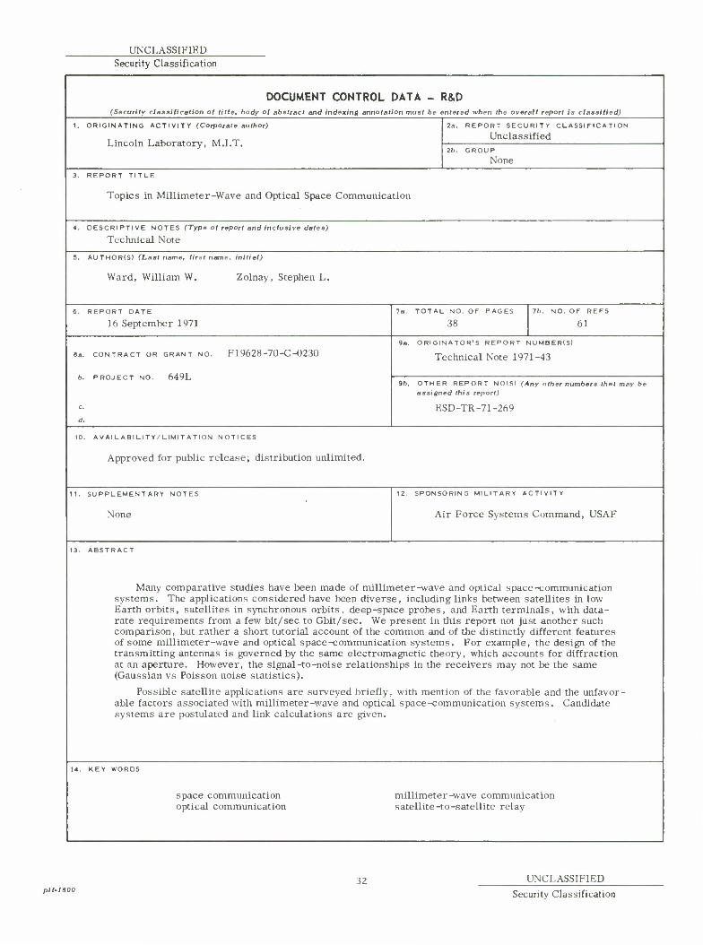
13. ABSTRACT
Many comparative studies have been made of millimeter-wave and optical space-communication systems. The applications considered have been diverse, including links between satellites in low Earth orbits, satellites in synchronous orbits, deep-space probes, and Earth terminals, with data- rate requirements from a few bit/sec to Gbit/sec. We present in this report not just another such comparison, but rather a short tutorial account of the common and of the distinctly different features of some millimeter-wave and optical space-communication systems. For example, the design of the transmitting antennas is governed by the same electromagnetic theory, which accounts for diffraction at an aperture. However, the signal-to-noise relationships in the receivers may not be the same (Gaussian vs Poisson noise statistics).
Possible satellite applications are surveyed briefly, with mention of the favorable and the unfavor- able factors associated with millimeter-wave and optical space-communication systems. Candidate systems are postulated and link calculations are given.
u. KEY WORDS
space communication optical communication
millimeter-wave communication satellite-to-satellite relay
plt-lSOO ^ UNCLASSIFIED
Security Classification