limitorque - envirohk.com · may 2003 limitorque ... mounting base (mss sp-102/iso 5210) fa10/f10...
TRANSCRIPT

Limitorque Actuation Systems130-30000
Rev. EMay 2003
Limitorque®
Accutronix MX Performance and Dimensions
for MX Series 05 through 140 Electric Actuators
Flow Control Division
Limitorque Actuation Systems
Performance and Dimensions: Accutronix MX 130-30000 E2
1
23
4 5
6
78
9
10
11
12
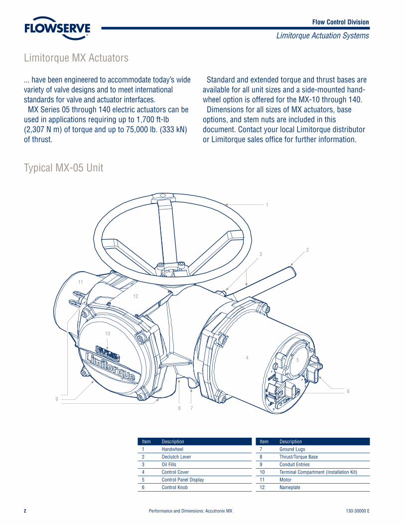
Item Description1 Handwheel2 Declutch Lever3 Oil Fills4 Control Cover5 Control Panel Display6 Control Knob
Item Description7 Ground Lugs8 Thrust/Torque Base9 Conduit Entries10 Terminal Compartment (Installation Kit)11 Motor12 Nameplate
Typical MX-05 Unit
Limitorque MX Actuators
... have been engineered to accommodate today’s widevariety of valve designs and to meet internationalstandards for valve and actuator interfaces.MX Series 05 through 140 electric actuators can be
used in applications requiring up to 1,700 ft-lb(2,307 N m) of torque and up to 75,000 lb. (333 kN)of thrust.
Standard and extended torque and thrust bases areavailable for all unit sizes and a side-mounted hand-wheel option is offered for the MX-10 through 140.Dimensions for all sizes of MX actuators, base
options, and stem nuts are included in thisdocument. Contact your local Limitorque distributoror Limitorque sales office for further information.

Flow Control Division
Limitorque Actuation Systems
130-30000 E Performance and Dimensions: Accutronix MX 3
MX Series Performance Ratings for Units 05 through 140MX-05 through MX-40 (Three-phase–50 Hz/380, 400, and 415 Volt–60 Hz/230, 380, 460, 575 Volt)
MX-85 through MX-140 (Three-phase–50 Hz/3801, 400, and 415 Volt–60 Hz/380, 460, 575 Volt)MX-05 MX-10 MX-20 MX-40 MX-85 MX-140
Output Speed (RPM) Rated Output Torque
60 Hz 50 Hz ft-lb N m ft-lb N m ft-lb N m ft-lb N m ft-lb N m ft-lb N m18 15 55 75 125 170 225 305 440 597 N/A N/A N/A N/A26 22 55 75 125 170 225 305 440 597 850 1153 1500 203640 33 55 75 125 170 225 305 440 597 1225 1662 1700 230752 43 55 75 125 170 225 305 440 597 1150 1561 1600 217177 65 48 65 107 145 178 241 345 468 850 1153 1200 1628100 1312 84 1102 39 53 89 121 148 201 286 388 600 814 815 1106155 1702 127 1432 41 56 89 121 140 190 260 353 450 611 650 882200 165 34 46 73 99 114 155 210 285 N/A N/A N/A N/A
Note 1: 380/50 multiply by 0.9; 380/60 consult factoryNote 2: MX-85 and MX-140
lb. kN lb. kN lb. kN lb. kN lb. kN lb. kNThrust Ratings (lbs/kN) 8000 35 15000 66 25000 111 36000 160 50000 222 75000 333
lb. kg lb. kg lb. kg lb. kg lb. kg lb. kgWeight (lbs/kg) 52 24 65 29 109 49 133 60 250 114 300 136
Maximum Stem CapacityType A Couplings in. mm in. mm in. mm in. mm in. mm in. mmType A1 1.26 32 1.57 40 2.36 60 2.64 67 3.50 88 3.50 88Type A1E (Extended Nut) 1.26 32 1.57 40 2.36 60 2.64 67 3.50 88 3.50 88
Type B Couplings (Torque Only)3
Type B4 1 25.4 1.25 30 1.94 50 2.2 55 2.88 73 2.88 73Type B4E (Extended) 0.75 19 0.91 22 1.56 41 1.78 46 2.25 56 2.25 56Type B1 (Fixed Bore)4 N/A 42 N/A 42 N/A 60 N/A 60 N/A N/A N/A N/A
Type BL (Splined) 6 & 38 Splines 6 & 38 Splines 6 & 36 Splines 6 Splines N/A N/A
Maximum Bore and KeywayMaximum Bore (B4)1 25 1.25 30 1.94 50 2.2 55 2.88 73 2.88 73Key 1/4 sq. 8 x 7 1/4 sq. 10 x 8 1/2 x 3/8 14 x 9 1/2 x 3/8 16 x 10 3/4 x 1/2 20 x 12 3/4 x 1/2 20 x 12Maximum Bore (B4E) .75 18 0.91 22 1.56 41 1.78 46 2.25 56 2.25 56Key 3/16 sq. 6 x 6 1/4 sq. 8 x 7 3/8 sq. 12 x 8 1/2 x 3/8 14 x 9 1/2 x 3/8 16 x 10 1/2 x 3/8 16 x 10
Note 3: Maximum bores for type B couplings may require rectangular keys.Note 4: Available in ISO base only.
MX-05 MX-10 MX-20 MX-40 MX-85 MX-140Mounting Base (MSS SP-102/ISO 5210) FA10/F10 FA10/F10 FA14/F14 FA14/F14 FA16/F16 FA25/F25Handwheel Ratio (STD/Optional) Direct Direct/8:1 Direct/12:1 Direct/24:1 16/48 16/48Side-mounted Handwheel Efficiencies N/A 52% 54% 51% 53%/51%5 53%/51%5
Note 5: Efficiencies for MX-85 and 140 are 51% with SGA and 53% without SGA.
MX Handwheel RimpullOutput Output Output Output
Rated Rimpull Torque (ft-lb) Torque (ft-lb) Torque (ft-lb) Torque (ft-lb)Unit/ Handwheel Gear Torque at Rated at 20 lb. at 40 lb. at 60 lb. at 80 lb.Mounting Diameter (in.) Ratio ft-lb Efficiency Torque (lb.) Rimpull Rimpull Rimpull RimpullMX-05 Top 12 1 55 0.88 125 9 18 26 35MX-05 Top 18 1 55 0.88 83 13 26 40 53MX-10 Top 18 1 125 0.88 189 13 26 40 53MX-10 Side 12 8 125 0.52 60 42 83 125 166MX-20 Top 24 1 225 0.88 256 18 35 53 70MX-20 Side 12 12 225 0.54 69 65 130 194 259MX-40 Top 24 1 440 0.88 500 18 35 53 70MX-40 Side 12 24 440 0.51 72 122 245 367 490MX-85/140 w/o SGA 18 16 600 0.53 88 127 254 382 508MX-85/140 w/SGA 18 48 1574 0.51 86 367 734 1101 1469

Flow Control Division
Limitorque Actuation Systems
Performance and Dimensions: Accutronix MX 130-30000 E4
MX Unit 05 Dimension DataDimensions in inches and millimeters.
19
38
40
4.0(102)
7.5
(190
)
1.4 (37)
4.4
(113
)
2.6(65)
2.3(58)
7.5(190)
4.1
(105
)
9.1(232) Max.
6.5
(166
)
8.7(222)
5.0(127)
13.6(346)
11.4(289) M
ax.7.5(190)
5.5(140)
REMOTE
LOCAL
POTS
(YES)
CLOSE
OPEN
(NO
L i m i t o r q u e
Top View View ADetail of declutch lever
Side View Front View
12
34
O
56 8
7
View B
18 13
18
15 20 17 16
11
9
12
10
21
23
18
22
View BConduit entries with covers removed
13
14
15 16 17
Dimension Key
Drive sleeve
Moto r
Note: Millimeter dimensions are in parentheses.
View A
1.5(38)
DO NOT OPENWHILE ENERGIZED
Limitorque
C
C

Flow Control Division
Limitorque Actuation Systems
130-30000 E Performance and Dimensions: Accutronix MX 5
MX Unit 05 Base DetailsDimensions in inches and millimeters.
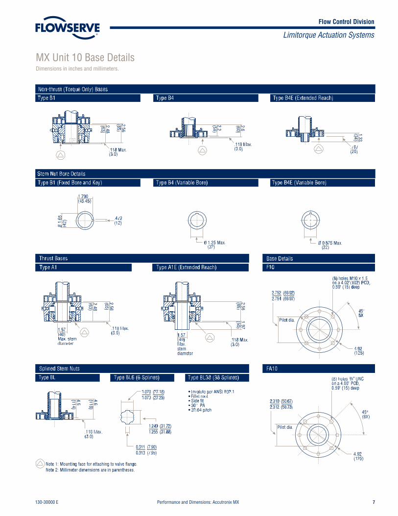
Type B1
Non-thrust (Torque Only) Bases
Type B4 Type B4E (Extended Reach)
Type B1 (Fixed Bore and Key) Type B4 (Variable Bore) Type B4E (Variable Bore)
Stem Nut Bore Details
Note 1: Mounting face for attaching to valve flange.Note 2: Millimeter dimensions are in parentheses.
Type A1 Type A1E (Extended Reach) Base Details
Type BL6 (6 Splines)Type BL
F10
FA10
Type BL38 (38 Splines)
2.2(56)
2.4(60)
.118 Max.(3.0)
2.1(54)
.71(18)
1.1(29)1.8
(46)
(25.4)Max.
(42)
1.790(45.45)
.472(12)
Max.stemdiameter
1.26(32)
1.26(32)
2.1(54)
1.57(40)
2.0(52.5)
2.1(54)
4.5(114)
4.6(118)
4.92(125)
(8) holes M10 x 1.5on a 4.02" (102) PCD,0.59" (15) deep
45°(8X)
4.92(125)
(8) holes 3/ 8" UNCon a 4.00" (102)PCD, 0.59" (15) deep
45°(8X)
.118 Max.(3.0)
.118 Max.(3.0)
.118 Max.(3.0)
Max.stemdiameter
.118 Max.(3.0)
Splined Stem Nuts
Pilot dia.
Pilot dia.
(19)Max.
1.0701.073
(27.18)(27.25)
0.3110.313
(7.90)(7.95)
1.2491.255
(31.72)(31.88)
2.3102.312
(58.67)(58.73)
2.7522.754
(69.92)(69.97)

Flow Control Division
Limitorque Actuation Systems
Performance and Dimensions: Accutronix MX 130-30000 E6
MX Unit 10 Dimension DataDimensions in inches and millimeters.
Flow Control Division
Limitorque Actuation Systems
130-30000 E Performance and Dimensions: Accutronix MX 7
MX Unit 10 Base DetailsDimensions in inches and millimeters.

Flow Control Division
Limitorque Actuation Systems
Performance and Dimensions: Accutronix MX 130-30000 E8
MX Unit 20 Dimension DataDimensions in inches and millimeters.

Flow Control Division
Limitorque Actuation Systems
130-30000 E Performance and Dimensions: Accutronix MX 9
Type B1
Non-thrust (Torque Only) Bases
Type B4 Type B4E (Extended Reach)
Type B1 (Fixed Bore) Type B4 (Variable Bore) Type B4E (Variable Bore)
Stem Nut Bore Details
Note 1: Mounting face for attaching to valve flange.Note 2: Millimeter dimensions are in parentheses.
Thrust Bases
Type A1 Type A1E (Extended Reach)
Base Details
Type BL6 (6 Splines)
F14
FA14
.108(2.75)
.098(2.50)
3.2(81)
2.9(74)
3.1(78) 2.4
(62)
1.8(45)
.098(2.50)
3.3(85)
Ø 1.9375 Max.(49.213)
Ø 1.62 Max.(41.15)
Ø 2.
38(6
0.0) .713
(18.13)
3.2(81)
3.3(85)
.108(2.75)
3.3(85)
2.0(51)
.108(2.75)
2.36(60.0)Max. stemdiameter
2.36(60.0)Max. stemdiameter
4.5(114)
0.098(2.50)
45.0°
Ø 7.0 (175)
4 holes M16-2 x 32 mm deep.Equispaced as shownon a 140.0 mm PCD,1.10" (28) deep
45.0°
Ø 7.0 (175)
4 holes 5/8 -11 UNC.Equispaced as shownon a 5.50" (140) PCD,1.10" (28) deep
Pilot dia.
Pilot dia.
Splined Stem Nuts
Type 36T
• Involute per ANSI B92.1• Fillet root• Side fit• 30° PA• 32/64 pitch
Type BL
4.4(111)
1.2751.278
(32.38)(32.48)
0.3730.377
(9.47)(9.57)
1.5111.517
(38.38)(38.54)
3.9333.935
(99.91)(99.96)
3.7463.748
(95.16)(95.21)
2.5332.545
(64.35)(64.65)
MX Unit 20 Base DetailsDimensions in inches and millimeters.
Flow Control Division
Limitorque Actuation Systems
Performance and Dimensions: Accutronix MX 130-30000 E10
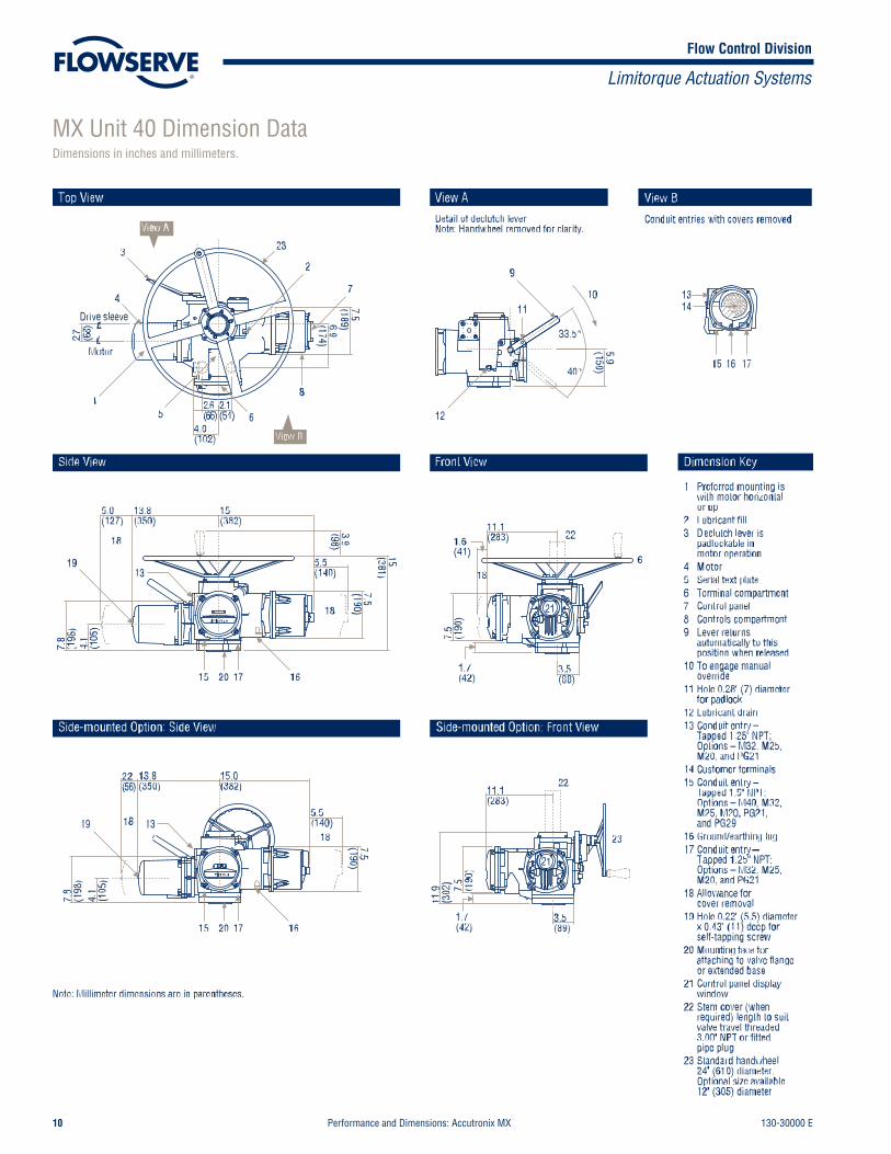
MX Unit 40 Dimension DataDimensions in inches and millimeters.

Flow Control Division
Limitorque Actuation Systems
130-30000 E Performance and Dimensions: Accutronix MX 11
Type B1
Non-Thrust (Torque Only) Bases
Type B4 Type B4E (Extended Reach)
Type B1 (Fixed Bore) Type B4 (Variable Bore)
2.226(55.6)Max.
Type B4E (Variable Bore)
Stem Nut Bore Details
Note 1: Mounting face for attaching to valve flange.Note 2: Millimeter dimensions are in parentheses.
.108 Max.(2.75)
.098 Max.(2.50)
4.5(114)4.4(111)
1.82(46.2)Max.
0.098(2.50)
4 holes M16-2 x 32 mm deep.Equispaced as shownon a 140.0 mm PCD,1.10" (28) deep
45.0°
Ø 7.0 (175)
4 holes 5/8-11 UNC tapx 1.10 deep.Equispaced as shownon a 5.50" (140) PCD,1.10" (28) deep
.098 Max.(2.50)
Ø 2.
38(6
0.0)
3.9(99)
4.0(102)
3.3(85)
3.5(89) 2.8
(70)
2.3(58)
3.9(99)
4.0(101)
.108(2.75)
.108(2.75)
4.0(101)
2.4(61)
2.64(67.0)Max. stemdiameter
2.64(67.0)Max. stemdiameter
Pilot dia.
Thrust Bases
Type A1 Type A1E (Extended Reach)
FA14
45.0°
Ø 7.0 (175)
Pilot dia.
Base Details
F14
Type BL Type BL6 (6 Splines)
Splined Stem Nuts
0.7090.718
(18.03)(18.13)
0.3730.377
(9.47)(9.57)
1.5111.517
(38.38)(38.54)
3.9333.935
(99.91)(99.96)
3.7463.748
(95.16)(95.21)
2.5332.545
(64.35)(64.65)
1.2751.278
(32.38)(32.48)
MX Unit 40 Base DetailsDimensions in inches and millimeters.
Flow Control Division
Limitorque Actuation Systems
Performance and Dimensions: Accutronix MX 130-30000 E12
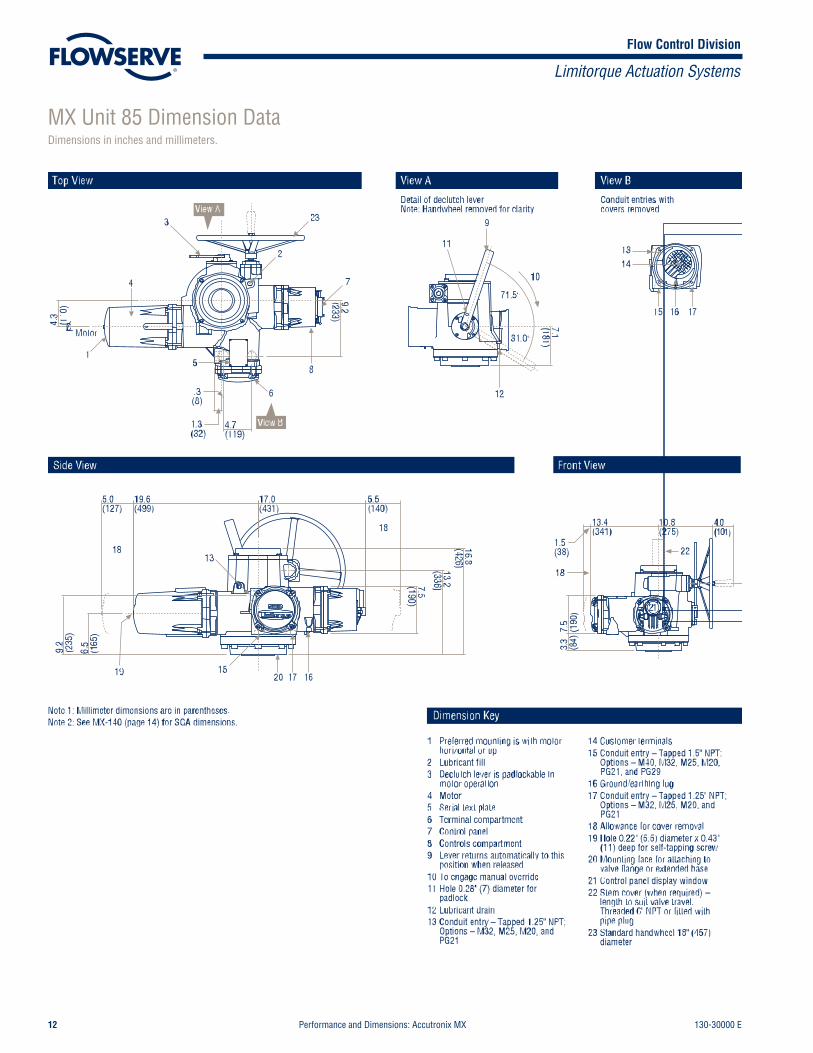
MX Unit 85 Dimension DataDimensions in inches and millimeters.

Flow Control Division
Limitorque Actuation Systems
130-30000 E Performance and Dimensions: Accutronix MX 13
Type A1Thrust Bases
Type A1E (Extended Reach)
Type B4 Type B4E (Extended Reach)Non-thrust (Torque Only) Base
Stem Nut Bore DetailsType B4 (Variable Bore)
FA16F16
Type B4E (Variable Bore)
Base Details
FA25F25
Base Details
Stem Nut Bore Details
Note 1: Mounting face for attaching to valve flange.Note 2: Millimeter dimensions are in parentheses.
5.115.12
(129.82)(130.05)
7.8667.872
(199.80)(199.95)
4.9965.000
(127.00)(129.90)
5.9965.998
(152.30)(152.36)
4 holes 3/4 -10 tap x 1.0 deep.Equispaced as shown on 6.50 (165) B.C. straddle centerline
8 holes 5/8 -11 tap x 1.26 deep.Equispaced as shown on10.00 (254.0) B.C. straddlecenterline
8 holes M16 x 2 x 32 mmdeep. Equispaced as shownon 10.00 (254.0) B.C. straddle centerline
4.9(125)
.18(4.6)
3.50(88.0)Max. bore
4.9(125).18
(4.6)
2.3(60)
4.05(103)Diameter
3.50(88.0)Max. bore
Ø 8.75
45.0°
Ø 8.75
45.0°
4 holes M20 x 2.5 x 25.4 mmdeep. Equispaced as shown on 6.50 (165) B.C. straddlecenterline
Ø 11.8
22.5°
Ø 11.81(300.0)
22.5°
4.6(117)4.4(112)
.20(5.0)
3.11(79)Diameter
4.4(112)
.20(5.0)
3.3(85)
Pilot dia. Pilot dia.
Pilot dia.Pilot dia.
2.25(56)Max.
2.88(73)Max.
MX Unit 85 Base DetailsDimensions in inches and millimeters.

Flow Control Division
Limitorque Actuation Systems
Performance and Dimensions: Accutronix MX 130-30000 E14
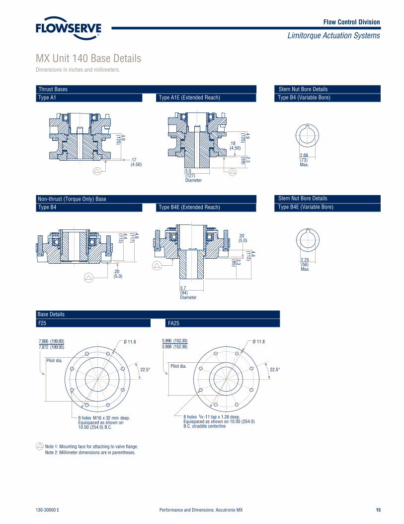
MX Unit 140 Dimension DataDimensions in inches and millimeters.
Flow Control Division
Limitorque Actuation Systems
130-30000 E Performance and Dimensions: Accutronix MX 15
Type A1Thrust Bases
Type A1E (Extended Reach)
Type B4 Type B4E (Extended Reach)Non-thrust (Torque Only) Base
Stem Nut Bore DetailsType B4 (Variable Bore)
F25
Type B4E (Variable Bore)
Base Details
Stem Nut Bore Details
Note 1: Mounting face for attaching to valve flange.Note 2: Millimeter dimensions are in parentheses.
FA25
7.8667.872
(199.80)(199.95)
5.9965.998
(152.30)(152.36)
4.9(125)
.17(4.50)
Ø 11.8
22.5°
5.0(127)Diameter
2.3(59)
.18(4.50)
4.9(125)
3.7(94)Diameter
.20(5.0)
3.3(85)
4.4(112)
.20(5.0)
4.4(112)
4.6(117)
Ø 11.8
22.5°
Pilot dia.Pilot dia.
8 holes 5/8 -11 tap x 1.26 deep.Equispaced as shown on 10.00 (254.0)B.C. straddle centerline
2.88(73)Max.
2.25(56)Max.
8 holes M16 x 32 mm deep.Equispaced as shown on10.00 (254.0) B.C.
MX Unit 140 Base DetailsDimensions in inches and millimeters.

Limitorque5114 Woodall Road, P.O. Box 11318Lynchburg, VA 24506-1318Phone (434) 528-4400, Fax (434) 845-9736http://www.limitorque.com
LimitorqueAbex RoadNewburyBerkshire, RG14 5EYEngland Phone 44-1-635-46999Fax 44-1-635-36034
Limitorque Nippon Gear Co., Ltd.Asahi-Seimei Bldg. 4th Floor1-11-11 Kita-Saiwai, Nishi-KuYokohama-Shi, (220-0004)JapanPhone 81-45-326-2065Fax 81-45-320-5962
Limitorque India, Ltd.302, Mansarovar 90 Nehru PlaceNew Delhi - 110019IndiaPhone 91-11-6431-748Fax 91-11-6432-749
Flowserve Australia Pty., Ltd. 14 Dalemore DriveScoresby, Victoria 3179 Australia Phone 613-9729-2633Fax 613-9729-2644
Limitorque Asia, Pte., Ltd.12, Tuas Avenue 20Singapore 638824Phone 65-6868-4628Fax 65-6862-4940
© 2003 Flowserve Corporation, Irving, Texas, USA. Flowserve and Limitorque are registered trademarks of Flowserve Corporation. 130-30000 Rev. E 5/03 Printed in USA
Flow Control Division
Limitorque Actuation Systems
Flowserve Corporation has established industry leadership in the design and manufacture of its products. When properly selected, this Flowserve product is designed to perform its intended function safely during its useful life. However, the purchaser or user of Flowserve products should be aware that Flowserve products might be used innumerous applications under a wide variety of industrial service conditions. Although Flowserve can (and often does) provide general guidelines, it cannot provide specificdata and warnings for all possible applications. The purchaser/user must therefore assume the ultimate responsibility for the proper sizing and selection, installation, operation, and maintenance of Flowserve products. The purchaser/user should read and understand the Installation and Maintenance (I & M) instructions included with theproduct, and train its employees and contractors in the safe use of Flowserve products in connection with the specific application.
While the information and specifications contained in this literature are believed to be accurate, they are supplied for informative purposes only and should not be considered certified or as a guarantee of satisfactory results by reliance thereon. Nothing contained herein is to be construed as a warranty or guarantee, express or implied,regarding any matter with respect to this product. Because Flowserve is continually improving and upgrading its product design, the specifications, dimensions and information contained herein are subject to change without notice. Should any question arise concerning these provisions, the purchaser/user should contact FlowserveCorporation at any one of its worldwide operations or offices.
FLOWSERVE CORPORATIONFLOW CONTROL DIVISIONLimitorque Actuation Systems5114 Woodall RoadP.O. Box 11318Lynchburg, VA 24506-1318Phone: 434 528 4400Facsimile: 434 845 9736www.limitorque.com
For more information about Flowserve Corporation, contact www.flowserve.com or call USA 1-800-225-6989