limitorque mx/qx actuators -...
TRANSCRIPT

Experience In Motion
TECHNICAL BULLETIN
Limitorque MX/QX ActuatorsProtection, Control and Monitoring Features
FCD LMENTB2300-04 – 11/13

MX/QX Protection, Control and Monitoring Features FCD LMENTB2300-04 – 11/13
2
Table of Contents Section Page1. Standard Control Features 6
1.1 Basic Specifications 61.2 Local Control 61.3 Local Indication 61.4 Remote Control Modes of Operation 71.5 Remote Control Type 71.6 Remote Control Signal Power 71.7 External Power Supply 71.8 Standard Internal Power Supply 71.9 Emergency Shutdown (ESD) 81.10 Remote External Interlocks/Inhibits 81.11 MX Absolute Position Encoder 81.12 QX Absolute Position Encoder 9
2. Protection Features 92.1 LimiGard™ Circuit Protection 102.2 Autophase Protection and Correction 102.3 Jammed Valve Protection 102.4 Instantaneous Reversal Protection 102.5 Motor Thermal Protection 10
3. Optional Control Features 113.1 Modutronic 113.2 Analog Position Transmitter (APT) 113.3 Analog Torque Transmitter (ATT) 123.4 Two-Speed Timer 123.5 QX Speed Control 123.6 Control Station (CSE) 123.7 Isolation and Load Break Switches 123.8 Lost Power Buffer — MX/QX Quik™ 133.9 Custom Software Mode #1 — Momentary Contact ESD and Partial Stroke ESD 133.10 Custom Software Mode #2 133.11 Custom Software Mode #3 133.12 Custom Software Mode #4 14
4. Network Communications 144.1 DDC (Distributed Digital Control) Communication — Modbus™ 144.2 Master Station III 144.3 Foundation Fieldbus Communication 154.4 Profibus DP V1 Communication 154.5 Profibus PA Communication 154.6 Device Type Manager (DTM) for Profibus DP/PA & Foundation Fieldbus 164.7 DeviceNet Communication 164.8 HART Communication 16
5. Monitoring and Diagnostic Facilities 175.1 Local Facilities 175.2 Diagnostics 18
3
MX/QX Protection, Control and Monitoring Features FCD LMENTB2300-04 – 11/13
flowserve.com
Section Page6. Remote Facilities 19
6.1 Actuator Status Contacts (S1a, S1b, S2a, S2b) 196.2 Monitor Relay (SM) 206.3 Optional Alarm Status Contacts (R1, R2, R3, R4, R5, R6, R7, R8) 206.4 Exact End Position Indication 20
7. Auxiliary Power Supply — Uninterruptible Power Supply (UPS) Connection 218. Isolated Commons 219. Bluetooth® Wireless Communications and MX/QX Dashboard™ Software 2110. Actuator Configuration 23
10.1 Non-Intrusive Local Configuration 2310.2 Default Configuration 23
11. MX and QX Specifications 2511.1 Global Certifications 2511.2 Wiring 2511.3 Valve Interface 2511.4 Design Life and Endurance 2511.5 Diagnostic Features 2611.6 Factory Test 2611.7 Conduit Entries 2611.8 European Directives 26
12. Wiring Configurations for the MX and QX 2812.1 MX/QX Terminal Block 2812.2 Wiring Diagram Configurator 28
13. MX and QX Wiring Diagrams 2914. Network Protocol Connections 34
14.1 Network Wiring — DDC-Modbus 3414.2 Network Wiring — Foundation Fieldbus H1 3614.3 Network Wiring — Profibus DP and PA 3814.4 Network Wiring — DeviceNet 4114.5 Network Wiring — HART 42
MX/QX Protection, Control and Monitoring Features FCD LMENTB2300-04 – 11/13
4
Figures and Tables Section PageFigure 1.1 – MX/QX Control Panel 6Figure 1.2 – MX Absolute Position Encoder 8Figure 1.3 – QX Absolute Position Encoder 9Table 3.1 – Speed Control 12Figure 9.1 – Normal and Diagnostic Displays 22Figure 10.1 – Default Configuration Guidelines 24Figure 10.2 – Configuring the MX or QX Actuator 24Table 11.1 – EMC Test Criteria 27Figure 12.1 – MX/QX Terminal Block 28Figure 13.1 – Standard Wiring Diagram for MX/QX Actuators 29Figure 13.2 – Optional Features Wiring Diagrams 30Figure 13.3 – DDC, Foundation Fieldbus, Profibus DP_V1, Redundant Profibus DP_V1,
Profibus PA, and DeviceNet Network Wiring Diagrams 31Figure 13.4 – DDC, Foundation Fieldbus and Profibus Optional Features Wiring Diagrams 32Figure 13.5 – Remote Wiring Connections 33Figure 14.1 – Typical Modbus Network Wiring Diagrams — Redundant Bi-Directional Loop 35Figure 14.2 – HART Wiring Connection 36Figure 14.3 – Typical Foundation Fieldbus Network With DCS or PLC as the Host System 37Table 14.1 – Specifications for the Profibus DP Cable 38Table 14.2 – Specifications for the Profibus PA Cable 38Figure 14.4 – Profibus Distance vs. Baud Rate Chart 38Figure 14.5 – Typical Profibus DP Network (Daisy Chain Shown) 39 Figure 14.5a – Typical Profibus DP Network With Redundancy Option (Single Master) 39 Figure 14.5b – Typical Profibus DP Network With Redundancy Option (Dual Master) 39 Figure 14.5c – Typical Profibus PA Network 40Table 14.3 – Belden Cable Specifications 41Table 14.4 – Total Cable Length Between Repeaters or Nodes 41Figure 14.6 – Typical DeviceNet Network 41Figure 14.7 – Typical HART System With a DCS Host 42

5
MX/QX Protection, Control and Monitoring Features FCD LMENTB2300-04 – 11/13
flowserve.com
IntroductionThis document details the protection, control and monitoring capabilities of the MX and QX ranges of electronic actuators.
The Flowserve Limitorque MX/QX non-intrusive actuator consists of a mechanical gearbox powered by an electric motor (a brushless DCV design for the QX). The MX is controlled by an integral electro-mechanical starter, the QX by a solid state motor controller, and both employ state-of-the-art SMT (surface mount technology) controls. Each MX/QX is double-sealed and weatherproof to IP68 (15 m for 96 hours for the MX and 20 m for 168 hours for the QX), NEMA 4, 4X, and 6, with hazardous location versions available.
For detailed menu configurations, please refer to bulletin LMENIM2306 for MX and LMENIM3306 for QX.
Standard Application Voltages with +/- 10% Nominal Range Design Voltage Application Voltage
24 VDC* 24-48 VDC*
115 VAC, 60 Hz, 1 ph* 110/115/120 VAC, 60 Hz, 1 ph*
230 VAC, 60 Hz, 1 ph* 230 VAC, 60 Hz, 1 ph*
230 VAC, 50 Hz, 1 ph*
230 VAC, 60 Hz, 3 ph 208/220/230/240 VAC, 60 Hz, 3 ph
460 VAC, 60 Hz, 3 ph 380/400/415/440 VAC, 50 Hz, 3 ph
380/440/460/480 VAC, 60 Hz, 3 ph
525 VAC, 50 Hz, 3 ph 525 VAC, 50 Hz, 3 ph
575 VAC, 60 Hz, 3 ph 550/575/600 VAC, 60 Hz, 3 phPlease contact Flowserve Limitorque for other voltage requirements.
*Future Implementation for the MX. Available for the QX. Consult factory.
MX/QX Protection, Control and Monitoring Features FCD LMENTB2300-04 – 11/13
6
1. Standard Control Features1.1 Basic SpecificationsThe MX and QX wiring diagrams are very similar and can be accessed at www.flowserve-wiring.com. This site permits a user to configure either an MX or QX to their specifications. The standard wiring diagram is shown in Figure 11.1. Optional wiring diagrams are on subsequent pages. The most current wiring diagram is located within the terminal compartment.
The following control features are included in the basic specification.
For Optional Features, please refer to Section 2.3 Optional Control Features.
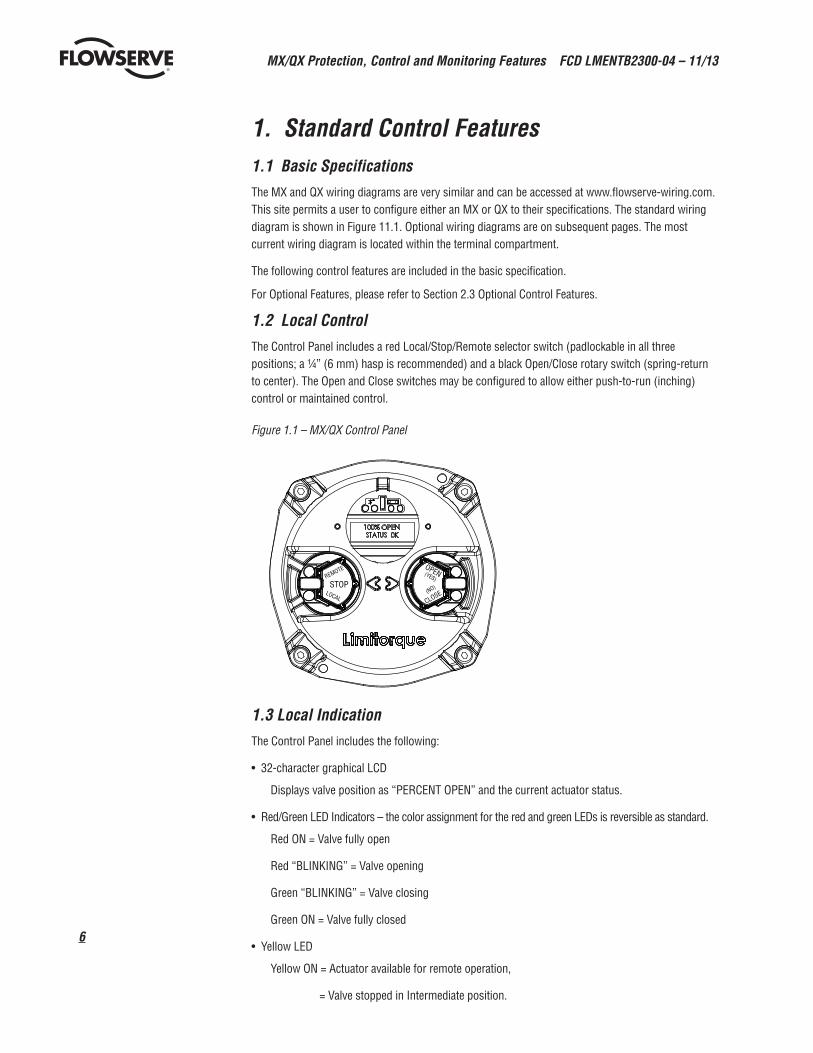
1.2 Local ControlThe Control Panel includes a red Local/Stop/Remote selector switch (padlockable in all three positions; a ¼” (6 mm) hasp is recommended) and a black Open/Close rotary switch (spring-return to center). The Open and Close switches may be configured to allow either push-to-run (inching) control or maintained control.
Figure 1.1 – MX/QX Control Panel
D
C
B
A
B
C
D
12345678
8 7 6 5 4 3 2 1
E
F
E
F
AF-2564 Cover assy SHEET 1 OF 1
UNLESS OTHERWISE SPECIFIED:
SCALE: 1:2 WEIGHT:
REVDWG. NO.
CSIZE
TITLE:
NAME DATE
COMMENTS:
Q.A.
MFG APPR.
ENG APPR.
CHECKED
DRAWN
FINISH
MATERIAL
INTERPRET GEOMETRICTOLERANCING PER:
DIMENSIONS ARE IN INCHESTOLERANCES:FRACTIONAL±ANGULAR: MACH± BEND ±TWO PLACE DECIMAL ±THREE PLACE DECIMAL ±
APPLICATION
USED ONNEXT ASSY
PROPRIETARY AND CONFIDENTIAL
THE INFORMATION CONTAINED IN THISDRAWING IS THE SOLE PROPERTY OF<INSERT COMPANY NAME HERE>. ANY REPRODUCTION IN PART OR AS A WHOLEWITHOUT THE WRITTEN PERMISSION OF<INSERT COMPANY NAME HERE> IS PROHIBITED.
A
DO NOT SCALE DRAWING
CLOSESTOP
OPEN(YES)REMOTE
LOCAL(NO)
1.3 Local IndicationThe Control Panel includes the following:
• 32-character graphical LCD
Displays valve position as “PERCENT OPEN” and the current actuator status.
• Red/Green LED Indicators – the color assignment for the red and green LEDs is reversible as standard.
Red ON = Valve fully open
Red “BLINKING” = Valve opening
Green “BLINKING” = Valve closing
Green ON = Valve fully closed
• Yellow LED
Yellow ON = Actuator available for remote operation,
= Valve stopped in Intermediate position.
7
MX/QX Protection, Control and Monitoring Features FCD LMENTB2300-04 – 11/13
flowserve.com
Yellow “BLINKING” = Monitor Relay de-energized, actuator not available for remote operation.
• Blue LED
Bluetooth option enabled and link established
1.4 Remote Control Modes of OperationThe actuator may be controlled remotely by two, three or four wires.
•Four-Wire Control – Three maintained contacts for “push-and-release” control. Valve can be opened, closed or stopped.
•Two-Wire Control – One (open or closed) maintained contact for “push-and-release” control. Valve can be opened or closed, but not stopped in mid-travel.
•Three-Wire Maintained – Two maintained contacts for “push-and-release” control. Valve can be opened or closed but not stopped in mid-travel.
•Three-Wire Inching – Two momentary contacts for “push-to-run” control. Valve can be opened, closed and stopped in mid-travel.
Refer to Figure 12.6 for remote wiring connections.
1.5 Remote Control TypeThe actuator may be placed in digital only, modulation only, network only, or multi-command types.
•Digital (Discrete) Only Control Type – Only digital input commands are recognized and acted upon. All other types of remote control commands are ignored.
•Analog (Modutronic) Only Control Type – Only Modutronic 4-20 mA commands are recognized and acted upon. All other types of remote control commands are ignored.
•Network Only Control Type – Only network (DDC, Fieldbus, Profibus, Device Net) commands are recognized and acted upon. All other types of remote control commands are ignored.
•Multi-control Mode Operation – there are three modes of remote control when remote mode is configured for multi control: digital control, analog control, and network control. Digital and network control operation is based on the last command received. Analog operation is initiated by either toggling user input 2 (configure for CSE input) or breaking & reapplying the analog control.
1.6 Remote Control Signal PowerPower for remote control signals may be derived internally from the actuator or provided externally by the user. Signals can range from 24 to 125 VAC or VDC.
1.7 External Power Supply An external power supply in the range of 12 to 24 VDC may be provided by the user. 1.8 Standard Internal Power SupplyThe standard internal signal supply is 24 VDC. The 24 VDC supply offers a maximum loading of 5 W. The 24 VDC supply, in conjunction with the opto-isolated digital inputs, allows control from remote volt-free contacts over long distances and simplifies the user’s control scheme. An optional 120 VAC, 15 VA internal power supply is available (consult factory). Standard control employs a negative earth. Positive earth (negative switching) is available by wiring to the (+) positive common as shown on the wiring diagrams.
MX/QX Protection, Control and Monitoring Features FCD LMENTB2300-04 – 11/13
8
1.9 Emergency Shutdown (ESD)
Up to three independent ESD signals may be applied, prioritized and configured for different actions for the ESD event associated with each. Either of these ESD signals may be applied to the actuator to override any existing command signal and send the valve to its preselected shutdown position, providing the actuator is in Remote mode (default configuration for ESD is “Ignore, take no action”). Any new command signal will be ignored until the ESD signal is removed. During setup, the actuator may be configured to close, open, stop, take no action, or “move to a previously configured position” on receipt of the ESD signal. The ESD action may also be configured to override any inhibit signal, the local selector switch, the local stop switch, an overtorque condition, lost phase, or jammed valve protection. Motor thermal protection may be bypassed for critical ESD applications in non-hazardous or special service locations. Disabling the motor thermostat voids all third-party certifications, including Factory Mutual, CSA, IECEx, and ATEX.
1.10 Remote External Interlocks/InhibitsThree user-defined inputs are provided for the connection of remote contacts that will prevent motor-ized operation of the actuator. These are effective in both Remote and Local modes and may only be overridden by a maintained ESD signal, if so configured (refer to Figure 12.5 for wiring connections). For ESD connections, the user may select either a single common or isolated commons.
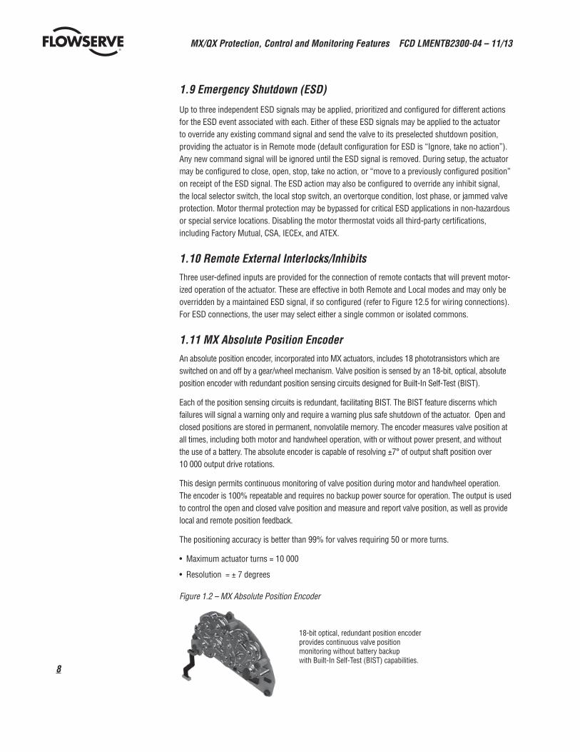
1.11 MX Absolute Position EncoderAn absolute position encoder, incorporated into MX actuators, includes 18 phototransistors which are switched on and off by a gear/wheel mechanism. Valve position is sensed by an 18-bit, optical, absolute position encoder with redundant position sensing circuits designed for Built-In Self-Test (BIST).
Each of the position sensing circuits is redundant, facilitating BIST. The BIST feature discerns which failures will signal a warning only and require a warning plus safe shutdown of the actuator. Open and closed positions are stored in permanent, nonvolatile memory. The encoder measures valve position at all times, including both motor and handwheel operation, with or without power present, and without the use of a battery. The absolute encoder is capable of resolving ±7° of output shaft position over 10 000 output drive rotations.
This design permits continuous monitoring of valve position during motor and handwheel operation. The encoder is 100% repeatable and requires no backup power source for operation. The output is used to control the open and closed valve position and measure and report valve position, as well as provide local and remote position feedback.
The positioning accuracy is better than 99% for valves requiring 50 or more turns.
• Maximum actuator turns = 10 000
• Resolution = ± 7 degrees
Figure 1.2 – MX Absolute Position Encoder
18-bit optical, redundant position encoder provides continuous valve position monitoring without battery backup with Built-In Self-Test (BIST) capabilities.
9
MX/QX Protection, Control and Monitoring Features FCD LMENTB2300-04 – 11/13
flowserve.com
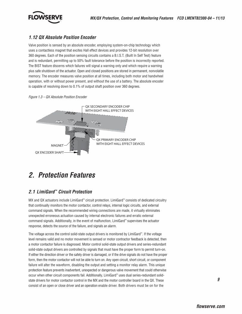
1.12 QX Absolute Position EncoderValve position is sensed by an absolute encoder, employing system-on-chip technology which uses a contactless magnet that excites Hall effect devices and provides 12-bit resolution over 360 degrees. Each of the position sensing circuits contains a B.I.S.T. (Built In Self Test) feature and is redundant, permitting up to 50% fault tolerance before the position is incorrectly reported. The BIST feature discerns which failures will signal a warning only and which require a warning plus safe shutdown of the actuator. Open and closed positions are stored in permanent, nonvolatile memory. The encoder measures valve position at all times, including both motor and handwheel operation, with or without power present, and without the use of a battery. The absolute encoder is capable of resolving down to 0.1% of output shaft position over 360 degrees.
Figure 1.3 – QX Absolute Position Encoder
QX SECONDARY ENCODER CHIP WITH EIGHT HALL EFFECT DEVICES
QX PRIMARY ENCODER CHIP WITH EIGHT HALL EFFECT DEVICESMAGNET
QX ENCODER SHAFT
2. Protection Features 2.1 LimiGard™ Circuit Protection
MX and QX actuators include LimiGard™ circuit protection. LimiGard™ consists of dedicated circuitry that continually monitors the motor contactor, control relays, internal logic circuits, and external command signals. When the recommended wiring connections are made, it virtually eliminates unexpected erroneous actuation caused by internal electronic failures and erratic external command signals. Additionally, in the event of malfunction, LimiGard™ supervises the actuator response, detects the source of the failure, and signals an alarm.
The voltage across the control solid-state output drivers is monitored by LimiGard™. If the voltage level remains valid and no motor movement is sensed or motor contractor feedback is detected, then a motor contactor failure is diagnosed. Motor control solid-state output drivers and series-redundant solid-state output drivers are controlled by signals that must have the proper form to permit turn-on. If either the direction driver or the safety driver is damaged, or if the drive signals do not have the proper form, then the motor contactor will not be able to turn on. Any open circuit, short circuit, or component failure will alter the waveform, disabling the output and setting a monitor relay alarm. This unique protection feature prevents inadvertent, unexpected or dangerous valve movement that could otherwise occur when other circuit components fail. Additionally, LimiGard™ uses dual series-redundant solid-state drivers for motor contactor control in the MX and the motor controller board in the QX. These consist of an open or close driver and an operation enable driver. Both drivers must be on for the
MX/QX Protection, Control and Monitoring Features FCD LMENTB2300-04 – 11/13
10
motor to run, but only one needs to be off to stop the valve. The use of two drivers prevents an inability to stop the actuator due to a relay failure. All LimiGard™ alarms are signalled by de-energizing the monitor relay and communicated via the diagnostic screens. Valve operation is inhibited until the failure is corrected; referred to as “Fail No Action.”
LimiGard™ requires that external control signals (Open-Stop-Close-ESD-Inhibit) have a minimum pulse width of 250–350 ms to be considered valid. This minimum pulse width ensures that brief, noisy signals will not cause the valve to move. The signal must have a level of 17–22 V to turn on the input, and the input will not turn off until the level drops below 5–10 VDC. This “signal hysteresis” (> 8 VDC) prevents weak and erratic signals from stopping or initiating valve operation. Additionally, LimiGard™ incorporates optical couplers to protect the input circuits from high voltage transients on the remote control signals.
The LimiGard™ feature may also be extended to external wiring (customer supplied). One method of securing the external wiring is shown in Figure 12.5. Proper function depends upon setting Remote Input mode to “LimiGard,” which configures redundant inputs for the OPEN, CLOSE, and STOP inputs. Both OPEN or CLOSE signals must be present to allow motor motion, while loss of either STOP signal will stop the actuator and prevent further operation in REMOTE mode. The customer is responsible for external wiring system safety. LimiGard has been enhanced with the addition of the 18-bit encoder with BIST for the MX and Hall effect sensor (system on a chip) absolute QX encoder, both with redundant sensing circuits.
2.2 Autophase Protection and CorrectionThe phase rotation of the incoming three-phase supply is continuously monitored. In the event that field wiring is reversed, MX or three phase QX controls automatically correct to ensure the valve operates in the commanded direction. In addition, the detector circuit monitors the presence of all three phases. If a phase is lost, valve starting will be prevented and the user alerted via an LCD error message and Monitor Relay Alarm.
2.3 Jammed Valve ProtectionIf the actuator cannot overcome the required valve starting torque, a jammed valve condition occurs. Jammed valve protection senses the lack of valve movement and initiates a brief reverse/forward cycle to free the valve. If this is unsuccessful, further electrical operation is prevented and the monitor relay is signaled.
2.4 Instantaneous Reversal ProtectionThe control logic incorporates a brief time delay (from 0.5 to 1.0 second) between motor reversals. This reduces motor current surges and prolongs the life of the contactor. Note: It is not necessary to switch to STOP before reversing the actuator.
2.5 Motor Thermal ProtectionThe MX/QX motor is protected against overheating by a thermistor embedded in the motor windings. Standard thermistor threshold is set for 120˚C (Class B). Options are available for other classifica-tions. The QX motor is unique to quarter-turn electronic valve actuators. It is a brushless DC motor specifically designed for the QX operator and complies with IEC 34, S2-50% duty cycle at 50% of rated torque. The motors are true bolt-on designs with a quick disconnect plug which can be changed rapidly without sacrificing motor leads. It is equipped with a solid state motor thermistor to prevent damage due to temperature overloads.
11
MX/QX Protection, Control and Monitoring Features FCD LMENTB2300-04 – 11/13
flowserve.com
3. Optional Control Features 3.1 ModutronicThe Modutronic controller will alter valve position in proportion to an analog command signal. It includes an automatic pulsing mode to reduce overshoot at the set point.
The following parameters may be easily set during the configuration of the unit:
• Proportional Band range from 0.1% to 100% (15% = default)
• Dead Band range from ± 0.1% from nominal deadband setting 50% (2% = default)
• Polarity 20 mA = OPEN (default) or 20 mA = CLOSE
• Action on loss of command signal OPEN, CLOSE, STOP (CLOSE = default), or Move-to a previously configured position
• Delay after stop 0–60 seconds (0 = default)
• Command Signal
• 4–20 mA
• Input impedance: 150 ohms
Repeatability – In the MXa, the Modutronic is repeatable to within ±0.5%. For the QX and QXM, Modutronic is repeatable to +/- 0.1% of nominal deadband setting. Repeatability is defined as encoder feedback position versus position command. Overall valve and actuator system accuracy depends on many factors, including actuator gearing backlash and valve/actuator coupling tolerance, and therefore cannot be defined by this document.
Extrema Mode – If the command signal represents a position of 0–2% OPEN (nominal 4.00–4.32 mA) or 98–100% OPEN (nominal 19.68–20.00 mA), then the MX/QX will move the valve directly to that position, without pulsing.
Positioning Frequency – The standard frequency is suitable for a rate of 600 starts/hour for short periods, typical of process start-up. Typical process control is considered to be ≤ 100 starts/hour. An optional solid-state motor reverser (SSMR) is available for the MX for process rates > 600–1200 starts/hour. The QX uses solid state technology as standard and is rated at up to ≤ 600 starts per hour. From 600–1800 starts per hour, per IEC 34, S4_50%_1800 S/H. This application is also optional for the QX/QXM.
Note: For modulating control on valves of less than 30 second Open to Close operation, please consult factory.
3.2 Analog Position Transmitter (APT)The APT is an internally powered, non-contacting valve position transmitter. The isolated output signal is proportional to the position of the valve and is available as 4–20 mA and/or 0 – 20 mA, 0– 10 VDC, 2–10 VDC, 0 – 5 VDC, or 1– 5 VDC.
The user may select the minimum signal to represent either the fully OPEN or the fully CLOSE position of the valve during the setup procedure.
The transmitted analog signal will correspond to the following parameters:
• Accuracy = 99% of full scale value (for Drive Sleeve Turns > 50)
• Non-Linearity = ± 1% of full scale value
• Impedance = 0–600 ohms (4–20 mA signal)
• Minimum external load = 1000 ohms (0–10 VDC signal)
MX/QX Protection, Control and Monitoring Features FCD LMENTB2300-04 – 11/13
12
3.3 Analog Torque Transmitter (ATT)The ATT is internally powered and provides an electrically isolated output signal of 4–20 mA and/or 0-20 mA, 0 –10 VDC, 2 –10 VDC, 0– 5 VDC, or 1– 5 VDC, which is proportional to actuator rated output torque.
The transmitted analog signal will correspond to the following parameters:
• Accuracy = 99% of full scale value
• Non-Linearity = ± 1% of full scale value
• Impedance= 0–600 ohms (4–20 mA signal)
• Minimum external load = 1000 ohms (0–10 VDC signal)
3.4 Two-Speed Timer A two-speed pulsing timer can be enabled to extend the operating time in the close and/or the open directions. Pulsing may be applied from 0.5 (if precision is set to xxx.x%) to 99% of full valve travel or to a small portion. The ON pulsing cycle is configurable from 0.5 to 20 seconds in 0.5 second increments, and the OFF pulsing cycle is configurable from 1.0 to 200 seconds in 1 second incre-ments. The two-speed timer is especially effective where concerns of hydraulic shock exist.
3.5 QX Speed ControlThe QX permits operational speeds in either Open and Closed directions to be set independently of each other. The QX also has an industry leading span for the optional two-speed timer.
Table 3.1 – Speed ControlSpeed Minimum (Open to Close)
Speed Maximum (Open to Close)
Two speed timer span “On” pulse
Two speed timer span “Off” pulse
QX-1 = 5 seconds QX-1 = 20 seconds 0.5 to 20 seconds (0.5 sec. increments)
1.0 to 200 seconds (1.0 sec. increments)
QX-2 = 5 seconds QX-2 = 30 seconds 0.5 to 20 seconds (0.5 sec. increments)
1.0 to 200 seconds (1.0 sec. increments)
QX-3 = 15 seconds QX-3 = 60 seconds 0.5 to 20 seconds (0.5 sec. increments)
1.0 to 200 seconds (1.0 sec. increments)
QX-4 = 30 seconds QX-4 = 120 seconds 0.5 to 20 seconds (0.5 sec. increments)
1.0 to 200 seconds (1.0 sec. increments)
QX-5 = 60 seconds QX-5 = 120 seconds 0.5 to 20 seconds (0.5 sec. increments)
1.0 to 200 seconds (1.0 sec. increments)
3.6 Control Station (CSE)The CSE is a separate control station designed for the operation of inaccessible actuators. It is available with LEDs, Remote/Local and Open/Close selector switches. The CSE may be powered by the actuator internal supply, provided wire resistance and other external loads do not limit the available signal power presented to the MX.
3.7 Isolation and Load Break SwitchesIsolation and Load Break Switches can be supplied for the incoming three-phase supply to the actuator. These may be coupled directly to the actuator for weatherproof (WP) applications only or supplied separately for mounting by user. The enclosure is suitable for weatherproof or temporary submersion service. An explosion-proof (XP) isolation switch is also available for user mounting. It is suitable for mounting with all MX/QX actuators. Please contact factory for availability.
13
MX/QX Protection, Control and Monitoring Features FCD LMENTB2300-04 – 11/13
flowserve.com
3.8 Lost Power Buffer — MX/QX Quik™
After the actuator has been powered by line power for one hour, it can automatically withstand most power outages while maintaining the correct state of the S or R status contacts, even if the user reposi-tions the actuator manually with the handwheel. To maximize its self-power time while the line power is lost, the actuator places itself in its lowest possible power usage mode. The LCD will darken (sleep mode) until it is needed to be viewed. The LCD can be activated by moving the black knob to OPEN (YES) or by moving the actuator with the handwheel. After the programmable period of inactivity, the LCD returns to sleep mode. When a full charge is available the actuator’s status can be acquired locally for up to 3 hours minimum. The maximum amount of Quik time available varies and depends upon the number of option boards within the MX or QX. The use of batteries to perform this function is not required.
3.9 Custom Software Mode #1 — Momentary Contact ESD and Partial Stroke ESDAn optional, custom software has been developed which, when combined with the unique safety features of the MX or QX actuator, permits a unique scope of performance for Partial stroke and Emergency Shutdown installations.
When enabled, a User may set up the partial stroke and ESD signals as redundant digital inputs for safety. There are two signal inputs for either selection, and both must be in the active state in order for the specific function to occur.
If the partial stroke enable inputs are not active, in a fault state, or are released by the control logic and a signal is detected on the momentary ESD/PSESD input, then the actuator will perform the configured ESD operation. The momentary ESD/PSESD input will be ignored if there is a signal present for less than 100 msec, and is guaranteed to latch in the ESD/PSESD if the signal is present for greater than 800 ms. ESD is active until the control logic ESD Release is given.
3.10 Custom Software Mode #2Custom software is available for the MX that permits the user to establish certain performance characteristics, momentary contact closure ESD and 4-wire remote control.
The ESD release signals are set up as redundant signals for safety. There are two signal inputs, and BOTH must be in the active state. If there is an active ESD and both ESD release inputs are in the active state, the ESD will be unlatched and the unit will return to normal operation. If the ESD release inputs are in a fault state, an active ESD will NOT be released. The ESD release inputs will have no effect on a partial stroke ESD test. The momentary ESD input will be ignored if there is a present for less than 100 ms, and is guaranteed to latch in the ESD if the signal is present for greater than 800 ms. Once the ESD is latched in, the unit will perform the ESD action. In this case the ESD will move the unit to the close limit and remain in ESD mode until the ESD release indication is given using the ESD release inputs.”
3.11 Custom Software Mode #3The ESD Time Delay Relay input (input 0) functions like any normal ESD input signal. Only if a time has been entered into the Delay Timer value then the unit will not act on that ESD for that delayed amount of time. If the ESD signal is removed, then the timer is canceled and will start fresh with the next assertion. You cannot change that Input 0 is ESD, but it can be enabled/disabled, set to signal present/absent, or you can change the ESD action.
MX/QX Protection, Control and Monitoring Features FCD LMENTB2300-04 – 11/13
14
3.12 Custom Software Mode #4The custom input Multi Position Mode allows the user to configure up to two mid-travel stop positions. The user will be able to send the actuator to either of these positions in either remote or local controls. In order to use local controls in multi-mode, that option will need to be selected in the CHANGE LOCAL Control menu. The user can select any of the standard wire controls for inputs 3, 4, and 5 (4-wire, 3-wire Maintain, or 3-wire Inching).
Please contact factory for application and purchase.
4. Network CommunicationsThe MX/QX provides a comprehensive network option portfolio to the user. Network solutions are improved with the addition of DeviceNet to complement Modbus, Foundation Fieldbus H1, Profibus DP_V1 PROFIBUS PA and HART Communications. Both smart actuators provide the user with predictable, reliable, and safe operation for years to come, in applications which are subject to the most rigorous requirements and environmental extremes.
With each of the provided network protocols a user may configure the unit to move to a predefined fail-safe position on loss of communication. Action on loss of command signal OPEN, CLOSE, STOP, or MOVE-TO preconfigured position. The user may also configure the length of time communication must be lost before the unit indicates communication loss and performs the communication loss action.
Please see Section 13 for network connection topologies and cabling recommendations.
4.1 DDC (Distributed Digital Control) Communication — Modbus™
DDC is Flowserve Limitorque’s digital communication control system that provides the ability to control and monitor up to 250 actuators over a single twisted-pair cable. The communication network employs Modbus™ protocol on an RS-485 network and is redundant. Redundancy assures that any single break or short in the communication cable will not disable any actuators. Each actuator has included an addressable field unit that communicates over the twisted pair network and executes open, close, stop, ESD, and GO TO position commands. The field unit also communicates all actuator status and alarm diagnostic messages over the same communication network.
DDC Network• Single-ended loop (as standard – See Figure 13.1)
• Modbus protocol
• High speed – up to 19.2K baud
4.2 Master Station IIIMX/QX units equipped with DDC can be controlled via Flowserve Limitorque’s Master Station III. It includes:
• Host interface – Industry standard Modbus RTU, ASCI and TCP/IP protocols
• 5.6" TFT touch-screen display for network configuration/status
• Network control of up to 250 devices
• Configurable polling sequence priority
• Network time protocol for time synchronization of alarms/diagnostics data to host device
• Modular hot-swappable redundant design
15
MX/QX Protection, Control and Monitoring Features FCD LMENTB2300-04 – 11/13
flowserve.com
• Email notifications of alarm conditions
• Data/event logging
• Redundant RS-485 network ports
• High-level surge protection on network
• Front access to peripheral ports: ethernet, USB x 2, VGA, printer/debug
4.3 Foundation Fieldbus CommunicationMX/QX can be fitted with Foundation Fieldbus protocol that complies with the IEC 61158-2 Fieldbus H1 standard. The field unit device is able to support several topologies, such as, point-to-point, bus with spurs, daisy chain, tree, or a combination of these. The FF device has network features that include:
• Link Active Scheduler that controls the system
• High-speed communications up to 31.25 kbits/sec
• Publisher - subscriber communication
• One analog input block, one analog output block, two discrete output function blocks, Transducer block, Resource block, and four discrete input function blocks
• Device descriptions
• Configurable by user
Link Active Scheduler communication: Fieldbus segments have one active Link Active Scheduler (LAS) at a given time, which is the bus arbiter, and does the following:
• Recognizes and adds new devices to the link
• Removes non-responsive devices from the link
• Schedules control activity in, and communication activity between, devices
• Regularly polls devices for process data
• Distributes a priority-driven token to devices for unscheduled transmissions
4.4 Profibus DP V1 Communication MX/QX can be fitted with Profibus DP_V1 protocol field units that comply with EN50170 Fieldbus Standard for RS-485 communications. The device supports several topologies, such as, point-to-point, bus with spurs, daisy chain, tree, or a combination of these. The PB device has network features that include:
• Support for up to 32 devices per segment, with a maximum of 126 addressable devices per network
• High-speed communications up to 1.5 m/bits/s
• Master-to-slave communication
• Redundant Profibus DP with single or multiple-master communications
• One analog input block, one analog output block, two discrete output function blocks, Transducer block, Physical block, and four discrete input function blocks
• Device description file describes device and parameters
4.5 Profibus PA Communication A Profibus PA protocol is available and complies with EN50170 Fieldbus Standard and Fieldbus physical layer per IEC 61158-2 for communications. The device supports several topologies, such as point-to-point, bus with spurs, daisy chain, tree, or a combination of these. The PB device has network features that include:

MX/QX Protection, Control and Monitoring Features FCD LMENTB2300-04 – 11/13
16
• High-speed communications up to 31.25 kbits/s with Manchester coding
• Master-to-slave communication
• Bus powered for 9-32 VDC and 15 mA per actuator
• One analog in and one analog out, four digital input and up to eight digital output function blocks
• Device description file describes device and parameters
4.6 Device Type Manager (DTM) for Profibus DP/PA & Foundation FieldbusA software component which can be downloaded from www.limitorque.com and integrated into Field Device Tool (FDT) frames for:
• offline/online parameterization
• configuration
• status updates
• diagnostic retrieval
• actuator health
4.7 DeviceNet CommunicationDeviceNet complies with CAN based protocol and provides the following features:
• DeviceNet Group 2 Server implementation.
• Bus Powered Network Interface allows power alarm information to be communicated when actuator loses main power. The actuator does NOT drop off the network when 3-phase for the MX or 1-phase for the QX power is lost.
• Standard Polled I/O Connection
• Standard Bit Strobed I/O Connection
• Standard Change of State/Cyclic I/O Connection
• Standard explicit connections defined as:
• Various Assembly Objects and sizes that allow the network user to determine how much data to transfer to accommodate network installation data throughput requirements.
• Automatic BAUD rate detection.
• Node Address configurable via local setup menu, or via the remote network user.
• Broadcast or group network originated ESD support.
4.8 HART Communication• Complies with HART Communication Protocol Specification (Document HCF_SPEC-13) for
Revision 7.3
• Digital signal on conventional 4-20m ADC analog signal
• 1200 bps binary phase — continuous Frequency-Shift-Keying
• Master-Slave communication method
• Point-to-point or multi-drop network topology
• Distances up to 1800 meters/network (up to 15 devices)
• EDDL (IEC 61804-2, EDDL) with methods for all supported Common Practice & Device Specific commands

17
MX/QX Protection, Control and Monitoring Features FCD LMENTB2300-04 – 11/13
flowserve.com
5. Monitoring and Diagnostic Facilities5.1 Local FacilitiesLCD Displays – The LCD displays an array of data concerning the status of actuator components in
clear, graphical or textual language. The MX and QX are available with ten languages: English, Spanish, German, French, Italian, Portuguese, Mandarin, Russian, Bahasa Indonesia and Katakana.
Normal Display – The normal display illustrates current valve position and status. Alarm Functions – Alarm functions (active alarms will be toggled every four seconds)
that may be displayed include:
“---% OPEN, STATUS OK” – Normal display
“---% OPEN, VALVE JAMMED” – Valve cannot start moving
“---% OPEN, LOST PHASE” – One of three phases lost
“---% OPEN, MOTOR OVERTEMP” – Thermistor range exceeded
“---% OPEN, OVERTORQUE” – Torque exceeded in mid-travel
“---% OPEN, HARDWARE FAILURE” – Indication
“---% OPEN, DDC OFF” – DDC enabled, but “OFF”
“---% OPEN, ESD ACTIVE” – ESD signal present
“---% OPEN, INHIBIT ACTIVE” – Inhibit signal present
“---% OPEN, FF OFF” – FF enabled but “OFF”
“---% OPEN, PB OFF” – PB enabled but “OFF”
“---% OPEN, DN OFF” – DN enabled but “OFF”
“---% OPEN, WARMING UP” – Warm up delay active (arctic temperature option)
“---% OPEN, NO ANALOG SIGNAL” – 4-20 mA signal absent (Mod enabled, red selector switch in “REMOTE”)
“---% OPEN, DDC COM LOST” – DDC enabled, signal absent
“---% OPEN, FF COM Lost” – FF enabled, signal absent
“---% OPEN, PB COM Lost” – PB enabled, signal absent
“---% OPEN, DN COM Lost” – DN enabled, signal absent
---%OPEN, ESD XX ACTIVE – Input # set for ESD, is asserted, and has highest priority
---%OPEN, ESD = XXX.X % = ESD ACTIVE and its action is “move to” ---.-% position
---%OPEN, ESD XX INHIBITED – Active ESD XX has been inhibited by an ESD override.
---%OPEN, ESD XX CONFLICT – ESD XX is set for ESD, asserted, and is in conflict with the active ESD.
---%OPEN, ESD OPEN – active ESD action is OPEN
---%OPEN, ESD CLOSED – active ESD action is CLOSED
MX/QX Protection, Control and Monitoring Features FCD LMENTB2300-04 – 11/13
18
---% OPEN, ESD STOP – active ESD is STOP
---% OPEN, Motor St/Hr Threshold Exceeded
---%OPEN, ESD STOP – active ESD action is STOP
---%OPEN, ESD IGNORE – active ESD action is IGNORE
---%OPEN, INHIBIT ACTIVE – INHIBIT signal is asserted
---%OPEN, INHIBIT CONFLICT – Conflict with multiple INHIBITs
“SET LIMITS” – Normal display if red selector knob is in “LOCAL” or “REMOTE” and position limits have not been set
“INITIALIZE” – “INITIALIZE” will be displayed if module has no actuator configuration. No operation will be permitted until initialization has been completed. Refer to “ROM ERROR” for routine on next page. See Figure 5.1.
5.2 DiagnosticsStandard Diagnostic Screens – Diagnostic screens may be accessed quickly through the Setup dialogue or the MX/QX Dashboard Software solutions package. These screens provide detailed data of actuator status. Included are:
•Hardware – status of electronic components such as thermistor, encoder, power board, DDC/FF/PB/DeviceNet/HART network board, analog board, DIGIN and ANIN (digital in and analog in) and “Torque Sensor” for the QX only
•Motor – Phase rotation, winding temperature and motor controller status if QX; Hall sensors
•Power Supply – Maximum and minimum voltage, frequency
• Identification – Tag number, serial number, order number, software revision
•Torque Profile – Record of the REFERENCE and the LAST reading of the breakout, peak running and ending torques, in both the open and close directions. Torque is displayed for reference only.
•View DNET Status – Checks for Standby, Recoverable Fault, Nonrecoverable Fault, and View Network Status
•Operation Log – Actuator turns, contactor operations, motor run-time, stroke time, manual operations
•View Control Compartment Temperature (View Power Supply Menus)

19
MX/QX Protection, Control and Monitoring Features FCD LMENTB2300-04 – 11/13
flowserve.com
6. Remote Facilities6.1 Actuator Status Contacts (S1a, S1b, S2a, S2b)Four latched contacts provide remote feedback of actuator status. Two (S1a, S2a) contacts may be individually configured for normally open, normally closed, or blinker (continuous opening and closing of the valve) operation and provide feedback of one of the functions listed below. Two other relays are complementary.
Actuator Status Message Function
“CLOSED” – valve closed “(0% OPEN)”
“OPENED” – valve open “(100% OPEN)”
“CLOSING” – valve closing
“OPENING” – valve opening
“STOPPED” – valve stopped in mid-travel
“VALVE MOVING” – either direction
“LOCAL SELECTED” – red selector knob in “LOCAL”
“MOTOR OVERTEMP” – thermistor range exceeded
“OVERTORQUE” – torque exceeded in mid-travel
“MANUAL OVERRIDE” – actuator moved by handwheel
“VALVE JAMMED” – valve can’t move
“CLOSE TORQUE SW” – torque switch trip at “CLOSED”
“OPEN TORQUE SW” – torque switch trip at “OPEN”
“LOCAL STOP/OFF” – red selector knob at “STOP”
“LOST PHASE” – one or more of the incoming supply lost
“ESD SIGNAL” – signal active
“CLOSE INHIBIT” – close inhibit signal active
“OPEN INHIBIT” – open inhibit signal active
“ANALOG IP LOST” – 4-20 mA not present
“REMOTE SELECTED” – red selector in “REMOTE”
“HARDWARE FAILURE” – indication
“NETWORK CONTROLLED” – permits relay control via DDC, FF, or other network driver
“FUNCTION” – LimiGuard circuit protection activated
“MID-TRAVEL” – valve position, 1-99% open
“CSE CONTROL” – CSE station in LOCAL or STOP and controls actuator
“PS ACTIVE”, “PS PASSED”, “PS FAILED TARGET”, “PS FAILED RETURN” – “PS” – Partial Stroke, activated if PS is configured
Default settings are:• S1a – Normally closed contact at valve fully CLOSE
• S1b – Normally closed contact at valve fully OPEN
• S2a – Normally open contact at valve fully CLOSE
• S2b – Normally open contact at valve fully OPEN
The standard contacts are rated for 2.0 A at 30 VDC and 0.5 A at 125 VAC.
MX/QX Protection, Control and Monitoring Features FCD LMENTB2300-04 – 11/13
20
6.2 Monitor Relay (SM)The monitor relay provides immediate indication of problems that prevent remote valve operation. It has a normally open contact and a normally closed contact (1 x SPDT contact) and is energized when the three-phase supply is present and the actuator is in a normal/healthy state.
The relay will de-energize if any of the following events occur:
• Loss of one or more phases of the three-phase power supply
• Loss of internal control supply
• Jammed valve detected
• Motor overtemp is active (unless thermostat is configured to OFF)
• Selector switch is in “Local” mode
• Selector switch is in “Stop” position
During configuration, the following parameters may be added to the monitor relay function:
• Overtorque
• Inhibit signal active
• ESD signal active (The user can enable or disable “local” mode and “stop” position. Default is enabled.)
The monitor relay resets when the faulty state is rectified. The standard contacts are rated for 2.0 A at 30 VDC and 0.5 A at 125 VAC. An optional monitor relay (RM) is available with contacts rated for 5.0 A at 250 VAC, 30 VDC. The monitor relay can be disabled if the user chooses.
6.3 Optional Alarm Status Contacts (R1, R2, R3, R4, R5, R6, R7, R8)As an option, up to eight additional latched status contacts may be included. These may be configured in an identical manner to the S contacts.
Default configuration is:
• R1 – Normally closed contact at valve fully CLOSE
• R2 – Normally closed contact at valve fully OPEN
• R3 – Normally open contact at valve fully CLOSE
• R4 – Normally open contact at valve fully OPEN
• R5 – Closed contact when motor over temperature
• R6 – Closed contact when remote selected
• R7 – Closed contact when overtorque
• R8 – Normally open contact when analog I/P (input) lost
The contacts are rated 5.0 A at 250 VAC, 30 VDC.
6.4 Exact End Position IndicationOn torque-seated valves, the end-of-travel indication switch trips when the required torque is achieved at the end of travel—not at the calibrated position limit. This ensures that remote, self-latched signals will not be disconnected prematurely, and that the valve will be tightly seated.
21
MX/QX Protection, Control and Monitoring Features FCD LMENTB2300-04 – 11/13
flowserve.com
7. Auxiliary Power Supply — Uninterruptible Power Supply (UPS) ConnectionIf the main power supply is not available during the configuration of the actuator, an optional module contains provisions for connecting a 24 VDC, 1 A power source to the auxiliary input terminals shown in the wiring diagram on the following pages. Power supply will draw up to 0.5 A.
8. Isolated CommonsThe MX/QX is provided with isolated commons for control functions. Please refer to wiring diagram on page 28 for locations.
9. Bluetooth ® Wireless Communications and MX/QX Dashboard™ SoftwareA Bluetooth option is available that permits a user to download or upload configuration routines via a standard low power wireless communication path to an actuator. The MX/QX actuator can commu-nicate via Bluetooth with a Bluetooth-equipped PC, PDA, or cell phone compatible with the Microsoft Windows® Mobile platform and the MX/QX Dashboard actuator diagnostics GUI (Graphical User Interface) software. The Bluetooth option contains a FHSS (Frequency Hopping Spread Spectrum), which enables a reliable communication link, even in a “noisy” environment. The Bluetooth option also contains 128-bit data encryption to protect the privacy of the link. Bluetooth communication is accessible up to 10 meters from the actuator in all directions and the ability to enable the Bluetooth communication link is password protected. A visible blue LED in the controls LCD window signifies that an active Bluetooth link to the actuator is established.
The Dashboard actuator software program permits a user to easily access the diagnostics capability of the actuator using a Bluetooth-equipped PC or PDA with the Windows Mobile 5 (or greater platform. Dashboard is driven by GUI and parallels the menu selections of the MX/QX. It can be used to change or view configurations up to 10 meters from the actuator when a Bluetooth link is estab-lished. A secure Bluetooth link must be established before configurations can be altered, ensuring security and safety. Once the link is established, Dashboard can be used to change or view the default configuration in either active on-line mode or background mode.
On-line mode permits a user to make unit configuration changes in real time by simply answering “Yes” or “No” to the menu prompts. Exiting the program saves the changes to the actuator. These changes can be subsequently downloaded into a Bluetooth-equipped PC or PDA and uploaded to other actuators that require identical configurations, speeding setup of the remaining actuators.
When background mode is used, a unit configuration can be programmed, saved to a PC or PDA, and uploaded into an actuator once the Bluetooth link is established. This feature enables the user to assign a unique configuration for any number of actuators in a non-volatile environment, save it to the computer device, and schedule the upload to the actuators when planned maintenance is performed.
Diagnostics can also be downloaded from the actuator into a PC or PDA via Dashboard and saved for further evaluation. Dashboard can be used to analyze this data or e-mail it to Flowserve Limitorque for evaluation.
When the actuator software is revised, Dashboard can be used to implement newly released software and upload it to the unit (IrDA only).
MX/QX Protection, Control and Monitoring Features FCD LMENTB2300-04 – 11/13
22
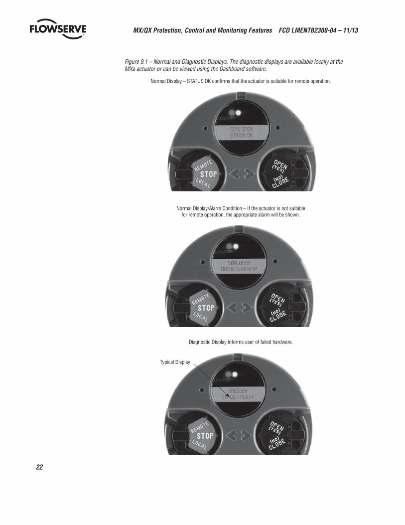
Figure 9.1 – Normal and Diagnostic Displays. The diagnostic displays are available locally at the MXa actuator or can be viewed using the Dashboard software.
Normal Display – STATUS OK confirms that the actuator is suitable for remote operation.
Normal Display/Alarm Condition – If the actuator is not suitable for remote operation, the appropriate alarm will be shown.
Diagnostic Display informs user of failed hardware.
Typical Display
23
MX/QX Protection, Control and Monitoring Features FCD LMENTB2300-04 – 11/13
flowserve.com
These features are available up to 10 meters from the actuator equipped with the Bluetooth option. Dashboard can also be used with the IrDA port supplied with each unit. It also requires a link to be established, but the effective communication distance is typically less than one meter to avoid cross-communication with neighboring devices.
Please refer to LMENIM2338 for the MX/QX Dashboard Installation, Operation, and Maintenance Manual (IOM).
10. Actuator Configuration10.1 Non-Intrusive Local ConfigurationMX/QX actuators may be configured without removing any covers, or using special tools. Configuration is accomplished through the use of the LCD, Dashboard software and the local control switches mounted on the Control Panel. Settings that can be initiated or changed include:
• Limit switch trip positions
• Torque output levels
• Direction of rotation
• Action on ESD
• External inhibits
• Remote control operating mode
• Motor thermostat action
• Stop valve on torque or position
• All optional features (Modutronic, DDC, FF H1, PB-DPV1 and redundant PB-DPV1, PB-PA, DeviceNet, Timers, APT, etc.)
10.2 Default ConfigurationUnless otherwise specified, MX/QX actuators will be shipped with the following configuration, which becomes effective after limits are set:
• Open stop by limit
• Close stop by limit
• Maintained local controls
• Clockwise to close
• ESD is “off” and set to “IGNORE.”
• Inhibits enabled, turned “OFF”
• Remote control – three-wire maintained and Multi-mode
• Password – 100
• Modutronic Option (if installed)
• QX Operating times – QX-1: default 15 sec; QX-2: default 30 sec; QX-3-5: default 60 sec
MX/QX Protection, Control and Monitoring Features FCD LMENTB2300-04 – 11/13
24
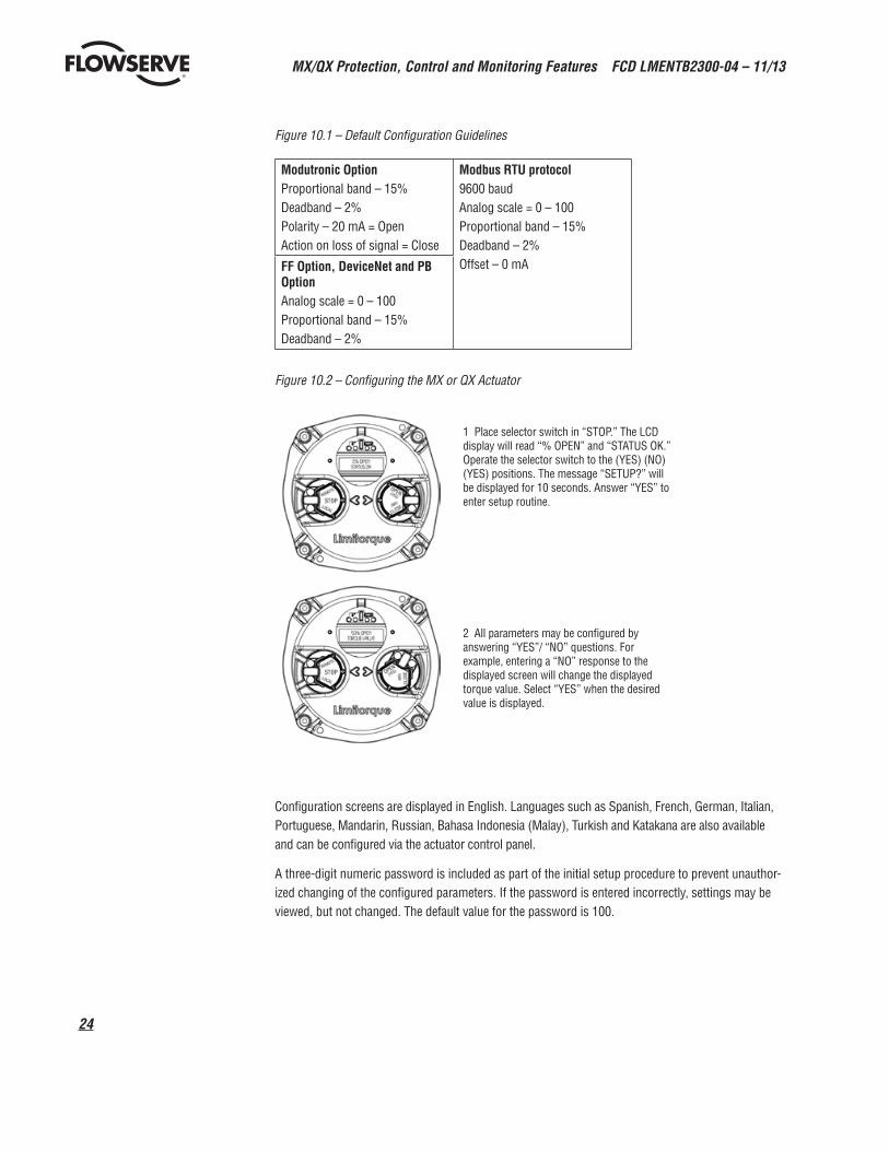
Figure 10.1 – Default Configuration Guidelines
Modutronic OptionProportional band – 15%Deadband – 2%Polarity – 20 mA = OpenAction on loss of signal = Close
Modbus RTU protocol9600 baudAnalog scale = 0 – 100Proportional band – 15%Deadband – 2%Offset – 0 mAFF Option, DeviceNet and PB
OptionAnalog scale = 0 – 100Proportional band – 15%Deadband – 2%
Figure 10.2 – Configuring the MX or QX Actuator
1 Place selector switch in “STOP.” The LCD display will read “% OPEN” and “STATUS OK.” Operate the selector switch to the (YES) (NO) (YES) positions. The message “SETUP?” will be displayed for 10 seconds. Answer “YES” to enter setup routine.
2 All parameters may be configured by answering “YES”/ “NO” questions. For example, entering a “NO” response to the displayed screen will change the displayed torque value. Select “YES” when the desired value is displayed.
Configuration screens are displayed in English. Languages such as Spanish, French, German, Italian, Portuguese, Mandarin, Russian, Bahasa Indonesia (Malay), Turkish and Katakana are also available and can be configured via the actuator control panel.
A three-digit numeric password is included as part of the initial setup procedure to prevent unauthor-ized changing of the configured parameters. If the password is entered incorrectly, settings may be viewed, but not changed. The default value for the password is 100.

25
MX/QX Protection, Control and Monitoring Features FCD LMENTB2300-04 – 11/13
flowserve.com
11. MX and QX SpecificationsThe MX and QX are the most rigorously tested non-intrusive actuators in the industry and they comply with all pertinent global requirements. Please contact the factory should your requirements exceed the listed parameters.
11.1 Global CertificationsStandard Non-hazardous certifications - The normal operating temperature range for weatherproof applications is from -30°C to +70°C (-22°F to +158°F). Options are available to -60°C (-76°F).
• FM – NEMA 3, 4, 4X and 6.
• CSA – Type 3, 4, and 6.
• IEC – IP 68 to 15 m for 96 hours for MX and 20 m for 168 hours for the QX.
• Submersion – NEMA 6 (6 ft–30 min), IEC529, IP68 (15 m–96 h for the MX and 20m–168 hours for the QX), Limitorque specification (20 ft–24 h)
• Saliferous (Salt) spray – 1500-hour test per ASTM B117-1985.
Standard Explosionproof certifications - The normal operating temperature range for explosionproof applications is from -30°C to +65°C (-22°F to +149°F). Options are available to -50°C (-57°F) for FM and CSA for the MX and FM Canada for the QX. For options below -50°C consult factory.
• FM – Class 1, Division 1, Group B, C, and D. Class II/III, Division 1, Group E, F, and G – T4
• CSA and FM Canada– Class 1, Division 1, Group C and D. Class II/III, Division 1, Group E, F, and G – T4
• ATEX – Eex d IIB T4 ATEX II 2 G, CENELEC Norm EN50014 and EN50018 (T6 for the QX)
• Eex d IIC T4 ATEX II 2 G, CENELEC Norm EN50014 and EN50018 (T6 for the QX)
• Eex de IIB T4 ATEX II 2 G, Increased Safety, CENELEC Norm EN50014, EN50018, EN50019 (T6 for the QX)
• Eex de IIC T4 ATEX II 2 G, Increased Safety, CENELEC Norm EN50014, EN50018, EN50019 (T6 for the QX)
• IECEx – Ex d IIB T4 & Ex de IIB T4 and Ex d IIC T4 & Ex de IIC T4 (MX only)
• IECEx – Eexd IIB T6 & Eexd IIC T6 and Eexde IIB T6 & Eexde IIC T6 (QX only)
11.2 Wiring• All internal wiring is flame resistant, rated -40°C to 105°C (-40°F to 221°F), and is UL listed.
11.3 Valve Interface• Mounting base conforms to MSS SP-102 or ISO 5210 as required. Steel torque bushings (type B)
and bronze thrust nuts (type A) are removable for machining.
11.4 Design Life and Endurance• Design Life - One million drive sleeve turns is considered typical life expectancy under normal
operating conditions in approved ambient working environments.
• Endurance – 50 million collective drive sleeve turns of endurance testing were performed on the MX for proof of design. The QX has been cycled better than 1 000 000 90-degree operations for proof of design.
• AWWA C540-02 – “Standard For Power Actuating Devices For Valves and Sluice Gates” – 5 000 cycles with confirmation of specified torque and position repeatability.
MX/QX Protection, Control and Monitoring Features FCD LMENTB2300-04 – 11/13
26
11.5 Diagnostic FeaturesDiagnostic facilities are displayed on the LCD by accessing the diagnostic menu or the MX/QX Dashboard™. Using Dashboard, the diagnostic information can be downloaded to a PC or PDA via both IRDA and optional Bluetooth ports. It includes: motor data (voltage, current, phase rotation, and temperature), hardware status, and identification (tag, serial order, and software revision), torque profile (comparison of last torque to baseline), and operations log (total turns, contactor operations, valve stroke time, and handwheel operations). Diagnostics also includes a restricted Frequency Domain Analysis (FDA) feature. The FDA methodology captures torque, position or speed values at regular time intervals while the actuator is motoring, and calculates the resulting data set with a Fast Fourier Transform (FFT). The resulting information can be used to isolate any components in the mechanical drive train that may exhibit excessive wear or may effect normal actuator operation. FDA and resultant fault indications can only be displayed via the Dashboard software.
11.6 Factory TestFactory testing verifies rated output torque, output speed, motor performance, handwheel opera-tion, local control, control power supply, control features, and baseline FDA. A report confirming successful completion of testing is included within the actuator.
11.7 Conduit Entries Three threaded conduit entries are provided for the MX; tapped: 1 x 1½" and 2 x 1¼" NPT. The actuator is available with 1 x M40 and 2 x M25 metric to BS3643, and PG adapters are available upon request. For the QX, two (2) 1.0" NPT and one (1) 1.25" NPT conduits are standard. Optional M25 or M32 adapters are available. An optional 1.0" or M25 conduit opening is also available.
11.8 European Directives All MX and QX actuator designs have been tested to comply with pertinent EU Directives and shipped with the Declaration of Conformity listed in the Regulatory Section of LMENIM2306 and LMENIM2314 for the MX and LMENIM3306 and LMENIM3314 for the QX. The actuator is also tagged with the CE mark to demonstrate compatibility with the following European Directives:
Directives 2006/142/EC – Machinery, 2004/108/EC – EMC – Electromagnetic Compatibility, 73/23/EC & 93/68/EC – Low Voltage, and 2003/10/EC Airborne Noise.
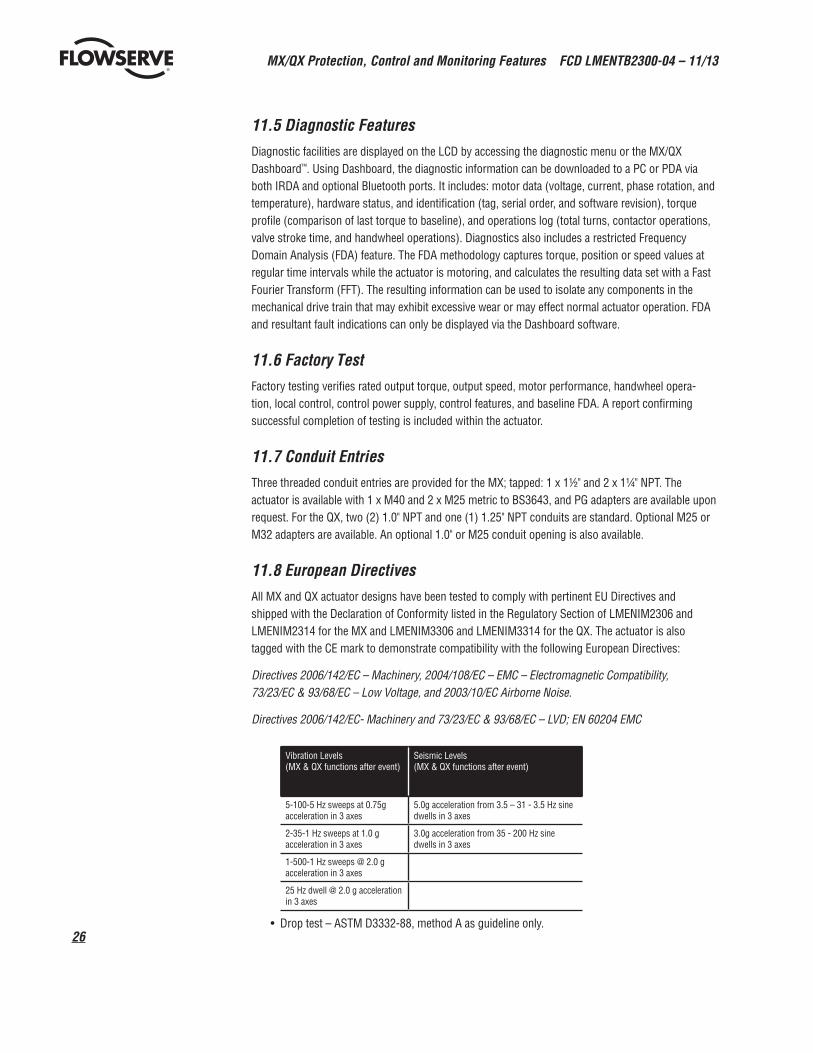
Directives 2006/142/EC- Machinery and 73/23/EC & 93/68/EC – LVD; EN 60204 EMC
Vibration Levels (MX & QX functions after event)
Seismic Levels (MX & QX functions after event)
5-100-5 Hz sweeps at 0.75g acceleration in 3 axes
5.0g acceleration from 3.5 – 31 - 3.5 Hz sine dwells in 3 axes
2-35-1 Hz sweeps at 1.0 g acceleration in 3 axes
3.0g acceleration from 35 - 200 Hz sine dwells in 3 axes
1-500-1 Hz sweeps @ 2.0 g acceleration in 3 axes
25 Hz dwell @ 2.0 g acceleration in 3 axes
• Drop test – ASTM D3332-88, method A as guideline only.
27
MX/QX Protection, Control and Monitoring Features FCD LMENTB2300-04 – 11/13
flowserve.com
• Temperature extremes with humidity – Confirm function of motor, controls, and output torque at -30°C (-22°F) for 72 hours continuous, 70°C (158°F) dry heat for 16 hours continuous and 70°C (158°F) damp heat for 72 hours continuous. The actuators have also been subjected to arctic extremes down to -60°C (76°F) and maximum temperatures to 40°C (+104°F). The maximum temperature is limited by the lubrication viscosity.
• Di-electric – Motor per NEMA MG1-12.02 and .03 with leakage of less than 10 mA. Control terminals per IEC-1131-2 and CSA C22.2 with check against physical breakdown.
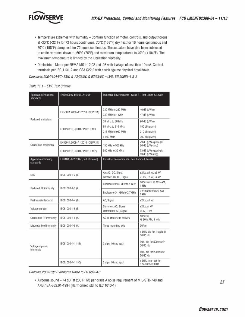
Directives 2004/104/EC- EMC & 73/23/EC & 93/68/EC – LVD; EN 50081-1 & 2 Table 11.1 – EMC Test Criteria
Applicable Emissions standards
EN61000-6-4:2007+A1:2011 Industrial Environments - Class A - Test Limits & Levels
Radiated emissions
EN55011:2009+A1:2010 (CISPR11)330 MHz to 230 MHz
230 MHz to 1 GHz
40 dB (μV/m)
47 dB (μV/m)
FCC Part 15, (CFR47 Part 15.109
30 MHz to 88 MHz
88 MHz to 216 MHz
216 MHz to 960 MHz
> 960 MHz
90 dB (μV/m)
150 dB (μV/m)
210 dB (μV/m)
300 dB (μV/m)
Conducted emissionsEN55011:2009+A1:2010 (CISPR11)
150 kHz to 500 kHz
500 kHz to 30 MHz
79 dB (μV) (quasi-pk), 66 dB (μV) (avg)
73 dB (μV) (quasi-pk), 60 dB (μV) (avg)
FCC Part 15, (CFR47 Part 15.107)
Applicable immunity standards
EN61000-6-2:2005 (Perf. Criteron) Industrial Environments - Test Limits & Levels
ESD IEC61000-4-2 (B)Air: AC, DC, Signal
Contact: AC, DC, Signal
±2 kV, ±4 kV, ±8 kV
±1 kV, ±2 kV, ±4 kV
Radiated RF immunity IEC61000-4-3 (A)Enclosure @ 80 MHz to 1 GHz 10 Vrms/m @ 80% AM,
1 kHz
Enclosure @ 1 GHz to 2.7 GHz 3 Vrms/m @ 80% AM, 1 kHz
Fast transients/burst IEC61000-4-4 (B) AC, Signal ±2 kV, ±1 kV
Voltage surges IEC61000-4-5 (B)Common: AC, Signal
Differential: AC, Signal
±2 kV, ±l kV
±l kV, ±l kV
Conducted RF immunity IEC61000-4-6 (A) AC @ 150 kHz to 80 MHz 10 Vrms @ 80% AM, 1 kHz
Magnetic field immunity IEC61000-4-8 (A) Three mounting axis 30A/m
Voltage dips and interrupts
IEC61000-4-11 (B) 3 dips, 10 sec apart
> 95% dip for 1 cycle @ 50/60 Hz
30% dip for 500 ms @ 50/60 Hz
60% dip for 200 ms @ 50/60 Hz
IEC61000-4-11 (C) 3 dips, 10 sec apart > 95% interrupt for 5 sec @ 50/60 Hz
Directive 2003/10/EC Airborne Noise to EN 60204-1
• Airborne sound – 74 dB (at 200 RPM) per grade A noise requirement of MIL-STD-740 and ANSI/ISA-S82.01-1994 (Harmonized std. to IEC 1010-1).

MX/QX Protection, Control and Monitoring Features FCD LMENTB2300-04 – 11/13
28
12. Wiring Configurations for the MX and QXFigure 12.1 – MX/QX Terminal Block
GROUNDINGLUG
NETWORK GROUNDINGLUGS
12.1 MX/QX Terminal BlockThe standard terminal block for the MX/QX now has 54 points and can sustain all of the options for the MX/QX.
Grounding (earth) lugs are provided for both power leads and network control. It is recommended that the machined areas adjacent to the terminal block be used to properly ground any network applications.
12.2 Wiring Diagram Configurator The MX and QX feature a number of flexible options that permit a user to customize the electronic actuator for very specific field applications. A wiring diagram configurator is available on-line at www.flowserve-wiring.com. This configurator permits a User to select the options for their specific application and print either in a Adobe Acrobat PDF version, or in a Autodesk DXF version.
The relay options can be ordered for a new actuator or added to an existing MX/QX and are listed as follows:
• OS = Standard S relays (4 total, 2 configurable, 2 complementary) and (1) Monitor, rated for 2 A/30VDC, 0.5 A/125 VAC
• OA = Digital output R option (4), including Monitor, rated for 1 A/50 VDC or 5 A/30 VDC, 250 VAC
• OB = Standard S relays (2), including Monitor, rated for 2 A/30 VDC, 0.5 A/125 VAC and Digital output R option (4), rated for 1 A/50 VDC or 5 A/30 VDC, 250 VAC
• OC = Digital output R2 option (8), including Monitor, rated for 1 A/50 VDC or 5 A/30 VDC, 250 VAC
29
MX/QX Protection, Control and Monitoring Features FCD LMENTB2300-04 – 11/13
flowserve.com
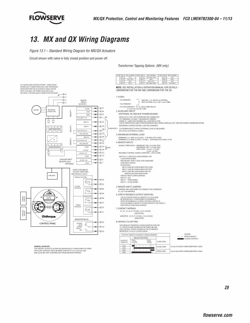
13. MX and QX Wiring DiagramsFigure 13.1 – Standard Wiring Diagram for MX/QX Actuators
Circuit shown with valve in fully closed position and power off.
Transformer Tapping Options (MX only)
REVERSINGCONTACTOR
CLOSE
STOP
OPEN
DIG COM #2-Ve
AUXILIARY INPUTSEE NOTE 2 &10
0 VAC
110 VAC
24 VDC +Ve
0 VDC
24 VDC +Ve
0 VDC
27
26
25
35
28
29
34
24
21
22
7
6
L1
L2
L3
LIMIGARD
45
48
49
46
47
50
51
S1a
S1b
S2a
S2b
"CLOSE"POSITION
"OPEN"POSITION
54
53
52
SHOWNWITH
POWERSUPPLY
OFF
CONTROL PANEL
MOTOR
1. FUSES
FSI (PRIMARY)
FS2 (PRIMARY)
3. MAXIMUM EXTERNAL LOADTERMINALS 21 AND 22 (24 VDC) - 5 W MAX. EXT. LOADTERMINALS 23 AND 24 (OPT. 110 VAC) - 20 W MAX EXT. LOAD, 15 VA
REQUIRED CONTROL SIGNAL DURATION = 350 ms MIN.
6. STATUS FEEDBACK OUTPUT SWITCHESTHE ACTUATOR STATUS CONTACTS (S1 & S2) MAYBE INDIVIDUALLY CONFIGURED AS NORMALLY
OR AS BLINKER CONTACTS, PLEASE REFER TO SECTION 5.1 FOR STATUS FUNCTION CHOICES.
PE
ACTUATOR USER SUPPLIED POWER - THREE PHASE SHOWN, BUT CONNECTIONS WILL VARY DEPENDING UPON WHETHER THE ACTUATOR IS SINGLE PHASE OR DC (QX ONLY) OR THREE PHASE (MX & QX). SEE PAGE 4 FOR AVAILABLE CONNECTION VOLTAGES.
7. CONTACT RATINGS
TOR
QU
ESE
NSO
RP
OSI
TIO
NSE
NSO
R
MONITOR RELAY
OPEN OR NORMALLY CLOSED LATCHED CONTACTS,
BACK-UP 24 VDC UPS POWER MAY BE CONNECTEDTO TERMINAL'S 6 AND 7. MAXIMUM CURRENTDRAW IS 1 AMP. THIS POWERS ALL CONTROLS FOR
REVERSING CONTACTOR WILL NOT BE POWERED.
CUSTOMER MUST SUPPLY EXTERNAL FUSE AS REQUIRED
2. AUXILIARY INPUT
600 VAC, 1 A, 200 kA Int RATING,FAST ACTING 10.3 x 38.1 mm TUBE.
FS3 (SECONDARY) - 0.1 A, 250 V, TIME DELAY, 5 x 20 mm, GLASS TUBE
S1, S2 - 0.5 A @ 125 VAC, 2 A @ 30 VDC
MONITOR - 0.5 A @ 125 VAC, 2 A @ 30 VDC
STATUS FEEDBACKOUTPUT SWITCHES
SEE NOTES 6,7,8 & 9
DEFAULT SETTING
32
30
DIG COM #1-Ve
DIG COM #3-Ve
2 mA / 24 VDCMAX LOAD - 10 mA / 110 VACMAXIMUM "OFF" 5.0 VAC/VDC
SIGNAL THRESHOLD - MINIMUM "ON" 19.2 VAC/VDC
4. REMOTE INPUTS
INPUT 2
INPUT 1
INPUT 0
44
23
DIG COM #2A 31
DIG COM #3A 33
}OPT.
(OPTIONAL)
JUMPERS ARE USER WIRED TO CONNECT DIG COMMONS#1, 2 & 3 (AS NEEDED).
(OPTIONAL W/ BACKUP POWER BOARD)
(RESISTIVE)
(RESISTIVE)
5. REMOTE INPUT JUMPERS
SEE NOTE 5
BY LOCAL ELECTRICAL CODES.
GR
OU
P 1
GR
OU
P 2
GR
OU
P 3
REMOTEINPUTS
SEE NOTE 4
LOCAL INDICATION AND CONFIGURATION, INCLUDING ANALOG OUT AND NETWORK COMMUNICATION.
8. DEFAULT [S] SETTING
THE DEFAULT OPERATING CONFIGURATION FOR THE"S" OUTPUTS ARE SHOWN IN THE TABLE BELOW.THE CONTACT STATES SHOWN IN THE SCHEMATICREPRESENT A FULLY CLOSED VALVE.
OUTPUT SWITCH CONTACT DEVELOPMENT
VALVE POSITION
FULLCLOSE
FULLOPEN FUNCTION
CLOSE LIMIT
S2bOPEN LIMIT
S2a
S1aS1b
OUTPUTSWITCH
S1a & S1b HAVE COMPLEMENTARY LOGIC
S2a & S2b HAVE COMPLEMENTARY LOGIC
LEGENDOPEN CONTACTCLOSED CONTACT
0% OPENSTATUS OK
INPUTS 0,1,2 ARE FIELD CONFIGURABLE FOR CLOSE/OPEN INHIBIT, REDUNDANT OPEN, CLOSE, STOP [LIMIGARD] USER INPUT, OR ESD. IN ADDITION, INPUT 0 MAY BE CONFIGURED FOR CLOSE; INPUT 1 MAY BE CONFIGURED FOR STOP; INPUT 2 MAY BE CONFIGURED FOR CSE REMOTE SELETION INDICATION: DEFAULT INPUT CONFIGURATION: INPUT 0 - ESD, INPUT 1 - OPEN INHIBIT, INPUT 2 - CLOSE INHIBIT
DIGITAL OUTPUTSTHE DIGITAL OUTPUTS (S) MAY BE INDIVIDUALLY CONFIGURED AS OPEN OR CLOSE LATCHED, OR AS BLINKER CONTACTS. S1a, S1b, S2a, S2b, MAY ALSO BE “DDC CONTROLLED” FROM MASTER STATION.
TYPE TAPS APPL. VOLTAGES TYPE TAPS APPL. VOLTAGES TYPE TAPS APPL. VOLTAGES
1
106 V 110 V
2
226 V 226 V, 260 V, 240 V
3
212 V 220 V
115 V 115 V, 120 V 366 V 380 V 505 V 525 V
200 V 208 V 392 V 400 V, 415 V 530 V 550 V
220 V 220 V 450 V 440 V, 460 V, 480 V 572 V 575 V, 600 V
NOTE: SEE INSTALLATION & OPERATION MANUAL FOR DETAILS – LMENIM2306 FOR THE MX AND LMENIM3306 FOR THE QX
CONTROL PANEL
0% OPENSTATUS OK
OPEN
CLOSE
(YES)
(NO)
REMOTE
LOCAL
MX/QX Protection, Control and Monitoring Features FCD LMENTB2300-04 – 11/13
30
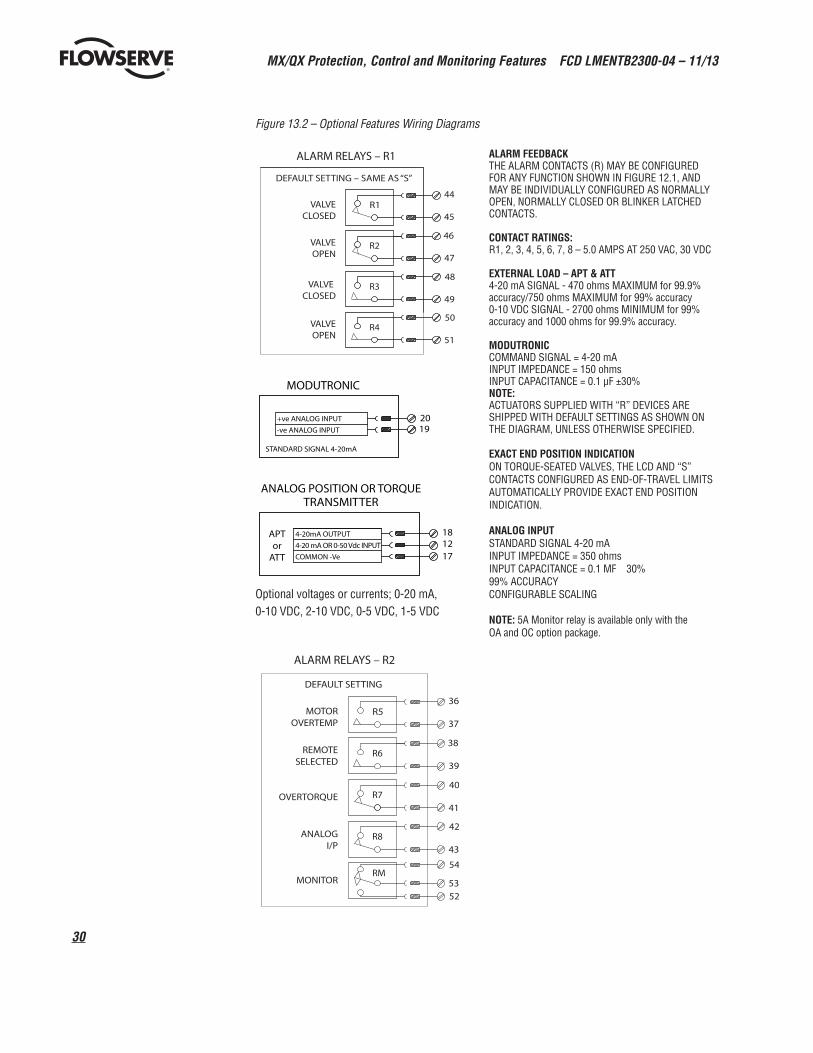
Figure 13.2 – Optional Features Wiring Diagrams
ALARM FEEDBACKTHE ALARM CONTACTS (R) MAY BE CONFIGURED FOR ANY FUNCTION SHOWN IN FIGURE 12.1, AND MAY BE INDIVIDUALLY CONFIGURED AS NORMALLY OPEN, NORMALLY CLOSED OR BLINKER LATCHED CONTACTS.
CONTACT RATINGS:R1, 2, 3, 4, 5, 6, 7, 8 – 5.0 AMPS AT 250 VAC, 30 VDC
EXTERNAL LOAD – APT & ATT4-20 mA SIGNAL - 470 ohms MAXIMUM for 99.9% accuracy/750 ohms MAXIMUM for 99% accuracy0-10 VDC SIGNAL - 2700 ohms MINIMUM for 99% accuracy and 1000 ohms for 99.9% accuracy.
MODUTRONICCOMMAND SIGNAL = 4-20 mAINPUT IMPEDANCE = 150 ohmsINPUT CAPACITANCE = 0.1 µF ±30%NOTE:ACTUATORS SUPPLIED WITH “R” DEVICES ARE SHIPPED WITH DEFAULT SETTINGS AS SHOWN ON THE DIAGRAM, UNLESS OTHERWISE SPECIFIED.
EXACT END POSITION INDICATIONON TORQUE-SEATED VALVES, THE LCD AND “S” CONTACTS CONFIGURED AS END-OF-TRAVEL LIMITS AUTOMATICALLY PROVIDE EXACT END POSITION INDICATION.
ANALOG INPUTSTANDARD SIGNAL 4-20 mAINPUT IMPEDANCE = 350 ohmsINPUT CAPACITANCE = 0.1 MF 30% 99% ACCURACYCONFIGURABLE SCALING
NOTE: 5A Monitor relay is available only with the OA and OC option package.
42
43R8
DEFAULT SETTING
ALARM RELAYS – R2
MOTOROVERTEMP
REMOTESELECTED
OVERTORQUE
MONITOR
ANALOGI/P
R7
R6
R537
36
39
38
41
40
54
53RM
52
MODUTRONIC
STANDARD SIGNAL 4-20mA
1920
-ve ANALOG INPUT
+ve ANALOG INPUT
18
17
APTor
ATT
12
ANALOG POSITION OR TORQUETRANSMITTER
16
1ATT
4-20mA OUTPUT
0-10VDC OUTPUT
COMMON -Ve
2
ANALOG TORQUETRANSMITTER
4-20mA OUTPUT
4-20 mA OR 0-50 Vdc INPUT
COMMON -Ve
50
51R4
DEFAULT SETTING – SAME AS “S”
ALARM RELAYS – R1
VALVECLOSED
VALVEOPEN
VALVE CLOSED
VALVEOPEN
R3
R2
R145
44
47
46
49
48
Optional voltages or currents; 0-20 mA, 0-10 VDC, 2-10 VDC, 0-5 VDC, 1-5 VDC
31
MX/QX Protection, Control and Monitoring Features FCD LMENTB2300-04 – 11/13
flowserve.com
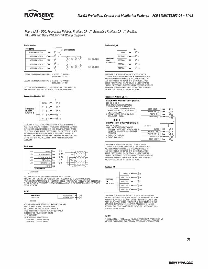
Figure 13.3 – DDC, Foundation Fieldbus, Profibus DP_V1, Redundant Profibus DP_V1, Profibus PA, HART and DeviceNet Network Wiring Diagrams
RECOMMENDED DEVICENET CABLE IS BELDEN 3084A OR EQUAL.120 OHM, 1/4W TERMINATION RESISTORS MUST BE CONNECTED AT EACH SEGMENT END.PREFERRED NETWORK WIRING IS TO CONNECT SHIELD TO TERMINAL 3 FOR EVERY UNIT ON SEGMENT. SHIELD SHOULD BE CONNECTED TO POWER SUPPLY GROUND AT THE CLOSEST POINT IN THE CENTER OF THE NETWORK.
NOMINAL ANALOG INPUT CURRENT 4 – 20mA, 30mA MAX.ANALOG INPUT SIGNAL LOAD – 300 OHMS.SET JUMPERS JP1 AND JP2 TO POSITION 1– 2.THE 3 – PIN CONNECTOR WITH BLUE WIRES SHOULDBE CONNECTED TO J3 ON HART BOARD.(J1 IS NOT USED)HART TERMINAL CONNECTIONS: TERMINAL 12 ––––– LOOP(+) TERMINAL 17 ––––– LOOP(-)
DeviceNet
HART
DEVICENET BOARD
EGND
RED
WHTBLK
BLU
5
4NETWORK 0V
NETWORK +24V
ANALOG INPUT 1217COMMON – Ve
NETWORK DATA (–)
NETWORK DATA (+)
SHIELD
HART BOARD(SEE NOTE 6)
3
13
14J8.5
J8.1
J8.3
J8.4
J8.2
VIA STANDOFF
BLU
WHTBLK
RED
N/C
LOSS OF COMMUNICATION ON A1 => REGISTER 9 CHANNEL A (BIT 0x0400) SET TO 1
LOSS OF COMMUNICATION ON A2 => REGISTER 9 CHANNEL B (BIT 0x0800) SET TO 1
PREFERRED NETWORK WIRING IS TO CONNECT ONLY ONE SHIELD TO EARTH/GROUND. REFER TO DDC INSTALLATION DOCUMENTATION.
14
13
3
4
5
NETWORK DATA-A2
NETWORK DATA-A2*
NETWORK DATA-A1
NETWORK DATA-A1*
DDC BOARD
DDC – Modbus
EARTH/GROUNDSURGE PROTECTION
AREG 9.0x0400
REG 9.0x0800B
CUSTOMER IS REQUIRED TO CONNECT WIRE BETWEEN TERMINAL 3 AND CHASIS GROUND FOR SURGE PROTECTION. PREFERRED NETWORK WIRING IS TO CONNECT SHIELD TO EARTH/GROUND AT BOTH ENDS OF THE SEGMENT. ATTACH SHIELD TO TERMINAL 3 ONLY IF DEVICE IS LOCATED AT THE ENDS OF THE SEGMENT. CUSTOMER MUST CONNECT REMAINING INDIVIDUAL NETWORK CABLE SHIELDS TOGETHER TO ENSURE PROPER SHIELDING OF THE ENTIRE NETWORK.
14
13
3
4
5PBDP1 (+)
PBDP1 (–)PROFIBUS DPV1 IEC 61158–2
Profibus DP_V1
Redundant Profibus DP_V1
CUSTOMER IS REQUIRED TO CONNECT WIRE BETWEEN TERMINAL 3 AND CHASIS GROUND FOR SURGE PROTECTION. PREFERRED NETWORK WIRING IS TO CONNECT SHIELD TO EARTH/GROUND AT BOTH ENDS OF THE SEGMENT. ATTACH SHIELD TO TERMINAL 3 ONLY IF DEVICE IS LOCATED AT THE ENDS OF THE SEGMENT. CUSTOMER MUST CONNECT REMAINING INDIVIDUAL NETWORK CABLE SHIELDS TOGETHER TO ENSURE PROPER SHIELDING OF THE ENTIRE NETWORK.
SURGE
CUSTOMER IS REQUIRED TO CONNECT WIRE BETWEEN TERMINAL 3 AND CHASIS GROUND FOR SURGE PROTECTION. PREFERRED NETWORK WIRING IS TO CONNECT SEGMENT SHIELD TO EARTH/GROUND AT ONE POINT ONLY. ATTACH SHIELD TO TERMINAL 3 ONLY IF SEGMENT IS NOT GROUNDED. ELSEWHERE, CUSTOMER MUST CONNECT INDIVIDUAL NETWORK CABLE SHIELDS TOGETHER TO ENSURE PROPER SHIELDING OF THE ENTIRE NETWORK. CURRENT DRAW FOR FF BOARD 24 mA MAXIMUM.
14
13
3
4
5
FF1 (+)
FF1 (–)
FF1 (+)
FF1 (–)FOUNDATION FIELDBUS IEC 61158–2
Foundation Fieldbus_H1
SURGE
TERMINALS 13 &14 FOR FOUNDATION FIELDBUS, PROFIBUS PA, PROFIBUS DP_V1 ARE USED FOR CHANNEL B ON OPTIONAL REDUNDANT NETWORK BOARD.
NOTES:
CUSTOMER IS REQUIRED TO CONNECT WIRE BETWEEN TERMINAL 3 AND CHASIS GROUND FOR SURGE PROTECTION. PREFERRED NETWORK WIRING IS TO CONNECT SEGMENT SHIELD TO EARTH/GROUND AT ONE POINT ONLY. ATTACH SHIELD TO TERMINAL 3 ONY IF SEGMENT IS NOT GROUNDED. ELSEWHERE, CUSTOMER MUST CONNECT INDIVIDUAL NETWORK CABLE SHIELDS TOGETHER TO ENSURE PROPER SHIELDING OF THE ENTIRE NETWORK.
14
13
3
4
5
PBPA1 (+)
PBPA1 (–)
PBPA1 (+)
PBPA1 (–)PROFIBUSPAIEC 61158–2
Profibus_PA
SURGE
PBDP1 (+)
PBDP1 (–)
PBDP-A OUT (+)PBDP-A OUT (-)
SEE NOTES
3
14
13
45
PBDP-A IN (+)PBDP-A IN (-)
PER IEC 61158-2
REDUNDANT PROFIBUS DPV1 (BOARD 2)
PBDP-B OUT (+)PBDP-B OUT (-)
15
16
12
PBDP-B IN (+)PBDP-B IN (-)
PER IEC 61158-2
SINGLE MASTER REDUNDANCY NOTES:1. FOR SINGLE MASTER REDUNDANCY, JUMPER
13/14 FROM BOARD 1 TO 16/15 ON BOARD 2,
2. DATA IN ON 13 AND 14.3. DATA OUT ON 4 AND 5.
DUAL MASTER REDUNDANCY NOTES:1. FOR DUAL MASTER REDUNDANCY,
DO NOT INSTALL JUMPERS AS SHOWN.2. FOR INTERFACE 1; DATA IN ON 13 AND 14,
DATA OUT ON 4 AND 5.3. FOR INTERFACE 2; DATA IN ON 16 AND 15,
DATA OUT ON 1 AND 2.
AS SHOWN.
PRIMARY PROFIBUS DPV1 (BOARD 1)
SURGE
MX/QX Protection, Control and Monitoring Features FCD LMENTB2300-04 – 11/13
32
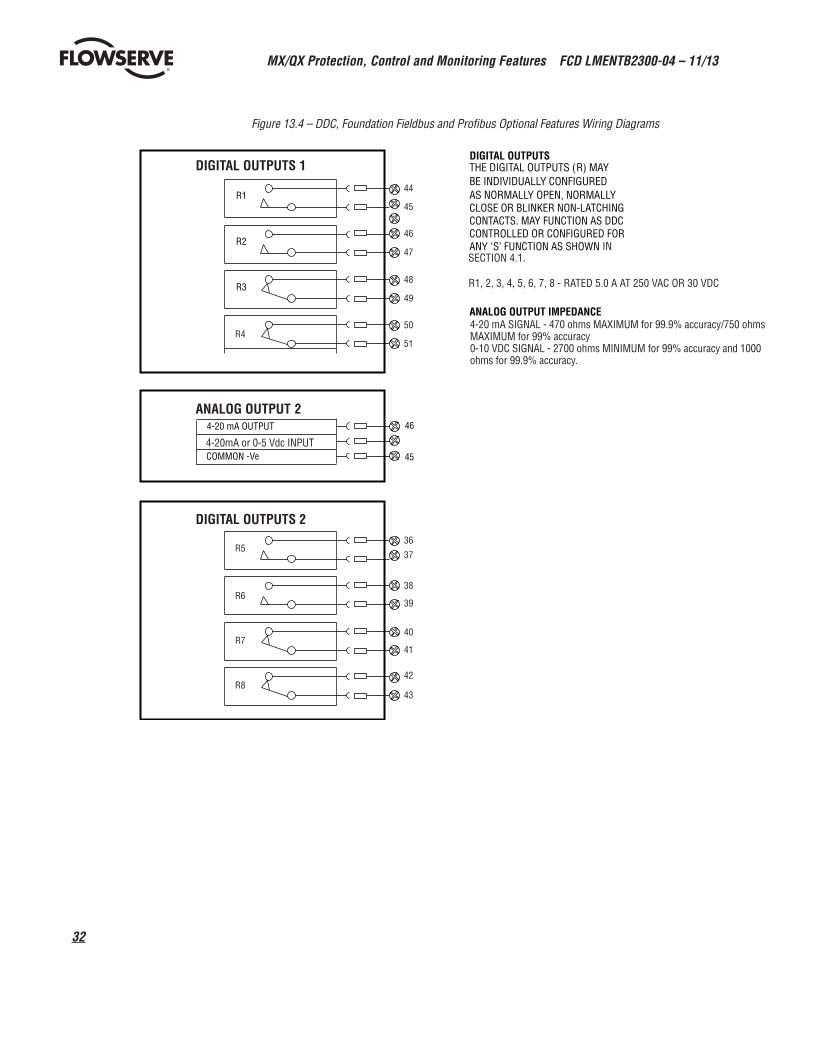
Figure 13.4 – DDC, Foundation Fieldbus and Profibus Optional Features Wiring Diagrams
R1, 2, 3, 4, 5, 6, 7, 8 - RATED 5.0 A AT 250 VAC OR 30 VDC
ANALOG OUTPUT 1
DIGITAL OUTPUTS 2
DIGITAL OUTPUTS 1
DIGITAL INPUTS 24 VDC
36R5
R4
R6
R7
R8
37
38
39
40
41
42
43
44
45
46
47
48
49
50
51
1-4
2
4-20mA or 0-5 Vdc INPUT
4-20 mA SIGNAL - 470 ohms MAXIMUM for 99.9% accuracy/750 ohms MAXIMUM for 99% accuracy0-10 VDC SIGNAL - 2700 ohms MINIMUM for 99% accuracy and 1000 ohms for 99.9% accuracy.
33
MX/QX Protection, Control and Monitoring Features FCD LMENTB2300-04 – 11/13
flowserve.com
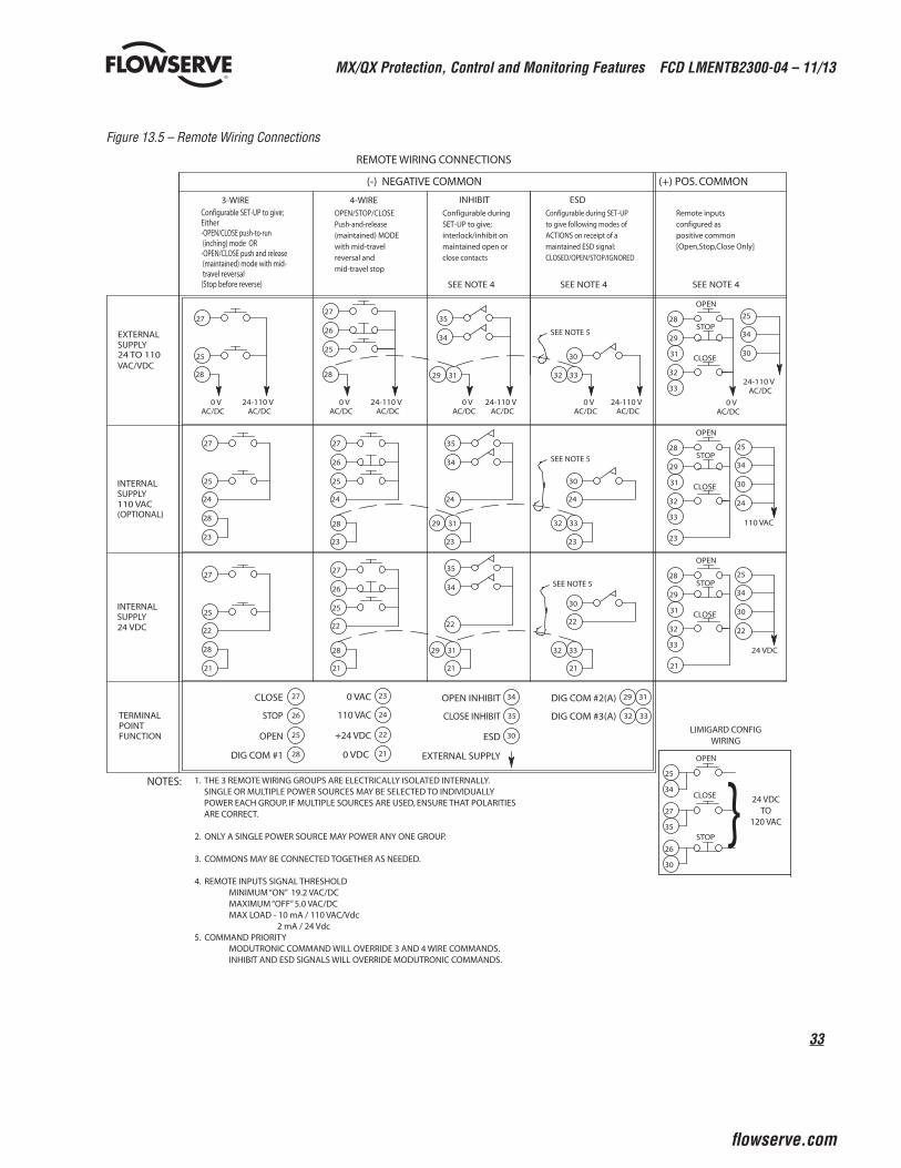
Figure 13.5 – Remote Wiring Connections REMOTE WIRING CONNECTIONS
CLOSE
STOP
OPEN
CLOSE
STOP
OPEN
CLOSE
STOP
OPEN
SEE NOTE 5
SEE NOTE 5
SEE NOTE 5
[Open,Stop,Close Only]
3229
3229
29 32
33
31 30
34
24 VDC
25
32
29
28
21
22
24
23
28
29
32
25
110 VAC
34
3031
33
33
31 30
34
AC/DC24-110 V
AC/DC0 V
25
32
29
28
SEE NOTE 4
positive commonconfigured asRemote inputs
(+) POS. COMMON(-) NEGATIVE COMMON
SEE NOTE 4SEE NOTE 4
3-WIRE 4-WIRE INHIBIT ESD
27
25
27
26
25
35
34
30
28
27
25
24
28
23
27
26
25
33
24
28
23
27
25
22
28
21
27
26
25
22
28
21
3128
35
34
30
2424
35
34
30
2222
31
21
33
21
CLOSE
STOP
OPEN
DIG COM #1
27
26
25
28
0 VAC
110 VAC
+24 VDC
0 VDC
23
24
22
21
33
23
31
23
0 VAC/DC
24-110 VAC/DC
0 VAC/DC
24-110 VAC/DC
0 VAC/DC
24-110 VAC/DC
0 VAC/DC
24-110 VAC/DC
OPEN INHIBIT
CLOSE INHIBIT
ESD
EXTERNAL SUPPLY
34
35
30
Configurable SET-UP to give;Either-OPEN/CLOSE push-to-run (inching) mode OR-OPEN/CLOSE push and release (maintained) mode with mid- travel reversal(Stop before reverse)
OPEN/STOP/CLOSEPush-and-release(maintained) MODEwith mid-travelreversal andmid-travel stop
Configurable duringSET-UP to give;interlock/inhibit onmaintained open orclose contacts
Configurable during SET-UPto give following modes ofACTIONS on receipt of amaintained ESD signal:CLOSED/OPEN/STOP/IGNORED
(OPTIONAL)
INTERNALSUPPLY24 VDC
INTERNALSUPPLY110 VAC
TERMINALPOINT
EXTERNALSUPPLY24 TO 110VAC/VDC
FUNCTION
DIG COM #2(A)
DIG COM #3(A)
29
32 33
31
26
27
25
34
35
30
}OPEN
CLOSE
STOP
1. THE 3 REMOTE WIRING GROUPS ARE ELECTRICALLY ISOLATED INTERNALLY.SINGLE OR MULTIPLE POWER SOURCES MAY BE SELECTED TO INDIVIDUALLY POWER EACH GROUP. IF MULTIPLE SOURCES ARE USED, ENSURE THAT POLARITIES ARE CORRECT.
2. ONLY A SINGLE POWER SOURCE MAY POWER ANY ONE GROUP.
3. COMMONS MAY BE CONNECTED TOGETHER AS NEEDED.
4. REMOTE INPUTS SIGNAL THRESHOLD MINIMUM “ON” 19.2 VAC/DC MAXIMUM “OFF” 5.0 VAC/DC MAX LOAD - 10 mA / 110 VAC/Vdc 2 mA / 24 Vdc5. COMMAND PRIORITY MODUTRONIC COMMAND WILL OVERRIDE 3 AND 4 WIRE COMMANDS. INHIBIT AND ESD SIGNALS WILL OVERRIDE MODUTRONIC COMMANDS.
24 VDCTO
120 VAC
LIMIGARD CONFIGWIRING
NOTES:

MX/QX Protection, Control and Monitoring Features FCD LMENTB2300-04 – 11/13
34
14. Network Protocol Connections14.1 Network Wiring — DDC-ModbusPlease consult LMENIM2329 for detailed installation instructions.
• Belden 3105A Specifications
Total cable length between repeaters or nodes with repeaters:
• @ 9.6 kbps: 11500 ft. (3.5 km)
• @ 19.2 kbps: 5750 ft. (1.7 km)
Key Specifications
• Resistance/1000 ft = 22 AWG (7 x 30) 14.7 ohms each conductor (29.4 ohms for the pair)
• Capacitance/ft. = 11.0 pF (conductor-to-conductor)
• Capacitance/ft. = 20.0 pF (conductor-to-shield)
• Belden 3074F specifications
Total cable length between repeaters or nodes with repeaters:
• @ 9.6 kbps: 15000 ft. (4.5 km)
• @ 19.2 kbps: 7500 ft. (2.2 km)
Key Specifications
• Resistance/1000 ft = 18 AWG (7x26) 6.92 ohms each conductor (13.84 ohms for the pair)
• Capacitance/ft. = 14 pF (conductor-to-conductor)
• Capacitance/ft. = 14 pF (conductor-to-shield)
•Belden9841specifications
Total cable length between repeaters or nodes with repeaters:
• @ 9.6 kbps: 6560 ft (2 km)
• @ 19.2 kbps: 3300 ft. (1 km)
Key Specifications
• Resistance/1000 ft = 24 AWG (7 x 32)
24 ohms each conductor (48 ohms for the pair)
• Capacitance/ft. = 12.8 pF (conductor-to-conductor)
• Capacitance/ft. = 23 pF (conductor-to-shield)
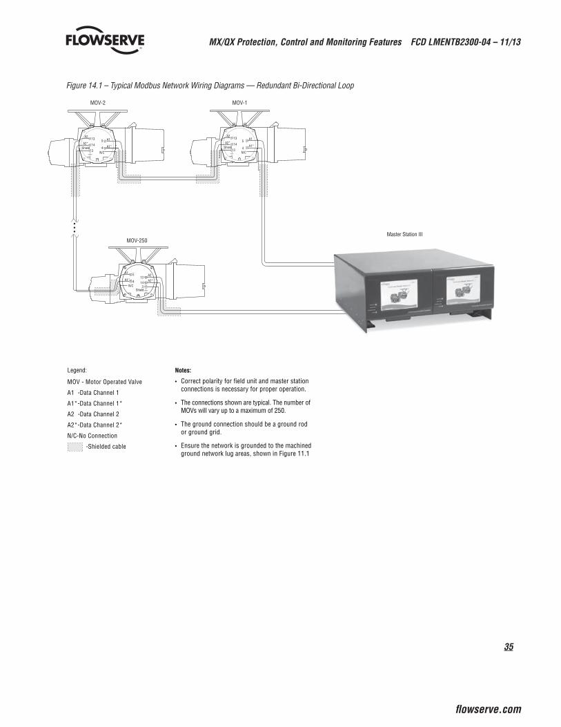
35
MX/QX Protection, Control and Monitoring Features FCD LMENTB2300-04 – 11/13
flowserve.com
Figure 14.1 – Typical Modbus Network Wiring Diagrams — Redundant Bi-Directional Loop
MOV-250
MOV-2 MOV-
Master Station III
1
13
14
A1
A1*
Shield
514
A2
A2*
4
A1
A1*3
13
Shield
514
A2
A2*4
A1
A1*3
13
ShieldN/C
5
4
3
A2
A2*
N/C
N/C
•••
Legend:
MOV - Motor Operated V alve
A1 - Data Channel 1
A1*- Data Channel 1*
A2 - Data Channel 2
A2*- Data Channel 2*
N/C -No Connection
- Shielded cable
Notes:
• Correct polarity for field unit and master station connections is necessary for proper operation.
• The connections shown are typical. The number of MOVs will vary up to a maximum of 250.
• The ground connection should be a ground rod or ground grid.
• Ensure the network is grounded to the machined ground network lug areas, shown in Figure 11.1
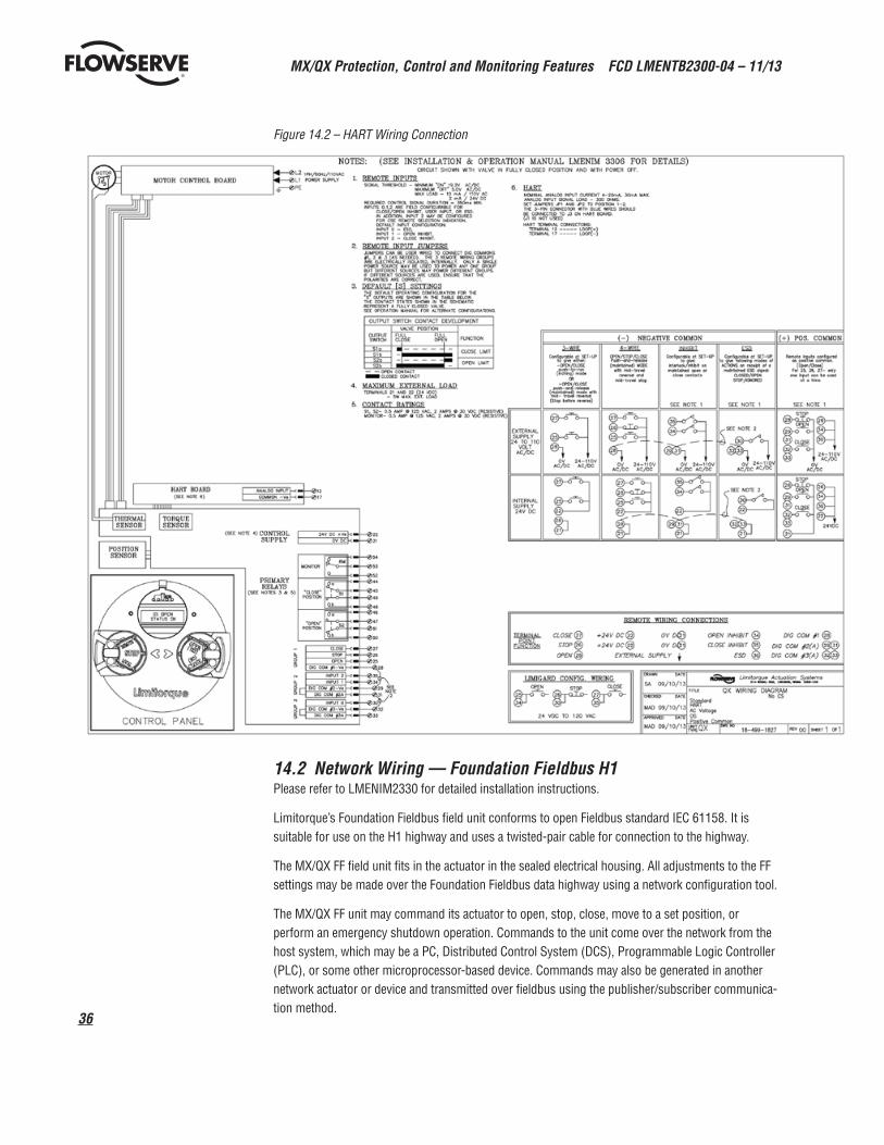
MX/QX Protection, Control and Monitoring Features FCD LMENTB2300-04 – 11/13
36
Figure 14.2 – HART Wiring Connection
14.2 Network Wiring — Foundation Fieldbus H1Please refer to LMENIM2330 for detailed installation instructions.
Limitorque’s Foundation Fieldbus field unit conforms to open Fieldbus standard IEC 61158. It is suitable for use on the H1 highway and uses a twisted-pair cable for connection to the highway.
The MX/QX FF field unit fits in the actuator in the sealed electrical housing. All adjustments to the FF settings may be made over the Foundation Fieldbus data highway using a network configuration tool.
The MX/QX FF unit may command its actuator to open, stop, close, move to a set position, or perform an emergency shutdown operation. Commands to the unit come over the network from the host system, which may be a PC, Distributed Control System (DCS), Programmable Logic Controller (PLC), or some other microprocessor-based device. Commands may also be generated in another network actuator or device and transmitted over fieldbus using the publisher/subscriber communica-tion method.
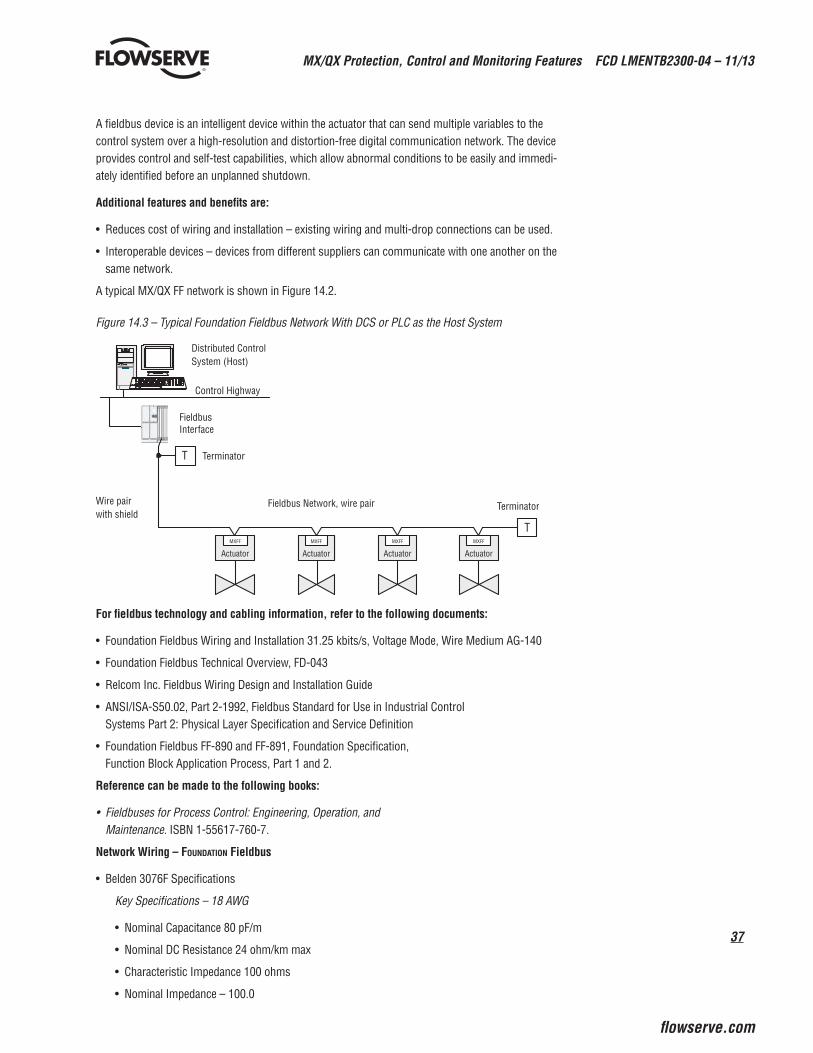
37
MX/QX Protection, Control and Monitoring Features FCD LMENTB2300-04 – 11/13
flowserve.com
A fieldbus device is an intelligent device within the actuator that can send multiple variables to the control system over a high-resolution and distortion-free digital communication network. The device provides control and self-test capabilities, which allow abnormal conditions to be easily and immedi-ately identified before an unplanned shutdown.
Additional features and benefits are:
• Reduces cost of wiring and installation – existing wiring and multi-drop connections can be used.
• Interoperable devices – devices from different suppliers can communicate with one another on the same network.
A typical MX/QX FF network is shown in Figure 14.2.
Figure 14.3 – Typical Foundation Fieldbus Network With DCS or PLC as the Host System
Fieldbus Network, wire pair
MXFF
Actuator
MXFF
Actuator
MXFF
Actuator
MXFF
Actuator
FieldbusInterface
Control Highway
Distributed ControlSystem (Host)
T Terminator
T
TerminatorWire pairwith shield
For fieldbus technology and cabling information, refer to the following documents:
• Foundation Fieldbus Wiring and Installation 31.25 kbits/s, Voltage Mode, Wire Medium AG-140
• Foundation Fieldbus Technical Overview, FD-043
• Relcom Inc. Fieldbus Wiring Design and Installation Guide
• ANSI/ISA-S50.02, Part 2-1992, Fieldbus Standard for Use in Industrial Control Systems Part 2: Physical Layer Specification and Service Definition
• Foundation Fieldbus FF-890 and FF-891, Foundation Specification, Function Block Application Process, Part 1 and 2.
Reference can be made to the following books:
• Fieldbuses for Process Control: Engineering, Operation, and Maintenance. ISBN 1-55617-760-7.
Network Wiring – Foundation Fieldbus
• Belden 3076F Specifications
Key Specifications – 18 AWG
• Nominal Capacitance 80 pF/m
• Nominal DC Resistance 24 ohm/km max
• Characteristic Impedance 100 ohms
• Nominal Impedance – 100.0
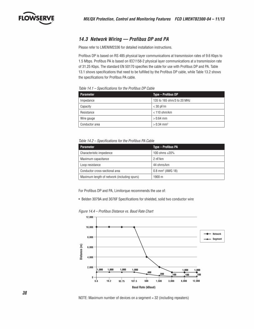
MX/QX Protection, Control and Monitoring Features FCD LMENTB2300-04 – 11/13
38
14.3 Network Wiring — Profibus DP and PAPlease refer to LMENIM2336 for detailed installation instructions.
Profibus DP is based on RS 485 physical layer communications at transmission rates of 9.6 Kbps to 1.5 Mbps. Profibus PA is based on IEC1158-2 physical layer communications at a transmission rate of 31.25 Kbps. The standard EN 50170 specifies the cable for use with Profibus DP and PA. Table 13.1 shows specifications that need to be fulfilled by the Profibus DP cable, while Table 13.2 shows the specifications for Profibus PA cable.
Table 14.1 – Specifications for the Profibus DP CableParameter Type – Profibus DP
Impedance 135 to 165 ohm/3 to 20 MHz
Capacity < 30 pF/m
Resistance < 110 ohm/km
Wire gauge > 0.64 mm
Conductor area > 0.34 mm2
Table 14.2 – Specifications for the Profibus PA CableParameter Type – Profibus PA
Characteristic impedence 100 ohms ±20%
Maximum capacitance 2 nF/km
Loop resistance 44 ohms/km
Conductor cross-sectional area 0.8 mm2 (AWG 18)
Maximum length of network (including spurs) 1900 m
For Profibus DP and PA, Limitorque recommends the use of:
• Belden 3079A and 3076F Specifications for shielded, solid two conductor wire
Figure 14.4 – Profibus Distance vs. Baud Rate Chart
NOTE: Maximum number of devices on a segment = 32 (including repeaters)
12,000
10,000
8,000
6,000
4,000
2,000
09.6 1,500 3,000 12,000
Dist
ance
(m)
Baud Rate (kBaud)
Network
Segment
19.2 93.75 187.5 500 6,000
1,000 1,000 1,000 1,000 1,000 1,000
100100200400100
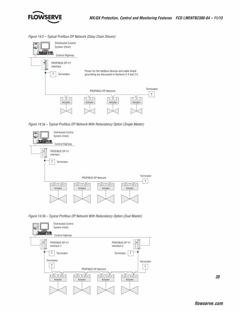
39
MX/QX Protection, Control and Monitoring Features FCD LMENTB2300-04 – 11/13
flowserve.com
Figure 14.5 – Typical Profibus DP Network (Daisy Chain Shown)
Actuator Actuator Actuator
PBPBPBPB
Actuator
PROFIBUS DP-V1Interface
Control Highway
Distributed ControlSystem (Host)
T Terminator
T
TerminatorPROFIBUS DP Network
Power for the fieldbus devices and cable shield grounding are discussed in Sections 2.4 and 2.5.
Figure 14.5a – Typical Profibus DP Network With Redundancy Option (Single Master)
PROFIBUS DP-V1Interface
Control Highway
Distributed ControlSystem (Host)
Terminator
PROFIBUS DP Network
Actuator
PBDP-A PBDP-B
Actuator
PBDP-A PBDP-B
Actuator
PBDP-A PBDP-B
Actuator
PBDP-A PBDP-B
T
Terminator
T
Figure 14.5b – Typical Profibus DP Network With Redundancy Option (Dual Master)
PROFIBUS DP-V1Interface-1
Control Highway
Distributed ControlSystem (Host)
Terminator
PROFIBUS DP Network
Actuator
PBDP-A PBDP-B
Actuator
PBDP-A PBDP-B
Actuator
PBDP-A PBDP-B
Actuator
PBDP-A PBDP-B
Terminator
T Terminator T
PROFIBUS DP-V1Interface-2
T
Terminator
T
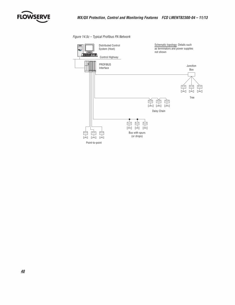
MX/QX Protection, Control and Monitoring Features FCD LMENTB2300-04 – 11/13
40
Figure 14.5c – Typical Profibus PA Network
PROFIBUSInterface
Control Highway
Distributed ControlSystem (Host)
JunctionBox
Tree
Daisy Chain
Bus with spurs(or drops)
Point-to-point
Schematic topology: Details suchas terminators and power suppliesnot shown
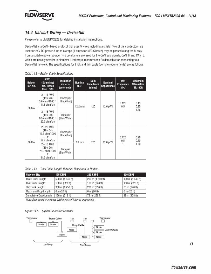
41
MX/QX Protection, Control and Monitoring Features FCD LMENTB2300-04 – 11/13
flowserve.com
14.4 Network Wiring — DeviceNetPlease refer to LMENIM2328 for detailed installation instructions.
DeviceNet is a CAN - based protocol that uses 5 wires including a shield. Two of the conductors are used for 24V DC power & up to 8 amps (4 amps for NEC Class 2) may be passed along the hi-way from a suitable power source. Two conductors are used for the CAN bus signals, CAN_H and CAN_L, which are usually smaller in diameter. Limitorque recommends Belden cable for connecting to a DeviceNet network. The specifications for thick and thin cable (per site requirements) are as follows:
Table 14.3 – Belden Cable Specifications
Belden Part No.
AWG (Stranding) dia. Inches Nom. DCR
Insulation material
(color code)
Nominal O.D.
Nom Impedance
(ohms)
Nominal Capacitance
Test Frequency
(MHz)
Maximum Attenuation
dB/100ft
3082A
2 – 15 AWG (19 x 28)
3.6 ohm/1000 ft 11.8 ohm/km
Power pair (Black/Red)
12.2 mm 120 12.0 pF/ft 0.125 0.5 1
0.13 0.25 1.36
2 – 18 AWG (19 x 30)
6.9 ohm/1000 ft 22.7 ohm/km
Data pair (Blue/White)
3084A
2 – 22 AWG (19 x 34)
17.5 ohm/1000 ft
57.4 ohm/km
Power pair (Black/Red)
7.2 mm 120 12.0 pF/ft
0.125 0.5 1
0.29 0.50 1.70 2 – 18 AWG
(19 x 36) 28.0 ohm/1000
ft 91.9 ohm/km
Data pair (Blue/White)
Table 14.4 – Total Cable Length Between Repeaters or Nodes:
Network Size 125 KBPS 250 KBPS 500 KBPS
Thick Trunk Length 500 m (1 640 ft) 250 m (1 640 ft) 100 m (1 640 ft)Thin Trunk Length 100 m (328 ft) 100 m (328 ft) 100 m (328 ft)Flat Trunk Length 380 m (1 250 ft) 200 m (656 ft) 75 m (246 ft)Maximum Drop Length 6 m (20 ft) 6 m (20 ft) 6 m (20 ft)Cumulative Drop Length 156 m (512 ft) 78 m (256 ft) 39 m (128 ft)Note: Each actuator includes 0.60 meters of internal drop length.
Figure 14.6 – Typical DeviceNet Network
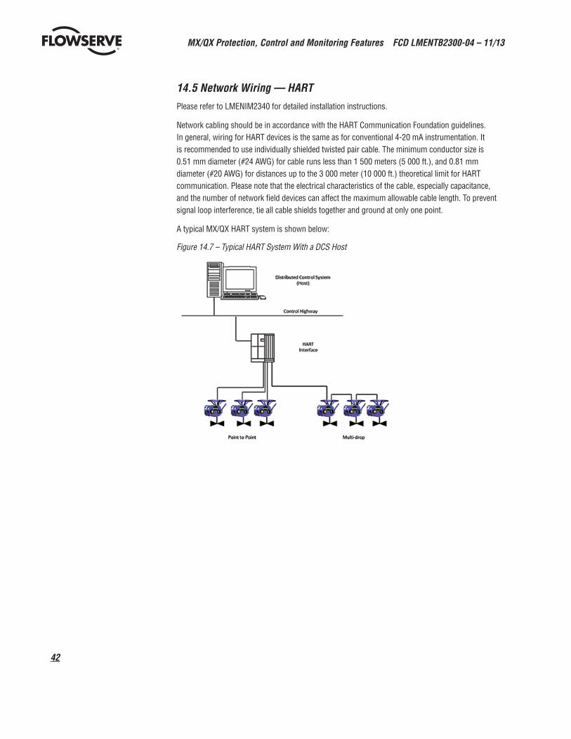
MX/QX Protection, Control and Monitoring Features FCD LMENTB2300-04 – 11/13
42
14.5 Network Wiring — HART Please refer to LMENIM2340 for detailed installation instructions.
Network cabling should be in accordance with the HART Communication Foundation guidelines. In general, wiring for HART devices is the same as for conventional 4-20 mA instrumentation. It is recommended to use individually shielded twisted pair cable. The minimum conductor size is 0.51 mm diameter (#24 AWG) for cable runs less than 1 500 meters (5 000 ft.), and 0.81 mm diameter (#20 AWG) for distances up to the 3 000 meter (10 000 ft.) theoretical limit for HART communication. Please note that the electrical characteristics of the cable, especially capacitance, and the number of network field devices can affect the maximum allowable cable length. To prevent signal loop interference, tie all cable shields together and ground at only one point.
A typical MX/QX HART system is shown below:
Figure 14.7 – Typical HART System With a DCS Host

43
MX/QX Protection, Control and Monitoring Features FCD LMENTB2300-04 – 11/13
flowserve.com
This page left blank intentionally
flowserve.com
Flowserve CorporationFlow Control
United StatesFlowserve Limitorque5114 Woodall Road P.O. Box 11318Lynchburg, VA 24506-1318Phone: 434-528-4400Facsimile: 434-845-9736
EnglandFlowserve LimitorqueEuro HouseAbex RoadNewburyBerkshire, RG14 5EYUnited KingdomPhone: 44-1-635-46999Facsimile: 44-1-635-36034
JapanLimitorque – Nippon Gear Co., Ltd.Asahi-Seimei Bldg. 4th Floor1-11-11 Kita-Saiwai, Nishi-KuYokohama-Shi, (220-0004)JapanPhone: 81-45-326-2065Facsimile: 81-45-320-5962
CanadaFlowserve Limitorque120 Vinyl CourtWoodbridge, Ontario L4L 4A3CanadaPhone: 905-856-4565Fax: 905-856-7905
SingaporeLimitorque Asia, Pte., Ltd.12, Tuas Avenue 20Singapore 638824Phone: 65-6868-4628Facsimile: 65-6862-4940
IndiaFlowserve Limitorque No. 10-12, THE OVAL, Third floor Venkatnarayana Road T. Nagar, Chennai 600 017 Phone: +91-44-2432-8755 & +91-44-2432-4801 Facsimile: +91-44-2432-8754
ChinaLimitorque Beijing PTE LTDRM A1/A222/F, East Area, Hanwei PlazaNo. 7 Guanghua RoadChaoyang DistrictBeijing 100004People’s Republic of ChinaPhone: 86-10-5921-0606Facsimile: 86-10-6561-2702
FCD LMENTB2300-04 (E) 11/13
To find your local Flowserve representative:
For more information about Flowserve Corporation, visit www.flowserve.com or www.limitorque.com, or call USA 1 800 225 6989.
Flowserve Corporation has established industry leadership in the design and manufacture of its products. When properly selected, this Flowserve product is designed to perform its intended function safely during its useful life. However, the purchaser or user of Flowserve products should be aware that Flowserve products might be used in numerous applications under a wide variety of industrial service conditions. Although Flowserve can (and often does) provide general guidelines, it cannot provide specific data and warnings for all possible applications. The purchaser/user must therefore assume the ultimate responsibility for the proper sizing and selection, installation, operation, and maintenance of Flowserve products. The purchaser/user should read and understand the Installation Operation Maintenance (IOM) instructions included with the product, and train its employees and contractors in the safe use of Flowserve products in connection with the specific application.
While the information and specifications contained in this literature are believed to be accurate, they are supplied for informative purposes only and should not be considered certified or as a guarantee of satisfactory results by reliance thereon. Nothing contained herein is to be construed as a warranty or guarantee, express or implied, regarding any matter with respect to this product. Because Flowserve is continually improving and upgrading its product design, the specifications, dimensions and information contained herein are subject to change without notice. Should any question arise concerning these provisions, the purchaser/user should contact Flowserve Corporation at any one of its worldwide operations or offices.
© 2011 Flowserve Corporation, Irving, Texas, USA. Flowserve is a registered trademark of Flowserve Corporation. Windows is a registered trademark of Microsoft Corporation in the United States and other countries. The Bluetooth word mark and logo are registered trademarks and are owned by the Bluetooth SIG, Inc.