limit state of serviceability in rcc
DESCRIPTION
Description of limit state of serviceability in the design of RCC structures.TRANSCRIPT

Prepared by Dr. Prashanth J. Design of RCC Structures 1
UNIT 3: FLEXURE AND SERVICEABILITY LIMIT STATES
3.1 GENERAL
In the previous chapter, the behaviour of reinforced concrete beams was explained, and
procedures given for the analysis of sections. It may be noted that the results of the analysis of a
given beam section is unique, being dictated solely by the conditions of equilibrium of forces and
compatibility of strains. On the basis of these computations, it is possible to decide whether or
not the beam is „safe‟ under known moments.
The design problem is somewhat the reverse of the analysis problem. The external loads (or load
effects), material properties and the skeletal dimensions of the beam are given, and it is required
to arrive at suitable cross-sectional dimensions and details of the reinforcing steel, which would
give adequate safety and serviceability. In designing for flexure, the distribution of bending
moments along the length of the beam must be known from structural analysis. For this, the
initial cross-sectional dimensions have to be assumed in order to estimate dead loads; this is also
required for the analysis of indeterminate structures (such as continuous beams). The adequacy
of the assumed dimensions should be verified and suitable changes made, if required.
NOTE: Unlike the analysis problem, the design problem does not have a unique solution because the flexural
strength of a section is dependent on its width and effective depth, and on the area of reinforcement; and there
are several combinations of these which would give the required strength. Different designers may come up with
different solutions, all of which may meet the desired requirements.
A complete design of a beam involves considerations of safety under the ultimate limit states in
flexure, shear, torsion and bond, as well as considerations of the serviceability limit states of
deflection, crack-width, durability etc.
Prior to taking up problems related to design in flexure, it is necessary to have first an
understanding of the requirements related to the placing of flexural reinforcement, control of
deflection, as well as other guidelines for the selection of member sizes. These are discussed in
the following sections.
3.2 REQUIREMENTS OF FLEXURAL REINFORCEMENT
3.2.1 Concrete Cover
Clear cover is the distance measured from the exposed concrete surface (without plaster and
other finishes) to the nearest surface of the reinforcing bar. The Code (Cl. 26.4.1) defines the
term nominal cover as “the design depth of concrete cover to all steel reinforcements, including
links”. This cover is required to protect the reinforcing bars from corrosion and fire, and also to
give the reinforcing bars sufficient embedment to enable them to be stressed without „slipping‟

Prepared by Dr. Prashanth J. Design of RCC Structures 2
(losing bond with the concrete). As mentioned earlier, the recent revision in the Code with its
emphasis on increased durability, has incorporated increased cover requirements, based on the
severity of the environmental exposure conditions.
The „nominal cover‟ to meet durability requirements, depending on exposure condition, are
summarized in Table 3.1. As corrosion of reinforcing bars is a common and serious occurrence,
it is advisable to specify liberal clear cover in general (particularly in excessively wet and humid
environments, and in coastal areas). It may be noted that in actual construction, the clear cover
obtained may be (and often is) less than the specified clear cover; however, this should be within
the tolerance allowed and appropriate allowance should be made for such errors in construction.
In this context, it is important to note the revised tolerance specified in IS 456 (2000), according
to which the maximum deviation in clear cover from the value specified by the designer are “+10
mm and –0 mm” (No reduction in clear cover is permitted; an increase in clear cover up to 10
mm above the specified nominal cover is allowed).
Table 3.1: Nominal cover requirements based on exposure conditions
The clause in the earlier version of the Code, limiting the maximum clear cover in any
construction to 75 mm, for some reason, has been eliminated in the revised code. The general
message underlying the revised recommendations in the code pertaining to clear cover seems to
be: “the more the cover, the more durable the concrete”. Unfortunately, the code does not also
convey the message that the provision of very large covers (100 mm or more) is undesirable, and
can be counter-productive, causing increased crack-widths, particularly in flexural members
(such as slabs and beams). Large crack-widths (greater than 0.3 mm) permit the ingress of
moisture and chemical attack to the concrete, resulting in possible corrosion to reinforcement and
deterioration of concrete. There is little use in providing increased cover to reinforcement, if that
cover is cracked, and the likelihood of cracking increases with increased cover. It is therefore
necessary to impose an upper limit to clear cover (usually 75 mm), and to enforce the checking
for the limit state of cracking when large covers are provided.
It may be noted that in the earlier version of the Code, the clear cover requirements were based
on the type of structural element (for example, 15 mm in slabs, 25 mm in beams, 40 mm in
columns, etc.). The clear cover specifications are now made applicable for all types of structural

Prepared by Dr. Prashanth J. Design of RCC Structures 3
elements. However, certain minimum clear cover requirements have been specified in Cl.
26.4.2.1 of the Code for columns (for longitudinal bars, 40 mm in general) and in Cl. 26.4.2.2 for
footings (50 mm in general).
In addition, the Code has introduced nominal cover requirements, based on fire resistance (in
terms of hours) required. They are described in Cl. 26.4.3 of the Code. In general, for a nominal
1 hour fire resistance, the nominal cover specified is 20 mm for beams and slabs, and 40 mm for
columns. Larger cover is required only if the structural element under consideration has to be
specially designed for fire resistance.
3.2.2 Spacing of Reinforcing Bars
The Code specifies minimum and maximum limits for the spacing between parallel reinforcing
bars in a layer. The minimum limits are necessary to ensure that the concrete can be placed easily
in between and around the bars during the placement of fresh concrete. The maximum limits are
specified for bars in tension for the purpose of controlling crack-widths and improving bond.
The minimum spacing limits can be met without difficulty in slabs in general, because of the
large widths available and the relatively low percentage of flexural reinforcement required.
However, in the case of beams, which have limited widths and are required to accommodate
relatively large areas of flexural reinforcement, the minimum spacing requirements can
sometimes govern the selection of the widths of the beams. If all the reinforcing bars cannot be
accommodated in a single layer with the necessary clearance between the bars and the clear
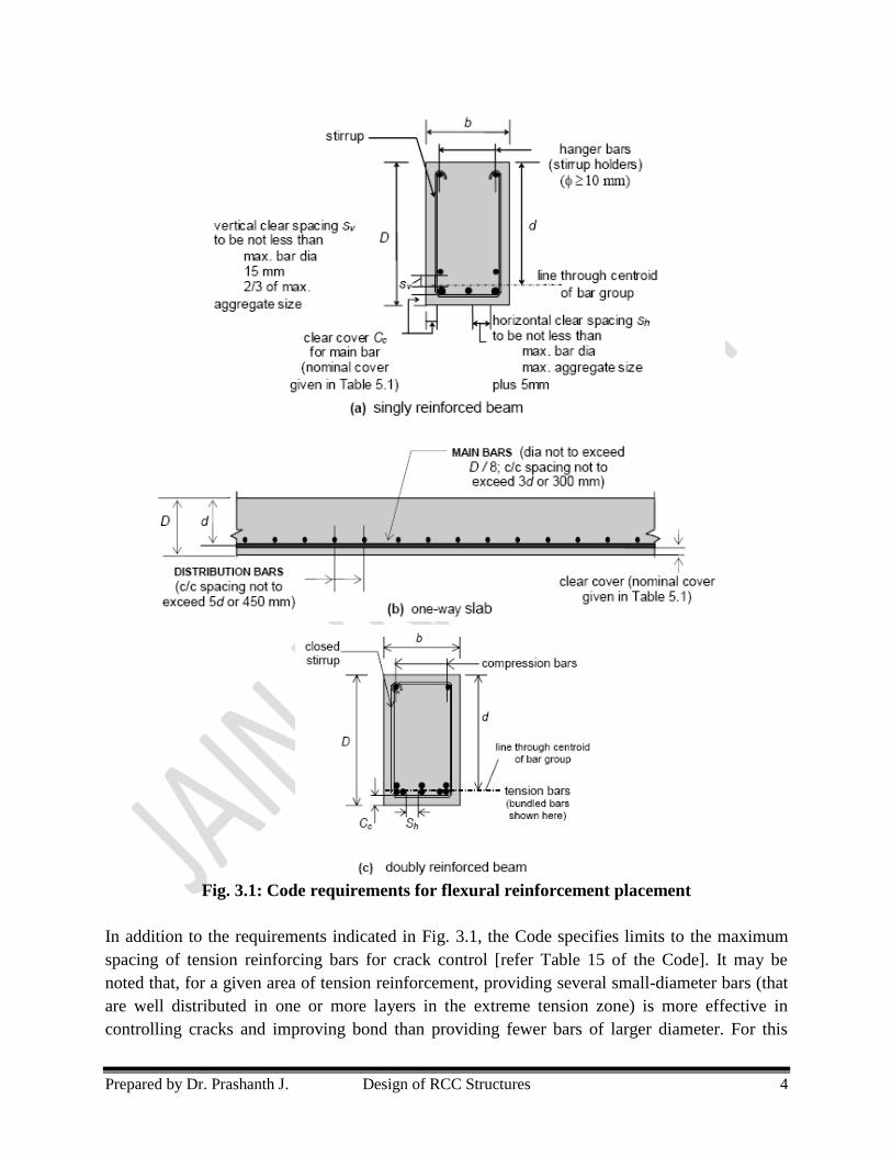
cover on the two sides [Fig. 3.1], the options are:
• to increase the beam width;
• to place the bars in two or more layers, properly separated [Fig. 3.1(a)]; and
• to bundle groups of parallel bars (two, three or four bars in each bundle) [Fig. 3.1(c)].
While fixing the overall size of the beam or the thickness of the slab, it is desirable to use
multiples of 5 mm for slabs and 50 mm (or 25 mm) for beams. This will be convenient in the
construction of the formwork. The requirements for placement of flexural reinforcement are
described in Cl. 26.3 of the Code. The salient features of these specifications are summarized in
Fig. 3.1. The requirements for singly reinforced beams, slabs and doubly reinforced beams are
depicted in parts (a), (b) and (c) respectively of Fig. 3.1.
Stirrups provided in beams serve as transverse shear reinforcement. In singly reinforced beams,
they may be provided as U-shaped stirrups, with two hanger bars at top [Fig. 3.1(a)]. However, it
is more common to provide fully closed rectangular stirrups [Fig. 3.1(c)], for both singly and
doubly reinforced sections; this is mandatory in the doubly reinforced sections for the effective
functioning of the compression steel. Stirrups required for resisting torsion must also be of the
closed form.
Prepared by Dr. Prashanth J. Design of RCC Structures 4
Fig. 3.1: Code requirements for flexural reinforcement placement
In addition to the requirements indicated in Fig. 3.1, the Code specifies limits to the maximum
spacing of tension reinforcing bars for crack control [refer Table 15 of the Code]. It may be
noted that, for a given area of tension reinforcement, providing several small-diameter bars (that
are well distributed in one or more layers in the extreme tension zone) is more effective in
controlling cracks and improving bond than providing fewer bars of larger diameter. For this

Prepared by Dr. Prashanth J. Design of RCC Structures 5
reason, the Code (Cl. 26.5.2.2 & 26.3.3b) limits the maximum diameter of reinforcing bars in
slabs to one-eighth of the total thickness of the slab, and the maximum spacing of such main bars
to 3d or 300 mm (whichever is less) [Fig. 3.1(b)]. However, it may be noted that when large
cover is provided, more stringent bar spacing may be required to achieve the desired crack
control.
The horizontal distance between two parallel main bars shall usually be not less than the greatest
of the following
i. Diameter of the bar if the diameters are equal
ii. The diameter of the larger bar if the diameters are unequal
iii. 5mm more than the nominal maximum size of coarse aggregate
Greater horizontal spacing than the minimum specified above should be provided wherever
possible. However when needle vibrators are used, the horizontal distance between bars of a
group may be reduced to two thirds the nominal maximum size of the coarse aggregate, provided
that sufficient space is left between groups of bars to enable the vibrator to be immersed.
Where there are 2 or more rows of bars, the bars shall be vertically in line and the minimum
vertical distance between the bars shall be of the greatest of the following
i. 15 mm
ii. Maximum size of aggregate
iii. Maximum size of bars
3.2.3 Minimum and Maximum Areas of Flexural Reinforcement
A minimum area of tension reinforcing steel is required in flexural members not only to resist
possible load effects, but also to control cracking in concrete due to shrinkage and temperature
variations.
Minimum Flexural Reinforcement in Beams
In the case of beams, the Code (Cl. 26.5.1.1) prescribes the following:
So,
In the case of flanged beams, the width of the web bw should be considered instead of b.
It can be shown that the (Ast)min given by the above equation results in an ultimate moment of
resistance that is approximately equal to the „cracking moment‟ of an identical plain concrete
section. Thus, the minimum reinforcement requirement ensures that a sudden failure is avoided
at M = Mcr.

Prepared by Dr. Prashanth J. Design of RCC Structures 6
Minimum Flexural Reinforcement in Slabs
As specified in Cl. 26.5.2, the minimum reinforcement (Ast)min in either direction in slabs is
given by
where Ag denotes the gross area of the section (b×D).
In the design of one-way slabs, this minimum reinforcement is also to be provided for the
secondary (or distributor) reinforcement along the direction perpendicular to the main
reinforcement, with the spacing of such bars not exceeding 5d or 450 mm (whichever is less)
[Fig. 3.1(b)]. It may be noted that in the case of slabs, sudden failure due to an overload is less
likely owing to better lateral distribution of the load effects. Hence, the minimum steel
requirements of slabs are based on considerations of shrinkage and temperature effects alone,
and not on strength. Accordingly, the specified value of (pt)min is somewhat smaller in the case of
slabs, compared to beams. However, for exposure conditions where crack control is of special
importance, reinforcement in excess of that given by the above equation should be provided.
Maximum Flexural Reinforcement in Beams
Providing excessive reinforcement in beams can result in congestion (particularly at beam-
column junctions), thereby adversely affecting the proper placement and compaction of concrete.
For this reason, the Code (Cl. 26.5.1) restricts the area of tension reinforcement (Ast) as well as
compression reinforcement (Asc) in beams to a maximum value of 0.04bD. If both Asc and Ast are
provided at their maximum limits, the total area (Asc + Ast) of steel would be equal to 8 percent
of the gross area of the beam section; this is rather excessive. It is recommended that such high
reinforcement areas should be generally avoided by suitable design measures. These include:
• increasing the beam size (especially depth);
• improving the grades of concrete and steel.
3.3 GUIDELINES FOR SELECTION OF MEMBER SIZES
As explained in Section 3.2, the selection of flexural member sizes (from a structural viewpoint)
is often dictated by serviceability criteria (need to control deflections and crack-widths) as well
as requirements related to the placement of reinforcement. However, there are other structural,
economic and architectural considerations that come into play in the design of reinforced
concrete beams.
3.3.1 General Guidelines for Beam Sizes
The design problem does not have a unique solution. Many choices of beam sizes are feasible in
any given design situation. In general, for the purpose of designing for flexure, it is economical

Prepared by Dr. Prashanth J. Design of RCC Structures 7
to opt for singly reinforced sections with moderate percentage tension reinforcement (pt ≈ 0.5 to
0.8 times pt,lim).
Given a choice between increasing either the width of a beam or its depth, it is always
advantageous to resort to increase in depth. This results not only in improved moment resisting
capacity, but also in improved flexural stiffness, and hence, less deflections, curvatures and
crack-widths. However, very deep beams are generally not desirable, as they result in a loss of
headroom or an overall increase in the building height. In general, the recommended ratio of
overall depth (D) to width (b) in rectangular beam sections is in the range of 1.5 to 2. It may be
higher (up to 3 or even more) for beams carrying very heavy loads. The width and depth of
beams are also governed by the shear force on the section. Often, architectural considerations
dictate the sizes of beams. If these are too restrictive, then the desired strength of the beam in
flexure can be provided by making it „doubly reinforced‟ and/or by providing high strength
concrete and steel. In the case of beam-supported slab systems which are cast integrally, the
beams can be advantageously modelled as „flanged beams‟.
In the case of building frames, the width of beams should, in general, be less than or equal to the
lateral dimension of the columns into which they frame. Beam widths of 200 mm, 250 mm and
300 mm are common in practice world-wide. Where the beam is required to support a masonry
wall, the width of the beam is often made such that its sides are flush with the finished surfaces
of the wall; thus, beam widths of 230 mm are also encountered in practice in India. In design
practice, the overall depths of beams are often fixed in relation to their spans. Span to overall
depth ratios of 10 to 16 are generally found to be economical in the case of simply supported and
continuous beams. However, in the case of cantilevers, lower ratios are adopted, and the beams
are generally tapered in depth along their lengths, for economy. Such traditional methods of
fixing the depth of beams are generally satisfactory from the viewpoint of deflection control for
the normal range of loads.
Note: From practical considerations, it is desirable to limit the number of different beam sizes in the same
structure to a few standard modular sizes, as this will greatly convenience the construction of formwork, and
permit reusability of forms.
3.3.2 General Guidelines for Slab Thicknesses
In the case of slabs, whose thicknesses are very small in comparison with the depths of beams,
the limiting span/depth (l/d) ratios will generally govern the proportioning. In practice, Fe 415
grade steel is most commonly used, and for such steel, a pt value of about 0.4 – 0.5 percent may
be assumed for preliminary proportioning. This gives a kt (Fig. 4 of IS:456-2000) value of about
1.25; accordingly, the required effective depth (for preliminary design) works out to about
span/25 for simply supported slabs and about span/32 for continuous slabs.

Prepared by Dr. Prashanth J. Design of RCC Structures 8
In order to determine the thickness of the slab, the clear cover (based on exposure, refer Table
3.1) plus half the bar diameter of the main reinforcement (usually along the shorter span) have to
be added to the effective depth, as indicated in Fig. 3.1(b). The calculated value of the thickness
should be rounded off to the nearest multiple of 5 mm or 10 mm.
3.4 REQUIREMENTS FOR DEFLECTION CONTROL
Excessive deflections in slabs and beams are generally undesirable as they cause psychological
discomfort to the occupants of the building, and also lead to excessive crack-widths and
subsequent loss of durability and ponding in roof slabs.
The selection of cross-sectional sizes of flexural members (thicknesses of slabs, in particular) is
often governed by the need to control deflections under service loads. For a given loading and
span, the deflection in a reinforced concrete beam or slab is inversely proportional to its flexural
rigidity. It is also dependent on factors related to long-term effects of creep and shrinkage. From
the point of view of design, it is the ratio of the maximum deflection to the span that is of
concern, and that needs to be limited. The Code (Cl. 23.2a) specifies a limit of span/250 to the
final deflection due to all loads (including long-term effects of temperature, creep and
shrinkage). Additional limits are also specified in Cl. 23.2(b) of the Code ⎯ to prevent damage to
partitions and finishes.
The explicit computation of maximum deflection can be rather laborious and made difficult by
the need to specify a number of parameters (such as creep coefficient and shrinkage strain as
well as actual service loads), which are not known with precision at the design stage. For
convenience in design, and as an alternative to the actual calculation of deflection, the Code
recommends certain span/effective depth (l/d) ratios which are expected to satisfy the
requirements of deflection control (Δ/l < 1/250). Nevertheless, explicit calculations of deflections
become necessary under the following situations:
• when the specified l/d limits cannot be satisfied;
• when the loading on the structure is abnormal; and
• when stringent deflection control is required.
3.4.1 Deflection Control by Limiting Span/Depth Ratios
For a rectangular beam, made of a linearly elastic material, the ratio of the maximum elastic
deflection to the span (Δ/l) will be a constant if the span /overall depth ratio (l/D) is kept
constant. This can be proved as follows for the case of a simply supported rectangular beam,
subjected to a uniformly distributed load „w‟ per unit length:

Prepared by Dr. Prashanth J. Design of RCC Structures 9
where σ is the bending stress at service loads, Z=bD
2/6 is the section modulus and I =bD
3/12 is
the moment of inertia.
Substituting the value of „w‟ and „I‟ in „‟, we get,
where, in the present case of a simply supported beam with uniformly distributed loading, the
„constant‟ works out to 5/24E.
The above equation is generalized, and holds good for all types of loading and boundary
conditions (with appropriately different constants). It is thus seen that, by limiting the l/D ratio,
deflection (in terms of Δl) can be controlled.
The above equation is not directly applicable in the case of reinforced concrete, because it is not
a linearly elastic material and the parameters σ, Z and E are not constants, being dependent on
such factors as the state of cracking, the percentage of reinforcement, as well as the long-term
effects of creep and shrinkage. The Code however adopts this concept, with suitable
approximations, and prescribes limiting l/d ratios for the purpose of deflection control.
3.4.2 Code Recommendations for Span/Effective Depth Ratios
The check for deflection is done through the following two 456:2000 (Refer clause 42.1)
1. Empirical Method
In this method, the deflection criteria of the member is said to be satisfied when the actual value
of span to depth ratio of the member is less than the permissible values. The IS code procedure
for calculating the permissible values are as given below:
a. Choosing the basic values of span to effective depth ratios (l/d) from the following,
depending on the type of beam
1. Cantilever = 8
2. Simply supported = 20
3. Continuous = 26
b. Modify the value of basic span to depth ratio to get the allowable span to depth ratio.
(l/d)Allowable = (l/d)Basic x kt x kc x kf

Prepared by Dr. Prashanth J. Design of RCC Structures 10
Where, kt = Modification factor obtained from Fig. 4 of IS 456:2000. It depends on the area of
tension reinforcement provided and the type of steel.
kc = Modification factor obtained from Fig. 5 of IS 456:2000. This depends on the area of
compression steel used.
kf = Reduction factor got from Fig. 6 of IS 456:2000.
Note: The basic values of l/d mentioned above are valid upto spans of 10m. The basic values are
multiplied by 10/span in meters except for cantilever. For cantilevers whose span exceeds 10 m the
theoretical method shall be used.
2. Theoretical method of checking deflection
The actual deflections of the members are calculated as per procedure given in annexure „C‟ of
IS 456:2000. This deflection value shall be limited to the following:
i. The final deflection due to all loads including the effects of temperature, creep and
shrinkage shall not exceed span/250.
ii. The deflection including the effects of temperature, creep and shrinkage occurring after
erection of partitions and the application of finishes shall not exceed span/350 or 20 mm
whichever is less.
3.5 CRACKING IN STRUCTURAL MEMBERS
Cracking of concrete occurs whenever the tensile stress developed is greater than the tensile
strength of concrete. This happens due to large values of the following:
1. Flexural tensile stress because of excessive bending under the applied load
2. Diagonal tension due to shear and torsion
3. Direct tensile stress under applied loads (for example hoop tension in a circular tank)
4. Lateral tensile strains accompanying high axis compressive strains due to Poisson‟s effect
(as in a compression test)
5. Settlement of supports
In addition to the above reasons, cracking also occurs because of
1. Restraint against volume changes due to shrinkage, temperature creep and chemical
effects.
2. Bond and anchorage failures.
Cracking spoils the aesthetics of the structure and also adversely affect the durability of the
structure. Presence of wide cracks exposes the reinforcement to the atmosphere due to which the
reinforcements get corroded causing the deterioration of concrete. In some cases, such as liquid
retaining structures and pressure vessels cracks affects the basic functional requirement itself
(such as water tightness in water tank).

Prepared by Dr. Prashanth J. Design of RCC Structures 11
3.5.1 Permissible crack width
The permissible crack width in structural concrete members depends on the type of structure and
the exposure conditions. The permissible values are prescribed in clause 35.3.2 of IS 456:2000
and are shown in table below
Table: Permissible values of crack width as per IS 456:2000
3.5.2 Control of cracking
The check for cracking in beams are done through the following 2 methods specified in IS
456:2000 clause 43.1
1. By empirical method:
In this method, the cracking is said to be in control if proper detailing (i.e. spacing) of
reinforcements as specified in clause 26.3.2 of IS 456:2000 is followed. These specifications
regarding the spacing have been already discussed under heading general specifications. In
addition, the following specifications shall also be considered
i. In the beams where the depth of the web exceeds 750 mm, side face reinforcement shall be
provided along the two faces. The total area of such reinforcement shall not be less than 0.1%
of the web area and shall be distributed equally on two faces at a spacing not exceeding 300
mm or web thickness whichever is less. (Refer clause 25.5.1.3 IS456:2000)
ii. The minimum tension reinforcement in beams to prevent failure in the tension zone by
cracking of concrete is given by the following
As = 0.85bd/fy (Refer clause 26.5.1.1 of IS 456:2000)
iii. Provide large number of smaller diameter bars rather than large diameter bars of the same
area. This will make the bars well distributed in the tension zone and will reduce the width of
the cracks.
2. By crack width computations:
In the case of special structures and in aggressive environmental conditions, it is preferred to
compute the width of cracks and compare them with the permissible crack width to ensure the
safety of the structure at the limit state of serviceability. The IS 456-2000 has specified an
analytical method for the estimation of surface crack width in Annexure-F which is based on the
British Code (BS: 8110) specifications where the surface crack width is less than the permissible
width, the crack control is said to be satisfied.

Problems:
1. Given the following data of a simply supported T beam, check the deflection criteria by
empirical method
Width of the beam (b) = 230 mm
Effective depth (d) = 425 mm
Effective span = 8.0 m
Area of tension steel required = 977.5 mm2
Area of tension steel provided = 1256 mm2
Area of compression steel provided = 628 mm2
Type of steel = Fe 415
Width of flange (bf) = 0.9 m
Width of web (bw) = 0.3 m
Solution:
Basic �� = 20 for simply supported beam from clause 23.2.1
Allowable �� = Basic
�� x Mt x Mc x Mf …………. (1)
�� = 1265�100230�425 = 1.30%
�� = 0.58�� × ��������������� ��!�����������"��# !�!
�� = 0.58 × 415 × 977.51256 = 187.3
From fig 4, for Pt = 1.3%, fs = 187.5 N/mm2
Mt = 1.1 ………. (a)
�& = 628 × 100230 × 425 = 0.65%
From fig 5, for Pc = 0.65%, Mc = 1.15 ………………(b)
From fig 6, for '(') =
*.+**.,* = 0.33, Mf = 0.80 ………(c)
Substituting a, b and c in equation (1)
We get allowable �� = 20 x 1.1 x 1.15 x 0.80 = 20.2

Actual �� =
-*../0 = 18.82 < allowable
��
Hence OK
2. A rectangular beam continuous over several supports has a width of 300 mm and overall
depth of 600 mm. The effective length of each of the spans of the beam is 12.0 m. The
effective cover is 25 mm. Area of compression steel provided is 942 mm2 and area of
tension steel provided is 1560 mm2. Adopting Fe 500 steel estimate the safety of the
beam for deflection control using the empirical method
Solution:
Allowable �� = Basic
�� x Mt x Mc x Mf …………. (1)
Basic �� = 26 as the beam is continuous
�� = 0.58�� × ��������������� ��!�����������"��# !�!
�� = 0.58 × 500 × 15601560 = 290
From fig 4, for fs = 290, Pt = 0.90, Mt = 0.9……….(a)
From fig 5, for Pc = 0.54%, Mc = 1.15 ……………….(b)
From fig 6, for '(') = 1.0, Mf = 1 ……………………(c)
The equation (1) shall be multiplied by 2*
�345 . � 2*2/ as the span of the beam is greater
than 10.0 m
Allowable �� =
2*2/ x 26 x 0.9 x 1.15 x 1 = 22.4
Actual �� =
2/*.060 = 20.86 < allowable
��
Hence deflection control is satisfied.

3. Find the effective depth based on the deflection criteria of a cantilever beam of 6m span.
Take fy = 415 N/mm2, Pt = 1%, Pc = 1%.
Solution:
Allowable �� = Basic
�� x Mt x Mc x Mf
Basic �� = 7 for cantilever beam
Assume 789:;<=>:;�7893:?@>�;� = 1.0
fs = 0.58 x 415 x 1= 240.7
From fig 4, for fs = 240, Pt = 1%, Mt = 1.0
From fig 5, for Pc = 1%, Mc = 1.25
From fig 6, for '(') = 1.0, Mf = 1
Allowable �� = 7 x 1.0 x 1.25 x 1.0 = 8.75
! = �-.60 =
A***-.60 = 685 mm
4. A simply supported beam of rectangular cross section 250mm wide and 450mm overall
depth is used over an effective span of 4.0m. The beam is reinforced with 3 bars of
20mm diameter Fe 415 HYSD bars at an effective depth of 400mm. Two anchor bars of
10mm diameter are provided. The self weight of the beam together with the dead load on
the beam is 4 kN/m. Service load acting on the beam is 10 kN/m. Using M20 grade
concrete, compute
a. Short term deflection
b. Long term deflection
Solution:
Data b = 250 mm, D = 450 mm, d = 400 mm, fy = 415 N/mm2
Ast = 3 x B.x 20
2 = 942 mm
2, l = 4.0 m, D.L = 4 kN/m, Service load = 10 kN/m,
Total load = 14 kN/m, fck = 20, Asc = 2 x B.x 10
2 = 158 mm
2
Es = 2.1 x 10⁵ , Ec = 5000 C�&D = 22360 N/mm
2
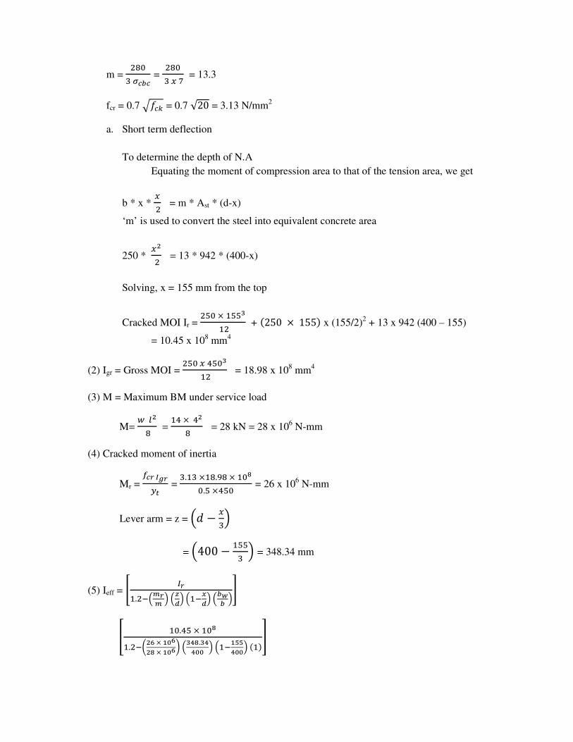
m = /-*
+EFGF = /-*
+H6= 13.3
fcr = 0.7 C�&D = 0.7 √20 = 3.13 N/mm2
a. Short term deflection
To determine the depth of N.A
Equating the moment of compression area to that of the tension area, we get
b * x * H/ = m * Ast * (d-x)
‘m’ is used to convert the steel into equivalent concrete area
250 * HJ/ = 13 * 942 * (400-x)
Solving, x = 155 mm from the top
Cracked MOI Ir = /0*×200K
2/ + L250 × 155M x (155/2)2 + 13 x 942 (400 – 155)
= 10.45 x 108 mm
4
(2) Igr = Gross MOI = /0*H.0*K
2/ = 18.98 x 108 mm
4
(3) M = Maximum BM under service load
M= N�J
- = 2.×.J
- = 28 kN = 28 x 106 N-mm
(4) Cracked moment of inertia
Mr = OFPQRP�9 =
+.2+×2-.,-×2*S*.0×.0* = 26 x 10
6 N-mm
Lever arm = z = T! − H+V
= T400 − 200+ V = 348.34 mm
(5) Ieff = W XP2./YTZPZ VT[\VT2Y]\VTG(G V^
_ 2*..0×2*S2./Y`Ja×bca
JS×bcadTKeS.Keecc VT2YbffeccVL2Mg

Ieff = 14.93 x 108 mm
4
Further Ir < Ieff < Igr
(6) Maximum short term deflection
ai(perm) = h(N�eiFXj)) =
0+-. 2.×L.***MJ
//+A*×2..,+×2*S = 1.39 mm
Kw = 0
+-. for SSB with UDL
b. Long term deflection
(1) Shrinkage deflection (acs):
acs = K3 ψcs L2
K3 = 0.125 for simply supported beam from Annexure C-3.1
ψcs = Shrinkage curvature = k. TlF8m V
n&� = Ultimate shrinkage strain of concrete (refer 6.2.4) = 0.0003
�� = 2**×,.//0*×.** = 0.942
�& = 2**×20-/0*×.** = 0.158
Pt - Pc = (0.942 – 0.158) = 0.784
This is greater than 0.25 and less than 1.0 Hence ok.
Therefore k. = 0.72 ×o9YoFCo9 = 0.72 ×*.,./Y*.20-√*.,./
K4 = 0.58
ψcs = *.0-×*.***+
.0* = 3.866 x 10⁻⁷
acs = K3 ψcs L2
= 0.125 x 3.866 x 10-7
x (4000)2
= 0.773 mm
(2) Creep deflection [acc(perm)]
Creep deflection acc(perm) = aicc(perm) – ai(perm)
Where, acc(perm) = creep deflection due to permanent loads

aicc(perm) = short term deflection + creep deflection
ai(perm) = short term deflection
aicc (perm) = kN ` N�KiFjXj))d
p&; = iFL2qrM = iFL2q2.AM
s = Creep coefficient = 1.6 for 28 days loading
aicc(perm) = 2.6 x short term deflection
= 2.6 x ai(perm)
= 2.6 x 1.39 = 3.614 mm
Creep deflection acc(perm) = 3.614 – 1.39 = 2.224 mm
Total long term deflection = shrinkage deflection + Creep deflection
= 0.773 + 2.224 = 3.013 mm
Total deflection = Short term deflection + Long term deflection
= 1.39 + 3.013 = 4.402 mm
5. A simply supported beam of rectangular section spanning over 6 m has a width of
300mm and overall depth of 600 mm. The beam is reinforced with 4 bars of 25 mm
diameter on the tension side at an effective depth of 550 mm spaced 50 mm centres. The
beam is subjected to a working load moment of 160 kN.m at the centre of the span
section. Using M-25 grade concrete and Fe-415 HYSD bars, check the beam for
serviceability limit state of cracking according to IS:456-2000 method. The beam is
protected and not exposed to aggressive environmental conditions.
a. Data:
b = 300 mm fck = 25 N/mm2
h = 600 mm fy = 415 N/mm2
d = 550 mm Es = 2 x 10⁵ N/mm
2
M = 160 kN.m spacing between bars s = 5 mm
Ast = 1963 mm2
cover = 50mm
For fck = 25 N/mm2, from table 21 IS 456
t&'& = 8.5u/ww/
w = /-*+EFGF
= 11

b. Neutral axis depth
Let x = depth of neutral axis
Then we have 0.5 b�/ = m Ast (d-x)
0.5 x 300�/ = 11 x 1963 (550-x)
Solving, x = 220 mm
c. Cracked moment of area (Ir):
Ir = (bx3/3) + m Ast r
2
Where r = (d-x) = (550-220) = 330 mm
Ir = T+**×//*K+ V +L11 × 1963 ×330/M
= 34.1 x 108 mm
4
d. Maximum width of cracks
Cover = Cmin = (50 - 12.5) = 37.5
acr = [(0.5 S)2 + C
2min]
1/2
= [(0.5 x 50)2 + 37.5
2]1/2
= 45
Crack width will be maximum at the soffit of the beam
Distance of the centroid of steel from neutral axis
= r = (d-x) = (50-220) = 330 mm
Therefore n2 = TO8i8V yzYH�YH{
Where, �� = w y|�XP { = 11 y2A*×2*a×++*
+..2×2*S { = 170 N/mm2
Therefore, n2 = T 26*/×2*fV yA**Y//*
00*Y//*{ = 9.78 x 10⁻⁴
n} = n2 − y'9LzYHMLzYHM+i878L�YHM {
n} = L9.78 × 10Y.M − y +**LA**Y//*MLA**Y//*M+×/×2*f×2,A+L00*Y//*M{
= 8.67 x 10⁻⁴

Maximum width of crack is expressed as:
~&: = W +���єZ2q/��FP�FZ����] �^
~&: = W+×.0×-.A6×2*�e2q/� ef�K�.facc�JJc� ^
= 0.113 mm< Permissible crack width of 0.3mm from clause 35.3.2
page 67. Hence ok.