light-weight radioisotope thermoelectricgenerator …/67531/metadc... · light-weight radioisotope...
TRANSCRIPT

LIGHT-WEIGHT RADIOISOTOPE THERMOELECTRICGENERATOR DESIGN'
Alfred Schock Fairchild Space & Electronics Co.. Germantown, Md. 20767
Abstract- Design concepts to reduce RTG weights are described. These concepts are m the area of the isotope heat source, the thermoelectr ic con\er ter , and the radia tor . Their effectiveness is demonstrated by means of an illustrative design for a 360-watt, plutonium-fueled generator with spritig loaded selenide elements . The generator, including necessary safety provisiot s for various abort modes, hjs an EOM specific po»pr of T to (i watt ' lb
it!
0 ^
1. INTRODUCTION
Recent application studies [1 ] for space nuclear power systems have again demonstrated the extreme importance of low weights, or high specific powers, in determining the applicability of nuclear power in space. Nuclear power systems with present weights are generally not competitive for missions which can use solar power, and even missions which cannot use solar power may require very low-weight nuclear systems to make them attractive enough to proceed. Although advanced nuclear power systems under current development are much more competitive, even these systems will have to be designed with attention to weight minimization,to compete with advanced systems using violet solar cells and Ni-H2 batteries, which may soon be available.
One of the advanced nuclear systems under current study is that of a thermoelectric generator (RTG) using selenide converter elements. This class of materials is under active development, and has demonstrated much higher performance potential and stability than those of currently used thermoelectric mater ia ls . [2]
In view of the great importance of achieving low weights which has-been demonstrated in our application studies, it was decided to investigate what weight r e duction can be achieved in a plutonium-fueled RTG designed for maximum specific power. This investigation led to certain novel design concepts, in three pr i mary areas: the converter (particularly the cold stack), the radiator str>icture, and the heat source. These concepts, which will be described, are not dependent on each other; i . e . , each could be used without the others. But maximum weight reduction is achieved by combining all three.
After describing and explaining these design concepts in qualitative te rms , the paper presents an illustrative design of a lightweight thermoelectric generator (LRTG) incorporating these features. Pertinent results of various analytical studies relating to normal operation and various abort modes are also presented. Although the design concepts described are general and could be applied to generators covering a wide range of power levels, for illustrative purposes the LRTG has been sized for an output power of approximately 400 watts 5.5 years after fueling, to facilitate comparison with other RTG designs produced in recent AEC studies.
* This work supported by AEC under contract AT(49-15)3063.
The various design changes described in this r e port yield an LRTG whose weight, allowing for some uncertainty about the required thickness of the Thornel impact shell, ranges from 71.7 to 80.6 lbs. With an EOM power output of 430 watts, this corresponds to a specific power range of 5.33 to 6.00 watts/lb. The latter value of specific power is 3-to-4 times as high as that of current-generation RTG's.
2. DESIGN CONCEPTS
2. 1 Cylindrical Configuration
One way of reducing the weight of the generator is to use most of its heat source surface for thermoelectric conversion, thus minimizing its inactive surface area. Reducing the inactive surface of the generator decreases the weight of the housing and the thermal insulation, and minimizes parasitic heat losses. This favors the use of prismatic or cylindrical heat sources, with their sides covered with thermocouples.
In a flat-sided generator, the load springs which press the thermocouples against the heat source produce considerable bending moments at the generator faces. These bending moments are minimized in a cylindrical generator, permitting the use of lightweight magnesium in spite of that material 's lower creep strength.
2. 2 Cold-Stack Assembly
In developing the LRTG design, it was felt that a major reduction in generator weight could be effected by a basic change from previously used cold-stack designs. In a thermoelectric generator with spring-loaded, unbonded elements, the cold stack has a dual role: mechanical and thermal. Mechanically, it provides high-pressure contact (150 to 300 psi) between cold shoe, thermocouple leg, hot shoe, and heat source, while compensating for dimensional changes due to thermal expansion and creep. Such contact is needed for thermal and electrical conductance. Thermally, the cold stack provides a heat flow path between the thermocouple cold strap and the generator case. The thermal conductance of that path must be high enough to avoid excessive temperature drops.
The cold stack must be designed for ease of as sembly and disassembly of the generator, without destruction of the converter or the heat source (electrical or nuclear). This disassembly requirement imposes a severe constraint on the generator design, and may necessitate inclusion of a rather heavy isolation can between the heat source and converter, to avoid
To be presented at the 9th Intersociety Energy Conversion Engineering Conference, August 1974.

DISCLAIMER
This report was prepared as an account of work sponsored by an agency of the United States Government. Neither the United States Government nor any agency Thereof, nor any of their employees, makes any warranty, express or implied, or assumes any legal liability or responsibility for the accuracy, completeness, or usefulness of any information, apparatus, product, or process disclosed, or represents that its use would not infringe privately owned rights. Reference herein to any specific commercial product, process, or service by trade name, trademark, manufacturer, or otherwise does not necessarily constitute or imply its endorsement, recommendation, or favoring by the United States Government or any agency thereof. The views and opinions of authors expressed herein do not necessarily state or reflect those of the United States Government or any agency thereof.

DISCLAIMER Portions of this document may be illegible in electronic image products. Images are produced from the best available original document.

creep deformation under the external spring load. Such creep deformation could prevent subsequent removal of the heat source. One of the goals of the LRTG cold-stack design was to achieve a major reduction of isolation can weight, without sacrifice of heat source removability.
Another goal was to eliminate the need for a cover gas in the converter. In the usual spring-loaded converter design, the spring-loaded pistons and the housing within which they slide must satisfy two conflicting goals: sufficient clearance between them to permit free movement of the piston; and good contact, to minimize thermal resistance. Thus, to prevent excessive temperature drops, the sliding contact area must be large to reduce the heat flux, and the gap must be filled with gas to improve heat transfer. The need for a large contact area requires a thick and relatively heavy housing (or heat sink bars), while the need for a cover gas introduces a potential failure mechanism, since loss of gas would result in overheating and excessive degradation of the thermoelements.
The above weight and unreliability penalties could be eliminated or greatly reduced if the springs could also serve as thermal conductors. However, this approach is not promising, because the material and geometrical requirements for a good spring are incompatible with those for a good conductor. A more promising approach is to separate the thermal and mechanical functions of the cold-stack assembly, by providing a separate, flexible, high-conductance heat path between the piston and the generator case. This eliminates the need for heat sink bars and for heat transfer across a sliding gap.
The LRTG cold-stack configuration for achieving these objectives is illustrated in both its loaded and unloaded positions in Figure 1. As shown, the waste heat from each thermocouple leg is delivered to the generator housing by sequential passage through a short aluminum piston, flexible multi-layer copper disks, an aluminum heat shunt, and a threaded loading cap. Both connections to the copper disks are brazed, to reduce thermal resistance. The central heat shunt is surrounded by a set of coaxial Belleville springs. These apply the desired pressure to the thermoelements, and simultaneously reduce the contact resistance at the interfaces between heat source, hot shoe, thermocouple leg, cold strap, piston, heat shunt, load cap and generator housing.
r r n 4. coL;-ST^cl< ASSEMBLY
NOBMH1.1.Y LOADED ^ ' ' ^ ^vtr^^^Z / CONDITION Coopta o scs ^ ^ - ^ ^ ^ CONDITION
As shown in Figure 1, the threaded cap is tightened with an Allen wrench, and is sealed to the generator housing by a Viton O-ring. Thus, the LRTG--like the MHW generator - - i s not perfectly sealed to vacuum. Before launch, during atmospheric operation, the converter is filled with a low-conductivity inert gas, to prevent the intrusion of air . The housing is connected to an inert gas reservoir , to maintain the internal pressure above one atmosphere in spite of leakage through the Viton-O-rings. After launch, the inert gas is vented to space, since selenide elements can operate stably in vacuum. (Helium from the heat-source-can may, if desired, be discharged directly, through a separate vent tube.)
As illustrated in Figure 1, the LRTG housing wall is quite thick (0.367 inch). As a result of that thickness and of the avoidance of flat-wall bending moments, the maximum hoop s t ress due to the prescribed spring loading is only 686 psi, well below the region of significant creep at the anticipated wall temperatures (/wl50 C). Because of this low stress level, the LRTG housing can be made of light-weight magnesium, in spite of its low creep strength.
2 . 3 Converter Assembly
The arrangement of the cold stack in relation to other converter components is illustrated in Figure 2, which presents an exploded view of the cold-stack components, and a view of the subassembly after fabrica-ition. It also shows the subassemblies loaded into the generator wall, both in their uncompressed and compressed conditions. Figure 2 also depicts the cold straps, and the thermocouple legs and hot shoes inserted into the cylindrical Min-K insulator shell.
FlEXlBit COPPER, PISTON m,|i^^
No bond between the thermocouple legs and the hot shoes is assumed. Interfacial contact is ensured by the spring load. The hot shoe shown acts as both a parallel and a series connector. Each molybdenum hot shoe is in contact with six legs, three n-type and three p-type. This arrangement reduces the number of parts handled during generator assembly, and permits closer spacing of parallel couples.

The assembly of the LRTG may be carried out in the following sequence: Firs t , the thermocouple legs and the hot shoes are placed into their positions in the Min-K insulator sleeve, and a cylindrical dummy heat source is inserted to retain the hot shoes during subsequent handling. Two options are available for the cold strap arrangement. One is to join two thermocouple legs to each copper cold strap with a bond that is at least strong enough to allow each thermocouple to be handled as a unit during generator assembly. The other option is to use a completely unbonded system. In that case, it seems preferable to reduce the number of pieces by using a single copper strap to series-connect groups of three parallel couples. These cold straps, each covering six thermocouple legs, could be held in place during assembly by means of retainting pins protruding into the Min-K insulator sleeve. This retention mechanism only needs to fulfill a temporary function, until the cold stack spring loads are applied. Special cold straps are used at the top and the bottom of the cylindrical converter assembly, to series-connect adjacent groups of parallel thermocouples.
After installation of the thermocouples in the Min-K sleeve, the cylindrical generator housing is slipped over the internal assembly, and the previously fabricated cold-stack subassemblies are loosely inserted into their mounting holes. Each retaining cap is threaded just far enough to engage the thread and make certain it moves freely, but not so far as to compress the Belleville springs. After this is done for the full generator, the cold-strap extensions from the first and last sets of three parallel thermocouples are connected to the appropriate pins of the generator te rminal. This terminal is sealed to the generator housing by means of Viton O-rings.
Next, the actual heat source, whether nuclear or electrical, is pushed up into the bottom of the generator assembly, thereby pushing the dummy heat source out the top without displacement of the hot shoes. Arrangements are then made to allow the heat source and generator housing to equilibrate near their normal operating temperatures. After that, the top and bottom covers are fastened to the generator housing, by bolts or Marman clamps. This locks the heat source in position. Viton O-rings are used to seal the covers to the housing. Finally, the partially inserted threaded cold-stack nuts are tightened, to compress the Belleville springs and apply the prescribed load to the thermoelectric legs. The tightening sequence must be carefully chosen to minimize unbalanced forces on the heat source. Two-stage compression may be desirable.
2.4 Radiators
Like earlier designs [3], the LRTG heat rejection system is based on the use of heatpipes, with copper walls and water working fluid, to minimize temperature gradients in the radiator. The heatpipe wicking arrangement, dimensions, weights, and assumed performance are based on units already built and tested by E)ynatherm Corporation [4]. To return the condensate to its evaporator section, each heatpipe employs a multiscreen wick in the form of a diametral slab, and has internal threads for circumferential flow of the condensate.
In the LRTG design, radial radiator panels come off the cylindrical housing. This configuration allows two options: wrapping the heatpipes around part of the generator wall; or confining the heatpipes to just the radiator panels, and depending en the conductance of the thick walls of the LRTG to deliver the heat from each cold stack to the nearest radiator panel.
The first of these options would undoubtedly r e sult in lower temperature drops along the generator wall; and may also result in lower weights, by permitting the use of fewer radiator panels and consequently less mutual blockage. The additional weight of the circumferential heatpipes would probably be less than the weight savings resulting from the improved radiator panel effectiveness.
While this type of arrangement has been successfully employed in RTGs, it is considerably more difficult to fabricate than radiators with straight heatpipes. Also, heatpipes with complicated bends and curves seem potentially less reliable, and the design would not lend itself well to testing before assembly. As will be shown, with the second option, each radiator panel can be fabricated and tested separately, before it is joined to the generator housing.
Because of its greater simplicity, fabricability, reliability, and testability, the second option was chosen for the LRTG. The omission of heatpipes around the generator housing is practical only because of the thick walls in this design. Even then, it imposes a lower limit on the number of radiator panels, to avoid excessive circumferential temperature drops.
The second, and more important, feature of the LRTG heat rejection system relates to the structural design of the radiator panels. The panel must be strong enough, particularly near its base where it joins the cylindrical housing, to withstand random forces due to shock, vibration, and acoustic inputs during launch. The acoustic forces present a particularly severe design problem for big, light-weight s tructures. In a large, cantilevered radiator panel, the weight of s t ructural reinforcements can exceed the weight of the panel 's thermal components. Stiffening ribs, which have been used in previous generators, can become prohibitively heavy for long panels.
To avoid excessive weights, a different reinforcement scheme is needed for the long radiator panels we wish to consider for the LRTG design. The most weight-effective way to stiffen a panel is to concentrate most of its mass in its outer skins, with only an extremely light-weight structure between the skins to resist the shear forces. This is the principle of honeycomb panels, which have been extensively employed in spacecraft because of their efficiency.
Fairchild's ATS-F spacecraft makes extensive use of honeycomb equipment support panels with embedded heatpipes for thermal control. While these use low-temperature aluminum-ammonia heatpipes, there is no inherent reason why the same type of panel could not be built with copper-water heatpipes for RTG radiators .
3

The proposed LRTG panel design is illustrated in Figure 3. After fabrication, processing, and performance verification of the copper-water heatpipes, they and the intervening honeycomb core strips would be sandwiched between the panel skins, and the whole structure bonded simultaneously. The bonding process can employ a low-temperature braze alloy; or, because of the low operating temperature, a high-conductance adhesive can be used.
e&=IMfS4G P I N AT~AC"NG S-JB
M(y>j£Ycow6 EDCit C14ANMEL
FIGURE ?.•
RADIMOR PMvlEL STRUCTURE
The method of joining the radiator panels to the generator housing is also illustrated in Figure 3. Each panel is closed off with a deep U-shaped channel along its inner edge. After fabrication, the panels can again be thermally tested, to confirm that none of the heatpipes have been damaged. Structural and bond integrity tests can also be performed at this t ime. After these, the panels are joined to the cylindrical housing by mating the previously mentioned channels to the longitudinal ribs protruding from the generator wall. Note that each heatpipe projects beyond the panel's inner edge, the projecting ends fitting into blind holes in the generator case. The final joint is both mechanical (bolted) and thermal(brazed). Heat flows to the heatpipe evaporator section either directly from the cylindrical case, or indirectly through the protruding ribs and channels.
As will be shown in the illustrative design in Section 3, this radiator panel configuration can result in adequate strength and reasonable weights, even for very long panels.
2. 5 Heat Source The converter and radiator designs described
above could be advantageously used in conjunction with a number of different heat source designs, such as SNAP-19 [3], MHW [5] , or ERTG [ 7 ] . However, none of these provides a high enough surface heat flux to take full advantage of the high power daisity achievable with selenide thermoelements. Ideally, the heat source
o
should deliver over two watts(t) per cm"̂ of power-generating surface. Such a high value is difficult to approach with a plutonium-fueled heat source meeting all safety requirements.
One of the most severe problems in heat source design is to ensure survival of impact on granite,without fuel re lease. There are, in general, two distinct approaches for achieving this. The first is to strive for a low impact velocity, either by designing a single heat source with a low ballistic coefficient, or by subdividing it into small modules with high area-to-weight rat ios. The modular approach is only valid if disasem-bly of the heat source prior to final descent is assured for all possible abort modes. The second approach is to accept the high impact velocity of a compact integral-reentry heat source, and to prevent impact failure by surrounding the clad fuel capsules with sufficient thickness of a crushable protective shell to absorb most of the impact energy.
The use of the first approach in the LRTG design is possible but not ideal. Nonmodular sources with low ballistic coefficients tend to be heavy and to be incompatible with the more desirable converter configurations . Modular heat sources are better in these r e s pects, but the provision of individual reentry and/or impact protection for each module tends to result in a surface heat flux too low to match the optimum selenide converter.
To increase the surface heat flux, the LRTG heat source design is based on the second approach, which is the one used in the MHW generator [5]. There, each spherical fuel capsule is surrounded by a concentric shell made from Thornel fibers and graphitized im-pregnant. During impact on granite, the impacted material in the protective shell is crushed. This process, as well as the friction and shear during the subsequent hydrodynamic motion of the crushed fibers, apparently absorbs enough impact energy to permit survival of the iridium capsule. Tests on the MHW program have demonstrated that under the right conditions the capsules can survive impacts at high-velocity (e.g. 280 ft/sec).
The LRTG heat source design concept res ts on the basic conclusion that impact survival of the fuel capsule can be achieved by surrounding them with thick enough impact absorption shells. Based on that, the following simple configuration was postulated for a compact LRTG heat source:
The Pu02 fuel is contained in cylindrical capsules with ellipsoidal heads, with typical diameters of about two inches. Lower-power generators, e .g . , up to 150 w(e), would contain a single fuel capsule. High-power generators would contain a few such capsules, with the number chosen to keep the capsule's length-to-diameter ratio at not more than three or four.
4

The fuel capsules are embedded in a single, thick Thornel shell, which acts as both impact absorber and aeroshell. The cylindrical Thornel shell is in turn enclosed in molybdenum cladding, which provides shrapnel protection and can act as a gas enclosure to keep the generated helium out of the converter. As in the MHW generator, the heat source clad is vented via a suitable gas management system.
As shown in Section 3 .1 , the above configuration yields a heat source design with a high surface heat flux.
3. ILLUSTRATIVE DESIGN
To help illustrate and evaluate the various concepts discussed in Section 2, they have been incorporated into a design of a specific generator to produce approximately 400 watts (EOM, i . e . 5.5 years after fueling). Sections 3 .1 ,3 .2 , and 3.3 present detailed descriptions of the heat source, converter, and radiator, interwoven with a discussion of design rationale and pertinent analytical resul ts . The overall generator characteristics are summarized in Section 3.4.
3. 1 Heat Source
The illustrative LRTG heat source design is depicted in Figure 4. As shown, the heat source comprises three fuel capsules, each containing a fuel element of 2-inch diameter, 6.06-inch cylindrical length, and 0. 50-inch long ellipsoidal ends, giving a fuel volume of 347 cc per capsule.
LRTG HEAT SouKCE
1 ^ p
DtTfcil. tk
ir ' "^ ,,
( V
^•
K i j :
2 4 i 8 — —
( \ I / 1— 2-i,
'
i
Assuming a fuel density of 9. 17 gm/cc, which is 80% of the theoretical value, each capsule contains 3180 gm or 7.00 lbs of PUO2. The assumed isotopic purity of 80% Pu-238 gives a BOL thermal power of 0.40 w/gm Pu02, or 1272 w/capsule. Thus, the heat source produces 3815 watts(t) at the time of fueling, and 3651 watts(t) at the end of 5. 5 years .
The capsule walls were assumed to be iridium, although results presented later indicate that the use of platinum or platinum alloys may be possible, and indeed desirable. The iridium fuel capsules have a wall thickness of 0.020 inch and each weighs 0.952 lbs, giving a total of 23. 9 lbs for the three fueled capsules.
The most arbitrary part of the LRTG heat source design is the thickness of the Thornel shell. The major disadvantage of using the "impact absorption" approach is that there is presently no analytical technique with demonstrated ability to compute the shell thickness required for impact survival.
The present design practice is purely pragmatic. In essence, the shell thickness needed to survive impact at the predicted terminal velocity, must be determined by a series of air gun or sled tests , which is clearly an expensive and time-consuming process. Fortunately, enough experience has been gained on MHW tests to at least give reasonable confidence that thoria of appropriate density can be used to simulate the action of the Pu02 fuel. Thus, the more expensive fueled tests need only be run for final confirmation.
In the absence of adequate analytical techniques, the Thornel shell thickness can only be based on qualitative engineering judgment. Only a test program can determine what thickness will provide impact survival after reentry ablation (typically 0. 1 to 0.2 inch).
Figure 5 illustrates LRTG heat source designs with Thornel thicknesses of 1.0 inch and 1.5 inch, together with a comparative view of the MHW fuel sphere assembly, drawn to the same scale. In the LRTG illustrative design, the illustrations and safety analyses were arbitrarily based on a one-inch Thornel thickness around the two-inch diameter fuel capsules. However, at the end of the report. Figures 25 and 26 present sensitivity curves showing the dependence of generator weight and specific power on Thornel thickness, over the range from 1. 0 to 1.5 inch. This range is expected to bracket the required thickness, subject to experimental confirmation.
100" ^SSUM6D THORNEL THICKNBS, C0MPW2IS0M WITU MHVJ DESIGN
5

In the illustrative design, the one-inch thick Thornel shell weighs 11.1 lbs, and the 0.030-inch thick molybdenum anti-shrapnel shell an additional 3.8 lbs. This gives a total heat source weight of 38.8 lbs . , excluding the vent system. The heat source with either 1 inch or 1, 5 inch of Thornel has a terminal velocity at sea level of 88 m/sec (287 ft/sec), which is about 10% higher than the corresponding value for the MHW heat source.
Assuming an 800 C heat source surface temperature, helium-filled 0. 010-inch radiation gaps, an i r i dium emissivity of 0. 19, and using temperature-dependent and anisotropic thermal conductivities for the Thornel and the fuel, we compute normal (BOL) operating temperatures of lOOQOC at the inner surface of the Thornel, 1040OC at the iridium capsule, and 1351°C at the fuel centerline.
A number of abort conditions and their effects on the heat source described above were analyzed. With regard to reentry, two cases of orbital decay were examined, since this produces the highest capsule temperatures . The analysis assumed reentry from a 400, 000 ft. altitude, at an initial velocity of 25, 600 ft/sec and flight path angle of minus 0. 1 degree. The computations employed the HAC code for the aerodynamic and heating analysis and the TAP-4 program for the subsequent transient thermal analysis.
The first case analyzed was that of spinning r e entry. The computed results are presented in Figure 6, which displays the reentry temperature histories of the fuel centerline, the fuel capsule wall, and the Thornel shell 's inner and outer surfaces. Note that the LRTG fuel capsule wall reaches a maximum temperature of only 1610°C (2930°F). which is well below the 2215°C melting point of the iridium-carbon eutectic; and that the Thornel surface temperature never exceeds 2080°C (3780°F), which is far below the point where any significant graphite sublimation would take place.
The second reentry problem analyzed was the "side-on stable" case, which produces the highest thermal s t ress during orbital decay reentry. The results of that analysis are displayed in Figures 7 and 8. Figure 7.shows the same temperature histories as did Figure 6 for the spinning case. For the heat source surface and capsule wall, temperature histories are shown for both the stagnation line (0°) and the opposite (180°) location. As can be seen, the maximum capsule temper^ ature of 1680'-'C (3060°F) is somewhat higher than in the spinning case, though still considerably below the melting points of the Ir-C eutectic (2215 C) and of platinum (1769 C). The maximum heat source surface •temperature at the stagnation line is 2530°C (4590'3F). While considerably higher than in the s pinning case, this is still below the level at which appreciable graphite sublimation takes place. The instantaneous temperature distribution at about the time of maximum thermal s t ress (t = 5 min) is depicted in Figure 8.
OEBITAL DtC(kY RE ENTRY SiDt -OM STABLE
I f C M P
fUEU t
MoR>«L
•C -F
soao-
2SOO
FI6URE: C O R B H i L DECAY OEtMTIi-T
S I D E - O N SPlNKJiNCi
2 4 4
M I N U T E S
•W CUP
4 5 0 o ' F M STAQ^4A^lOM LINE
6

Another safety problem analyzed was that of a ten-minute heat source immersion in a 2343°C (4250°F) solid-fuel fire. The results of that analysis are depicted in Figure 9, which shows a curve of LRTG fuel capsule wall temperature, together with corresponding curves for the MHW [8] and PAD [9] designs. For the MHW case, two curves are shown: one for the bare fuel sphere assembly, and one for the FSA within the heat source assembly.
P I G 9 tllFECT OP TEM-M1NU1E SOLD-cu£u F»at @42eo*p
o 2 4 i e io
» / I N J T E S
Figure 9 shows that, for the postulated fire conditions, the LRTG capsule wall reaches the melting point of the iridium-carbon eutectic in seven minutes, compared to two minutes for the case of the PAD and of the bare MHW-FSA. However, recent test results suggest that the above fire model may be too conservative. An object landing on top of a burning solid-fuel block may, because of vapors leaving the fuel block surface, see an effective mean temperature that is appreciably lower than the maximum flame tempers-ture, perhaps by hundreds of degrees. This conclusion is based on the nonmelting of iridium in contact with carbon during solid-fire tes ts .
With regard to the proximity case, there is some question whether there is any real possibility of the fuel breaking into two blocks large enough to burn for more than five minutes. In any case, even if an object did land between two such blocks and did see an initial radiation temperature of 2343°C (4250°F), the effective fire temperature would diminish rapidly, due to r eces sion of the burning fuel blocks. For example, in the solid-fire model used in the MHW safety analysis, the effective radiation temperature drops from its initial value of 4250*^F to approximately 3500°F in two minutes, 3200OF in three minutes, and 2300°F in ten minutes. Applying the same model to the LRTG heat source analysis, we obtained the temperature histories shown in Figure 10, indicating a maximum capsule wall temperature of only 1580°C (2880°F), well below melting points of the Ir-C eutectic (2215°C) and platinum (17680C).
As noted, the peak fuel capsule wall temperatures remained below the melting point of platinum for all the accident modes investigated, except for the ten-minute 4250°F fire, which may be too conservative. If this is confirmed by further investigation, it suggests the use
of platinum or platinum alloy capsules in place of i r i dium, if compatibility between the fuel and graphite can be demonstrated. Platinum alloys would be cheaper, much easier to fabricate, and more resistant to high-temperature post-impact oxidation.
PIGUCE \0'. S O L I D P U E L Pit tE
DiMiNISWINa - TEK^PERATuftE h^oOEL.
•C ' F
3. 2 Converter Description
The LRTG contains 540 thermocouples and their 1080 legs are arranged in 36 rings of 30 legs each. The couples are electrically connected in a 180 x 3 se r ies -parallel network, to yield an output of 24.6 volts. This output could be raised to 36.9 volts by connecting the couples in a 270 x 2 network.
The 540 gadolinium-selenide n-legs have a 0.287-inch diameter and 0.3-inch length, and weigh 2. 56 lbs. The 540 copper-selenide p-legs have a 0.251-inch diameter and 0.3-inch length, and weigh 1.95 lbs. The 180 molybdenum hot shoes are 0.040 inch thick and weigh 1.45 lbs, and the 180 copper cold straps are 0.012 inch thick and weigh 0.62 lb. The Min-K thermal insulation has a weight of 1.05 lbs for the 0.32-inch thick perforated cylindrical sleeve (4.8-inch O.D. x 24.7-inch length), and 0. 66 lb for the two 1. 5-inch thick end disks.
The 1080 cold-stack assemblies, including pistons, springs, heat shunts, O-rings, and screw caps, have a total weight of 3.42 lbs. The cylindrical part of the geneifator housing has a 5. 7-inch outer diameter, 29. 0-inch length, and 1080 holes of 0.3-inch diameter. It has a wall thickness of 0. 37 inch over its 22. 0-inch power-producing length, and 0.08 inch beyond. Made of magnesium-thorium alloy, its weight is 8.2 lbs, including flanges and r ibs . The end covers and Marman-type closures of the generator weigh 1.2 lbs, for a total housing weight of 9.4 lbs.
3. 3 Radiator
The basic structural and thermal design concepts used in.the radiator were described in Section 2.4. In applying these concepts to a specific generator, one of the first questions to be resolved concerns the number of radiator panels attached to the generator housing. The fewer the panels, the less they block each other's view of space. With just two panels, there is no blockage at all.
On the other hand, the fewer the number of panels, the wider their angular spacing, which forces the heat from the cold stacks to traverse a longer distance
7
around the generator. This is no problem when the heatpipes are wrapped around the generator housing as in the HPG unit. But to avoid having to form and bond bent heatpipes, no circumferential sections were used in the LRTG design illustrated here . Wide angular spacings between panels can therefore lead to excessive temperature drops between cold junctions and radiators .
In addition, when the number of panels is decreased, their root-to-tip length must increase in order to reject the same total heat at a given radiator temperature. This increased length may ultimately be limited by the spacecraft envelope diameter, and may require thicker and therefore heavier honeycomb skins to resist the increased bending moments.
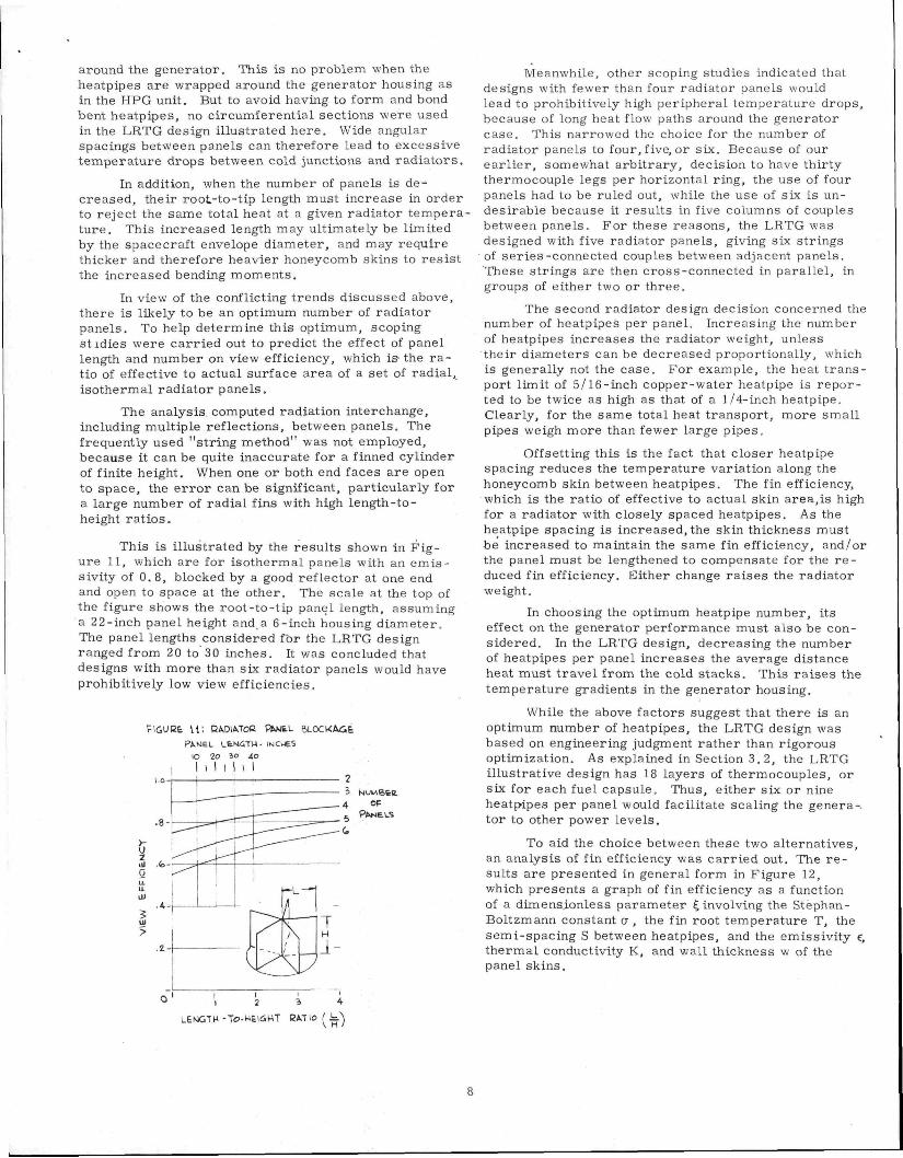
In view of the conflicting trends discussed above, there is likely to be an optimum number of radiator panels. To help determine this optimum, scoping St idles were carried out to predict the effect of panel length and number on view efficiency, which is the r a tio of effective to actual surface area of a set of radial, isothermal radiator panels.
The analysis computed radiation interchange, including multiple reflections, between panels. The frequently used "string method" was not employed, because it can be quite inaccurate for a finned cylinder of finite height. When one or both end faces are open to space, the e r ro r can be significant, particularly for a large number of radial fins with high length-to-height rat ios.
This is illustrated by the results shown in Figure 11, which are for isothermal panels with an emissivity of 0.8, blocked by a good reflector at one end and open to space at the other. The scale at the top of the figure shows the root-to-tip panel length, assuming a 22-inch panel height and a 6-inch housing diameter. The panel lengths considered for the LRTG design ranged from 20 to 30 inches. It was concluded that designs with more than six radiator panels would have prohibitively low view efficiencies.
IGUEt 1 1 ; RADIATOR PWJtL BLOCkACE
PAWEL U t N G T M - INCHES
lO 2o io 4o
, I I I I I I I 2 i Nui.<Sttt.
. 4 OF P A N E L S
2 ul 0
Meanwhile, other scoping studies indicated that designs with fewer than four radiator panels would lead to prohibitively high peripheral temperature drops, because of long heat flow paths around the generator case. This narrowed the choice for the number of radiator panels to four, five, or six. Because of our earl ier , somewhat arbitrary, decision to have thirty thermocouple legs per horizontal ring, the use of four panels had to be ruled out, while the use of six is undesirable because it results in five columns of couples between panels. For these reasons, the LRTG was designed with five radiator panels, giving six strings of series-connected couples between adjacent panels. These strings are then cross-connected in parallel, in groups of either two or three.
The second radiator design decision concerned the number of heatpipes per panel. Increasing the number of heatpipes increases the radiator weight, unless their diameters can be decreased proportionally, which is generally not the case. For example, the heat t ransport limit of 5/16-inch copper-water heatpipe is reported to be twice as high as that of a 1/4-inch heatpipe. Clearly, for the same total heat transport, more small pipes weigh more than fewer large pipes.
Offsetting this is the fact that closer heatpipe spacing reduces the temperature variation along the honeycomb skin between heatpipes. The fin efficiency, which is the ratio of effective to actual skin area,is high for a radiator with closely spaced heatpipes. As the heatpipe spacing is increased,the skin thickness must be increased to maintain the same fin efficiency, and/or the panel must be lengthened to compensate for the r e duced fin efficiency. Either change raises the radiator weight.
In choosing the optimum heatpipe number, its effect on the generator performance must also be considered. In the LRTG design, decreasing the number of heatpipes per panel increases the average distance heat must travel from the cold stacks. This raises the temperature gradients in the generator housing.
While the above factors suggest that there is an optimum number of heatpipes, the LRTG design was based on engineering judgment rather than rigorous optimization. As explained in Section 3.2, the LRTG illustrative design has 18 layers of thermocouples, or six for each fuel capsule. Thus, either six or nine heatpipes per panel would facilitate scaling the genera-, tor to other power levels.
To aid the choice between these two alternatives, an analysis of fin efficiency was carried out. The r e sults are presented in general form in Figure 12, which presents a graph of fin efficiency as a function of a dimens.ionless parameter 4 involving the Stephan-Boltzmann constant a , the fin root temperature T, the semi-spacing S between heatpipes, and the emissivity c, thermal conductivity K, and wall thickness w of the panel skins.
o ; 2 J 4
LEMGTH-To-Mtl<SHT RATIO ^ .k " )
8

FIGUBE 12
CEhJEEAL SOLUTION FOR RADlATIMG FINS
Z
u U-Ll-O l
z
o 2 4. C (S l o
5 5 (oeT ' s7KO^
The effect of skin thickness and heatpipe spacing is illustrated more clearly in Figure 13. The curves shown are based on an emissivity of 0. 8, a fin root temperature of 160°C, the thermal conductivity of magnesium or beryllium, and heatpipe spacings of 2.2 and 3.3 inches, respectively, corresponding to six and nine heatpipes per panel.
F I G u R t I 3 '
T H E R M A L E F P t C T OF SUIivl TWCk-NESS
AMD HEAT PIPE SPACIMQ
>-o 2 ul
. 2 -
HEAT PIPES PER P A K E L
O OOS OIO OI5 oZO
SK IN THICk.NE'SS - INCHES
As shown, heatpipe spacing has a pronounced effect on fin efficiency only for very thin panel skins, which may in any case be impractical from a fabrication standpoint. It was therefore decided to specify a minimum skin thickness of 0.010 inch. Since for thicknesses above that value reasonably high fin efficiencies can be achieved with only six heatpipes per panel, this was the design choice for the LRTG.
The final design decisions concern the interrelated questions of panel length and skin thickness. Optimization of these parameters requires the interplay of structural analysis, thermal analysis, and electrical analysis.
Addressing ourselves first to the structural question, a preliminary'survey indicated that the critical loading on the large, light-weight panels is that r e sulting from acoustic noise.
The acoustic response analysis assumed panels of 22-inch length, 20-inch height, and 0. 015-inch thick magnesium skins bonded to a 0.220-inch aluminum honeycomb core, for a total panel thickness of 0.25-inch. A 3. 3-inch center-to-center spacing between the copper heatpipes was assumed, and their strength contribution was neglected. Using an elastic modulus of 6 .5x l0"ps i , we coinputed a natural frequency of 19 Hz, and a cr i t i cal frequency of 183 Hz at 7 0 0 F and sea level.
The acoustic response analysis was based on the noise spectrum of the Atlas-Centaur vehicle, which is similar in severity to the Txtan-3C, and more severe than other Atlas launch vehicles. The design qualification input noise spectrum was obtained from S-320-6-1 (GSFC), and is depicted in Figure 14. The computed natural and critical frequencies are also s hown.
Figure 14
I «
1 155
s
" 130
^ £ i m S
m
ATLAS CENTAUR ACOUSTIC NOISE INTERIOR OF SHROUD
CRITICAL
FREQUENCY 1
•
1 1
NATURAL FREQUENCY
i' ' 1
1 ,
1 1
ni iu
1
1
. i l l
1
1
1 1 1
1
1
'
1
Ji
1, ii
1
h
"
1 \
' -̂ r t •"
1 11 02
10 000
Since the panel's critical frequencies are within the range of the acoustic energy spectrum, simple Mass-Law analysis could not be used. Instead Franken's method was employed. This method essentially adds an approximate amplification factor to the basic Mass-Law response near the natural and critical panel frequencies. Figure 15 shows the effect of this amplification on the panel under consideration. Integrating the area under the total-response curve and taking its square root, we obtain an integrated response of 32G. Response to acoustic noise is statistical in nature, and the 32 G is a 1 CTvalue. Therefore to be conservative, a 3 CT response level of 96 G was used to compute the skin s t ress in the LRTG radiator.
Figure 15 ACOUSTIC RESPONSE OF RADIATOR PANELS
100 1 COO
FRFOUENCY Hz
9

At a temperature of 160 C, Mg-Th and Be have respective yield strengths of 28, 000 and 52, 000 psi. In accord with common spacecraft design practice, these values were used as the allowable s t r e s s , i . e . , with a safety factor of unity. This is justified because the entire period of significant acoustic input lasts only a few seconds, of which only a very small fraction would be spent at the maximum 3 a level. Thus, the panels are unlikely to experience more than a few cycles at the maximum s t ress . This permits the use of lower safety factors than those normally employed for static designs and for long-term fatigue.
For the allowable s t resses given above. Figure 16 shows the effect of radiator panel length on the Be and Mg-Th skin thicknesses required to withstand the 96 G acoustic load. For panel lengths below 26.4 inches, the Be curve has been raised to 0. 010 inch to meet the previously prescribed fabrication and thermal limit. As shown in Figure 17, very thin skins give adequate strength if they are made of beryllium, but for Mg-Th skins the required thickness r ises rapidly at the higher panel lengths. This is because, for a uniform skin thickness, increasing the thickness raises the panel's weight and therefore the bending moment and skin load at its root. Therefore, increased skin thicknesses produce diminishing benefit in reducing the skin s t r e s s . To achieve low radiator weights with Mg-Th skins, which are easier to fabricate than Be, it would clearly be more efficient to employ tapered panel skins, with only the region nearer the panel root exceeding the prescribed 0.010-inch minimum thickness.
Plc,uBe \C:
KE<?UIEED TWCliNESS O F U N I R O E M SR.IMS
PIGuRE n T H I C R M E S S P R O F I L E S -COMPARISON OF TAPERED ( lyNlFOH*.^ M<j-Th SWTMS
5 lo 15 2 0 25) 9 0 DISTANCE FHOM PANEL T I P ( I N C H 6 S )
I-t can be seen that, for the same allowable s t ress , the tapered skin has an appreciably lower c ross -sectional area (cross-hatched) than the uniform skin. The benefit of tapering is particularly evident at the higher panel lengths. Not surprisingly, this thickness reduction has a pronounced effect on radiator weight. As shown in Figure 18, a radiator with tapered Mg-Th skins weighs much less than one with uniform Mg-Th skins, and weighs the same or even less than one with uniform Be skins , in spite of the former material 's much lower strength. This, therefore, was the panel skin design adopted for the LRTG.
3
a III a a
ObOn
04-O-
O 3 o -
020-
010 -
M^-T^y
/
/
' " < ^ i
22 24- 24= 26 Jo
PANEL LENGTH fmcwES'i
A design analysis of a tapered-skin radiator panel in Mg-Th was therefore carried out, with the results displayed in Figure 17. The solid rectangles represent skins of uniform thickness, for panel lengths of 20 to 29 inches, in steps of one inch. The corners of these rectangles lie on the Mg-Th curve shown earl ier in Figure 16. The dashed curve in Figure 17 shows the var i able skin thickness as a function of distance from the panel's tip ( i . e . , outer edge). As shown, for the outer 19.4 inches of panel length the skin has a uniform thickness at its lower limit of 0.010 inch. Beyond that point, the skin thickness is increased so as to maintain a constant skin s t ress of 28, 000 psi.
FIGURE 18:
C0MPW51S0M OF RADIATOR WEIGHTS WITH UNlPOttM ^ TAPEBfcD SKIMS
• \ o
O ID
ul 2
a - i
24 2(B 2 8 3 o
PANEL LEN&TM (li^CWES^
Having defined the skin thickness profile and radiator weight as a function of the panels' root-to-tip length, we can now determine the optimum panel length. This requires an accurate computation of the effect of panel length on cold junction temperature, and the tatt e r ' s effect on conversion efficiency.
10

To achieve accuracy, this part of the study was carried out by means of rather detailed three-dimensional computer analysis. Firs t , the cold stacks, generator wall, r ibs , heatpipes, and panel skins were subdivided into discrete elements, and the CONFAC-I code was used to compute radiation interchange factors between all elements in view of each other. The results were fed into the SCRIPT-F code, which takes account of multiple reflections between gray surface elements, to compute radiative heat conductances of the elements to each other and to space. Finally, these results were used in the THT thermal analysis code to calculate the nodal temperature distribution. The analysis assumed a skin emissivity of 0.88, which is typical for a degraded Z-93 costing, and a heatpipe heat transfer coefficient of 2000 BTU/hr ft^ O F . Parasitic heat losses were computed assuming a thermal conductivity of 0.25 mw/cm^C for Min-K in vacuum.
The above analysis sequence was carried out for panel lengths of 22, 24, and 27 inches. Typical results, for a 27-inch panel length, are illustrated in Figure 19, which shows the temperature drops between nine cold-stack load caps and the radiator skins. To these must be added the temperature drops from the thermocouple cold junctions, through the cold-stack components and interfaces. These temperature drops were computed to total 310C.
Figure 19
TYPICAL RESULTS OF DETAILED THERMAL ANALYSIS ZMNCh PANEL LENGTH
PIGUat 20 •• THEUMOELECTEIC PEBPORV/AMCE MODEL
A—
B —
C —
122
123
127
124
125
128
128
129
130
173
171
165
180
178
176
183
182
181
In carrying out the panel length parametric analysis, there were several options as to which variables to hold constant and which to vary. To avoid tampering with the design of the heat source, its fuel loading and dimensions were fixed. In addition, the BOL hot junction temperature was fixed at 800°C, which requires small adjustments in the thermocouple leg diameters.
The selenide thermoelectric performance model used was based on information from the 3M Company [ 2 , 7 ] . Figure 20 displays curves of thermoelectric efficiency versus cold junction temperature, for hot junction temperature of 700, 760, and 800OC. Note the high sensitivity of efficiency to cold junction temperature . This has a pronounced effect on panel length optimization.
.n-
o a I-u 111
oi o a w •X l-
,16-
15-
.13-
.12
WOT JUNCTION TEMP
60 lOO I50 2oo 2%o
COLD JUNCTION T E M P {"C)
The final information required to optimize the panel length is the fixed weight of the generator without radiators . For the one-inch Thornel thickness, this was computed to be 60.2 lbs. A detailed breakdown of that number is shown in Figure 21.
Fig 21 DETAILED WEIGHTS
PISTONS 0 51
COPPER DISCS 0 46
WASHERS SPRINGS 0 62,
WASHERS 0 15
COLD STRAPS 0 62
HOT SHOES 1 45
FUEL 21 05
HEAT SHUNTS 0 62
SCREW CAPS 0 97 \ ^ ^ ^ ^ ' ^ ? ^ r i - ^ V ^ - ' $ - i / " l I ' ^CAPSULES 2 i
THORNEl11
CUD 3 85
INSULATION (SIDES &ENDSI1 68 HOUSING (INC ENDSI") 54 '
With the above information, specific generator designs for four radiator panel lengths (22, 24, 27, and 30 inches) were analyzed, for both BOL (beginning of life) and EOM (5.5 yearsO performance. The computed results are presented in Table 1 and Figure 22.
EFFECT OF RADIATOR PANEL LENGTH ON BOL/EOM PERFORMANCE
Panel Lengtri Radiator Weight Generator Weigtit
Temperature Hot Junction Cold Junction Housing Heatpipe
Ttiermal Power Heat Loss
Efficiency Ttiermal Trier moelectnc Generator
Power Specific Power
22 9 1
69 3
800/768 202/196 171/166 150/14«
3815/3651 267/156
92 9 12 6/12 1 11 8/11 2
448/409 6 46/5 90
24 10 0 70 2
800/768 193/187 162/157 140/136
3815/3651 271/259
92 8 12 9/12 3 11 9/11 4
455/417 6 48/5 95
27 11 5 71 7
800/768 182/176 151/146 130/126
3815/3651 275/263
92 7 13 2/12 7 12 2/11 8
467/430 6 51/6 00
30 13 2 73 4
800/768 163/159 136/129 117/111
3815/3651 284/271
92 5 13 6/13 1 12 6/12 1
480/442 6 54/6 02
inches lbs lbs
\ watts watts
% %
watts w/lb
11

PIG 21. EFFECT OF PANEL LEMCTH OK eOM PtaFOaMANCE
5 '•'"'--
I ; S fto'c -S OJ 1 -
l O O ' C -
120%-
y
•a i i i v u u n
M.2%-
t- i ^La^
0/ 'OLB-
1 ' i 5L6-
1
1 ^--^ 1 / - ^ ^ \ y ^
y^ 1
, , ^ ^ D&SIGM POINT
^ ^ ^
^ ^ ^ 1 f i l l
COLD JUWCTIOM
H E M P I P E
-A4o w
- 4 ? o w 6 0 M Powea
-420W
-410W
r T6 LB
- CeUtHATOQ - 'AJEHSHT
- 7 0 L B
- f e o o W / L 6
- SPECII^IC p o w t a
22 24 2<b 26 3o PANEL LENGTH (inCHt'Ji
Increasing the panels' length increases not only their surface area but also their view efficiency to space, as shown earl ier in Figure 11. These effects produce a significant drop in heatpipe temperature and cold-junction temperature, as illustrated at the top of Figure 22. Because of the thermoelectric performance sensitivity to cold junction temperatures, this is seen to produce an appreciable rise in generator efficiency and output power.
This benefit is offset by the increased radiator weight for the longer panels. But since, as shown near the bottom of Figure 22, the weight of the LRTG's honeycomb radiator is a relatively small fraction of the total generator weight, the total weight r ises only moderately. Over the range of panel lengths investigated, the power r ise outbalances the weight increase. This results in the r ise of specific power shown at the bottom of Figure 22.
The computed BOL and EOM performance of the generators with the four radiator lengths is summarized in Table I. One of the items worth noting is the LRTG's high thermal efficiency, which is the fraction of the fuel decay heat that flows through the thermoelements. This is a result of the compact cylindrical heat source, with very little inactive surface area. Table I also shows that, for all of the panel lengths considered, the heatpipe temperature is below the 160 C limit above which long-term performance degradation as the result of water decomposition has been observed.
The radiator weights shown were obtained from the lower curve in Figure 18, for tapered Mg-Th panel skins. For the investigated panel lengths, from 22 to 30 inches, the total weight of the generator varied from 69.3 to 73.4 lbs, the EOM power output ranged from 409 to 442 watts, and the EOM specific power rose from 5.90 to 6. 02 w/lb.
The specific-power curve at the bottom of Figure 22 shows that the range of panel lengths analyzed may not have bracketed the point of maximum specific power. That optimum appears to occur at a panel length of 30 inches or more. However, while the optimum length may not have been reached, it can be seen that relatively little is gained by going beyond a length of 27 inches. That panel length was therefore chosen tor the LRTG reference design.
3.4 Generator
The LRTG reference design, i . e . with 1-inch Thornel and 27-inch radiator panels, is depicted in Figure 23, which shows the overall dimensions and the major weight components. A complete breakdown of weights and EOM specific weights is presented in Table II. The EOM specific power of 6.0 watt/lb compares with typical values of about 1. 5-to-2 watt/lb for current-generation RTGs employing telluride elements.
HOUSING- 9 54
INSULATION-1 68
CAN - 3 85
FUEL - 21 C5
CAPSULES 2 86
THORNEL- 11 11
COLD STACKS- 3 4?
TOTAL WEIGHT 71 7 LBS EOM POWER 430 WAITS SPECIFIC POWER 6 0 W/LB
REFERENCE DESIGN SUMMARY (in LBS) ( l - i n ch Thornel . 27" Panels)
Table 2 WEIGHT BREAKDOWN OF LRIG REFERENCE DESIGN
Fuel
Capsules
Impact &Aero Shell
Armor Can
HEAT SOURCE
Thermal Insu la t ion
Thermocouples Insulators Leads
Cold-Stack Assemblies
Housing inc End Closures Z93 Coating
CONVERTER
Heatpipes
Honeycomb
Skins Edges, Adhesive Z93 Coating
RADIATOR
GENERATOR
WEIGHT ILBSI
21 0
2 9
11 1
3 9
38 9
1 ;
6 8
3 4
9 5
21 4
5 2
0 6
5 6
11 4
71 7
LBS/KW lEOMI
48 9
6 7
25 8
9 1
90 5
4 0
15 8
7 9
22 1
49 8
12 1
1 4
13 0
26 5
166 7
12
Finally, it will be recalled that the LRTG reference design was based on an arbitrarily chosen one-inch Thornel thickness. At present, the adequacy of that choice could only be confirmed by experiments. We therefore wish to examine the sensitivity of the generator weight and specific power to that assumption.
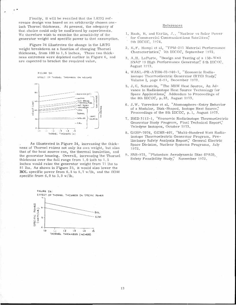
Figure 24 illustrates the change in the LRTG weight breakdown as a function of changing Thornel thickness, from 100 to 1. 5 inches. These two thickness extremes were depicted earl ier in Figure 6, and are expected to bracket the required value.
PIGUBE 11
EFFtCT Of̂ -HOtiNEL TWlClCMfcSE. ON iAJtl6HTS
^^US|N&
COLD STAc;ts ,TM6RMOC«LjPL6i -MOT S K I O E S
- INSULATION C A M
—TUORNEL
1 — CAPSUttS
— F U t L
V M E A T
) S o j a c t
TWORNEL TmCtLNESS f(N^
As illustrated in Figure 24, increasing the thickness of Thornel ra ises not only its own weight, but also that of the heat source can, the thermal insulation, and the generator housing. Overall, increasing the Thornel thickness over the full range from 1. 0 inch to 1. 5 inches would raise the generator weight from 71 lbs to 81 lbs. As shown in Figure 2 5, it would also lower the BOL specific power from 6.5 to 5.7 w/lb, and the EOM specific from 6.0 to 5.3 w/lb.
References
1. Raab, B. and Karliii, J . , "Nuclear vs Solar Power for Commercial Communications Satellites" 9th lECEC, 1974.
2. E . F . Hampl et al, "TPM-217 Material Performance Characteristics" 7th lECEC, September 1972.
3. A .n . LaPorte, "Design and Testing of a 150-Watt SNAP 19 High Performance Generator'.' 8 th lECEC, August 1973.
4. WANL-PR-AT(04-3)-940-7, "Economic Radioisotope Thermoelectric Generator (RTG) Study^ Volume I, page 6-91, December 1973.
5. J . E , Notestein, "The MHW Heat Source, An Advance in Radioisotope Heat Source Technology for Space Applications" Addendum to Proceedings of the 8th lECEC,. p. 23, August 19 73.
6. J.W, Vorreiter et al, "Atomosphere-Entry Behavior of a Modular, Disk-Shaped, Isotope Heat Source" Proceedings of the 8th lECEC, p. 1, August 1973.
7. ISED 3112-1, "Economic Radioisotope Thermoelectric Generator Study Program, Final Technical Report^ Teledyne Isotopes, October 1973.
8. GESP-7076, GEMS-407, "Multi-Hundred Watt Radioisotope Thermoelectric Generator Program, P re liminary Safety Analysis Report^ General Electric Space Division, Nuclear Systems Programs, July 1972.
9. SNS-975, "Plutonium Aerodynamic Disc (PAD), Safety Feasibility Study" November 1972.
FIGURE as :
EFFECT OF TMOKt^EL THICKWESS ON SPECinC F%I\MER
1.1 12 1.5 1.4 l.S
THORNEL TUICltMESS (IV4CHES)
13