lg_lbum7280bl exploded view
TRANSCRIPT

8/6/2019 LG_LBUM7280BL Exploded View
http://slidepdf.com/reader/full/lglbum7280bl-exploded-view 1/55
Ceiling Duct TypeAir ConditionerSERVICE MANUAL
MODELS: LB-K3660BLLB-K4260BLLB-K4880BLLB-L6080BLLB-M7280BL

8/6/2019 LG_LBUM7280BL Exploded View
http://slidepdf.com/reader/full/lglbum7280bl-exploded-view 2/55
Contents
Functions .................................................................................................................................3
Product Specifications (Cooling & Heating) ..........................................................................5
Dimensions ..............................................................................................................................7
Refrigeration Cycle Diagram ..................................................................................................9
Wiring Diagram ......................................................................................................................10
Operation Details ...................................................................................................................15
Installation of Indoor, Outdoor Unit .....................................................................................18
Cycle ........................................................................................................................................32
Cycle Troubleshooting Guide ...............................................................................................35
Electronic Parts Troubleshooting Guide .............................................................................36
Electronic Control Device .....................................................................................................39
Exploded View and Replacement Parts List .......................................................................40
–2–

8/6/2019 LG_LBUM7280BL Exploded View
http://slidepdf.com/reader/full/lglbum7280bl-exploded-view 3/55
Functions
Indoor Unit
Operation ON/OFF by Remote controller
Sensing the Room Temperature
Room temperature control
Starting Current Control
Time Delay Safety Control
Indoor Fan Speed Control
Soft Dry Operation Mode
Auto Operation(Auto Change Over)
Deice (defrost) control (Heating)
Auto Restart
–3–
Hot-start Control (Heating) • The indoor fan stops until the evaporator piping tempera-ture will be reached at 28°C.
High head height Drain pump(Optional)• A standard drain-head height of up to 700mm is possible.
Central Control(Optional) • It is operating individually or totally by central control function.
Group Control(Optional Wiring)• Each controller can control 16 units and 8 controllers can connect.
• It operates maximum 16 units by only one wired remote con-troller and each unit starts random to prevent overcurrent.
• Room temperature sensor. (Thermistor)
• Maintains the room temperature in accordance with the Setting Temp.
• Indoor fan is delayed for 5 seconds at the starting.
• Restarting is inhibited for approx. 3 minutes.
• High, Med, Low
• Intermittent operation of fan at low speed.
• Although the air-conditioner is turned off by a power failure, it is restarted automati-cally previous operation mode after power supply.
• The setting temperature and desired operation mode are auto-matically set by fuzzy rule.
• Both the indoor and outdoor fan stops during defrosting.• Hot start after defrost ends.

8/6/2019 LG_LBUM7280BL Exploded View
http://slidepdf.com/reader/full/lglbum7280bl-exploded-view 4/55
–4–
Remote Controller
Operation ON/OFF
Operation Mode Selection
Fan Speed Selection
Room Temperature Display
Temperature Setting
Setting the Timer
Weekly Program
(Coolingmodel only)
(Heatingmodel only)
(Low) (Med) (High)
Cooling Operation Mode ( )
Heating Operation Mode ( ) Auto Operation Mode ( )
Soft Dry Operation Mode ( )
Fan Operation Mode
HI AUTOMEDLO
Program Holiday
SET/CLR
MinHour
Week
T im er C an celT im er C an cel
(Except LB-E6084HL)
: High:39°C ↔ LOW:11°C
: Fan Operates without cooling & heating
Cooling HeatingDown to 18°C
Up to 30°C
Down to 16°C
Up to 30°C

8/6/2019 LG_LBUM7280BL Exploded View
http://slidepdf.com/reader/full/lglbum7280bl-exploded-view 5/55
Product Specifications (Cooling & Heating)
– 5 –
Power Source Ø, V, Hz"
Cooling Capacity kcal/h(BTU/h)
W
Input W
Heating Capacity kcal/h(BTU/h)
W
Input W
Rated Load Amp. Cooling A
Heating A
Air Volumn Cooling(H/M/L)CMM(m3 /min)
Heating(H/M/L)Refrigerant(R-22) g
Drain Hose In. Dia mm
Main CableNo. X mm2
Connecting Cable
Remote Control Type
Refigerant Control Type
Fuction Soft Dry
Timer
Self Diagnosis
Deice Operation
Hot Start
Zone Control(Optional)
Central Control(Optional)
Group Control(Optional wiring)
Weekly Programning
Thermistor
Drain Pump(Optional)
Auto changeover(Auto Operation: CL)
Stand-by Consumption 0
Connecting Pipe Liquid Inch
Gas (mm)
Dimension Indoor mm
Outdoor (W x H x D)
Net Indoor Kg
WeightOutdoor
1, 220-240, 50 1, 220-240, 50 3, 380-415, 50 3, 380-415, 50
9,072(36,000) 10,584(42,000) 12,096(48,000) 15,120(60,000)
10,551 12,309 14,067 17,585
3,600 5,100 4,900 7,000
9,072(36,000) 11,314(45,500) 12,096(48,000) 15,120(60,000)
10,551 13,190 14,067 17,585
3,400 4,700 4,400 6,500
16 22.5 8.0 12.7
14 21 7.3 12.5
35/32/28 46/38/32 49/47/44 55/50/46
35/32/28 46/38/32 49/47/44 55/50/46
2,240 3,600 3,351 4,629
22.6 22.6 22.6 22.6
3*5.5 3*8.5 4*5.5 4*5.5
5*1.25 5*1.25 5*1.25 5*1.25
L.C.D Wired L.C.D Wired L.C.D Wired L.C.D Wired
Orifice/Capil lary Orifice/Capillary Orifice/Capillary Orifice/Capillary
Yes Yes Yes Yes
24 Hours On/Off 24 Hours On/Off 24 Hours On/Off 24 Hours On/Off
Yes Yes Yes YesYes Yes Yes Yes
Yes Yes Yes Yes
Optional Optional Optional Optional
Optional Optional Optional Optional
Yes Yes Yes Yes
Yes Yes Yes Yes
Yes Yes Yes Yes
Optional Optional Optional Optional
Yes Yes Yes Yes
Yes Yes Yes Yes
3/8(9.52) 3/8(9.52) 3/8(9.52) 3/8(9.52)
5/8(15.88) 3/4(19.05) 3/4(19.05) 3/4(19.05)
1,030*350*435 1,030*350*435 1,030*350*435 1,120*400*575
870*800*320 900*1,220*370 900*1,220*370 900*1,220*370
37 37 40 51
72 90 92 92
Model LB-K3660BL LB-K4260BL LB-K4880BL LB-L6080BL

8/6/2019 LG_LBUM7280BL Exploded View
http://slidepdf.com/reader/full/lglbum7280bl-exploded-view 6/55
– 6 –
Power Source Ø, V, Hz"
Cooling Capacity kcal/h(BTU/h)
W
Input W
Heating Capacity kcal/h(BTU/h)
W
Input W
Rated Load Amp. Cooling A
Heating A
Air Volumn Cooling(H/M/L)CMM(m3 /min)
Heating(H/M/L)Refrigerant(R-22) g
Drain Hose In. Dia mm
Main CableNo. X mm2
Connecting Cable
Remote Control Type
Refigerant Control Type
Fuction Soft Dry
Timer
Self Diagnosis
Deice Operation
Hot Start
Zone Control(Optional)
Central Control(Optional)
Group Control(Optional wiring)
Weekly Programning
Thermistor
Drain Pump(Optional)
Auto changeover(Auto Operation: CL)
Stand-by Consumption 0
Connecting Pipe Liquid Inch
Gas (mm)
Dimension Indoor mm
Outdoor (W x H x D)
Net Indoor Kg
WeightOutdoor
3, 380-415, 50
18,143(72,000)
21,101
7,000
18,143(72,000)
21,101
6,800
13,0
13,0
73/68/62
73/68/626,931
22.6
4*5.5
5*1.25
L.C.D Wired
Orifice/Capillary
Yes
24 Hours On/Off
Yes
Yes
Yes
Optional
Optional
Yes
Yes
Yes
Optional
Yes
Yes
1/2(12.7)
1(22.05)
1,420*400*575
1,245*930*650
58
185
Model LB-M7280BL

8/6/2019 LG_LBUM7280BL Exploded View
http://slidepdf.com/reader/full/lglbum7280bl-exploded-view 7/55
Dimensions
– 7 –
1. Indoor
"A" "B" "C" "D" "E" "F" "G" "J" "K" "L" "M" "N" "P" "Q" "R" "S" "T" "V" "W" "X" "Y"MODEL NOLBNK3660BL
LBNK4260BL
LBNK4880BL
LBNL6080BL
1040
1040
1040
1120
350
350
350
400
56 0
56 0
56 0
58 0
282
282
282
305
712
712
71 2
71 2
282
282
282
327
868
868
868
935
366
131
131
171
234
250
250
234
-
210
210
23 9
170
170
170
183
165
161
161
165
934
934
934
1014
937
937
937
1014
548
548
548
567
40
40
40
67
120
120
120
130
22
22
22
22
79
79
79
84
972
972
972
1052
514
514
514
533
"A" "B" "C" "D" "E" "F" "G" "J" "K" "L" "M" "N" "P" "Q" "R" "S" "T" "V" "W" "X" "Y"MODEL NOLBNM7280BL 1415 400 580 303 833 327 1221 258 300 228 172 186 1313 1313 567 67 130 22 78 1351 533
"D" "F"
"X" "Y"2323
LIQUIDLINE
SUCTION
LINE
"C"
"B"
"A"
"G"
"E"
169
"T"
"W"
"S"
250
"J" "K" "L" "K"
"Q"
"P"
"R"
"M"
"N"
"M"
"N"
"J" "K" "L" "K"
"X"
"A"
"S"
250
"P"
"E"
"Q"
"G"
"T"
169"R"
LIQUIDLINE
SUCTIONLINE
"B""D"
23 23"Y"
"C"
"F"
"V""W"
(36K)
(42K/48K/60K)
(72K)

8/6/2019 LG_LBUM7280BL Exploded View
http://slidepdf.com/reader/full/lglbum7280bl-exploded-view 8/55
2. Outdoor Unit
– 8 –
Model No. a b c TYPELBUK3660BL 870 320 800 ALBUK4260BL 900 370 1220 BLBUK4880BL 900 370 1220 BLBUL6080BL 900 370 1220 BLBUM7280BL 1,245 650 930 C
Type: A Type: B Type: C
(Unit: mm)
b
a
c
b
a
c
c
b
a

8/6/2019 LG_LBUM7280BL Exploded View
http://slidepdf.com/reader/full/lglbum7280bl-exploded-view 9/55
Refrigeration Cycle Diagram
– 9 –
Heat Pump
• If 60K Model is installed at a distance of 15m, 525g of refrigerant should be added(15-7.5) x 70g = 525g
36K BTU/h 5/8" 3/8" 7.5 15 7.5 12.5 50
42K BTU/h 3/4'' 3/8" 7.5 15 7.5 12.5 70
48K BTU/h 3/4'' 3/8" 7.5 15 7.5 12.5 70
60K BTU/h 3/4'' 3/8" 7.5 15 7.5 12.5 70
72K BTU/h 1'' 1/2" 7.5 25 7.5 20 70
Capacity
Gas Liquid
Elevation B(m)Piping LengthA(m)
* AdditionalRefrigerant
(g/m)
Pipe Size (Diam-eter: Ø)
inch
Standard StandardMax. Max.
Orifice Number
Capacity Orifice Number
36K 62
42K 74
48K 86
60K 86
72K 98

8/6/2019 LG_LBUM7280BL Exploded View
http://slidepdf.com/reader/full/lglbum7280bl-exploded-view 10/55
–10–
Wiring Diagram
Model : LB-K3660BL1. Indoor
2. Outdoor
INDOORMOTOR
DRAINPUMP
BR
BR
YL
O R
R D
B L
BL
RD
B L
B L
B K
GN / Y L
GN/YL
C O M P
FUSE250V10A
T E M P .
T H E R M I S T O R
PIPETHERMISTOR
FLOAT S/W
REMOTECONTROL
ZONECONTROL
TERMINALBLOCK
7
3 ( L )
4 ( N )
5
6 T O O U T D O O R U N I T
63H2
Tmo
CM
CM
CH1
RD
GN/YL
HIGH PRESSURE SWITCH FOR HEATING
TERMINAL BLOCK
COMPRESSOR
COMPRESSOR
CRANK CASE HEATER FOR CM
RED
GREEN/YELLO
THERMISTOR FOR PIPE TEMP.
MAIN TERMINAL BLOCK
RUN CAPACITOR FOR FMo
OUTDOOR FAN MOTOR
START CAPACITOR FOR CM
WHITE
REVERSING COIL
RELAY FOR FMo
OUTDOOR FAN MOTOR
FUSE (250V, 5A)
BLUE
YELLOW
MAGNECTIC CONTACTOR
RUN CAPACITOR FOR CM
FUSE (250V, 5A)
DEICER PCB
BLACK
ORANGE
C TH
TM
Co
FMo
Cs
WH
20SV
52F1
FMo
F1
BL
YL
52S,52C
Cr
F1
D.P
BK
OR
7 8
1 TM
240V 1Ø, 50Hz
POWER SUPPLY
BK
6 3 H 2 52C
L1 L2
T1 T2
A2
A1
BK
WH
BK
52F1 1 2
3 4
5 6
WHTIMERBK
WH
YL
YL
BL
BL
WH
F1
BKWHWH
WH
20SV
WH
BK
RD
BL BL
RD
BK
BK
WH WH
BK
BK
BKGN/YL
GN/YL
Tmo T o
t h e i n d o o r u n i t
WH
G N
/ Y L
2 3
L N
1
2
3
4
5
6
BK
BK
BK
BK
BK
YL
YL
YL
BK
RD
WHRD
RD
OR
R CS
CM
CrCsFMo
BKBK
BKBKWH
52S
REACTOR
A2
A1
T3
L3
T2
L2
TNSNC NO NC NO
C TH
D.P

8/6/2019 LG_LBUM7280BL Exploded View
http://slidepdf.com/reader/full/lglbum7280bl-exploded-view 11/55
– 11 –
Model : LB-K4260BL1. Indoor
2. Outdoor
F1
S.S(A)
S.S(B)
52C(A)
52C(B) 52F1
D.P
TNS
COMP49C
R S
Tm1(L)
F1,2
49C
FMo
49FMo
BL
RD
FUSE(250V,5A)
INTERNAL O.L.P FOR COMP.
OUTDOOR FAN MOTOR
INTERNAL T.P FOR FMo
BLUE
RED
DEICER PCB.
THERMISTOR FOR PIPE TEMP.(OUTDOOR)
4-WAY VALVE COIL
START CAPACITOR FOR FMo
BLACK
WHITE
RELAY FOR COMP
RELAY FOR FMo
SOFT START PCB.
RUN CAPACITOR FOR FMo
BROWN
YELLOW
MAIN TERMINAL BLOCK
TERMINAL BLOCK FOR CONNECTING
3 PHASE DETECTOR
5 SEC. DELAY TIMER
ORANGE
GREEN/YELLOW
D.P
C TH
20SV
Cs
BK
WH
52C
52F1
S.S
Cr
BR
YL
Tm
Tmo
3.P.D
T.D
OR
GN/YL
2(N)
C
COMP49C
R SCPOWER SUPPLY1Ø,230V,50Hz~ FMo
49FMoFMo49FMo 20SV 20SV
T O I N D O OR
U N I T
CH F
Cs(A)
Cr(A)
Cr(B)
T.D
Tmo
F2
BK
BL
BK
NCNO
C TH
BK
RDRD
BKWH
WH
BK
BR
BR
BL
BL
B R
R D
B K
B L
B K
O R
B
K
O
R
Y
L
B
K
B K B K
B K B K
1 ( L ) 2 ( N )
3
4
5
O
R
O R
Y L
Y L
Y L
RD
RD
B K
CH F W H
B K B K B K
WH
WH
WH
WH
WH
W H
W H
W H W H W H
W H
Y L
YL
TB3
TB5
TB1
TB2
TB6
CN-Power
CN-Power
RY-Comp
4
3
4
4
1
3
2
5 6
7 83
4
3
4
3
RY-S/Cap
Cs(B)RY-Comp
RY-S/Cap
INDOORMOTOR
DRAINPUMP
BR
BR
YL
O R
R D
B L
BL
RD
B L
B L
B K
GN / Y L
GN/YL
C O M P
FUSE250V10A
T E M P .
T H E R M I S T O R
PIPETHERMISTOR
FLOAT S/W
REMOTECONTROL
ZONECONTROL
TERMINALBLOCK
7
3 ( L )
4 ( N )
5
6 T O O U T D O O R U N I T

8/6/2019 LG_LBUM7280BL Exploded View
http://slidepdf.com/reader/full/lglbum7280bl-exploded-view 12/55
– 12 –
Model : LB-K4880BL1. Indoor
2. Outdoor
INDOORMOTOR
DRAINPUMP
BR
BR
YL
O R
R D
B L
BL
RD
B L
B L
B K
GN / Y L
GN/YL
C O M P
FUSE250V10A
T E M P .
T H E R M I S T O R
PIPETHERMISTOR
FLOAT S/W
REMOTE
CONTROL
ZONECONTROL
TERMINALBLOCK
7
3 ( L )
4 ( N )
5
6 T O O U T D O O R U N I T
RTM
3Ø,380-415V, 50HzPOWER SUPPLY
S T N
BK
BK
BK
BK
RD
WH
WH
RD
OR
BK63H2
3.D.P
WH
WHYL
D.P C TH
TNSNO NC
WH
OR
BK52F1
52C 1
2
3
4
5
6
31T/B1
T/B2
T/B3
32B
A
FMo49FMo
FMo49FMo
YL BK
OR
BK RD
WH
CM
1 2
3 4
5 6
7 8
YL BK
OR
BK
BK
BL
BL
BL
BL
WH
WH
Co Co
20SV
BK
WH
BL
RD
GN/YL
GN/YL
TMo T o t h e i n d
o o r u n i t
1
2
3
4
5
6
BK
WHWH YL
RD
F1
BK
63H2
C TH
49FMo
20SV
CM
HIGH PRESSURE SWITCH FOR HEATING
THERMISTOR FOR PIPE TEMP.
INTERNAL T.P FOR FMo
REVERSING COIL
COMPRESSOR
52C
TM
52F1
D.P
3.D.P
MAGNECTIC CONTACTOR
MAIN TERMINAL BLOCK
RELAY FOR FMo
DEICER PCB
3 PHASE DETECTOR
Co
FMo
F1
TMo
SOL
RUN CAPACITOR FOR FMo
OUTDOOR FAN MOTOR
FUSE (250V,10A)
TERMINAL BLOCK
SOLENOID VALVE
F1
R
AB
S T
R S C

8/6/2019 LG_LBUM7280BL Exploded View
http://slidepdf.com/reader/full/lglbum7280bl-exploded-view 13/55
– 13 –
Model : LB-L6080BL1. Indoor
2. Outdoor
INDOORMOTOR
DRAINPUMP
BR
BR
YL
O R
R D
B L
BL
RD
B L
B L
B K
GN / Y L
GN/YL
C O M P
FUSE250V10A
T E M P .
T H E R M I S T O R
PIPETHERMISTOR
FLOAT S/W
REMOTE
CONTROL
ZONECONTROL
TERMINALBLOCK
7
3 ( L )
4 ( N )
5
6 T O O U T D O O R U N I T
RTM
3Ø,380-415V, 50HzPOWER SUPPLY
S T N
BK
BK
BK
BK
RD
WH
WH
RD
OR
BK63H2
WH
WHYL
D.P C TH
TNSNO NC
WH
OR
BK52F1
52C 1
2
3
4
5
6
31T/B1
T/B2
T/B3
32B
A
FMo49FMo
FMo49FMo
YL BK
OR
BK
T3T2 T1
RD
WH
CM
1 2
3 4
5 6
7 8
YL BK
OR
BK
BK
BL
BL
BL
BL
WH
WH
Co Co
20SV
SOL
BK
WH
BL
RD
GN/YL
GN/YL
TMo T o t h
e i n d o o r u n i t
1
2
3
4
5
6
BK
WHWH YL
RD
F1
BK
63H2
C TH
49FMo
20SV
CM
BL
OR
YL
HIGH PRESSURE SWITCH FOR HEATING
THERMISTOR FOR PIPE TEMP.
INTERNAL T.P FOR FMo
REVERSING COIL
COMPRESSOR
BLUE
ORANGE
YELLOW
52C
TM
52F1
D.P
3.D.P
BK
GN/YL
MAGNECTIC CONTACTOR
MAIN TERMINAL BLOCK
RELAY FOR FMo
DEICER PCB
3 PHASE DETECTOR
BLACK
GREEN/YELLOW
Co
FMo
F1
TMo
SOL
RD
WH
RUN CAPACITOR FOR FMo
OUTDOOR FAN MOTOR
FUSE (250V,10A)
TERMINAL BLOCK
SOLENOID VALVE
RED
WHITE
F1
R
AB
S T

8/6/2019 LG_LBUM7280BL Exploded View
http://slidepdf.com/reader/full/lglbum7280bl-exploded-view 14/55
– 14 –
Model : LB-M7280BL1. Indoor
2. Outdoor
BK
F1BK
BK
TNSNC NO NC NO
C TH
BK
BK BK
1 2
3 4
5 6
7 8
R
B A
S T
BK
WH
WH
WH WH
WH
WH F2
RD
RD
RD
BK
GN/YL
1 ( L ) 2 ( N )
3
4
5
Tmo
T O I N D O OR
U N I T
YL
O R
Y L
B L
BK
BL
BL
F1,2,3
49C
FMo
49FMo
Co
D.P
C TH
20SV
52C
52F1
TM
TMo
63H1
63H2
3.P.D
HIGH PRESSURE SWITCH
HIGH PRESSURE SWITCH FOR HEATING
3 PHASE DETECTOR
MAGNETIC CONTACTOR
RELAY FOR FMo
MAIN TERMINAL BLOCK
TERMINAL BLOCK FOR CONNECTING
RUN CAPACITOR FOR FMo
DEICER PCB
THETMISTOR FOR PIPE TEMP.(OUTDOOR)
4-WAY VALVE COIL
FUSE(250V,10A)
INTERNAL O.L.P FOR COMP.
OUTDOOR FAN MOTOR
INTERNAL T.P FOR FMo
20SV
Y L B R O R B K
Y L
B R
O R B K
Y L B R O R B K
Y L
B R
O R
B K
RD
1 3 5 31
2 4 6 32 A
B
R D
B K
W H
GN/YL
F3
Tm
Co
FMo49FMo
FMo49FMo COMP
49C
Co
T1 T3 T2
POWER SUPPLY3Ø,380-415,50HzTERMINAL(4P)
R S T N
63H1
63H2
52C
52F1
3.P.D
D.P
RD
INDOORMOTOR
DRAINPUMP
BR
BR
YL
O R
R D
B L
BL
RD
B L
B L
B K
GN / Y L
GN/YL
C O M P
FUSE250V10A
T E M P .
T H E R M I S T O R
PIPETHERMISTOR
FLOAT S/W
REMOTE
CONTROL
ZONECONTROL
TERMINALBLOCK
7
3 ( L )
4 ( N )
5
6 T O O U T D O O R U N I T

8/6/2019 LG_LBUM7280BL Exploded View
http://slidepdf.com/reader/full/lglbum7280bl-exploded-view 15/55
– 15 –
Operation Details
(1) The function of main control
1. Time Delay safety Control
• 3min... The compressor is ceased for 3minutes to balance the pressure in the refrigeration cycle.
(Protection of compressor)• 30sec... The 4-way valve is ceased for 30sec. to prevent the refrigerant-gas abnormal noise when the Heating
operation is OFF or switched to the other operation mode while compress is off.
While compressor is running, it takes 3~5 seconds to switch.
2. Soft-Dry Operation
• The indoor fan speed is automatically set to the low, so the shift of the indoor fan speed is impossible because of
already being set to the best speed for Dry Operation by Micom Control.
3. Cooling Mode Operation
• When selecting the Cooling( ) Mode Operation, the unit will operate according to the setting by the remote con-troller and the operation diagram is as following.
Intake Air temp.
SET TEMP.+0.5°C
(COMP. ON)
SET TEMP. -0.5°C
(COMP. OFF) More than More than
3 minutes 3 minutes
Selecting Selecting Selecting
fan speed fan speed fan speed
COMPRESSOR ON OFF ON OFF ON
INDOOR FAN Low Low

8/6/2019 LG_LBUM7280BL Exploded View
http://slidepdf.com/reader/full/lglbum7280bl-exploded-view 16/55
– 16 –
Intake Air temp.
Setting temp.+3°C(Compressor OFF)
Setting temp.
(Compressor ON)
INDOOR FAN Low OFF Low Low OFF
COMPRESSOR ON OFF ON OFF
• A point; While the indoor Heat-Exchanger temperature is higher than 40°C fan operates at low speed, when
it becomes lower than 40˚C fan stops.
• B point; When the indoor Heat-Exchanger temperature is higher than 42°C, fan operates at seleted fan
speed, when it becomes lower than 39°C, the fan operates at low speed.
4. Heating Mode Operation (Except Cooling Model)The unit will operate according to the setting by the remote controller and the operation diagram is shown as following.
Hot Start Low SelectingFan Speed
minimum 3min
Selecting fanspeed
minimum
10sec.
1min
A A
minimum
10sec.
B
5. Hot-Start Control
• The indoor fan stops until the evaporator piping temperature will be reached to 31 °C.
• The operation diagram is as following.
PIPINGTEMPERATURE
1min
COMPRESSOR
INDOOR FAN
ON
28°C
: Selected Fan : Low Fan : Fan Stop
31°C

8/6/2019 LG_LBUM7280BL Exploded View
http://slidepdf.com/reader/full/lglbum7280bl-exploded-view 17/55
– 17 –
6. Defrost Control• Defrost control is availavle 45 minutes later since heating mode operation started, and it will not prolong over
10 minutes.
• Defrost control is carried out when the outdoor pipe temp. falls below -6°C for more than 3 minutes after 45
minutes passed from starting of heating operation.
• Defrost ends after 10 minutes passed from starting of defrost operation or when the outdoor pipe temp. rises
over 12°C after 5 minutes passed from starting of defrost.
7. Self-diagnosis Function• 'CHECK' will flash in the remote controller display when a problem occurs. Then please contact your dealer.
• Correct the accident point as shown in the table below before restarting operation.
• During the normal operation 'CHECK' won't be displayed in the remote controller.
Remote controller LCD Accident Point
CH 01 Indoor room temperature thermistor error
CH 02 Indoor piping thermistor error
CH 03 Indoor main body / Remote controller unit communication error
CH 04(Optional) Water level float switch error
More than 45 minutesof heating operation
Within9min. 45sec.
ON OFF
ON ON
ON
ON OFF
OFFCOMPRESSOR
4-WAY VALVE
INDOOR FAN
-6°C ON
12°C OFF
The outdoorpiping Temp.
ON
More than 10 min.running of compressor
More than 45 minutesof heating operation
5sec.
HOT-
START
ON

8/6/2019 LG_LBUM7280BL Exploded View
http://slidepdf.com/reader/full/lglbum7280bl-exploded-view 18/55
– 18 –
Installation of Indoor, Outdoor Unit
1. Selection of the best location1) Indoor unit
Select location
Install the air conditioner in the location that satis-fies the following conditions.
• The place shall easily bear a load exceeding four
times the indoor unit’s weight.
• The place shall be able to inspect the unit as the
figure.
• The place where the unit shall be leveled.
• The place shall allow easy water drainage.(Suit-
able dimension “H” is necessary to get a slope to
drain as figure.)
• The place shall easily connect with the outdoor
unit.
• The place where the unit is not affected by anelectrical noise.
• The place where air circulation in the room will be
good .
• There should not be any heat source or steam
near the unit.
2) Outdoor unit • If an awning is built over the unit to prevent direct
sunlight or rain exposure, be careful that heat
radiation from the condenser is not restricted.
• There should not be any animals or plants which
could be affected by hot air discharged.• Ensure the spaces indicated by arrows from the
wall, ceiling, fence or other obstacles.
3) Piping length and the elevation
Indoor unit
Outdoor unitB
A
More than30cm
More than30cm
More than70cm
S u n r o o f
Fence orobstacles
Top view(unit: mm)
H
Front view
600600
Front
Inspection hole
(600X600)
Control box
1 0 0 0
36K BTU/h 5/8" 3/8" 7.5 15 7.5 12.5 50
42K BTU/h 3/4'' 3/8" 7.5 15 7.5 12.5 70
48K BTU/h 3/4'' 3/8" 7.5 15 7.5 12.5 70
60K BTU/h 3/4'' 3/8" 7.5 15 7.5 12.5 70
72K BTU/h 1'' 1/2" 7.5 25 7.5 20 70
Capacity
Gas Liquid
Elevation B(m)Piping LengthA(m)
* AdditionalRefrigerant
(g/m)
Pipe Size (Diam-eter: Ø)
inch
Standard StandardMax. Max.

8/6/2019 LG_LBUM7280BL Exploded View
http://slidepdf.com/reader/full/lglbum7280bl-exploded-view 19/55

8/6/2019 LG_LBUM7280BL Exploded View
http://slidepdf.com/reader/full/lglbum7280bl-exploded-view 20/55
– 20 –
3. Remote Controller Installation
• Although the room temperature sensor is in the indoor unit, the remote controller should be installed
in such places away from direct sunlight and high humidity.
Installation of the remote controller
• Select places that are not splashed with water.
• Select control position after receiving customer approval.
• The room temperature sensor is built in the indoor unit.• This remote controller equipped with liquid crystal display. If this position is higher or lower, display is difficult
to see.(The standard height is 1.2 ~ 1.5m high)
Routing of the remote controller cord
• Keep the remote controller cord away from the refrigerant piping and the drain piping.
• To protect the remote controller cord from electrical noise, place the cord at least 5cm away from other power
cables (audio equipment, television set, etc.)
• If the remote controller cord is secured to the wall, provide a trap at the top of the cord to prevent water
droplets from running.
Remote control
box body
Cord clamp
(accessory)
Lever carefullythe box openusing a screw
driver, etc.
Front case
T h e l o w e r p a r t
Face of wall
Under plate
Screw (accessory)
• Fix the under plate on the wall
• Separate the under plate from Remote control box.
• Fix the cord clamps on the wall by ø 3 tappingscrews (accessory).
• Fix the remote control cord.
WIRED REMOTE CONTROL INSTALLATION
DISASSEMBLING
ELECTRICAL WIRING
Wire and make sure that teminal
numbers are matched on unit side andremote controller side.
The maximum length of the cord is 100m.If the length of the cord exceeds 50m,
use a wire size greater than 0.5mm2.
Remote controller
(Main board)
CN REMO

8/6/2019 LG_LBUM7280BL Exploded View
http://slidepdf.com/reader/full/lglbum7280bl-exploded-view 21/55
– 21 –
Remove the battery cover from the remote controller.
• Slide the cover according to the arrow direction.
Insert the two batteries.
• Be sure that the (+) and (-) directions are correct.
• Be sure that both batteries are new.
Re-attach the cover.
• Slide it back into position.
• Do not use rechargeable batteries,
such batteries differ from standard
dry cells in shape, dimensions, and
performance.
• Romove the batteries from the
remote controller if the air condi-
tioner is not going to be used for
some long time.
REMOTE CONTROL PREPARATION(OPTIONAL)
HOW TO MOUNT ONTO A WALL
HOW TO INSERT BATTERIESHOW TO INSERT BATTERIES

8/6/2019 LG_LBUM7280BL Exploded View
http://slidepdf.com/reader/full/lglbum7280bl-exploded-view 22/55
4. Connecting Cables between Indoor Unit and Outdoor Unit
– 22 –
1) Connecting cables to the Indoor Unit Connect the wires to the terminals on the control board individually according to theoutdoor unit connection.• Ensure that the color of the wires of outdoor unit and the terminal No. are the same as
those of indoor unit respectively
36K/42K/48K/60K/72K Btu
2) Clamping of cables 1) Arrange 2 power cables on the control panel.2) First, fasten the steel clamp with a screw to the inner boss of control panel.3) For the cooling model, fix the other side of the clamp with a screw strongly.
For the heat pump model, put the 1.25mm2 cable(thinner cable) on the clamp and tighten itwith a plastic clamp to the other boss of the control panel.
4) In Australia, the length of power supply cord measured from the entry of the power supplycord to the middle of live pin on the power plug should be over 1.8m.
POWER INPUT
• Cooling & Heating type (380-415V3N~) (220-240V~)
Terminals on the indoor unit 1 2 4 53
Terminals on the outdoor unit 1 2 4 53
1(L) 2(N)
POWER INPUT
R S T N
The power cord connected to the outdoor unit should becomplied with the following specifications (Rubber
insulation, type H05RN-F approved by HAR or SAA).
If the supply cord is damaged, it must be replaced by a special cord or assembly availible from the manufacturer of its service agent.
The connecting cable connected to the indoor and outdoorunit should be complied with the following specifications
(Rubber insulation, type H05RN-F approved by HAR or SAA).
CAUTION
2 0 m m
G N / Y L
NORMAL
CROSS-SECTIONAL
AREA 1.25mm2 (36K/42K/48K/60K/72K)
2 0 m m
G N / Y L
NORMAL CROSS-SECTIONAL AREA
Capacity36K BTU/h42K BTU/h48K BTU/h
72K BTU/h
60K BTU/h
1 Phase
5.5mm2
8.5mm2
–
–
3 Phase
-
-
5.5mm2
5.5mm2
5.5mm2
Make sure that the screws of the terminal are free from looseness.
WARNING

8/6/2019 LG_LBUM7280BL Exploded View
http://slidepdf.com/reader/full/lglbum7280bl-exploded-view 23/55
– 23 –
Outdoor
Indoor
Control box cover(On which the Electric
Wiring Connection is put)
Main terminal board
Control terminal board
Cordclamper
Cover control
A
A view
Remotecontrol cord
Connectioncord betweenthe indoor unitand theoutdoor unit
Cord clamper
Mainpower source
Switch box
Circuit Breaker
Control terminal board
Control box
ELECTRICAL WIRINGPerform the electrical wiring work according to the electricalwiring connection.
• All wiring must comply with local requirements.• Select a power source that is capable of supply-
ing the current required by the air conditioner.• Use a recognized circuit breaker between the
power source and the unit. A disconnectiondevice to adequately disconnect all supply linesmust be fitted.
• Capacity of circuit breaker
INDOOR UNIT
• Remove the control box cover for elec-trical connection between the indoorand outdoor unit.
• Use the cord clamper to fix the cord.
WIRING CONNECTION
OUTDOOR UNIT
• Remove the control cover for wiring con-nection.
• Use the cord clamper to fix the cord.• Earthing work
Connect the cable of diameter 1.6mm2
or more to the earthing terminal provid-ed in the control box and do earthing.
Please check !!
Capacity 1 Phase 3 Phase
36K BTU/h 35A -
42K BTU/h 40A -
48K BTU/h - 25A
60K BTU/h - 25A
72K BTU/h - 25A

8/6/2019 LG_LBUM7280BL Exploded View
http://slidepdf.com/reader/full/lglbum7280bl-exploded-view 24/55
1) Cut the pipes and the cable.
s Use the accessory piping kit or the pipes purchasedlocally.s Measure the distance between the indoor and the out-
door unit.s Cut the pipes a little longer than measured distance.s Cut the cable 1.5m longer than the pipe length.
2) Burrs removal s Completely remove all burrs from the cut cross section
of pipe/tube.s Put the end of the copper tube/pipe to downward direc-
tion as you remove burrs in order to avoid to let burrs
drop in the tubing.
3) Putting nut on s Remove flare nuts attached to indoor and outdoor units,
than put them on pipe/tube having completed burrremoval.(Not possible to put them on after flaring work)
4) Flaring work s Carry out flaring work using flaring tool as shown below.
Firmly hold copper tube in a bar(or die) as indicateddimension in the table above.
5) Check s Compare the flared work with figure below.s If flare is noted to be defective, cut off the flared section
and do flaring work again.
– 24 –
Coppertube 90° Slanted Uneven Rough
Pipe
Reamer
Point down
Flare nut
Copper tube
Bar
Copper pipe
Clamp handleRed arrow mark
Cone
Yoke
Handle
Bar"A"
Inclined
Inside is shining without scratches.
Smooth all round
Even lengthall round
Surfacedamaged
Cracked Uneventhickness
= Improper flaring =
• Preparation of Piping
5. Connecting Pipes to the Indoor Unit
Main cause of gas leakage is defect in flaring work. Carry out correct flaring work in the following procedure.
Outside Diameter " A "
Gas Liquid Gas Liquid
36K BTU/h 5/8" 3/8" 0.8~1.0 0.5~0.8
42K BTU/h 3/4" 3/8" 1.0~1.3 0.5~0.8
48K BTU/h 3/4" 3/8" 1.0~1.3 0.5~0.8
60K BTU/h 3/4" 3/8" 1.0~1.3 0.5~0.8
72K BTU/h 1" 1/2" - -
Capacity

8/6/2019 LG_LBUM7280BL Exploded View
http://slidepdf.com/reader/full/lglbum7280bl-exploded-view 25/55
– 25 –
1. Form the piping according to its routing. Avoid bend-
ing and bending back the same piping point more
than three times. (This will result in hardening the
pipe.)
2. After deforming the piping, align centers of the union
fitting of the indoor unit and the piping, and tightenthem firmly with wrenches.
3. Connect pipe to the service valve or ball valve which
is located below the outdoor unit.
4. After completing the piping connection, be sure to
check if there is gas leakage in indoor and outdoor
connection.
After completing the piping connection, execute vacuum
drying for the connecting piping and the indoor unit.The vacuum drying must be carried out using the ser-
vice ports of both the liquid and gas side valves.
Use two wrenches and tighten with regular torque.
Outdoorunit
Liquid side
Flare connection
Flare connection
Gas side
Indoor
unit
UnionFlare nut fastening torque
Ø6.35mm 1.8kg.m
Ø9.52mm 4.0kg.m
Ø12.7mm 5.5kg.m
Ø15.88mm 6.6kg.m
Ø19.05mm 6.6kg.m
Model Liquid side piping Gas side piping
36K Btu/h 3/8" 5/8"
42K Btu/h 3/8" 3/4"
48K Btu/h 3/8" 3/4"
60K Btu/h 3/8" 3/4"
72K Btu/h 1/2" 1"
Piping Connection
Vacuum drying
CAUTION

8/6/2019 LG_LBUM7280BL Exploded View
http://slidepdf.com/reader/full/lglbum7280bl-exploded-view 26/55
– 26 –
Ceiling
CAUTION
1 ~ 3 m m
Drainage hole
Drainage hole
U-Trap
BC
A ≥ 70mmB ≥ 2C
C≥
2 x SPSP = External Pressure(mmAq)
Ex) External Pressure= 10mmAqA ≥ 70mmB ≥ 40mmC ≥ 20mm
A
Make sure to be closed.
Unit
Drainage pipe(Local supply)
Thermal insulator
(Local supply)
Drainage hole
CAUTION FOR GRADIENT OF
UNIT AND DRAIN PIPING
Lay the drain hose with a downwareinclination so water will drain out.
700mm
(HP/CP model only)
Front of view
• Always lay the drain with downward inclination(1/50 to 1/100).Prevent any upward flow or reverse flow in any part.
• 5mm or thicker formed thermal insulator shallalways be provided for the drain pipe.
1. Install declination of the indoor unit is very important for the drain of the duct type air conditioner.
2. Minimum thickness of the insulation for the connecting pipe shall be 5mm.
• The unit must be horizontal or declined to the drain hose connected when finished installation.
CORRECT
INCORRECT
• Upward routing notallowed
Applied U-Trap Dimension
• Install the P-Trap (or U-Trap) to preventa water leakage caused by the blockingof intake air filter.
INCORRECTCORRECT

8/6/2019 LG_LBUM7280BL Exploded View
http://slidepdf.com/reader/full/lglbum7280bl-exploded-view 27/55
– 27 –
• Drill the piping hole with 70mm dia, holecore drill.
• Piping hole should be slightly slant to theoutdoor side.
INSULATION, OTHERS Insulate the joint and tubes completely.
All thermal insulation must comply with local requirement.
INDOOR UNIT
REFRIGERANT PIPE • Insulate and tape both the gas piping and liquid piping.
THERMAL INSULATION
5~7mm
Indoor OutdoorWALL
Make sure that there is no clearance here.
Overlap with thermal
insulator for piping.
Thermal insulator for refrigerant pipe(Local supply) Thermal insulator for
piping(Local supply)
Hose crip for thermal insulator(Local supply)
Union for liquid pipe
OrificeRefrigerant pipe and thermalinsulator(Local supply)
Union for gas pipe
Thermal insulator for refrigerant pipe(Local supply)
Hose crip for thermal insulator(Local supply)
Connecting cable
Liquid pipe
Thermal insulator
Gas pipe
Tape

8/6/2019 LG_LBUM7280BL Exploded View
http://slidepdf.com/reader/full/lglbum7280bl-exploded-view 28/55
1. Wrap the connecting portion of indoor unit withthe Insulation material and secure it with twoPlastic Bands. (for the right pipings)• If you want to connect an additional drain hose,
the end of the drain-outlet should keep distancefrom the ground. (Do not dip it into water, and fixit on the wall to avoid swinging in the wind.)
2. Tape the Pipings, drain hose and ConnectingCable from bottom to top.
3. Form the pipings gathered by taping along theexterior wall and fix it onto the wall by saddleor equivalent.
– 28 –
1) PRECAUTIONS IN TEST RUN • The initial power supply must provide at least 90% of the rated voltage.
Otherwise, the air conditioner should not be operated.For test run, carry out the cooling operation firstly even during heating season. If heating operationis carried out firstly, it leads to the trouble of compressor. Then attention must be paid.Carry out the test run more than 5 minutes without fail.(Test run will be cancelled 18 minutes later automatically)
• The test run is started by pressing the room temperature checking button and down timer button for 3 sec-onds at the same time.
• To cancel the test run, press any button.
• After completing work, be sure to measure and record trial run properties, and store measured data, etc.• Measuring items are room temperature, outside temperature, suction temperature, blow out temperature, wind
velocity, wind volume, voltage, current, presence of abnormal vibration and noise, operating pressure, pipingtemperature, compressive pressure.
• As to the structure and appearance, check following items.
CHECK THE FOLLOWING ITEMS WHEN INSTALLATION IS COMPLETE
Caution
Is the circulation of air adequate?Is the draining smooth?Is the heat insulation complete(refrigerant and drain piping)?
Is there any leakage of refrigerant?
Is the remote controller switch operated?Is there any faulty wiring?Are not terminal screws loosened?
M4...118N.cm12kgf.cm M5...196N.cm20kgf.cmM6...245N.cm25kgf.cm M8...588N.cm60kgf.cm
Test running
Trap is required to prevent water from enteringinto electrical parts.
Seal a small openingaround the pipingswith gum type sealer.
Drain hose
Taping
Pipings
Connectingcable
Power supplycord
In case of the Outdoor unit being installedbelow position of the Indoor unit.
FORM THE PIPINGS

8/6/2019 LG_LBUM7280BL Exploded View
http://slidepdf.com/reader/full/lglbum7280bl-exploded-view 29/55
– 29 –
CAUTION
After the confirmation of the above conditions, prepare the wiring as follows:
1) Never fail to have an individual power specialized for the air conditioner. As for the method of wiring,
be guided by the circuit diagram pasted on the inside of control box cover.
2) Provide a circuit breaker switch between power source and the unit.
3) The screw which fasten the wiring in the casing of electrical fittings are liable to come loose from
vibrations to which the unit is subjected during the course of transportation. Check them and
make sure that they are all tightly fastened. (If they are loose, it could give rise to burn-out of the
wires.)
4) Specification of power source
5) Confirm that electrical capacity is sufficient.
6) Be sure that the starting voltage is maintained at more than 90 percent of the rated voltage marked
on the name plate.
7) Confirm that the cable thickness is as specified in the power sources specification.
(Particularly note the relation between cable length and thickness.)
8) Never fail to equip a leakage breaker where it is wet or moist.9) The following troubles would be caused by voltage drop-down.
• Vibration of a magnetic switch, damage on the contact point there of, fuse breaking, disturbance to the
normal function of a overload protection device.
• Proper starting power is not given to the compressor.
2) Connection of power supply 1. Connect the power supply cord to the independent power supply.
• Circuit breaker is required.
2. Operate the unit for fifteen minutes or more.
3) Evaluation of the performance 1. Measure the temperature of the intake and discharge air.
2. Ensure the difference between the intake temperature and the discharge one is more than 8°C (Cooling) orreversely (Heating).

8/6/2019 LG_LBUM7280BL Exploded View
http://slidepdf.com/reader/full/lglbum7280bl-exploded-view 30/55
– 30 –
Optional Operation1) Two Thermistor System
(1) Open the rear cover of the wired remote-controller to set the mode.
(2) Select one of three selectable modes as follows.
• Position 1:
The room temperature is controlled by the thermistor of the main body.• Position 2:
The room themperature is controlled by the thermistor of the wired remote-controller, control the
temperature according to the position of wired remote-controller.
• Position 3:
The room temperature is controlled by lower temperature between the temperature of main body and of
remote-controller sensor.
(3) Move the slide switch to set position.
(4) Close the rear cover and check if it works normally.
TH
R14HSW TH
REMOMAIN2TH OP7
R18HR17H
OP6
LOSTAND
S W H IG H
HI R03S
C 0 7 0
R 0 4 S
R 0 2 S
R01S
OP3 O P 2 O P1R19H
R11H
R 13H R 12H O P5 R 16 H O P 4
R15H
CO1H
REMO
Room Temp. sensor
2TH
MAIN
Position 2
Position 1
Position 3
Slide switch for 2 Thermistor
• Select the position after counselling with a customer.
• In case of cooling mode, room temperature is controlled by the main body sensor.
• To control the room temperature by a wired remote controller, install controller(room temp. sensor) to sense
the temperature more accurately.
• Maunfactured in the position 1.
CAUTION

8/6/2019 LG_LBUM7280BL Exploded View
http://slidepdf.com/reader/full/lglbum7280bl-exploded-view 31/55
– 31 –
2) Group Control(Optional Wiring)
• You can use a group control operation after connecting the brown and yellow wire of each air-conditioner.
• Remove the resistor "OP 7" in remote controller.
• It operates maximum 16 Units by only one Wired Remote Controller,
and each Unit starts sequentially to prevent overcurrent.
Wiring design
Features
• Use Only One Wired Remote Controller with several air conditioners(max. 16 Units)
• Random starting to prevent overcurrent.
Operation unit
ZONE 1 2 3 4
HumidifyJETAUTO
AUTO SWING OPERATION FAN SPEED
Program set
SUB FUNCTIONSET TEMPRoomTemp
HIMED
LO
HeaterDefrostFilter
Preheat
Out door
Time
TimerOn
Setno.Time
Off0 1 0 3 0 5 0 7 0 9 1 1 1 3 1 5 1 7 1 9 2 1 2 3
Indoor Unit 1
Terminal(Local Supply)Block
Terminal(Local Supply)Block
Terminal(Local Supply)Block
Main PCB#1
Main PCB#2
Main PCB#16
Wired Remote Controller
Slide Switch OP7
RemoteController
PCB
Indoor Unit 2
Main PCB
Indoor Unit 16
ConnectorRED(12V)
YL(SIGNAL)
BR(GND)
RED(12V)
YL(SIGNAL)
BR(GND)
YL(SIGNAL)
BR(GND)
YL(SIGNAL)
BR(GND)YL(SIGNAL)
BR(GND)
YL(SIGNAL)
BR(GND)
Connecting Cable(Local Supply)
Connector Connector
....
....
• Be careful not to exchange the color of wires.• The maximum length of connecting wire should be below 200m(25Ω) on connecting each units.• Use a wire more than 0.5mm2
CAUTION

8/6/2019 LG_LBUM7280BL Exploded View
http://slidepdf.com/reader/full/lglbum7280bl-exploded-view 32/55
Cycle
1. Installation (Connecting the piping between indoor and outdoor unit)
–32–
• Installation
(1) Connect the piping between the indoor and
outdoor unit firmly.
– Incorrect connection may cause the leakage and
incomplete vacuuming.
(2) Attach the charging hose (manifold gage) to the
service port.
– Charging hose is necessary to check the pressure
and to inject R22 for leakage test.
– The valve of charging hose must be closed before
being connected.
(3) Inject the 100~300g R22 through the charging hose
opening the valve.
(4) Check the joint part using a gas detector or soapy
water for leakage.
– On checking, the service valve of main service port
must be closed, this test is only for checking whether
pipe connection is ok or not.
(5) If there is no leakage, discharge R22 in piping
completely into tank for retrieving.
– Complete discharge is needed for vacuuming.
– If leakage is found, please fasten the joint more
tightly.
(6) After closing the valve of charging hose,
disconnect the tank and connect the vacuum pump
to charging hose and open the valve again for
vacuuming.
(7) Turn on the vacuum pump until the pressure drops
below 0kg/cm2.
(8) After vacuuming, disconnect the vacuum pump and
open the spindle of service port (liquid-side)
slightly for 30 sec and then open the spindle of
(gas side) with hexagonal wrench.
(9) Open the liquid side completely first and then the
gas side fully in order.
Lo
Purge the air
Outdoor unit
Indoor unit Liquid side
Gas side
Gas cylinder
R22

8/6/2019 LG_LBUM7280BL Exploded View
http://slidepdf.com/reader/full/lglbum7280bl-exploded-view 33/55
2. Disconnection (on moving)
• Disconnection
(1) Attach the charging hose (manifold gage) to
the service port.
– Connect the manifold gage once to the service
port not stopping. Stopping in the middle of
process may cause the leakage.
(2) Purge the air in hose into special device such
as retrieving tank opening the valve of
charging- hose (gas side) slightly and then
close it tightly.
(3) Operate the air conditioner for 10~15 min until
cycle is stabilized.
(4) Close the spindle of service port (liquid side-
high pressure) and wait till pressure of gas
side (low pressure) drops below 0kgf/cm2.
(5) After the needle of gage indicates below
0 kgf/cm2, close the valve of gas side quickly
and turn off the power.
(6) Disconnect the piping between indoor and
outdoor unit and then put on service cap to
the service port.
Lo
Outdoor unit
Indoor unit Liquid side
Gas side
Retrieving Tank
– 33 –

8/6/2019 LG_LBUM7280BL Exploded View
http://slidepdf.com/reader/full/lglbum7280bl-exploded-view 34/55
3. Gas Charging
(After Evacuation)
• Procedure
(1) Connect the charge hose to the charging
cylinder.
– Connect the charge hose which you dis-
connected from the vacuum pump to the valveat the bottom of the cylinder.
– If you are using a gas cylinder, also use a scale
and reverse the cylinder so that the system can
be charged in liquid state.
(2) Purge the air from the charge hose.
– Open the valve at the bottom of the cylinder
and press the check valve on the charge set to
purge the air. (Be careful of the liquid
refrigerant). The procedure is the same if
using a gas cylinder.
(3) Open the valve (Lo side on the charge set andcharge the system with liquid refrigerant.
– If the system can not be charged with the
specified amount of refrigerant, it can be
charged with a little at a time (approximately
150g each time) while operating the air
conditioner in the cooling cycle; however, one
time is not sufficient, wait approximately 1
minute and then repeat the procedure.
(4) Immediately disconnect the charge hose from
the 3-way valve’s service port.
– Stopping partway will allow the gas to be
discharged.
– If the system has been charged with liquid
refrigerant while operating the air conditioner,
turn off the air conditioner before disconnecting
the hose.
(5) Mount the valve stem nuts and the service
port nut.
– Use torque wrench to tighten the service port
nut to a torque of 1.8 kg.m.
– Be sure to check for gas leakage.
\
This is different from previous procedures.
Because you are charging with liquid refrigerant
from the gas side, absolutely do not attempt to
charge with larger amounts of liquid refrigerantwhile operating the air conditioner.
Lo
Chargingcylinder
Outdoor unit
Indoor unit Liquid side
Gas side
CLOSE
Open2-Wayvalve
3-Wayvalve
OPEN
Open
Check valve
(1)
– 34 –

8/6/2019 LG_LBUM7280BL Exploded View
http://slidepdf.com/reader/full/lglbum7280bl-exploded-view 35/55
Cycle Troubleshooting Guide
Trouble analysis
1. Check temperature difference between intake and discharge air and operating current.
Temp. Difference
Temp. difference : approx. 0°CCurrent : less than 80% of
rated current
Temp. difference : approx. 8°CCurrent : less than 80% of
rated current
Temp. difference : less than 8°C
Current : over the ratedcurrent
Temp. difference : over 8°C
Operating Current
All amount of refrigerant leaked out
Check refrigeration cycle
Refrigerant leakege
Clog of refrigeration cycle
Defective compressor
Excessive amount of refrigerant
Normal
Notice :
Temperature difference between intake and discharge air depends on room air humidity. When the room air
humidity is relativery higher, temperature difference is smaller. When the room air humidity is relatively lower
temperature difference is larger.
2. Check temperature and pressure of refrigeration cycle.
Notice :
1. The suction pressure is usually 4.5~6.0 kg/cm2G at normal condition.
2. The temperature can be measured by attaching the thermometer to the low pressure tubing and wrap it with
putty.
Suction pressure Temperature(Compared with (Compared with Cause of Trouble Description
the normal value) the normal value)
Defective compressor Current is lowDefective 4-way reverse valve
Excessive amount of High pressure does not quicklyNormal refrigerant rise at the beginning of
operation
Insufficient amount of Current is lowLower Higher refrigerant (Leakage)
Clogging Current is low
High
Higher
– 35 –

8/6/2019 LG_LBUM7280BL Exploded View
http://slidepdf.com/reader/full/lglbum7280bl-exploded-view 36/55
Electronic Parts Troubleshooting Guide
: The unit does not operate.Possible Trouble 1
– 36 –
YES
NO
YES
Is the input voltageof transformer AC230V?
Check the FUSEand the wiring diagram.
Is the PIN 49,58 ofMICOM. DC5V?
Exchange MICOM.
YES
NO Check the main P.C.Bpattern.
NO
YES
Is the output voltageof IC03D DC5V?
NOExchange IC03D.
Is the input voltageof IC03D about AC12V?
Check the5V P.C.B pattern.

8/6/2019 LG_LBUM7280BL Exploded View
http://slidepdf.com/reader/full/lglbum7280bl-exploded-view 37/55
Possible Trouble 2 : The indoor fan does not operate.
– 37 –
NO
NO
Is it the HOTSTART mode?
Is IC01M operatednormally?
Check the fan motorand connector.(CN-MOTOR)
YES
Is the each Relayany problem?
YES
NO
YES
It is normal operation.
Exchange IC01M.
Exchange Relay.
YES
YES
NO
YES
Is it Heating Mode?
Does the temperatureset all right?
Change IC01M.
NO
NO
Adjust operation mode.
Adjust set temperature.
Is IC01M operatednormally?
YES
Check the connector.(CN-OUT)
Check RY-4Way.NO
Is 4way-valve operated?
Possible Trouble 3 : Ineffective Heating

8/6/2019 LG_LBUM7280BL Exploded View
http://slidepdf.com/reader/full/lglbum7280bl-exploded-view 38/55
– 38 –
Possible Trouble 4 : Wired remote controller does not operate.
NO
YES
YES
YES
Is the LCD operatednormally?
Is the terminal of wiredRemocon T2 DC12V?
Is the pin 39, 40 ofMicom DC 5V?
Change the wired Remocon.
Check the wired RemoconPCB and DC 12V pattern.
NO
NO
Check the parts ofcommunication.
Connector CN-Remo, andterminals of wiredRemocon exactly.

8/6/2019 LG_LBUM7280BL Exploded View
http://slidepdf.com/reader/full/lglbum7280bl-exploded-view 39/55
– 39 –
Electronic control device
s MAIN P.C.B ASM

8/6/2019 LG_LBUM7280BL Exploded View
http://slidepdf.com/reader/full/lglbum7280bl-exploded-view 40/55
–40–
Exploded View and Replacement Parts List
1. Indoor Unit
Model:LBNK3660BL 237203
330870W3001-1
W4811
137211-1
137211-2
237204-4
268714
249941-2
249941-1
237201
237204-1
237204-2
W3001-2
237200
267110-1
354212
237204-3
W3300
359012
W6640
346810
349480

8/6/2019 LG_LBUM7280BL Exploded View
http://slidepdf.com/reader/full/lglbum7280bl-exploded-view 41/55
–41–
354212EVAPORATOR ASSEMBLY,FINAL 5421A90024A
REVAPORATOR ASSY 75094001
359012FAN ASSEMBLY,BLOWER 5901A20022A
RBLOWER ASSY DDC241T181-204
237201PANEL,BASE 3720A20210A
RPANEL BASE XP0023-055
137211-1PANEL ASSEMBLY,FRONT(INDOOR) 3721A20130A
RPANEL ACCESS XP0023-056
237204-1PANEL,SIDE 3720A20211A
RPANEL CORNER BLH XP0023-059
237204-2PANEL,SIDE 3720A20211B
R
PANEL CORNER BRH XP0023-060W3001-1
ANGLE ASSEMBLY 3001A20003AR
ANGLE SPIGOT COIL XP0023-061
237203PANEL,UPPER 3720A20208A
RPANEL TOP XP0023-062
W3001-2ANGLE ASSEMBLY 3001A20003B
RANGLE SPIGOT BLOWER XP0023-063
330870DRAIN PAN ASSEMBLY 3087A20015A
RDRAIN TRAY ASSY XP0023-064
237204-3PANEL,SIDE 3720A20211C
RPANEL CORNER FLH XP0023-100
237204-4PANEL,SIDE 3720A20211D
R
PANEL CORNER FRH XP0023-102249941-1
CONTROL BOX,INDOOR 4994A20068AR
CONTROL BOX XP0023-105
249941-2CONTROL BOX,INDOOR 4994A20068B
RCONTROL BOX COVER XP0023-106
W4811BRACKET ASSEMBLY 4811A20026A
RBRACKET MOUNTING XP0023-107
237200PANEL,CONTROL 3720A20209A
RPANEL ACCESS CNTRL XP0023-099
W6640TERMINAL BLOCK 6640W3A009C
RTERMINAL STRIP LNX14613
W3300PLATE 3300A20029A
R
PLATE COVER XP0023-101137211-2
PANEL ASSEMBLY,FRONT(INDOOR) 3721A20130BR
PANEL BLOWER MTG. XP0023-119
346810MOTOR ASSEMBLY,INDOOR 4681A20096A
RMOTOR HF2J4701K
267110-1REMOTE CONTROLLER ASSEMBLY 6711A10002W
RCONTROL KIT (FOC) K0023-25
268714PWB(PCB) ASSEMBLY,MAIN 6871A10071J
R– –
349480ORIFICE
RPISTON 383103-062(2ND GEN) MR1507-016
LOCATION NO. DESCRIPTION Part No. REMARKS
Parts List
• Model: LBNK3660BL

8/6/2019 LG_LBUM7280BL Exploded View
http://slidepdf.com/reader/full/lglbum7280bl-exploded-view 42/55

8/6/2019 LG_LBUM7280BL Exploded View
http://slidepdf.com/reader/full/lglbum7280bl-exploded-view 43/55
–43–
354212EVAPORATOR ASSEMBLY,FINAL 5421A20140A 5421A20141A 5421A20142A 5421A20143A
REVAPORATOR ASSY 75095001 75101001 75102001 75093001
359012FAN ASSEMBLY,BLOWER 5901A20023A 5901A20024A 5901A20025A 5901A20026A
RBLOWER ASSY DXG203-203-401 DXG203-203-441 DXC241T181-051 DXC241T241-045
237201PANEL,BASE 3720A20210A 3720A20210A 3720A20215A 3720A20219A
RPANEL BASE XP0023-055 XP0023-055 XP0023-083 XP0023-076
137211-1PANEL ASSEMBLY,FRONT(INDOOR) 3721A20130A 3721A20130A 3721A20131A 3721A20131A
RPANEL ACCESS XP0023-056 XP0023-056 XP0023-075 XP0023-075
237204-1PANEL,SIDE 3720A20211A 3720A20211A 3720A20216A 3720A20220A
R
PANEL CORNER BLH XP0023-059 XP0023-059 XP0023-085 XP0023-079237204-2
PANEL,SIDE 3720A20211B 3720A20211B 3720A20216B 3720A20220BR
PANEL CORNER BRH XP0023-060 XP0023-060 XP0023-086 XP0023-078
W3001-1ANGLE ASSEMBLY 3001A20003A 3001A20003A 3001A20004A 3001A20005A
RANGLE SPIGOT COIL XP0023-061 XP0023-061 XP0023-088 XP0023-081
237203PANEL,UPPER 3720A20208A 3720A20208A 3720A20217A 3720A20221A
RPANEL TOP XP0023-062 XP0023-062 XP0023-084 XP0023-077
W3001-2ANGLE ASSEMBLY 3001A20003B 3001A20003B 3001A20004B 3001A20005B
RANGLE SPIGOT BLOWER XP0023-063 XP0023-063 XP0023-073 XP0023-080
330870DRAIN PAN ASSEMBLY 3087A20015A 3087A20015A 3087A20017A 3087A20018A
RDRAIN TRAY ASSY XP0023-064 XP0023-064 XP0023-087 XP0023-082
237204-3PANEL,SIDE 3720A20211C 3720A20211C 3720A20216C 3720A20220C
RPANEL CORNER FLH XP0023-100 XP0023-100 XP0023-096 XP0023-098
237204-4PANEL,SIDE 3720A20211D 3720A20211D 3720A20216D 3720A20220D
RPANEL CORNER FRH XP0023-102 XP0023-102 XP0023-090 XP0023-067
249941-1CONTROL BOX,INDOOR 4994A20068A 4994A20068A 4994A20068A 3720A20220D
RCONTROL BOX XP0023-105 XP0023-105 XP0023-105 XP0023-105
249941-2CONTROL BOX,INDOOR 4994A20068B 4994A20068B 4994A20068B 4994A20068B
RCONTROL BOX COVER XP0023-106 XP0023-106 XP0023-106 XP0023-106
W4811BRACKET ASSEMBLY 4811A20026A 4811A20026A 4811A20026A 4811A20026A
RBRACKET MOUNTING XP0023-107 XP0023-107 XP0023-107 XP0023-107
237200PANEL,CONTROL 3720A20209A 3720A20209A 3720A20218A 3720A20218A
RPANEL ACCESS CNTRL XP0023-099 XP0023-099 XP0023-095 XP0023-095
W6640TERMINAL BLOCK 6640W3A009C 6640W3A009C 6640W3A009C 6640W3A009C
RTERMINAL STRIP LNX14613 LNX14613 LNX14613 LNX14613
W3300PLATE 3300A20029A 3300A20029A 3300A20030A –
RPLATE COVER XP0023-101 XP0023-101 XP0023-097 –
267110-1REMOTE CONTROLLER ASSEMBLY 6711A10002W 6711A10002W 6711A10002W 6711A10002W
RCONTROL KIT (FOC) K0023-25 K0023-25 K0023-25 K0023-25
268714PWB(PCB) ASSEMBLY,MAIN 6871A10071J 6871A10071J 6871A10071J 6871A10071J
R– – – – –
ORIFICE 4948A20020A 4948A20021A 4948A20021A 4948A20022A
349480PISTON 383103-074(2ND GEN) MR1507-008
RPISTON 383103-086(2ND GEN) MR1507-014 MR1507-014
PISTON 383103-098(2ND GEN) MR1507-006
LBNK4260BL LBNK4880BL LBNL6080BL LBNM7280BL
LOCATION NO. DESCRIPTION
Part No.
REMARKS
Parts List
• Model: LBNK4260BL/LBNK4880BL/LBNL6080BL/LBNM7280BL

8/6/2019 LG_LBUM7280BL Exploded View
http://slidepdf.com/reader/full/lglbum7280bl-exploded-view 44/55
–44–
2. Outdoor Unit
• Model: LBUK3660BL
4 3 7 2 1 0
4 3 5 3 0 1
4 3 5 5 1 2
5 4 6 8 1 0
5 5 2 2 0 1
5 5 4 0 3 1
2 6 3 2
3 0
3 4 9 6 0 0
4 3 5 5 1 1
6 4 9 9 5 0
5 5 4
1 6 0
5 5 2 2 0 3 - 1
5 5 2 2 0 3 - 2
4 3 5 3 0 0
1 3 7 2 1 3
4 3 0 4 1 1
C S R
5 5 2 2 0 2
5 6 6 0 0 0
5 6 1 4 1 0
W 0 C Z Z - 2 2
6 8 7 1 1
W 6 6 4 0 - 2
W 6 9 2 0
W 6 6 4 0 - 1
5 6 6 0 0 1 - 2
W 0 C Z Z - 3
5 5 9 0 1 0
3 4 9 4 8 0
6 5 8 7 4 0
6 6 8 7 1
3
W 0 C Z Z - 1
5 6 6 0 0 1 - 1

8/6/2019 LG_LBUM7280BL Exploded View
http://slidepdf.com/reader/full/lglbum7280bl-exploded-view 45/55
– 45 –
137213 PANEL ASSY, SIDE 1A00202F R
263230 THERMISTOR ASSY 3Q35015H R
268711 PWB(PCB) ASSY, DEICER 6871A20015T R
349480 ORIFICE 4948AP2527A R
349600 MOUNT, MOTOR 1A00206B R
430411 BASE ASSY, WELD 3041A30003N R
435300 GRILLE, REAR 1A00208H R
435301 GRILLE, DISCHARGE 3530A20007B R
435511 COVER ASSY, CONTROL 3551A30080A R
435512 COVER ASSY, TOP 3H03266H R
437210 PANEL ASSY, FRONT 1A00197C R
546810 MOTOR ASSY, OUTDOOR 4681A20008P R
552201 VALVE, CHECK 3A01020H R
552202 VALVE, REVERSING 3A02080A R
552203-1 VALVE, SERVICE 2A00392E R
552203-2 VALVE, SERVICE 2A00393U R
554031 CONDENSER ASSY, BENT 5403A20047H R
554160 COMPRESSOR ASSY, FINAL 2520UFJP2AA R
559010 FAN ASSY, PROPELLER 1A00195B R
561410 COIL ASSY, REVERSING VALVE 3A02028Y R566000 SWITCH, PRESSURE 3A01100A R
649950 CONTROL BOX ASSY, OUTDOOR 4995A20230J R
W0CZZ-1 CAPACITOR, DRAWING 0CZZAP3478E R
W0CZZ-2 CAPACITOR, DRAWING 0CZZA20001D R
268713 PCB, SOFT START 6871A20015T R
658740 REACTOR 2H02205D R
W6920 RELAY 3A00261C R
668713 PWB(PCB) ASSEMBLY, SUB 6871A20051C R
566001-1 SWITCH, MAGNET 6600A20005A R
566001-2 SWITCH, MAGNET 2A00771D R
W6640-1 TERMINAL BLOCK 4G00103A RW6640-2 TERMINAL BLOCK 4G00103C R
W0CZZ-3 CAPACITOR, DRAWING 2A00986D R
LOCATION NO DESCRIPTION Part No. REMARKS
Parts List• Model: LBUK3660BL
8/6/2019 LG_LBUM7280BL Exploded View
http://slidepdf.com/reader/full/lglbum7280bl-exploded-view 46/55
– 46 –
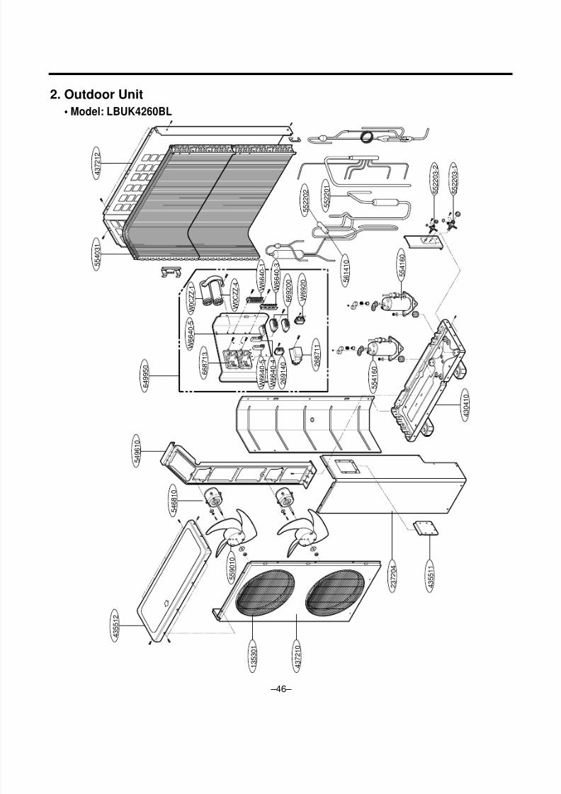
2. Outdoor Unit
• Model: LBUK4260BL
4 3 5 5 1 2
5 4 6 8 1 0
5 5 9 0 1 0
4 3 0 4 1 0
1 3 5 3 0 1
4 3 7 2 1 0
2 3 7 2 0 4
4 3 5 5 1 1
5 5 4 1 6 0
5 5 4 1 6 0
5 4 9 6 1 0
5 5 4 0 3 1
6 4 9 9 5 0
5 5 2 2 0 1
4 3 7 2 1 2
5 5 2 2 0 3 - 2
5 5 2 2 0 3 - 1
W 6 6 4 0 - 5
6 6 8 7 1 3
2 6 8 7 1 1
W 6 6 4 0 - 5
W 6 6 4 0 - 4
W 6 6 4 0 - 1
W 6 6 4 0 - 3
W 6 9 2 0
2 6 9 1 4 0
W 0 C Z Z - 1
W 0 C Z Z - 4
6 6 9 2 0 0 5 6
1 4 1 0
5 5 2 2 0 2

8/6/2019 LG_LBUM7280BL Exploded View
http://slidepdf.com/reader/full/lglbum7280bl-exploded-view 47/55
– 47 –
135301 GRILLE, DISCHARGE 3530AP1225D R
237204 PANEL, SIDE 3720AP1215B R
430410 BASE ASSY, WELD(OUTDOOR) 3041AP2569J R
435511 COVER ASSY, CONTROL(OUTDOOR) 3A01293X R
435512 COVER ASSY, TOP(OUTDOOR) 3550AP1213B R
437210 PANEL ASSY, FRONT SUB 3720AP1212B R
437212 PANEL ASSY, REAR 3720AP1202N R
546810 MOTOP ASSY, OUTDOOR 4681A20013X R
549610 MOUNT, MOTOR 4960A10004A R
552203-1 VALVE, SERVICE 2A00499A R
552203-2 VALVE, SERVICE 2A00393P R
554031 CONDENSER ASSY, BENT 5403A20044P R
554160 COMPRESSOR ASSY, FINAL 5417A90002A R
559010 FAN ASSY, PROPELLER 1A00195B R
649950 CONTROL BOX ASSY, OUTDOOR 4995A20047R R
W6920 RELAY 3A00261C R
669200 RELAY 6920AP3400A R
W6640-1 TERMINAL BLOCK 4G00103A R
W6640-3 TERMINAL BLOCKE 6640A30003A R
668713 PWB(PCB) ASSY, SUB 6871A20052B R
W0CZZ-1 CAPACITOR, DRAWING 0CZZAP3478F R
W0CZZ-4 CAPACITOR, DRAWING 6120AR2194P R
W6640-4 TERMINAL BLOCK 3H00390B R
W6640-5 TERMINAL BLOCK 3H00390A R
269140 TIMER 3A02380B R
268711 PWB(PCB) ASSY, DEICER 6871A20015T R
552202 VALVE, REVERSING 3A02027A R
552201 VALVE, CHECK 3A01020D R
561410 COIL ASSY, REVERSING VALVE 3A02028Y R
LOCATION NO DESCRIPTION Part No. REMARKS
Parts List• Model: LBUK4260BL

8/6/2019 LG_LBUM7280BL Exploded View
http://slidepdf.com/reader/full/lglbum7280bl-exploded-view 48/55
– 48 –
C
S R
4 3 5 5 1 2
5 4 6 8 1 0
6 4 9 9 5 0
5 6 6 0 0 1 - 3
W 6 9 2 0
4 3 0 4 1 0
4 3 7 2 1 2
5 5 2 2 0 3 - 1
5 5 2 2 0
3 - 2
5 5 2 2 0 1
4 3 5 3 0 1
5 5 9 0 1 0
1 3 7 2 1 3
5 6 6 0 0 0
5 6 1 4 1 0
5 5 4 0 3 0 - 1
5 5 4 0 3 0 - 2
5 5 2 2 0 2
4 3
5 5 1 1
4 3 7 2 1 0
5 5 4 1 6 0
W 6 6 4 0 - 1
6
6 8 7 1 3
W 6 6 4 0 - 6
W 0 C Z Z - 3
2 6 8 7 1 1
2. Outdoor Unit
• Model: LBUK4880BL/LBUL6080BL

8/6/2019 LG_LBUM7280BL Exploded View
http://slidepdf.com/reader/full/lglbum7280bl-exploded-view 49/55
435301 GRILLE ASSY, DISCHARGE(OUTDOOR) 3530AP1225D 3530AP1225D R
430410 BASE ASSY, WELD(OUTDOOR) 3041AP2569B 3041AP2569B R
435511 COVER ASSY, CONTROL(OUTDOOR) 3A01293X 3A01293X R
435512 COVER ASSY, TOP(OUTDOOR) 3550AP1213B 3550AP1213B R
437210 PANEL ASSY, FRONT(OUTDOOR) 3720AP1212B 3720AP1212B R
437212 PANEL ASSY, REAR 3720AP1202C 3720AP1202C R
546810 MOTOR ASSY, OUTDOOR 4681A20008P 4681A20008P R
552202 REVERSING VALVE 3A02080A 3A02080A R
552203-1 VALVE, SERVICE 2A00393Q 2A00393Q R
552203-2 VALVE, SERVICE 2A00499C 2A00499C R
554030-1 CONDENSER ASSY, BENDING 5403A20079M 5403A20079M R
554030-2 CONDENSER ASSY, BENDING 5403A20079N 5403A20079N R
` 554160 COMPRESSOR 2520UNDY2AA 5416AP2667F R
559010 FAN ASSY, PROPELLER 1A00195B 1A00195B R
561410 COIL ASSY, REVERSING VALVE 3A02028B 3A02028B R
649950 CONTROL BOX ASSY, OUTDOOR 4995A10010N 4995A10010Z R
W0CZZ-3 CAPACITOR, DRAWING 2A00986D 2A00986D R
268711 PWB ASSY, DEICE 6871A20015N 6871A20015N R
566000 PRESSURE SWITCH 3A01100A 3A01100A R
137213 PANEL, SIDE 3720AP1215B 3720AP1215B R
566001-3 SWITCH, MAGNET 2A01031L 2A01031L R
W6920 RELAY 3A00261C 3A00261C R
668713 PWB(PCB) ASSEMBLY, SUB 6871A30015D 6871A30015D R
W6640-1 TERMINAL BLOCK 4G00103A 4G00103A R
W6640-6 TERMINAL BLOCK 3A00493A 3A00493A R
552201 VALVE, CHECK 3A01020D 3A01020D R
566000 SWITCH, PRESSURE 3A01100A 3A01100A R
– 49 –
LBUK4880BL LBUL6080BL
LOCATION NO DESCRIPTIONPart No.
REMARKS
Parts List• Model: LBUK4880BL/LBUL6080BL
8/6/2019 LG_LBUM7280BL Exploded View
http://slidepdf.com/reader/full/lglbum7280bl-exploded-view 50/55
– 50 –
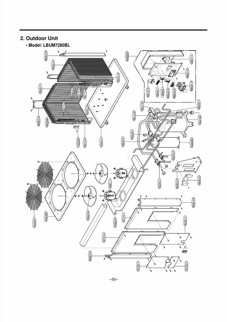
2. Outdoor Unit
• Model: LBUM7280BL
C S R
3 4 9 4 9 0
W 3 5 4 6
5 4 9 6 1 0
4 3
5 3 0 1
4 3 5 5 1 1
1 4 5 2 0 0
4 3 0 4 1 1
W 0 C Z Z - 5
W 6 6 4 0 - 1
W 6 6 4 0 - 6
W 6 6 4 0 - 5
W 6 9 2 0
5 5 2 1 1 5 - 4
5 5 9 0 1 0
3 4 6 8 1 1 - 1
W 4 9 8 1 0 - 3
5 5 2 1 1 5 - 2
5 5 2 1 1 5 - 3
5 5 2 1 1 5 - 1
W 4 9 8 1 0 - 1
W 4 9 8 1 0 - 2
5 5 2 2 0 3 - 1
W 4 9 8 1 0 - 5
4 3 7 2 1 0 - 2
2 3 7 2 0 0 - 1
2 3 7 2 0 0 - 2
W 4 9 8 1 0 - 6
5 5 2 2 0 3 - 2
5 6 6 0 0 0 - 2
5 5 2 1 1 6
5 6 6 0 0 0 - 1
W 4 8 1 0
5 5 2 2 0 1
5 6 1 4 1 0
6 4 9 9
5 0
5 6 6 0 0 1 - 4
2 6 8 7 1 1
6 6 8 7 1 3
5 4 8 4 9 0
5 5 4 1 6 0
4 3 7 2 1 0 - 1
5 5 4 0 3 1 - 1
5 5 4 0 3 1 - 3
5 5 4 0 3 1 - 4
W 4 9 8
1 0 - 4
5 5 4 0 3 1 - 2

8/6/2019 LG_LBUM7280BL Exploded View
http://slidepdf.com/reader/full/lglbum7280bl-exploded-view 51/55
– 51 –
430411 BASE ASSY 3041AP2606V R
554160 COMPRESSOR 5416AP2667F R
548490 ACCUMULATOR 3A02139U R
649950 CONTROL BOX ASSY 4995A20002E R
W6640-6 TERMINAL BLOCK 3A00493A R
W6640-1 TERMINAL BLOCK 4G00103A R
566001-4 SWITCH, MAGIVET 2A01031K R
W0CZZ-5 CAPACITOR, DRAWING 2H00841J R
W6920 RELAY 3A00261C R
W6640-5 TERMINAL BLOCK 3H00390A R
268711 PWB(PCB)ASSY, DEICER 6871A20015T R
668713 PWB(PCB)ASSEMBLY, SUB 6871A30015D R
554031-1 CONDENSER ASSY 5403A20030V R
554031-2 CONDENSER ASSY 5403A20030W R
554031-3 CONDENSER ASSY 5403A20030X R
554031-4 CONDENSER ASSY 5403A20030Y R
145200 LINK SHEET 4520AP4095A R
W49810-1 BRACKET COND 4810AP3697A R
552115-1 TUBE ASSY, (MANIFOLD IN) 5211A30269A R
552115-2 TUBE ASSY, (MANIFOLD IN) 5211A30269B R
552115-3 TUBE ASSY, (MANIFOLD OUT) 5211A20503Q R
552115-4 TUBE ASSY, (MANIFOLD OUT) 5211A20503R R
552116 VALVE, REVERSING 5220AP3777A R
561410 COIL ASYS REVERSING 3A02028B R
552201 CORE VALVE 4A00322A R
566000-1 HIGH PRESSURE SWITCH 6600AG3057A R
566000-2 HIGH PRESSURE SWITCH 3A01100A R
W3546 MESH 2A00191Q R
LOCATION NO. DESCRIPTION Part No. REMARKS
Parts List• Model: LBUM7280BL

8/6/2019 LG_LBUM7280BL Exploded View
http://slidepdf.com/reader/full/lglbum7280bl-exploded-view 52/55
– 52 –
LOCATION NO DESCRIPTION Part No. REMARKS
W49810-2 SUPPORT VALVE 4980AP2621A R
W4810 BRACKET FRONT 4810AP7078A R
552203-1 VALVE SERVICE 2A00469H R
552203-2 VALVE SERVICE 2A00468C R
W49810-3 SUPPORTER REAR 4980AP1265Q R
W49810-4 SUPPORTER REAR 4980AP1265P R
W49810-5 SUPPORTER FRONT 4980AP1264P R
W49810-6 SUPPORTER FRONT 4980AP1263P R
349490 ORIFICE ASSY 4948AP1242R R
549610 MOUNT MOTOR ASSY 4961A10002A R
346811-1 MOTOR 4680AP2610B R
559010 FAN ASSY 0A00026B R
435301 GRILLE COVER 4948AP1242R R
437210-1 PANEL ASSY FRONT 3721AP2913P R
437210-2 PANEL ASSY FRONT 3721AP2913Q R
435511 COVER ASSY CONTROL 3551AP7047Z R
237200-1 PANEL INSTALL-U 3720AP3810P R237200-2 BRACKET INSTALL-L 4810AP3814P R
Parts List• Model: LBUM7280BL

8/6/2019 LG_LBUM7280BL Exploded View
http://slidepdf.com/reader/full/lglbum7280bl-exploded-view 53/55
Memo
– 53 –

8/6/2019 LG_LBUM7280BL Exploded View
http://slidepdf.com/reader/full/lglbum7280bl-exploded-view 54/55
Memo
– 54 –

8/6/2019 LG_LBUM7280BL Exploded View
http://slidepdf.com/reader/full/lglbum7280bl-exploded-view 55/55