lg - information technology | drexel universityjm328/ae391/a4/lennoxrtu.pdf · lg l series®...
TRANSCRIPT
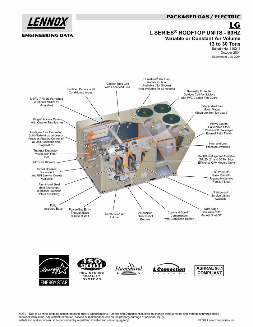
PACKAGED �L" SERIESPACKAGED GAS / ELECTRIC
ENGINEERING DATA
Aluminized SteelHeat Exchanger
(Optional StainlessSteel Available)
Dual StageGas Valve with
Manual Shut−Off
Power/Gas EntryThrough Baseor Side of Unit
Intelligent Unit ControllerSolid−State MicroprocessorProvides Flexible Control of
all Unit Functions andDiagnostics
Thermally ProtectedOutdoor Coil Fan Motors
with PVC Coated Fan Guard
Belt Drive Blowers
Humiditrol® Hot GasReheat Option
Available (Not Shown)(Not available for all models)
MERV 7 Filters Furnished(Optional MERV 11
Available)
Heavy GaugeGalvanized Steel
Panels with Two−layerEnamel Paint Finish
AluminizedSteel Inshot
Burners
Full PerimeterBase Rail with
Rigging Holes andFork Lift Slots
R−410A Refrigerant Available(15, 20, 21 and 30 Ton HighEfficiency CAV Models Only)
Hinged Access Panelswith Quarter Turn latches
Insulated Panels in allConditioned Areas
Copper Tube Coilwith Enhanced Fins
Circuit Breaker,Disconnect
and GFI Service OutletsAvailable
Combustion AirInducer
ASHRAE 90.1COMPLIANT
Thermal ExpansionValves with Filter
Drier
FullyInsulated Base
High and LowPressure Switches
Independent FanMotor Mount
(Separate from fan guard)
Copeland Scroll�Compressors
with Crankcase Heater
RefrigerantService Valves
Available
LGL SERIES® ROOFTOP UNITS − 60HZ
Variable or Constant Air Volume13 to 30 Tons
Bulletin No. 210318
October 2004
Supersedes July 2004
NOTE − Due to Lennox’ ongoing committment to quality, Specifications, Ratings and Dimensions subject to change without notice and without incurring liability.Improper installation, adjustment, alteration, service or maintenance can cause property damage or personal injury.Installation and service must be performed by a qualified installer and servicing agency. �2004 Lennox Industries Inc.
L Series Packaged Gas/Electric − 13 to 30 Tons / Page 2
TABLE OF CONTENTS
Application Guide − Controls Pages 85−87. . . . . . . . . . . . . . . . . . . . . . . . . . . . . . . . . . . . . . . . . . . . . . . . . . . . . . . . . . . Accessory Air Resistance Pages 41−43. . . . . . . . . . . . . . . . . . . . . . . . . . . . . . . . . . . . . . . . . . . . . . . . . . . . . . . . . . . . . Blower Data Pages 38−40. . . . . . . . . . . . . . . . . . . . . . . . . . . . . . . . . . . . . . . . . . . . . . . . . . . . . . . . . . . . . . . . . . . . . . . . . Control Systems Pages 53−61. . . . . . . . . . . . . . . . . . . . . . . . . . . . . . . . . . . . . . . . . . . . . . . . . . . . . . . . . . . . . . . . . . . . . Cooling Ratings Pages 24−29. . . . . . . . . . . . . . . . . . . . . . . . . . . . . . . . . . . . . . . . . . . . . . . . . . . . . . . . . . . . . . . . . . . . . Dimensions Pages 64−75. . . . . . . . . . . . . . . . . . . . . . . . . . . . . . . . . . . . . . . . . . . . . . . . . . . . . . . . . . . . . . . . . . . . . . . . . Electrical Data Pages 47−51. . . . . . . . . . . . . . . . . . . . . . . . . . . . . . . . . . . . . . . . . . . . . . . . . . . . . . . . . . . . . . . . . . . . . . . Features and Benefits Pages 3−7. . . . . . . . . . . . . . . . . . . . . . . . . . . . . . . . . . . . . . . . . . . . . . . . . . . . . . . . . . . . . . . . . . Guide Specifications Pages 76−84. . . . . . . . . . . . . . . . . . . . . . . . . . . . . . . . . . . . . . . . . . . . . . . . . . . . . . . . . . . . . . . . . High Altitude Information Page 37. . . . . . . . . . . . . . . . . . . . . . . . . . . . . . . . . . . . . . . . . . . . . . . . . . . . . . . . . . . . . . . . . . Humiditrol® Condenser Reheat Option Pages 9−10. . . . . . . . . . . . . . . . . . . . . . . . . . . . . . . . . . . . . . . . . . . . . . . . . . . Humiditrol® Condenser Reheat Ratings Pages 35−37. . . . . . . . . . . . . . . . . . . . . . . . . . . . . . . . . . . . . . . . . . . . . . . . . Installation Clearances Page −51−52. . . . . . . . . . . . . . . . . . . . . . . . . . . . . . . . . . . . . . . . . . . . . . . . . . . . . . . . . . . . . . . Model Number Identification Page 2. . . . . . . . . . . . . . . . . . . . . . . . . . . . . . . . . . . . . . . . . . . . . . . . . . . . . . . . . . . . . . . . Optional Accessories Pages 8−13. . . . . . . . . . . . . . . . . . . . . . . . . . . . . . . . . . . . . . . . . . . . . . . . . . . . . . . . . . . . . . . . . . Optional Disconnect Switch Requirements Page 46. . . . . . . . . . . . . . . . . . . . . . . . . . . . . . . . . . . . . . . . . . . . . . . . . . Specifications Pages 14−23. . . . . . . . . . . . . . . . . . . . . . . . . . . . . . . . . . . . . . . . . . . . . . . . . . . . . . . . . . . . . . . . . . . . . . . Sound Data Page 51. . . . . . . . . . . . . . . . . . . . . . . . . . . . . . . . . . . . . . . . . . . . . . . . . . . . . . . . . . . . . . . . . . . . . . . . . . . . . Weight Data Pages 62−63. . . . . . . . . . . . . . . . . . . . . . . . . . . . . . . . . . . . . . . . . . . . . . . . . . . . . . . . . . . . . . . . . . . . . . . . .
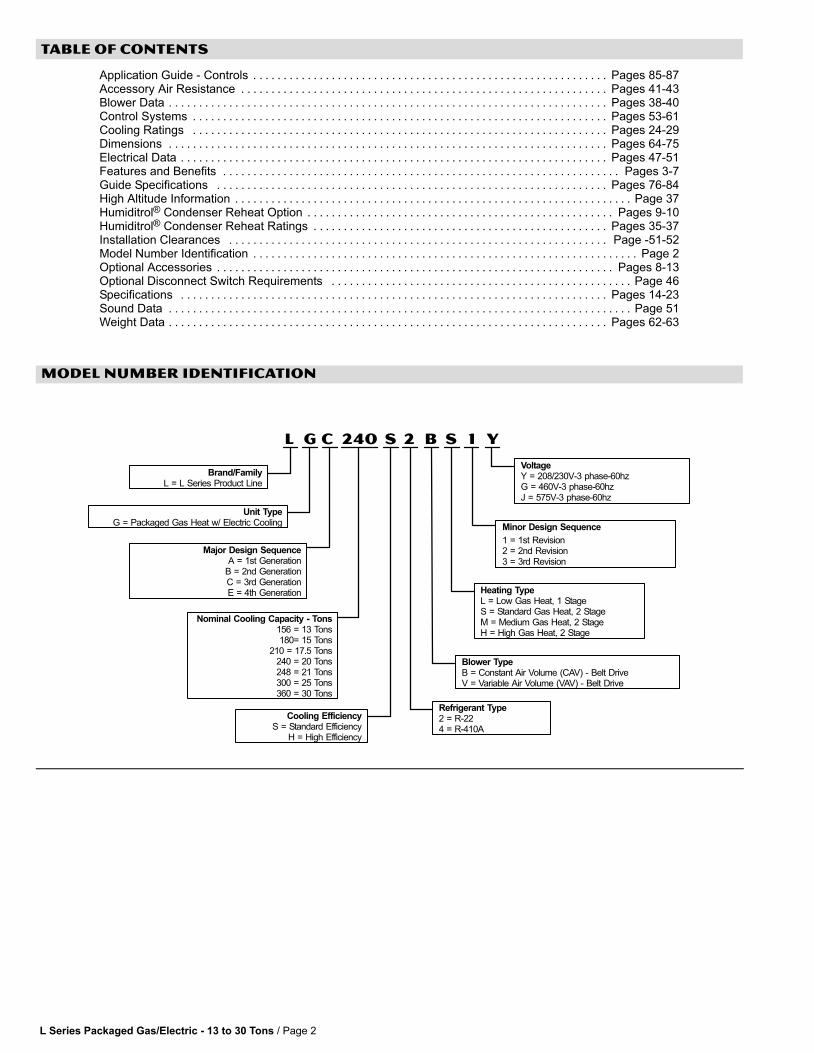
MODEL NUMBER IDENTIFICATION
L G C Y1240 S S2 B
Major Design SequenceA = 1st Generation
B = 2nd GenerationC = 3rd GenerationE = 4th Generation
Brand/FamilyL = L Series Product Line
Unit TypeG = Packaged Gas Heat w/ Electric Cooling
Nominal Cooling Capacity − Tons156 = 13 Tons180= 15 Tons
210 = 17.5 Tons240 = 20 Tons248 = 21 Tons300 = 25 Tons360 = 30 Tons
Cooling EfficiencyS = Standard Efficiency
H = High Efficiency
Minor Design Sequence
1 = 1st Revision2 = 2nd Revision3 = 3rd Revision
VoltageY = 208/230V-3 phase-60hzG = 460V-3 phase-60hzJ = 575V-3 phase-60hz
Heating TypeL = Low Gas Heat, 1 StageS = Standard Gas Heat, 2 StageM = Medium Gas Heat, 2 StageH = High Gas Heat, 2 Stage
Refrigerant Type2 = R−224 = R−410A
Blower TypeB = Constant Air Volume (CAV) − Belt DriveV = Variable Air Volume (VAV) − Belt Drive
L Series Packaged Gas/Electric − 13 to 30 Tons / Page 3
FEATURES AND BENEFITS
CERTIFICATIONSETL and CSA listed.Heating efficiency ratings verified byCSA.Components bonded for grounding tomeet safety standards for servicingrequired by UL, CSA and National andCanadian Electrical Codes.156 thru 248 models are certified inaccordance with the ULE certificationprogram, which is based on ARIStandard 340/360-2000.300 and 360 models are tested atconditions included in ARI Standard340/360−2000.ISO 9001 Registered ManufacturingQuality System.ENERGY STAR® certified units aredesigned to use less energy, help savemoney on utility bills, and help protectthe environment.
WARRANTYLimited ten years aluminized heatexchanger, limited fifteen years optionalstainless steel heat exchanger.Limited five years on compressors.Limited three years on IntegratedModular Control.Limited one year all other coveredcomponents.
COOLING SYSTEMDesigned to maximize sensible andlatent cooling performance at designconditions.Two efficiency levels provide flexibility.System can operate from 0°F to 125°Fwithout any additional controls.
CompressorsResiliently mounted on rubbergrommets for quiet operation.Copeland Scroll� compressors on allmodels for high performance, reliabilityand quiet operation.
Compressor Crankcase HeatersProtects against refrigerant migrationthat can occur during low ambientoperation.
Thermal Expansion ValvesAssures optimal performancethroughout the application range.Removable element head.
Filter/DriersHigh capacity filter/driers protect thesystem from dirt and moisture.
High Pressure SwitchesProtects the compressor from overloadconditions such as dirty condensercoils, blocked refrigerant flow, or loss ofoutdoor fan operation. Automatic reset
Low Pressure SwitchesProtects the compressor from lowpressure conditions such as lowrefrigerant charge, or low/no air flow.Automatic reset
Freezestats
Protects the evaporator coil fromdamaging ice build−up due to conditionssuch as low/no air flow, or low/norefrigerant charge.
Coil Construction
Copper tube construction, enhancedrippled−edge aluminum fins, flaredshoulder tubing connections, silversoldered construction for improved heattransfer. Factory leak tested.
Evaporator Coil
Cross row circuiting with rifled coppertubing optimizes both sensible andlatent cooling capacity. Low fin per inchcount minimizes air pressure drop.Constant air volume (CAV) models haveface−split evaporator coils. Variable airvolume (VAV) models have row−splitevaporator coils designed to keepcondensate water off of an inactive partof the coil so the condensate will notre−enter the air stream.
Condenser Coil
Angled, slab design helps protect coilfrom possible contact or hail damage.
Condensate Drain Pan
Drain connection extends outside unit.Painted, galvanized pan with positiveslope.Stainless steel drain pan available as afactory installed option.
Outdoor Coil Fan Motors
Thermal overload protected, totallyenclosed, permanently lubricated ballbearings, shaft up, wire basket mount.
Outdoor Coil Fan
PVC coated fan guard furnished.
Refrigerant Choice
LGC180H, LGA240H, LGA248H, andLGA360H models can be ordered withR−22 (CAV and VAV models) or R−410A(CAV models only) refrigerant systems.
REQUIRED SELECTIONSCooling CapacitySpecify the nominal cooling capacity ofthe unit
Cooling EfficiencySpecify either standard or highefficiency.
Refrigerant Choice(LGC180H, LGA240H, LGA248H, andLGA360H Models Only)Specify R−22 (CAV and VAV models) orR−410A (CAV models only) refrigerant.
OPTIONS / ACCESSORIESFactory Installed
Discharge Air Temperature SensorSensor sends information to the IMC tocycle up to 4 stages of heating or coolingto maintain the discharge air setpointsfor heating or cooling. Optional for CAVunits (single zone or bypass zoningcontrol). Automatically furnished with allVariable Air Volume (VAV) units. Sensoris shipped with the unit for remote fieldinstallation in the supply duct.
Service ValvesFully serviceable brass valves installedin discharge & liquid lines. Not for usewith Humiditrol equipped units.
Four Stage ControlAdd−on board that enables the unit tooperate four stages of cooling and fourstages of gas heat when controlled by a4−stage thermostat or aftermarket DDCcontrol system.For 248H, 300H, 360H models only.
Fresh Air TemperingProvides heating and cooling as neededto maintain the supply air temperaturewithin a comfort range, regardless of thethermostat demand. Sensor ships withunit but must be field installed in thesupply air duct. Requires change to IMC(ECTO) parameter in the field to activatethis mode of operation.
Stainless Steel Condensate Drain PanFactory installed
Factory or Field Installed
Condensate Drain TrapField installed only, may be factoryenclosed to ship with unit. Available incopper or PVC.
L Series Packaged Gas/Electric − 13 to 30 Tons / Page 4
FEATURES AND BENEFITS
HEATING SYSTEM
Aluminized steel inshot burners, directspark ignition, electronic flame sensor,combustion air inducer, redundantautomatic single or dual stage gas valvewith manual shut-off.
Heat Exchanger
Tubular construction, aluminized steel,life cycle tested.Stainless Steel Heat Exchanger isrequired if mixed air temperature is lessthan 45°F.
Fan & Limit Controls
Factory installed with fixed temperaturesetting.Heat limit controls protect againstoverheating.
Safety Switches
Flame roll−out switches, flame sensorsand combustion air inducer provingswitches protect system operation.All safety switches are monitored by theIMC unit controller and diagnostic errorsare reported and recorded.
REQUIRED SELECTIONS
Gas Input − Order one:
169,000 Btuh Low Heat Gas Input(LGC156, LGC180 and LGC210models only).169,000 / 260,000 Btuh low/high fire −Standard Heat Gas Input.234,000 / 360,000 Btuh low/high fire −Medium Gas Heat Input.312,000 / 480,000 Btuh low/high fire −High Gas Heat Input (Not available forLGC156).
OPTIONS / ACCESSORIESFactory Installed
Discharge Air Temperature SensorSensor sends information to the IMC tocycle up to 4 stages of heating or coolingto maintain the discharge air setpointsfor heating or cooling. Optional for CAVunits (single zone or bypass zoningcontrol). Automatically furnished with allVariable Air Volume (VAV) units. Sensoris shipped with the unit for remote fieldinstallation in the supply duct.
Stainless Steel Heat ExchangerRequired if mixed air temperature isbelow 45°F.
Four Stage Control − Add−on board thatenables the unit to operate four stages ofcooling and four stages of gas heat whencontrolled by a 4−stage thermostat oraftermarket DDC control system.For 248H, 300H, 360H models only.
Factory or Field Installed
Fresh Air TemperingProvides heating and cooling as neededto maintain the supply air temperaturewithin a comfort range, regardless of thethermostat demand. Sensor ships withunit but must be field installed in thesupply air duct. Requires change to IMC(ECTO) parameter in the field to activatethis mode of operation.
Field Installed
Combustion Air Intake ExtensionsRecommended for use with existing flueextension kits in areas where high snowdrifts can block intake air.
LPG/Propane KitsConversion kit to field change over unitsfrom Natural Gas to LPG/Propane.
Vertical Vent Extension KitExhausts flue gases vertically aboveunit.
BLOWERA wide selection of supply air bloweroptions are available to meet a variety ofair flow requirements.
MotorOverload protected, equipped with ballbearings.Belt drive motors are offered in severaldifferent sizes to maximize airperformance.
Motor EfficiencySpecify standard or high.
Supply Air BlowerForward curved blades, blower wheel isstatically and dynamically balanced.Belt drive motors with adjustable pulleyfor speed change on CAV units.Blower assembly slides out of unit forservicing.Grease fittings furnished.
REQUIRED SELECTIONSSupply Air BlowerSpecify Constant Air Volume (CAV) orVariable Air Volume (VAV). OrderStandard or High Efficiency Blowermotor (See Blower Data Table forspecifications).NOTE − 575V VAV models are onlyavailable with high efficiency blowermotors.Order one drive kit, see Drive KitSpecifications Table.
OPTIONS / ACCESSORIESFactory Installed
Supply Static TransducerTransducer sends information to the IMCto control VFD blower speed. Optional forCAV units (single zone or bypass zoningcontrol). Automatically furnished with allVAV units. Transducer is shipped with theunit for remote field installation in thesupply duct.
Supply VFD Blower Bypass ControlAllows variable air volume (VAV) unit tooperate as a constant air volume (CAV)unit in case of variable frequency drive(VFD) failure.
Field Installed
Supply Static Limit SwitchField installed manual reset switch forsupply static high pressure limit.Prevents exceeding pressure limit insupply air duct. Optional Mounting Kitincludes tubing and adaptors.

L Series Packaged Gas/Electric − 13 to 30 Tons / Page 5
FEATURES AND BENEFITS
CABINETConstructionHeavy−gauge steel panels and fullperimeter heavy−gauge galvanizedsteel base rail provides structuralintegrity for transportation, handling,and installation.Base rails have rigging holes. Threesides of the base rail have fork slots.Raised edges around duct and powerentry openings in the bottom of the unitprovide additional protection againstwater entering the building.
Air−Flow ChoiceUnits are available in down−flow(vertical) or horizontal return air flowconfiguration.Horizontal air flow requires HorizontalRoof Curb.Horizontal Return Air Panel Kit is alsorequired if converting a down−flowconfigured unit to horizontal air flow.
Power and Gas EntryElectrical and gas lines can be broughtthrough the unit base or throughhorizontal access knock−outs.
Exterior PanelsConstructed of heavy−gauge,galvanized steel with a two−layerenamel paint finish.
InsulationAll panels adjacent to conditioned air arefully insulated with non−hygroscopicfiberglass insulation.Unit base is fully insulated. Theinsulation also serves as an air seal tothe roof curb, eliminating the need toadd a seal during installation.
Access PanelsHinged access panels are provided for 2compressor/controls/heating areas,blower access and air filter/economizeraccess.All panels have seals and quarter−turnlatching handles to provide a tight airand water seal.
REQUIRED SELECTIONS
Air Flow Configuration
Specify horizontal or down−flow.
OPTIONS / ACCESSORIES
Factory Installed
Corrosion Protection
Phenolic epoxy coating, applied tocondenser coils (with painted basesection) and evaporator coils (withpainted base and painted blowerhousings), factory applied to eithersection or both sections.
Field Installed
Coil Guards
Painted, galvanized steel wire guards toprotect outdoor coil. Not used with HailGuards.
Grille Guards
Protects the space between outdoorcoils and main cabinet.
Hail Guards
Constructed of heavy gauge steel,painted to match cabinet, helps protectoutdoor coils from hail damage. Notused with Coil Guards.
Horizontal Return Air Panel Kit
Required for horizontal applications withHorizontal Roof Curb, contains panelwith return air opening for fieldreplacement of existing unit panel andpanel to cover bottom return air openingin unit, see dimension drawings.
AIR FILTERS
Disposable 2 inch (51 mm) pleatedMERV 7 filters (Minimum EfficiencyReporting Value based on ASHRAE52.2).
OPTIONS / ACCESSORIES
Factory or Field Installed
MERV 11 Filters
Disposable 2 inch pleated MERV 11filters (Minimum Efficiency ReportingValue based on ASHRAE 52.2).
L Series Packaged Gas/Electric − 13 to 30 Tons / Page 6
FEATURES AND BENEFITS
CONTROLS
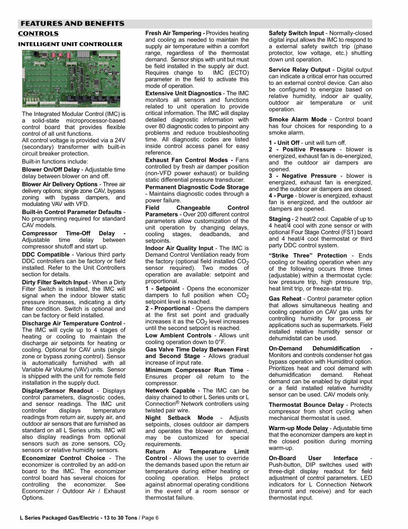
Intelligent Unit Controller
The Integrated Modular Control (IMC) isa solid−state microprocessor−basedcontrol board that provides flexiblecontrol of all unit functions.All control voltage is provided via a 24V(secondary) transformer with built−incircuit breaker protection.
Built-in functions include:
Blower On/Off Delay − Adjustable timedelay between blower on and off.
Blower Air Delivery Options − Three airdelivery options; single zone CAV, bypasszoning with bypass dampers, andmodulating VAV with VFD.
Built-in Control Parameter Defaults −No programming required for standardCAV models.
Compressor Time−Off Delay −Adjustable time delay betweencompressor shutoff and start up.
DDC Compatible − Various third partyDDC controllers can be factory or fieldinstalled. Refer to the Unit Controllerssection for details.
Dirty Filter Switch Input − When a DirtyFilter Switch is installed, the IMC willsignal when the indoor blower staticpressure increases, indicating a dirtyfilter condition. Switch is optional andcan be factory or field installed.
Discharge Air Temperature Control −The IMC will cycle up to 4 stages ofheating or cooling to maintain thedischarge air setpoints for heating orcooling. Optional for CAV units (singlezone or bypass zoning control). Sensoris automatically furnished with allVariable Air Volume (VAV) units. Sensoris shipped with the unit for remote fieldinstallation in the supply duct.
Display/Sensor Readout − Displayscontrol parameters, diagnostic codes,and sensor readings. The IMC unitcontroller displays temperaturereadings from return air, supply air, andoutdoor air sensors that are furnished asstandard on all L Series units. IMC willalso display readings from optionalsensors such as zone sensors, CO2sensors or relative humidity sensors.
Economizer Control Choice − Theeconomizer is controlled by an add−onboard to the IMC. The economizercontrol board has several choices forcontrolling the economizer. SeeEconomizer / Outdoor Air / ExhaustOptions.
Fresh Air Tempering − Provides heatingand cooling as needed to maintain thesupply air temperature within a comfortrange, regardless of the thermostatdemand. Sensor ships with unit but mustbe field installed in the supply air duct.Requires change to IMC (ECTO)parameter in the field to activate thismode of operation.
Extensive Unit Diagnostics − The IMCmonitors all sensors and functionsrelated to unit operation to providecritical information. The IMC will displaydetailed diagnostic information withover 80 diagnostic codes to pinpoint anyproblems and reduce troubleshootingtime. All diagnostic codes are listedinside control access panel for easyreference.
Exhaust Fan Control Modes − Fanscontrolled by fresh air damper position(non−VFD power exhaust) or buildingstatic differential pressure transducer.
Permanent Diagnostic Code Storage− Maintains diagnostic codes through apower failure.
Field Changeable ControlParameters − Over 200 different controlparameters allow customization of theunit operation by changing delays,cooling stages, deadbands, andsetpoints.
Indoor Air Quality Input − The IMC isDemand Control Ventilation ready fromthe factory (optional field installed CO2sensor required). Two modes ofoperation are available: setpoint andproportional.
1 − Setpoint − Opens the economizerdampers to full position when CO2setpoint level is reached.2 − Proportional − Opens the dampersat the first set point and graduallyincreases it as the CO2 level increasesuntil the second setpoint is reached.
Low Ambient Controls − Allows unitcooling operation down to 0°F.
Gas Valve Time Delay Between Firstand Second Stage − Allows gradualincrease of input rate.
Minimum Compressor Run Time −Ensures proper oil return to thecompressor.
Network Capable − The IMC can bedaisy chained to other L Series units or LConnection® Network controllers usingtwisted pair wire.
Night Setback Mode − Adjustssetpoints, closes outdoor air dampersand operates the blower on demand,may be customized for specialrequirements.
Return Air Temperature LimitControl − Allows the user to overridethe demands based upon the return airtemperature during either heating orcooling operation. Helps protectagainst abnormal operating conditionsin the event of a room sensor orthermostat failure.
Safety Switch Input − Normally−closeddigital input allows the IMC to respond toa external safety switch trip (phaseprotector, low voltage, etc.) shuttingdown unit operation.
Service Relay Output − Digital outputcan indicate a critical error has occurredto an external control device. Can alsobe configured to energize based onrelative humidity, indoor air quality,outdoor air temperature or unitoperation.
Smoke Alarm Mode − Control boardhas four choices for responding to asmoke alarm.
1 − Unit Off − unit will turn off.2 − Positive Pressure − blower isenergized, exhaust fan is de−energized,and the outdoor air dampers areopened.3 − Negative Pressure − blower isenergized, exhaust fan is energized,and the outdoor air dampers are closed.4 − Purge − blower is energized, exhaustfan is energized, and the outdoor airdampers are opened.
Staging − 2 heat/2 cool. Capable of up to4 heat/4 cool with zone sensor or withoptional Four Stage Control (FS1) boardand 4 heat/4 cool thermostat or thirdparty DDC control system.
�Strike Three" Protection − Endscooling or heating operation when anyof the following occurs three times(adjustable) within a thermostat cycle:low pressure trip, high pressure trip,heat limit trip, or freeze−stat trip.
Gas Reheat − Control parameter optionthat allows simultaneous heating andcooling operation on CAV gas units forcontrolling humidity for process airapplications such as supermarkets. Fieldinstalled relative humidity sensor ordehumidistat can be used.
On−Demand Dehumidification −Monitors and controls condenser hot gasbypass operation with Humiditrol option.Prioritizes heat and cool demand withdehumidification demand. Reheatdemand can be enabled by digital inputor a field installed relative humiditysensor can be used. CAV models only.
Thermostat Bounce Delay − Protectscompressor from short cycling whenmechanical thermostat is used.
Warm-up Mode Delay − Adjustable timethat the economizer dampers are kept inthe closed position during morningwarm−up.
On−Board User Interface −Push−button, DIP switches used withthree−digit display readout for fieldadjustment of control parameters. LEDindicators for L Connection Network(transmit and receive) and for eachthermostat input.

L Series Packaged Gas/Electric − 13 to 30 Tons / Page 7
FEATURES AND BENEFITS
CONTROLS − CONTINUEDPC Interface − PC with optional UnitController software may be used to fieldor remotely adjust parameters, readalarms, or display unit status.VAV Control − Supports variable airvolume (VAV) units with variablefrequency drive or constant air volumeunits with bypass zoning control system.Constant air volume bypass zoningcontrol units require add−on controlboard.
Zone Sensor Operation − Controlszone temperature with up to 4 stages ofheating or cooling with optional zonesensor. Four Stage Control (FS1) Boardis not required.
OPTIONS / ACCESSORIESFactory Installed
Four Stage ControlProvides additional 24VAC thermostatinputs for 4 heat/4 cool thermostats andaftermarket DDC controls. Factoryinstalled.
Factory or Field Installed
Blower Proving SwitchMonitors blower operation, shuts downunit if blower fails. Factory installed.
Dirty Filter SwitchSenses static pressure increaseindicating dirty filter condition.
Indoor Air Quality (CO2) SensorMonitors CO2 levels, reports to IMC boardwhich adjusts economizer dampers asneeded.
Smoke DetectorPhotoelectric type, installed in supply airsection or return air section or bothsections
Commercial Control Systems
L Connection® NetworkControl system to complement the IMCin single zone applications. Optionsinclude local interface, software for localor remote communication, andhardware for networking other controlfunctions.See pages 53 − 55.Sectra� Commercial Zoning SystemControl system to complement the IMCin VFD, bypass zoning applications andsingle zone control. Options includelocal interface, software for local orremote communication, and hardwarefor networking other control functions.See Pages 56 − 58.
Aftermarket DDCSee Pages 59−60.
ThermostatsControl system and thermostat options.Aftermarket unit controller options.See Page 61.
Field Installed
Humidity Sensor Kit, RemoteMountedHumidity sensor required with factoryinstalled Humiditrol Option.
ELECTRICAL
REQUIRED SELECTIONS
Voltage Choice
Specify 208/23V, 460V or 575V3−phase−60hz when ordering base unit.
OPTIONS / ACCESSORIES
Factory Installed
Circuit Breakers up to 250 Amp
HACR circuit breaker without powerdistribution lugs. Accessible fromoutside of unit, spring−loadedweatherproof cover furnished. Mainpower to the unit is field connected to thecircuit breaker which allows all power tobe shutoff for service. Circuit breaker issized to the unit maximum overcurrentprotection (MOCP) size.
Field Installed
Disconnect Switch up to 250 Amp
Accessible from outside of unit, springloaded weatherproof cover furnished.Main power to the unit is field connectedto the disconnect which allows all powerto be shut off for service. See OptionalDisconnect Switch Requirements table,Page 46 for field installed disconnectswitches.
GFI Service Outlets (2)
115v ground fault circuit interrupter(GFCI) type, field wired or unit powered.
SERVICEABILITYDesigned to streamline generalmaintenance and decreasetroubleshooting time.
DiagnosticsIMC diagnostic codes pinpointproblems, minimizing troubleshootingtime.
Marked & Color−Coded WiringAll electrical wiring is color−coded andmarked to identify which components itis connecting.
Electrical PlugsPositive connection electrical plugs areused to connect common accessoriesor maintenance parts for easy removalor installation.
Tool−less, Hinged Access PanelsLarge access panels are hinged andhave quarter−turn, latching handles forquick and easy access to maintenanceareas.Filter access panels are hinged for easyaccess to the filters.
Blower AccessBlower assembly slides out of the unitfor easy access.
Coil CleaningSlab condenser coils allow easiercleaning.
Standard ComponentsA large number of commonmaintenance parts are standardthroughout the entire range of sizes(3−30 tons), reducing the need to carry alot of different parts to the job or ininventory.
Compressor CompartmentCompressors are located near theperimeter of the unit for easier access.Compressors are isolated from thecondenser air flow allowing systemoperation checks to be done withoutchanging the air flow across the outdoorcoils.
Thermal Expansion ValvesThermal expansion valves are locatednear the perimeter of the unit for easieraccess.Removable element head allowschange out of element and bulb withoutremoving the TXV.
Service Valves (optional)Optional factory installed liquid anddischarge service valves allowrefrigerant to be isolated to the high sidefor service work on the low side of therefrigeration system.

L Series Packaged Gas/Electric − 13 to 30 Tons / Page 8
OPTIONS / ACCESSORIES
ECONOMIZER/OUTDOOR AIR/EXHAUSTFactory or Field Installed
Economizer − Parallel gear driven actionrecirculated air and outdoor air dampers,plug-in connections to unit, nylonbearings, neoprene seals, 24 volt fullymodulating spring return motor,adjustable minimum damper position,damper assembly slides in unit, outdoorair hood must be ordered separately,optional down-flow barometric reliefdampers available, choice of economizercontrols. The IMC add−on board foreconomizer control is included with theeconomizer. Control board has fivechoices for controlling the economizer(DIP switch selections).
1 − Differential Sensible Control −Factory setting. Uses the outdoor airand return air sensors that arefurnished with the unit. The IMCcompares the outdoor air and return airand using setpoints, enables theeconomizer when the outdoor airtemperature is below the configuredsetpoint and cooler than return air.NOTE − Differential Sensible Controlcan be configured in the field to provideOffset Differential Sensible Control orSingle Sensible Control.In Offset Differential Sensible Controlmode, the economizer is enabled if thetemperature differential (offset)between outdoor air and return airreaches the configured setpoint.In Single Sensible Control mode, theeconomizer is enabled when outdoorair temperature falls b2 − Single Sensible Control −Differential Sensible Control abovecan be configured to Single SensibleControl. The IMC compares theoutdoor air sensor temperature to thesetpoint and enables the economizerwhen the outdoor air is cooler than thesetpoint.3 − Global Control − The IMCcommunicates with a DDC system withone global sensor (enthalpy or sensible)to determine whether outside air issuitable for free cooling on all unitsconnected to the control system. Sensormust be field provided.4 − Single Enthalpy Control − Outdoorair enthalpy sensor enableseconomizer if the outdoor enthalpy isless than the setpoint of the board.Factory installed.5 − Differential Enthalpy Control −Two solid-state enthalpy sensors allowthe economizer control board to selectbetween outdoor air or return air,whichever has lower enthalpy. Factoryinstalled.
Outdoor Air Dampers (Manual orMotorized) − Linked mechanicaldampers, 0 to 25% (fixed) outdoor airadjustable, installs in unit, outdoor airhood must be ordered separately.Motorized model features fully modulatingspring return damper motor with plug−inconnection. Manual model features a slidedamper.Minimum mixed air temperature inheating mode 30°F. Maximum mixed airtemperature in cooling mode: 90°F.
Outdoor Air Hood − Required withLAREMD Economizer, LAOAD andLAOADM Outdoor Air DamperSections, cleanable aluminum meshfresh air filters furnished.
Down−Flow Barometric ReliefDampers − Allows relief of excess air,aluminum blade dampers prevent blowback and outdoor air infiltration duringoff cycle, bird screen furnished.Dampers are required with StandardStatic Power Exhaust Fans. Down−FlowBarometric Relief Damper Hood isavailable and must be ordered extra.
Field Installed
Down−Flow Barometric ReliefDamper Hood − Field installed only. Usewith Barometric Relief Dampers.
Horizontal Barometric ReliefDampers − Aluminum blade dampersprevent blow back and outdoor airinfiltration during off cycle, field installedin return air duct, bird screen furnished.
Factory or Field Installed
Standard Static Power Exhaust Fans− LAPEF18/24 models have two, 1/3 hpmotors with 20 in., five bladepropeller−type fans with a total powerinput of 750 Watts and a total air volumeof 8630 cfm at 0 in. w.g.LAPEF30/36 models have three, 1/3 hpmotors with 20 in., five bladepropeller−type fans with a total powerinput of 1125 Watts and a total airvolume of 12,800 cfm at 0 in. w.g.Motor is inherently protected andenclosed for maximum protection fromweather, dust and corrosion. Installsinternal to unit for down-flowapplications only with economizeroption, provides exhaust air pressurerelief, interlocked to run when return airdampers are closed and supply airblower is operating, fan runs whenoutdoor air dampers are 50% open(adjustable), motor is overloadprotected, steel cabinet and hoodpainted to match unit, requires optionalDown-flow Economizer BarometricRelief Dampers. See Standard Static Power ExhaustBlower Tables.
High Static Power Exhaust Fans(248H/300H/360H Models Only −Choice of 50% (two, 2 hp motors) or100% (three, 2 hp motors)centrifugal−type power exhaust.Overload and sub−fuse protected,equipped with ball bearings. Forwardcurved blades, blower wheel is staticallyand dynamically balanced.Constant volume high static powerexhaust fans have adjustable pulleys forspeed adjustments and are controlledby damper position.
Variable air volume units (with variablefrequency drive) have 100% capacityand can be ordered with an optionalVFD bypass. Fans feature solid−stateanalog pressure transducer controlwhich senses differential pressurebetween conditioned space and outdoorair to regulate fan speed. See PowerExhaust Blower TablesSee High Static Power Exhaust BlowerTables.NOTE − High Static Power Exhaust isfield installed but must be ordered at thesame time as the rooftop unit so the unitcan be factory configured for this option.
Power Exhaust Control Options:
Damper Position ControlIMC controls exhaust fan based oneconomizer damper position. ForStandard or High Static PowerExhaust (without VFD) Fans only.
Differential Pressure TransducerDifferential pressure transducercompares atmospheric pressure toconditioned space static pressure forcontrolling exhaust fan. Transducer isshipped with the unit for remote fieldinstallation. For High Static PowerExhaust (with VFD) fans only.
CEILING DIFFUSERS
Field Installed
Ceiling Diffusers − Aluminum grilles,large center grille, insulated diffuser boxwith flanges, hanging rings furnished,interior transition (even air flow),internally sealed (preventsrecirculation), adapts to T-bar ceilinggrids or plaster ceilings.
Transitions (Supply and Return) −Used with diffusers, installs in roof curb,galvanized steel construction, flangesfurnished for duct connection todiffusers, fully insulated.
ROOF CURBS
Field Installed
Nailer strip furnished, mates to unit,shipped knocked down.Standard Down−Flow − US NationalRoofing Contractors Approved,available in 14 inch and 24 inch heightsHorizontal − Converts unit fromdown-flow to horizontal (side) air flow,return air is on unit, supply air is on curb,see dimension drawings. Curbs forrooftop applications meet NationalRoofing Code requirements. RequiresHorizontal Return Air Panel. Available in26 inch, 30 inch, 37 inch and 41 inchheights. Optional Insulation Kit isavailable to help prevent sweating.
Cliplock 1000 Full PerimeterDown−Flow − Available in 14 inch, 18inch and 24 inch heights.
L Series Packaged Gas/Electric − 13 to 30 Tons / Page 9
OPTIONS
HUMIDITROL® HOT GAS BYPASS REHEAT OPTION
156H & 180H (3 Compressors)210H, 240H & 300S (4 Compressors) R−22 CAV MODELS ONLY
Factory installed option designed tocontrol humidity.Provides dehumidification on demandusing ASHRAE 90.1 recommendedmethod for reheat with comfortconditioning humidity control.In addition to a thermostat/room sensorused for conventional operation, ahumidity sensor is required and must belocated in the occupied space.Humidity sensor provides input to theIntegrated Modular Control (IMC) whichis used to control activation of thedehumidification operation.Reheat controls are located in thecompressor control section of the unitfor easy access.
Benefits
Improves indoor air quality.Helps prevents damage due to highhumidity levels.Improves comfort levels by reducingspace humidity levels.
Operation
No Dehumidification Demand
The unit will operate conventionallywhenever there is a demand for coolingor heating and no dehumidificationdemand.Free cooling is only permitted whenthere is no demand for dehumidification.
Dehumidification Demand Only
The IMC is factory set at 60% relativehumidity setpoint and can be adjusted atthe IMC or with optional Unit ControllerSoftware.For Network Control Panel (NCP)applications, the humidity setpoint canbe adjusted at the NCP. The unit willoperate in the dehumidification mode
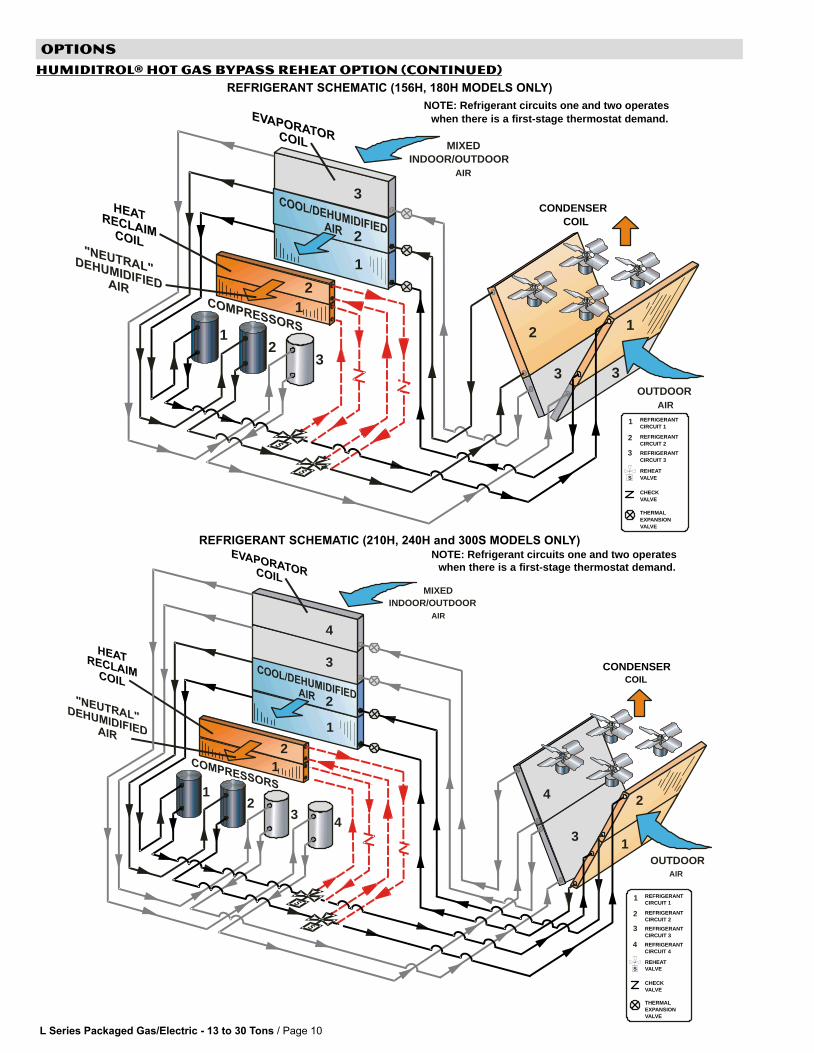
until the relative humidity of theconditioned space is 3% below thesetpoint.Reheat operation will initiate on adehumidification demand and does notrequire a cooling demand.The reheat coil is sized to offset most ofthe first stage sensible cooling effectduring reheat only operation. Thisreduction in sensible cooling capacityextends compressor run time to controlhumidity when cooling loads are light.Solenoid valves divert hot gas fromcompressor 1 and compressor 2 to thereheat coil.The cooled and dehumidified air fromthe evaporator is then reheated as itpasses through the reheat coil.The de−superheated and partiallycondensed refrigerant continues to theoutdoor condenser coil wherecondensing is completed.The unit will continue to operate in thismode until the dehumidification demandis satisfied.A heating demand will terminate reheatoperation.
Dehumidification and Cooling Demandfor 156H/180H three compressormodels (Thermostat Application)
If both a dehumidification and a firststage cooling demand occur, the systemwill operate compressor 1 andcompressor 2 in reheat and compressor3 will operate in cooling.A demand for second stage cooling willterminate reheat operation until secondstage cooling demand is satisfied.
Dehumidification and Cooling Demandfor 210H/240H/300S four compressormodels (Thermostat Application)
If both a dehumidification and a firststage cooling demand occur, the systemwill operate compressor 1 andcompressor 2 in reheat and compressor3 and compressor 4 will operate incooling.A demand for second stage cooling willterminate reheat operation until secondstage cooling demand is satisfied.
Dehumidification and CoolingDemand for 156H/180H threecompressor models (Room SensorApplication)
If both a dehumidification and a firststage cooling demand occur, the systemwill operate compressor 1 andcompressor 2 in reheat and compressor3 will operate in cooling.A demand for second stage cooling willterminate reheat and compressor 3operation and operate compressor 1and compressor 2 in cooling untilsecond stage cooling demand issatisfied.A demand for third stage cooling willoperate compressor 1, compressor 2and compressor 3 in cooling.
Dehumidification and CoolingDemand for 210H/240H/300S fourcompressor models (Room SensorApplication)
If both a dehumidification demand and afirst stage cooling demand occur, thesystem will operate compressor 1 andcompressor 2 in reheat and compressor3 will operate in cooling.If a demand for second stage cooling isinitiated, compressor 1 and compressor2 will operate in reheat and compressor3 and compressor 4 will operate incooling.A demand for third stage cooling willterminate reheat and compressor 4operation and operate compressor 1,compressor 2 and compressor 3 incooling until third stage cooling demandis satisfied. A demand for fourth stagecooling will operate compressor 1,compressor 2, compressor 3 andcompressor 4 in cooling.
L Series Packaged Gas/Electric − 13 to 30 Tons / Page 10
OPTIONS
HUMIDITROL® HOT GAS BYPASS REHEAT OPTION (CONTINUED)
REFRIGERANT SCHEMATIC (156H, 180H MODELS ONLY)
3 3
2 1
CONDENSERCOIL
NOTE: Refrigerant circuits one and two operates when there is a first-stage thermostat demand.
2
32
2
1
1
MIXEDINDOOR/OUTDOOR
AIR
OUTDOORAIR
1
3
2
THERMALEXPANSIONVALVE
CHECKVALVE
REHEATVALVE
REFRIGERANTCIRCUIT 1
REFRIGERANTCIRCUIT 2
REFRIGERANTCIRCUIT 3
S
3
2
1
REFRIGERANT SCHEMATIC (210H, 240H and 300S MODELS ONLY)
3 1
4 2
CONDENSERCOIL
NOTE: Refrigerant circuits one and two operates when there is a first-stage thermostat demand.
2
3 42
2
1
1
MIXEDINDOOR/OUTDOOR
AIR
OUTDOORAIR
1
3
2
4
THERMALEXPANSIONVALVE
CHECKVALVE
REHEATVALVE
REFRIGERANTCIRCUIT 1
REFRIGERANTCIRCUIT 2
REFRIGERANTCIRCUIT 3
REFRIGERANTCIRCUIT 4
S
3
4
2
1
L Series Packaged Gas/Electric − 13 to 30 Tons / Page 11
OPTIONs / ACCESSORIESL Series
Item
15
6
18
0
21
0
24
0
24
8
30
0S
30
0H
36
0
COOLING SYSTEM
Standard Efficiency Factory installed only � � � �
High Efficiency Factory installed only � � � � � � �
Condensate Drain Trap − Copper LTACDKC09/36 � � � � � � � �
Condensate Drain Trap − PVC LTACDKP09/36 � � � � � � � �
Corrosion Protection Factory installed only � � � � � � � �
Service Valves Factory installed only � � � � � � � �
Stainless Steel Condensate Drain Pan Factory installed only � � � � � � � �
HEATING SYSTEM
Low Heat (1 stage) Factory installed only � � �
Standard Heat (2 stage) Factory installed only � � � � � � � �
Medium Heat (2 stage) Factory installed only � � � � � � � �
High Heat (2 stage) Factory installed only � � � � � � �
Combustion Air Intake Extensions 89L97 1 x 1 x 1 x 1 x 1 x 1 x 1 x 1 x
LPG/Propane 130/260 (2 kits) kBtuh input − 72M94 1 x 1 x 1 x 1 x 1 x 1 x 1 x 1 xLPG/PropaneConversion Kits 180/360 (2 kits) kBtuh input − 72M95 1 x 1 x 1 x 1 x 1 x 1 x 1 x 1 x
240/480 (2 kits) kBtuh input − 72M96 1 x 1 x 1 x 1 x 1 x 1 x 1 x 1 x
Stainless Steel Heat Exchanger Factory installed only � � � � � � � �
Vertical Vent Extension 73M72 1 x 1 x 1 x 1 x 1 x 1 x 1 x 1 x
Blower − SUPPLY MOTOR
2, 3, 5 hp Std. Efficiency CAV �
2, 3, 5 hp High Efficiency CAV �
3, 5, 7.5 hp Std. Efficiency CAV � �
3, 5, 7.5 hp High. Efficiency CAV � �
5, 7.5, 10 hp Std. Efficiency CAV � � � � �
5, 7.5, 10 hp High Efficiency CAV � � � � �
5, 7.5, 10 hp Std. Efficiency VAV with VFD (not 575V units) � � �
5, 7.5, 10 hp High Efficiency VAV with VFD (not 575V units) � � �
Supply VFD Blower Bypass (VAV units with VFD only) � � �
AIR FILTERS
MERV 11 High Efficiency 97L87 (24 x 24 x 2 order 6 per unit) � � � � �MERV 11 High Efficiency
97L88 (20 x 20 x 2 order 12 per unit) � � �
CABINET
Coil Guards 88K52 x x x x xCoil Guards
88K53 x x x
Grille Guards 78K78 x x x x xGrille Guards
86K30 x x x
Hail Guards 88K25 x x x x xHail Guards
88K26 x x x
Horizontal Return Air Panel Kit 38K47 x x x x xHorizontal Return Air Panel Kit
38K48 x x x
CONTROLS
Blower Proving Switch 30K49 � � � � � � � �
Dehumidistat − Supermarket reheat only 65F86 x x x x x x x x
Commercial Controls L Connection® Building Automation System � � � � � � � �
Novar® ETM−2051 Unit Controller � � � � � � � �
Sectra� Zoning System w/ VFD Control − C0CTRL05BD1L � � �
Sectra� Zoning System with Bypass Control − C0CTRL04BD1L � � � � � � � �
Sectra� Zoning System Single Zone Control − C0CTRL03BD1L � � � � � � � �
Dirty Filter Switch 30K48 � � � � � � � �
2 Discharge Air Temperature Sensor Factory installed only � � �
Four Stage Control Factory installed only � � �
Fresh Air Tempering 45L78 ⊗ ⊗ ⊗ ⊗ ⊗ ⊗ ⊗ ⊗Smoke Detector − Supply LTSASDK10/36 � � � � � � � �
Smoke Detector − Return LTARSDK10/30 � � � � �
Smoke Detector − Return LTARSDK30/36 � � �
Supply Static Limit Switch C0SNSR11AE1 (Switch) x x x x x x x xSupply Static Limit Switch
C0SNSR12AE1− (Mounting Kit) x x x x x x x x2 Supply Static Transducer x x x
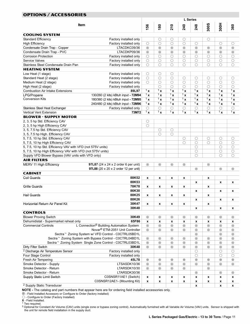
NOTE − The catalog and part numbers that appear here are for ordering field installed accessories only.⊗ − Field Installed Accessory or Configure to Order (factory installed)
� − Configure to Order (Factory Installed)X − Field Installed.1 Two required.2 Optional for Constant Air Volume (CAV) units (single zone or bypass zoning control). Automatically furnished with all Variable Air Volume (VAV) units. Sensor is shipped with the unit for remote field installation in the supply duct.
L Series Packaged Gas/Electric − 13 to 30 Tons / Page 12
OPTIONs / ACCESSORIESL Series
Item
15
6
18
0
21
0
24
0
24
8
30
0S
30
0H
36
0
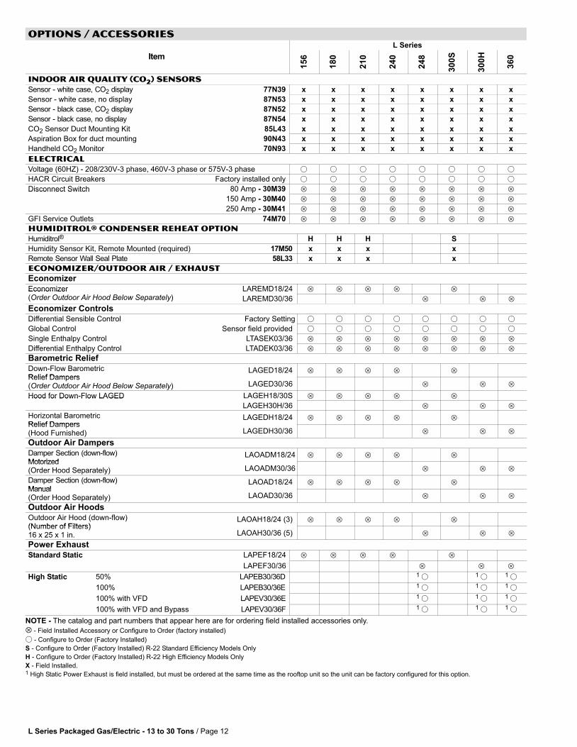
INDOOR AIR QUALITY (Co2) SENSORS
Sensor − white case, CO2 display 77N39 x x x x x x x x
Sensor − white case, no display 87N53 x x x x x x x x
Sensor − black case, CO2 display 87N52 x x x x x x x x
Sensor − black case, no display 87N54 x x x x x x x x
CO2 Sensor Duct Mounting Kit 85L43 x x x x x x x x
Aspiration Box for duct mounting 90N43 x x x x x x x x
Handheld CO2 Monitor 70N93 x x x x x x x x
ELECTRICAL
Voltage (60HZ) − 208/230V−3 phase, 460V−3 phase or 575V−3 phase � � � � � � � �
HACR Circuit Breakers Factory installed only � � � � � � � �
Disconnect Switch 80 Amp − 30M39 � � � � � � � �Disconnect Switch
150 Amp − 30M40 � � � � � � � �
250 Amp − 30M41 � � � � � � � �
GFI Service Outlets 74M70 � � � � � � � �
HUMIDITROL® CONDENSER REHEAT OPTION
Humiditrol® H H H S
Humidity Sensor Kit, Remote Mounted (required) 17M50 x x x x
Remote Sensor Wall Seal Plate 58L33 x x x x
ECONOMIZER/OUTDOOR AIR / EXHAUST
Economizer
Economizer LAREMD18/24 � � � � �Economizer(Order Outdoor Air Hood Below Separately) LAREMD30/36 � � �
Economizer Controls
Differential Sensible Control Factory Setting � � � � � � � �
Global Control Sensor field provided � � � � � � � �
Single Enthalpy Control LTASEK03/36 � � � � � � � �
Differential Enthalpy Control LTADEK03/36 � � � � � � � �
Barometric Relief
Down−Flow BarometricRelief Dampers
LAGED18/24 � � � � �
Relief Dampers(Order Outdoor Air Hood Below Separately) LAGED30/36 � � �
Hood for Down−Flow LAGED LAGEH18/30S � � � � �Hood for Down Flow LAGED
LAGEH30H/36 � � �
Horizontal Barometric Relief Dampers
LAGEDH18/24 � � � � �
Relief Dampers(Hood Furnished) LAGEDH30/36 � � �
Outdoor Air Dampers
Damper Section (down−flow)Motorized
LAOADM18/24 � � � � �
Motorized(Order Hood Separately) LAOADM30/36 � � �
Damper Section (down−flow)Manual
LAOAD18/24 � � � � �
Manual(Order Hood Separately) LAOAD30/36 � � �
Outdoor Air Hoods
Outdoor Air Hood (down−flow)(Number of Filters)
LAOAH18/24 (3) � � � � �
(Number of Filters)16 x 25 x 1 in. LAOAH30/36 (5) � � �
Power Exhaust
Standard Static LAPEF18/24 � � � � �
LAPEF30/36 � � �
High Static 50% LAPEB30/36D 1 � 1 � 1 �g
100% LAPEB30/36E 1 � 1 � 1 �
100% with VFD LAPEV30/36E 1 � 1 � 1 �
100% with VFD and Bypass LAPEV30/36F 1 � 1 � 1 �
NOTE − The catalog and part numbers that appear here are for ordering field installed accessories only.
⊗ − Field Installed Accessory or Configure to Order (factory installed)
� − Configure to Order (Factory Installed)
S − Configure to Order (Factory Installed) R−22 Standard Efficiency Models Only
H − Configure to Order (Factory Installed) R−22 High Efficiency Models Only
X − Field Installed.1 High Static Power Exhaust is field installed, but must be ordered at the same time as the rooftop unit so the unit can be factory configured for this option.
L Series Packaged Gas/Electric − 13 to 30 Tons / Page 13
OPTIONs / ACCESSORIESL Series
Item
15
6
18
0
21
0
24
0
24
8
30
0S
30
0H
36
0
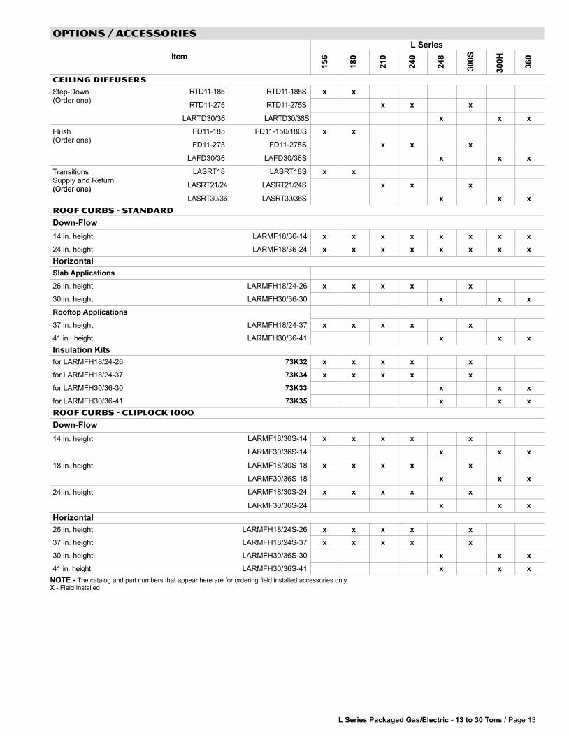
CEILING DIFFUSERS
Step−Down(O d )
RTD11−185 RTD11−185S x xp(Order one)
RTD11−275 RTD11−275S x x x
LARTD30/36 LARTD30/36S x x x
Flush(O d )
FD11−185 FD11−150/180S x x(Order one)
FD11−275 FD11−275S x x x
LAFD30/36 LAFD30/36S x x x
TransitionsS l d R t
LASRT18 LASRT18S x x
Supply and Return(Order one)
LASRT21/24 LASRT21/24S x x x(Order one)
LASRT30/36 LASRT30/36S x x x
ROOF CURBS − STANDARD
Down−Flow
14 in. height LARMF18/36−14 x x x x x x x x
24 in. height LARMF18/36−24 x x x x x x x x
Horizontal
Slab Applications
26 in. height LARMFH18/24−26 x x x x x
30 in. height LARMFH30/36−30 x x x
Rooftop Applications
37 in. height LARMFH18/24−37 x x x x x
41 in. height LARMFH30/36−41 x x x
Insulation Kits
for LARMFH18/24−26 73K32 x x x x x
for LARMFH18/24−37 73K34 x x x x x
for LARMFH30/36−30 73K33 x x x
for LARMFH30/36−41 73K35 x x x
ROOF CURBS − CLIPLOCK 1000
Down−Flow
14 in. height LARMF18/30S−14 x x x x xg
LARMF30/36S−14 x x x
18 in. height LARMF18/30S−18 x x x x xg
LARMF30/36S−18 x x x
24 in. height LARMF18/30S−24 x x x x xg
LARMF30/36S−24 x x x
Horizontal
26 in. height LARMFH18/24S−26 x x x x x
37 in. height LARMFH18/24S−37 x x x x x
30 in. height LARMFH30/36S−30 x x x
41 in. height LARMFH30/36S−41 x x x
NOTE − The catalog and part numbers that appear here are for ordering field installed accessories only.X − Field Installed

L Series Packaged Gas/Electric − 13 to 30 Tons / Page 14
SPECIFICATIONS − STANDARD EFFICIENCY COOLING (CAV) 15 TonGeneralData
Nominal Tonnage 15 TonData Model No. LGC180S2B (R−22)
Efficiency Type Standard
Blower Type Constant Air Volume (CAV)
CoolingP f
Gross Cooling Capacity − Btuh (kW) 186,000 (54.5)gPerformance 1 Net Cooling Capacity − Btuh (kW) 180,000 (52.7)
ARI Rated Air Flow − cfm (L/s) 6000 (2830)
Total Unit Power (kW) 18.01 EER (Btuh/Watt) 10.0
2 Integrated Part Load Value (Btuh/Watt) 10.6
Refrigerant ChargeFurnished (R 22)
Circuit 1 9 lbs. 0 oz. (4.08 kg)g gFurnished (R-22) Circuit 2 9 lbs. 0 oz. (4.08 kg)
Circuit 3 9 lbs. 0 oz. (4.08 kg)
Circuit 4 − − −
Gas HeatingPerformance
Heat Input Type Low1 Stage
Standard2 Stage
Medium2 Stage
High2 Stage
Input − Btuh (KW) First Stage 169,000 (49.5) 169,000 (49.5) 234,000 (68.6) 312,000 (91.4)
Second Stage − − − 260,000 (76.2) 360,000 (105.5) 480,000 (140.6)
Output − Btuh (kW) First Stage 135,000 (39.6) − − − − − − − − −
Second Stage − − − 208,000 (60.9) 288,000 (84.4) 384,000 (112.5)
CSA Thermal Efficiency 80.0%
Gas Supply Connections 1 in.
Recommended Gas Supply Pressure − Natural 7 in. w.g. (1.7 kPa)
LPG/Propane 11 in. w.g. (2.7 kPa)
Compressor Type (no.) Scroll (3)
CondenserC il
Net face area − sq. ft. (m2) total 56.5 (5.25)Coils Tube diameter − in. (mm) 3/8 (9.5)
Number of rows 1
Fins per inch (m) 20 (787)
CondenserF
Motor horsepower (W) (4) 1/3 (249)Fans Motor rpm 1075
Total Motor watts 1370
Diameter − in. (mm) (4) 24 (610)
No. of blades 3
Total Air volume − cfm (L/s) 15,850 (7480)
EvaporatorC il
Net face area − sq. ft. (m2) total 22.3 (2.07)pCoils Tube diameter − in. (mm) 3/8 (9.5)
No. of rows 3
Fins per inch (m) 14 (551)
Drain connection − number and size (1) 1 in. NPT coupling
Expansion device type Balanced Port Thermostatic Expansion Valve, removeable power head3 IndoorBlower andDrive
Nominal motor output 3 hp (2.2 kW)5 hp (3.7 kW)
7.5 hp (5.6 kW)DriveSelection Maximum usable motor output
(US Only)3.45 hp (2.6 kW)5.75 hp (4.3 kW)8.63 hp (6.4 kW)
Motor − Drive kit 3 hpkit #A − 535 − 725 rpmkit #1 − 685 − 865 rpmkit #2 − 685 − 865 rpm
5 hpkit #2 − 685 − 865 rpmkit #3 − 850 − 1045 rpmkit #4 − 945 − 1185 rpm
7.5 hpkit# 5 − 945 − 1185 rpm
kit# 6 − 1045 − 1285 rpmkit# 7 − 850 − 1045 rpm
Blower�wheel�nominal�diameter�x�width (2) 15 x 15 in. (381 x 381 mm)
Filters Type of filter Disposable, pleated MERV 7 (standard) or MERV 11 (optional)
No. and size − in. (mm) (6) 24 x 24 x 2 (610 x 610 x 51)
Electrical characteristics 208/230V, 460V or 575V − 60 hertz − 3 phase
NOTE − Net capacity includes evaporator blower motor heat deduction. Gross capacity does not include evaporator blower motor heat deduction.1 Certified in accordance with the ULE certification program, which is based on ARI Standard 340/360; 95�F (35�C) outdoor air temperature and 80�F (27�C) db/67�F
(19�C) wb entering evaporator air; minimum external duct static pressure.2 Integrated Part Load Value tested at 80�F (27�C) outdoor air temperature.3 Using total air volume and system static pressure requirements determine from blower performance tables rpm and motor output required. Maximum usable output of
motors furnished by Lennox are shown. In Canada, nominal motor output is also maximum usable motor output. If motors of comparable output are used, be sure to keepwithin the service factor limitations outlined on the motor nameplate.
L Series Packaged Gas/Electric − 13 to 30 Tons / Page 15
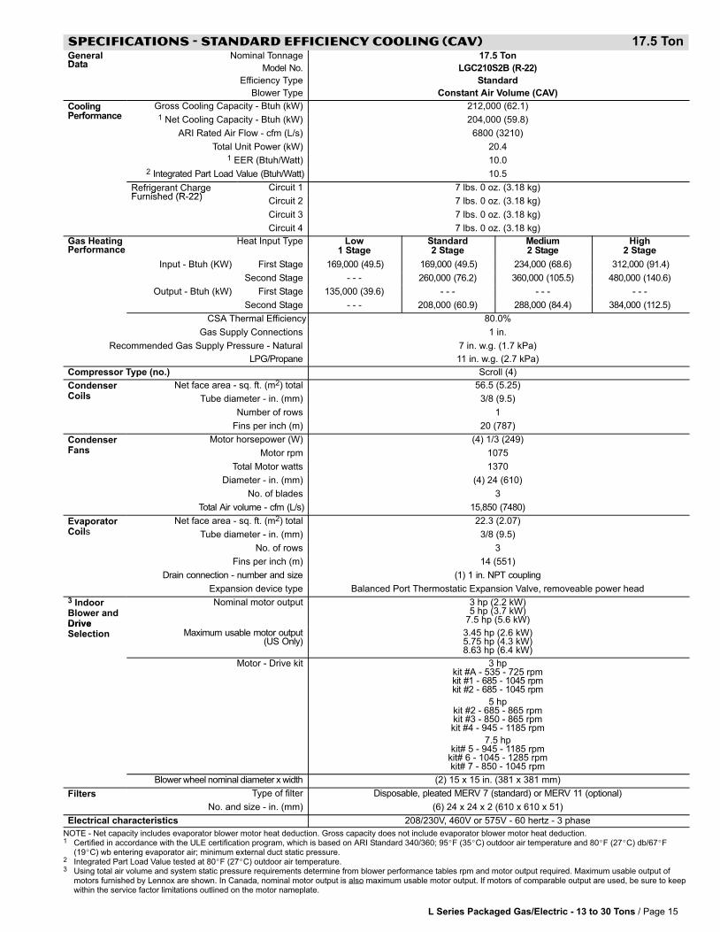
SPECIFICATIONS − STANDARD EFFICIENCY COOLING (CAV) 17.5 TonGeneralData
Nominal Tonnage 17.5 TonData Model No. LGC210S2B (R−22)
Efficiency Type Standard
Blower Type Constant Air Volume (CAV)
CoolingP f
Gross Cooling Capacity − Btuh (kW) 212,000 (62.1)gPerformance 1 Net Cooling Capacity − Btuh (kW) 204,000 (59.8)
ARI Rated Air Flow − cfm (L/s) 6800 (3210)
Total Unit Power (kW) 20.41 EER (Btuh/Watt) 10.0
2 Integrated Part Load Value (Btuh/Watt) 10.5
Refrigerant ChargeFurnished (R 22)
Circuit 1 7 lbs. 0 oz. (3.18 kg)g gFurnished (R-22) Circuit 2 7 lbs. 0 oz. (3.18 kg)
Circuit 3 7 lbs. 0 oz. (3.18 kg)
Circuit 4 7 lbs. 0 oz. (3.18 kg)
Gas HeatingPerformance
Heat Input Type Low1 Stage
Standard2 Stage
Medium2 Stage
High2 Stage
Input − Btuh (KW) First Stage 169,000 (49.5) 169,000 (49.5) 234,000 (68.6) 312,000 (91.4)
Second Stage − − − 260,000 (76.2) 360,000 (105.5) 480,000 (140.6)
Output − Btuh (kW) First Stage 135,000 (39.6) − − − − − − − − −
Second Stage − − − 208,000 (60.9) 288,000 (84.4) 384,000 (112.5)
CSA Thermal Efficiency 80.0%
Gas Supply Connections 1 in.
Recommended Gas Supply Pressure − Natural 7 in. w.g. (1.7 kPa)
LPG/Propane 11 in. w.g. (2.7 kPa)
Compressor Type (no.) Scroll (4)
CondenserC il
Net face area − sq. ft. (m2) total 56.5 (5.25)Coils Tube diameter − in. (mm) 3/8 (9.5)
Number of rows 1
Fins per inch (m) 20 (787)
CondenserF
Motor horsepower (W) (4) 1/3 (249)Fans Motor rpm 1075
Total Motor watts 1370
Diameter − in. (mm) (4) 24 (610)
No. of blades 3
Total Air volume − cfm (L/s) 15,850 (7480)
EvaporatorC il
Net face area − sq. ft. (m2) total 22.3 (2.07)pCoils Tube diameter − in. (mm) 3/8 (9.5)
No. of rows 3
Fins per inch (m) 14 (551)
Drain connection − number and size (1) 1 in. NPT coupling
Expansion device type Balanced Port Thermostatic Expansion Valve, removeable power head
3 IndoorBlower andDrive
Nominal motor output 3 hp (2.2 kW)5 hp (3.7 kW)
7.5 hp (5.6 kW)DriveSelection Maximum usable motor output
(US Only)3.45 hp (2.6 kW)5.75 hp (4.3 kW)8.63 hp (6.4 kW)
Motor − Drive kit 3 hpkit #A − 535 − 725 rpmkit #1 − 685 − 1045 rpmkit #2 − 685 − 1045 rpm
5 hpkit #2 − 685 − 865 rpmkit #3 − 850 − 865 rpmkit #4 − 945 − 1185 rpm
7.5 hpkit# 5 − 945 − 1185 rpm
kit# 6 − 1045 − 1285 rpmkit# 7 − 850 − 1045 rpm
Blower�wheel�nominal�diameter�x�width (2) 15 x 15 in. (381 x 381 mm)
Filters Type of filter Disposable, pleated MERV 7 (standard) or MERV 11 (optional)
No. and size − in. (mm) (6) 24 x 24 x 2 (610 x 610 x 51)
Electrical characteristics 208/230V, 460V or 575V − 60 hertz − 3 phase
NOTE − Net capacity includes evaporator blower motor heat deduction. Gross capacity does not include evaporator blower motor heat deduction.1 Certified in accordance with the ULE certification program, which is based on ARI Standard 340/360; 95�F (35�C) outdoor air temperature and 80�F (27�C) db/67�F
(19�C) wb entering evaporator air; minimum external duct static pressure.2 Integrated Part Load Value tested at 80�F (27�C) outdoor air temperature.3 Using total air volume and system static pressure requirements determine from blower performance tables rpm and motor output required. Maximum usable output of
motors furnished by Lennox are shown. In Canada, nominal motor output is also maximum usable motor output. If motors of comparable output are used, be sure to keepwithin the service factor limitations outlined on the motor nameplate.
L Series Packaged Gas/Electric − 13 to 30 Tons / Page 16
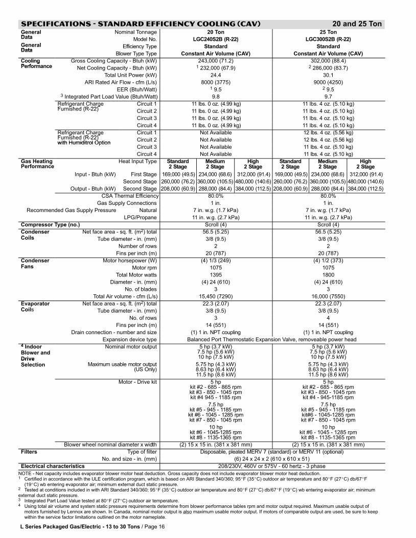
SPECIFICATIONS − STANDARD EFFICIENCY COOLING (CAV) 20 and 25 TonGeneralData
Nominal Tonnage 20 Ton 25 TonData
G lModel No. LGC240S2B (R−22) LGC300S2B (R−22)
GeneralData
Efficiency Type Standard StandardData
Blower Type Type Constant Air Volume (CAV) Constant Air Volume (CAV)
CoolingP f
Gross Cooling Capacity − Btuh (kW) 243,000 (71.2) 302,000 (88.4)gPerformance Net Cooling Capacity − Btuh (kW) 1 232,000 (67.9) 2 286,000 (83.7)
Total Unit Power (kW) 24.4 30.1
ARI Rated Air Flow − cfm (L/s) 8000 (3775) 9000 (4250)
EER (Btuh/Watt) 1 9.5 2 9.53 Integrated Part Load Value (Btuh/Watt) 9.8 9.7
Refrigerant ChargeFurnished (R 22)
Circuit 1 11 lbs. 0 oz. (4.99 kg) 11 lbs. 4 oz. (5.10 kg)g gFurnished (R-22) Circuit 2 11 lbs. 0 oz. (4.99 kg) 11 lbs. 4 oz. (5.10 kg)
Circuit 3 11 lbs. 0 oz. (4.99 kg) 11 lbs. 4 oz. (5.10 kg)
Circuit 4 11 lbs. 0 oz. (4.99 kg) 11 lbs. 4 oz. (5.10 kg)
Refrigerant ChargeFurnished (R 22)
Circuit 1 Not Available 12 lbs. 4 oz. (5.56 kg)g gFurnished (R-22)with Humiditrol Option
Circuit 2 Not Available 12 lbs. 4 oz. (5.56 kg)with Humiditrol Option
Circuit 3 Not Available 11 lbs. 4 oz. (5.10 kg)
Circuit 4 Not Available 11 lbs. 4 oz. (5.10 kg)
Gas HeatingPerformance
Heat Input Type Standard2 Stage
Medium2 Stage
High2 Stage
Standard2 Stage
Medium2 Stage
High2 Stage
Input − Btuh (kW) First Stage 169,000 (49.5) 234,000 (68.6) 312,000 (91.4) 169,000 (49.5) 234,000 (68.6) 312,000 (91.4)
Second Stage 260,000 (76.2) 360,000 (105.5) 480,000 (140.6) 260,000 (76.2) 360,000 (105.5) 480,000 (140.6)
Output − Btuh (kW) Second Stage 208,000 (60.9) 288,000 (84.4) 384,000 (112.5) 208,000 (60.9) 288,000 (84.4) 384,000 (112.5)
CSA Thermal Efficiency 80.0% 80.0%
Gas Supply Connections 1 in. 1 in.
Recommended Gas Supply Pressure Natural 7 in. w.g. (1.7 kPa) 7 in. w.g. (1.7 kPa)
LPG/Propane 11 in. w.g. (2.7 kPa) 11 in. w.g. (2.7 kPa)
Compressor Type (no.) Scroll (4) Scroll (4)
CondenserC il
Net face area − sq. ft. (m2) total 56.5 (5.25) 56.5 (5.25)Coils Tube diameter − in. (mm) 3/8 (9.5) 3/8 (9.5)
Number of rows 2 2
Fins per inch (m) 20 (787) 20 (787)
CondenserF
Motor horsepower (W) (4) 1/3 (249) (4) 1/2 (373)Fans Motor rpm 1075 1075
Total Motor watts 1395 1800
Diameter − in. (mm) (4) 24 (610) (4) 24 (610)
No. of blades 3 3
Total Air volume − cfm (L/s) 15,450 (7290) 16,000 (7550)
EvaporatorC il
Net face area − sq. ft. (m2) total 22.3 (2.07) 22.3 (2.07)pCoils Tube diameter − in. (mm) 3/8 (9.5) 3/8 (9.5)
No. of rows 3 4
Fins per inch (m) 14 (551) 14 (551)
Drain connection − number and size (1) 1 in. NPT coupling (1) 1 in. NPT coupling
Expansion device type Balanced Port Thermostatic Expansion Valve, removeable power head4 IndoorBlower andDrive
Nominal motor output 5 hp (3.7 kW)7.5 hp (5.6 kW)10 hp (7.5 kW)
5 hp (3.7 kW)7.5 hp (5.6 kW)10 hp (7.5 kW)Drive
Selection Maximum usable motor output(US Only)
5.75 hp (4.3 kW)8.63 hp (6.4 kW)11.5 hp (8.6 kW)
5.75 hp (4.3 kW)8.63 hp (6.4 kW)11.5 hp (8.6 kW)
Motor − Drive kit 5 hpkit #2 − 685 − 865 rpmkit #3 − 850 − 1045 rpmkit #4 945 − 1185 rpm
7.5 hpkit #5 − 945 − 1185 rpm
kit #6 − 1045 − 1285 rpmkit #7 − 850 − 1045 rpm
10 hpkit #6 − 1045−1285 rpmkit #8 − 1135−1365 rpm
5 hpkit #2 − 685 − 865 rpmkit #3 − 850 − 1045 rpmkit #4 − 945−1185 rpm
7.5 hpkit #5 − 945 − 1185 rpmkit#6 − 1045−1285 rpmkit #7 − 850 − 1045 rpm
10 hpkit #6 − 1045 − 1285 rpmkit #8 − 1135−1365 rpm
Blower�wheel�nominal�diameter�x�width (2) 15 x 15 in. (381 x 381 mm) (2) 15 x 15 in. (381 x 381 mm)
Filters Type of filter Disposable, pleated MERV 7 (standard) or MERV 11 (optional)
No. and size − in. (mm) (6) 24 x 24 x 2 (610 x 610 x 51)
Electrical characteristics 208/230V, 460V or 575V − 60 hertz − 3 phase
NOTE − Net capacity includes evaporator blower motor heat deduction. Gross capacity does not include evaporator blower motor heat deduction.1 Certified in accordance with the ULE certification program, which is based on ARI Standard 340/360; 95�F (35�C) outdoor air temperature and 80�F (27�C) db/67�F
(19�C) wb entering evaporator air; minimum external duct static pressure.2 Tested at conditions included in with ARI Standard 340/360; 95�F (35�C) outdoor air temperature and 80�F (27�C) db/67�F (19�C) wb entering evaporator air; minimumexternal duct static pressure.3 Integrated Part Load Value tested at 80�F (27�C) outdoor air temperature.4 Using total air volume and system static pressure requirements determine from blower performance tables rpm and motor output required. Maximum usable output of
motors furnished by Lennox are shown. In Canada, nominal motor output is also maximum usable motor output. If motors of comparable output are used, be sure to keepwithin the service factor limitations outlined on the motor nameplate.

L Series Packaged Gas/Electric − 13 to 30 Tons / Page 17
SPECIFICATIONS − HIGH EFFICIENCY COOLING (CAV) 13 TonGeneralD t
Nominal Tonnage 13 TonGeneralData Model No. LGC156H2B (R−22)
Efficiency Type High
Blower Type Type Constant Air Volume (CAV)
CoolingP f
Gross Cooling Capacity − Btuh (kW) 160,000 (46.8)CoolingPerformance 1 Net Cooling Capacity − Btuh (kW) 156,000 (45.7)
ARI Rated Air Flow − cfm (L/s) 5100 (2405)
Total Unit Power (kW) 12.81 EER (Btuh/Watt) 12.2
2 Integrated Part Load Value (Btuh/Watt) 13.6
Refrigerant Charge F i h d (R 22)
Circuit 1 11 lbs. 0 oz. (4.99 kg)Refrigerant Charge Furnished (R-22)
Circuit 2 11 lbs. 0 oz. (4.99 kg)
Circuit 3 11 lbs. 0 oz. (4.99 kg)
Refrigerant Charge F i h d (R 22)
Circuit 1 13 lbs. 8 oz. (6.12 kg)Refrigerant Charge Furnished (R-22)with Humiditrol Option Circuit 2 13 lbs. 8 oz. (6.12 kg)with Humiditrol Option
Circuit 3 11 lbs. 0 oz. (4.99 kg)
Gas HeatingPerformance
Heat Input Type Low1 Stage
Standard2 Stage
Medium2 Stage
Input − Btuh (kW) First Stage 169,000 (49.5) 169,000 (49.5) 234,000 (68.6)
Second Stage − − − 260,000 (76.2) 360,000 (105.5)
Output − Btuh (kW) First Stage 135,000 (39.6) − − − − − −
Second Stage − − − 208,000 (60.9) 288,000 (84.4)
CSA Thermal Efficiency 80.0%
Gas Supply Connections 1 in.
Recommended Gas Supply Pressure Natural 7 in. w.g. (1.7 kPa)
LPG/Propane 11 in. w.g. (2.7 kPa)
Compressor Type (no.) Scroll (3)
CondenserC il
Net face area − sq. ft. (m2) total 56.5 (5.25)CondenserCoils Tube diameter − in. (mm) − No. of rows 3/8 (9.5) − 2
Fins per inch (m) 20 (787)
CondenserF
Motor horsepower (W) (4) 1/3 (249)CondenserFans Motor rpm 1075
Total Motor watts 1395
Diameter − in. (mm) − No. of blades (4) 24 (610) − 3
Total Air volume − cfm (L/s) 15,450 (7290)
EvaporatorC il
Net face area − sq. ft. (m2) total 22.3 (2.07)EvaporatorCoils Tube diameter − in. (mm) − No. of rows 3/8 (9.5) − 3
Fins per inch (m) 14 (551)
Condensate Drain − number and size (1) 1 in. NPT coupling
Expansion device type Balanced Port Thermostatic Expansion Valve, removeable power head3 IndoorBlower andDrive
Nominal motor output 2 hp (1.5 kW)3 hp (2.2 kW)5 hp (3.7 kW)Drive
Selection Maximum usable motor output(US Only)
2.3 hp (1.7 kW)3.45 hp (2.6 kW)5.75 hp (4.3 kW)
Motor − Drive kit number 2 hpkit #A − 535 − 725 rpm
3 hpkit #A − 535 − 725 rpmkit #1 − 685 − 865 rpmkit #2 − 685 − 865 rpm
5 hpkit #2 − 685 − 865 rpmkit #3 − 850 − 1045 rpmkit #4 − 945 − 1185 rpm
Blower�wheel�nom. dia.�x�width�−�in.�(mm) (2) 15 x 15 (381 x 381)
Filters Type of filter Disposable, pleated MERV 7 (standard) or MERV 11 (optional)Filters
No. and size − in. (mm) (6) 24 x 24 x 2 (610 x 610 x 51)
Electrical characteristics 208/230V, 460V or 575V − 60 hertz − 3 phase
NOTE − Net capacity includes evaporator blower motor heat deduction. Gross capacity does not include evaporator blower motor heat deduction.1 Certified in accordance with the ULE certification program, which is based on ARI Standard 340/360; 95�F (35�C) outdoor air temperature and 80�F (27�C) db/67�F
(19�C) wb entering evaporator air; minimum external duct static pressure.2 Integrated Part Load Value tested at 80�F (27�C) outdoor air temperature.3 Using total air volume and system static pressure requirements determine from blower performance tables rpm and motor output required. Maximum usable output of
motors furnished by Lennox are shown. In Canada, nominal motor output is also maximum usable motor output. If motors of comparable output are used, be sure to keepwithin the service factor limitations outlined on the motor nameplate.
L Series Packaged Gas/Electric − 13 to 30 Tons / Page 18
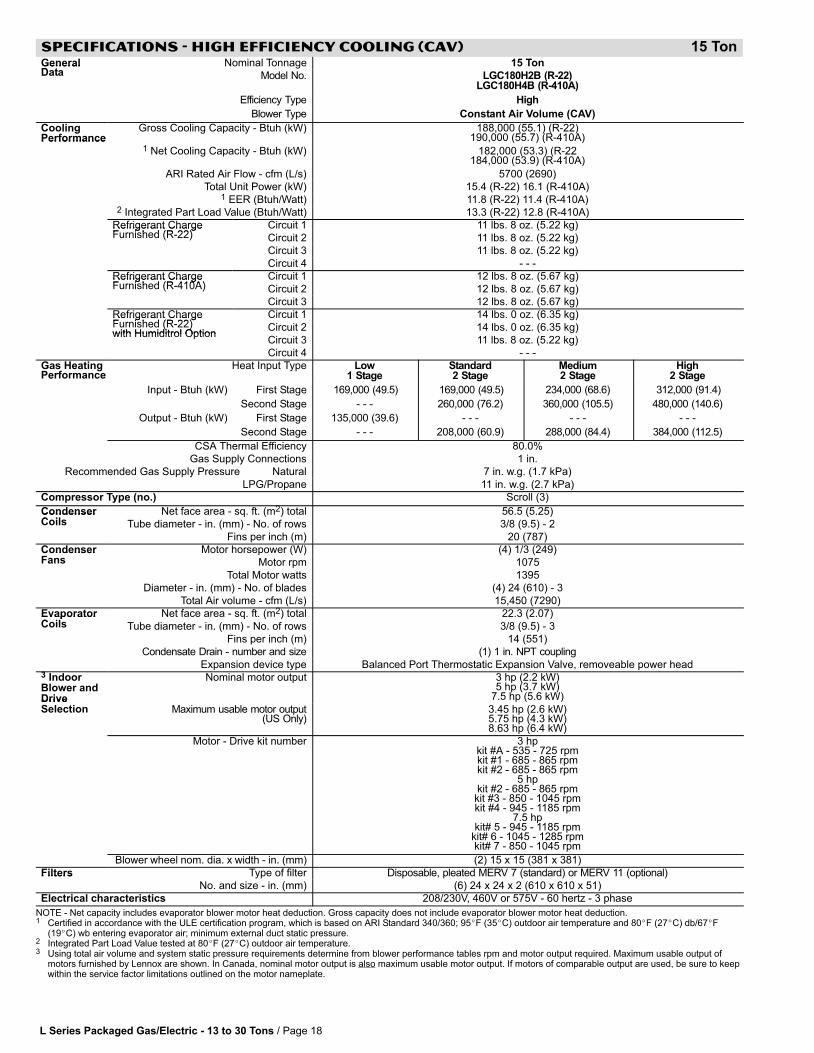
SPECIFICATIONS − HIGH EFFICIENCY COOLING (CAV) 15 TonGeneralD t
Nominal Tonnage 15 TonGeneralData Model No. LGC180H2B (R−22)
LGC180H4B (R−410A)
Efficiency Type High
Blower Type Constant Air Volume (CAV)
CoolingPerformance
Gross Cooling Capacity − Btuh (kW) 188,000 (55.1) (R−22)190,000 (55.7) (R−410A)Performance
1 Net Cooling Capacity − Btuh (kW) 182,000 (53.3) (R−22184,000 (53.9) (R−410A)
ARI Rated Air Flow − cfm (L/s) 5700 (2690)
Total Unit Power (kW) 15.4 (R−22) 16.1 (R−410A)1 EER (Btuh/Watt) 11.8 (R−22) 11.4 (R−410A)
2 Integrated Part Load Value (Btuh/Watt) 13.3 (R−22) 12.8 (R−410A)
Refrigerant Charge F i h d (R 22)
Circuit 1 11 lbs. 8 oz. (5.22 kg)Refrigerant Charge Furnished (R-22) Circuit 2 11 lbs. 8 oz. (5.22 kg)( )
Circuit 3 11 lbs. 8 oz. (5.22 kg)
Circuit 4 − − −
Refrigerant Charge F i h d (R 410A)
Circuit 1 12 lbs. 8 oz. (5.67 kg)Refrigerant Charge Furnished (R-410A) Circuit 2 12 lbs. 8 oz. (5.67 kg)( )
Circuit 3 12 lbs. 8 oz. (5.67 kg)
Refrigerant Charge F i h d (R 22)
Circuit 1 14 lbs. 0 oz. (6.35 kg)Refrigerant Charge Furnished (R-22)with Humiditrol Option
Circuit 2 14 lbs. 0 oz. (6.35 kg)( )with Humiditrol Option
Circuit 3 11 lbs. 8 oz. (5.22 kg)
Circuit 4 − − −
Gas HeatingPerformance
Heat Input Type Low1 Stage
Standard2 Stage
Medium2 Stage
High2 Stage
Input − Btuh (kW) First Stage 169,000 (49.5) 169,000 (49.5) 234,000 (68.6) 312,000 (91.4)
Second Stage − − − 260,000 (76.2) 360,000 (105.5) 480,000 (140.6)
Output − Btuh (kW) First Stage 135,000 (39.6) − − − − − − − − −
Second Stage − − − 208,000 (60.9) 288,000 (84.4) 384,000 (112.5)
CSA Thermal Efficiency 80.0%
Gas Supply Connections 1 in.
Recommended Gas Supply Pressure Natural 7 in. w.g. (1.7 kPa)
LPG/Propane 11 in. w.g. (2.7 kPa)
Compressor Type (no.) Scroll (3)
CondenserC il
Net face area − sq. ft. (m2) total 56.5 (5.25)CondenserCoils Tube diameter − in. (mm) − No. of rows 3/8 (9.5) − 2
Fins per inch (m) 20 (787)
CondenserF
Motor horsepower (W) (4) 1/3 (249)CondenserFans Motor rpm 1075
Total Motor watts 1395
Diameter − in. (mm) − No. of blades (4) 24 (610) − 3
Total Air volume − cfm (L/s) 15,450 (7290)
EvaporatorC il
Net face area − sq. ft. (m2) total 22.3 (2.07)EvaporatorCoils Tube diameter − in. (mm) − No. of rows 3/8 (9.5) − 3
Fins per inch (m) 14 (551)
Condensate Drain − number and size (1) 1 in. NPT coupling
Expansion device type Balanced Port Thermostatic Expansion Valve, removeable power head3 IndoorBlower andDrive
Nominal motor output 3 hp (2.2 kW)5 hp (3.7 kW)
7.5 hp (5.6 kW)DriveSelection Maximum usable motor output
(US Only)3.45 hp (2.6 kW)5.75 hp (4.3 kW)8.63 hp (6.4 kW)
Motor − Drive kit number 3 hpkit #A − 535 − 725 rpmkit #1 − 685 − 865 rpmkit #2 − 685 − 865 rpm
5 hpkit #2 − 685 − 865 rpmkit #3 − 850 − 1045 rpmkit #4 − 945 − 1185 rpm
7.5 hpkit# 5 − 945 − 1185 rpm
kit# 6 − 1045 − 1285 rpmkit# 7 − 850 − 1045 rpm
Blower�wheel�nom. dia.�x�width�−�in.�(mm) (2) 15 x 15 (381 x 381)
Filters Type of filter Disposable, pleated MERV 7 (standard) or MERV 11 (optional)Filters
No. and size − in. (mm) (6) 24 x 24 x 2 (610 x 610 x 51)
Electrical characteristics 208/230V, 460V or 575V − 60 hertz − 3 phase
NOTE − Net capacity includes evaporator blower motor heat deduction. Gross capacity does not include evaporator blower motor heat deduction.1 Certified in accordance with the ULE certification program, which is based on ARI Standard 340/360; 95�F (35�C) outdoor air temperature and 80�F (27�C) db/67�F
(19�C) wb entering evaporator air; minimum external duct static pressure.2 Integrated Part Load Value tested at 80�F (27�C) outdoor air temperature.3 Using total air volume and system static pressure requirements determine from blower performance tables rpm and motor output required. Maximum usable output of
motors furnished by Lennox are shown. In Canada, nominal motor output is also maximum usable motor output. If motors of comparable output are used, be sure to keepwithin the service factor limitations outlined on the motor nameplate.
L Series Packaged Gas/Electric − 13 to 30 Tons / Page 19
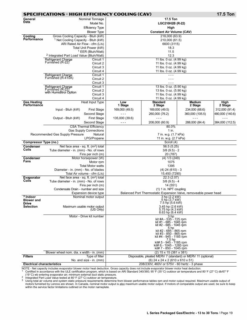
SPECIFICATIONS − HIGH EFFICIENCY COOLING (CAV) 17.5 TonGeneralData
Nominal Tonnage 17.5 TonData Model No. LGC210H2B (R−22)
Efficiency Type High
Blower Type Constant Air Volume (CAV)
CoolingP f
Gross Cooling Capacity − Btuh (kW) 218,000 (63.9)CoolingPerformance 1 Net Cooling Capacity − Btuh (kW) 210,000 (61.5)
ARI Rated Air Flow − cfm (L/s) 6600 (3115)
Total Unit Power (kW) 18.31 EER (Btuh/Watt) 11.5
2 Integrated Part Load Value (Btuh/Watt) 12.3
Refrigerant Charge F i h d (R 22)
Circuit 1 11 lbs. 0 oz. (4.99 kg)Refrigerant Charge Furnished (R-22) Circuit 2 11 lbs. 0 oz. (4.99 kg)( )
Circuit 3 11 lbs. 0 oz. (4.99 kg)
Circuit 4 11 lbs. 0 oz. (4.99 kg)
Refrigerant Charge F i h d (R 410A)
Circuit 1 − − −Refrigerant Charge Furnished (R-410A) Circuit 2 − − −( )
Circuit 3 − − −
Refrigerant Charge F i h d (R 22)
Circuit 1 13 lbs. 0 oz. (5.90 kg)Refrigerant Charge Furnished (R-22)with Humiditrol Option
Circuit 2 13 lbs. 0 oz. (5.90 kg)( )with Humiditrol Option
Circuit 3 11 lbs. 0 oz. (4.99 kg)
Circuit 4 11 lbs. 0 oz. (4.99 kg)
Gas HeatingPerformance
Heat Input Type Low1 Stage
Standard2 Stage
Medium2 Stage
High2 Stage
Input − Btuh (kW) First Stage 169,000 (49.5) 169,000 (49.5) 234,000 (68.6) 312,000 (91.4)
Second Stage − − − 260,000 (76.2) 360,000 (105.5) 480,000 (140.6)
Output − Btuh (kW) First Stage 135,000 (39.6) − − − − − − − − −
Second Stage − − − 208,000 (60.9) 288,000 (84.4) 384,000 (112.5)
CSA Thermal Efficiency 80.0%
Gas Supply Connections 1 in.
Recommended Gas Supply Pressure Natural 7 in. w.g. (1.7 kPa)
LPG/Propane 11 in. w.g. (2.7 kPa)
Compressor Type (no.) Scroll (4)
CondenserC il
Net face area − sq. ft. (m2) total 56.5 (5.25)CondenserCoils Tube diameter − in. (mm) − No. of rows 3/8 (9.5) − 2
Fins per inch (m) 20 (787)
CondenserF
Motor horsepower (W) (4) 1/3 (249)CondenserFans Motor rpm 1075
Total Motor watts 1395
Diameter − in. (mm) − No. of blades (4) 24 (610) − 3
Total Air volume − cfm (L/s) 15,450 (7290)
EvaporatorC il
Net face area − sq. ft. (m2) total 22.3 (2.07)EvaporatorCoils Tube diameter − in. (mm) − No. of rows 3/8 (9.5) − 4
Fins per inch (m) 14 (551)
Condensate Drain − number and size (1) 1 in. NPT coupling
Expansion device type Balanced Port Thermostatic Expansion Valve, removeable power head3 IndoorBlower andDrive
Nominal motor output 3 hp (2.2 kW)5 hp (3.7 kW)
7.5 hp (5.6 kW)DriveSelection Maximum usable motor output
(US Only)3.45 hp (2.6 kW)5.75 hp (4.3 kW)8.63 hp (6.4 kW)
Motor − Drive kit number 3 hpkit #A − 535 − 725 rpmkit #1 − 685 − 1045 rpmkit #2 − 685 − 1045 rpm
5 hpkit #2 − 685 − 865 rpmkit #3 − 850 − 865 rpmkit #4 − 945 − 1185 rpm
7.5 hpkit# 5 − 945 − 1185 rpm
kit# 6 − 1045 − 1285 rpmkit# 7 − 850 − 1045 rpm
Blower�wheel�nom. dia.�x�width�−�in.�(mm) (2) 15 x 15 (381 x 381)
Filters Type of filter Disposable, pleated MERV 7 (standard) or MERV 11 (optional)Filters
No. and size − in. (mm) (6) 24 x 24 x 2 (610 x 610 x 51)
Electrical characteristics 208/230V, 460V or 575V − 60 hertz − 3 phase
NOTE − Net capacity includes evaporator blower motor heat deduction. Gross capacity does not include evaporator blower motor heat deduction.1 Certified in accordance with the ULE certification program, which is based on ARI Standard 340/360; 95�F (35�C) outdoor air temperature and 80�F (27�C) db/67�F
(19�C) wb entering evaporator air; minimum external duct static pressure.2 Integrated Part Load Value tested at 80�F (27�C) outdoor air temperature.3 Using total air volume and system static pressure requirements determine from blower performance tables rpm and motor output required. Maximum usable output of
motors furnished by Lennox are shown. In Canada, nominal motor output is also maximum usable motor output. If motors of comparable output are used, be sure to keepwithin the service factor limitations outlined on the motor nameplate.
L Series Packaged Gas/Electric − 13 to 30 Tons / Page 20
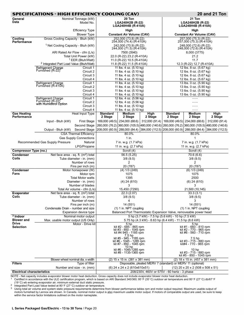
SPECIFICATIONS − HIGH EFFICIENCY COOLING (CAV) 20 and 21 TonGeneralD t
Nominal Tonnage (kW) 20 Ton 21 TonGeneralData Model No. LGA240H2B (R−22)
LGA240H4B (R−410A)LGA248H2B (R−22)
LGA248H4B (R−410A)
Efficiency Type High High
Blower Type Constant Air Volume (CAV) Constant Air Volume (CAV)
CoolingPerformance
Gross Cooling Capacity − Btuh (kW) 252,000 (73.8) (R−22)254,000 (74.4) (R−410A)
257,000 (75.3) (R−22)257,000 (75.3) (R−410A)Performance
1 Net Cooling Capacity − Btuh (kW) 242,000 (70.9) (R−22)244,000 (71.5) (R−410A)
248,000 (72.6) (R−22)248,000 (72.6) (R−410A)
ARI Rated Air Flow − cfm (L/s) 7500 (3540) 8,000 (3775)
Total Unit Power (kW) 22.0 (R−22) 23.2 (R−410A) 21.21 EER (Btuh/Watt) 11.0 (R−22) 10.5 (R−410A) 11.7
2 Integrated Part Load Value (Btuh/Watt) 11.8 (R−22) 11.5 (R−410A) 12.3 (R−22) 12.7 (R−410A)
Refrigerant ChargeF i h d (R 22)
Circuit 1 11 lbs. 4 oz. (5.10 kg) 12 lbs. 8 oz. (5.67 kg)Refrigerant ChargeFurnished (R-22) Circuit 2 11 lbs. 4 oz. (5.10 kg) 12 lbs. 8 oz. (5.67 kg)( )
Circuit 3 11 lbs. 4 oz. (5.10 kg) 12 lbs. 8 oz. (5.67 kg)
Circuit 4 11 lbs. 4 oz. (5.10 kg) 12 lbs. 8 oz. (5.67 kg)
Refrigerant ChargeF i h d (R 410A)
Circuit 1 11 lbs. 4 oz. (5.10 kg) 13 lbs. 0 oz. (5.90 kg)Refrigerant ChargeFurnished (R-410A) Circuit 2 11 lbs. 4 oz. (5.10 kg) 13 lbs. 0 oz. (5.90 kg)( )
Circuit 3 11 lbs. 4 oz. (5.10 kg) 13 lbs. 0 oz. (5.90 kg)
Circuit 4 11 lbs. 4 oz. (5.10 kg) 13 lbs. 0 oz. (5.90 kg)
Refrigerant ChargeF i h d (R 22)
Circuit 1 12 lbs. 4 oz. (5.56 kg) - - -Refrigerant ChargeFurnished (R-22)with Humiditrol Option
Circuit 2 12 lbs. 4 oz. (5.56 kg) - - -( )with Humiditrol Option
Circuit 3 11 lbs. 4 oz. (5.10 kg) - - -
Circuit 4 11 lbs. 4 oz. (5.10 kg) - - -
Gas HeatingPerformance
Heat Input Type Standard2 Stage
Medium2 Stage
High2 Stage
Standard2 Stage
Medium2 Stage
High2 Stage
Input − Btuh (kW) First Stage 169,000 (49.5) 234,000 (68.6) 312,000 (91.4) 169,000 (49.5) 234,000 (68.6) 312,000 (91.4)
Second Stage 260,000 (76.2) 360,000 (105.5) 480,000 (140.6) 260,000 (76.2) 360,000 (105.5) 480,000 (140.6)
Output − Btuh (kW) Second Stage 208,000 (60.9) 288,000 (84.4) 384,000 (112.5) 208,000 (60.9) 288,000 (84.4) 384,000 (112.5)
CSA Thermal Efficiency 80.0% 80.0%
Gas Supply Connections 1 in. 1
Recommended Gas Supply Pressure Natural 7 in. w.g. (1.7 kPa) 7 in. w.g. (1.7 kPa)
LPG/Propane 11 in. w.g. (2.7 kPa) 11 in. w.g. (2.7 kPa)
Compressor Type (no.) Scroll (4) Scroll (4)
Condenser Net face area − sq. ft. (m2) total 56.5 (5.25) 70.6 (6.6)CondenserCoils Tube diameter − in. (mm) 3/8 (9.5) 3/8 (9.5)Coils
Number of rows 2 2
Fins per inch (m) 20 (787) 20 (787)
Condenser Motor horsepower (W) (4) 1/3 (249) (6) 1/3 (249)CondenserFans Motor rpm 1075 1075Fans
Total Motor watts 1395 2500
Diameter − in. (mm) (4) 24 (610) (6) 24 (610)
Number of blades 3 3
Total Air volume − cfm (L/s) 15,450 (7290) 21,500 (10,145)
Evaporator Net face area − sq. ft. (m2) total 22.3 (2.07) 33.3 (3.1)EvaporatorCoils Tube diameter − in. (mm) 3/8 (9.5) 3/8 (9.5)Coils
Number of rows 4 3
Fins per inch (m) 14 (551) 14 (551)
Condensate Drain − number and size (1) 1 in. NPT coupling (1) 1 in. NPT coupling
Expansion device type Balanced Port Thermostatic Expansion Valve, removeable power head3 Indoor Nominal motor output 5 hp (3.7 kW) − 7.5 hp (5.6 kW) − 10 hp (7.5 kW) IndoorBlower andD i
Max. usable motor output (US Only) 5.75 hp (4.3 kW) − 8.63 hp (6.4 kW) − 11.5 hp (8.6 kW)Blower andDriveSelection
Motor − Drive kit 5 hpkit #2 − 685 − 865 rpmkit #3 − 850 − 1045 rpmkit #4 945 − 1185 rpm
7.5 hpkit #5 − 945 − 1185 rpm
kit #6 − 1045 − 1285 rpmkit #7 − 850 − 1045 rpm
10 hpkit #6 − 1045−1285 rpmkit #8 − 1135−1365 rpm
5 hpkit #1 − 660 − 810 rpmkit #2 − 770 − 965 rpmkit #6 − 560 − 710 rpm
7.5 hpkit #3 − 715 − 880 rpmkit#4 − 770 − 965 rpm
10 hpkit #3 − 715 − 880 rpmkit #5 − 850 − 1045 rpm
Blower�wheel�nominal�dia.�x�width (2) 15 x 15 in. (381 x 381 mm) (2) 18 x 15 in. (457 x 381 mm)
Filters Type of filter Disposable, pleated MERV 7 (standard) or MERV 11 (optional)
Number and size − in. (mm) (6) 24 x 24 x 2 (610x610x51) (12) 20 x 20 x 2 (508 x 508 x 51)
Electrical characteristics 208/230V, 460V or 575V − 60 hertz − 3 phase
NOTE − Net capacity includes evaporator blower motor heat deduction. Gross capacity does not include evaporator blower motor heat deduction.1 Certified in accordance with the ULE certification program, which is based on ARI Standard 340/360; 95�F (35�C) outdoor air temperature and 80�F (27�C) db/67�F
(19�C) wb entering evaporator air; minimum external duct static pressure.2 Integrated Part Load Value tested at 80�F (27�C) outdoor air temperature.3 Using total air volume and system static pressure requirements determine from blower performance tables rpm and motor output required. Maximum usable output of
motors furnished by Lennox are shown. In Canada, nominal motor output is also maximum usable motor output. If motors of comparable output are used, be sure to keepwithin the service factor limitations outlined on the motor nameplate.
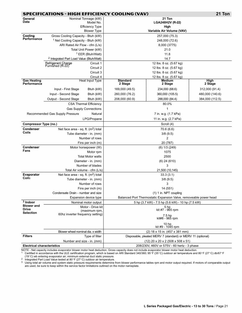
L Series Packaged Gas/Electric − 13 to 30 Tons / Page 21
SPECIFICATIONS − HIGH EFFICIENCY COOLING (VAV) 21 TonGeneralD t
Nominal Tonnage (kW) 21 TonGeneralData Model No. LGA248H2V (R−22)
Efficiency Type High
Blower Type Variable Air Volume (VAV)
CoolingP f
Gross Cooling Capacity − Btuh (kW) 257,000 (75.3)CoolingPerformance 1 Net Cooling Capacity − Btuh (kW) 248,000 (72.6)
ARI Rated Air Flow − cfm (L/s) 8,000 (3775)
Total Unit Power (kW) 21.01 EER (Btuh/Watt) 11.8
2 Integrated Part Load Value (Btuh/Watt) 14.7
Refrigerant ChargeF i h d (R 22)
Circuit 1 12 lbs. 8 oz. (5.67 kg)Refrigerant ChargeFurnished (R-22)
Circuit 2 12 lbs. 8 oz. (5.67 kg)
Circuit 3 12 lbs. 8 oz. (5.67 kg)
Circuit 4 12 lbs. 8 oz. (5.67 kg)Gas HeatingPerformance
Heat Input Type Standard2 Stage
Medium2 Stage
High2 Stage
Input − First Stage Btuh (kW) 169,000 (49.5) 234,000 (68.6) 312,000 (91.4)
Input − Second Stage Btuh (kW) 260,000 (76.2) 360,000 (105.5) 480,000 (140.6)
Output − Second Stage Btuh (kW) 208,000 (60.9) 288,000 (84.4) 384,000 (112.5)
CSA Thermal Efficiency 80.0%
Gas Supply Connections 1
Recommended Gas Supply Pressure Natural 7 in. w.g. (1.7 kPa)
LPG/Propane 11 in. w.g. (2.7 kPa)
Compressor Type (no.) Scroll (4)
Condenser Net face area − sq. ft. (m2) total 70.6 (6.6)CondenserCoils Tube diameter − in. (mm) 3/8 (9.5)
Number of rows 2
Fins per inch (m) 20 (787)
Condenser Motor horsepower (W) (6) 1/3 (249)CondenserFans Motor rpm 1075
Total Motor watts 2500
Diameter − in. (mm) (6) 24 (610)
Number of blades 3
Total Air volume − cfm (L/s) 21,500 (10,145)
Evaporator Net face area − sq. ft. (m2) total 33.3 (3.1)EvaporatorCoils Tube diameter − in. (mm) 3/8 (9.5)
Number of rows 3
Fins per inch (m) 14 (551)
Condensate Drain − number and size (1) 1 in. NPT coupling
Expansion device type Balanced Port Thermostatic Expansion Valve, removeable power head
3 Indoor Nominal motor output 5 hp (3.7 kW) − 7.5 hp (5.6 kW) − 10 hp (7.5 kW) IndoorBlower andDriveSelection
Motor − Drive kit(maximum rpm,
60hz inverter frequency setting)
5 hpkit #7 − 965 rpm
7.5 hpkit#8 − 965 rpm
10 hpkit #9 − 1045 rpm
Blower�wheel�nominal�dia.�x�width (2) 18 x 15 in. (457 x 381 mm)
Filters Type of filter Disposable, pleated MERV 7 (standard) or MERV 11 (optional)
Number and size − in. (mm) (12) 20 x 20 x 2 (508 x 508 x 51)
Electrical characteristics 208/230V, 460V or 575V − 60 hertz − 3 phase
NOTE − Net capacity includes evaporator blower motor heat deduction. Gross capacity does not include evaporator blower motor heat deduction.1 Certified in accordance with the ULE certification program, which is based on ARI Standard 340/360; 95�F (35�C) outdoor air temperature and 80�F (27�C) db/67�F
(19�C) wb entering evaporator air; minimum external duct static pressure.2 Integrated Part Load Value tested at 80�F (27�C) outdoor air temperature.3 Using total air volume and system static pressure requirements determine from blower performance tables rpm and motor output required. If motors of comparable output
are used, be sure to keep within the service factor limitations outlined on the motor nameplate.
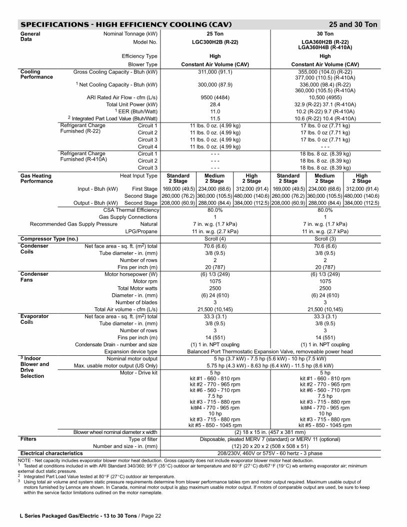
L Series Packaged Gas/Electric − 13 to 30 Tons / Page 22
SPECIFICATIONS − HIGH EFFICIENCY COOLING (CAV) 25 and 30 Ton
GeneralD t
Nominal Tonnage (kW) 25 Ton 30 TonData
Model No. LGC300H2B (R−22) LGA360H2B (R−22)LGA360H4B (R−410A)
Efficiency Type High High
Blower Type Constant Air Volume (CAV) Constant Air Volume (CAV)
CoolingPerformance
Gross Cooling Capacity − Btuh (kW) 311,000 (91.1) 355,000 (104.0) (R−22)377,000 (110.5) (R−410A)
1 Net Cooling Capacity − Btuh (kW) 300,000 (87.9) 336,000 (98.4) (R−22)360,000 (105.5) (R−410A)
ARI Rated Air Flow − cfm (L/s) 9500 (4484) 10,500 (4955)
Total Unit Power (kW) 28.4 32.9 (R−22) 37.1 (R−410A)1 EER (Btuh/Watt) 11.0 10.2 (R−22) 9.7 (R−410A)
2 Integrated Part Load Value (Btuh/Watt) 11.5 10.6 (R−22) 10.4 (R−410A)
Refrigerant ChargeF i h d (R 22)
Circuit 1 11 lbs. 0 oz. (4.99 kg) 17 lbs. 0 oz (7.71 kg)g gFurnished (R-22) Circuit 2 11 lbs. 0 oz. (4.99 kg) 17 lbs. 0 oz (7.71 kg)
Circuit 3 11 lbs. 0 oz. (4.99 kg) 17 lbs. 0 oz (7.71 kg)
Circuit 4 11 lbs. 0 oz. (4.99 kg) - - -
Refrigerant ChargeF i h d (R 410A)
Circuit 1 - - - 18 lbs. 8 oz. (8.39 kg)g gFurnished (R-410A) Circuit 2 - - - 18 lbs. 8 oz. (8.39 kg)
Circuit 3 - - - 18 lbs. 8 oz. (8.39 kg)
Gas HeatingPerformance
Heat Input Type Standard2 Stage
Medium2 Stage
High2 Stage
Standard2 Stage
Medium2 Stage
High2 Stage
Input − Btuh (kW) First Stage 169,000 (49.5) 234,000 (68.6) 312,000 (91.4) 169,000 (49.5) 234,000 (68.6) 312,000 (91.4)
Second Stage 260,000 (76.2) 360,000 (105.5) 480,000 (140.6) 260,000 (76.2) 360,000 (105.5) 480,000 (140.6)
Output − Btuh (kW) Second Stage 208,000 (60.9) 288,000 (84.4) 384,000 (112.5) 208,000 (60.9) 288,000 (84.4) 384,000 (112.5)
CSA Thermal Efficiency 80.0% 80.0%
Gas Supply Connections 1 1
Recommended Gas Supply Pressure Natural 7 in. w.g. (1.7 kPa) 7 in. w.g. (1.7 kPa)
LPG/Propane 11 in. w.g. (2.7 kPa) 11 in. w.g. (2.7 kPa)
Compressor Type (no.) Scroll (4) Scroll (3)
CondenserC il
Net face area − sq. ft. (m2) total 70.6 (6.6) 70.6 (6.6)Coils Tube diameter − in. (mm) 3/8 (9.5) 3/8 (9.5)
Number of rows 2 2
Fins per inch (m) 20 (787) 20 (787)
CondenserF
Motor horsepower (W) (6) 1/3 (249) (6) 1/3 (249)Fans Motor rpm 1075 1075
Total Motor watts 2500 2500
Diameter − in. (mm) (6) 24 (610) (6) 24 (610)
Number of blades 3 3
Total Air volume − cfm (L/s) 21,500 (10,145) 21,500 (10,145)
EvaporatorC il
Net face area − sq. ft. (m2) total 33.3 (3.1) 33.3 (3.1)pCoils Tube diameter − in. (mm) 3/8 (9.5) 3/8 (9.5)
Number of rows 3 3
Fins per inch (m) 14 (551) 14 (551)
Condensate Drain − number and size (1) 1 in. NPT coupling (1) 1 in. NPT coupling
Expansion device type Balanced Port Thermostatic Expansion Valve, removeable power head3 IndoorBl d
Nominal motor output 5 hp (3.7 kW) − 7.5 hp (5.6 kW) − 10 hp (7.5 kW)Blower andDrive
Max. usable motor output (US Only) 5.75 hp (4.3 kW) − 8.63 hp (6.4 kW) − 11.5 hp (8.6 kW)DriveSelection
Motor − Drive kit 5 hpkit #1 − 660 − 810 rpmkit #2 − 770 − 965 rpmkit #6 − 560 − 710 rpm
7.5 hpkit #3 − 715 − 880 rpmkit#4 − 770 − 965 rpm
10 hpkit #3 − 715 − 880 rpmkit #5 − 850 − 1045 rpm
5 hpkit #1 − 660 − 810 rpmkit #2 − 770 − 965 rpmkit #6 − 560 − 710 rpm
7.5 hpkit #3 − 715 − 880 rpmkit#4 − 770 − 965 rpm
10 hpkit #3 − 715 − 880 rpmkit #5 − 850 − 1045 rpm
Blower�wheel�nominal�diameter�x�width (2) 18 x 15 in. (457 x 381 mm)
Filters Type of filter Disposable, pleated MERV 7 (standard) or MERV 11 (optional)
Number and size − in. (mm) (12) 20 x 20 x 2 (508 x 508 x 51)
Electrical characteristics 208/230V, 460V or 575V − 60 hertz − 3 phase
NOTE − Net capacity includes evaporator blower motor heat deduction. Gross capacity does not include evaporator blower motor heat deduction.1 Tested at conditions included in with ARI Standard 340/360; 95�F (35�C) outdoor air temperature and 80�F (27�C) db/67�F (19�C) wb entering evaporator air; minimumexternal duct static pressure.2 Integrated Part Load Value tested at 80�F (27�C) outdoor air temperature.3 Using total air volume and system static pressure requirements determine from blower performance tables rpm and motor output required. Maximum usable output of
motors furnished by Lennox are shown. In Canada, nominal motor output is also maximum usable motor output. If motors of comparable output are used, be sure to keepwithin the service factor limitations outlined on the motor nameplate.
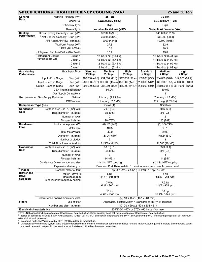
L Series Packaged Gas/Electric − 13 to 30 Tons / Page 23
SPECIFICATIONS − HIGH EFFICIENCY COOLING (VAV) 25 and 30 Ton
GeneralD t
Nominal Tonnage (kW) 25 Ton 30 TonData
Model No. LGC300H2V (R−22) LGC360H2V (R−22)
Efficiency Type High High
Blower Type Variable Air Volume (VAV) Variable Air Volume (VAV)
CoolingP f
Gross Cooling Capacity − Btuh (kW) 309,000 (90.5) 348,000 (101.9)gPerformance 1 Net Cooling Capacity − Btuh (kW) 300,000 (87.9) 336,000 (98.4)
ARI Rated Air Flow − cfm (L/s) 9000 (4245) 10,500 (4955)
Total Unit Power (kW) 27.8 32.91 EER (Btuh/Watt) 10.8 10.3
2 Integrated Part Load Value (Btuh/Watt) 13.4 13.0
Refrigerant ChargeF i h d (R 22)
Circuit 1 12 lbs. 0 oz. (5.44 kg) 12 lbs. 0 oz (5.44 kg)g gFurnished (R-22) Circuit 2 12 lbs. 0 oz. (5.44 kg) 11 lbs. 0 oz (4.99 kg)
Circuit 3 12 lbs. 0 oz. (5.44 kg) 11 lbs. 0 oz (4.99 kg)
Circuit 4 12 lbs. 0 oz. (5.44 kg) 11 lbs. 0 oz (4.99 kg)
Gas HeatingPerformance
Heat Input Type Standard2 Stage
Medium2 Stage
High2 Stage
Standard2 Stage
Medium2 Stage
High2 Stage
Input − First Stage Btuh (kW) 169,000 (49.5) 234,000 (68.6) 312,000 (91.4) 169,000 (49.5) 234,000 (68.6) 312,000 (91.4)
Input − Second Stage Btuh (kW) 260,000 (76.2) 360,000 (105.5) 480,000 (140.6) 260,000 (76.2) 360,000 (105.5) 480,000 (140.6)
Output − Second Stage Btuh (kW) 208,000 (60.9) 288,000 (84.4) 384,000 (112.5) 208,000 (60.9) 288,000 (84.4) 384,000 (112.5)
CSA Thermal Efficiency 80.0% 80.0%
Gas Supply Connections 1 1
Recommended Gas Supply Pressure Natural 7 in. w.g. (1.7 kPa) 7 in. w.g. (1.7 kPa)
LPG/Propane 11 in. w.g. (2.7 kPa) 11 in. w.g. (2.7 kPa)
Compressor Type (no.) Scroll (4) Scroll (4)
CondenserC il
Net face area − sq. ft. (m2) total 70.6 (6.6) 70.6 (6.6)Coils Tube diameter − in. (mm) 3/8 (9.5) 3/8 (9.5)
Number of rows 2 2
Fins per inch (m) 20 (787) 20 (787)
CondenserF
Motor horsepower (W) (6) 1/3 (249) (6) 1/3 (249)Fans Motor rpm 1075 1075
Total Motor watts 2500 2500
Diameter − in. (mm) (6) 24 (610) (6) 24 (610)
Number of blades 3 3
Total Air volume − cfm (L/s) 21,500 (10,145) 21,500 (10,145)
EvaporatorC il
Net face area − sq. ft. (m2) total 33.3 (3.1) 33.3 (3.1)pCoils Tube diameter − in. (mm) 3/8 (9.5) 3/8 (9.5)
Number of rows 3 3
Fins per inch (m) 14 (551) 14 (551)
Condensate Drain − number and size (1) 1 in. NPT coupling (1) 1 in. NPT coupling
Expansion device type Balanced Port Thermostatic Expansion Valve, removeable power head3 IndoorBl d
Nominal motor output 5 hp (3.7 kW) − 7.5 hp (5.6 kW) − 10 hp (7.5 kW)Blower andDriveSelection
Motor − Drive kit(maximum rpm,
60hz inverter frequency setting)
5 hpkit #7 − 965 rpm
7.5 hpkit#8 − 965 rpm
10 hpkit #9 − 1045 rpm
5 hpkit #7 − 965 rpm
7.5 hpkit#8 − 965 rpm
10 hpkit #9 − 1045 rpm
Blower�wheel�nominal�diameter�x�width (2) 18 x 15 in. (457 x 381 mm)
Filters Type of filter Disposable, pleated MERV 7 (standard) or MERV 11 (optional)
Number and size − in. (mm) (12) 20 x 20 x 2 (508 x 508 x 51)
Electrical characteristics 208/230V, 460V or 575V − 60 hertz − 3 phase
NOTE − Net capacity includes evaporator blower motor heat deduction. Gross capacity does not include evaporator blower motor heat deduction.1 Tested at conditions included in with ARI Standard 340/360; 95�F (35�C) outdoor air temperature and 80�F (27�C) db/67�F (19�C) wb entering evaporator air; minimumexternal duct static pressure.2 Integrated Part Load Value tested at 80�F (27�C) outdoor air temperature.3 Using total air volume and system static pressure requirements determine from blower performance tables rpm and motor output required. If motors of comparable output
are used, be sure to keep within the service factor limitations outlined on the motor nameplate.

L Series Packaged Gas/Electric − 13 to 30 Tons / Page 24
COOLING RATINGS
NOTE − For Temperatures and Capacities not shown in tables, see bulletin � Cooling Unit Rating Table Correction Factor Data in Miscellaneous Engineering Data section.
13 TON HIGH EFFICIENCY − LGC156H (R−22/CAV) − TWO COMPRESSORS OPERATINGOutdoor Air Temperature Entering Outdoor Coil
EnteringTotalAi
65�F (18�C) 75�F (24�C) 85�F (29�C) 95�F (35�C)EnteringWet Bulb
TotalAir
Volume TotalCooling Comp
Sensible To TotalRatio (S/T)
TotalCooling Comp
Sensible To TotalRatio (S/T)
TotalCooling Comp
Sensible To TotalRatio (S/T)
TotalCooling Comp
Sensible To TotalRatio (S/T)
Wet BulbTempera-
ture
VolumeCoolingCapacity
CompMotor
kW
Ratio (S/T)Dry Bulb
CoolingCapacity
CompMotor
kW
Ratio (S/T)Dry Bulb
CoolingCapacity
CompMotor
kW
Ratio (S/T)Dry Bulb
CoolingCapacity
CompMotor
kW
Ratio (S/T)Dry Bulbture
cfm L/s kBtuh kW
MotorkW
Input 75�F24�C
80�F27�C
85�F29�C
kBtuh kW
MotorkW
Input 75�F24�C
80�F27�C
85�F29�C
kBtuh kW
MotorkW
Input 75�F24�C
80�F27�C
85�F29�C
kBtuh kW
MotorkW
Input 75�F24�C
80�F27�C
85�F29�C
63�F4160 1965 105.6 30.9 4.67 .64 .79 .94 102.8 30.1 5.27 .64 .80 .96 99.6 29.2 5.95 .65 .82 .97 96.1 28.2 6.71 .66 .83 .99
63�F(17�C)
5200 2455 110.2 32.3 4.69 .69 .87 1.00 107.2 31.4 5.29 .70 .89 1.00 103.8 30.4 5.97 .71 .90 1.00 99.9 29.3 6.74 .73 .93 1.00(17�C)
6240 2945 113.9 33.4 4.71 .74 .94 1.00 110.7 32.4 5.31 .76 .96 1.00 107.2 31.4 5.99 .77 .98 1.00 103.5 30.3 6.75 .79 .99 1.00
67�F4160 1965 113.2 33.2 4.70 .50 .61 .74 110.0 32.2 5.30 .51 .62 .76 106.4 31.2 5.99 .51 .63 .77 102.5 30.0 6.74 .52 .64 .79
67�F(19�C)
5200 2455 117.3 34.4 4.73 .53 .66 .82 114.0 33.4 5.32 .53 .67 .84 110.1 32.3 6.00 .54 .68 .86 106.0 31.1 6.76 .55 .70 .89(19�C)
6240 2945 120.4 35.3 4.75 .55 .71 .91 116.8 34.2 5.34 .56 .73 .92 112.8 33.1 6.02 .57 .75 .94 108.5 31.8 6.78 .58 .77 .97
71�F4160 1965 121.4 35.6 4.75 .38 .48 .59 117.9 34.6 5.34 .38 .49 .59 114.1 33.4 6.02 .38 .49 .60 109.8 32.2 6.78 .38 .50 .61
71�F(22�C)
5200 2455 125.7 36.8 4.77 .39 .51 .63 121.9 35.7 5.36 .39 .52 .64 117.8 34.5 6.03 .39 .52 .65 113.3 33.2 6.80 .40 .53 .67(22�C)
6240 2945 128.7 37.7 4.79 .40 .54 .68 124.7 36.5 5.38 .40 .55 .70 120.4 35.3 6.05 .40 .55 .72 115.7 33.9 6.81 .41 .56 .74
13 TON HIGH EFFICIENCY − LGC156H (R−22/CAV) − ALL COMPRESSORS OPERATINGOutdoor Air Temperature Entering Outdoor Coil
EnteringTotalAi
85�F (29�C) 95�F (35�C) 105�F (41�C) 115�F (46�C)EnteringWet Bulb
TotalAir
Volume TotalCooling Comp
Sensible To TotalRatio (S/T)
TotalCooling Comp
Sensible To TotalRatio (S/T)
TotalCooling Comp
Sensible To TotalRatio (S/T)
TotalCooling Comp
Sensible To TotalRatio (S/T)
Wet BulbTempera-
ture
VolumeCoolingCapacity
CompMotor
kW
Ratio (S/T)Dry Bulb
CoolingCapacity
CompMotor
kW
Ratio (S/T)Dry Bulb
CoolingCapacity
CompMotor
kW
Ratio (S/T)Dry Bulb
CoolingCapacity
CompMotor
kW
Ratio (S/T)Dry Bulbture
cfm L/s kBtuh kW
MotorkW
Input 75�F24�C
80�F27�C
85�F29�C
kBtuh kW
MotorkW
Input 75�F24�C
80�F27�C
85�F29�C
kBtuh kW
MotorkW
Input 75�F24�C
80�F27�C
85�F29�C
kBtuh kW
MotorkW
Input 75�F24�C
80�F27�C
85�F29�C
63�F4160 1965 150.4 44.1 9.03 .68 .84 .98 145.1 42.5 10.18 .69 .85 1.00 139.2 40.8 11.51 .70 .87 1.00 132.9 38.9 12.98 .72 .90 1.00
63�F(17�C)
5200 2455 156.7 45.9 9.06 .74 .92 1.00 150.9 44.2 10.22 .75 .94 1.00 144.8 42.4 11.54 .77 .96 1.00 138.5 40.6 13.01 .79 .99 1.00(17�C)
6240 2945 161.9 47.4 9.09 .80 .99 1.00 156.3 45.8 10.25 .82 1.00 1.00 150.7 44.2 11.54 .84 1.00 1.00 144.5 42.3 13.02 .87 1.00 1.00
67�F4160 1965 160.7 47.1 9.09 .53 .66 .79 154.8 45.4 10.24 .54 .67 .81 148.5 43.5 11.54 .55 .68 .83 141.6 41.5 13.01 .56 .70 .86
67�F(19�C)
5200 2455 166.2 48.7 9.12 .56 .71 .88 160.0 46.9 10.26 .57 .72 .90 153.3 44.9 11.58 .58 .74 .93 145.9 42.8 13.05 .59 .77 .95(19�C)
6240 2945 170.2 49.9 9.14 .59 .77 .96 163.7 48.0 10.29 .60 .79 .98 156.6 45.9 11.60 .62 .81 1.00 149.2 43.7 13.07 .63 .84 1.00
71�F4160 1965 172.2 50.5 9.15 .40 .52 .63 165.8 48.6 10.29 .40 .52 .64 159.0 46.6 11.59 .41 .53 .66 151.7 44.5 13.07 .41 .54 .67
71�F(22�C)
5200 2455 177.8 52.1 9.17 .41 .55 .69 171.0 50.1 10.32 .41 .56 .70 163.6 47.9 11.64 .42 .57 .72 155.8 45.7 13.10 .42 .58 .74(22�C)
6240 2945 181.6 53.2 9.19 .42 .58 .74 174.6 51.2 10.34 .43 .59 .76 166.9 48.9 11.64 .43 .60 .79 158.7 46.5 13.12 .44 .62 .81
15 TON STANDARD EFFICIENCY − LGC180S (R−22/CAV) − TWO COMPRESSORS OPERATINGOutdoor Air Temperature Entering Outdoor Coil
EnteringTotalAi
65�F (18�C) 75�F (24�C) 85�F (29�C) 95�F (35�C)EnteringWet Bulb
TotalAir
Volume TotalCooling Comp
Sensible To TotalRatio (S/T)
TotalCooling Comp
Sensible To TotalRatio (S/T)
TotalCooling Comp
Sensible To TotalRatio (S/T)
TotalCooling Comp
Sensible To TotalRatio (S/T)
Wet BulbTempera-
ture
VolumeCoolingCapacity
CompMotor
kW
Ratio (S/T)Dry Bulb
CoolingCapacity
CompMotor
kW
Ratio (S/T)Dry Bulb
CoolingCapacity
CompMotor
kW
Ratio (S/T)Dry Bulb
CoolingCapacity
CompMotor
kW
Ratio (S/T)Dry Bulbture
cfm L/s kBtuh kW
MotorkW
Input 75�F24�C
80�F27�C
85�F29�C
kBtuh kW
MotorkW
Input 75�F24�C
80�F27�C
85�F29�C
kBtuh kW
MotorkW
Input 75�F24�C
80�F27�C
85�F29�C
kBtuh kW
MotorkW
Input 75�F24�C
80�F27�C
85�F29�C
63�F4800 2265 123.4 36.2 7.02 .66 .80 .94 120.2 35.2 7.72 .67 .81 .95 116.3 34.1 8.52 .68 .83 .97 112.1 32.9 9.45 .69 .85 .98
63�F(17�C)
6000 2830 128.2 37.6 7.13 .71 .88 1.00 124.8 36.6 7.82 .72 .89 1.00 120.8 35.4 8.62 .73 .91 1.00 116.5 34.1 9.55 .75 .93 1.00(17�C)
7200 3400 132.0 38.7 7.20 .77 .94 1.00 128.5 37.7 7.90 .78 .96 1.00 124.5 36.5 8.71 .79 .97 1.00 120.2 35.2 9.63 .81 .99 1.00
67�F4800 2265 131.2 38.5 7.18 .53 .64 .77 127.7 37.4 7.88 .53 .65 .78 123.7 36.3 8.69 .53 .65 .79 119.2 34.9 9.61 .54 .66 .81
67�F(19�C)
6000 2830 135.4 39.7 7.28 .55 .69 .84 131.8 38.6 7.98 .55 .69 .86 127.6 37.4 8.78 .56 .71 .87 123.0 36.0 9.71 .57 .72 .89(19�C)
7200 3400 138.3 40.5 7.34 .58 .74 .91 134.7 39.5 8.04 .58 .75 .93 130.4 38.2 8.85 .59 .77 .95 125.6 36.8 9.79 .60 .79 .96
71�F4800 2265 139.5 40.9 7.36 .40 .51 .62 136.0 39.9 8.06 .40 .51 .62 131.8 38.6 8.87 .40 .52 .63 127.1 37.2 9.82 .40 .52 .64
71�F(22�C)
6000 2830 143.7 42.1 7.46 .41 .54 .66 140.0 41.0 8.16 .41 .54 .67 135.6 39.7 8.97 .41 .55 .68 130.8 38.3 9.90 .41 .55 .70(22�C)
7200 3400 146.5 42.9 7.53 .42 .57 .72 142.8 41.9 8.22 .42 .57 .73 138.2 40.5 9.03 .42 .58 .74 133.1 39.0 9.98 .43 .59 .76
15 TON STANDARD EFFICIENCY − LGC180S (R−22/CAV) − ALL COMPRESSORS OPERATINGOutdoor Air Temperature Entering Outdoor Coil
EnteringTotalAi
85�F (29�C) 95�F (35�C) 105�F (41�C) 115�F (46�C)EnteringWet Bulb
TotalAir
Volume TotalCooling Comp
Sensible To TotalRatio (S/T)
TotalCooling Comp
Sensible To TotalRatio (S/T)
TotalCooling Comp
Sensible To TotalRatio (S/T)
TotalCooling Comp
Sensible To TotalRatio (S/T)
Wet BulbTempera-
ture
VolumeCoolingCapacity
CompMotor
kW
Ratio (S/T)Dry Bulb
CoolingCapacity
CompMotor
kW
Ratio (S/T)Dry Bulb
CoolingCapacity
CompMotor
kW
Ratio (S/T)Dry Bulb
CoolingCapacity
CompMotor
kW
Ratio (S/T)Dry Bulbture
cfm L/s kBtuh kW
MotorkW
Input 75�F24�C
80�F27�C
85�F29�C
kBtuh kW
MotorkW
Input 75�F24�C
80�F27�C
85�F29�C
kBtuh kW
MotorkW
Input 75�F24�C
80�F27�C
85�F29�C
kBtuh kW
MotorkW
Input 75�F24�C
80�F27�C
85�F29�C
63�F4800 2265 176.3 51.7 12.81 .69 .84 .97 169.9 49.8 14.20 .70 .85 .98 163.3 47.9 15.75 .71 .87 1.00 156.8 46.0 17.52 .73 .89 1.00
63�F(17�C)
6000 2830 183.2 53.7 12.96 .74 .91 1.00 176.6 51.8 14.35 .76 .93 1.00 169.6 49.7 15.93 .78 .95 1.00 162.9 47.7 17.73 .79 .97 1.00(17�C)
7200 3400 188.8 55.3 13.09 .80 .97 1.00 182.2 53.4 14.48 .82 .99 1.00 175.5 51.4 16.08 .84 1.00 1.00 169.1 49.6 17.91 .86 1.00 1.00
67�F4800 2265 187.6 55.0 13.06 .54 .67 .80 180.7 53.0 14.45 .55 .68 .82 173.6 50.9 16.05 .56 .69 .83 166.5 48.8 17.83 .56 .70 .85
67�F(19�C)
6000 2830 193.5 56.7 13.20 .57 .72 .88 186.4 54.6 14.60 .58 .73 .90 178.8 52.4 16.19 .59 .75 .92 171.4 50.2 18.01 .60 .77 .94(19�C)
7200 3400 197.7 57.9 13.31 .60 .78 .95 190.4 55.8 14.72 .61 .80 .97 182.6 53.5 16.31 .62 .82 .98 174.8 51.2 18.11 .64 .84 1.00
71�F4800 2265 199.8 58.6 13.34 .41 .53 .64 192.6 56.4 14.76 .41 .53 .66 185.1 54.2 16.37 .41 .54 .67 177.5 52.0 18.18 .42 .55 .68
71�F(22�C)
6000 2830 205.6 60.3 13.49 .42 .56 .70 198.2 58.1 14.89 .42 .57 .71 190.3 55.8 16.51 .43 .58 .73 182.1 53.4 18.36 .43 .59 .74(22�C)
7200 3400 209.5 61.4 13.58 .43 .59 .75 201.8 59.1 15.01 .43 .60 .77 193.8 56.8 16.61 .44 .61 .79 185.3 54.3 18.45 .44 .63 .81

L Series Packaged Gas/Electric − 13 to 30 Tons / Page 25
COOLING RATINGS
NOTE − For Temperatures and Capacities not shown in tables, see bulletin � Cooling Unit Rating Table Correction Factor Data in Miscellaneous Engineering Data section.
15 TON HIGH EFFICIENCY − LGC180H (R−22/CAV) − TWO COMPRESSORS OPERATINGOutdoor Air Temperature Entering Outdoor Coil
EnteringTotalAi
65�F (18�C) 75�F (24�C) 85�F (29�C) 95�F (35�C)EnteringWet Bulb
TotalAir
Volume TotalCooling Comp
Sensible To TotalRatio (S/T)
TotalCooling Comp
Sensible To TotalRatio (S/T)
TotalCooling Comp
Sensible To TotalRatio (S/T)
TotalCooling Comp
Sensible To TotalRatio (S/T)
Wet BulbTempera-
ture
VolumeCoolingCapacity
CompMotor
kW
Ratio (S/T)Dry Bulb
CoolingCapacity
CompMotor
kW
Ratio (S/T)Dry Bulb
CoolingCapacity
CompMotor
kW
Ratio (S/T)Dry Bulb
CoolingCapacity
CompMotor
kW
Ratio (S/T)Dry Bulbture
cfm L/s kBtuh kW
MotorkW
Input 75�F24�C
80�F27�C
85�F29�C
kBtuh kW
MotorkW
Input 75�F24�C
80�F27�C
85�F29�C
kBtuh kW
MotorkW
Input 75�F24�C
80�F27�C
85�F29�C
kBtuh kW
MotorkW
Input 75�F24�C
80�F27�C
85�F29�C
63�F4800 2265 128.6 37.7 5.78 .66 .80 .93 125.2 36.7 6.47 .67 .81 .94 121.4 35.6 7.29 .67 .82 .96 117.2 34.3 8.22 .68 .84 .97
63�F(17�C)
6000 2830 133.8 39.2 5.82 .71 .87 .99 130.0 38.1 6.52 .72 .88 1.00 126.1 37.0 7.32 .73 .90 1.00 121.8 35.7 8.26 .74 .91 1.00(17�C)
7200 3400 137.6 40.3 5.85 .76 .93 1.00 133.9 39.2 6.54 .77 .95 1.00 129.9 38.1 7.36 .78 .96 1.00 125.4 36.8 8.29 .80 .98 1.00
67�F4800 2265 137.0 40.2 5.84 .52 .64 .76 133.3 39.1 6.53 .53 .64 .77 129.1 37.8 7.35 .53 .65 .78 124.7 36.5 8.30 .54 .66 .80
67�F(19�C)
6000 2830 141.7 41.5 5.87 .55 .68 .83 137.7 40.4 6.58 .55 .69 .84 133.3 39.1 7.39 .56 .70 .86 128.6 37.7 8.32 .57 .72 .88(19�C)
7200 3400 145.1 42.5 5.91 .57 .73 .90 140.9 41.3 6.61 .58 .74 .91 136.3 39.9 7.41 .59 .76 .93 131.4 38.5 8.35 .60 .78 .95
71�F4800 2265 146.2 42.8 5.91 .40 .51 .61 142.0 41.6 6.61 .40 .51 .62 137.7 40.4 7.42 .40 .51 .63 132.9 38.9 8.37 .40 .52 .64
71�F(22�C)
6000 2830 150.9 44.2 5.95 .41 .53 .66 146.5 42.9 6.65 .41 .54 .67 141.8 41.6 7.46 .41 .54 .68 136.8 40.1 8.40 .41 .55 .69(22�C)
7200 3400 154.1 45.2 5.98 .42 .56 .71 149.6 43.8 6.68 .42 .57 .72 144.8 42.4 7.48 .42 .57 .73 139.6 40.9 8.43 .42 .58 .75
15 TON HIGH EFFICIENCY − LGC180H (R−22/CAV) − ALL COMPRESSORS OPERATINGOutdoor Air Temperature Entering Outdoor Coil
EnteringTotalAi
85�F (29�C) 95�F (35�C) 105�F (41�C) 115�F (46�C)EnteringWet Bulb
TotalAir
Volume TotalCooling Comp
Sensible To TotalRatio (S/T)
TotalCooling Comp
Sensible To TotalRatio (S/T)
TotalCooling Comp
Sensible To TotalRatio (S/T)
TotalCooling Comp
Sensible To TotalRatio (S/T)
Wet BulbTempera-
ture
VolumeCoolingCapacity
CompMotor
kW
Ratio (S/T)Dry Bulb
CoolingCapacity
CompMotor
kW
Ratio (S/T)Dry Bulb
CoolingCapacity
CompMotor
kW
Ratio (S/T)Dry Bulb
CoolingCapacity
CompMotor
kW
Ratio (S/T)Dry Bulbture
cfm L/s kBtuh kW
MotorkW
Input 75�F24�C
80�F27�C
85�F29�C
kBtuh kW
MotorkW
Input 75�F24�C
80�F27�C
85�F29�C
kBtuh kW
MotorkW
Input 75�F24�C
80�F27�C
85�F29�C
kBtuh kW
MotorkW
Input 75�F24�C
80�F27�C
85�F29�C
63�F4800 2265 177.6 52.0 10.86 .69 .82 .96 171.5 50.3 12.26 .69 .84 .97 165.1 48.4 13.86 .70 .85 .99 158.3 46.4 15.67 .72 .88 1.00
63�F(17�C)
6000 2830 184.4 54.0 10.92 .73 .90 1.00 178.1 52.2 12.31 .75 .92 1.00 171.4 50.2 13.91 .76 .93 1.00 164.3 48.2 15.75 .78 .96 1.00(17�C)
7200 3400 189.9 55.7 10.96 .79 .96 1.00 183.6 53.8 12.36 .80 .98 1.00 176.9 51.8 13.97 .82 .99 1.00 170.3 49.9 15.78 .84 1.00 1.00
67�F4800 2265 188.9 55.4 10.96 .54 .66 .79 182.3 53.4 12.36 .54 .67 .80 175.4 51.4 13.97 .55 .68 .82 168.2 49.3 15.78 .56 .69 .84
67�F(19�C)
6000 2830 195.0 57.1 11.02 .57 .71 .86 188.1 55.1 12.40 .57 .72 .88 180.9 53.0 14.00 .58 .74 .90 173.2 50.8 15.84 .59 .76 .92(19�C)
7200 3400 199.5 58.5 11.05 .60 .76 .93 192.3 56.4 12.46 .60 .78 .95 184.8 54.2 14.06 .61 .80 .97 176.8 51.8 15.90 .63 .82 .99
71�F4800 2265 201.4 59.0 11.06 .41 .52 .64 194.5 57.0 12.47 .41 .53 .64 187.0 54.8 14.09 .41 .53 .66 179.4 52.6 15.91 .41 .54 .67
71�F(22�C)
6000 2830 207.6 60.8 11.13 .42 .55 .69 200.2 58.7 12.52 .42 .56 .70 192.5 56.4 14.13 .42 .57 .71 184.4 54.0 15.96 .43 .58 .73(22�C)
7200 3400 211.8 62.1 11.17 .43 .58 .74 204.1 59.8 12.56 .43 .59 .76 196.0 57.4 14.19 .44 .60 .78 187.6 55.0 16.01 .44 .62 .80
15 TON HIGH EFFICIENCY − LGC180H (R−410A/CAV) − TWO COMPRESSORS OPERATINGOutdoor Air Temperature Entering Outdoor Coil
EnteringTotalAi
65�F (18�C) 75�F (24�C) 85�F (29�C) 95�F (35�C)EnteringWet Bulb
TotalAir
Volume TotalCooling Comp
Sensible To TotalRatio (S/T)
TotalCooling Comp
Sensible To TotalRatio (S/T)
TotalCooling Comp
Sensible To TotalRatio (S/T)
TotalCooling Comp
Sensible To TotalRatio (S/T)
Wet BulbTempera-
ture
VolumeCoolingCapacity
CompMotor
kW
Ratio (S/T)Dry Bulb
CoolingCapacity
CompMotor
kW
Ratio (S/T)Dry Bulb
CoolingCapacity
CompMotor
kW
Ratio (S/T)Dry Bulb
CoolingCapacity
CompMotor
kW
Ratio (S/T)Dry Bulbture
cfm L/s kBtuh kW
MotorkW
Input 75�F24�C
80�F27�C
85�F29�C
kBtuh kW
MotorkW
Input 75�F24�C
80�F27�C
85�F29�C
kBtuh kW
MotorkW
Input 75�F24�C
80�F27�C
85�F29�C
kBtuh kW
MotorkW
Input 75�F24�C
80�F27�C
85�F29�C
63�F4800 2265 131.6 38.6 5.75 .68 .80 .92 126.8 37.2 6.57 .69 .82 .94 121.7 35.7 7.51 .70 .83 .95 116.3 34.1 8.57 .71 .85 .97
63�F(17�C)
6000 2830 137.0 40.2 5.77 .72 .86 .98 131.9 38.7 6.61 .73 .88 .99 126.6 37.1 7.54 .75 .90 1.00 120.9 35.4 8.60 .76 .92 1.00(17�C)
7200 3400 141.2 41.4 5.79 .77 .92 1.00 135.9 39.8 6.63 .78 .94 1.00 130.5 38.2 7.56 .80 .96 1.00 124.7 36.5 8.63 .82 .98 1.00
67�F4800 2265 140.4 41.1 5.79 .54 .65 .77 135.2 39.6 6.62 .55 .66 .78 129.7 38.0 7.56 .55 .67 .80 123.9 36.3 8.63 .56 .69 .82
67�F(19�C)
6000 2830 145.5 42.6 5.81 .56 .70 .83 139.9 41.0 6.65 .57 .71 .85 134.1 39.3 7.60 .58 .72 .87 127.9 37.5 8.66 .59 .74 .89(19�C)
7200 3400 149.0 43.7 5.83 .59 .74 .89 143.2 42.0 6.68 .60 .76 .91 137.2 40.2 7.62 .61 .78 .93 130.8 38.3 8.68 .62 .79 .95
71�F4800 2265 149.8 43.9 5.83 .42 .52 .63 144.3 42.3 6.68 .42 .53 .64 138.5 40.6 7.62 .42 .53 .65 132.2 38.7 8.69 .42 .54 .66
71�F(22�C)
6000 2830 155.0 45.4 5.85 .42 .55 .67 149.1 43.7 6.71 .42 .55 .68 142.8 41.9 7.66 .43 .56 .70 136.2 39.9 8.73 .43 .57 .72(22�C)
7200 3400 158.6 46.5 5.87 .43 .57 .72 152.3 44.6 6.74 .43 .58 .73 145.8 42.7 7.69 .44 .59 .75 139.0 40.7 8.75 .44 .61 .77
15 TON HIGH EFFICIENCY − LGC180H (R−410A/CAV) − ALL COMPRESSORS OPERATINGOutdoor Air Temperature Entering Outdoor Coil
EnteringTotalAi
85�F (29�C) 95�F (35�C) 105�F (41�C) 115�F (46�C)EnteringWet Bulb
TotalAir
Volume TotalCooling Comp
Sensible To TotalRatio (S/T)
TotalCooling Comp
Sensible To TotalRatio (S/T)
TotalCooling Comp
Sensible To TotalRatio (S/T)
TotalCooling Comp
Sensible To TotalRatio (S/T)
Wet BulbTempera-
ture
VolumeCoolingCapacity
CompMotor
kW
Ratio (S/T)Dry Bulb
CoolingCapacity
CompMotor
kW
Ratio (S/T)Dry Bulb
CoolingCapacity
CompMotor
kW
Ratio (S/T)Dry Bulb
CoolingCapacity
CompMotor
kW
Ratio (S/T)Dry Bulbture
cfm L/s kBtuh kW
MotorkW
Input 75�F24�C
80�F27�C
85�F29�C
kBtuh kW
MotorkW
Input 75�F24�C
80�F27�C
85�F29�C
kBtuh kW
MotorkW
Input 75�F24�C
80�F27�C
85�F29�C
kBtuh kW
MotorkW
Input 75�F24�C
80�F27�C
85�F29�C
63�F4800 2265 182.2 53.4 11.30 .70 .83 .95 174.1 51.0 12.89 .71 .85 .97 165.4 48.5 14.68 .73 .87 .99 155.8 45.7 16.68 .74 .90 1.00
63�F(17�C)
6000 2830 189.5 55.5 11.35 .75 .90 1.00 181.0 53.0 12.94 .76 .92 1.00 171.8 50.3 14.72 .78 .94 1.00 161.9 47.4 16.74 .81 .97 1.00(17�C)
7200 3400 195.4 57.3 11.38 .80 .96 1.00 186.7 54.7 12.98 .81 .98 1.00 177.5 52.0 14.76 .84 .99 1.00 168.3 49.3 16.75 .87 1.00 1.00
67�F4800 2265 194.2 56.9 11.38 .55 .67 .80 185.5 54.4 12.99 .56 .68 .81 176.1 51.6 14.76 .57 .70 .83 165.8 48.6 16.76 .58 .72 .86
67�F(19�C)
6000 2830 200.8 58.8 11.44 .58 .72 .86 191.5 56.1 13.03 .59 .74 .89 181.6 53.2 14.81 .60 .76 .91 170.6 50.0 16.82 .61 .78 .94(19�C)
7200 3400 205.4 60.2 11.47 .61 .77 .93 195.9 57.4 13.06 .62 .79 .95 185.5 54.4 14.86 .63 .82 .97 174.4 51.1 16.84 .65 .84 .99
71�F4800 2265 207.3 60.8 11.47 .42 .53 .65 197.9 58.0 13.08 .42 .54 .66 188.0 55.1 14.88 .42 .55 .67 177.1 51.9 16.85 .43 .56 .69
71�F(22�C)
6000 2830 213.8 62.7 11.53 .43 .56 .70 203.9 59.8 13.14 .43 .57 .71 193.4 56.7 14.91 .43 .58 .73 181.8 53.3 16.91 .44 .60 .76(22�C)
7200 3400 218.3 64.0 11.58 .44 .59 .75 208.1 61.0 13.17 .44 .61 .77 196.9 57.7 14.97 .45 .62 .79 185.1 54.2 16.93 .45 .64 .82
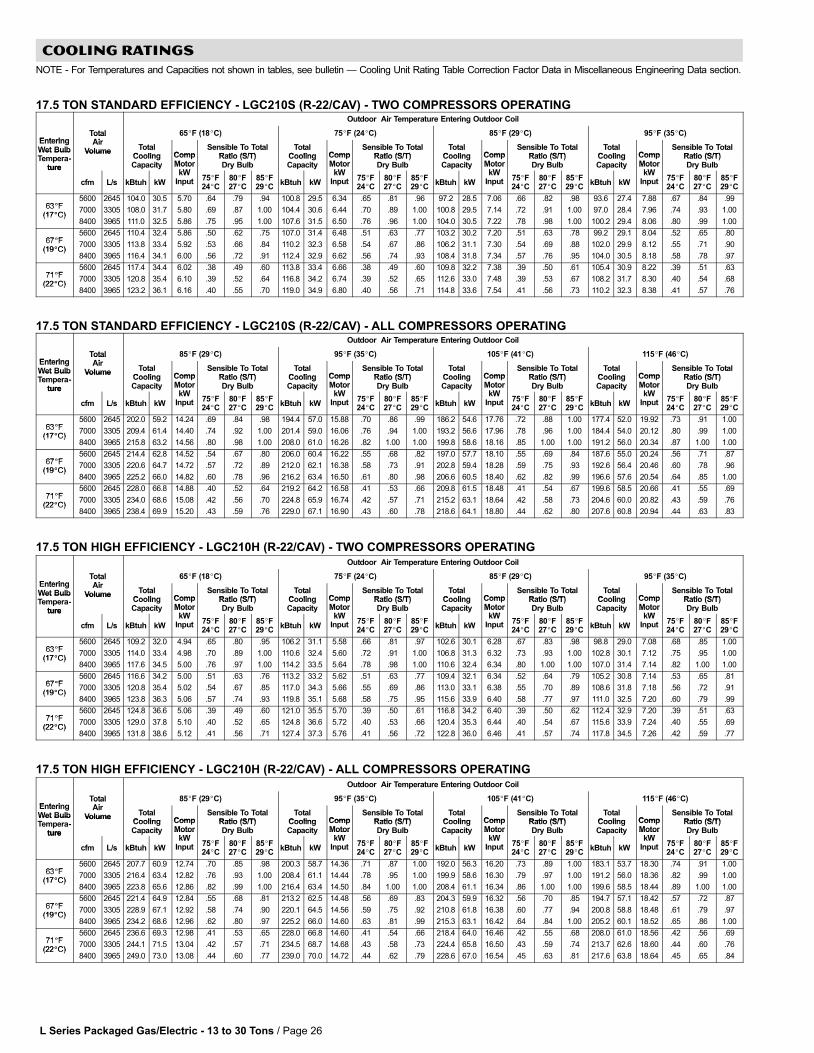
L Series Packaged Gas/Electric − 13 to 30 Tons / Page 26
COOLING RATINGS
NOTE − For Temperatures and Capacities not shown in tables, see bulletin � Cooling Unit Rating Table Correction Factor Data in Miscellaneous Engineering Data section.
17.5 TON STANDARD EFFICIENCY − LGC210S (R−22/CAV) − TWO COMPRESSORS OPERATINGOutdoor Air Temperature Entering Outdoor Coil
EnteringTotalAi
65�F (18�C) 75�F (24�C) 85�F (29�C) 95�F (35�C)EnteringWet Bulb
TotalAir
Volume TotalCooling Comp
Sensible To TotalRatio (S/T)
TotalCooling Comp
Sensible To TotalRatio (S/T)
TotalCooling Comp
Sensible To TotalRatio (S/T)
TotalCooling Comp
Sensible To TotalRatio (S/T)
Wet BulbTempera-
ture
VolumeCoolingCapacity
CompMotor
kW
Ratio (S/T)Dry Bulb
CoolingCapacity
CompMotor
kW
Ratio (S/T)Dry Bulb
CoolingCapacity
CompMotor
kW
Ratio (S/T)Dry Bulb
CoolingCapacity
CompMotor
kW
Ratio (S/T)Dry Bulbture
cfm L/s kBtuh kW
MotorkW
Input 75�F24�C
80�F27�C
85�F29�C
kBtuh kW
MotorkW
Input 75�F24�C
80�F27�C
85�F29�C
kBtuh kW
MotorkW
Input 75�F24�C
80�F27�C
85�F29�C
kBtuh kW
MotorkW
Input 75�F24�C
80�F27�C
85�F29�C
63�F5600 2645 104.0 30.5 5.70 .64 .79 .94 100.8 29.5 6.34 .65 .81 .96 97.2 28.5 7.06 .66 .82 .98 93.6 27.4 7.88 .67 .84 .99
63�F(17�C)
7000 3305 108.0 31.7 5.80 .69 .87 1.00 104.4 30.6 6.44 .70 .89 1.00 100.8 29.5 7.14 .72 .91 1.00 97.0 28.4 7.96 .74 .93 1.00(17�C)
8400 3965 111.0 32.5 5.86 .75 .95 1.00 107.6 31.5 6.50 .76 .96 1.00 104.0 30.5 7.22 .78 .98 1.00 100.2 29.4 8.06 .80 .99 1.00
67�F5600 2645 110.4 32.4 5.86 .50 .62 .75 107.0 31.4 6.48 .51 .63 .77 103.2 30.2 7.20 .51 .63 .78 99.2 29.1 8.04 .52 .65 .80
67�F(19�C)
7000 3305 113.8 33.4 5.92 .53 .66 .84 110.2 32.3 6.58 .54 .67 .86 106.2 31.1 7.30 .54 .69 .88 102.0 29.9 8.12 .55 .71 .90(19�C)
8400 3965 116.4 34.1 6.00 .56 .72 .91 112.4 32.9 6.62 .56 .74 .93 108.4 31.8 7.34 .57 .76 .95 104.0 30.5 8.18 .58 .78 .97
71�F5600 2645 117.4 34.4 6.02 .38 .49 .60 113.8 33.4 6.66 .38 .49 .60 109.8 32.2 7.38 .39 .50 .61 105.4 30.9 8.22 .39 .51 .63
71�F(22�C)
7000 3305 120.8 35.4 6.10 .39 .52 .64 116.8 34.2 6.74 .39 .52 .65 112.6 33.0 7.48 .39 .53 .67 108.2 31.7 8.30 .40 .54 .68(22�C)
8400 3965 123.2 36.1 6.16 .40 .55 .70 119.0 34.9 6.80 .40 .56 .71 114.8 33.6 7.54 .41 .56 .73 110.2 32.3 8.38 .41 .57 .76
17.5 TON STANDARD EFFICIENCY − LGC210S (R−22/CAV) − ALL COMPRESSORS OPERATINGOutdoor Air Temperature Entering Outdoor Coil
EnteringTotalAi
85�F (29�C) 95�F (35�C) 105�F (41�C) 115�F (46�C)EnteringWet Bulb
TotalAir
Volume TotalCooling Comp
Sensible To TotalRatio (S/T)
TotalCooling Comp
Sensible To TotalRatio (S/T)
TotalCooling Comp
Sensible To TotalRatio (S/T)
TotalCooling Comp
Sensible To TotalRatio (S/T)
Wet BulbTempera-
ture
VolumeCoolingCapacity
CompMotor
kW
Ratio (S/T)Dry Bulb
CoolingCapacity
CompMotor
kW
Ratio (S/T)Dry Bulb
CoolingCapacity
CompMotor
kW
Ratio (S/T)Dry Bulb
CoolingCapacity
CompMotor
kW
Ratio (S/T)Dry Bulbture
cfm L/s kBtuh kW
MotorkW
Input 75�F24�C
80�F27�C
85�F29�C
kBtuh kW
MotorkW
Input 75�F24�C
80�F27�C
85�F29�C
kBtuh kW
MotorkW
Input 75�F24�C
80�F27�C
85�F29�C
kBtuh kW
MotorkW
Input 75�F24�C
80�F27�C
85�F29�C
63�F5600 2645 202.0 59.2 14.24 .69 .84 .98 194.4 57.0 15.88 .70 .86 .99 186.2 54.6 17.76 .72 .88 1.00 177.4 52.0 19.92 .73 .91 1.00
63�F(17�C)
7000 3305 209.4 61.4 14.40 .74 .92 1.00 201.4 59.0 16.06 .76 .94 1.00 193.2 56.6 17.96 .78 .96 1.00 184.4 54.0 20.12 .80 .99 1.00(17�C)
8400 3965 215.8 63.2 14.56 .80 .98 1.00 208.0 61.0 16.26 .82 1.00 1.00 199.8 58.6 18.16 .85 1.00 1.00 191.2 56.0 20.34 .87 1.00 1.00
67�F5600 2645 214.4 62.8 14.52 .54 .67 .80 206.0 60.4 16.22 .55 .68 .82 197.0 57.7 18.10 .55 .69 .84 187.6 55.0 20.24 .56 .71 .87
67�F(19�C)
7000 3305 220.6 64.7 14.72 .57 .72 .89 212.0 62.1 16.38 .58 .73 .91 202.8 59.4 18.28 .59 .75 .93 192.6 56.4 20.46 .60 .78 .96(19�C)
8400 3965 225.2 66.0 14.82 .60 .78 .96 216.2 63.4 16.50 .61 .80 .98 206.6 60.5 18.40 .62 .82 .99 196.6 57.6 20.54 .64 .85 1.00
71�F5600 2645 228.0 66.8 14.88 .40 .52 .64 219.2 64.2 16.58 .41 .53 .66 209.8 61.5 18.48 .41 .54 .67 199.6 58.5 20.66 .41 .55 .69
71�F(22�C)
7000 3305 234.0 68.6 15.08 .42 .56 .70 224.8 65.9 16.74 .42 .57 .71 215.2 63.1 18.64 .42 .58 .73 204.6 60.0 20.82 .43 .59 .76(22�C)
8400 3965 238.4 69.9 15.20 .43 .59 .76 229.0 67.1 16.90 .43 .60 .78 218.6 64.1 18.80 .44 .62 .80 207.6 60.8 20.94 .44 .63 .83
17.5 TON HIGH EFFICIENCY − LGC210H (R−22/CAV) − TWO COMPRESSORS OPERATINGOutdoor Air Temperature Entering Outdoor Coil
EnteringTotalAi
65�F (18�C) 75�F (24�C) 85�F (29�C) 95�F (35�C)EnteringWet Bulb
TotalAir
Volume TotalCooling Comp
Sensible To TotalRatio (S/T)
TotalCooling Comp
Sensible To TotalRatio (S/T)
TotalCooling Comp
Sensible To TotalRatio (S/T)
TotalCooling Comp
Sensible To TotalRatio (S/T)
Wet BulbTempera-
ture
VolumeCoolingCapacity
CompMotor
kW
Ratio (S/T)Dry Bulb
CoolingCapacity
CompMotor
kW
Ratio (S/T)Dry Bulb
CoolingCapacity
CompMotor
kW
Ratio (S/T)Dry Bulb
CoolingCapacity
CompMotor
kW
Ratio (S/T)Dry Bulbture
cfm L/s kBtuh kW
MotorkW
Input 75�F24�C
80�F27�C
85�F29�C
kBtuh kW
MotorkW
Input 75�F24�C
80�F27�C
85�F29�C
kBtuh kW
MotorkW
Input 75�F24�C
80�F27�C
85�F29�C
kBtuh kW
MotorkW
Input 75�F24�C
80�F27�C
85�F29�C
63�F5600 2645 109.2 32.0 4.94 .65 .80 .95 106.2 31.1 5.58 .66 .81 .97 102.6 30.1 6.28 .67 .83 .98 98.8 29.0 7.08 .68 .85 1.00
63�F(17�C)
7000 3305 114.0 33.4 4.98 .70 .89 1.00 110.6 32.4 5.60 .72 .91 1.00 106.8 31.3 6.32 .73 .93 1.00 102.8 30.1 7.12 .75 .95 1.00(17�C)
8400 3965 117.6 34.5 5.00 .76 .97 1.00 114.2 33.5 5.64 .78 .98 1.00 110.6 32.4 6.34 .80 1.00 1.00 107.0 31.4 7.14 .82 1.00 1.00
67�F5600 2645 116.6 34.2 5.00 .51 .63 .76 113.2 33.2 5.62 .51 .63 .77 109.4 32.1 6.34 .52 .64 .79 105.2 30.8 7.14 .53 .65 .81
67�F(19�C)
7000 3305 120.8 35.4 5.02 .54 .67 .85 117.0 34.3 5.66 .55 .69 .86 113.0 33.1 6.38 .55 .70 .89 108.6 31.8 7.18 .56 .72 .91(19�C)
8400 3965 123.8 36.3 5.06 .57 .74 .93 119.8 35.1 5.68 .58 .75 .95 115.6 33.9 6.40 .58 .77 .97 111.0 32.5 7.20 .60 .79 .99
71�F5600 2645 124.8 36.6 5.06 .39 .49 .60 121.0 35.5 5.70 .39 .50 .61 116.8 34.2 6.40 .39 .50 .62 112.4 32.9 7.20 .39 .51 .63
71�F(22�C)
7000 3305 129.0 37.8 5.10 .40 .52 .65 124.8 36.6 5.72 .40 .53 .66 120.4 35.3 6.44 .40 .54 .67 115.6 33.9 7.24 .40 .55 .69(22�C)
8400 3965 131.8 38.6 5.12 .41 .56 .71 127.4 37.3 5.76 .41 .56 .72 122.8 36.0 6.46 .41 .57 .74 117.8 34.5 7.26 .42 .59 .77
17.5 TON HIGH EFFICIENCY − LGC210H (R−22/CAV) − ALL COMPRESSORS OPERATINGOutdoor Air Temperature Entering Outdoor Coil
EnteringTotalAi
85�F (29�C) 95�F (35�C) 105�F (41�C) 115�F (46�C)EnteringWet Bulb
TotalAir
Volume TotalCooling Comp
Sensible To TotalRatio (S/T)
TotalCooling Comp
Sensible To TotalRatio (S/T)
TotalCooling Comp
Sensible To TotalRatio (S/T)
TotalCooling Comp
Sensible To TotalRatio (S/T)
Wet BulbTempera-
ture
VolumeCoolingCapacity
CompMotor
kW
Ratio (S/T)Dry Bulb
CoolingCapacity
CompMotor
kW
Ratio (S/T)Dry Bulb
CoolingCapacity
CompMotor
kW
Ratio (S/T)Dry Bulb
CoolingCapacity
CompMotor
kW
Ratio (S/T)Dry Bulbture
cfm L/s kBtuh kW
MotorkW
Input 75�F24�C
80�F27�C
85�F29�C
kBtuh kW
MotorkW
Input 75�F24�C
80�F27�C
85�F29�C
kBtuh kW
MotorkW
Input 75�F24�C
80�F27�C
85�F29�C
kBtuh kW
MotorkW
Input 75�F24�C
80�F27�C
85�F29�C
63�F5600 2645 207.7 60.9 12.74 .70 .85 .98 200.3 58.7 14.36 .71 .87 1.00 192.0 56.3 16.20 .73 .89 1.00 183.1 53.7 18.30 .74 .91 1.00
63�F(17�C)
7000 3305 216.4 63.4 12.82 .76 .93 1.00 208.4 61.1 14.44 .78 .95 1.00 199.9 58.6 16.30 .79 .97 1.00 191.2 56.0 18.36 .82 .99 1.00(17�C)
8400 3965 223.8 65.6 12.86 .82 .99 1.00 216.4 63.4 14.50 .84 1.00 1.00 208.4 61.1 16.34 .86 1.00 1.00 199.6 58.5 18.44 .89 1.00 1.00
67�F5600 2645 221.4 64.9 12.84 .55 .68 .81 213.2 62.5 14.48 .56 .69 .83 204.3 59.9 16.32 .56 .70 .85 194.7 57.1 18.42 .57 .72 .87
67�F(19�C)
7000 3305 228.9 67.1 12.92 .58 .74 .90 220.1 64.5 14.56 .59 .75 .92 210.8 61.8 16.38 .60 .77 .94 200.8 58.8 18.48 .61 .79 .97(19�C)
8400 3965 234.2 68.6 12.96 .62 .80 .97 225.2 66.0 14.60 .63 .81 .99 215.3 63.1 16.42 .64 .84 1.00 205.2 60.1 18.52 .65 .86 1.00
71�F5600 2645 236.6 69.3 12.98 .41 .53 .65 228.0 66.8 14.60 .41 .54 .66 218.4 64.0 16.46 .42 .55 .68 208.0 61.0 18.56 .42 .56 .69
71�F(22�C)
7000 3305 244.1 71.5 13.04 .42 .57 .71 234.5 68.7 14.68 .43 .58 .73 224.4 65.8 16.50 .43 .59 .74 213.7 62.6 18.60 .44 .60 .76(22�C)
8400 3965 249.0 73.0 13.08 .44 .60 .77 239.0 70.0 14.72 .44 .62 .79 228.6 67.0 16.54 .45 .63 .81 217.6 63.8 18.64 .45 .65 .84

L Series Packaged Gas/Electric − 13 to 30 Tons / Page 27
COOLING RATINGS
NOTE − For Temperatures and Capacities not shown in tables, see bulletin � Cooling Unit Rating Table Correction Factor Data in Miscellaneous Engineering Data section.
20 TON STANDARD EFFICIENCY − LGC240S (R−22/CAV) − TWO COMPRESSORS OPERATINGOutdoor Air Temperature Entering Outdoor Coil
EnteringTotalAi
65�F (18�C) 75�F (24�C) 85�F (29�C) 95�F (35�C)EnteringWet Bulb
TotalAir
Volume TotalCooling Comp
Sensible To TotalRatio (S/T)
TotalCooling Comp
Sensible To TotalRatio (S/T)
TotalCooling Comp
Sensible To TotalRatio (S/T)
TotalCooling Comp
Sensible To TotalRatio (S/T)
Wet BulbTempera-
ture
VolumeCoolingCapacity
CompMotor
kW
Ratio (S/T)Dry Bulb
CoolingCapacity
CompMotor
kW
Ratio (S/T)Dry Bulb
CoolingCapacity
CompMotor
kW
Ratio (S/T)Dry Bulb
CoolingCapacity
CompMotor
kW
Ratio (S/T)Dry Bulbture
cfm L/s kBtuh kW
MotorkW
Input 75�F24�C
80�F27�C
85�F29�C
kBtuh kW
MotorkW
Input 75�F24�C
80�F27�C
85�F29�C
kBtuh kW
MotorkW
Input 75�F24�C
80�F27�C
85�F29�C
kBtuh kW
MotorkW
Input 75�F24�C
80�F27�C
85�F29�C
63�F6400 3020 118.8 34.8 6.72 .60 .76 .92 115.8 33.9 7.38 .61 .77 .94 112.0 32.8 8.14 .62 .79 .96 108.0 31.7 9.02 .62 .81 .98
63�F(17�C)
8000 3775 123.0 36.0 6.80 .65 .85 1.00 120.0 35.2 7.46 .66 .86 1.00 116.2 34.1 8.24 .67 .89 1.00 112.2 32.9 9.12 .69 .91 1.00(17�C)
9600 4530 126.4 37.0 6.86 .71 .93 1.00 123.4 36.2 7.54 .72 .94 1.00 119.6 35.1 8.30 .74 .96 1.00 115.6 33.9 9.18 .76 .98 1.00
67�F6400 3020 126.0 36.9 6.86 .48 .58 .72 122.8 36.0 7.52 .48 .59 .73 119.0 34.9 8.28 .48 .59 .74 114.6 33.6 9.16 .49 .60 .76
67�F(19�C)
8000 3775 129.8 38.0 6.92 .50 .62 .81 126.4 37.0 7.58 .50 .63 .82 122.6 35.9 8.36 .51 .64 .84 118.0 34.6 9.26 .51 .66 .87(19�C)
9600 4530 132.4 38.8 6.98 .52 .68 .89 129.0 37.8 7.64 .53 .70 .91 125.0 36.6 8.42 .54 .72 .93 120.4 35.3 9.30 .54 .74 .95
71�F6400 3020 133.8 39.2 7.02 .36 .46 .56 130.6 38.3 7.66 .36 .46 .56 126.6 37.1 8.44 .36 .47 .57 122.2 35.8 9.32 .36 .47 .58
71�F(22�C)
8000 3775 137.4 40.3 7.08 .37 .49 .61 134.2 39.3 7.74 .37 .49 .61 130.0 38.1 8.52 .37 .50 .62 125.4 36.8 9.40 .37 .50 .63(22�C)
9600 4530 140.0 41.0 7.14 .38 .51 .66 136.6 40.0 7.80 .38 .52 .67 132.4 38.8 8.56 .38 .53 .69 127.6 37.4 9.46 .39 .53 .71
20 TON STANDARD EFFICIENCY − LGC240S (R−22/CAV) − ALL COMPRESSORS OPERATINGOutdoor Air Temperature Entering Outdoor Coil
EnteringTotalAi
85�F (29�C) 95�F (35�C) 105�F (41�C) 115�F (46�C)EnteringWet Bulb
TotalAir
Volume TotalCooling Comp
Sensible To TotalRatio (S/T)
TotalCooling Comp
Sensible To TotalRatio (S/T)
TotalCooling Comp
Sensible To TotalRatio (S/T)
TotalCooling Comp
Sensible To TotalRatio (S/T)
Wet BulbTempera-
ture
VolumeCoolingCapacity
CompMotor
kW
Ratio (S/T)Dry Bulb
CoolingCapacity
CompMotor
kW
Ratio (S/T)Dry Bulb
CoolingCapacity
CompMotor
kW
Ratio (S/T)Dry Bulb
CoolingCapacity
CompMotor
kW
Ratio (S/T)Dry Bulbture
cfm L/s kBtuh kW
MotorkW
Input 75�F24�C
80�F27�C
85�F29�C
kBtuh kW
MotorkW
Input 75�F24�C
80�F27�C
85�F29�C
kBtuh kW
MotorkW
Input 75�F24�C
80�F27�C
85�F29�C
kBtuh kW
MotorkW
Input 75�F24�C
80�F27�C
85�F29�C
63�F6400 3020 230.6 67.6 16.66 .69 .85 .99 222.4 65.2 18.46 .70 .86 1.00 213.8 62.7 20.54 .71 .88 1.00 205.4 60.2 22.84 .73 .91 1.00
63�F(17�C)
8000 3775 239.2 70.1 16.86 .74 .93 1.00 231.0 67.7 18.66 .76 .95 1.00 222.0 65.1 20.70 .78 .97 1.00 213.4 62.5 23.02 .80 .99 1.00(17�C)
9600 4530 246.2 72.2 16.98 .80 1.00 1.00 238.0 69.8 18.80 .82 1.00 1.00 229.4 67.2 20.88 .84 1.00 1.00 220.8 64.7 23.24 .87 1.00 1.00
67�F6400 3020 245.0 71.8 16.94 .54 .67 .81 236.0 69.2 18.76 .55 .68 .82 227.0 66.5 20.82 .55 .69 .84 217.6 63.8 23.18 .56 .70 .87
67�F(19�C)
8000 3775 252.2 73.9 17.10 .57 .72 .89 243.0 71.2 18.94 .58 .73 .91 233.4 68.4 21.00 .59 .75 .94 223.8 65.6 23.34 .60 .77 .96(19�C)
9600 4530 257.4 75.4 17.24 .60 .78 .97 248.0 72.7 19.04 .61 .80 .99 238.4 69.9 21.12 .62 .82 1.00 228.4 66.9 23.46 .63 .84 1.00
71�F6400 3020 260.6 76.4 17.28 .41 .52 .64 251.6 73.7 19.08 .41 .53 .65 241.8 70.9 21.18 .41 .54 .67 232.0 68.0 23.58 .41 .55 .68
71�F(22�C)
8000 3775 267.6 78.4 17.44 .42 .56 .70 258.2 75.7 19.24 .42 .57 .71 248.0 72.7 21.36 .42 .58 .73 237.8 69.7 23.72 .43 .58 .74(22�C)
9600 4530 272.6 79.9 17.52 .43 .59 .75 262.8 77.0 19.36 .43 .60 .77 252.4 74.0 21.46 .44 .61 .79 241.8 70.9 23.84 .44 .62 .82
20 TON HIGH EFFICIENCY − LGA240H (R−22/CAV) − TWO COMPRESSORS OPERATINGOutdoor Air Temperature Entering Outdoor Coil
Total 65�F (18�C) 75�F (24�C) 85�F (29�C) 95�F (35�C)
EnteringWet BulbTempera-
TotalAir
Volume TotalCooling Comp
Sensible To TotalRatio (S/T)
TotalCooling Comp
Sensible To TotalRatio (S/T)
TotalCooling Comp
Sensible To TotalRatio (S/T)
TotalCooling Comp
Sensible To TotalRatio (S/T)
Tempera-ture
CoolingCapacity
CompMotor
kWDry Bulb
CoolingCapacity
CompMotor
kWDry Bulb
CoolingCapacity
CompMotor
kWDry Bulb
CoolingCapacity
CompMotor
kWDry Bulbture
cfm L/s kBtuh kW
kWInput 75�F
24�C80�F27�C
85�F29�C
kBtuh kW
kWInput 75�F
24�C80�F27�C
85�F29�C
kBtuh kW
kWInput 75�F
24�C80�F27�C
85�F29�C
kBtuh kW
kWInput 75�F
24�C80�F27�C
85�F29�C
63�F6400 3020 126.6 37.1 6.26 .63 .78 .94 122.8 36.0 7.04 .64 .80 .95 118.8 34.8 7.94 .65 .81 .97 114.8 33.6 8.98 .66 .83 .99
63�F(17�C)
8000 3775 131.6 38.6 6.32 .68 .87 1.00 127.8 37.5 7.08 .69 .89 1.00 123.6 36.2 8.00 .71 .91 1.00 119.2 34.9 9.04 .73 .93 1.00(17�C)
9600 4530 135.8 39.8 6.36 .74 .95 1.00 131.8 38.6 7.14 .76 .97 1.00 127.6 37.4 8.04 .78 .98 1.00 123.4 36.2 9.10 .80 1.00 1.00
67�F6400 3020 134.6 39.4 6.34 .50 .61 .74 130.6 38.3 7.12 .50 .62 .75 126.4 37.0 8.02 .51 .62 .77 121.8 35.7 9.08 .51 .63 .79
67�F(19�C)
8000 3775 139.2 40.8 6.40 .52 .65 .83 134.8 39.5 7.18 .53 .67 .85 130.4 38.2 8.08 .54 .68 .87 125.6 36.8 9.13 .54 .70 .89(19�C)
9600 4530 142.4 41.7 6.42 .55 .72 .91 138.0 40.4 7.20 .56 .73 .93 133.4 39.1 8.12 .57 .75 .95 128.4 37.6 9.18 .58 .77 .97
71�F6400 3020 143.6 42.1 6.44 .38 .48 .59 139.4 40.9 7.22 .38 .49 .59 134.8 39.5 8.14 .38 .49 .60 129.8 38.0 9.20 .38 .50 .61
71�F(22�C)
8000 3775 148.0 43.4 6.48 .39 .51 .63 143.4 42.0 7.28 .39 .52 .64 138.6 40.6 8.18 .39 .52 .66 133.6 39.2 9.24 .39 .53 .67(22�C)
9600 4530 151.2 44.3 6.52 .40 .54 .69 146.4 42.9 7.30 .40 .55 .70 141.4 41.4 8.24 .40 .56 .72 136.0 39.9 9.28 .41 .57 .74
20 TON HIGH EFFICIENCY − LGA240H (R−22/CAV) − ALL COMPRESSORS OPERATINGOutdoor Air Temperature Entering Outdoor Coil
Total 85�F (29�C) 95�F (35�C) 105�F (41�C) 115�F (46�C)
EnteringWet BulbTempera-
TotalAir
Volume TotalCooling Comp
Sensible To TotalRatio (S/T)
TotalCooling Comp
Sensible To TotalRatio (S/T)
TotalCooling Comp
Sensible To TotalRatio (S/T)
TotalCooling Comp
Sensible To TotalRatio (S/T)
Tempera-ture
CoolingCapacity
CompMotor
kWDry Bulb
CoolingCapacity
CompMotor
kWDry Bulb
CoolingCapacity
CompMotor
kWDry Bulb
CoolingCapacity
CompMotor
kWDry Bulbture
cfm L/s kBtuh kW
kWInput 75�F
24�C80�F27�C
85�F29�C
kBtuh kW
kWInput 75�F
24�C80�F27�C
85�F29�C
kBtuh kW
kWInput 75�F
24�C80�F27�C
85�F29�C
kBtuh kW
kWInput 75�F
24�C80�F27�C
85�F29�C
63�F6400 3020 238.4 69.9 15.72 .70 .85 .99 230.2 67.5 17.80 .71 .86 1.00 221.2 64.8 20.16 .72 .88 1.00 211.5 62.0 22.82 .73 .91 1.00
63�F(17�C)
8000 3775 248.0 72.7 15.84 .75 .93 1.00 239.2 70.1 17.90 .77 .95 1.00 230.0 67.4 20.28 .78 .97 1.00 220.2 64.5 22.96 .81 .99 1.00(17�C)
9600 4530 256.0 75.0 15.92 .81 1.00 1.00 247.6 72.6 18.02 .83 1.00 1.00 238.6 69.9 20.40 .85 1.00 1.00 229.4 67.2 23.09 .88 1.00 1.00
67�F6400 3020 253.4 74.3 15.89 .55 .67 .81 244.3 71.6 17.98 .55 .68 .82 234.8 68.8 20.32 .56 .69 .84 224.4 65.8 23.02 .57 .71 .87
67�F(19�C)
8000 3775 261.6 76.7 16.00 .58 .73 .89 252.0 73.9 18.09 .58 .74 .91 241.9 70.9 20.48 .59 .76 .94 231.0 67.7 23.18 .60 .78 .96(19�C)
9600 4530 267.5 78.4 16.08 .61 .79 .97 257.6 75.5 18.18 .62 .81 .99 247.1 72.4 20.56 .63 .83 1.00 236.0 69.2 23.24 .64 .85 1.00
71�F6400 3020 270.3 79.2 16.12 .41 .53 .65 260.5 76.3 18.22 .41 .53 .66 250.4 73.4 20.60 .41 .54 .67 239.5 70.2 23.28 .42 .55 .69
71�F(22�C)
8000 3775 278.1 81.5 16.20 .42 .56 .70 268.0 78.5 18.30 .42 .57 .72 257.2 75.4 20.72 .43 .58 .73 245.7 72.0 23.40 .43 .59 .75(22�C)
9600 4530 283.6 83.1 16.32 .43 .60 .76 272.9 80.0 18.39 .44 .61 .78 261.7 76.7 20.79 .44 .62 .81 249.9 73.2 23.48 .45 .64 .83
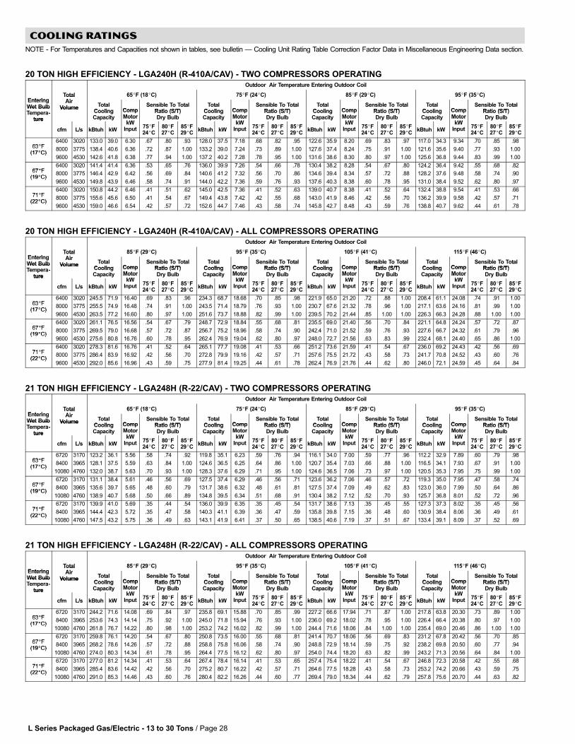
L Series Packaged Gas/Electric − 13 to 30 Tons / Page 28
COOLING RATINGS
NOTE − For Temperatures and Capacities not shown in tables, see bulletin � Cooling Unit Rating Table Correction Factor Data in Miscellaneous Engineering Data section.
20 TON HIGH EFFICIENCY − LGA240H (R−410A/CAV) − TWO COMPRESSORS OPERATINGOutdoor Air Temperature Entering Outdoor Coil
EnteringTotalAi
65�F (18�C) 75�F (24�C) 85�F (29�C) 95�F (35�C)EnteringWet Bulb
TotalAir
Volume TotalCooling Comp
Sensible To TotalRatio (S/T)
TotalCooling Comp
Sensible To TotalRatio (S/T)
TotalCooling Comp
Sensible To TotalRatio (S/T)
TotalCooling Comp
Sensible To TotalRatio (S/T)
Wet BulbTempera-
ture
VolumeCoolingCapacity
CompMotor
kW
Ratio (S/T)Dry Bulb
CoolingCapacity
CompMotor
kW
Ratio (S/T)Dry Bulb
CoolingCapacity
CompMotor
kW
Ratio (S/T)Dry Bulb
CoolingCapacity
CompMotor
kW
Ratio (S/T)Dry Bulbture
cfm L/s kBtuh kW
MotorkW
Input 75�F24�C
80�F27�C
85�F29�C
kBtuh kW
MotorkW
Input 75�F24�C
80�F27�C
85�F29�C
kBtuh kW
MotorkW
Input 75�F24�C
80�F27�C
85�F29�C
kBtuh kW
MotorkW
Input 75�F24�C
80�F27�C
85�F29�C
63�F6400 3020 133.0 39.0 6.30 .67 .80 .93 128.0 37.5 7.18 .68 .82 .95 122.6 35.9 8.20 .69 .83 .97 117.0 34.3 9.34 .70 .85 .98
63�F(17�C)
8000 3775 138.4 40.6 6.36 .72 .87 1.00 133.2 39.0 7.24 .73 .89 1.00 127.6 37.4 8.24 .75 .91 1.00 121.6 35.6 9.40 .77 .93 1.00(17�C)
9600 4530 142.6 41.8 6.38 .77 .94 1.00 137.2 40.2 7.28 .78 .95 1.00 131.6 38.6 8.30 .80 .97 1.00 125.6 36.8 9.44 .83 .99 1.00
67�F6400 3020 141.4 41.4 6.36 .53 .65 .76 136.0 39.9 7.26 .54 .66 .78 130.4 38.2 8.28 .54 .67 .80 124.2 36.4 9.42 .55 .68 .82
67�F(19�C)
8000 3775 146.4 42.9 6.42 .56 .69 .84 140.6 41.2 7.32 .56 .70 .86 134.6 39.4 8.34 .57 .72 .88 128.2 37.6 9.48 .58 .74 .90(19�C)
9600 4530 149.8 43.9 6.46 .58 .74 .91 144.0 42.2 7.36 .59 .76 .93 137.6 40.3 8.38 .60 .78 .95 131.0 38.4 9.52 .62 .80 .97
71�F6400 3020 150.8 44.2 6.46 .41 .51 .62 145.0 42.5 7.36 .41 .52 .63 139.0 40.7 8.38 .41 .52 .64 132.4 38.8 9.54 .41 .53 .66
71�F(22�C)
8000 3775 155.6 45.6 6.50 .41 .54 .67 149.4 43.8 7.42 .42 .55 .68 143.0 41.9 8.46 .42 .56 .70 136.2 39.9 9.58 .42 .57 .71(22�C)
9600 4530 159.0 46.6 6.54 .42 .57 .72 152.6 44.7 7.46 .43 .58 .74 145.8 42.7 8.48 .43 .59 .76 138.8 40.7 9.62 .44 .61 .78
20 TON HIGH EFFICIENCY − LGA240H (R−410A/CAV) − ALL COMPRESSORS OPERATINGOutdoor Air Temperature Entering Outdoor Coil
EnteringTotalAi
85�F (29�C) 95�F (35�C) 105�F (41�C) 115�F (46�C)EnteringWet Bulb
TotalAir
Volume TotalCooling Comp
Sensible To TotalRatio (S/T)
TotalCooling Comp
Sensible To TotalRatio (S/T)
TotalCooling Comp
Sensible To TotalRatio (S/T)
TotalCooling Comp
Sensible To TotalRatio (S/T)
Wet BulbTempera-
ture
VolumeCoolingCapacity
CompMotor
kW
Ratio (S/T)Dry Bulb
CoolingCapacity
CompMotor
kW
Ratio (S/T)Dry Bulb
CoolingCapacity
CompMotor
kW
Ratio (S/T)Dry Bulb
CoolingCapacity
CompMotor
kW
Ratio (S/T)Dry Bulbture
cfm L/s kBtuh kW
MotorkW
Input 75�F24�C
80�F27�C
85�F29�C
kBtuh kW
MotorkW
Input 75�F24�C
80�F27�C
85�F29�C
kBtuh kW
MotorkW
Input 75�F24�C
80�F27�C
85�F29�C
kBtuh kW
MotorkW
Input 75�F24�C
80�F27�C
85�F29�C
63�F6400 3020 245.5 71.9 16.40 .69 .83 .96 234.3 68.7 18.68 .70 .85 .98 221.9 65.0 21.20 .72 .88 1.00 208.4 61.1 24.08 .74 .91 1.00
63�F(17�C)
8000 3775 255.5 74.9 16.48 .74 .91 1.00 243.5 71.4 18.79 .76 .93 1.00 230.7 67.6 21.32 .78 .96 1.00 217.1 63.6 24.16 .81 .99 1.00(17�C)
9600 4530 263.5 77.2 16.60 .80 .97 1.00 251.6 73.7 18.88 .82 .99 1.00 239.5 70.2 21.44 .85 1.00 1.00 226.3 66.3 24.28 .88 1.00 1.00
67�F6400 3020 261.1 76.5 16.56 .54 .67 .79 248.7 72.9 18.84 .55 .68 .81 235.5 69.0 21.40 .56 .70 .84 221.1 64.8 24.24 .57 .72 .87
67�F(19�C)
8000 3775 269.5 79.0 16.68 .57 .72 .87 256.7 75.2 18.96 .58 .74 .90 242.4 71.0 21.52 .59 .76 .93 227.6 66.7 24.32 .61 .79 .96(19�C)
9600 4530 275.6 80.8 16.76 .60 .78 .95 262.4 76.9 19.04 .62 .80 .97 248.0 72.7 21.56 .63 .83 .99 232.4 68.1 24.40 .65 .86 1.00
71�F6400 3020 278.3 81.6 16.76 .41 .52 .64 265.1 77.7 19.08 .41 .53 .66 251.2 73.6 21.59 .41 .54 .67 236.0 69.2 24.43 .42 .56 .69
71�F(22�C)
8000 3775 286.4 83.9 16.92 .42 .56 .70 272.8 79.9 19.16 .42 .57 .71 257.6 75.5 21.72 .43 .58 .73 241.7 70.8 24.52 .43 .60 .76(22�C)
9600 4530 292.0 85.6 16.96 .43 .59 .75 277.9 81.4 19.25 .44 .61 .78 262.4 76.9 21.76 .44 .62 .80 246.0 72.1 24.59 .45 .64 .84
21 TON HIGH EFFICIENCY − LGA248H (R−22/CAV) − TWO COMPRESSORS OPERATINGOutdoor Air Temperature Entering Outdoor Coil
EnteringTotalAi
65�F (18�C) 75�F (24�C) 85�F (29�C) 95�F (35�C)EnteringWet Bulb
TotalAir
Volume TotalCooling Comp
Sensible To TotalRatio (S/T)
TotalCooling Comp
Sensible To TotalRatio (S/T)
TotalCooling Comp
Sensible To TotalRatio (S/T)
TotalCooling Comp
Sensible To TotalRatio (S/T)
Wet BulbTempera-
ture
VolumeCoolingCapacity
CompMotor
kW
Ratio (S/T)Dry Bulb
CoolingCapacity
CompMotor
kW
Ratio (S/T)Dry Bulb
CoolingCapacity
CompMotor
kW
Ratio (S/T)Dry Bulb
CoolingCapacity
CompMotor
kW
Ratio (S/T)Dry Bulbture
cfm L/s kBtuh kW
MotorkW
Input 75�F24�C
80�F27�C
85�F29�C
kBtuh kW
MotorkW
Input 75�F24�C
80�F27�C
85�F29�C
kBtuh kW
MotorkW
Input 75�F24�C
80�F27�C
85�F29�C
kBtuh kW
MotorkW
Input 75�F24�C
80�F27�C
85�F29�C
63�F6720 3170 123.2 36.1 5.56 .58 .74 .92 119.8 35.1 6.23 .59 .76 .94 116.1 34.0 7.00 .59 .77 .96 112.2 32.9 7.89 .60 .79 .98
63�F(17�C)
8400 3965 128.1 37.5 5.59 .63 .84 1.00 124.6 36.5 6.25 .64 .86 1.00 120.7 35.4 7.03 .66 .88 1.00 116.5 34.1 7.93 .67 .91 1.00(17�C)
10080 4760 132.0 38.7 5.63 .70 .93 1.00 128.3 37.6 6.29 .71 .95 1.00 124.6 36.5 7.06 .73 .97 1.00 120.5 35.3 7.95 .75 .99 1.00
67�F6720 3170 131.1 38.4 5.61 .46 .56 .69 127.5 37.4 6.29 .46 .56 .71 123.6 36.2 7.06 .46 .57 .72 119.3 35.0 7.95 .47 .58 .74
67�F(19�C)
8400 3965 135.6 39.7 5.65 .48 .60 .79 131.7 38.6 6.32 .48 .61 .81 127.5 37.4 7.09 .49 .62 .83 123.0 36.0 7.99 .50 .64 .86(19�C)
10080 4760 138.9 40.7 5.68 .50 .66 .89 134.8 39.5 6.34 .51 .68 .91 130.4 38.2 7.12 .52 .70 .93 125.7 36.8 8.01 .52 .72 .96
71�F6720 3170 139.9 41.0 5.69 .35 .44 .54 136.0 39.9 6.35 .35 .45 .54 131.7 38.6 7.13 .35 .45 .55 127.3 37.3 8.02 .35 .45 .56
71�F(22�C)
8400 3965 144.4 42.3 5.72 .35 .47 .58 140.3 41.1 6.39 .36 .47 .59 135.8 39.8 7.15 .36 .48 .60 130.9 38.4 8.06 .36 .49 .61(22�C)
10080 4760 147.5 43.2 5.75 .36 .49 .63 143.1 41.9 6.41 .37 .50 .65 138.5 40.6 7.19 .37 .51 .67 133.4 39.1 8.09 .37 .52 .69
21 TON HIGH EFFICIENCY − LGA248H (R−22/CAV) − ALL COMPRESSORS OPERATINGOutdoor Air Temperature Entering Outdoor Coil
EnteringTotalAi
85�F (29�C) 95�F (35�C) 105�F (41�C) 115�F (46�C)EnteringWet Bulb
TotalAir
Volume TotalCooling Comp
Sensible To TotalRatio (S/T)
TotalCooling Comp
Sensible To TotalRatio (S/T)
TotalCooling Comp
Sensible To TotalRatio (S/T)
TotalCooling Comp
Sensible To TotalRatio (S/T)
Wet BulbTempera-
ture
VolumeCoolingCapacity
CompMotor
kW
Ratio (S/T)Dry Bulb
CoolingCapacity
CompMotor
kW
Ratio (S/T)Dry Bulb
CoolingCapacity
CompMotor
kW
Ratio (S/T)Dry Bulb
CoolingCapacity
CompMotor
kW
Ratio (S/T)Dry Bulbture
cfm L/s kBtuh kW
MotorkW
Input 75�F24�C
80�F27�C
85�F29�C
kBtuh kW
MotorkW
Input 75�F24�C
80�F27�C
85�F29�C
kBtuh kW
MotorkW
Input 75�F24�C
80�F27�C
85�F29�C
kBtuh kW
MotorkW
Input 75�F24�C
80�F27�C
85�F29�C
63�F6720 3170 244.2 71.6 14.08 .69 .84 .97 235.8 69.1 15.88 .70 .85 .99 227.2 66.6 17.94 .71 .87 1.00 217.8 63.8 20.30 .73 .89 1.00
63�F(17�C)
8400 3965 253.6 74.3 14.14 .75 .92 1.00 245.0 71.8 15.94 .76 .93 1.00 236.0 69.2 18.02 .78 .95 1.00 226.4 66.4 20.38 .80 .97 1.00(17�C)
10080 4760 261.8 76.7 14.22 .80 .98 1.00 253.2 74.2 16.02 .82 .99 1.00 244.4 71.6 18.06 .84 1.00 1.00 235.4 69.0 20.46 .86 1.00 1.00
67�F6720 3170 259.8 76.1 14.20 .54 .67 .80 250.8 73.5 16.00 .55 .68 .81 241.4 70.7 18.06 .56 .69 .83 231.2 67.8 20.42 .56 .70 .85
67�F(19�C)
8400 3965 268.2 78.6 14.26 .57 .72 .88 258.8 75.8 16.06 .58 .74 .90 248.8 72.9 18.14 .59 .75 .92 238.2 69.8 20.50 .60 .77 .94(19�C)
10080 4760 274.0 80.3 14.34 .61 .78 .95 264.4 77.5 16.12 .62 .80 .97 254.0 74.4 18.20 .63 .82 .99 243.2 71.3 20.56 .64 .84 1.00
71�F6720 3170 277.0 81.2 14.34 .41 .53 .64 267.4 78.4 16.14 .41 .53 .65 257.4 75.4 18.22 .41 .54 .67 246.8 72.3 20.58 .42 .55 .68
71�F(22�C)
8400 3965 285.4 83.6 14.42 .42 .56 .70 275.2 80.7 16.22 .42 .57 .71 264.6 77.5 18.28 .43 .58 .73 253.2 74.2 20.66 .43 .59 .75(22�C)
10080 4760 291.0 85.3 14.46 .43 .60 .76 280.4 82.2 16.26 .44 .60 .77 269.4 79.0 18.34 .44 .62 .79 257.8 75.6 20.70 .44 .63 .82
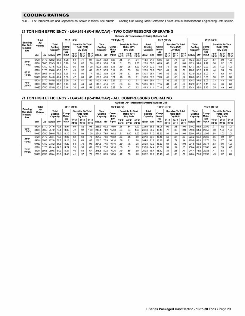
L Series Packaged Gas/Electric − 13 to 30 Tons / Page 29
COOLING RATINGS
NOTE − For Temperatures and Capacities not shown in tables, see bulletin � Cooling Unit Rating Table Correction Factor Data in Miscellaneous Engineering Data section.
21 TON HIGH EFFICIENCY − LGA248H (R−410A/CAV) − TWO COMPRESSORS OPERATINGOutdoor Air Temperature Entering Outdoor Coil
EnteringTotalAi
65�F (18�C) 75�F (24�C) 85�F (29�C) 95�F (35�C)EnteringWet Bulb
TotalAir
Volume TotalCooling Comp
Sensible To TotalRatio (S/T)
TotalCooling Comp
Sensible To TotalRatio (S/T)
TotalCooling Comp
Sensible To TotalRatio (S/T)
TotalCooling Comp
Sensible To TotalRatio (S/T)
Wet BulbTempera-
ture
VolumeCoolingCapacity
CompMotor
kW
Ratio (S/T)Dry Bulb
CoolingCapacity
CompMotor
kW
Ratio (S/T)Dry Bulb
CoolingCapacity
CompMotor
kW
Ratio (S/T)Dry Bulb
CoolingCapacity
CompMotor
kW
Ratio (S/T)Dry Bulbture
cfm L/s kBtuh kW
MotorkW
Input 75�F24�C
80�F27�C
85�F29�C
kBtuh kW
MotorkW
Input 75�F24�C
80�F27�C
85�F29�C
kBtuh kW
MotorkW
Input 75�F24�C
80�F27�C
85�F29�C
kBtuh kW
MotorkW
Input 75�F24�C
80�F27�C
85�F29�C
63�F6720 3170 128.2 37.6 5.25 .54 .71 .91 123.4 36.2 6.08 .55 .74 .94 118.3 34.7 6.95 .56 .76 .97 112.9 33.1 7.91 .57 .80 1.00
63�F(17�C)
8400 3965 133.5 39.1 5.29 .59 .82 1.00 128.4 37.6 6.11 .61 .85 1.00 123.0 36.0 6.99 .63 .88 1.00 117.4 34.4 7.97 .66 .92 1.00(17�C)
10080 4760 137.6 40.3 5.33 .66 .92 1.00 132.5 38.8 6.15 .69 .95 1.00 127.2 37.3 7.03 .71 .98 1.00 121.7 35.7 7.99 .75 1.00 1.00
67�F6720 3170 136.6 40.0 5.31 .43 .52 .66 131.5 38.5 6.14 .43 .53 .68 126.0 36.9 7.02 .44 .54 .71 120.2 35.2 7.99 .44 .55 .74
67�F(19�C)
8400 3965 141.5 41.5 5.35 .45 .56 .77 136.0 39.9 6.17 .46 .57 .80 130.1 38.1 7.06 .46 .59 .83 123.9 36.3 8.03 .47 .62 .87(19�C)
10080 4760 144.8 42.4 5.38 .47 .63 .87 139.1 40.8 6.21 .48 .65 .91 133.0 39.0 7.09 .49 .68 .94 126.6 37.1 8.05 .50 .72 .98
71�F6720 3170 145.9 42.8 5.39 .33 .41 .50 140.4 41.1 6.22 .33 .42 .51 134.6 39.4 7.11 .33 .42 .52 128.3 37.6 8.07 .33 .43 .53
71�F(22�C)
8400 3965 150.7 44.2 5.43 .33 .44 .54 144.8 42.4 6.26 .33 .44 .55 138.6 40.6 7.15 .34 .45 .57 132.0 38.7 8.11 .34 .46 .59(22�C)
10080 4760 153.9 45.1 5.46 .34 .46 .59 147.8 43.3 6.29 .34 .47 .62 141.3 41.4 7.18 .35 .48 .65 134.4 39.4 8.15 .35 .49 .68
21 TON HIGH EFFICIENCY − LGA248H (R−410A/CAV) − ALL COMPRESSORS OPERATINGOutdoor Air Temperature Entering Outdoor Coil
EnteringTotalAi
85�F (29�C) 95�F (35�C) 105�F (41�C) 115�F (46�C)EnteringWet Bulb
TotalAir
Volume TotalCooling Comp
Sensible To TotalRatio (S/T)
TotalCooling Comp
Sensible To TotalRatio (S/T)
TotalCooling Comp
Sensible To TotalRatio (S/T)
TotalCooling Comp
Sensible To TotalRatio (S/T)
Wet BulbTempera-
ture
VolumeCoolingCapacity
CompMotor
kW
Ratio (S/T)Dry Bulb
CoolingCapacity
CompMotor
kW
Ratio (S/T)Dry Bulb
CoolingCapacity
CompMotor
kW
Ratio (S/T)Dry Bulb
CoolingCapacity
CompMotor
kW
Ratio (S/T)Dry Bulbture
cfm L/s kBtuh kW
MotorkW
Input 75�F24�C
80�F27�C
85�F29�C
kBtuh kW
MotorkW
Input 75�F24�C
80�F27�C
85�F29�C
kBtuh kW
MotorkW
Input 75�F24�C
80�F27�C
85�F29�C
kBtuh kW
MotorkW
Input 75�F24�C
80�F27�C
85�F29�C
63�F6720 3170 247.6 72.6 13.94 .66 .82 .98 236.2 69.2 15.86 .68 .84 1.00 223.6 65.5 18.06 .69 .88 1.00 210.2 61.6 20.50 .71 .92 1.00
63�F(17�C)
8400 3965 257.2 75.4 14.02 .72 .92 1.00 245.4 71.9 15.98 .74 .94 1.00 232.8 68.2 18.14 .77 .97 1.00 219.8 64.4 20.58 .80 1.00 1.00(17�C)
10080 4760 266.0 78.0 14.10 .78 .99 1.00 254.4 74.6 16.02 .81 1.00 1.00 242.4 71.0 18.22 .84 1.00 1.00 229.4 67.2 20.66 .88 1.00 1.00
67�F6720 3170 263.4 77.2 14.08 .52 .64 .78 251.2 73.6 16.02 .53 .65 .80 237.8 69.7 18.18 .53 .67 .83 223.2 65.4 20.62 .55 .69 .87
67�F(19�C)
8400 3965 272.0 79.7 14.16 .55 .69 .87 259.0 75.9 16.10 .56 .71 .90 244.8 71.7 18.26 .57 .74 .94 229.8 67.3 20.70 .59 .77 .98(19�C)
10080 4760 278.2 81.5 14.22 .58 .76 .96 264.6 77.5 16.16 .59 .78 .98 250.0 73.3 18.30 .61 .82 1.00 234.6 68.8 20.74 .63 .86 1.00
71�F6720 3170 281.4 82.5 14.24 .39 .50 .62 268.2 78.6 16.18 .39 .51 .63 253.8 74.4 18.36 .39 .52 .65 238.4 69.9 20.80 .40 .53 .67
71�F(22�C)
8400 3965 289.8 84.9 14.34 .40 .54 .67 275.6 80.8 16.26 .40 .55 .69 260.8 76.4 18.42 .41 .56 .71 244.4 71.6 20.86 .41 .58 .74(22�C)
10080 4760 295.4 86.6 14.40 .41 .57 .73 280.8 82.3 16.34 .42 .58 .76 265.2 77.7 18.48 .42 .60 .79 248.4 72.8 20.90 .43 .62 .83
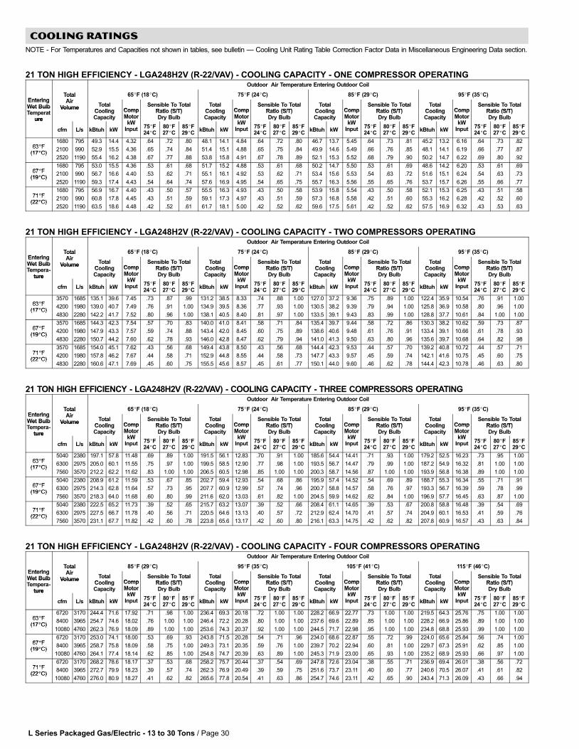
L Series Packaged Gas/Electric − 13 to 30 Tons / Page 30
COOLING RATINGS
NOTE − For Temperatures and Capacities not shown in tables, see bulletin � Cooling Unit Rating Table Correction Factor Data in Miscellaneous Engineering Data section.
21 TON HIGH EFFICIENCY − LGA248H2V (R−22/VAV) − COOLING CAPACITY − ONE COMPRESSOR OPERATINGOutdoor Air Temperature Entering Outdoor Coil
EnteringTotalAi
65�F (18�C) 75�F (24�C) 85�F (29�C) 95�F (35�C)EnteringWet Bulb
TotalAir
Volume TotalCooling Comp
Sensible To TotalRatio (S/T)
TotalCooling Comp
Sensible To TotalRatio (S/T)
TotalCooling Comp
Sensible To TotalRatio (S/T)
TotalCooling Comp
Sensible To TotalRatio (S/T)
Wet BulbTemperat
ure
VolumeCoolingCapacity
CompMotor
kW
Ratio (S/T)Dry Bulb
CoolingCapacity
CompMotor
kW
Ratio (S/T)Dry Bulb
CoolingCapacity
CompMotor
kW
Ratio (S/T)Dry Bulb
CoolingCapacity
CompMotor
kW
Ratio (S/T)Dry Bulbure
cfm L/s kBtuh kW
MotorkW
Input 75�F24�C
80�F27�C
85�F29�C
kBtuh kW
MotorkW
Input 75�F24�C
80�F27�C
85�F29�C
kBtuh kW
MotorkW
Input 75�F24�C
80�F27�C
85�F29�C
kBtuh kW
MotorkW
Input 75�F24�C
80�F27�C
85�F29�C
63�F1680 795 49.3 14.4 4.32 .64 .72 .80 48.1 14.1 4.84 .64 .72 .80 46.7 13.7 5.45 .64 .73 .81 45.2 13.2 6.16 .64 .73 .82
63�F(17�C)
2100 990 52.9 15.5 4.36 .65 .74 .84 51.4 15.1 4.88 .65 .75 .84 49.9 14.6 5.49 .66 .76 .85 48.1 14.1 6.19 .66 .77 .87(17�C)
2520 1190 55.4 16.2 4.38 .67 .77 .88 53.8 15.8 4.91 .67 .78 .89 52.1 15.3 5.52 .68 .79 .90 50.2 14.7 6.22 .69 .80 .92
67�F1680 795 53.0 15.5 4.36 .53 .61 .68 51.7 15.2 4.88 .53 .61 .68 50.2 14.7 5.50 .53 .61 .69 48.6 14.2 6.20 .53 .61 .69
67�F(19�C)
2100 990 56.7 16.6 4.40 .53 .62 .71 55.1 16.1 4.92 .53 .62 .71 53.4 15.6 5.53 .54 .63 .72 51.6 15.1 6.24 .54 .63 .73(19�C)
2520 1190 59.3 17.4 4.43 .54 .64 .74 57.6 16.9 4.95 .54 .65 .75 55.7 16.3 5.56 .55 .65 .76 53.7 15.7 6.26 .55 .66 .77
71�F1680 795 56.9 16.7 4.40 .43 .50 .57 55.5 16.3 4.93 .43 .50 .58 53.9 15.8 5.54 .43 .50 .58 52.1 15.3 6.25 .43 .51 .58
71�F(22�C)
2100 990 60.8 17.8 4.45 .43 .51 .59 59.1 17.3 4.97 .43 .51 .59 57.3 16.8 5.58 .42 .51 .60 55.3 16.2 6.28 .42 .52 .60(22�C)
2520 1190 63.5 18.6 4.48 .42 .52 .61 61.7 18.1 5.00 .42 .52 .62 59.6 17.5 5.61 .42 .52 .62 57.5 16.9 6.32 .43 .53 .63
21 TON HIGH EFFICIENCY − LGA248H2V (R−22/VAV) − COOLING CAPACITY − TWO COMPRESSORS OPERATINGOutdoor Air Temperature Entering Outdoor Coil
EnteringTotalAi
65�F (18�C) 75�F (24�C) 85�F (29�C) 95�F (35�C)EnteringWet Bulb
TotalAir
Volume TotalCooling Comp
Sensible To TotalRatio (S/T)
TotalCooling Comp
Sensible To TotalRatio (S/T)
TotalCooling Comp
Sensible To TotalRatio (S/T)
TotalCooling Comp
Sensible To TotalRatio (S/T)
Wet BulbTempera-
ture
VolumeCoolingCapacity
CompMotor
kW
Ratio (S/T)Dry Bulb
CoolingCapacity
CompMotor
kW
Ratio (S/T)Dry Bulb
CoolingCapacity
CompMotor
kW
Ratio (S/T)Dry Bulb
CoolingCapacity
CompMotor
kW
Ratio (S/T)Dry Bulbture
cfm L/s kBtuh kW
MotorkW
Input 75�F24�C
80�F27�C
85�F29�C
kBtuh kW
MotorkW
Input 75�F24�C
80�F27�C
85�F29�C
kBtuh kW
MotorkW
Input 75�F24�C
80�F27�C
85�F29�C
kBtuh kW
MotorkW
Input 75�F24�C
80�F27�C
85�F29�C
63�F3570 1685 135.1 39.6 7.45 .73 .87 .99 131.2 38.5 8.33 .74 .88 1.00 127.0 37.2 9.36 .75 .89 1.00 122.4 35.9 10.54 .76 .91 1.00
63�F(17�C)
4200 1980 139.0 40.7 7.49 .76 .91 1.00 134.9 39.5 8.36 .77 .93 1.00 130.5 38.2 9.39 .79 .94 1.00 125.8 36.9 10.58 .80 .96 1.00(17�C)
4830 2280 142.2 41.7 7.52 .80 .96 1.00 138.1 40.5 8.40 .81 .97 1.00 133.5 39.1 9.43 .83 .99 1.00 128.8 37.7 10.61 .84 1.00 1.00
67�F3570 1685 144.3 42.3 7.54 .57 .70 .83 140.0 41.0 8.41 .58 .71 .84 135.4 39.7 9.44 .58 .72 .86 130.3 38.2 10.62 .59 .73 .87
67�F(19�C)
4200 1980 147.9 43.3 7.57 .59 .74 .88 143.4 42.0 8.45 .60 .75 .89 138.6 40.6 9.48 .61 .76 .91 133.4 39.1 10.66 .61 .78 .93(19�C)
4830 2280 150.7 44.2 7.60 .62 .78 .93 146.0 42.8 8.47 .62 .79 .94 141.0 41.3 9.50 .63 .80 .96 135.6 39.7 10.68 .64 .82 .98
71�F3570 1685 154.0 45.1 7.62 .43 .56 .68 149.4 43.8 8.50 .43 .56 .68 144.4 42.3 9.53 .44 .57 .70 139.2 40.8 10.72 .44 .57 .71
71�F(22�C)
4200 1980 157.8 46.2 7.67 .44 .58 .71 152.9 44.8 8.55 .44 .58 .73 147.7 43.3 9.57 .45 .59 .74 142.1 41.6 10.75 .45 .60 .75(22�C)
4830 2280 160.6 47.1 7.69 .45 .60 .75 155.5 45.6 8.57 .45 .61 .77 150.1 44.0 9.60 .46 .62 .78 144.4 42.3 10.78 .46 .63 .80
21 TON HIGH EFFICIENCY − LGA248H2V (R−22/VAV) − COOLING CAPACITY − THREE COMPRESSORS OPERATINGOutdoor Air Temperature Entering Outdoor Coil
EnteringTotalAi
65�F (18�C) 75�F (24�C) 85�F (29�C) 95�F (35�C)EnteringWet Bulb
TotalAir
Volume TotalCooling Comp
Sensible To TotalRatio (S/T)
TotalCooling Comp
Sensible To TotalRatio (S/T)
TotalCooling Comp
Sensible To TotalRatio (S/T)
TotalCooling Comp
Sensible To TotalRatio (S/T)
Wet BulbTempera-
ture
VolumeCoolingCapacity
CompMotor
kW
Ratio (S/T)Dry Bulb
CoolingCapacity
CompMotor
kW
Ratio (S/T)Dry Bulb
CoolingCapacity
CompMotor
kW
Ratio (S/T)Dry Bulb
CoolingCapacity
CompMotor
kW
Ratio (S/T)Dry Bulbture
cfm L/s kBtuh kW
MotorkW
Input 75�F24�C
80�F27�C
85�F29�C
kBtuh kW
MotorkW
Input 75�F24�C
80�F27�C
85�F29�C
kBtuh kW
MotorkW
Input 75�F24�C
80�F27�C
85�F29�C
kBtuh kW
MotorkW
Input 75�F24�C
80�F27�C
85�F29�C
63�F5040 2380 197.1 57.8 11.48 .69 .89 1.00 191.5 56.1 12.83 .70 .91 1.00 185.6 54.4 14.41 .71 .93 1.00 179.2 52.5 16.23 .73 .95 1.00
63�F(17�C)
6300 2975 205.0 60.1 11.55 .75 .97 1.00 199.5 58.5 12.90 .77 .98 1.00 193.5 56.7 14.47 .79 .99 1.00 187.2 54.9 16.32 .81 1.00 1.00(17�C)
7560 3570 212.2 62.2 11.62 .83 1.00 1.00 206.5 60.5 12.98 .85 1.00 1.00 200.3 58.7 14.56 .87 1.00 1.00 193.9 56.8 16.38 .89 1.00 1.00
67�F5040 2380 208.9 61.2 11.59 .53 .67 .85 202.7 59.4 12.93 .54 .68 .86 195.9 57.4 14.52 .54 .69 .89 188.7 55.3 16.34 .55 .71 .91
67�F(19�C)
6300 2975 214.3 62.8 11.64 .57 .73 .95 207.7 60.9 12.99 .57 .74 .96 200.7 58.8 14.57 .58 .76 .97 193.3 56.7 16.39 .59 .78 .99(19�C)
7560 3570 218.3 64.0 11.68 .60 .80 .99 211.6 62.0 13.03 .61 .82 1.00 204.5 59.9 14.62 .62 .84 1.00 196.9 57.7 16.45 .63 .87 1.00
71�F5040 2380 222.5 65.2 11.73 .39 .52 .65 215.7 63.2 13.07 .39 .52 .66 208.4 61.1 14.65 .39 .53 .67 200.8 58.8 16.48 .39 .54 .69
71�F(22�C)
6300 2975 227.5 66.7 11.78 .40 .56 .71 220.5 64.6 13.13 .40 .57 .72 212.9 62.4 14.70 .41 .57 .74 204.9 60.1 16.53 .41 .59 .76(22�C)
7560 3570 231.1 67.7 11.82 .42 .60 .78 223.8 65.6 13.17 .42 .60 .80 216.1 63.3 14.75 .42 .62 .82 207.8 60.9 16.57 .43 .63 .84
21 TON HIGH EFFICIENCY − LGA248H2V (R−22/VAV) − COOLING CAPACITY − FOUR COMPRESSORS OPERATINGOutdoor Air Temperature Entering Outdoor Coil
EnteringTotalAi
85�F (29�C) 95�F (35�C) 105�F (41�C) 115�F (46�C)EnteringWet Bulb
TotalAir
Volume TotalCooling Comp
Sensible To TotalRatio (S/T)
TotalCooling Comp
Sensible To TotalRatio (S/T)
TotalCooling Comp
Sensible To TotalRatio (S/T)
TotalCooling Comp
Sensible To TotalRatio (S/T)
Wet BulbTempera-
ture
VolumeCoolingCapacity
CompMotor
kW
Ratio (S/T)Dry Bulb
CoolingCapacity
CompMotor
kW
Ratio (S/T)Dry Bulb
CoolingCapacity
CompMotor
kW
Ratio (S/T)Dry Bulb
CoolingCapacity
CompMotor
kW
Ratio (S/T)Dry Bulbture
cfm L/s kBtuh kW
MotorkW
Input 75�F24�C
80�F27�C
85�F29�C
kBtuh kW
MotorkW
Input 75�F24�C
80�F27�C
85�F29�C
kBtuh kW
MotorkW
Input 75�F24�C
80�F27�C
85�F29�C
kBtuh kW
MotorkW
Input 75�F24�C
80�F27�C
85�F29�C
63�F6720 3170 244.4 71.6 17.92 .71 .98 1.00 236.4 69.3 20.18 .72 1.00 1.00 228.2 66.9 22.77 .73 1.00 1.00 219.5 64.3 25.76 .75 1.00 1.00
63�F(17�C)
8400 3965 254.7 74.6 18.02 .76 1.00 1.00 246.4 72.2 20.28 .80 1.00 1.00 237.6 69.6 22.89 .85 1.00 1.00 228.2 66.9 25.86 .89 1.00 1.00(17�C)
10080 4760 262.3 76.9 18.09 .89 1.00 1.00 253.6 74.3 20.37 .92 1.00 1.00 244.5 71.7 22.98 .95 1.00 1.00 234.8 68.8 25.93 .99 1.00 1.00
67�F6720 3170 253.0 74.1 18.00 .53 .69 .93 243.8 71.5 20.28 .54 .71 .96 234.0 68.6 22.87 .55 .72 .99 224.0 65.6 25.84 .56 .74 1.00
67�F(19�C)
8400 3965 258.7 75.8 18.09 .58 .75 1.00 249.3 73.1 20.35 .59 .76 1.00 239.7 70.2 22.94 .60 .81 1.00 229.7 67.3 25.91 .62 .85 1.00(19�C)
10080 4760 264.1 77.4 18.14 .62 .85 1.00 254.8 74.7 20.39 .63 .89 1.00 245.3 71.9 23.00 .65 .93 1.00 235.2 68.9 25.93 .66 .97 1.00
71�F6720 3170 268.2 78.6 18.17 .37 .53 .68 258.2 75.7 20.44 .37 .54 .69 247.8 72.6 23.04 .38 .55 .71 236.9 69.4 26.01 .38 .56 .72
71�F(22�C)
8400 3965 272.7 79.9 18.23 .39 .57 .74 262.3 76.9 20.49 .39 .59 .75 251.6 73.7 23.11 .40 .60 .77 240.6 70.5 26.07 .41 .61 .82(22�C)
10080 4760 276.0 80.9 18.27 .41 .62 .82 265.6 77.8 20.54 .41 .63 .86 254.7 74.6 23.11 .42 .65 .90 243.4 71.3 26.09 .43 .66 .94

L Series Packaged Gas/Electric − 13 to 30 Tons / Page 31
COOLING RATINGS
NOTE − For Temperatures and Capacities not shown in tables, see bulletin � Cooling Unit Rating Table Correction Factor Data in Miscellaneous Engineering Data section.
25 TON STANDARD EFFICIENCY − LGC300S (R−22/CAV) − TWO COMPRESSORS OPERATINGOutdoor Air Temperature Entering Outdoor Coil
EnteringTotalAi
65�F (18�C) 75�F (24�C) 85�F (29�C) 95�F (35�C)EnteringWet Bulb
TotalAir
Volume TotalCooling Comp
Sensible To TotalRatio (S/T)
TotalCooling Comp
Sensible To TotalRatio (S/T)
TotalCooling Comp
Sensible To TotalRatio (S/T)
TotalCooling Comp
Sensible To TotalRatio (S/T)
Wet BulbTempera-
ture
VolumeCoolingCapacity
CompMotor
kW
Ratio (S/T)Dry Bulb
CoolingCapacity
CompMotor
kW
Ratio (S/T)Dry Bulb
CoolingCapacity
CompMotor
kW
Ratio (S/T)Dry Bulb
CoolingCapacity
CompMotor
kW
Ratio (S/T)Dry Bulbture
cfm L/s kBtuh kW
MotorkW
Input 75�F24�C
80�F27�C
85�F29�C
kBtuh kW
MotorkW
Input 75�F24�C
80�F27�C
85�F29�C
kBtuh kW
MotorkW
Input 75�F24�C
80�F27�C
85�F29�C
kBtuh kW
MotorkW
Input 75�F24�C
80�F27�C
85�F29�C
63�F8000 3775 149.0 43.7 8.34 .61 .77 .94 144.6 42.4 9.28 .61 .78 .95 140.0 41.0 10.38 .62 .80 .97 135.0 39.6 11.62 .63 .82 .99
63�F(17�C)
10000 4720 154.6 45.3 8.46 .66 .86 1.00 150.0 44.0 9.42 .67 .88 1.00 145.2 42.6 10.50 .69 .90 1.00 140.0 41.0 11.74 .71 .93 1.00(17�C)
12000 5665 159.2 46.7 8.56 .73 .95 1.00 154.4 45.3 9.52 .74 .96 1.00 149.6 43.8 10.62 .76 .98 1.00 144.6 42.4 11.88 .78 1.00 1.00
67�F8000 3775 158.0 46.3 8.52 .48 .59 .72 153.2 44.9 9.48 .48 .59 .74 148.0 43.4 10.58 .49 .60 .75 142.8 41.9 11.82 .49 .61 .78
67�F(19�C)
10000 4720 162.8 47.7 8.64 .50 .63 .82 157.8 46.2 9.60 .51 .64 .84 152.4 44.7 10.70 .51 .66 .86 146.8 43.0 11.94 .52 .68 .89(19�C)
12000 5665 166.2 48.7 8.74 .53 .70 .91 161.0 47.2 9.70 .54 .71 .93 155.6 45.6 10.78 .55 .73 .95 149.8 43.9 12.04 .55 .76 .97
71�F8000 3775 167.8 49.2 8.76 .36 .46 .56 162.6 47.7 9.74 .36 .47 .57 157.4 46.1 10.82 .36 .47 .58 151.6 44.4 12.08 .37 .48 .59
71�F(22�C)
10000 4720 172.4 50.5 8.88 .37 .49 .61 167.2 49.0 9.84 .37 .50 .62 161.4 47.3 10.94 .37 .50 .63 155.4 45.5 12.20 .38 .51 .65(22�C)
12000 5665 175.6 51.5 8.96 .38 .52 .67 170.0 49.8 9.94 .38 .53 .69 164.2 48.1 11.02 .39 .54 .71 158.2 46.4 12.28 .39 .55 .73
25 TON STANDARD EFFICIENCY − LGC300S (R−22/CAV) − ALL COMPRESSORS OPERATINGOutdoor Air Temperature Entering Outdoor Coil
EnteringTotalAi
85�F (29�C) 95�F (35�C) 105�F (41�C) 115�F (46�C)EnteringWet Bulb
TotalAir
Volume TotalCooling Comp
Sensible To TotalRatio (S/T)
TotalCooling Comp
Sensible To TotalRatio (S/T)
TotalCooling Comp
Sensible To TotalRatio (S/T)
TotalCooling Comp
Sensible To TotalRatio (S/T)
Wet BulbTempera-
ture
VolumeCoolingCapacity
CompMotor
kW
Ratio (S/T)Dry Bulb
CoolingCapacity
CompMotor
kW
Ratio (S/T)Dry Bulb
CoolingCapacity
CompMotor
kW
Ratio (S/T)Dry Bulb
CoolingCapacity
CompMotor
kW
Ratio (S/T)Dry Bulbture
cfm L/s kBtuh kW
MotorkW
Input 75�F24�C
80�F27�C
85�F29�C
kBtuh kW
MotorkW
Input 75�F24�C
80�F27�C
85�F29�C
kBtuh kW
MotorkW
Input 75�F24�C
80�F27�C
85�F29�C
kBtuh kW
MotorkW
Input 75�F24�C
80�F27�C
85�F29�C
63�F8000 3775 291.5 85.4 20.90 .70 .86 1.00 281.1 82.4 23.41 .71 .88 1.00 270.1 79.2 26.23 .72 .90 1.00 258.4 75.7 29.44 .74 .92 1.00
63�F(17�C)
10000 4720 302.4 88.6 21.15 .76 .95 1.00 291.7 85.5 23.65 .77 .97 1.00 280.5 82.2 26.51 .79 .99 1.00 268.5 78.7 29.74 .81 1.00 1.00(17�C)
12000 5665 311.6 91.3 21.38 .82 1.00 1.00 301.3 88.3 23.92 .84 1.00 1.00 290.1 85.0 26.79 .86 1.00 1.00 278.7 81.7 30.05 .89 1.00 1.00
67�F8000 3775 308.4 90.4 21.30 .55 .68 .82 297.4 87.2 23.81 .55 .69 .84 285.5 83.7 26.67 .56 .70 .86 272.7 79.9 29.89 .57 .71 .88
67�F(19�C)
10000 4720 317.4 93.0 21.55 .58 .73 .91 305.9 89.7 24.05 .59 .75 .93 293.5 86.0 26.91 .60 .77 .96 280.2 82.1 30.17 .61 .79 .98(19�C)
12000 5665 324.1 95.0 21.71 .61 .80 .99 312.2 91.5 24.24 .62 .82 1.00 299.4 87.7 27.11 .63 .84 1.00 286.0 83.8 30.37 .65 .87 1.00
71�F8000 3775 327.8 96.1 21.79 .41 .53 .65 315.9 92.6 24.33 .41 .54 .66 303.4 88.9 27.23 .41 .55 .68 290.1 85.0 30.46 .42 .55 .69
71�F(22�C)
10000 4720 336.3 98.6 22.03 .42 .57 .71 323.9 94.9 24.57 .42 .58 .73 311.0 91.1 27.43 .43 .59 .74 297.0 87.0 30.67 .43 .60 .76(22�C)
12000 5665 342.1 100.3 22.20 .43 .60 .77 329.6 96.6 24.73 .44 .61 .79 316.0 92.6 27.63 .44 .63 .82 301.6 88.4 30.87 .45 .64 .84
25 TON HIGH EFFICIENCY − LGC300H (R−22/CAV) − TWO COMPRESSORS OPERATINGOutdoor Air Temperature Entering Outdoor Coil
EnteringTotalAi
65�F (18�C) 75�F (24�C) 85�F (29�C) 95�F (35�C)EnteringWet Bulb
TotalAir
Volume TotalCooling Comp
Sensible To TotalRatio (S/T)
TotalCooling Comp
Sensible To TotalRatio (S/T)
TotalCooling Comp
Sensible To TotalRatio (S/T)
TotalCooling Comp
Sensible To TotalRatio (S/T)
Wet BulbTempera-
ture
VolumeCoolingCapacity
CompMotor
kW
Ratio (S/T)Dry Bulb
CoolingCapacity
CompMotor
kW
Ratio (S/T)Dry Bulb
CoolingCapacity
CompMotor
kW
Ratio (S/T)Dry Bulb
CoolingCapacity
CompMotor
kW
Ratio (S/T)Dry Bulbture
cfm L/s kBtuh kW
MotorkW
Input 75�F24�C
80�F27�C
85�F29�C
kBtuh kW
MotorkW
Input 75�F24�C
80�F27�C
85�F29�C
kBtuh kW
MotorkW
Input 75�F24�C
80�F27�C
85�F29�C
kBtuh kW
MotorkW
Input 75�F24�C
80�F27�C
85�F29�C
63�F8000 3775 157.5 46.2 8.00 .58 .73 .90 152.7 44.8 9.01 .59 .75 .92 147.9 43.3 10.09 .60 .77 .94 143.0 41.9 11.28 .60 .79 .96
63�F(17�C)
10000 4720 163.6 47.9 8.08 .63 .83 .99 158.6 46.5 9.11 .64 .85 1.00 153.6 45.0 10.20 .65 .87 1.00 148.4 43.5 11.39 .67 .89 1.00(17�C)
12000 5665 168.5 49.4 8.14 .69 .91 1.00 163.4 47.9 9.17 .71 .93 1.00 158.4 46.4 10.28 .72 .95 1.00 153.1 44.9 11.49 .74 .97 1.00
67�F8000 3775 167.5 49.1 8.12 .46 .56 .69 162.4 47.6 9.16 .46 .57 .70 157.1 46.0 10.26 .47 .57 .72 151.8 44.5 11.46 .47 .58 .74
67�F(19�C)
10000 4720 173.2 50.8 8.19 .48 .60 .78 167.7 49.1 9.25 .49 .61 .80 162.2 47.5 10.36 .49 .62 .82 156.5 45.9 11.57 .50 .64 .85(19�C)
12000 5665 177.2 51.9 8.25 .51 .66 .87 171.5 50.3 9.31 .51 .67 .89 165.8 48.6 10.43 .52 .69 .91 160.0 46.9 11.64 .53 .71 .94
71�F8000 3775 178.5 52.3 8.27 .35 .44 .54 173.0 50.7 9.33 .35 .45 .55 167.5 49.1 10.45 .35 .45 .55 161.7 47.4 11.67 .35 .46 .56
71�F(22�C)
10000 4720 184.2 54.0 8.34 .36 .47 .58 178.3 52.3 9.41 .36 .47 .59 172.4 50.5 10.55 .36 .48 .60 166.3 48.7 11.77 .36 .49 .61(22�C)
12000 5665 187.9 55.1 8.39 .37 .49 .63 181.8 53.3 9.48 .37 .50 .65 175.7 51.5 10.61 .37 .51 .66 169.5 49.7 11.85 .37 .52 .69
25 TON HIGH EFFICIENCY − LGC300H (R−22/CAV) − ALL COMPRESSORS OPERATINGOutdoor Air Temperature Entering Outdoor Coil
EnteringTotalAi
85�F (29�C) 95�F (35�C) 105�F (41�C) 115�F (46�C)EnteringWet Bulb
TotalAir
Volume TotalCooling Comp
Sensible To TotalRatio (S/T)
TotalCooling Comp
Sensible To TotalRatio (S/T)
TotalCooling Comp
Sensible To TotalRatio (S/T)
TotalCooling Comp
Sensible To TotalRatio (S/T)
Wet BulbTempera-
ture
VolumeCoolingCapacity
CompMotor
kW
Ratio (S/T)Dry Bulb
CoolingCapacity
CompMotor
kW
Ratio (S/T)Dry Bulb
CoolingCapacity
CompMotor
kW
Ratio (S/T)Dry Bulb
CoolingCapacity
CompMotor
kW
Ratio (S/T)Dry Bulbture
cfm L/s kBtuh kW
MotorkW
Input 75�F24�C
80�F27�C
85�F29�C
kBtuh kW
MotorkW
Input 75�F24�C
80�F27�C
85�F29�C
kBtuh kW
MotorkW
Input 75�F24�C
80�F27�C
85�F29�C
kBtuh kW
MotorkW
Input 75�F24�C
80�F27�C
85�F29�C
63�F8000 3775 294.0 86.2 18.94 .67 .82 .96 284.2 83.3 21.18 .68 .83 .97 274.0 80.3 23.66 .69 .85 .99 262.6 77.0 26.46 .70 .87 1.00
63�F(17�C)
10000 4720 305.2 89.4 19.16 .72 .90 1.00 295.2 86.5 21.38 .74 .91 1.00 284.4 83.3 23.88 .75 .93 1.00 272.8 79.9 26.74 .77 .96 1.00(17�C)
12000 5665 314.8 92.3 19.30 .78 .96 1.00 304.2 89.2 21.56 .80 .98 1.00 293.6 86.0 24.06 .82 .99 1.00 282.2 82.7 26.98 .84 1.00 1.00
67�F8000 3775 312.4 91.6 19.26 .53 .65 .78 301.8 88.4 21.52 .53 .66 .79 290.6 85.2 24.06 .54 .67 .81 278.4 81.6 26.88 .55 .68 .83
67�F(19�C)
10000 4720 322.4 94.5 19.46 .56 .70 .86 311.2 91.2 21.70 .56 .71 .88 299.4 87.7 24.22 .57 .73 .90 286.6 84.0 27.08 .58 .75 .92(19�C)
12000 5665 329.6 96.6 19.58 .59 .76 .93 318.0 93.2 21.84 .59 .77 .95 305.6 89.6 24.40 .60 .79 .97 292.4 85.7 27.28 .62 .81 .99
71�F8000 3775 332.8 97.5 19.62 .40 .51 .62 321.4 94.2 21.90 .40 .52 .63 309.4 90.7 24.48 .40 .52 .65 296.4 86.9 27.34 .40 .53 .66
71�F(22�C)
10000 4720 342.6 100.4 19.80 .41 .54 .68 330.6 96.9 22.10 .41 .55 .69 318.0 93.2 24.66 .41 .56 .70 304.4 89.2 27.54 .42 .57 .72(22�C)
12000 5665 349.4 102.4 19.94 .42 .57 .73 337.0 98.8 22.24 .42 .58 .75 323.6 94.8 24.82 .43 .59 .77 309.8 90.8 27.70 .43 .61 .79
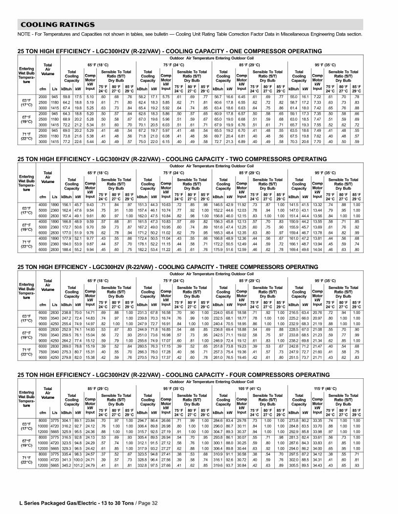
L Series Packaged Gas/Electric − 13 to 30 Tons / Page 32
COOLING RATINGS
NOTE − For Temperatures and Capacities not shown in tables, see bulletin � Cooling Unit Rating Table Correction Factor Data in Miscellaneous Engineering Data section.
25 TON HIGH EFFICIENCY − LGC300H2V (R−22/VAV) − COOLING CAPACITY − ONE COMPRESSOR OPERATINGOutdoor Air Temperature Entering Outdoor Coil
EnteringTotalAi
65�F (18�C) 75�F (24�C) 85�F (29�C) 95�F (35�C)EnteringWet Bulb
TotalAir
Volume TotalCooling Comp
Sensible To TotalRatio (S/T)
TotalCooling Comp
Sensible To TotalRatio (S/T)
TotalCooling Comp
Sensible To TotalRatio (S/T)
TotalCooling Comp
Sensible To TotalRatio (S/T)
Wet BulbTempera-
ture
VolumeCoolingCapacity
CompMotor
kW
Ratio (S/T)Dry Bulb
CoolingCapacity
CompMotor
kW
Ratio (S/T)Dry Bulb
CoolingCapacity
CompMotor
kW
Ratio (S/T)Dry Bulb
CoolingCapacity
CompMotor
kW
Ratio (S/T)Dry Bulbture
cfm L/s kBtuh kW
MotorkW
Input 75�F24�C
80�F27�C
85�F29�C
kBtuh kW
MotorkW
Input 75�F24�C
80�F27�C
85�F29�C
kBtuh kW
MotorkW
Input 75�F24�C
80�F27�C
85�F29�C
kBtuh kW
MotorkW
Input 75�F24�C
80�F27�C
85�F29�C
63�F2000 945 59.8 17.5 5.10 .60 .68 .76 58.2 17.1 5.75 .61 .69 .77 56.7 16.6 6.45 .61 .69 .77 55.0 16.1 7.22 .61 .70 .78
63�F(17�C)
2500 1180 64.2 18.8 5.19 .61 .71 .80 62.4 18.3 5.85 .62 .71 .81 60.6 17.8 6.55 .62 .72 .82 58.7 17.2 7.33 .63 .73 .83(17�C)
3000 1415 67.4 19.8 5.25 .63 .73 .84 65.4 19.2 5.92 .64 .74 .85 63.4 18.6 6.63 .64 .75 .86 61.4 18.0 7.42 .65 .76 .88
67�F2000 945 64.3 18.8 5.20 .50 .57 .64 62.6 18.3 5.86 .50 .57 .65 60.9 17.8 6.57 .50 .58 .65 59.1 17.3 7.35 .50 .58 .66
67�F(19�C)
2500 1180 68.9 20.2 5.28 .50 .58 .67 67.0 19.6 5.96 .51 .59 .67 65.0 19.0 6.68 .51 .59 .68 63.0 18.5 7.47 .51 .59 .69(19�C)
3000 1415 72.2 21.2 5.34 .51 .60 .70 70.1 20.5 6.03 .51 .61 .71 67.9 19.9 6.76 .51 .61 .71 65.7 19.3 7.55 .52 .62 .72
71�F2000 945 69.0 20.2 5.29 .41 .48 .54 67.2 19.7 5.97 .41 .48 .54 65.5 19.2 6.70 .41 .48 .55 63.5 18.6 7.49 .41 .48 .55
71�F(22�C)
2500 1180 73.8 21.6 5.38 .41 .48 .56 71.8 21.0 6.08 .41 .48 .56 69.7 20.4 6.81 .40 .48 .56 67.5 19.8 7.62 .40 .48 .57(22�C)
3000 1415 77.2 22.6 5.44 .40 .49 .57 75.0 22.0 6.15 .40 .49 .58 72.7 21.3 6.89 .40 .49 .58 70.3 20.6 7.70 .40 .50 .59
25 TON HIGH EFFICIENCY − LGC300H2V (R−22/VAV) − COOLING CAPACITY − TWO COMPRESSORS OPERATINGOutdoor Air Temperature Entering Outdoor Coil
EnteringTotalAi
65�F (18�C) 75�F (24�C) 85�F (29�C) 95�F (35�C)EnteringWet Bulb
TotalAir
Volume TotalCooling Comp
Sensible To TotalRatio (S/T)
TotalCooling Comp
Sensible To TotalRatio (S/T)
TotalCooling Comp
Sensible To TotalRatio (S/T)
TotalCooling Comp
Sensible To TotalRatio (S/T)
Wet BulbTempera-
ture
VolumeCoolingCapacity
CompMotor
kW
Ratio (S/T)Dry Bulb
CoolingCapacity
CompMotor
kW
Ratio (S/T)Dry Bulb
CoolingCapacity
CompMotor
kW
Ratio (S/T)Dry Bulb
CoolingCapacity
CompMotor
kW
Ratio (S/T)Dry Bulbture
cfm L/s kBtuh kW
MotorkW
Input 75�F24�C
80�F27�C
85�F29�C
kBtuh kW
MotorkW
Input 75�F24�C
80�F27�C
85�F29�C
kBtuh kW
MotorkW
Input 75�F24�C
80�F27�C
85�F29�C
kBtuh kW
MotorkW
Input 75�F24�C
80�F27�C
85�F29�C
63�F4000 1890 156.1 45.7 9.43 .71 .84 .97 151.3 44.3 10.63 .72 .85 .98 146.5 42.9 11.92 .73 .87 1.00 141.5 41.5 13.32 .74 .88 1.00
63�F(17�C)
5000 2360 162.4 47.6 9.54 .75 .91 1.00 157.4 46.1 10.74 .77 .92 1.00 152.2 44.6 12.03 .78 .94 1.00 147.0 43.1 13.44 .79 .95 1.00(17�C)
6000 2830 167.4 49.1 9.61 .80 .97 1.00 162.0 47.5 10.84 .82 .98 1.00 156.8 46.0 12.15 .83 1.00 1.00 151.4 44.4 13.56 .84 1.00 1.00
67�F4000 1890 166.8 48.9 9.59 .57 .68 .81 161.5 47.3 10.83 .57 .69 .82 156.3 45.8 12.13 .57 .70 .83 150.9 44.2 13.55 .58 .71 .85
67�F(19�C)
5000 2360 172.7 50.6 9.70 .59 .73 .87 167.2 49.0 10.95 .60 .74 .89 161.6 47.4 12.25 .60 .75 .90 155.9 45.7 13.69 .61 .76 .92(19�C)
6000 2830 177.0 51.9 9.76 .62 .78 .94 171.2 50.2 11.02 .62 .79 .95 165.3 48.4 12.35 .63 .80 .97 159.4 46.7 13.78 .64 .82 .99
71�F4000 1890 177.9 52.1 9.77 .43 .55 .66 172.4 50.5 11.04 .43 .55 .66 166.8 48.9 12.36 .44 .56 .67 161.0 47.2 13.81 .44 .56 .68
71�F(22�C)
5000 2360 184.0 53.9 9.87 .44 .57 .70 178.1 52.2 11.15 .44 .58 .71 172.2 50.5 12.49 .44 .59 .72 166.1 48.7 13.94 .45 .59 .74(22�C)
6000 2830 188.4 55.2 9.94 .45 .60 .75 182.2 53.4 11.22 .45 .61 .76 175.9 51.6 12.59 .46 .62 .78 169.4 49.6 14.04 .46 .63 .80
25 TON HIGH EFFICIENCY − LGC300H2V (R−22/VAV) − COOLING CAPACITY − THREE COMPRESSORS OPERATINGOutdoor Air Temperature Entering Outdoor Coil
EnteringTotalAi
65�F (18�C) 75�F (24�C) 85�F (29�C) 95�F (35�C)EnteringWet Bulb
TotalAir
Volume TotalCooling Comp
Sensible To TotalRatio (S/T)
TotalCooling Comp
Sensible To TotalRatio (S/T)
TotalCooling Comp
Sensible To TotalRatio (S/T)
TotalCooling Comp
Sensible To TotalRatio (S/T)
Wet BulbTempera-
ture
VolumeCoolingCapacity
CompMotor
kW
Ratio (S/T)Dry Bulb
CoolingCapacity
CompMotor
kW
Ratio (S/T)Dry Bulb
CoolingCapacity
CompMotor
kW
Ratio (S/T)Dry Bulb
CoolingCapacity
CompMotor
kW
Ratio (S/T)Dry Bulbture
cfm L/s kBtuh kW
MotorkW
Input 75�F24�C
80�F27�C
85�F29�C
kBtuh kW
MotorkW
Input 75�F24�C
80�F27�C
85�F29�C
kBtuh kW
MotorkW
Input 75�F24�C
80�F27�C
85�F29�C
kBtuh kW
MotorkW
Input 75�F24�C
80�F27�C
85�F29�C
63�F6000 2830 238.8 70.0 14.71 .69 .88 1.00 231.3 67.8 16.58 .70 .90 1.00 224.0 65.6 18.58 .71 .92 1.00 216.5 63.4 20.76 .72 .94 1.00
63�F(17�C)
7500 3540 247.2 72.4 14.83 .74 .97 1.00 239.8 70.3 16.74 .76 .99 1.00 232.5 68.1 18.77 .78 1.00 1.00 225.2 66.0 20.97 .80 1.00 1.00(17�C)
9000 4250 255.4 74.9 14.97 .82 1.00 1.00 247.9 72.7 16.91 .84 1.00 1.00 240.4 70.5 18.95 .86 1.00 1.00 232.9 68.3 21.19 .88 1.00 1.00
67�F6000 2830 252.9 74.1 14.93 .53 .67 .83 244.9 71.8 16.85 .54 .68 .85 236.8 69.4 18.88 .54 .69 .88 228.5 67.0 21.08 .55 .70 .90
67�F(19�C)
7500 3540 259.5 76.1 15.04 .56 .72 .93 251.0 73.6 16.98 .57 .73 .95 242.5 71.1 19.02 .58 .75 .97 233.8 68.5 21.23 .59 .77 .99(19�C)
9000 4250 264.2 77.4 15.12 .59 .79 1.00 255.6 74.9 17.07 .60 .81 1.00 246.9 72.4 19.12 .61 .83 1.00 238.2 69.8 21.34 .62 .85 1.00
71�F6000 2830 269.0 78.8 15.19 .39 .52 .64 260.5 76.3 17.15 .39 .52 .65 251.8 73.8 19.23 .39 .53 .67 242.8 71.2 21.47 .40 .54 .68
71�F(22�C)
7500 3540 275.3 80.7 15.31 .40 .55 .70 266.3 78.0 17.28 .40 .56 .71 257.3 75.4 19.36 .41 .57 .73 247.9 72.7 21.60 .41 .58 .75(22�C)
9000 4250 279.8 82.0 15.38 .42 .59 .76 270.5 79.3 17.37 .42 .60 .78 261.0 76.5 19.45 .42 .61 .80 251.5 73.7 21.71 .43 .62 .83
25 TON HIGH EFFICIENCY − LGC300H2V (R−22/VAV) − COOLING CAPACITY − FOUR COMPRESSORS OPERATINGOutdoor Air Temperature Entering Outdoor Coil
EnteringTotalAi
85�F (29�C) 95�F (35�C) 105�F (41�C) 115�F (46�C)EnteringWet Bulb
TotalAir
Volume TotalCooling Comp
Sensible To TotalRatio (S/T)
TotalCooling Comp
Sensible To TotalRatio (S/T)
TotalCooling Comp
Sensible To TotalRatio (S/T)
TotalCooling Comp
Sensible To TotalRatio (S/T)
Wet BulbTempera-
ture
VolumeCoolingCapacity
CompMotor
kW
Ratio (S/T)Dry Bulb
CoolingCapacity
CompMotor
kW
Ratio (S/T)Dry Bulb
CoolingCapacity
CompMotor
kW
Ratio (S/T)Dry Bulb
CoolingCapacity
CompMotor
kW
Ratio (S/T)Dry Bulbture
cfm L/s kBtuh kW
MotorkW
Input 75�F24�C
80�F27�C
85�F29�C
kBtuh kW
MotorkW
Input 75�F24�C
80�F27�C
85�F29�C
kBtuh kW
MotorkW
Input 75�F24�C
80�F27�C
85�F29�C
kBtuh kW
MotorkW
Input 75�F24�C
80�F27�C
85�F29�C
63�F8000 3775 304.1 89.1 23.84 .70 .97 1.00 294.7 86.4 26.66 .71 .99 1.00 284.6 83.4 29.78 .73 1.00 1.00 273.8 80.2 33.35 .74 1.00 1.00
63�F(17�C)
10000 4720 316.2 92.7 24.12 .76 1.00 1.00 306.4 89.8 26.98 .80 1.00 1.00 296.0 86.7 30.11 .84 1.00 1.00 284.8 83.5 33.70 .88 1.00 1.00(17�C)
12000 5665 325.9 95.5 24.36 .88 1.00 1.00 315.7 92.5 27.19 .91 1.00 1.00 304.7 89.3 30.37 .94 1.00 1.00 292.9 85.8 33.98 .97 1.00 1.00
67�F8000 3775 316.5 92.8 24.13 .53 .69 .93 305.4 89.5 26.94 .54 .70 .95 293.8 86.1 30.07 .55 .71 .98 281.3 82.4 33.61 .56 .73 1.00
67�F(19�C)
10000 4720 323.5 94.8 24.29 .57 .74 1.00 312.1 91.5 27.12 .58 .76 1.00 300.1 88.0 30.25 .59 .80 1.00 287.6 84.3 33.83 .61 .85 1.00(19�C)
12000 5665 329.3 96.5 24.42 .61 .85 1.00 317.9 93.2 27.27 .62 .88 1.00 306.4 89.8 30.44 .63 .92 1.00 294.0 86.2 34.00 .65 .95 1.00
71�F8000 3775 335.4 98.3 24.57 .37 .52 .67 323.5 94.8 27.41 .38 .53 .68 310.9 91.1 30.58 .38 .54 .70 297.5 87.2 34.12 .38 .55 .71
71�F(22�C)
10000 4720 341.3 100.0 24.71 .39 .57 .73 328.8 96.4 27.56 .39 .58 .74 316.1 92.6 30.72 .40 .59 .76 302.0 88.5 34.31 .41 .60 .81(22�C)
12000 5665 345.2 101.2 24.79 .41 .61 .81 332.8 97.5 27.66 .41 .62 .85 319.6 93.7 30.84 .42 .63 .89 305.5 89.5 34.43 .43 .65 .93
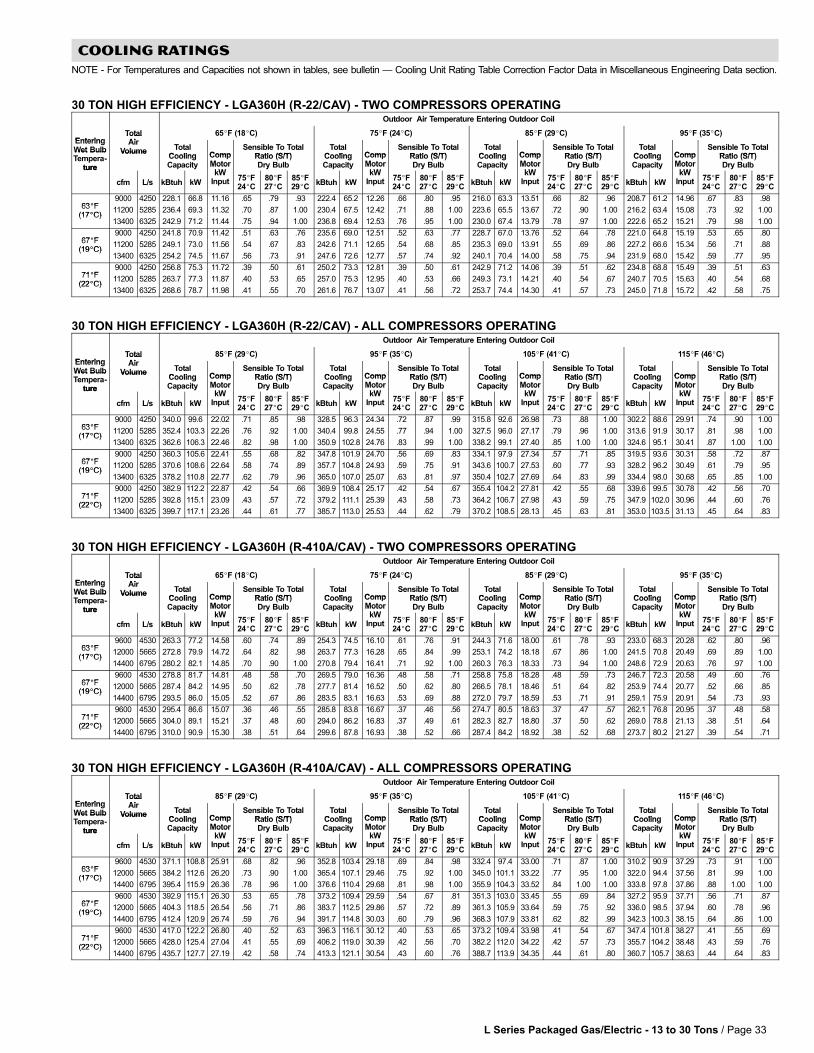
L Series Packaged Gas/Electric − 13 to 30 Tons / Page 33
COOLING RATINGS
NOTE − For Temperatures and Capacities not shown in tables, see bulletin � Cooling Unit Rating Table Correction Factor Data in Miscellaneous Engineering Data section.
30 TON HIGH EFFICIENCY − LGA360H (R−22/CAV) − TWO COMPRESSORS OPERATINGOutdoor Air Temperature Entering Outdoor Coil
EnteringTotalAi
65�F (18�C) 75�F (24�C) 85�F (29�C) 95�F (35�C)EnteringWet Bulb
TotalAir
Volume TotalCooling Comp
Sensible To TotalRatio (S/T)
TotalCooling Comp
Sensible To TotalRatio (S/T)
TotalCooling Comp
Sensible To TotalRatio (S/T)
TotalCooling Comp
Sensible To TotalRatio (S/T)
Wet BulbTempera-
ture
VolumeCoolingCapacity
CompMotor
kW
Ratio (S/T)Dry Bulb
CoolingCapacity
CompMotor
kW
Ratio (S/T)Dry Bulb
CoolingCapacity
CompMotor
kW
Ratio (S/T)Dry Bulb
CoolingCapacity
CompMotor
kW
Ratio (S/T)Dry Bulbture
cfm L/s kBtuh kW
MotorkW
Input 75�F24�C
80�F27�C
85�F29�C
kBtuh kW
MotorkW
Input 75�F24�C
80�F27�C
85�F29�C
kBtuh kW
MotorkW
Input 75�F24�C
80�F27�C
85�F29�C
kBtuh kW
MotorkW
Input 75�F24�C
80�F27�C
85�F29�C
63�F9000 4250 228.1 66.8 11.16 .65 .79 .93 222.4 65.2 12.26 .66 .80 .95 216.0 63.3 13.51 .66 .82 .96 208.7 61.2 14.96 .67 .83 .98
63�F(17�C)
11200 5285 236.4 69.3 11.32 .70 .87 1.00 230.4 67.5 12.42 .71 .88 1.00 223.6 65.5 13.67 .72 .90 1.00 216.2 63.4 15.08 .73 .92 1.00(17�C)
13400 6325 242.9 71.2 11.44 .75 .94 1.00 236.8 69.4 12.53 .76 .95 1.00 230.0 67.4 13.79 .78 .97 1.00 222.6 65.2 15.21 .79 .98 1.00
67�F9000 4250 241.8 70.9 11.42 .51 .63 .76 235.6 69.0 12.51 .52 .63 .77 228.7 67.0 13.76 .52 .64 .78 221.0 64.8 15.19 .53 .65 .80
67�F(19�C)
11200 5285 249.1 73.0 11.56 .54 .67 .83 242.6 71.1 12.65 .54 .68 .85 235.3 69.0 13.91 .55 .69 .86 227.2 66.6 15.34 .56 .71 .88(19�C)
13400 6325 254.2 74.5 11.67 .56 .73 .91 247.6 72.6 12.77 .57 .74 .92 240.1 70.4 14.00 .58 .75 .94 231.9 68.0 15.42 .59 .77 .95
71�F9000 4250 256.8 75.3 11.72 .39 .50 .61 250.2 73.3 12.81 .39 .50 .61 242.9 71.2 14.06 .39 .51 .62 234.8 68.8 15.49 .39 .51 .63
71�F(22�C)
11200 5285 263.7 77.3 11.87 .40 .53 .65 257.0 75.3 12.95 .40 .53 .66 249.3 73.1 14.21 .40 .54 .67 240.7 70.5 15.63 .40 .54 .68(22�C)
13400 6325 268.6 78.7 11.98 .41 .55 .70 261.6 76.7 13.07 .41 .56 .72 253.7 74.4 14.30 .41 .57 .73 245.0 71.8 15.72 .42 .58 .75
30 TON HIGH EFFICIENCY − LGA360H (R−22/CAV) − ALL COMPRESSORS OPERATINGOutdoor Air Temperature Entering Outdoor Coil
EnteringTotalAi
85�F (29�C) 95�F (35�C) 105�F (41�C) 115�F (46�C)EnteringWet Bulb
TotalAir
Volume TotalCooling Comp
Sensible To TotalRatio (S/T)
TotalCooling Comp
Sensible To TotalRatio (S/T)
TotalCooling Comp
Sensible To TotalRatio (S/T)
TotalCooling Comp
Sensible To TotalRatio (S/T)
Wet BulbTempera-
ture
VolumeCoolingCapacity
CompMotor
kW
Ratio (S/T)Dry Bulb
CoolingCapacity
CompMotor
kW
Ratio (S/T)Dry Bulb
CoolingCapacity
CompMotor
kW
Ratio (S/T)Dry Bulb
CoolingCapacity
CompMotor
kW
Ratio (S/T)Dry Bulbture
cfm L/s kBtuh kW
MotorkW
Input 75�F24�C
80�F27�C
85�F29�C
kBtuh kW
MotorkW
Input 75�F24�C
80�F27�C
85�F29�C
kBtuh kW
MotorkW
Input 75�F24�C
80�F27�C
85�F29�C
kBtuh kW
MotorkW
Input 75�F24�C
80�F27�C
85�F29�C
63�F9000 4250 340.0 99.6 22.02 .71 .85 .98 328.5 96.3 24.34 .72 .87 .99 315.8 92.6 26.98 .73 .88 1.00 302.2 88.6 29.91 .74 .90 1.00
63�F(17�C)
11200 5285 352.4 103.3 22.26 .76 .92 1.00 340.4 99.8 24.55 .77 .94 1.00 327.5 96.0 27.17 .79 .96 1.00 313.6 91.9 30.17 .81 .98 1.00(17�C)
13400 6325 362.6 106.3 22.46 .82 .98 1.00 350.9 102.8 24.76 .83 .99 1.00 338.2 99.1 27.40 .85 1.00 1.00 324.6 95.1 30.41 .87 1.00 1.00
67�F9000 4250 360.3 105.6 22.41 .55 .68 .82 347.8 101.9 24.70 .56 .69 .83 334.1 97.9 27.34 .57 .71 .85 319.5 93.6 30.31 .58 .72 .87
67�F(19�C)
11200 5285 370.6 108.6 22.64 .58 .74 .89 357.7 104.8 24.93 .59 .75 .91 343.6 100.7 27.53 .60 .77 .93 328.2 96.2 30.49 .61 .79 .95(19�C)
13400 6325 378.2 110.8 22.77 .62 .79 .96 365.0 107.0 25.07 .63 .81 .97 350.4 102.7 27.69 .64 .83 .99 334.4 98.0 30.68 .65 .85 1.00
71�F9000 4250 382.9 112.2 22.87 .42 .54 .66 369.9 108.4 25.17 .42 .54 .67 355.4 104.2 27.81 .42 .55 .68 339.6 99.5 30.78 .42 .56 .70
71�F(22�C)
11200 5285 392.8 115.1 23.09 .43 .57 .72 379.2 111.1 25.39 .43 .58 .73 364.2 106.7 27.98 .43 .59 .75 347.9 102.0 30.96 .44 .60 .76(22�C)
13400 6325 399.7 117.1 23.26 .44 .61 .77 385.7 113.0 25.53 .44 .62 .79 370.2 108.5 28.13 .45 .63 .81 353.0 103.5 31.13 .45 .64 .83
30 TON HIGH EFFICIENCY − LGA360H (R−410A/CAV) − TWO COMPRESSORS OPERATINGOutdoor Air Temperature Entering Outdoor Coil
EnteringTotalAi
65�F (18�C) 75�F (24�C) 85�F (29�C) 95�F (35�C)EnteringWet Bulb
TotalAir
Volume TotalCooling Comp
Sensible To TotalRatio (S/T)
TotalCooling Comp
Sensible To TotalRatio (S/T)
TotalCooling Comp
Sensible To TotalRatio (S/T)
TotalCooling Comp
Sensible To TotalRatio (S/T)
Wet BulbTempera-
ture
VolumeCoolingCapacity
CompMotor
kW
Ratio (S/T)Dry Bulb
CoolingCapacity
CompMotor
kW
Ratio (S/T)Dry Bulb
CoolingCapacity
CompMotor
kW
Ratio (S/T)Dry Bulb
CoolingCapacity
CompMotor
kW
Ratio (S/T)Dry Bulbture
cfm L/s kBtuh kW
MotorkW
Input 75�F24�C
80�F27�C
85�F29�C
kBtuh kW
MotorkW
Input 75�F24�C
80�F27�C
85�F29�C
kBtuh kW
MotorkW
Input 75�F24�C
80�F27�C
85�F29�C
kBtuh kW
MotorkW
Input 75�F24�C
80�F27�C
85�F29�C
63�F9600 4530 263.3 77.2 14.58 .60 .74 .89 254.3 74.5 16.10 .61 .76 .91 244.3 71.6 18.00 .61 .78 .93 233.0 68.3 20.28 .62 .80 .96
63�F(17�C)
12000 5665 272.8 79.9 14.72 .64 .82 .98 263.7 77.3 16.28 .65 .84 .99 253.1 74.2 18.18 .67 .86 1.00 241.5 70.8 20.49 .69 .89 1.00(17�C)
14400 6795 280.2 82.1 14.85 .70 .90 1.00 270.8 79.4 16.41 .71 .92 1.00 260.3 76.3 18.33 .73 .94 1.00 248.6 72.9 20.63 .76 .97 1.00
67�F9600 4530 278.8 81.7 14.81 .48 .58 .70 269.5 79.0 16.36 .48 .58 .71 258.8 75.8 18.28 .48 .59 .73 246.7 72.3 20.58 .49 .60 .76
67�F(19�C)
12000 5665 287.4 84.2 14.95 .50 .62 .78 277.7 81.4 16.52 .50 .62 .80 266.5 78.1 18.46 .51 .64 .82 253.9 74.4 20.77 .52 .66 .85(19�C)
14400 6795 293.5 86.0 15.05 .52 .67 .86 283.5 83.1 16.63 .53 .69 .88 272.0 79.7 18.59 .53 .71 .91 259.1 75.9 20.91 .54 .73 .93
71�F9600 4530 295.4 86.6 15.07 .36 .46 .55 285.8 83.8 16.67 .37 .46 .56 274.7 80.5 18.63 .37 .47 .57 262.1 76.8 20.95 .37 .48 .58
71�F(22�C)
12000 5665 304.0 89.1 15.21 .37 .48 .60 294.0 86.2 16.83 .37 .49 .61 282.3 82.7 18.80 .37 .50 .62 269.0 78.8 21.13 .38 .51 .64(22�C)
14400 6795 310.0 90.9 15.30 .38 .51 .64 299.6 87.8 16.93 .38 .52 .66 287.4 84.2 18.92 .38 .52 .68 273.7 80.2 21.27 .39 .54 .71
30 TON HIGH EFFICIENCY − LGA360H (R−410A/CAV) − ALL COMPRESSORS OPERATINGOutdoor Air Temperature Entering Outdoor Coil
EnteringTotalAi
85�F (29�C) 95�F (35�C) 105�F (41�C) 115�F (46�C)EnteringWet Bulb
TotalAir
Volume TotalCooling Comp
Sensible To TotalRatio (S/T)
TotalCooling Comp
Sensible To TotalRatio (S/T)
TotalCooling Comp
Sensible To TotalRatio (S/T)
TotalCooling Comp
Sensible To TotalRatio (S/T)
Wet BulbTempera-
ture
VolumeCoolingCapacity
CompMotor
kW
Ratio (S/T)Dry Bulb
CoolingCapacity
CompMotor
kW
Ratio (S/T)Dry Bulb
CoolingCapacity
CompMotor
kW
Ratio (S/T)Dry Bulb
CoolingCapacity
CompMotor
kW
Ratio (S/T)Dry Bulbture
cfm L/s kBtuh kW
MotorkW
Input 75�F24�C
80�F27�C
85�F29�C
kBtuh kW
MotorkW
Input 75�F24�C
80�F27�C
85�F29�C
kBtuh kW
MotorkW
Input 75�F24�C
80�F27�C
85�F29�C
kBtuh kW
MotorkW
Input 75�F24�C
80�F27�C
85�F29�C
63�F9600 4530 371.1 108.8 25.91 .68 .82 .96 352.8 103.4 29.18 .69 .84 .98 332.4 97.4 33.00 .71 .87 1.00 310.2 90.9 37.29 .73 .91 1.00
63�F(17�C)
12000 5665 384.2 112.6 26.20 .73 .90 1.00 365.4 107.1 29.46 .75 .92 1.00 345.0 101.1 33.22 .77 .95 1.00 322.0 94.4 37.56 .81 .99 1.00(17�C)
14400 6795 395.4 115.9 26.36 .78 .96 1.00 376.6 110.4 29.68 .81 .98 1.00 355.9 104.3 33.52 .84 1.00 1.00 333.8 97.8 37.86 .88 1.00 1.00
67�F9600 4530 392.9 115.1 26.30 .53 .65 .78 373.2 109.4 29.59 .54 .67 .81 351.3 103.0 33.45 .55 .69 .84 327.2 95.9 37.71 .56 .71 .87
67�F(19�C)
12000 5665 404.3 118.5 26.54 .56 .71 .86 383.7 112.5 29.86 .57 .72 .89 361.3 105.9 33.64 .59 .75 .92 336.0 98.5 37.94 .60 .78 .96(19�C)
14400 6795 412.4 120.9 26.74 .59 .76 .94 391.7 114.8 30.03 .60 .79 .96 368.3 107.9 33.81 .62 .82 .99 342.3 100.3 38.15 .64 .86 1.00
71�F9600 4530 417.0 122.2 26.80 .40 .52 .63 396.3 116.1 30.12 .40 .53 .65 373.2 109.4 33.98 .41 .54 .67 347.4 101.8 38.27 .41 .55 .69
71�F(22�C)
12000 5665 428.0 125.4 27.04 .41 .55 .69 406.2 119.0 30.39 .42 .56 .70 382.2 112.0 34.22 .42 .57 .73 355.7 104.2 38.48 .43 .59 .76(22�C)
14400 6795 435.7 127.7 27.19 .42 .58 .74 413.3 121.1 30.54 .43 .60 .76 388.7 113.9 34.35 .44 .61 .80 360.7 105.7 38.63 .44 .64 .83
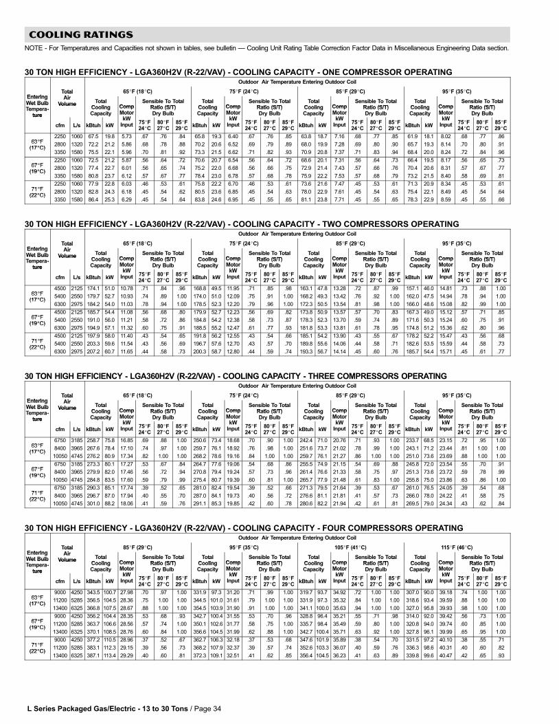
L Series Packaged Gas/Electric − 13 to 30 Tons / Page 34
COOLING RATINGS
NOTE − For Temperatures and Capacities not shown in tables, see bulletin � Cooling Unit Rating Table Correction Factor Data in Miscellaneous Engineering Data section.
30 TON HIGH EFFICIENCY − LGA360H2V (R−22/VAV) − COOLING CAPACITY − ONE COMPRESSOR OPERATINGOutdoor Air Temperature Entering Outdoor Coil
EnteringTotalAi
65�F (18�C) 75�F (24�C) 85�F (29�C) 95�F (35�C)EnteringWet Bulb
TotalAir
Volume TotalCooling Comp
Sensible To TotalRatio (S/T)
TotalCooling Comp
Sensible To TotalRatio (S/T)
TotalCooling Comp
Sensible To TotalRatio (S/T)
TotalCooling Comp
Sensible To TotalRatio (S/T)
Wet BulbTempera-
ture
VolumeCoolingCapacity
CompMotor
kW
Ratio (S/T)Dry Bulb
CoolingCapacity
CompMotor
kW
Ratio (S/T)Dry Bulb
CoolingCapacity
CompMotor
kW
Ratio (S/T)Dry Bulb
CoolingCapacity
CompMotor
kW
Ratio (S/T)Dry Bulbture
cfm L/s kBtuh kW
MotorkW
Input 75�F24�C
80�F27�C
85�F29�C
kBtuh kW
MotorkW
Input 75�F24�C
80�F27�C
85�F29�C
kBtuh kW
MotorkW
Input 75�F24�C
80�F27�C
85�F29�C
kBtuh kW
MotorkW
Input 75�F24�C
80�F27�C
85�F29�C
63�F2250 1060 67.5 19.8 5.73 .67 .76 .84 65.8 19.3 6.40 .67 .76 .85 63.8 18.7 7.16 .68 .77 .85 61.9 18.1 8.02 .68 .77 .86
63�F(17�C)
2800 1320 72.2 21.2 5.86 .68 .78 .88 70.2 20.6 6.52 .69 .79 .89 68.0 19.9 7.28 .69 .80 .90 65.7 19.3 8.14 .70 .80 .91(17�C)
3350 1580 75.5 22.1 5.96 .70 .81 .92 73.3 21.5 6.62 .71 .82 .93 70.9 20.8 7.37 .71 .83 .94 68.4 20.0 8.24 .72 .84 .96
67�F2250 1060 72.5 21.2 5.87 .56 .64 .72 70.6 20.7 6.54 .56 .64 .72 68.6 20.1 7.31 .56 .64 .73 66.4 19.5 8.17 .56 .65 .73
67�F(19�C)
2800 1320 77.4 22.7 6.01 .56 .65 .74 75.2 22.0 6.68 .56 .66 .75 72.9 21.4 7.43 .57 .66 .76 70.4 20.6 8.31 .57 .67 .77(19�C)
3350 1580 80.8 23.7 6.12 .57 .67 .77 78.4 23.0 6.78 .57 .68 .78 75.9 22.2 7.53 .57 .68 .79 73.2 21.5 8.40 .58 .69 .81
71�F2250 1060 77.9 22.8 6.03 .46 .53 .61 75.8 22.2 6.70 .46 .53 .61 73.6 21.6 7.47 .45 .53 .61 71.3 20.9 8.34 .45 .53 .61
71�F(22�C)
2800 1320 82.8 24.3 6.18 .45 .54 .62 80.5 23.6 6.85 .45 .54 .63 78.0 22.9 7.61 .45 .54 .63 75.4 22.1 8.49 .45 .54 .64(22�C)
3350 1580 86.4 25.3 6.29 .45 .54 .64 83.8 24.6 6.95 .45 .55 .65 81.1 23.8 7.71 .45 .55 .65 78.3 22.9 8.59 .45 .55 .66
30 TON HIGH EFFICIENCY − LGA360H2V (R−22/VAV) − COOLING CAPACITY − TWO COMPRESSORS OPERATINGOutdoor Air Temperature Entering Outdoor Coil
EnteringTotalAi
65�F (18�C) 75�F (24�C) 85�F (29�C) 95�F (35�C)EnteringWet Bulb
TotalAir
Volume TotalCooling Comp
Sensible To TotalRatio (S/T)
TotalCooling Comp
Sensible To TotalRatio (S/T)
TotalCooling Comp
Sensible To TotalRatio (S/T)
TotalCooling Comp
Sensible To TotalRatio (S/T)
Wet BulbTempera-
ture
VolumeCoolingCapacity
CompMotor
kW
Ratio (S/T)Dry Bulb
CoolingCapacity
CompMotor
kW
Ratio (S/T)Dry Bulb
CoolingCapacity
CompMotor
kW
Ratio (S/T)Dry Bulb
CoolingCapacity
CompMotor
kW
Ratio (S/T)Dry Bulbture
cfm L/s kBtuh kW
MotorkW
Input 75�F24�C
80�F27�C
85�F29�C
kBtuh kW
MotorkW
Input 75�F24�C
80�F27�C
85�F29�C
kBtuh kW
MotorkW
Input 75�F24�C
80�F27�C
85�F29�C
kBtuh kW
MotorkW
Input 75�F24�C
80�F27�C
85�F29�C
63�F4500 2125 174.1 51.0 10.78 .71 .84 .96 168.8 49.5 11.95 .71 .85 .98 163.1 47.8 13.28 .72 .87 .99 157.1 46.0 14.81 .73 .88 1.00
63�F(17�C)
5400 2550 179.7 52.7 10.93 .74 .89 1.00 174.0 51.0 12.09 .75 .91 1.00 168.2 49.3 13.42 .76 .92 1.00 162.0 47.5 14.94 .78 .94 1.00(17�C)
6300 2975 184.2 54.0 11.03 .78 .94 1.00 178.5 52.3 12.20 .79 .96 1.00 172.3 50.5 13.54 .81 .98 1.00 166.0 48.6 15.08 .82 .99 1.00
67�F4500 2125 185.7 54.4 11.08 .56 .68 .80 179.9 52.7 12.23 .56 .69 .82 173.8 50.9 13.57 .57 .70 .83 167.3 49.0 15.12 .57 .71 .85
67�F(19�C)
5400 2550 191.0 56.0 11.21 .58 .72 .86 184.8 54.2 12.38 .58 .73 .87 178.3 52.3 13.70 .59 .74 .89 171.6 50.3 15.24 .60 .75 .91(19�C)
6300 2975 194.9 57.1 11.32 .60 .75 .91 188.5 55.2 12.47 .61 .77 .93 181.8 53.3 13.81 .61 .78 .95 174.8 51.2 15.36 .62 .80 .96
71�F4500 2125 197.9 58.0 11.40 .43 .54 .65 191.8 56.2 12.55 .43 .54 .66 185.1 54.2 13.90 .43 .55 .67 178.2 52.2 15.47 .43 .56 .68
71�F(22�C)
5400 2550 203.3 59.6 11.54 .43 .56 .69 196.7 57.6 12.70 .43 .57 .70 189.8 55.6 14.06 .44 .58 .71 182.6 53.5 15.59 .44 .58 .73(22�C)
6300 2975 207.2 60.7 11.65 .44 .58 .73 200.3 58.7 12.80 .44 .59 .74 193.3 56.7 14.14 .45 .60 .76 185.7 54.4 15.71 .45 .61 .77
30 TON HIGH EFFICIENCY − LGA360H2V (R−22/VAV) − COOLING CAPACITY − THREE COMPRESSORS OPERATINGOutdoor Air Temperature Entering Outdoor Coil
EnteringTotalAi
65�F (18�C) 75�F (24�C) 85�F (29�C) 95�F (35�C)EnteringWet Bulb
TotalAir
Volume TotalCooling Comp
Sensible To TotalRatio (S/T)
TotalCooling Comp
Sensible To TotalRatio (S/T)
TotalCooling Comp
Sensible To TotalRatio (S/T)
TotalCooling Comp
Sensible To TotalRatio (S/T)
Wet BulbTempera-
ture
VolumeCoolingCapacity
CompMotor
kW
Ratio (S/T)Dry Bulb
CoolingCapacity
CompMotor
kW
Ratio (S/T)Dry Bulb
CoolingCapacity
CompMotor
kW
Ratio (S/T)Dry Bulb
CoolingCapacity
CompMotor
kW
Ratio (S/T)Dry Bulbture
cfm L/s kBtuh kW
MotorkW
Input 75�F24�C
80�F27�C
85�F29�C
kBtuh kW
MotorkW
Input 75�F24�C
80�F27�C
85�F29�C
kBtuh kW
MotorkW
Input 75�F24�C
80�F27�C
85�F29�C
kBtuh kW
MotorkW
Input 75�F24�C
80�F27�C
85�F29�C
63�F6750 3185 258.7 75.8 16.85 .69 .88 1.00 250.6 73.4 18.68 .70 .90 1.00 242.4 71.0 20.76 .71 .93 1.00 233.7 68.5 23.15 .72 .95 1.00
63�F(17�C)
8400 3965 267.6 78.4 17.10 .74 .97 1.00 259.7 76.1 18.92 .76 .98 1.00 251.6 73.7 21.02 .78 .99 1.00 243.1 71.2 23.44 .81 1.00 1.00(17�C)
10050 4745 276.2 80.9 17.34 .82 1.00 1.00 268.2 78.6 19.16 .84 1.00 1.00 259.7 76.1 21.27 .86 1.00 1.00 251.0 73.6 23.69 .88 1.00 1.00
67�F6750 3185 273.3 80.1 17.27 .53 .67 .84 264.7 77.6 19.06 .54 .68 .86 255.5 74.9 21.15 .54 .69 .88 245.8 72.0 23.54 .55 .70 .91
67�F(19�C)
8400 3965 279.9 82.0 17.46 .56 .72 .94 270.8 79.4 19.24 .57 .73 .96 261.4 76.6 21.33 .58 .75 .97 251.3 73.6 23.72 .59 .78 .99(19�C)
10050 4745 284.8 83.5 17.60 .59 .79 .99 275.4 80.7 19.39 .60 .81 1.00 265.7 77.9 21.48 .61 .83 1.00 255.8 75.0 23.86 .63 .86 1.00
71�F6750 3185 290.3 85.1 17.74 .39 .52 .65 281.0 82.4 19.54 .39 .52 .66 271.3 79.5 21.64 .39 .53 .67 261.0 76.5 24.05 .39 .54 .68
71�F(22�C)
8400 3965 296.7 87.0 17.94 .40 .55 .70 287.0 84.1 19.73 .40 .56 .72 276.6 81.1 21.81 .41 .57 .73 266.0 78.0 24.22 .41 .58 .75(22�C)
10050 4745 301.0 88.2 18.06 .41 .59 .76 291.1 85.3 19.85 .42 .60 .78 280.6 82.2 21.94 .42 .61 .81 269.5 79.0 24.34 .43 .62 .84
30 TON HIGH EFFICIENCY − LGA360H2V (R−22/VAV) − COOLING CAPACITY − FOUR COMPRESSORS OPERATINGOutdoor Air Temperature Entering Outdoor Coil
EnteringTotalAi
85�F (29�C) 95�F (35�C) 105�F (41�C) 115�F (46�C)EnteringWet Bulb
TotalAir
Volume TotalCooling Comp
Sensible To TotalRatio (S/T)
TotalCooling Comp
Sensible To TotalRatio (S/T)
TotalCooling Comp
Sensible To TotalRatio (S/T)
TotalCooling Comp
Sensible To TotalRatio (S/T)
Wet BulbTempera-
ture
VolumeCoolingCapacity
CompMotor
kW
Ratio (S/T)Dry Bulb
CoolingCapacity
CompMotor
kW
Ratio (S/T)Dry Bulb
CoolingCapacity
CompMotor
kW
Ratio (S/T)Dry Bulb
CoolingCapacity
CompMotor
kW
Ratio (S/T)Dry Bulbture
cfm L/s kBtuh kW
MotorkW
Input 75�F24�C
80�F27�C
85�F29�C
kBtuh kW
MotorkW
Input 75�F24�C
80�F27�C
85�F29�C
kBtuh kW
MotorkW
Input 75�F24�C
80�F27�C
85�F29�C
kBtuh kW
MotorkW
Input 75�F24�C
80�F27�C
85�F29�C
63�F9000 4250 343.5 100.7 27.98 .70 .97 1.00 331.9 97.3 31.20 .71 .99 1.00 319.7 93.7 34.92 .72 1.00 1.00 307.0 90.0 39.18 .74 1.00 1.00
63�F(17�C)
11200 5285 356.5 104.5 28.36 .75 1.00 1.00 344.5 101.0 31.61 .79 1.00 1.00 331.9 97.3 35.32 .84 1.00 1.00 318.6 93.4 39.59 .88 1.00 1.00(17�C)
13400 6325 366.8 107.5 28.67 .88 1.00 1.00 354.5 103.9 31.90 .91 1.00 1.00 341.1 100.0 35.63 .94 1.00 1.00 327.0 95.8 39.93 .98 1.00 1.00
67�F9000 4250 356.2 104.4 28.35 .53 .68 .93 342.7 100.4 31.55 .53 .70 .96 328.8 96.4 35.21 .55 .71 .98 314.0 92.0 39.42 .56 .73 1.00
67�F(19�C)
11200 5285 363.7 106.6 28.56 .57 .74 1.00 350.1 102.6 31.77 .58 .75 1.00 335.7 98.4 35.49 .59 .80 1.00 320.8 94.0 39.74 .60 .85 1.00(19�C)
13400 6325 370.1 108.5 28.76 .60 .84 1.00 356.6 104.5 31.99 .62 .88 1.00 342.7 100.4 35.71 .63 .92 1.00 327.8 96.1 39.99 .65 .95 1.00
71�F9000 4250 377.2 110.5 28.96 .37 .52 .67 362.7 106.3 32.18 .37 .53 .68 347.6 101.9 35.89 .38 .54 .70 331.5 97.2 40.10 .38 .55 .71
71�F(22�C)
11200 5285 383.1 112.3 29.15 .39 .56 .73 368.2 107.9 32.37 .39 .57 .74 352.6 103.3 36.07 .40 .59 .76 336.3 98.6 40.31 .40 .60 .82(22�C)
13400 6325 387.1 113.4 29.29 .40 .60 .81 372.3 109.1 32.51 .41 .62 .85 356.4 104.5 36.23 .41 .63 .89 339.8 99.6 40.47 .42 .65 .93
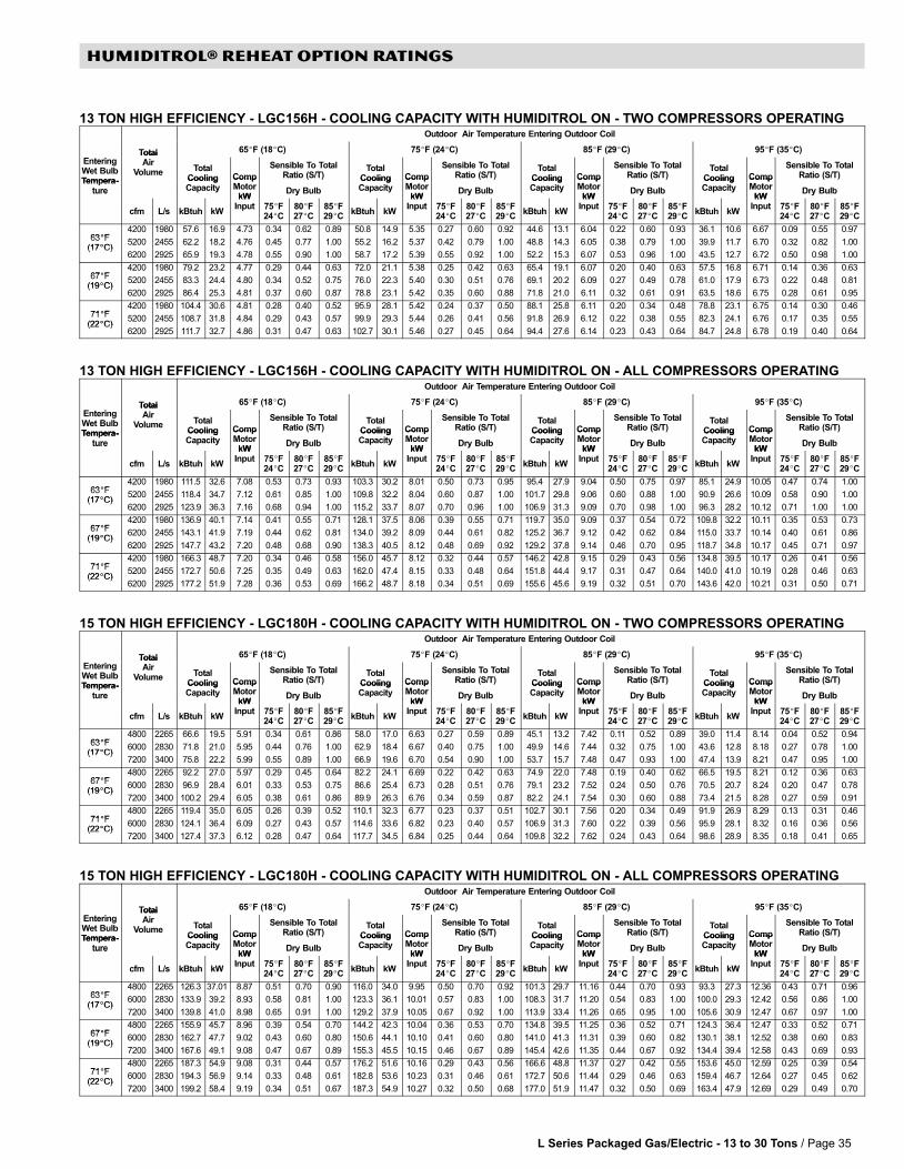
L Series Packaged Gas/Electric − 13 to 30 Tons / Page 35
HUMIDITROL® REHEAT OPTION RATINGS
13 TON HIGH EFFICIENCY − LGC156H − COOLING CAPACITY WITH HUMIDITROL ON − TWO COMPRESSORS OPERATINGOutdoor Air Temperature Entering Outdoor Coil
Total 65�F (18�C) 75�F (24�C) 85�F (29�C) 95�F (35�C)
EnteringWet BulbTempera-
TotalAir
Volume TotalCooling Comp
Sensible To TotalRatio (S/T)
TotalCooling Comp
Sensible To TotalRatio (S/T)
TotalCooling Comp
Sensible To TotalRatio (S/T)
TotalCooling Comp
Sensible To TotalRatio (S/T)
Tempera-ture
CoolingCapacity
CompMotor
kWDry Bulb
CoolingCapacity
CompMotor
kWDry Bulb
CoolingCapacity
CompMotor
kWDry Bulb
CoolingCapacity
CompMotor
kWDry Bulbture
cfm L/s kBtuh kW
kWInput 75�F
24�C80�F27�C
85�F29�C
kBtuh kW
kWInput 75�F
24�C80�F27�C
85�F29�C
kBtuh kW
kWInput 75�F
24�C80�F27�C
85�F29�C
kBtuh kW
kWInput 75�F
24�C80�F27�C
85�F29�C
63�F4200 1980 57.6 16.9 4.73 0.34 0.62 0.89 50.8 14.9 5.35 0.27 0.60 0.92 44.6 13.1 6.04 0.22 0.60 0.93 36.1 10.6 6.67 0.09 0.55 0.97
63�F(17�C)
5200 2455 62.2 18.2 4.76 0.45 0.77 1.00 55.2 16.2 5.37 0.42 0.79 1.00 48.8 14.3 6.05 0.38 0.79 1.00 39.9 11.7 6.70 0.32 0.82 1.00(17�C)
6200 2925 65.9 19.3 4.78 0.55 0.90 1.00 58.7 17.2 5.39 0.55 0.92 1.00 52.2 15.3 6.07 0.53 0.96 1.00 43.5 12.7 6.72 0.50 0.98 1.00
67�F4200 1980 79.2 23.2 4.77 0.29 0.44 0.63 72.0 21.1 5.38 0.25 0.42 0.63 65.4 19.1 6.07 0.20 0.40 0.63 57.5 16.8 6.71 0.14 0.36 0.63
67�F(19�C)
5200 2455 83.3 24.4 4.80 0.34 0.52 0.75 76.0 22.3 5.40 0.30 0.51 0.76 69.1 20.2 6.09 0.27 0.49 0.78 61.0 17.9 6.73 0.22 0.48 0.81(19�C)
6200 2925 86.4 25.3 4.81 0.37 0.60 0.87 78.8 23.1 5.42 0.35 0.60 0.88 71.8 21.0 6.11 0.32 0.61 0.91 63.5 18.6 6.75 0.28 0.61 0.95
71�F4200 1980 104.4 30.6 4.81 0.28 0.40 0.52 95.9 28.1 5.42 0.24 0.37 0.50 88.1 25.8 6.11 0.20 0.34 0.48 78.8 23.1 6.75 0.14 0.30 0.46
71�F(22�C)
5200 2455 108.7 31.8 4.84 0.29 0.43 0.57 99.9 29.3 5.44 0.26 0.41 0.56 91.8 26.9 6.12 0.22 0.38 0.55 82.3 24.1 6.76 0.17 0.35 0.55(22�C)
6200 2925 111.7 32.7 4.86 0.31 0.47 0.63 102.7 30.1 5.46 0.27 0.45 0.64 94.4 27.6 6.14 0.23 0.43 0.64 84.7 24.8 6.78 0.19 0.40 0.64
13 TON HIGH EFFICIENCY − LGC156H − COOLING CAPACITY WITH HUMIDITROL ON − ALL COMPRESSORS OPERATINGOutdoor Air Temperature Entering Outdoor Coil
Total 65�F (18�C) 75�F (24�C) 85�F (29�C) 95�F (35�C)
EnteringWet BulbTempera-
TotalAir
Volume TotalCooling Comp
Sensible To TotalRatio (S/T)
TotalCooling Comp
Sensible To TotalRatio (S/T)
TotalCooling Comp
Sensible To TotalRatio (S/T)
TotalCooling Comp
Sensible To TotalRatio (S/T)
Tempera-ture
CoolingCapacity
CompMotor
kWDry Bulb
CoolingCapacity
CompMotor
kWDry Bulb
CoolingCapacity
CompMotor
kWDry Bulb
CoolingCapacity
CompMotor
kWDry Bulbture
cfm L/s kBtuh kW
kWInput 75�F
24�C80�F27�C
85�F29�C
kBtuh kW
kWInput 75�F
24�C80�F27�C
85�F29�C
kBtuh kW
kWInput 75�F
24�C80�F27�C
85�F29�C
kBtuh kW
kWInput 75�F
24�C80�F27�C
85�F29�C
63�F4200 1980 111.5 32.6 7.08 0.53 0.73 0.93 103.3 30.2 8.01 0.50 0.73 0.95 95.4 27.9 9.04 0.50 0.75 0.97 85.1 24.9 10.05 0.47 0.74 1.00
63�F(17�C)
5200 2455 118.4 34.7 7.12 0.61 0.85 1.00 109.8 32.2 8.04 0.60 0.87 1.00 101.7 29.8 9.06 0.60 0.88 1.00 90.9 26.6 10.09 0.58 0.90 1.00(17�C)
6200 2925 123.9 36.3 7.16 0.68 0.94 1.00 115.2 33.7 8.07 0.70 0.96 1.00 106.9 31.3 9.09 0.70 0.98 1.00 96.3 28.2 10.12 0.71 1.00 1.00
67�F4200 1980 136.9 40.1 7.14 0.41 0.55 0.71 128.1 37.5 8.06 0.39 0.55 0.71 119.7 35.0 9.09 0.37 0.54 0.72 109.8 32.2 10.11 0.35 0.53 0.73
67�F(19�C)
6200 2455 143.1 41.9 7.19 0.44 0.62 0.81 134.0 39.2 8.09 0.44 0.61 0.82 125.2 36.7 9.12 0.42 0.62 0.84 115.0 33.7 10.14 0.40 0.61 0.86(19�C)
6200 2925 147.7 43.2 7.20 0.48 0.68 0.90 138.3 40.5 8.12 0.48 0.69 0.92 129.2 37.8 9.14 0.46 0.70 0.95 118.7 34.8 10.17 0.45 0.71 0.97
71�F4200 1980 166.3 48.7 7.20 0.34 0.46 0.58 156.0 45.7 8.12 0.32 0.44 0.57 146.2 42.8 9.15 0.29 0.43 0.56 134.8 39.5 10.17 0.26 0.41 0.56
71�F(22�C)
5200 2455 172.7 50.6 7.25 0.35 0.49 0.63 162.0 47.4 8.15 0.33 0.48 0.64 151.8 44.4 9.17 0.31 0.47 0.64 140.0 41.0 10.19 0.28 0.46 0.63(22�C)
6200 2925 177.2 51.9 7.28 0.36 0.53 0.69 166.2 48.7 8.18 0.34 0.51 0.69 155.6 45.6 9.19 0.32 0.51 0.70 143.6 42.0 10.21 0.31 0.50 0.71
15 TON HIGH EFFICIENCY − LGC180H − COOLING CAPACITY WITH HUMIDITROL ON − TWO COMPRESSORS OPERATINGOutdoor Air Temperature Entering Outdoor Coil
Total 65�F (18�C) 75�F (24�C) 85�F (29�C) 95�F (35�C)
EnteringWet BulbTempera-
TotalAir
Volume TotalCooling Comp
Sensible To TotalRatio (S/T)
TotalCooling Comp
Sensible To TotalRatio (S/T)
TotalCooling Comp
Sensible To TotalRatio (S/T)
TotalCooling Comp
Sensible To TotalRatio (S/T)
Tempera-ture
CoolingCapacity
CompMotor
kWDry Bulb
CoolingCapacity
CompMotor
kWDry Bulb
CoolingCapacity
CompMotor
kWDry Bulb
CoolingCapacity
CompMotor
kWDry Bulbture
cfm L/s kBtuh kW
kWInput 75�F
24�C80�F27�C
85�F29�C
kBtuh kW
kWInput 75�F
24�C80�F27�C
85�F29�C
kBtuh kW
kWInput 75�F
24�C80�F27�C
85�F29�C
kBtuh kW
kWInput 75�F
24�C80�F27�C
85�F29�C
63�F4800 2265 66.6 19.5 5.91 0.34 0.61 0.86 58.0 17.0 6.63 0.27 0.59 0.89 45.1 13.2 7.42 0.11 0.52 0.89 39.0 11.4 8.14 0.04 0.52 0.94
63�F(17�C)
6000 2830 71.8 21.0 5.95 0.44 0.76 1.00 62.9 18.4 6.67 0.40 0.75 1.00 49.9 14.6 7.44 0.32 0.75 1.00 43.6 12.8 8.18 0.27 0.78 1.00(17�C)
7200 3400 75.8 22.2 5.99 0.55 0.89 1.00 66.9 19.6 6.70 0.54 0.90 1.00 53.7 15.7 7.48 0.47 0.93 1.00 47.4 13.9 8.21 0.47 0.95 1.00
67�F4800 2265 92.2 27.0 5.97 0.29 0.45 0.64 82.2 24.1 6.69 0.22 0.42 0.63 74.9 22.0 7.48 0.19 0.40 0.62 66.5 19.5 8.21 0.12 0.36 0.63
67�F(19�C)
6000 2830 96.9 28.4 6.01 0.33 0.53 0.75 86.6 25.4 6.73 0.28 0.51 0.76 79.1 23.2 7.52 0.24 0.50 0.76 70.5 20.7 8.24 0.20 0.47 0.78(19�C)
7200 3400 100.2 29.4 6.05 0.38 0.61 0.86 89.9 26.3 6.76 0.34 0.59 0.87 82.2 24.1 7.54 0.30 0.60 0.88 73.4 21.5 8.28 0.27 0.59 0.91
71�F4800 2265 119.4 35.0 6.05 0.26 0.39 0.52 110.1 32.3 6.77 0.23 0.37 0.51 102.7 30.1 7.56 0.20 0.34 0.49 91.9 26.9 8.29 0.13 0.31 0.46
71�F(22�C)
6000 2830 124.1 36.4 6.09 0.27 0.43 0.57 114.6 33.6 6.82 0.23 0.40 0.57 106.9 31.3 7.60 0.22 0.39 0.56 95.9 28.1 8.32 0.16 0.36 0.56(22�C)
7200 3400 127.4 37.3 6.12 0.28 0.47 0.64 117.7 34.5 6.84 0.25 0.44 0.64 109.8 32.2 7.62 0.24 0.43 0.64 98.6 28.9 8.35 0.18 0.41 0.65
15 TON HIGH EFFICIENCY − LGC180H − COOLING CAPACITY WITH HUMIDITROL ON − ALL COMPRESSORS OPERATINGOutdoor Air Temperature Entering Outdoor Coil
Total 65�F (18�C) 75�F (24�C) 85�F (29�C) 95�F (35�C)
EnteringWet BulbTempera-
TotalAir
Volume TotalCooling Comp
Sensible To TotalRatio (S/T)
TotalCooling Comp
Sensible To TotalRatio (S/T)
TotalCooling Comp
Sensible To TotalRatio (S/T)
TotalCooling Comp
Sensible To TotalRatio (S/T)
Tempera-ture
CoolingCapacity
CompMotor
kWDry Bulb
CoolingCapacity
CompMotor
kWDry Bulb
CoolingCapacity
CompMotor
kWDry Bulb
CoolingCapacity
CompMotor
kWDry Bulbture
cfm L/s kBtuh kW
kWInput 75�F
24�C80�F27�C
85�F29�C
kBtuh kW
kWInput 75�F
24�C80�F27�C
85�F29�C
kBtuh kW
kWInput 75�F
24�C80�F27�C
85�F29�C
kBtuh kW
kWInput 75�F
24�C80�F27�C
85�F29�C
63�F4800 2265 126.3 37.01 8.87 0.51 0.70 0.90 116.0 34.0 9.95 0.50 0.70 0.92 101.3 29.7 11.16 0.44 0.70 0.93 93.3 27.3 12.36 0.43 0.71 0.96
63�F(17�C)
6000 2830 133.9 39.2 8.93 0.58 0.81 1.00 123.3 36.1 10.01 0.57 0.83 1.00 108.3 31.7 11.20 0.54 0.83 1.00 100.0 29.3 12.42 0.56 0.86 1.00(17�C)
7200 3400 139.8 41.0 8.98 0.65 0.91 1.00 129.2 37.9 10.05 0.67 0.92 1.00 113.9 33.4 11.26 0.65 0.95 1.00 105.6 30.9 12.47 0.67 0.97 1.00
67�F4800 2265 155.9 45.7 8.96 0.39 0.54 0.70 144.2 42.3 10.04 0.36 0.53 0.70 134.8 39.5 11.25 0.36 0.52 0.71 124.3 36.4 12.47 0.33 0.52 0.71
67�F(19�C)
6000 2830 162.7 47.7 9.02 0.43 0.60 0.80 150.6 44.1 10.10 0.41 0.60 0.80 141.0 41.3 11.31 0.39 0.60 0.82 130.1 38.1 12.52 0.38 0.60 0.83(19�C)
7200 3400 167.6 49.1 9.08 0.47 0.67 0.89 155.3 45.5 10.15 0.46 0.67 0.89 145.4 42.6 11.35 0.44 0.67 0.92 134.4 39.4 12.58 0.43 0.69 0.93
71�F4800 2265 187.3 54.9 9.08 0.31 0.44 0.57 176.2 51.6 10.16 0.29 0.43 0.56 166.6 48.8 11.37 0.27 0.42 0.55 153.6 45.0 12.59 0.25 0.39 0.54
71�F(22�C)
6000 2830 194.3 56.9 9.14 0.33 0.48 0.61 182.8 53.6 10.23 0.31 0.46 0.61 172.7 50.6 11.44 0.29 0.46 0.63 159.4 46.7 12.64 0.27 0.45 0.62(22�C)
7200 3400 199.2 58.4 9.19 0.34 0.51 0.67 187.3 54.9 10.27 0.32 0.50 0.68 177.0 51.9 11.47 0.32 0.50 0.69 163.4 47.9 12.69 0.29 0.49 0.70
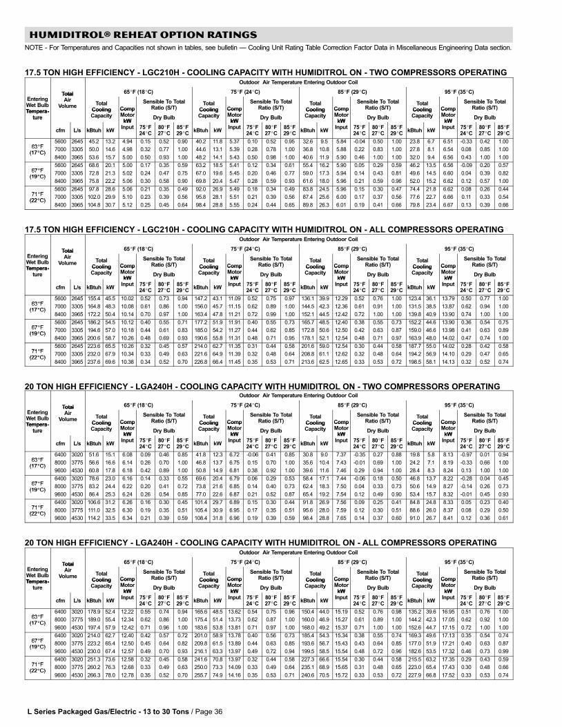
L Series Packaged Gas/Electric − 13 to 30 Tons / Page 36
HUMIDITROL® REHEAT OPTION RATINGS
NOTE − For Temperatures and Capacities not shown in tables, see bulletin � Cooling Unit Rating Table Correction Factor Data in Miscellaneous Engineering Data section.
17.5 TON HIGH EFFICIENCY − LGC210H − COOLING CAPACITY WITH HUMIDITROL ON − TWO COMPRESSORS OPERATINGOutdoor Air Temperature Entering Outdoor Coil
Total 65�F (18�C) 75�F (24�C) 85�F (29�C) 95�F (35�C)
EnteringWet BulbTempera-
TotalAir
Volume TotalCooling Comp
Sensible To TotalRatio (S/T)
TotalCooling Comp
Sensible To TotalRatio (S/T)
TotalCooling Comp
Sensible To TotalRatio (S/T)
TotalCooling Comp
Sensible To TotalRatio (S/T)
Tempera-ture
CoolingCapacity
CompMotor
kWDry Bulb
CoolingCapacity
CompMotor
kWDry Bulb
CoolingCapacity
CompMotor
kWDry Bulb
CoolingCapacity
CompMotor
kWDry Bulbture
cfm L/s kBtuh kW
kWInput 75�F
24�C80�F27�C
85�F29�C
kBtuh kW
kWInput 75�F
24�C80�F27�C
85�F29�C
kBtuh kW
kWInput 75�F
24�C80�F27�C
85�F29�C
kBtuh kW
kWInput 75�F
24�C80�F27�C
85�F29�C
63�F5600 2645 45.2 13.2 4.94 0.15 0.52 0.90 40.2 11.8 5.37 0.10 0.52 0.95 32.6 9.5 5.84 −0.04 0.50 1.00 23.8 6.7 6.51 −0.33 0.42 1.00
63�F(17�C)
7000 3305 50.0 14.6 4.98 0.32 0.77 1.00 44.6 13.1 5.39 0.28 0.78 1.00 36.8 10.8 5.88 0.22 0.83 1.00 27.8 8.1 6.54 0.08 0.85 1.00(17�C)
8400 3965 53.6 15.7 5.00 0.50 0.93 1.00 48.2 14.1 5.43 0.50 0.98 1.00 40.6 11.9 5.90 0.46 1.00 1.00 32.0 9.4 6.56 0.43 1.00 1.00
67�F5600 2645 68.6 20.1 5.00 0.17 0.35 0.59 63.2 18.5 5.41 0.12 0.34 0.61 55.4 16.2 5.90 0.05 0.29 0.59 46.2 13.5 6.56 −0.09 0.20 0.57
67�F(19�C)
7000 3305 72.8 21.3 5.02 0.24 0.47 0.75 67.0 19.6 5.45 0.20 0.46 0.77 59.0 17.3 5.94 0.14 0.43 0.81 49.6 14.5 6.60 0.04 0.39 0.82(19�C)
8400 3965 75.8 22.2 5.06 0.30 0.58 0.90 69.8 20.4 5.47 0.28 0.59 0.93 61.6 18.0 5.96 0.21 0.59 0.96 52.0 15.2 6.62 0.12 0.57 1.00
71�F5600 2645 97.8 28.6 5.06 0.21 0.35 0.49 92.0 26.9 5.49 0.18 0.34 0.49 83.8 24.5 5.96 0.15 0.30 0.47 74.4 21.8 6.62 0.08 0.26 0.44
71�F(22�C)
7000 3305 102.0 29.9 5.10 0.23 0.39 0.56 95.8 28.1 5.51 0.21 0.39 0.56 87.4 25.6 6.00 0.17 0.37 0.56 77.6 22.7 6.66 0.11 0.33 0.54(22�C)
8400 3965 104.8 30.7 5.12 0.25 0.45 0.64 98.4 28.8 5.55 0.24 0.44 0.65 89.8 26.3 6.01 0.19 0.41 0.66 79.8 23.4 6.67 0.13 0.39 0.66
17.5 TON HIGH EFFICIENCY − LGC210H − COOLING CAPACITY WITH HUMIDITROL ON − ALL COMPRESSORS OPERATINGOutdoor Air Temperature Entering Outdoor Coil
Total 65�F (18�C) 75�F (24�C) 85�F (29�C) 95�F (35�C)
EnteringWet BulbTempera-
TotalAir
Volume TotalCooling Comp
Sensible To TotalRatio (S/T)
TotalCooling Comp
Sensible To TotalRatio (S/T)
TotalCooling Comp
Sensible To TotalRatio (S/T)
TotalCooling Comp
Sensible To TotalRatio (S/T)
Tempera-ture
CoolingCapacity
CompMotor
kWDry Bulb
CoolingCapacity
CompMotor
kWDry Bulb
CoolingCapacity
CompMotor
kWDry Bulb
CoolingCapacity
CompMotor
kWDry Bulbture
cfm L/s kBtuh kW
kWInput 75�F
24�C80�F27�C
85�F29�C
kBtuh kW
kWInput 75�F
24�C80�F27�C
85�F29�C
kBtuh kW
kWInput 75�F
24�C80�F27�C
85�F29�C
kBtuh kW
kWInput 75�F
24�C80�F27�C
85�F29�C
63�F5600 2645 155.4 45.5 10.02 0.52 0.73 0.94 147.2 43.1 11.09 0.52 0.75 0.97 136.1 39.9 12.29 0.52 0.76 1.00 123.4 36.1 13.79 0.50 0.77 1.00
63�F(17�C)
7000 3305 164.8 48.3 10.08 0.61 0.86 1.00 156.0 45.7 11.15 0.62 0.89 1.00 144.5 42.3 12.36 0.61 0.91 1.00 131.5 38.5 13.87 0.62 0.94 1.00(17�C)
8400 3965 172.2 50.4 10.14 0.70 0.97 1.00 163.4 47.8 11.21 0.72 0.99 1.00 152.1 44.5 12.42 0.72 1.00 1.00 139.8 40.9 13.90 0.74 1.00 1.00
67�F5600 2645 186.2 54.5 10.12 0.40 0.55 0.71 177.2 51.9 11.91 0.40 0.55 0.73 165.7 48.5 12.40 0.38 0.55 0.73 152.2 44.6 13.90 0.36 0.54 0.75
67�F(19�C)
7000 3305 194.6 57.0 10.18 0.44 0.61 0.83 185.0 54.2 11.27 0.44 0.62 0.85 172.8 50.6 12.50 0.42 0.63 0.87 159.0 46.6 13.98 0.41 0.63 0.89(19�C)
8400 3965 200.6 58.7 10.26 0.48 0.69 0.93 190.6 55.8 11.31 0.48 0.71 0.95 178.1 52.1 12.54 0.48 0.71 0.97 163.9 48.0 14.02 0.47 0.74 1.00
71�F5600 2645 223.6 65.5 10.26 0.32 0.45 0.57 214.0 62.7 11.35 0.31 0.44 0.58 201.6 59.0 12.54 0.30 0.44 0.58 187.7 55.0 14.02 0.28 0.42 0.58
71�F(22�C)
7000 3305 232.0 67.9 10.34 0.33 0.49 0.63 221.6 64.9 11.39 0.32 0.48 0.64 208.8 61.1 12.62 0.32 0.48 0.64 194.2 56.9 14.10 0.29 0.47 0.65(22�C)
8400 3965 237.6 69.6 10.38 0.34 0.52 0.70 226.8 66.4 11.45 0.35 0.53 0.71 213.6 62.5 12.65 0.33 0.53 0.72 198.5 58.1 14.13 0.32 0.52 0.74
20 TON HIGH EFFICIENCY − LGA240H − COOLING CAPACITY WITH HUMIDITROL ON − TWO COMPRESSORS OPERATINGOutdoor Air Temperature Entering Outdoor Coil
Total 65�F (18�C) 75�F (24�C) 85�F (29�C) 95�F (35�C)
EnteringWet BulbTempera-
TotalAir
Volume TotalCooling Comp
Sensible To TotalRatio (S/T)
TotalCooling Comp
Sensible To TotalRatio (S/T)
TotalCooling Comp
Sensible To TotalRatio (S/T)
TotalCooling Comp
Sensible To TotalRatio (S/T)
Tempera-ture
CoolingCapacity
CompMotor
kWDry Bulb
CoolingCapacity
CompMotor
kWDry Bulb
CoolingCapacity
CompMotor
kWDry Bulb
CoolingCapacity
CompMotor
kWDry Bulbture
cfm L/s kBtuh kW
kWInput 75�F
24�C80�F27�C
85�F29�C
kBtuh kW
kWInput 75�F
24�C80�F27�C
85�F29�C
kBtuh kW
kWInput 75�F
24�C80�F27�C
85�F29�C
kBtuh kW
kWInput 75�F
24�C80�F27�C
85�F29�C
63�F6400 3020 51.6 15.1 6.08 0.09 0.46 0.85 41.8 12.3 6.72 −0.06 0.41 0.85 30.8 9.0 7.37 −0.35 0.27 0.88 19.8 5.8 8.13 −0.97 0.01 0.94
63�F(17�C)
8000 3775 56.6 16.6 6.14 0.26 0.70 1.00 46.8 13.7 6.75 0.15 0.70 1.00 35.6 10.4 7.43 −0.01 0.69 1.00 24.2 7.1 8.19 −0.33 0.66 1.00(17�C)
9600 4530 60.8 17.8 6.18 0.42 0.89 1.00 50.8 14.9 6.81 0.38 0.92 1.00 39.6 11.6 7.46 0.29 0.94 1.00 28.4 8.3 8.24 0.13 1.00 1.00
67�F6400 3020 78.6 23.0 6.16 0.14 0.33 0.55 69.6 20.4 6.79 0.06 0.29 0.53 58.4 17.1 7.44 −0.06 0.18 0.50 46.8 13.7 8.22 −0.28 0.04 0.45
67�F(19�C)
8000 3775 83.2 24.4 6.22 0.20 0.41 0.72 73.8 21.6 6.85 0.14 0.40 0.73 62.4 18.3 7.50 0.04 0.33 0.73 50.6 14.9 8.27 −0.14 0.26 0.73(19�C)
9600 4530 86.4 25.3 6.24 0.26 0.54 0.85 77.0 22.6 6.87 0.21 0.52 0.87 65.4 19.2 7.54 0.12 0.49 0.90 53.4 15.7 8.32 −0.01 0.45 0.93
71�F6400 3020 106.6 31.2 6.26 0.16 0.30 0.45 101.4 29.7 6.89 0.15 0.30 0.44 91.8 26.9 7.56 0.09 0.25 0.41 84.8 24.8 8.33 0.05 0.23 0.40
71�F(22�C)
8000 3775 111.0 32.5 6.30 0.19 0.35 0.51 105.4 30.9 6.95 0.17 0.35 0.51 95.6 28.0 7.59 0.12 0.30 0.51 88.6 26.0 8.37 0.08 0.29 0.50(22�C)
9600 4530 114.2 33.5 6.34 0.21 0.39 0.59 108.4 31.8 6.96 0.19 0.39 0.59 98.4 28.8 7.65 0.14 0.37 0.60 91.0 26.7 8.41 0.12 0.36 0.61
20 TON HIGH EFFICIENCY − LGA240H − COOLING CAPACITY WITH HUMIDITROL ON − ALL COMPRESSORS OPERATINGOutdoor Air Temperature Entering Outdoor Coil
Total 65�F (18�C) 75�F (24�C) 85�F (29�C) 95�F (35�C)
EnteringWet BulbTempera-
TotalAir
Volume TotalCooling Comp
Sensible To TotalRatio (S/T)
TotalCooling Comp
Sensible To TotalRatio (S/T)
TotalCooling Comp
Sensible To TotalRatio (S/T)
TotalCooling Comp
Sensible To TotalRatio (S/T)
Tempera-ture
CoolingCapacity
CompMotor
kWDry Bulb
CoolingCapacity
CompMotor
kWDry Bulb
CoolingCapacity
CompMotor
kWDry Bulb
CoolingCapacity
CompMotor
kWDry Bulbture
cfm L/s kBtuh kW
kWInput 75�F
24�C80�F27�C
85�F29�C
kBtuh kW
kWInput 75�F
24�C80�F27�C
85�F29�C
kBtuh kW
kWInput 75�F
24�C80�F27�C
85�F29�C
kBtuh kW
kWInput 75�F
24�C80�F27�C
85�F29�C
63�F6400 3020 178.9 52.4 12.22 0.55 0.74 0.94 165.6 48.5 13.62 0.54 0.75 0.96 150.4 44.0 15.19 0.52 0.76 0.98 135.2 39.6 16.95 0.51 0.76 1.00
63�F(17�C)
8000 3775 189.0 55.4 12.34 0.62 0.86 1.00 175.4 51.4 13.73 0.62 0.87 1.00 160.0 46.9 15.27 0.61 0.89 1.00 144.2 42.3 17.05 0.62 0.92 1.00(17�C)
9600 4530 197.4 57.9 12.42 0.71 0.96 1.00 183.6 53.8 13.81 0.71 0.97 1.00 168.0 49.2 15.37 0.71 1.00 1.00 152.6 44.7 17.15 0.72 1.00 1.00
67�F6400 3020 214.0 62.7 12.40 0.42 0.57 0.72 201.0 58.9 13.78 0.40 0.56 0.73 185.4 54.3 15.34 0.38 0.55 0.74 169.3 49.6 17.13 0.35 0.54 0.74
67�F(19�C)
8000 3775 223.2 65.4 12.50 0.45 0.64 0.82 209.8 61.5 13.89 0.44 0.63 0.85 193.6 56.7 15.43 0.43 0.64 0.85 177.0 51.9 17.21 0.40 0.63 0.87(19�C)
9600 4530 230.0 67.4 12.57 0.49 0.70 0.93 216.1 63.3 13.97 0.49 0.72 0.94 199.5 58.5 15.54 0.48 0.72 0.96 182.6 53.5 17.32 0.46 0.73 0.99
71�F6400 3020 251.3 73.6 12.58 0.32 0.45 0.58 241.6 70.8 13.97 0.32 0.44 0.58 227.3 66.6 15.54 0.30 0.44 0.58 215.5 63.2 17.35 0.29 0.43 0.59
71�F(22�C)
8000 3775 260.2 76.3 12.68 0.33 0.49 0.63 250.0 73.3 14.09 0.33 0.49 0.64 235.1 68.9 15.65 0.31 0.48 0.65 223.0 65.4 17.43 0.30 0.48 0.66(22�C)
9600 4530 266.3 78.0 12.78 0.35 0.52 0.70 255.7 74.9 14.16 0.35 0.53 0.71 240.6 70.5 15.72 0.33 0.53 0.72 227.9 66.8 17.52 0.33 0.53 0.74
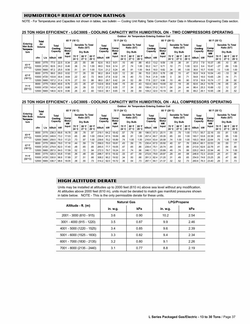
L Series Packaged Gas/Electric − 13 to 30 Tons / Page 37
HUMIDITROL® REHEAT OPTION RATINGS
NOTE − For Temperatures and Capacities not shown in tables, see bulletin � Cooling Unit Rating Table Correction Factor Data in Miscellaneous Engineering Data section.
25 TON HIGH EFFICIENCY − LGC300S − COOLING CAPACITY WITH HUMIDITROL ON − TWO COMPRESSORS OPERATINGOutdoor Air Temperature Entering Outdoor Coil
Total 65�F (18�C) 75�F (24�C) 85�F (29�C) 95�F (35�C)
EnteringWet BulbTempera-
TotalAir
Volume TotalCooling Comp
Sensible To TotalRatio (S/T)
TotalCooling Comp
Sensible To TotalRatio (S/T)
TotalCooling Comp
Sensible To TotalRatio (S/T)
TotalCooling Comp
Sensible To TotalRatio (S/T)
Tempera-ture
CoolingCapacity
CompMotor
kWDry Bulb
CoolingCapacity
CompMotor
kWDry Bulb
CoolingCapacity
CompMotor
kWDry Bulb
CoolingCapacity
CompMotor
kWDry Bulbture
cfm L/s kBtuh kW
kWInput 75�F
24�C80�F27�C
85�F29�C
kBtuh kW
kWInput 75�F
24�C80�F27�C
85�F29�C
kBtuh kW
kWInput 75�F
24�C80�F27�C
85�F29�C
kBtuh kW
kWInput 75�F
24�C80�F27�C
85�F29�C
63�F8000 3775 77.0 22.5 8.34 .25 .55 .88 62.6 18.3 9.01 .10 .49 .88 45.0 13.2 9.59 −.18 .38 .91 27.0 7.9 10.37 −.85 .10 .95
63�F(17�C)
10000 4720 82.6 24.2 8.46 .36 .74 1.00 68.0 19.9 9.14 .27 .74 1.00 50.2 14.7 9.71 .10 .71 1.00 32.0 9.4 10.47 −.27 .69 1.00(17�C)
12000 5665 87.2 25.5 8.56 .51 .91 1.00 72.4 21.2 9.24 .45 .91 1.00 54.6 16.0 9.82 .34 .95 1.00 36.6 10.7 10.60 .13 1.00 1.00
67�F8000 3775 99.0 29.0 8.52 .17 .35 .55 90.2 26.4 9.20 .12 .30 .56 70.0 20.5 9.78 −.08 .15 .47 50.8 14.9 10.54 −.43 −.10 .38
67�F(19�C)
10000 4720 103.8 30.4 8.64 .22 .42 .72 94.8 27.8 9.32 .18 .40 .73 74.4 21.8 9.89 0 .30 .71 54.8 16.0 10.65 −.29 .14 .71(19�C)
12000 5665 107.2 31.4 8.74 .27 .53 .86 98.0 28.7 9.42 .24 .52 .89 77.6 22.7 9.96 .10 .46 .90 57.8 16.9 10.74 −.17 .38 .92
71�F8000 3775 138.8 40.6 8.76 .23 .35 .47 122.6 35.9 9.46 .15 .30 .43 102.4 30.0 10.00 .02 .19 .35 82.6 24.2 10.78 −.16 .05 .25
71�F(22�C)
10000 4720 143.4 42.0 8.88 .24 .39 .53 127.2 37.2 9.55 .17 .34 .50 106.4 31.2 10.11 .04 .24 .44 86.4 25.3 10.88 −.12 .12 .37(22�C)
12000 5665 146.6 42.9 8.96 .26 .43 .60 130.0 38.1 9.65 .19 .39 .59 109.2 32.0 10.19 .08 .31 .56 89.2 26.1 10.95 −.08 .20 .52
25 TON HIGH EFFICIENCY − LGC300S − COOLING CAPACITY WITH HUMIDITROL ON − ALL COMPRESSORS OPERATINGOutdoor Air Temperature Entering Outdoor Coil
Total 65�F (18�C) 75�F (24�C) 85�F (29�C) 95�F (35�C)
EnteringWet BulbTempera-
TotalAir
Volume TotalCooling Comp
Sensible To TotalRatio (S/T)
TotalCooling Comp
Sensible To TotalRatio (S/T)
TotalCooling Comp
Sensible To TotalRatio (S/T)
TotalCooling Comp
Sensible To TotalRatio (S/T)
Tempera-ture
CoolingCapacity
CompMotor
kWDry Bulb
CoolingCapacity
CompMotor
kWDry Bulb
CoolingCapacity
CompMotor
kWDry Bulb
CoolingCapacity
CompMotor
kWDry Bulbture
cfm L/s kBtuh kW
kWInput 75�F
24�C80�F27�C
85�F29�C
kBtuh kW
kWInput 75�F
24�C80�F27�C
85�F29�C
kBtuh kW
kWInput 75�F
24�C80�F27�C
85�F29�C
kBtuh kW
kWInput 75�F
24�C80�F27�C
85�F29�C
63�F8000 3775 238.3 69.8 16.78 .58 .78 .97 219.1 64.2 18.42 .57 .79 .99 196.5 57.3 20.11 .55 .79 1.00 173.1 50.7 22.16 .53 .81 1.00
63�F(17�C)
10000 4720 249.9 73.2 17.03 .65 .88 1.00 230.4 67.5 18.69 .66 .91 1.00 207.4 60.7 20.35 .65 .93 1.00 183.7 53.8 22.38 .63 .95 1.00(17�C)
12000 5665 259.5 76.0 17.23 .73 .97 1.00 239.6 70.2 18.89 .74 1.00 1.00 216.6 63.4 20.58 .74 1.00 1.00 193.3 56.6 22.64 .75 1.00 1.00
67�F8000 3775 269.8 79.0 17.16 .44 .59 .74 256.0 75.0 18.81 .43 .59 .75 230.4 67.5 20.50 .40 .57 .76 205.4 60.1 22.53 .35 .55 .77
67�F(19�C)
10000 4720 279.9 82.0 17.40 .48 .65 .85 265.5 77.7 19.05 .47 .65 .86 239.4 70.1 20.74 .44 .64 .88 213.9 62.6 22.76 .41 .64 .90(19�C)
12000 5665 287.0 84.0 17.59 .52 .72 .94 272.3 79.7 19.24 .51 .74 .96 246.1 72.1 20.89 .49 .74 .99 220.2 64.5 22.94 .46 .74 1.00
71�F8000 3775 320.3 93.8 17.65 .36 .48 .60 298.7 87.5 19.32 .33 .47 .59 272.8 79.9 20.97 .29 .44 .58 246.9 72.3 23.03 .25 .41 .56
71�F(22�C)
10000 4720 330.0 96.6 17.89 .37 .51 .66 308.2 90.2 19.52 .34 .50 .66 281.3 82.4 21.20 .31 .49 .65 254.9 74.6 23.25 .26 .47 .66(22�C)
12000 5665 336.7 98.6 18.05 .38 .55 .73 314.2 92.0 19.72 .36 .54 .73 287.1 84.1 21.37 .32 .52 .73 260.6 76.3 23.40 .29 .51 .73
HIGH ALTITUDE DERATE
Units may be installed at altitudes up to 2000 feet (610 m) above sea level without any modification.
At altitudes above 2000 feet (610 m), units must be derated to match gas manifold pressures shown
in table below. NOTE − This is the only permissible derate for these units.
Altitude ft (m)Natural Gas LPG/Propane
Altitude − ft. (m)in. w.g. kPa in. w.g. kPa
2001 − 3000 (610 − 915) 3.6 0.90 10.2 2.54
3001 − 4000 (915 − 1220) 3.5 0.87 9.9 2.46
4001 − 5000 (1220 − 1525) 3.4 0.85 9.6 2.39
5001 − 6000 (1525 − 1830) 3.3 0.82 9.4 2.34
6001 − 7000 (1830 − 2135) 3.2 0.80 9.1 2.26
7001 − 8000 (2135 − 2440) 3.1 0.77 8.8 2.19
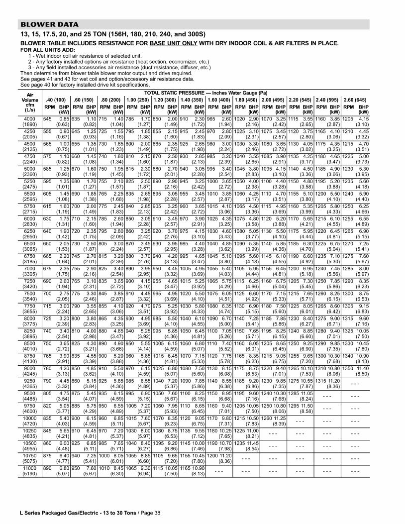
L Series Packaged Gas/Electric − 13 to 30 Tons / Page 38
BLOWER DATA
13, 15, 17.5, 20, and 25 TON (156H, 180, 210, 240, and 300S)
BLOWER TABLE INCLUDES RESISTANCE FOR BASE UNIT ONLY WITH DRY INDOOR COIL & AIR FILTERS IN PLACE.FOR ALL UNITS ADD:
1 − Wet indoor coil air resistance of selected unit.2 − Any factory installed options air resistance (heat section, economizer, etc.)3 − Any field installed accessories air resistance (duct resistance, diffuser, etc.)
Then determine from blower table blower motor output and drive required.See pages 41 and 43 for wet coil and option/accessory air resistance data.See page 40 for factory installed drive kit specifications.
Air TOTAL STATIC PRESSURE � Inches Water Gauge (Pa)AirVolume
f.40 (100) .60 (150) .80 (200) 1.00 (250) 1.20 (300) 1.40 (350) 1.60 (400) 1.80 (450) 2.00 (495) 2.20 (545) 2.40 (595) 2.60 (645)Volume
cfm(L/s)
RPM BHP(kW)
RPM BHP(kW)
RPM BHP(kW)
RPM BHP(kW)
RPM BHP(kW)
RPM BHP(kW)
RPM BHP(kW)
RPM BHP(kW)
RPM BHP(kW)
RPM BHP(kW)
RPM BHP(kW)
RPM BHP(kW)
4000(1890)
545 0.85(0.63)
635 1.10(0.82)
715 1.40(1.04)
785 1.70(1.27)
850 2.00(1.49)
910 2.30(1.72)
965 2.60(1.94)
1020 2.90(2.16)
1070 3.25(2.42)
1115 3.55(2.65)
1160 3.85(2.87)
1205 4.15(3.10)
4250(2005)
555 0.90(0.67)
645 1.25(0.93)
725 1.55(1.16)
795 1.85(1.38)
855 2.15(1.60)
915 2.45(1.83)
970 2.80(2.09)
1025 3.10(2.31)
1075 3.45(2.57)
1120 3.75(2.80)
1165 4.10(3.06)
1210 4.45(3.32)
4500(2125)
565 1.00(0.75)
655 1.35(1.01)
730 1.65(1.23)
800 2.00(1.49)
865 2.35(1.75)
925 2.65(1.98)
980 3.00(2.24)
1030 3.30(2.46)
1080 3.65(2.72)
1130 4.05(3.02)
1175 4.35(3.25)
1215 4.70(3.51)
4750(2240)
575 1.10(0.82)
660 1.45(1.08)
740 1.80(1.34)
810 2.15(1.60)
870 2.50(1.87)
930 2.85(2.13)
985 3.20(2.39)
1040 3.55(2.65)
1085 3.90(2.91)
1135 4.25(3.17)
1180 4.65(3.47)
1225 5.00(3.73)
5000(2360)
585 1.25(0.93)
670 1.60(1.19)
750 1.95(1.45)
815 2.30(1.72)
880 2.70(2.01)
940 3.05(2.28)
995 3.40(2.54)
1045 3.80(2.83)
1095 4.15(3.10)
1140 4.50(3.36)
1185 4.90(3.66)
1230 5.30(3.95)
5250(2475)
595 1.35(1.01)
680 1.70(1.27)
755 2.10(1.57)
825 2.50(1.87)
890 2.90(2.16)
945 3.25(2.42)
1000 3.65(2.72)
1050 4.00(2.98)
1100 4.40(3.28)
1150 4.80(3.58)
1195 5.20(3.88)
1235 5.60(4.18)
5500(2595)
605 1.45(1.08)
690 1.85(1.38)
765 2.25(1.68)
835 2.65(1.98)
895 3.05(2.28)
955 3.45(2.57)
1010 3.85(2.87)
1060 4.25(3.17)
1110 4.70(3.51)
1155 5.10(3.80)
1200 5.50(4.10)
1240 5.90(4.40)
5750(2715)
615 1.60(1.19)
700 2.00(1.49)
775 2.45(1.83)
840 2.85(2.13)
905 3.25(2.42)
960 3.65(2.72)
1015 4.10(3.06)
1065 4.50(3.36)
1115 4.95(3.69)
1160 5.35(3.99)
1205 5.80(4.33)
1250 6.25(4.66)
6000(2830)
630 1.75(1.31)
710 2.15(1.60)
785 2.60(1.94)
850 3.05(2.28)
910 3.45(2.57)
970 3.90(2.91)
1025 4.35(3.25)
1075 4.80(3.58)
1120 5.20(3.88)
1170 5.65(4.21)
1215 6.10(4.55)
1255 6.55(4.89)
6250(2950)
640 1.90(1.42)
720 2.35(1.75)
795 2.80(2.09)
860 3.25(2.42)
920 3.70(2.76)
975 4.15(3.10)
1030 4.60(3.43)
1080 5.05(3.77)
1130 5.50(4.10)
1175 5.95(4.44)
1220 6.45(4.81)
1265 6.90(5.15)
6500(3065)
650 2.05(1.53)
730 2.50(1.87)
805 3.00(2.24)
870 3.45(2.57)
930 3.95(2.95)
985 4.40(3.28)
1040 4.85(3.62)
1090 5.35(3.99)
1140 5.85(4.36)
1185 6.30(4.70)
1225 6.75(5.04)
1270 7.25(5.41)
6750(3185)
665 2.20(1.64)
745 2.70(2.01)
815 3.20(2.39)
880 3.70(2.76)
940 4.20(3.13)
995 4.65(3.47)
1045 5.10(3.80)
1095 5.60(4.18)
1145 6.10(4.55)
1190 6.60(4.92)
1235 7.10(5.30)
1275 7.60(5.67)
7000(3305)
675 2.35(1.75)
755 2.90(2.16)
825 3.40(2.54)
890 3.95(2.95)
950 4.45(3.32)
1005 4.95(3.69)
1055 5.40(4.03)
1105 5.95(4.44)
1155 6.45(4.81)
1200 6.95(5.18)
1240 7.45(5.56)
1285 8.00(5.97)
7250(3420)
690 2.60(1.94)
765 3.10(2.31)
835 3.65(2.72)
900 4.15(3.10)
955 4.65(3.47)
1015 5.25(3.92)
1065 5.75(4.29)
1115 6.25(4.66)
1160 6.75(5.04)
1205 7.30(5.45)
1250 7.85(5.86)
1290 8.35(6.23)
7500(3540)
700 2.75(2.05)
775 3.30(2.46)
845 3.85(2.87)
910 4.45(3.32)
965 4.95(3.69)
1020 5.50(4.10)
1075 6.05(4.51)
1125 6.60(4.92)
1170 7.15(5.33)
1215 7.65(5.71)
1260 8.25(6.15)
1300 8.75(6.53)
7750(3655)
715 3.00(2.24)
790 3.55(2.65)
855 4.10(3.06)
920 4.70(3.51)
975 5.25(3.92)
1030 5.80(4.33)
1080 6.35(4.74)
1130 6.90(5.15)
1180 7.50(5.60)
1225 8.05(6.01)
1265 8.60(6.42)
1305 9.15(6.83)
8000(3775)
725 3.20(2.39)
800 3.80(2.83)
865 4.35(3.25)
930 4.95(3.69)
985 5.50(4.10)
1040 6.10(4.55)
1090 6.70(5.00)
1140 7.25(5.41)
1185 7.85(5.86)
1230 8.40(6.27)
1275 9.00(6.71)
1315 9.60(7.16)
8250(3895)
740 3.40(2.54)
810 4.00(2.98)
880 4.65(3.47)
940 5.25(3.92)
995 5.85(4.36)
1050 6.45(4.81)
1100 7.05(5.26)
1150 7.65(5.71)
1195 8.25(6.15)
1240 8.85(6.60)
1280 9.40(7.01)
1325 10.05(7.50)
8500(4010)
750 3.65(2.72)
825 4.30(3.21)
890 4.90(3.66)
950 5.55(4.14)
1005 6.15(4.59)
1060 6.80(5.07)
1110 7.40(5.52)
1160 8.05(6.01)
1205 8.65(6.45)
1250 9.25(6.90)
1290 9.85(7.35)
1330 10.45(7.80)
8750(4130)
765 3.90(2.91)
835 4.55(3.39)
900 5.20(3.88)
960 5.85(4.36)
1015 6.45(4.81)
1070 7.15(5.33)
1120 7.75(5.78)
1165 8.35(6.23)
1215 9.05(6.75)
1255 9.65(7.20)
1300 10.30(7.68)
1340 10.90(8.13)
9000(4245)
780 4.20(3.13)
850 4.85(3.62)
910 5.50(4.10)
970 6.15(4.59)
1025 6.80(5.07)
1080 7.50(5.60)
1130 8.15(6.08)
1175 8.75(6.53)
1220 9.40(7.01)
1265 10.10(7.53)
1310 10.80(8.06)
1350 11.40(8.50)
9250(4365)
790 4.45(3.32)
860 5.15(3.84)
925 5.85(4.36)
985 6.55(4.89)
1040 7.20(5.37)
1090 7.85(5.86)
1140 8.55(6.38)
1185 9.20(6.86)
1230 9.85(7.35)
1275 10.55(7.87)
1315 11.20(8.36)
− − −
9500(4485)
805 4.75(3.54)
875 5.45(4.07)
935 6.15(4.59)
995 6.90(5.15)
1050 7.60(5.67)
1100 8.25(6.15)
1150 8.95(6.68)
1195 9.60(7.16)
1240 10.30(7.68)
1285 11.05(8.24)
− − − − − −
9750(4600)
820 5.05(3.77)
885 5.75(4.29)
950 6.55(4.89)
1005 7.20(5.37)
1060 7.95(5.93)
1110 8.65(6.45)
1160 9.40(7.01)
1205 10.05(7.50)
1250 10.80(8.06)
1295 11.50(8.58)
− − − − − −
10000(4720)
835 5.40(4.03)
900 6.15(4.59)
960 6.85(5.11)
1015 7.60(5.67)
1070 8.35(6.23)
1120 9.05(6.75)
1170 9.80(7.31)
1215 10.50(7.83)
1260 11.25(8.39)
− − − − − − − − −
10250(4835)
845 5.65(4.21)
910 6.45(4.81)
970 7.20(5.37)
1030 8.00(5.97)
1080 8.75(6.53)
1135 9.55(7.12)
1180 10.25(7.65)
1225 11.00(8.21)
− − − − − − − − − − − −
10500(4955)
860 6.00(4.48)
925 6.85(5.11)
985 7.65(5.71)
1040 8.40(6.27)
1095 9.20(6.86)
1145 10.00(7.46)
1190 10.70(7.98)
1235 11.45(8.54)
− − − − − − − − − − − −
10750(5075)
875 6.40(4.77)
940 7.25(5.41)
1000 8.05(6.01)
1055 8.85(6.60)
1105 9.65(7.20)
1155 10.45(7.80)
1200 11.20(8.36)
− − − − − − − − − − − − − − −
11000(5190)
890 6.80(5.07)
950 7.60(5.67)
1010 8.45(6.30)
1065 9.30(6.94)
1115 10.05(7.50)
1165 10.90(8.13)
− − − − − − − − − − − − − − − − − −

L Series Packaged Gas/Electric − 13 to 30 Tons / Page 39
BLOWER DATA
21, 25, and 30 TON (248H, 300H, and 360H)
BLOWER TABLE INCLUDES RESISTANCE FOR BASE UNIT ONLY WITH DRY INDOOR COIL & AIR FILTERS IN PLACE.FOR ALL UNITS ADD:
1 − Wet indoor coil air resistance of selected unit.
2 − Any factory installed options air resistance (heat section, economizer, etc.)
3 − Any field installed accessories air resistance ( duct resistance, diffuser, etc.)
Then determine from blower table blower motor output and drive required.
See pages 42−43 for wet coil and option/accessory air resistance data.
See page 40 for factory installed drive kit specifications.
BOLD INDICATES FIELD FURNISHED DRIVE
AirTOTAL STATIC PRESSURE � Inches Water Gauge (Pa)
AirVolume
f.20 (50) .40 (100) .60 (150) .80 (200) 1.00 (250) 1.20 (300) 1.40 (350) 1.60 (400) 1.80 (450) 2.00 (495) 2.20 (545) 2.40 (595) 2.60 (645)Volume
cfm(L/s)
RPM BHP
(kW)
RPM BHP
(kW)
RPM BHP
(kW)
RPM BHP
(kW)
RPM BHP
(kW)
RPM BHP
(kW)
RPM BHP
(kW)
RPM BHP
(kW)
RPM BHP
(kW)
RPM BHP
(kW)
RPM BHP
(kW)
RPM BHP
(kW)
RPM BHP
(kW)
6000
(2830)- - -
435 1.20(0.90)
525 1.45(1.08)
570 1.60(1.19)
630 2.00(1.49)
700 2.35(1.75)
750 2.80(2.09)
795 3.15(2.35)
840 3.40(2.54)
880 3.80(2.83)
920 4.20(3.13)
960 4.65(3.47)
995 5.10(3.80)
6500
(3065)- - -
445 1.30(0.97)
530 1.60(1.19)
580 1.80(1.34)
640 2.20(1.64)
705 2.60(1.94)
755 3.05(2.28)
800 3.40(2.54)
845 3.70(2.76)
885 4.15(3.10)
925 4.60(4.43)
965 5.00(3.73)
1000 5.45(4.07)
7000
(3305)- - -
455 1.40(1.04)
535 1.75(1.31)
590 2.05(1.53)
650 2.45(1.83)
710 2.85(2.13)
760 3.30(2.46)
805 3.70(2.76)
850 4.05(3.02)
890 4.50(3.36)
930 4.95(3.69)
970 5.40(4.03)
1005 5.85(4.36)
7500
(3540)380 1.05
(0.78)465 1.50
(1.12)540 1.90
(1.42)600 2.30
(1.72)660 2.70
(2.01)715 3.15
(2.35)765 3.60
(2.69)810 4.00
(2.98)855 4.45
(3.32)895 4.90
(3.66)935 5.35
(3.99)975 5.85
(4.36)1010 6.30
(4.70)
8000
(3775)390 1.25
(0.93)475 1.65
(1.23)545 2.10
(1.57)610 2.55
(1.90)665 2.95
(2.20)720 3.45
(2.57)770 3.90
(2.91)815 4.35
(3.25)860 4.85
(3.62)900 5.30
(3.95)940 5.75
(4.29)980 6.30
(4.70)1015 6.75
(5.04)
8500
(4010)405 1.40
(1.04)485 1.90
(1.42)555 2.35
(1.75)620 2.80
(2.09)675 3.30
(2.46)725 3.75
(2.80)775 4.20
(3.13)820 4.70
(3.51)865 5.20
(3.88)905 5.70
(4.25)945 6.20
(4.63)985 6.75
(5.04)1020 7.25
(5.41)
9000
(4245)415 1.60
(1.19)495 2.10
(1.57)565 2.60
(1.94)625 3.10
(2.31)685 3.60
(2.69)735 4.10
(3.06)785 4.60
(3.43)830 5.10
(3.80)870 5.60
(4.18)915 6.15
(4.59)955 6.70
(5.00)990 7.20
(5.37)1025 7.70
(5.74)
9500
(4485)430 1.85
(1.38)505 2.35
(1.75)575 2.90
(2.16)635 3.40
(2.54)690 3.90
(2.91)745 4.50
(3.36)790 4.95
(3.69)835 5.50
(4.10)880 6.05
(4.51)920 6.60
(4.92)960 7.15
(5.33)995 7.70
(5.74)1035 8.30
(6.19)
10,000
(4720)445 2.10
(1.57)520 2.65
(1.98)585 3.20
(2.39)645 3.75
(2.80)700 4.30
(3.21)750 4.85
(6.49)800 5.40
(4.03)845 5.95
(4.44)885 6.50
(4.85)925 7.05
(5.26)965 7.65
(5.71)1000 8.20
(6.12)1040 8.85
(6.60)
10,500
4955)455 2.35
(1.75)530 2.95
(2.20)595 3.50
(2.61)655 4.10
(3.06)710 4.70
(3.03)760 5.25
(3.92)805 5.80
(4.33)850 6.40
(4.77)895 7.00
(5.22)935 7.60
(5.67)970 8.15
(608)1010 8.80
(6.56)1045 9.40
(7.01)
11,000
(5190)470 2.60
(1.94)545 3.25
(2.42)605 3.85
(2.87)665 4.45
(3.32)720 5.10
(3.80)765 5.66
(4.22)815 6.30
(4.70)860 6.90
(5.15)900 7.50
(5.60)940 8.10
(6.04)980 8.75
(6.53)1015 9.35
(6.98)- - -
11,500
(5425)485 2.95
(2.20)555 3.60
(2.69)620 4.25
(3.17)675 4.85
(3.62)730 5.55
(4.14)775 6.10
(4.55)820 6.70
(5.00)865 7.40
(5.52)910 8.05
(6.01)945 8.65
(6.45)985 9.30
(6.94)1020 9.95
(7.42)- - -
12,000
(5665)500 3.30
(2.46)570 4.00
(2.98)630 4.65
(3.47)685 5.30
(3.95)740 6.00
(4.480785 6.60
(4.92)830 7.25
(5.41)875 7.95
(5.93)915 8.60
(6.42)955 9.25
(6.90)995 9.95
(7.42)1030 10.60
(7.91)- - -
12,500
(5900)515 3.65
(2.72)580 4.35
(3.25)640 5.05
(3.77)695 5.75
(4.29)750 6.50
(4.85)795 7.10
(5.30)840 7.80
(5.82)885 8.55
(6.38)925 9.20
(6.86)965 9.90
(7.39)1000 10.55
(7.87)1035 11.25
(8.39)- - -
13,000
(6135)530 4.05
(3.02)595 4.80
(3.58)655 5.55
(4.14)710 6.25
(4.66)760 7.00
(5.22)805 7.65
(5.71)850 8.40
(6.27)890 9.05
(6.75)930 9.75
(7.27)970 10.50
(7.83)101011.30
(8.43)- - - - - -
13,500
(6370)545 4.45
(3.32)610 5.25
(3.92)665 6.00
(4.48)720 6.75
(5.04)770 7.50
(5.60)815 8.25
(6.15)860 9.00
(6.71)900 9.70
(7.24)940 10.45
(7.80)980 11.20
(8.36)- - - - - - - - -
14,000
(6605)560 4.90
(3.66)620 5.70
(4.25)680 6.55
(4.89)730 7.30
(5.45)780 8.10
(6.04)825 8.85
(6.60)870 9.65
(7.20)910 10.40
7.76)950 11.15
(8.31)- - - - - - - - - - - -
14,500
(6845)575 5.40
(4.03)635 6.25
(4.66)690 7.05
(5.26)745 7.90
(5.89)790 8.65
(6.45)835 9.45
(7.05)880 10.30
(7.68)920 11.10
(8.28)- - - - - - - - - - - - - - -
15,000
(7080)590 5.90
(4.40)650 6.80
(5.07)705 7.65
(5.71)755 8.50
(6.340800 9.30
(6.94)845 10.10
(7.53)890 11.00
(8.21)- - - - - - - - - - - - - - - - - -

L Series Packaged Gas/Electric − 13 to 30 Tons / Page 40
BLOWER DATA
CONSTANT AIR VOLUME (CAV) BELT DRIVE KIT SPECIFICATIONS
Model No. Motor Efficiency Nominalhp
Maximumhp
NominalkW
MaximumkW
Drive KitNumber
RPM Range
156H Standard or High 2 hp 2.3 1.5 1.7 A 535 − 725
156H thru 210 Standard 3 hp 3.45 2.2 2.6 A1
535 − 725685 − 865
High 3 hp 3.45 2.2 2.6 2 685 − 865
156H thru 300S Standard or High 5 hp 5.75 3.7 4.3 234
685 − 865850 − 1045945 − 1185
180 thru 300S Standard or High 7.5 hp 8.63 5.6 6.4 567
945 − 11851045 − 1285850 − 1045
240 thru 300S Standard or High 10 hp 11.5 7.5 8.6 68
1045 − 12851135 − 1365
248H, 300H, and 360H Standard or High 5 hp 5.75 3.7 4.3 126
660 − 810770 − 965560 − 710
Standard or High 7.5 hp 8.63 5.6 6.4 34
715 − 880770 − 965
Standard or High 10 hp 11.5 7.5 8.6 35
715 − 880850 − 1045
NOTE − Using total air volume and system static pressure requirements determine from blower performance tables rpm and motor output required. Maximum usable outputof motors furnished are shown. In Canada, nominal motor output is also maximum usable motor output. If motors of comparable output are used, be sure to keep within theservice factor limitations outlined on the motor nameplate.
VARIABLE AIR VOLUME (VAV) DRIVE KIT SPECIFICATIONS
Model No. Motor Efficiency Nominalhp
NominalkW
Drive Kit Number Maximum RPM @ 60HzVFD Output (Fixed Pulley)
248H, 300H, and 360H Standard or High 5 hp 3.7 7 965
Standard or High 7.5 hp 5.6 8 965
Standard or High 10 hp 7.5 9 1045
NOTE − Using total air volume and system static pressure requirements determine from blower performance tables rpm and motor output required. For VFD applications,nominal motor output is also maximum usable motor output.
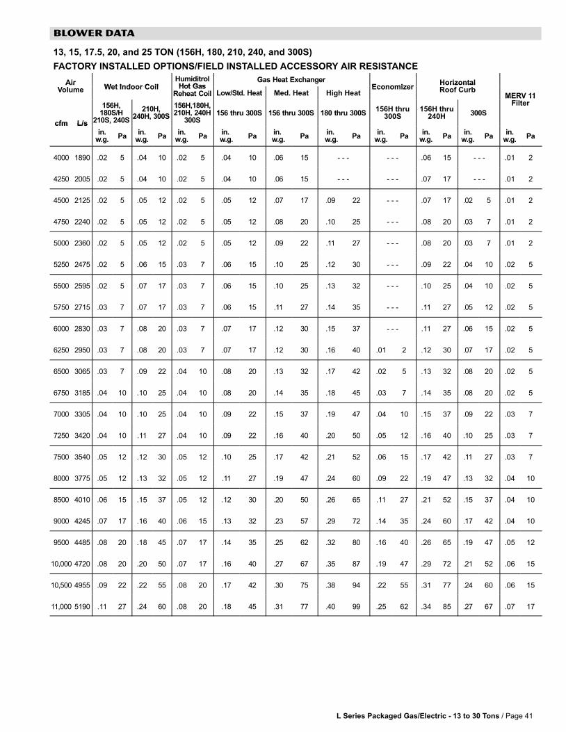
L Series Packaged Gas/Electric − 13 to 30 Tons / Page 41
BLOWER DATA
13, 15, 17.5, 20, and 25 TON (156H, 180, 210, 240, and 300S)
FACTORY INSTALLED OPTIONS/FIELD INSTALLED ACCESSORY AIR RESISTANCE
AirWet Indoor Coil
HumiditrolHot Gas
Gas Heat ExchangerEconomizer
HorizontalAirVolume Wet Indoor Coil Hot Gas
Reheat Coil Low/Std. Heat Med. Heat High HeatEconomizer
HorizontalRoof Curb
MERV 11
cfm L/s
156H,180S/H
210S, 240S
210H,240H, 300S
156H,180H,210H, 240H
300S156 thru 300S 156 thru 300S 180 thru 300S
156H thru300S
156H thru240H 300S
MERV 11Filter
cfm L/s
in.w.g. Pa
in.w.g. Pa
in.w.g. Pa
in. w.g. Pa
in. w.g. Pa
in. w.g. Pa
in.w.g. Pa
in.w.g. Pa
in.w.g. Pa
in.w.g. Pa
4000 1890 .02 5 .04 10 .02 5 .04 10 .06 15 − − − − − − .06 15 − − − .01 2
4250 2005 .02 5 .04 10 .02 5 .04 10 .06 15 − − − − − − .07 17 − − − .01 2
4500 2125 .02 5 .05 12 .02 5 .05 12 .07 17 .09 22 − − − .07 17 .02 5 .01 2
4750 2240 .02 5 .05 12 .02 5 .05 12 .08 20 .10 25 − − − .08 20 .03 7 .01 2
5000 2360 .02 5 .05 12 .02 5 .05 12 .09 22 .11 27 − − − .08 20 .03 7 .01 2
5250 2475 .02 5 .06 15 .03 7 .06 15 .10 25 .12 30 − − − .09 22 .04 10 .02 5
5500 2595 .02 5 .07 17 .03 7 .06 15 .10 25 .13 32 − − − .10 25 .04 10 .02 5
5750 2715 .03 7 .07 17 .03 7 .06 15 .11 27 .14 35 − − − .11 27 .05 12 .02 5
6000 2830 .03 7 .08 20 .03 7 .07 17 .12 30 .15 37 − − − .11 27 .06 15 .02 5
6250 2950 .03 7 .08 20 .03 7 .07 17 .12 30 .16 40 .01 2 .12 30 .07 17 .02 5
6500 3065 .03 7 .09 22 .04 10 .08 20 .13 32 .17 42 .02 5 .13 32 .08 20 .02 5
6750 3185 .04 10 .10 25 .04 10 .08 20 .14 35 .18 45 .03 7 .14 35 .08 20 .02 5
7000 3305 .04 10 .10 25 .04 10 .09 22 .15 37 .19 47 .04 10 .15 37 .09 22 .03 7
7250 3420 .04 10 .11 27 .04 10 .09 22 .16 40 .20 50 .05 12 .16 40 .10 25 .03 7
7500 3540 .05 12 .12 30 .05 12 .10 25 .17 42 .21 52 .06 15 .17 42 .11 27 .03 7
8000 3775 .05 12 .13 32 .05 12 .11 27 .19 47 .24 60 .09 22 .19 47 .13 32 .04 10
8500 4010 .06 15 .15 37 .05 12 .12 30 .20 50 .26 65 .11 27 .21 52 .15 37 .04 10
9000 4245 .07 17 .16 40 .06 15 .13 32 .23 57 .29 72 .14 35 .24 60 .17 42 .04 10
9500 4485 .08 20 .18 45 .07 17 .14 35 .25 62 .32 80 .16 40 .26 65 .19 47 .05 12
10,000 4720 .08 20 .20 50 .07 17 .16 40 .27 67 .35 87 .19 47 .29 72 .21 52 .06 15
10,500 4955 .09 22 .22 55 .08 20 .17 42 .30 75 .38 94 .22 55 .31 77 .24 60 .06 15
11,000 5190 .11 27 .24 60 .08 20 .18 45 .31 77 .40 99 .25 62 .34 85 .27 67 .07 17

L Series Packaged Gas/Electric − 13 to 30 Tons / Page 42
BLOWER DATA
21, 25, and 30 TON (248H, 300H, and 360H)
FACTORY INSTALLED OPTIONS/FIELD INSTALLED ACCESSORY AIR RESISTANCE
AirV l
Wet IndoorC il
Gas Heat ExchangerEconomizer
HorizontalR f C b
MERV 11Filt
AirVolume
Wet IndoorCoil Standard Heat Medium Heat High Heat
EconomizerHorizontalRoof Curb
MERV 11FilterVolume Coil Standard Heat Medium Heat High Heat Roof Curb Filter
cfm L/sin.
w.g. Pain.
w.g. Pain.
w.g. Pain.
w.g. Pain.
w.g. Pain.
w.g. Pain.
w.g. Pa
6000 2830 .04 10 .12 30 .16 40 .19 47 .01 3 .08 20 .01 2
6500 3070 .05 13 .13 32 .18 45 .21 52 .01 3 .09 22 .01 2
7000 3305 .06 15 .14 35 .20 50 .24 59 .02 5 .10 25 .01 2
7500 3540 .07 17 .15 37 .21 52 .25 62 .02 5 .11 27 .02 5
8000 3775 .08 20 .17 42 .24 59 .28 70 .02 5 .13 32 .02 5
8500 4010 .08 20 .20 50 .27 67 .31 77 .03 7 .15 37 .02 5
9000 4245 .09 22 .22 55 .29 72 .34 85 .04 10 .17 42 .02 5
9500 4485 .10 25 .24 60 .32 80 .38 94 .04 10 .19 47 .03 7
10,000 4720 .11 27 .27 67 .36 90 .42 104 .05 12 .21 52 .03 7
10,500 4955 .12 30 .30 75 .40 99 .46 114 .06 15 .24 60 .03 7
11,000 5190 .12 30 .33 92 .43 107 .50 137 .07 17 .27 67 .04 10
11,500 5425 .13 32 .37 92 .48 119 .55 137 .08 20 .30 75 .04 10
12,000 5665 .14 35 .40 99 .52 129 .60 149 .10 25 .33 82 .04 10
12,500 5900 .15 37 .44 109 .57 142 .65 162 .11 27 .37 92 .05 12
13,000 6135 .16 40 .48 119 .61 152 .70 174 .13 32 .40 99 .05 12
13,500 6370 .17 42 .53 132 .67 167 .76 189 .14 35 .44 109 .06 15
14,000 6605 .18 45 .57 142 .72 179 .82 204 .16 40 .49 122 .06 15
14,500 6845 .19 47 .62 154 .78 194 .89 221 .18 45 .53 132 .06 15
15,000 7080 .20 50 .68 169 .84 209 .95 236 .21 52 .58 144 .07 17

L Series Packaged Gas/Electric − 13 to 30 Tons / Page 43
BLOWER DATA
CEILING DIFFUSER AIR RESISTANCE
Step-Down Diffuser Flush Diffuser
RTD11−185 RTD11−275 LARTD30/36
Air Volume2 EndsOpen
1 Side/2EndsOpen
All Ends& SidesOpen
2 EndsOpen
1 Side/2EndsOpen
All Ends& SidesOpen
2 EndsOpen
1 Side/2EndsOpen
All Ends& SidesOpen
FD11−185 FD11−275 LAFD30/36
cfm L/sin.
w.g.Pa
in.w.g.
Pain.
w.g.Pa
in.w.g.
Pain.
w.g.Pa
in.w.g.
Pain.
w.g.Pa
in.w.g.
Pain.
w.g.Pa
in.w.g.
Pain.
w.g.Pa
in.w.g.
Pa
5000 2360 .51 127 .44 109 .39 97 − − − − − − − − − − − − − − − − − − − − − − − − − − − − − − − − − − − − .27 67 − − − − − − − − − − − −
5200 2455 .56 139 .48 119 .42 104 − − − − − − − − − − − − − − − − − − − − − − − − − − − − − − − − − − − − .30 75 − − − − − − − − − − − −
5400 2550 .61 152 .52 129 .45 112 − − − − − − − − − − − − − − − − − − − − − − − − − − − − − − − − − − − − .33 82 − − − − − − − − − − − −
5600 2645 .66 164 .56 139 .48 119 − − − − − − − − − − − − − − − − − − − − − − − − − − − − − − − − − − − − .36 90 − − − − − − − − − − − −
5800 2735 .71 177 .59 147 .51 127 − − − − − − − − − − − − − − − − − − − − − − − − − − − − − − − − − − − − .39 97 − − − − − − − − − − − −
6000 2830 .76 189 .63 157 .55 137 .36 90 .31 77 .27 67 − − − − − − − − − − − − − − − − − − .42 104 .29 72 − − − − − −
6200 2925 .80 199 .68 169 .59 147 − − − − − − − − − − − − − − − − − − − − − − − − − − − − − − − − − − − − .46 114 − − − − − − − − − − − −
6400 3020 .86 214 .72 179 .63 157 − − − − − − − − − − − − − − − − − − − − − − − − − − − − − − − − − − − − .50 124 − − − − − − − − − − − −
6500 3065 − − − − − − − − − − − − − − − − − − .42 104 .36 90 .31 77 − − − − − − − − − − − − − − − − − − − − − − − − .34 85 − − − − − −
6600 3115 .92 229 .77 191 .67 167 − − − − − − − − − − − − − − − − − − − − − − − − − − − − − − − − − − − − .54 134 − − − − − − − − − − − −
6800 3210 .99 246 .83 206 .72 174 − − − − − − − − − − − − − − − − − − − − − − − − − − − − − − − − − − − − .58 144 − − − − − − − − − − − −
7000 3305 1.03 256 .87 216 .76 189 .49 122 .41 102 .36 90 − − − − − − − − − − − − − − − − − − .62 154 .40 99 − − − − − −
7200 3400 1.09 271 .92 229 .80 199 − − − − − − − − − − − − − − − − − − − − − − − − − − − − − − − − − − − − .66 164 − − − − − − − − − − − −
7400 3490 1.15 286 .97 241 .84 209 − − − − − − − − − − − − − − − − − − − − − − − − − − − − − − − − − − − − .70 174 − − − − − − − − − − − −
7500 3540 − − − − − − − − − − − − − − − − − − .51 127 .46 114 .41 102 .37 92 .31 77 .25 62 − − − − − − .45 112 .29 72
7600 3585 1.20 301 1.02 254 .88 219 − − − − − − − − − − − − − − − − − − − − − − − − − − − − − − − − − − − − .74 184 − − − − − − − − − − − −
8000 3775 − − − − − − − − − − − − − − − − − − .59 147 .49 122 .43 107 .42 104 .36 90 .29 72 − − − − − − .50 124 .34 85
8500 4010 − − − − − − − − − − − − − − − − − − .69 172 .58 144 .50 124 .48 119 .41 102 .34 85 − − − − − − .57 142 .39 97
9000 4245 − − − − − − − − − − − − − − − − − − .79 196 .67 167 .58 144 .55 137 .47 117 .39 97 − − − − − − .66 164 .44 109
9500 4485 − − − − − − − − − − − − − − − − − − .89 221 .75 186 .65 162 .62 154 .53 132 .45 112 − − − − − − .74 184 .51 127
10,000 4720 − − − − − − − − − − − − − − − − − − 1.00 249 .84 209 .73 182 .70 174 .60 149 .51 127 − − − − − − .81 201 .57 142
10,500 4955 − − − − − − − − − − − − − − − − − − 1.10 273 .92 229 .80 199 .78 194 .68 169 .58 144 − − − − − − .89 221 .65 162
11,000 5190 − − − − − − − − − − − − − − − − − − 1.21 301 1.01 251 .88 219 .87 216 .76 190 .65 162 − − − − − − .96 239 .72 179
11,500 5425 − − − − − − − − − − − − − − − − − − − − − − − − − − − − − − − − − − − − .97 241 .85 211 .73 182 − − − − − − − − − − − − .81 201
12,000 5665 − − − − − − − − − − − − − − − − − − − − − − − − − − − − − − − − − − − − 1.08 269 .94 234 .82 204 − − − − − − − − − − − − .90 223
12,500 5900 − − − − − − − − − − − − − − − − − − − − − − − − − − − − − − − − − − − − 1.19 296 1.04 259 .91 226 − − − − − − − − − − − − .99 246
13,000 6135 − − − − − − − − − − − − − − − − − − − − − − − − − − − − − − − − − − − − 1.30 323 1.15 286 1.00 249 − − − − − − − − − − − − 1.10 274
13,500 6370 − − − − − − − − − − − − − − − − − − − − − − − − − − − − − − − − − − − − 1.43 356 1.26 313 1.10 374 − − − − − − − − − − − − 1.20 298
14,000 6605 − − − − − − − − − − − − − − − − − − − − − − − − − − − − − − − − − − − − 1.56 388 1.38 343 1.20 298 − − − − − − − − − − − − 1.31 326
14,500 6845 − − − − − − − − − − − − − − − − − − − − − − − − − − − − − − − − − − − − 1.69 420 1.50 373 1.31 326 − − − − − − − − − − − − 1.43 356
15,000 7080 − − − − − − − − − − − − − − − − − − − − − − − − − − − − − − − − − − − − 1.84 457 1.63 405 1.43 356 − − − − − − − − − − − − 1.56 388

L Series Packaged Gas/Electric − 13 to 30 Tons / Page 44
BLOWER DATA
POWER EXHAUST FANS50% HIGH STATIC OPERATION
BOLD INDICATES FIELD FURNISHED DRIVE
AirReturn Duct Negative Static Pressure − Inches Water Gauge (Pa)
AirVolume
f0 (0) .10 (25) .20 (50) .30 (75) .40 (100) .50 (125) .60 (150) .70 (175) .80 (200) .90 (225) 1.0 (250)Volume
cfm(L/s) RPM BHP
(kW)RPM BHP
(kW)RPM BHP
(kW)RPM BHP
(kW)RPM BHP
(kW)RPM BHP
(kW)RPM BHP
(kW)RPM BHP
(kW)RPM BHP
(kW)RPM BHP
(kW)RPM BHP
(kW)
4000(1890)
335 0.30(0.22)
380 0.35(0.26)
430 0.40(0.30)
475 0.45(0.34)
520 0.50(0.37)
570 0.55(0.41)
615 0.65(0.48)
665 0.70(0.52)
710 0.75(0.56)
755 0.85(0.63)
− − −
4500(2125)
375 0.40(0.30)
415 0.45(0.34)
460 0.55(0.41)
500 0.60(0.45)
545 0.65(0.48)
585 0.70(0.52)
625 0.80(0.60)
670 0.85(0.63)
710 0.95(0.71)
750 1.00(0.75)
795 1.10(0.82)
5000(2360)
415 0.55(0.41)
455 0.65(0.48)
490 0.70(0.52)
530 0.75(0.56)
570 0.85(0.63)
605 0.90(0.67)
645 1.00(0.75)
680 1.05(0.78)
720 1.15(0.86)
755 1.20(0.90)
795 1.30(0.97)
5500(2595)
460 0.75(0.56)
495 0.85(0.63)
525 0.90(0.67)
560 0.95(0.71)
595 1.05(0.78)
630 1.10(0.82)
665 1.20(0.90)
700 1.30(0.97)
735 1.35(1.01)
765 1.45(1.08)
800 1.55(1.16)
6000(2830)
500 1.00(0.75)
530 1.05(0.78)
565 1.15(0.86)
595 1.20(0.90)
625 1.30(0.97)
660 1.40(1.04)
690 1.45(1.08)
720 1.55(1.16)
750 1.65(1.23)
785 1.70(1.27)
815 1.80(1.34)
6500(3065)
540 1.25(0.93)
570 1.30(0.97)
600 1.40(1.04)
630 1.50(1.12)
660 1.60(1.19)
685 1.65(1.23)
715 1.75(1.31)
745 1.85(1.38)
775 1.95(1.45)
805 2.05(1.53)
830 2.10(1.57)
7000(3305)
585 1.55(1.16)
610 1.65(1.23)
635 1.70(1.27)
665 1.85(1.38)
690 1.90(1.42)
720 2.00(1.49)
745 2.10(1.57)
770 2.20(1.64)
800 2.30(1.72)
825 2.40(1.79)
855 2.50(1.87)
7500(3540)
625 1.90(1.42)
650 2.00(1.49)
675 2.10(1.57)
700 2.20(1.64)
725 2.30(1.72)
750 2.40(1.79)
775 2.50(1.87)
800 2.60(1.94)
825 2.70(2.01)
850 2.80(2.09)
875 2.90(2.16)
8000(3775)
665 2.30(1.72)
690 2.40(1.79)
715 2.55(1.90)
735 2.60(1.94)
760 2.70(2.01)
785 2.85(2.13)
810 2.95(2.20)
830 3.05(2.28)
855 3.15(2.35)
880 3.25(2.42)
905 3.40(2.54)
8500(4010)
710 2.80(2.09)
730 2.90(2.16)
755 3.00(2.24)
775 3.10(2.31)
795 3.20(2.39)
820 3.35(2.50)
840 3.45(2.57)
865 3.55(2.65)
885 3.65(2.72)
910 3.80(2.83)
930 3.90(2.91)
POWER EXHAUST FANS100% HIGH STATIC OPERATION
BOLD INDICATES FIELD FURNISHED DRIVE
AirReturn Duct Negative Static Pressure − Inches Water Gauge (Pa)
AirVolume
f0 (0) .10 (25) .20 (50) .30 (75) .40 (100) .50 (125) .60 (150) .70 (175) .80 (200) .90 (225) 1.0 (250)Volume
cfm(L/s) RPM BHP
(kW)RPM BHP
(kW)RPM BHP
(kW)RPM BHP
(kW)RPM BHP
(kW)RPM BHP
(kW)RPM BHP
(kW)RPM BHP
(kW)RPM BHP
(kW)RPM BHP
(kW)RPM BHP
(kW)
8500(4010)
475 1.30(0.97)
500 1.30(0.97)
525 1.40(1.04)
550 1.50(1.12)
585 1.60(1.19)
625 1.75(1.31)
670 1.90(1.42)
710 2.10(1.57)
745 2.30(1.72)
780 2.50(1.87)
815 2.70(2.01)
9000(4245)
520 1.55(1.16)
535 1.60(1.19)
550 1.65(1.23)
570 1.70(1.27)
605 1.85(1.38)
640 1.95(1.45)
685 2.15(1.60)
720 2.35(1.75)
760 2.55(1.90)
790 2.75(2.05)
825 3.00(2.24)
9500(4485)
550 1.80(1.34)
560 1.85(1.38)
575 1.90(1.42)
600 2.00(1.49)
620 2.10(1.57)
655 2.20(1.64)
695 2.40(1.79)
735 2.60(1.94)
770 2.80(2.09)
800 3.00(2.24)
835 3.25(2.42)
10,000(4720)
575 2.10(1.57)
590 2.15(1.60)
605 2.20(1.64)
620 2.30(1.72)
645 2.40(1.79)
675 2.50(1.87)
710 2.65(1.98)
745 2.85(2.13)
780 3.05(2.28)
815 3.30(2.46)
845 3.50(2.61)
10,500(4955)
605 2.45(1.83)
615 2.45(1.83)
625 2.50(1.87)
645 2.60(1.94)
670 2.75(2.05)
690 2.80(2.09)
725 3.00(2.24)
755 3.15(2.35)
790 3.35(2.50)
825 3.60(2.69)
855 3.80(2.83)
11,000(5190)
630 2.80(2.09)
645 2.85(2.13)
660 2.95(2.20)
675 3.00(2.24)
685 3.05(2.28)
715 3.20(2.39)
740 3.30(2.46)
770 3.50(2.61)
805 3.70(2.76)
835 3.90(2.91)
870 4.20(3.13)
11,500(5425)
665 3.25(2.42)
675 3.30(2.46)
680 3.30(2.46)
695 3.40(2.54)
715 3.50(2.61)
735 3.60(2.69)
755 3.70(2.76)
785 3.85(2.87)
815 4.05(3.02)
850 4.30(3.21)
880 4.50(3.36)
12,000(5665)
685 3.60(2.69)
700 3.70(2.76)
710 3.75(2.80)
725 3.85(2.87)
740 3.95(2.95)
755 4.00(2.98)
780 4.15(3.10)
805 4.30(3.21)
830 4.45(3.32)
860 4.65(3.47)
890 4.90(3.66)
12,500(5900)
720 4.10(3.06)
730 4.20(3.13)
740 4.25(3.17)
750 4.30(3.21)
765 4.40(3.28)
780 4.50(3.36)
800 4.60(3.43)
820 4.75(3.54)
845 4.90(3.66)
875 5.10(3.80)
905 5.35(3.99)
13,000(6135)
745 4.60(3.43)
750 4.65(3.47)
765 4.75(3.54)
780 4.85(3.62)
790 4.90(3.66)
805 5.00(3.73)
820 5.10(3.80)
840 5.25(3.92)
865 5.40(4.03)
890 5.60(4.18)
915 5.80(4.33)
13,500(6370)
775 5.15(3.84)
785 5.25(3.92)
795 5.35(3.99)
805 5.40(4.03)
815 5.50(4.10)
830 5.60(4.18)
845 5.70(4.25)
865 5.80(4.33)
880 5.95(4.44)
905 6.10(4.55)
930 6.30(4.70)
14,000(6605)
805 5.80(4.33)
810 5.80(4.33)
820 5.90(4.40)
830 6.00(4.48)
845 6.10(4.55)
855 6.20(4.63)
870 6.30(4.70)
885 6.40(4.77)
905 6.55(4.89)
925 6.70(5.00)
945 6.85(5.11)
HIGH STATIC POWER EXHAUST FANS WITH CONSTANT AIR VOLUME − DRIVE KIT SPECIFICATIONS
Unit Model No. Power Exhaust FanModel No.
Motor HP Drive Kit Number RPM Range
248H, 300H, and 360H LAPEB30/36A (50%) (2) 2 hp 1 406 − 533, ,
LAPEB30/36B (50%) (2) 2 hp 2 531 − 731
LAPEB30/36C (50%) (2) 2 hp 3 731 − 932
LAPEB30/36D (100%) (3) 2 hp 1 406 − 533
LAPEB30/36E (100%) (3) 2 hp 2 531 − 731
LAPEB30/36F (100%) (3) 2 hp 3 731 − 932
NOTE − Using total air volume and system static pressure requirements, determine from blower performance tables rpm and required.
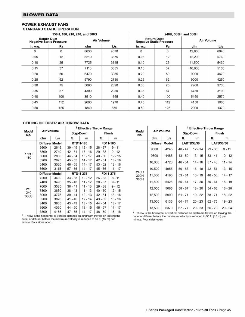
L Series Packaged Gas/Electric − 13 to 30 Tons / Page 45
BLOWER DATA
POWER EXHAUST FANSSTANDARD STATIC OPERATION
156H, 180, 210, 240, and 300S 248H, 300H, and 360H
Return DuctNegative Static Pressure Air Volume
Return DuctNegative Static Pressure Air Volume
in. w.g. Pa cfm L/s in. w.g. Pa cfm L/s
0 0 8630 4070 0 0 12,800 6040
0.05 12 8210 3875 0.05 12 12,200 5760
0.10 25 7725 3645 0.10 25 11,500 5430
0.15 37 7110 3355 0.15 37 10,800 5100
0.20 50 6470 3055 0.20 50 9900 4670
0.25 62 5790 2730 0.25 62 9000 4250
0.30 75 5060 2390 0.30 75 7900 3730
0.35 87 4300 2030 0.35 87 6750 3190
0.40 100 3510 1655 0.40 100 5450 2570
0.45 112 2690 1270 0.45 112 4150 1960
0.50 125 1840 870 0.50 125 2900 1370
CEILING DIFFUSER AIR THROW DATA
Model Air Volume1 Effective Throw Range
ModelNo.
Air VolumeStep-Down Flush
No.cfm L/s ft. m ft. m
Diffuser Model RTD11−185 FD11−185
5600 2645 39 − 49 12 − 15 28 − 37 9 − 11
156H5800 2740 42 − 51 13 − 16 29 − 38 9 − 12
156H180
6000 2830 44 − 54 13 − 17 40 − 50 12 − 15180
6200 2925 45 − 55 14 − 17 42 − 51 13 − 16
6400 3020 46 − 55 14 − 17 53 − 52 13 − 16
6600 3115 57 − 56 14 − 17 45 − 56 14 − 17
Diffuser Model RTD11−275 FD11−275
7200 3400 33 − 38 10 − 12 26 − 35 8 − 11
7400 3490 35 − 40 11 − 12 28 − 37 9 − 11
2107600 3585 36 − 41 11 − 13 29 − 38 9 − 12
210240
7800 3680 38 − 43 11 − 13 40 − 50 12 − 15240
300S 8000 3775 39 − 44 12 − 13 42 − 51 13 − 16300S8200 3870 41 − 46 12 − 14 43 − 52 13 − 16
8400 3965 43 − 49 13 − 15 44 − 54 13 − 17
8600 4060 44 − 50 13 − 15 46 − 57 14 − 17
8800 4155 47 − 55 14 − 17 48 − 59 15 − 181 Throw is the horizontal or vertical distance an airstream travels on leaving theoutlet�or diffuser before the maximum velocity is reduced to 50 ft. (15 m) perminute. Four sides open.
Model Air Volume1 Effective Throw Range
ModelNo.
Air VolumeStep-Down Flush
No.cfm L/s ft. m ft. m
Diffuser Model LARTD30/36 LAFD30/36
9000 4245 40 − 47 12 − 14 29 − 35 8 − 11
9500 4485 43 − 50 13 − 15 33 − 41 10 − 12
10,000 4720 46 − 54 14 − 16 37 − 46 11 − 14
248H10,500 4955 50 − 58 15 − 18 42 − 51 13 − 15
248H300H360H
11,000 4190 53 − 61 16 − 19 46 − 56 14 − 17
360H11,500 5425 55 − 64 17 − 20 50 − 61 15 − 19
12,000 5665 58 − 67 18 − 20 54 − 66 16 − 20
12,500 5900 61 − 71 19 − 22 58 − 71 18 − 22
13,000 6135 64 − 74 20 − 23 62 − 75 19 − 23
13,500 6370 67 − 77 20 − 23 66 − 79 20 − 24
1 Throw is the horizontal or vertical distance an airstream travels on leaving theoutlet�or diffuser before the maximum velocity is reduced to 50 ft. (15 m) perminute. Four sides open.

L Series Packaged Gas/Electric − 13 to 30 Tons / Page 46
OPTIONAL DISCONNECT SWITCH REQUIREMENTS
Model No Voltage Blower Motor hpDisconnect Switch
Model No. Voltage Blower Motor hp80A 150A 250A
208/230v−3ph 2, 3 30M39 − − − − − −
156H208/230v−3ph 5 − − − 30M40 − − −
156H460v−3ph 2, 3, 5 30M39 − − − − − −
575v−3ph 2, 3, 5 30M39 − − − − − −
180208/230v−3ph 3, 5, 7.5 − − − 30M40 − − −
180210
460v−3ph 3, 5, 7.5 30M39 − − − − − −210
575v−3ph 3, 5, 7.5 30M39 − − − − − −
240 208/230v−3ph 5, 7.5, 10 − − − 30M40 − − −240248300
460v−3ph 5, 7.5, 10 30M39 − − − − − −248300 575v−3ph 5, 7.5, 10 30M39 − − − − − −
208/230v−3ph 5, 7.5, 10 − − − − − − 30M41
360 460v−3ph 5, 7.5, 10 30M39 − − − − − −360
575v−3ph 5, 7.5, 10 30M39 − − − − − −
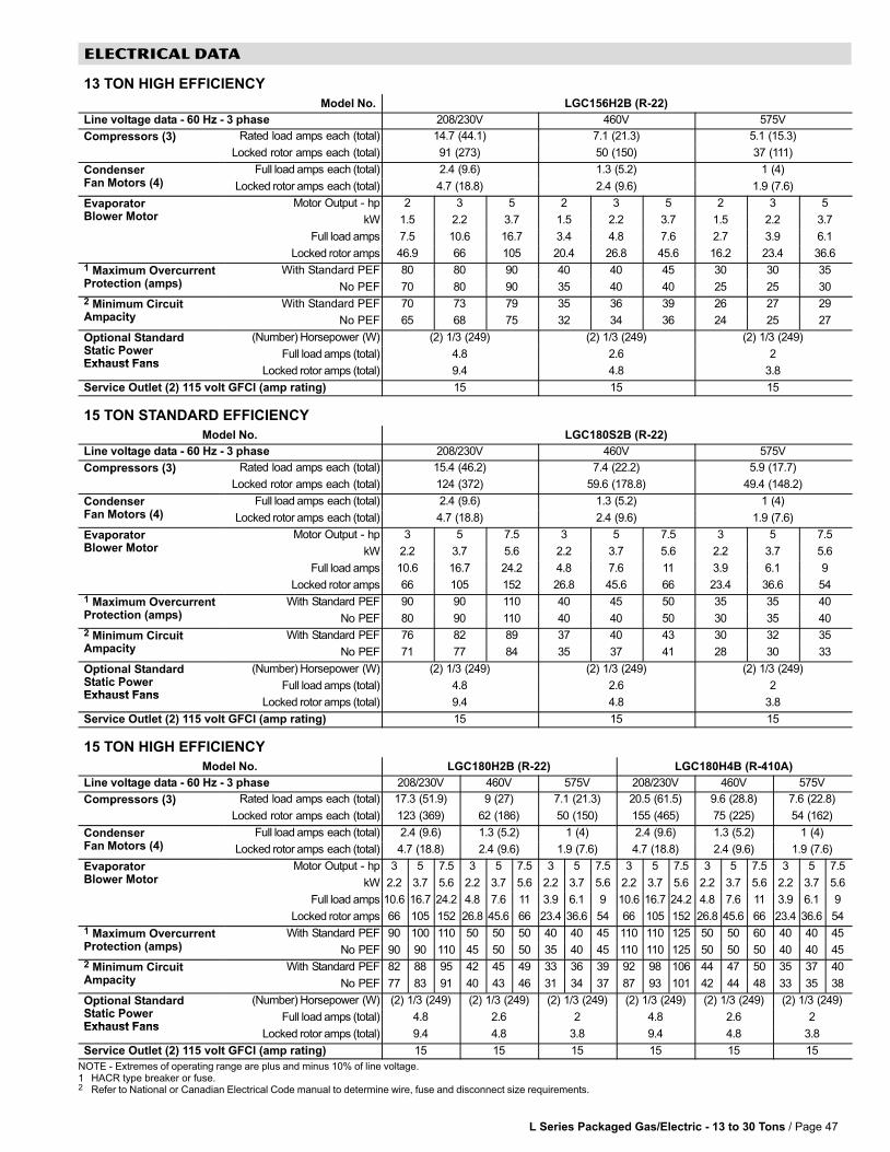
L Series Packaged Gas/Electric − 13 to 30 Tons / Page 47
ELECTRICAL DATA
13 TON HIGH EFFICIENCY
Model�No. LGC156H2B (R−22)
Line�voltage�data�−�60�Hz�−�3�phase 208/230V 460V 575V
Compressors (3) Rated load amps each (total) 14.7 (44.1) 7.1 (21.3) 5.1 (15.3)p ( )
Locked rotor amps each (total) 91 (273) 50 (150) 37 (111)
CondenserF M t (4)
Full�load�amps each�(total) 2.4 (9.6) 1.3 (5.2) 1 (4)Fan�Motors (4) Locked�rotor�amps each�(total) 4.7 (18.8) 2.4 (9.6) 1.9 (7.6)
EvaporatorBl M t
Motor Output − hp 2 3 5 2 3 5 2 3 5pBlower Motor kW 1.5 2.2 3.7 1.5 2.2 3.7 1.5 2.2 3.7
Full�load�amps 7.5 10.6 16.7 3.4 4.8 7.6 2.7 3.9 6.1
Locked�rotor�amps 46.9 66 105 20.4 26.8 45.6 16.2 23.4 36.6
1 Maximum OvercurrentP t ti ( )
With Standard PEF 80 80 90 40 40 45 30 30 35Protection (amps) No PEF 70 80 90 35 40 40 25 25 30
2 Minimum CircuitA it
With Standard PEF 70 73 79 35 36 39 26 27 29Ampacity No PEF 65 68 75 32 34 36 24 25 27
Optional StandardSt ti P
(Number)�Horsepower (W) (2) 1/3 (249) (2) 1/3 (249) (2) 1/3 (249)pStatic PowerExhaust Fans
Full�load�amps�(total) 4.8 2.6 2Exhaust Fans
Locked�rotor�amps�(total) 9.4 4.8 3.8
Service Outlet (2) 115 volt GFCI (amp rating) 15 15 15
15 TON STANDARD EFFICIENCY
Model�No. LGC180S2B (R−22)
Line�voltage�data�−�60�Hz�−�3�phase 208/230V 460V 575V
Compressors (3) Rated load amps each (total) 15.4 (46.2) 7.4 (22.2) 5.9 (17.7)p ( )
Locked rotor amps each (total) 124 (372) 59.6 (178.8) 49.4 (148.2)
CondenserF M t (4)
Full�load�amps each�(total) 2.4 (9.6) 1.3 (5.2) 1 (4)Fan�Motors (4) Locked�rotor�amps each�(total) 4.7 (18.8) 2.4 (9.6) 1.9 (7.6)
EvaporatorBl M t
Motor Output − hp 3 5 7.5 3 5 7.5 3 5 7.5pBlower Motor kW 2.2 3.7 5.6 2.2 3.7 5.6 2.2 3.7 5.6
Full�load�amps 10.6 16.7 24.2 4.8 7.6 11 3.9 6.1 9
Locked�rotor�amps 66 105 152 26.8 45.6 66 23.4 36.6 54
1 Maximum OvercurrentP t ti ( )
With Standard PEF 90 90 110 40 45 50 35 35 40Protection (amps) No PEF 80 90 110 40 40 50 30 35 40
2 Minimum CircuitA it
With Standard PEF 76 82 89 37 40 43 30 32 35Ampacity No PEF 71 77 84 35 37 41 28 30 33
Optional StandardSt ti P
(Number)�Horsepower (W) (2) 1/3 (249) (2) 1/3 (249) (2) 1/3 (249)pStatic PowerExhaust Fans
Full�load�amps�(total) 4.8 2.6 2Exhaust Fans
Locked�rotor�amps�(total) 9.4 4.8 3.8
Service Outlet (2) 115 volt GFCI (amp rating) 15 15 15
15 TON HIGH EFFICIENCY
Model�No. LGC180H2B (R−22) LGC180H4B (R−410A)
Line�voltage�data�−�60�Hz�−�3�phase 208/230V 460V 575V 208/230V 460V 575V
Compressors (3) Rated load amps each (total) 17.3 (51.9) 9 (27) 7.1 (21.3) 20.5 (61.5) 9.6 (28.8) 7.6 (22.8)p ( )
Locked rotor amps each (total) 123 (369) 62 (186) 50 (150) 155 (465) 75 (225) 54 (162)
CondenserF M t (4)
Full�load�amps each�(total) 2.4 (9.6) 1.3 (5.2) 1 (4) 2.4 (9.6) 1.3 (5.2) 1 (4)Fan�Motors (4) Locked�rotor�amps each�(total) 4.7 (18.8) 2.4 (9.6) 1.9 (7.6) 4.7 (18.8) 2.4 (9.6) 1.9 (7.6)
EvaporatorBl M t
Motor Output − hp 3 5 7.5 3 5 7.5 3 5 7.5 3 5 7.5 3 5 7.5 3 5 7.5pBlower Motor kW 2.2 3.7 5.6 2.2 3.7 5.6 2.2 3.7 5.6 2.2 3.7 5.6 2.2 3.7 5.6 2.2 3.7 5.6
Full�load�amps 10.6 16.7 24.2 4.8 7.6 11 3.9 6.1 9 10.6 16.7 24.2 4.8 7.6 11 3.9 6.1 9
Locked�rotor�amps 66 105 152 26.8 45.6 66 23.4 36.6 54 66 105 152 26.8 45.6 66 23.4 36.6 54
1 Maximum OvercurrentP t ti ( )
With Standard PEF 90 100 110 50 50 50 40 40 45 110 110 125 50 50 60 40 40 45Protection (amps) No PEF 90 90 110 45 50 50 35 40 45 110 110 125 50 50 50 40 40 45
2 Minimum CircuitA it
With Standard PEF 82 88 95 42 45 49 33 36 39 92 98 106 44 47 50 35 37 40Ampacity No PEF 77 83 91 40 43 46 31 34 37 87 93 101 42 44 48 33 35 38
Optional StandardSt ti P
(Number)�Horsepower (W) (2) 1/3 (249) (2) 1/3 (249) (2) 1/3 (249) (2) 1/3 (249) (2) 1/3 (249) (2) 1/3 (249)pStatic PowerExhaust Fans
Full�load�amps�(total) 4.8 2.6 2 4.8 2.6 2Exhaust Fans
Locked�rotor�amps�(total) 9.4 4.8 3.8 9.4 4.8 3.8
Service Outlet (2) 115 volt GFCI (amp rating) 15 15 15 15 15 15
NOTE�− Extremes�of�operating�range�are�plus�and�minus�10%�of�line�voltage.1 HACR type breaker or fuse.2 Refer�to�National or Canadian�Electrical�Code�manual�to�determine�wire,�fuse�and�disconnect�size�requirements.
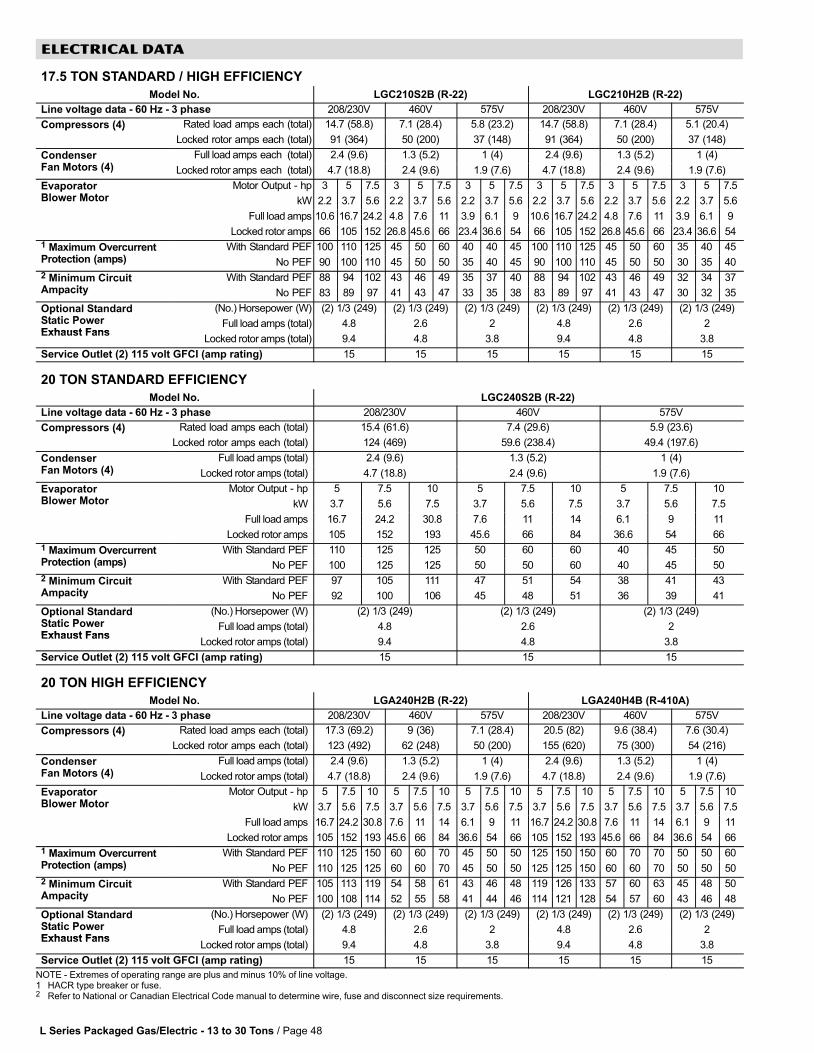
L Series Packaged Gas/Electric − 13 to 30 Tons / Page 48
ELECTRICAL DATA
17.5 TON STANDARD / HIGH EFFICIENCY
Model�No. LGC210S2B (R−22) LGC210H2B (R−22)
Line�voltage�data�−�60�Hz�−�3�phase 208/230V 460V 575V 208/230V 460V 575V
Compressors (4) Rated load amps each (total) 14.7 (58.8) 7.1 (28.4) 5.8 (23.2) 14.7 (58.8) 7.1 (28.4) 5.1 (20.4)p ( )
Locked rotor amps each (total) 91 (364) 50 (200) 37 (148) 91 (364) 50 (200) 37 (148)
CondenserF M t (4)
Full�load�amps each �(total) 2.4 (9.6) 1.3 (5.2) 1 (4) 2.4 (9.6) 1.3 (5.2) 1 (4)Fan�Motors (4) Locked�rotor�amps each �(total) 4.7 (18.8) 2.4 (9.6) 1.9 (7.6) 4.7 (18.8) 2.4 (9.6) 1.9 (7.6)
EvaporatorBl M t
Motor Output − hp 3 5 7.5 3 5 7.5 3 5 7.5 3 5 7.5 3 5 7.5 3 5 7.5pBlower Motor kW 2.2 3.7 5.6 2.2 3.7 5.6 2.2 3.7 5.6 2.2 3.7 5.6 2.2 3.7 5.6 2.2 3.7 5.6
Full�load�amps 10.6 16.7 24.2 4.8 7.6 11 3.9 6.1 9 10.6 16.7 24.2 4.8 7.6 11 3.9 6.1 9
Locked�rotor�amps 66 105 152 26.8 45.6 66 23.4 36.6 54 66 105 152 26.8 45.6 66 23.4 36.6 54
1 Maximum OvercurrentP t ti ( )
With Standard PEF 100 110 125 45 50 60 40 40 45 100 110 125 45 50 60 35 40 45Protection (amps) No PEF 90 100 110 45 50 50 35 40 45 90 100 110 45 50 50 30 35 40
2 Minimum CircuitA it
With Standard PEF 88 94 102 43 46 49 35 37 40 88 94 102 43 46 49 32 34 37Ampacity No PEF 83 89 97 41 43 47 33 35 38 83 89 97 41 43 47 30 32 35
Optional StandardSt ti P
(No.)�Horsepower (W) (2) 1/3 (249) (2) 1/3 (249) (2) 1/3 (249) (2) 1/3 (249) (2) 1/3 (249) (2) 1/3 (249)pStatic PowerExhaust Fans
Full�load�amps�(total) 4.8 2.6 2 4.8 2.6 2Exhaust Fans
Locked�rotor�amps�(total) 9.4 4.8 3.8 9.4 4.8 3.8
Service Outlet (2) 115 volt GFCI (amp rating) 15 15 15 15 15 15
20 TON STANDARD EFFICIENCY
Model�No. LGC240S2B (R−22)
Line�voltage�data�−�60�Hz�−�3�phase 208/230V 460V 575V
Compressors (4) Rated load amps each (total) 15.4 (61.6) 7.4 (29.6) 5.9 (23.6)p ( )
Locked rotor amps each (total) 124 (469) 59.6 (238.4) 49.4 (197.6)
CondenserF M t (4)
Full�load�amps�(total) 2.4 (9.6) 1.3 (5.2) 1 (4)Fan�Motors (4) Locked�rotor�amps�(total) 4.7 (18.8) 2.4 (9.6) 1.9 (7.6)
EvaporatorBl M t
Motor Output − hp 5 7.5 10 5 7.5 10 5 7.5 10pBlower Motor kW 3.7 5.6 7.5 3.7 5.6 7.5 3.7 5.6 7.5
Full�load�amps 16.7 24.2 30.8 7.6 11 14 6.1 9 11
Locked�rotor�amps 105 152 193 45.6 66 84 36.6 54 66
1 Maximum OvercurrentP t ti ( )
With Standard PEF 110 125 125 50 60 60 40 45 50Protection (amps) No PEF 100 125 125 50 50 60 40 45 50
2 Minimum CircuitA it
With Standard PEF 97 105 111 47 51 54 38 41 43Ampacity No PEF 92 100 106 45 48 51 36 39 41
Optional StandardSt ti P
(No.)�Horsepower (W) (2) 1/3 (249) (2) 1/3 (249) (2) 1/3 (249)pStatic PowerExhaust Fans
Full�load�amps�(total) 4.8 2.6 2Exhaust Fans
Locked�rotor�amps�(total) 9.4 4.8 3.8
Service Outlet (2) 115 volt GFCI (amp rating) 15 15 15
20 TON HIGH EFFICIENCY
Model�No. LGA240H2B (R−22) LGA240H4B (R−410A)
Line�voltage�data�−�60�Hz�−�3�phase 208/230V 460V 575V 208/230V 460V 575V
Compressors (4) Rated load amps each (total) 17.3 (69.2) 9 (36) 7.1 (28.4) 20.5 (82) 9.6 (38.4) 7.6 (30.4)p ( )
Locked rotor amps each (total) 123 (492) 62 (248) 50 (200) 155 (620) 75 (300) 54 (216)
CondenserF M t (4)
Full�load�amps�(total) 2.4 (9.6) 1.3 (5.2) 1 (4) 2.4 (9.6) 1.3 (5.2) 1 (4)Fan�Motors (4) Locked�rotor�amps�(total) 4.7 (18.8) 2.4 (9.6) 1.9 (7.6) 4.7 (18.8) 2.4 (9.6) 1.9 (7.6)
EvaporatorBl M t
Motor Output − hp 5 7.5 10 5 7.5 10 5 7.5 10 5 7.5 10 5 7.5 10 5 7.5 10pBlower Motor kW 3.7 5.6 7.5 3.7 5.6 7.5 3.7 5.6 7.5 3.7 5.6 7.5 3.7 5.6 7.5 3.7 5.6 7.5
Full�load�amps 16.7 24.2 30.8 7.6 11 14 6.1 9 11 16.7 24.2 30.8 7.6 11 14 6.1 9 11
Locked�rotor�amps 105 152 193 45.6 66 84 36.6 54 66 105 152 193 45.6 66 84 36.6 54 66
1 Maximum OvercurrentP t ti ( )
With Standard PEF 110 125 150 60 60 70 45 50 50 125 150 150 60 70 70 50 50 60Protection (amps) No PEF 110 125 125 60 60 70 45 50 50 125 125 150 60 60 70 50 50 50
2 Minimum CircuitA it
With Standard PEF 105 113 119 54 58 61 43 46 48 119 126 133 57 60 63 45 48 50Ampacity No PEF 100 108 114 52 55 58 41 44 46 114 121 128 54 57 60 43 46 48
Optional StandardSt ti P
(No.)�Horsepower (W) (2) 1/3 (249) (2) 1/3 (249) (2) 1/3 (249) (2) 1/3 (249) (2) 1/3 (249) (2) 1/3 (249)pStatic PowerExhaust Fans
Full�load�amps�(total) 4.8 2.6 2 4.8 2.6 2Exhaust Fans
Locked�rotor�amps�(total) 9.4 4.8 3.8 9.4 4.8 3.8
Service Outlet (2) 115 volt GFCI (amp rating) 15 15 15 15 15 15
NOTE�− Extremes�of�operating�range�are�plus�and�minus�10%�of�line�voltage.1 HACR type breaker or fuse.2 Refer�to�National or Canadian�Electrical�Code�manual�to�determine�wire,�fuse�and�disconnect�size�requirements.
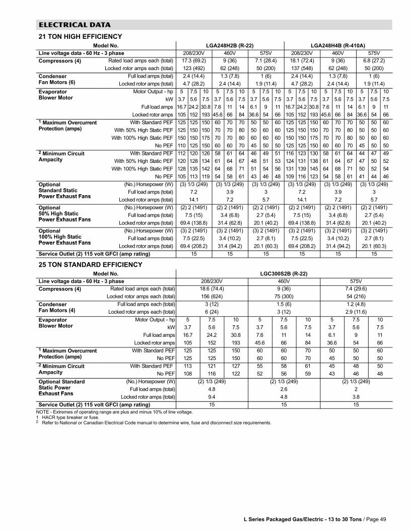
L Series Packaged Gas/Electric − 13 to 30 Tons / Page 49
ELECTRICAL DATA
21 TON HIGH EFFICIENCY
Model�No. LGA248H2B (R−22) LGA248H4B (R−410A)
Line�voltage�data�−�60�Hz�−�3�phase 208/230V 460V 575V 208/230V 460V 575V
Compressors (4) Rated load amps each (total) 17.3 (69.2) 9 (36) 7.1 (28.4) 18.1 (72.4) 9 (36) 6.8 (27.2)p ( )
Locked rotor amps each (total) 123 (492) 62 (248) 50 (200) 137 (548) 62 (248) 50 (200)
CondenserF M t (6)
Full�load�amps�(total) 2.4 (14.4) 1.3 (7.8) 1 (6) 2.4 (14.4) 1.3 (7.8) 1 (6)Fan�Motors (6) Locked�rotor�amps�(total) 4.7 (28.2) 2.4 (14.4) 1.9 (11.4) 4.7 (28.2) 2.4 (14.4) 1.9 (11.4)
EvaporatorBl M t
Motor Output − hp 5 7.5 10 5 7.5 10 5 7.5 10 5 7.5 10 5 7.5 10 5 7.5 10pBlower Motor kW 3.7 5.6 7.5 3.7 5.6 7.5 3.7 5.6 7.5 3.7 5.6 7.5 3.7 5.6 7.5 3.7 5.6 7.5
Full�load�amps 16.7 24.2 30.8 7.6 11 14 6.1 9 11 16.7 24.2 30.8 7.6 11 14 6.1 9 11
Locked�rotor�amps 105 152 193 45.6 66 84 36.6 54 66 105 152 193 45.6 66 84 36.6 54 66
1 Maximum OvercurrentP t ti ( )
With Standard PEF 125 125 150 60 70 70 50 50 60 125 125 150 60 70 70 50 50 60Protection (amps) With 50% High Static PEF 125 150 150 70 70 80 50 60 60 125 150 150 70 70 80 50 50 60
With 100% High Static PEF 150 150 175 70 70 80 60 60 60 150 150 175 70 70 80 50 60 60
No PEF 110 125 150 60 60 70 45 50 50 125 125 150 60 60 70 45 50 50
2 Minimum CircuitA it
With Standard PEF 112 120 126 58 61 64 46 49 51 116 123 130 58 61 64 44 47 49Ampacity With 50% High Static PEF 120 128 134 61 64 67 48 51 53 124 131 138 61 64 67 47 50 52
With 100% High Static PEF 128 135 142 64 68 71 51 54 56 131 139 145 64 68 71 50 52 54
No PEF 105 113 119 54 58 61 43 46 48 109 116 123 54 58 61 41 44 46
OptionalSt d d St ti
(No.)�Horsepower (W) (3) 1/3 (249) (3) 1/3 (249) (3) 1/3 (249) (3) 1/3 (249) (3) 1/3 (249) (3) 1/3 (249)pStandard StaticPower Exhaust Fans
Full�load�amps�(total) 7.2 3.9 3 7.2 3.9 3Power Exhaust Fans
Locked�rotor�amps�(total) 14.1 7.2 5.7 14.1 7.2 5.7
Optional50% Hi h St ti
(No.)�Horsepower (W) (2) 2 (1491) (2) 2 (1491) (2) 2 (1491) (2) 2 (1491) (2) 2 (1491) (2) 2 (1491)p50% High StaticPower Exhaust Fans
Full�load�amps�(total) 7.5 (15) 3.4 (6.8) 2.7 (5.4) 7.5 (15) 3.4 (6.8) 2.7 (5.4)Power Exhaust Fans
Locked�rotor�amps�(total) 69.4 (138.8) 31.4 (62.8) 20.1 (40.2) 69.4 (138.8) 31.4 (62.8) 20.1 (40.2)
Optional100% Hi h St ti
(No.)�Horsepower (W) (3) 2 (1491) (3) 2 (1491) (3) 2 (1491) (3) 2 (1491) (3) 2 (1491) (3) 2 (1491)p100% High StaticPower Exhaust Fans
Full�load�amps�(total) 7.5 (22.5) 3.4 (10.2) 2.7 (8.1) 7.5 (22.5) 3.4 (10.2) 2.7 (8.1)Power Exhaust Fans
Locked�rotor�amps�(total) 69.4 (208.2) 31.4 (94.2) 20.1 (60.3) 69.4 (208.2) 31.4 (94.2) 20.1 (60.3)
Service Outlet (2) 115 volt GFCI (amp rating) 15 15 15 15 15 15
25 TON STANDARD EFFICIENCY
Model�No. LGC300S2B (R−22)
Line�voltage�data�−�60�Hz�−�3�phase 208/230V 460V 575V
Compressors (4) Rated load amps each (total) 18.6 (74.4) 9 (36) 7.4 (29.6)p ( )
Locked rotor amps each (total) 156 (624) 75 (300) 54 (216)
CondenserF M t (4)
Full�load�amps each�(total) 3 (12) 1.5 (6) 1.2 (4.8)Fan�Motors (4) Locked�rotor�amps each�(total) 6 (24) 3 (12) 2.9 (11.6)
EvaporatorBl M t
Motor Output − hp 5 7.5 10 5 7.5 10 5 7.5 10pBlower Motor kW 3.7 5.6 7.5 3.7 5.6 7.5 3.7 5.6 7.5
Full�load�amps 16.7 24.2 30.8 7.6 11 14 6.1 9 11
Locked�rotor�amps 105 152 193 45.6 66 84 36.6 54 66
1 Maximum OvercurrentP t ti ( )
With Standard PEF 125 125 150 60 60 70 50 50 60Protection (amps) No PEF 125 125 150 60 60 70 45 50 50
2 Minimum CircuitA it
With Standard PEF 113 121 127 55 58 61 45 48 50Ampacity No PEF 108 116 122 52 56 59 43 46 48
Optional StandardSt ti P
(No.)�Horsepower (W) (2) 1/3 (249) (2) 1/3 (249) (2) 1/3 (249)pStatic PowerExhaust Fans
Full�load�amps�(total) 4.8 2.6 2Exhaust Fans
Locked�rotor�amps�(total) 9.4 4.8 3.8
Service Outlet (2) 115 volt GFCI (amp rating) 15 15 15
NOTE�− Extremes�of�operating�range�are�plus�and�minus�10%�of�line�voltage.1 HACR type breaker or fuse.2 Refer�to�National or Canadian�Electrical�Code�manual�to�determine�wire,�fuse�and�disconnect�size�requirements.
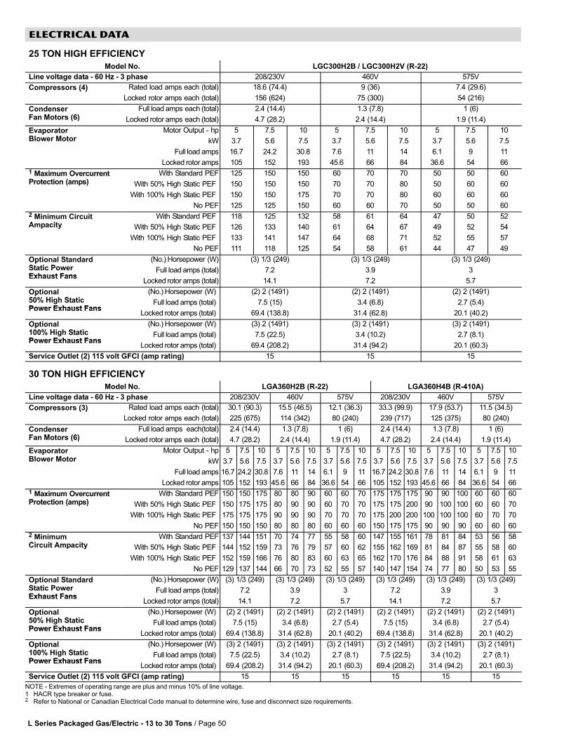
L Series Packaged Gas/Electric − 13 to 30 Tons / Page 50
ELECTRICAL DATA
25 TON HIGH EFFICIENCY
Model�No. LGC300H2B / LGC300H2V (R−22)
Line�voltage�data�−�60�Hz�−�3�phase 208/230V 460V 575V
Compressors (4) Rated load amps each (total) 18.6 (74.4) 9 (36) 7.4 (29.6)p ( )
Locked rotor amps each (total) 156 (624) 75 (300) 54 (216)
CondenserF M t (6)
Full�load�amps each�(total) 2.4 (14.4) 1.3 (7.8) 1 (6)Fan�Motors (6) Locked�rotor�amps each�(total) 4.7 (28.2) 2.4 (14.4) 1.9 (11.4)
EvaporatorBl M t
Motor Output − hp 5 7.5 10 5 7.5 10 5 7.5 10pBlower Motor kW 3.7 5.6 7.5 3.7 5.6 7.5 3.7 5.6 7.5
Full�load�amps 16.7 24.2 30.8 7.6 11 14 6.1 9 11
Locked�rotor�amps 105 152 193 45.6 66 84 36.6 54 66
1 Maximum OvercurrentP t ti ( )
With Standard PEF 125 150 150 60 70 70 50 50 60Protection (amps) With 50% High Static PEF 150 150 150 70 70 80 50 60 60
With 100% High Static PEF 150 150 175 70 70 80 60 60 60
No PEF 125 125 150 60 60 70 50 50 60
2 Minimum CircuitA it
With Standard PEF 118 125 132 58 61 64 47 50 52Ampacity With 50% High Static PEF 126 133 140 61 64 67 49 52 54
With 100% High Static PEF 133 141 147 64 68 71 52 55 57
No PEF 111 118 125 54 58 61 44 47 49
Optional StandardSt ti P
(No.)�Horsepower (W) (3) 1/3 (249) (3) 1/3 (249) (3) 1/3 (249)pStatic PowerExhaust Fans
Full�load�amps�(total) 7.2 3.9 3Exhaust Fans
Locked�rotor�amps�(total) 14.1 7.2 5.7
Optional50% Hi h St ti
(No.)�Horsepower (W) (2) 2 (1491) (2) 2 (1491) (2) 2 (1491)p50% High StaticPower Exhaust Fans
Full�load�amps�(total) 7.5 (15) 3.4 (6.8) 2.7 (5.4)Power Exhaust Fans
Locked�rotor�amps�(total) 69.4 (138.8) 31.4 (62.8) 20.1 (40.2)
Optional100% Hi h St ti
(No.)�Horsepower (W) (3) 2 (1491) (3) 2 (1491) (3) 2 (1491)p100% High StaticPower Exhaust Fans
Full�load�amps�(total) 7.5 (22.5) 3.4 (10.2) 2.7 (8.1)Power Exhaust Fans
Locked�rotor�amps�(total) 69.4 (208.2) 31.4 (94.2) 20.1 (60.3)
Service Outlet (2) 115 volt GFCI (amp rating) 15 15 15
30 TON HIGH EFFICIENCY
Model�No. LGA360H2B (R−22) LGA360H4B (R−410A)
Line�voltage�data�−�60�Hz�−�3�phase 208/230V 460V 575V 208/230V 460V 575V
Compressors (3) Rated load amps each (total) 30.1 (90.3) 15.5 (46.5) 12.1 (36.3) 33.3 (99.9) 17.9 (53.7) 11.5 (34.5)p ( )
Locked rotor amps each (total) 225 (675) 114 (342) 80 (240) 239 (717) 125 (375) 80 (240)
CondenserF M t (6)
Full�load�amps� each(total) 2.4 (14.4) 1.3 (7.8) 1 (6) 2.4 (14.4) 1.3 (7.8) 1 (6)Fan�Motors (6) Locked�rotor�amps each (total) 4.7 (28.2) 2.4 (14.4) 1.9 (11.4) 4.7 (28.2) 2.4 (14.4) 1.9 (11.4)
EvaporatorBl M t
Motor Output − hp 5 7.5 10 5 7.5 10 5 7.5 10 5 7.5 10 5 7.5 10 5 7.5 10pBlower Motor kW 3.7 5.6 7.5 3.7 5.6 7.5 3.7 5.6 7.5 3.7 5.6 7.5 3.7 5.6 7.5 3.7 5.6 7.5
Full�load�amps 16.7 24.2 30.8 7.6 11 14 6.1 9 11 16.7 24.2 30.8 7.6 11 14 6.1 9 11
Locked�rotor�amps 105 152 193 45.6 66 84 36.6 54 66 105 152 193 45.6 66 84 36.6 54 66
1 Maximum OvercurrentP t ti ( )
With Standard PEF 150 150 175 80 80 90 60 60 70 175 175 175 90 90 100 60 60 60Protection (amps) With 50% High Static PEF 150 175 175 80 90 90 60 70 70 175 175 200 90 100 100 60 60 70
With 100% High Static PEF 175 175 175 90 90 90 70 70 70 175 200 200 100 100 100 60 70 70
No PEF 150 150 150 80 80 80 60 60 60 150 175 175 90 90 90 60 60 60
2 MinimumCi it A it
With Standard PEF 137 144 151 70 74 77 55 58 60 147 155 161 78 81 84 53 56 58Circuit Ampacity With 50% High Static PEF 144 152 159 73 76 79 57 60 62 155 162 169 81 84 87 55 58 60
With 100% High Static PEF 152 159 166 76 80 83 60 63 65 162 170 176 84 88 91 58 61 63
No PEF 129 137 144 66 70 73 52 55 57 140 147 154 74 77 80 50 53 55
Optional StandardSt ti P
(No.)�Horsepower (W) (3) 1/3 (249) (3) 1/3 (249) (3) 1/3 (249) (3) 1/3 (249) (3) 1/3 (249) (3) 1/3 (249)pStatic PowerExhaust Fans
Full�load�amps�(total) 7.2 3.9 3 7.2 3.9 3Exhaust Fans
Locked�rotor�amps�(total) 14.1 7.2 5.7 14.1 7.2 5.7
Optional50% Hi h St ti
(No.)�Horsepower (W) (2) 2 (1491) (2) 2 (1491) (2) 2 (1491) (2) 2 (1491) (2) 2 (1491) (2) 2 (1491)p50% High StaticPower Exhaust Fans
Full�load�amps�(total) 7.5 (15) 3.4 (6.8) 2.7 (5.4) 7.5 (15) 3.4 (6.8) 2.7 (5.4)Power Exhaust Fans
Locked�rotor�amps�(total) 69.4 (138.8) 31.4 (62.8) 20.1 (40.2) 69.4 (138.8) 31.4 (62.8) 20.1 (40.2)
Optional100% Hi h St ti
(No.)�Horsepower (W) (3) 2 (1491) (3) 2 (1491) (3) 2 (1491) (3) 2 (1491) (3) 2 (1491) (3) 2 (1491)p100% High StaticPower Exhaust Fans
Full�load�amps�(total) 7.5 (22.5) 3.4 (10.2) 2.7 (8.1) 7.5 (22.5) 3.4 (10.2) 2.7 (8.1)Power Exhaust Fans
Locked�rotor�amps�(total) 69.4 (208.2) 31.4 (94.2) 20.1 (60.3) 69.4 (208.2) 31.4 (94.2) 20.1 (60.3)
Service Outlet (2) 115 volt GFCI (amp rating) 15 15 15 15 15 15
NOTE�− Extremes�of�operating�range�are�plus�and�minus�10%�of�line�voltage.1 HACR type breaker or fuse.2 Refer�to�National or Canadian�Electrical�Code�manual�to�determine�wire,�fuse�and�disconnect�size�requirements.
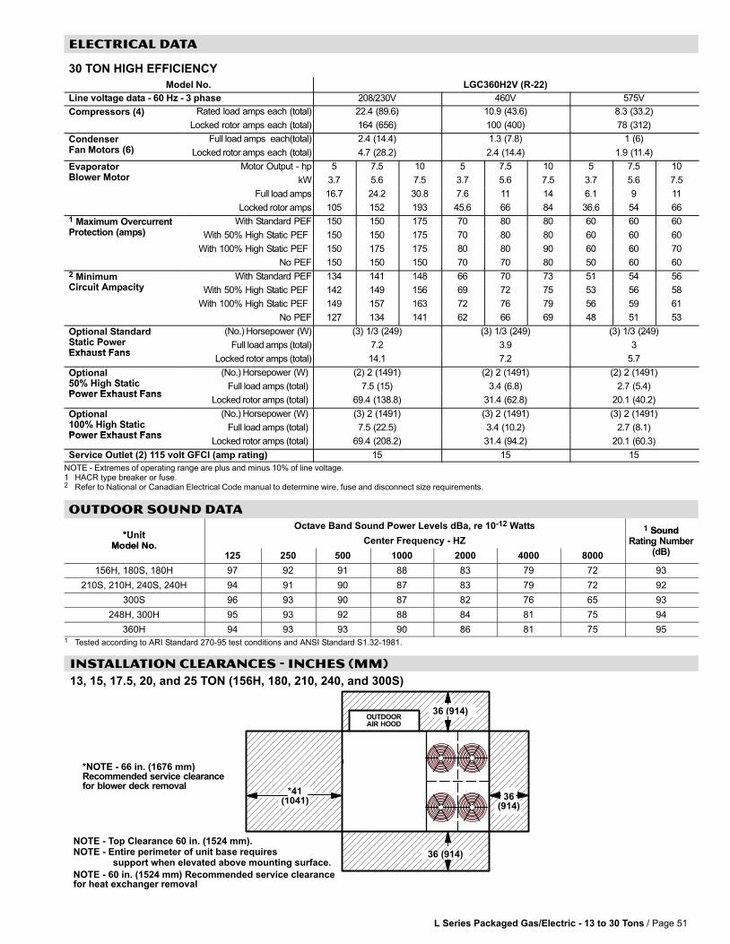
L Series Packaged Gas/Electric − 13 to 30 Tons / Page 51
ELECTRICAL DATA
30 TON HIGH EFFICIENCY
Model�No. LGC360H2V (R−22)
Line�voltage�data�−�60�Hz�−�3�phase 208/230V 460V 575V
Compressors (4) Rated load amps each (total) 22.4 (89.6) 10.9 (43.6) 8.3 (33.2)p ( )
Locked rotor amps each (total) 164 (656) 100 (400) 78 (312)
CondenserF M t (6)
Full�load�amps� each(total) 2.4 (14.4) 1.3 (7.8) 1 (6)Fan�Motors (6) Locked�rotor�amps each (total) 4.7 (28.2) 2.4 (14.4) 1.9 (11.4)
EvaporatorBl M t
Motor Output − hp 5 7.5 10 5 7.5 10 5 7.5 10pBlower Motor kW 3.7 5.6 7.5 3.7 5.6 7.5 3.7 5.6 7.5
Full�load�amps 16.7 24.2 30.8 7.6 11 14 6.1 9 11
Locked�rotor�amps 105 152 193 45.6 66 84 36.6 54 66
1 Maximum OvercurrentP t ti ( )
With Standard PEF 150 150 175 70 80 80 60 60 60Protection (amps) With 50% High Static PEF 150 150 175 70 80 80 60 60 60
With 100% High Static PEF 150 175 175 80 80 90 60 60 70
No PEF 150 150 150 70 70 80 50 60 60
2 MinimumCi it A it
With Standard PEF 134 141 148 66 70 73 51 54 56Circuit Ampacity With 50% High Static PEF 142 149 156 69 72 75 53 56 58
With 100% High Static PEF 149 157 163 72 76 79 56 59 61
No PEF 127 134 141 62 66 69 48 51 53
Optional StandardSt ti P
(No.)�Horsepower (W) (3) 1/3 (249) (3) 1/3 (249) (3) 1/3 (249)pStatic PowerExhaust Fans
Full�load�amps�(total) 7.2 3.9 3Exhaust Fans
Locked�rotor�amps�(total) 14.1 7.2 5.7
Optional50% Hi h St ti
(No.)�Horsepower (W) (2) 2 (1491) (2) 2 (1491) (2) 2 (1491)p50% High StaticPower Exhaust Fans
Full�load�amps�(total) 7.5 (15) 3.4 (6.8) 2.7 (5.4)Power Exhaust Fans
Locked�rotor�amps�(total) 69.4 (138.8) 31.4 (62.8) 20.1 (40.2)
Optional100% Hi h St ti
(No.)�Horsepower (W) (3) 2 (1491) (3) 2 (1491) (3) 2 (1491)p100% High StaticPower Exhaust Fans
Full�load�amps�(total) 7.5 (22.5) 3.4 (10.2) 2.7 (8.1)Power Exhaust Fans
Locked�rotor�amps�(total) 69.4 (208.2) 31.4 (94.2) 20.1 (60.3)
Service Outlet (2) 115 volt GFCI (amp rating) 15 15 15
NOTE�− Extremes�of�operating�range�are�plus�and�minus�10%�of�line�voltage.1 HACR type breaker or fuse.2 Refer�to�National or Canadian�Electrical�Code�manual�to�determine�wire,�fuse�and�disconnect�size�requirements.
OUTDOOR SOUND DATA
*UnitOctave Band Sound Power Levels dBa, re 10−12 Watts 1 Sound
*UnitModel No.
Center Frequency − HZ
1 SoundRating Number
(dB)Model No.
125 250 500 1000 2000 4000 8000
Rating Number(dB)
156H, 180S, 180H 97 92 91 88 83 79 72 93
210S, 210H, 240S, 240H 94 91 90 87 83 79 72 92
300S 96 93 90 87 82 76 65 93
248H, 300H 95 93 92 88 84 81 75 94
360H 94 93 93 90 86 81 75 951 Tested according to ARI Standard 270-95 test conditions and ANSI Standard S1.32-1981.
INSTALLATION CLEARANCES − INCHES (MM)
13, 15, 17.5, 20, and 25 TON (156H, 180, 210, 240, and 300S)
OUTDOORAIR HOOD
36 (914)
36(914)
36 (914)
*41(1041)
NOTE − 60 in. (1524 mm) Recommended service clearancefor heat exchanger removal
*NOTE − 66 in. (1676 mm)Recommended service clearancefor blower deck removal
NOTE − Top Clearance 60 in. (1524 mm).NOTE − Entire perimeter of unit base requires support when elevated above mounting surface.

L Series Packaged Gas/Electric − 13 to 30 Tons / Page 52
INSTALLATION CLEARANCES − INCHES (MM)
21, 25, and 30 TON (248H, 300H, and 360H) − Unit With Economizer
36(914)
36(914)
OUTDOORAIR HOOD
NOTE − 60 in. (1524 mm) Recommended ser-vice clearance for heat exchanger removal
*NOTE − 66 in. (1676 mm)Recommended service clearancefor blower deck removal
NOTE − Top Clearance 60 in. (1524 mm).NOTE − Entire perimeter of unit base requires support when elevated above mounting surface.
36 (914)
*41(1041)
21, 25, and 30 TON (248H, 300H, and 360H) − Unit With High Static Power Exhaust Fans
36(914)
OUTDOORAIR HOOD
NOTE − 60 in. (1524 mm) Recommended ser-vice clearance for heat exchanger removal
*NOTE − 66 in. (1676 mm)Recommended service clearancefor blower deck removal
NOTE − Top Clearance 60 in. (1524 mm).NOTE − Entire perimeter of unit base requires support when elevated above mounting surface.
36 (914)
80 (2032)
*41(1041)
21, 25, and 30 TON (248H, 300H, and 360H) − Unit With Horizontal Barometric Relief Dampers
36(914)
NOTE Allow adequate clearance for duct andbarometric relief damper installation.
NOTE Dampers may be installed on each sideof return air duct or end to end on one side ofreturn air duct.
OPTIONAL BAROMETRICRELIEF EXHAUST
DAMPERS(Field Installed
on Return Air Duct)
*41(1041)
OUTDOORAIR HOOD
NOTE − 60 in. (1524 mm) Recommended ser-vice clearance for heat exchanger removal
*NOTE − 66 in. (1676 mm)Recommended service clearancefor blower deck removal
NOTE − Top Clearance 60 in. (1524 mm).NOTE − Entire perimeter of unit base requires support when elevated above mounting surface. 36 (914)
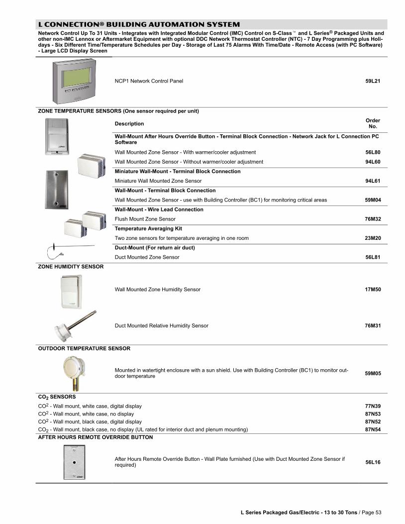
L Series Packaged Gas/Electric − 13 to 30 Tons / Page 53
L CONNECTION® BUILDING AUTOMATION SYSTEMNetwork Control Up To 31 Units − Integrates with Integrated Modular Control (IMC) Control on S−Class� and L Series® Packaged Units andother non−IMC Lennox or Aftermarket Equipment with optional DDC Network Thermostat Controller (NTC) − 7 Day Programming plus Holi-days − Six Different Time/Temperature Schedules per Day − Storage of Last 75 Alarms With Time/Date − Remote Access (with PC Software)− Large LCD Display Screen
NCP1 Network Control Panel 59L21
ZONE TEMPERATURE SENSORS (One sensor required per unit)
DescriptionOrder
No.
Wall−Mount After Hours Override Button − Terminal Block Connection − Network Jack for L Connection PCSoftware
Wall Mounted Zone Sensor − With warmer/cooler adjustment 56L80
Wall Mounted Zone Sensor − Without warmer/cooler adjustment 94L60
Miniature Wall−Mount − Terminal Block Connection
Miniature Wall Mounted Zone Sensor 94L61
Wall−Mount − Terminal Block Connection
Wall Mounted Zone Sensor − use with Building Controller (BC1) for monitoring critical areas 59M04
Wall−Mount − Wire Lead Connection
Flush Mount Zone Sensor 76M32
Temperature Averaging Kit
Two zone sensors for temperature averaging in one room 23M20
Duct−Mount (For return air duct)
Duct Mounted Zone Sensor 56L81
ZONE HUMIDITY SENSOR
Wall Mounted Zone Humidity Sensor 17M50
Duct Mounted Relative Humidity Sensor 76M31
OUTDOOR TEMPERATURE SENSOR
Mounted in watertight enclosure with a sun shield. Use with Building Controller (BC1) to monitor out-door temperature
59M05
CO2 SENSORS
CO2 − Wall mount, white case, digital display 77N39
CO2 − Wall mount, white case, no display 87N53
CO2 − Wall mount, black case, digital display 87N52
CO2 − Wall mount, black case, no display (UL rated for interior duct and plenum mounting) 87N54
AFTER HOURS REMOTE OVERRIDE BUTTON
After Hours Remote Override Button − Wall Plate furnished (Use with Duct Mounted Zone Sensor ifrequired)
56L16
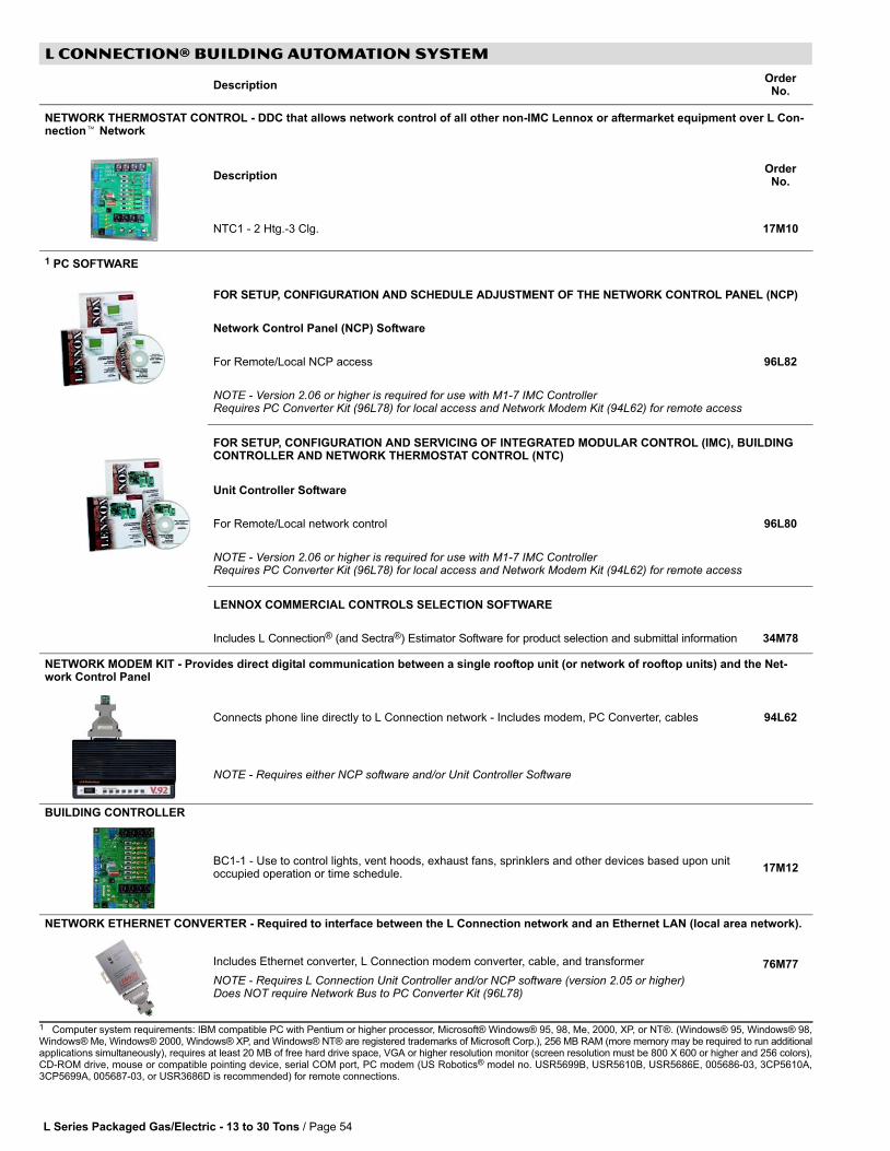
L Series Packaged Gas/Electric − 13 to 30 Tons / Page 54
L CONNECTION® BUILDING AUTOMATION SYSTEM
DescriptionOrder
No.
NETWORK THERMOSTAT CONTROL − DDC that allows network control of all other non−IMC Lennox or aftermarket equipment over L Con-nection� Network
DescriptionOrder
No.
NTC1 − 2 Htg.−3 Clg. 17M10
1 PC SOFTWARE
FOR SETUP, CONFIGURATION AND SCHEDULE ADJUSTMENT OF THE NETWORK CONTROL PANEL (NCP)
Network Control Panel (NCP) Software
For Remote/Local NCP access 96L82
NOTE − Version 2.06 or higher is required for use with M1−7 IMC ControllerRequires PC Converter Kit (96L78) for local access and Network Modem Kit (94L62) for remote access
FOR SETUP, CONFIGURATION AND SERVICING OF INTEGRATED MODULAR CONTROL (IMC), BUILDINGCONTROLLER AND NETWORK THERMOSTAT CONTROL (NTC)
Unit Controller Software
For Remote/Local network control 96L80
NOTE − Version 2.06 or higher is required for use with M1−7 IMC ControllerRequires PC Converter Kit (96L78) for local access and Network Modem Kit (94L62) for remote access
LENNOX COMMERCIAL CONTROLS SELECTION SOFTWARE
Includes L Connection® (and Sectra®) Estimator Software for product selection and submittal information 34M78
NETWORK MODEM KIT − Provides direct digital communication between a single rooftop unit (or network of rooftop units) and the Net-work Control Panel
Connects phone line directly to L Connection network − Includes modem, PC Converter, cables 94L62
NOTE − Requires either NCP software and/or Unit Controller Software
BUILDING CONTROLLER
BC1−1 − Use to control lights, vent hoods, exhaust fans, sprinklers and other devices based upon unitoccupied operation or time schedule.
17M12
NETWORK ETHERNET CONVERTER − Required to interface between the L Connection network and an Ethernet LAN (local area network).
Includes Ethernet converter, L Connection modem converter, cable, and transformer
NOTE − Requires L Connection Unit Controller and/or NCP software (version 2.05 or higher)Does NOT require Network Bus to PC Converter Kit (96L78)
76M77
1 Computer system requirements: IBM compatible PC with Pentium or higher processor, Microsoft® Windows® 95, 98, Me, 2000, XP, or NT®. (Windows® 95, Windows® 98,Windows® Me, Windows® 2000, Windows® XP, and Windows® NT® are registered trademarks of Microsoft Corp.), 256 MB RAM (more memory may be required to run additionalapplications simultaneously), requires at least 20 MB of free hard drive space, VGA or higher resolution monitor (screen resolution must be 800 X 600 or higher and 256 colors),CD−ROM drive, mouse or compatible pointing device, serial COM port, PC modem (US Robotics® model no. USR5699B, USR5610B, USR5686E, 005686−03, 3CP5610A,3CP5699A, 005687−03, or USR3686D is recommended) for remote connections.

L Series Packaged Gas/Electric − 13 to 30 Tons / Page 55
L CONNECTION® BUILDING AUTOMATION SYSTEM
DescriptionOrder
No.
kWH DEMAND CONTROLLER
Used with the Building Controller, the monitor sends a 24VAC output to a building control device to loadshed when electrical demand is high.
76M33
NOTE − Requires kWH meter with KYZ output.
AMBIENT LIGHT SENSOR
Use with the Building Controller and Network Control Panel for automatic lighting control 34M67
NEMA 1 ENCLOSURES
NEMA Enclosure 17M11
For Network Modem Kit or Building Controller 34M23
For Network Control Panel 34M24
NETWORK PHONE LINE AUTO−ROUTER
(Allows modem, fax and phone to share one line − routes signal to connect to device automatically)
Network Phone Line Auto−Router 34M22
NETWORK BUS TO PC CONVERTER KIT
Allows PC connection directly to L Connection® network − Required for any L Connection® PC software when used on a local network
NOTE − Not required for use with Ethernet Converter Kit (76M77)
96L78
COMMUNICATION CABLE
500 ft. Roll − RS−485 twisted pair communication wire − plenum rated 27M19
1 500 ft. Roll − RS−485 double twisted pair communication wire − plenum rated 76M76
1000 ft. Roll − RS−485 twisted pair communication wire − plenum rated 94L63
2500 ft. Roll − RS−485 twisted pair communication wire − plenum rated 68M25
1 Three wires are required for CO2 Sensors or Humidity Sensors.
NETWORK CONTROL PANEL WALL TRANSFORMER − Separate power supply for NCP (if desired)
Screw terminals
Transformer − 20VA, Class 2, Primary 120V, 60Hz, Secondary 24V 18M13
FACTORY INSTALLED COMPONENTS
Air Flow SwitchFactory
Dirty Filter Switch
FactoryInstalled
L Series Packaged Gas/Electric − 13 to 30 Tons / Page 56
SECTRA� COMMERCIAL ZONING SYSTEM − FACTORY INSTALLED
SECTRA SINGLE ZONE CONTROL
Module monitors and controls heating, cooling and economizer functions of Lennox’ S−Class� and L Series® rooftop equipment
configured for single−zone applications. Up to 50 zoned (bypass or VFD) and single zone (DDC or communicating thermostat) units
can be combined on a single Sectra Commercial Zoning System network (maximum of 120 LonWorks® nodes). Allows 2 stage
heat/3 stage cool demands to operate 1 four stages of cooling and heating by grouping compressors/heat stages in the factory IMC
configuration. Uses LonTalk protocol, conforming with LonMark® Rooftop Unit Functional Profile. Occupied, unoccupied, standby,
override, start−up and wait, cooling, heating, emergency heat, off, disabled, freeze protect, manual position, and fan−only modes.
Factory installed complete with return air temperature sensor and blower proving switch. Controls economizer damper via minimum
position, proportional free cooling (sensible, single enthalpy, or differential enthalpy), or demand control ventilation using an optional
carbon dioxide sensor. Supports modulating hydronic valves for heating and/or cooling. A total of one resistive analog input, two
binary inputs, and six relay outputs are available.
1 Sectra Single Zone Control is not compatible with the Four Stage Control Board (FS1).
SECTRA BYPASS CONTROL
Module monitors and controls heating, cooling and economizer functions of Lennox’ S−Class� and L Series® rooftop equipment
configured for pressure dependent constant volume bypass applications. Controls up to 18 zones per rooftop unit, with up to 50
combined zoned (bypass or VFD) and single zone (DDC or communicating thermostat) units on a single Sectra Commercial Zoning
System network (maximum of 120 LonWorks nodes). Allows 2 stage heat/3 stage cool demands to operate 1 four stages of cooling
and heating by grouping compressors/heat stages in the factory IMC configuration. Modulates bypass damper to maintain constant
static pressure input as zone dampers modulate. Occupied, unoccupied, vent and shutdown modes. Factory installed complete with
return air temperature sensor, discharge air temperature sensor, and blower proving switch. Controls economizer damper via mini-
mum position, proportional free cooling ( sensible, single enthalpy, or differential enthalpy), or demand control ventilation using an
optional carbon dioxide sensor. Supports modulating hydronic valves for heating and/or cooling. A total of eight analog inputs, eight
binary inputs, eight binary outputs, and six analog outputs are available.
1 Sectra Bypass Control is not compatible with the Four Stage Control Board (FS1).
SECTRA VFD CONTROL
Module works with the Integrated Modular Controller (IMC) control module to monitor and control heating and cooling functions of
Lennox’ S−Class� and L Series® rooftop equipment configured for pressure dependent, variable air volume applications with a fac-
tory mounted variable frequency drive (VFD). Controls up to 18 zones per rooftop unit, with up to 50 combined zoned (bypass or
VFD) and single zone (DDC or communicating thermostat) units on a single Sectra Commercial Zoning System network (maximum
of 120 LonWorks nodes). Module communicates with IMC using blower enable (G), occupied (OCP), discharge cooling enable
(Y1), and discharge heating enable (W1) digital outputs. IMC modulates VFD to maintain constant static pressure input as zone
dampers modulate. IMC controls 4 stage heat/4 stage cool 1 individually based on discharge air temperature input. Economizer,
demand control ventilation, power exhaust, and other unit functionality are controlled directly by the IMC.
1 Sectra Bypass Control is not compatible with the Four Stage Control Board (FS1).
AFTERMARKET ZONING SYSTEMS
See "Aftermarket Zoning System Interface" in the Controls Application Guide section of this document.
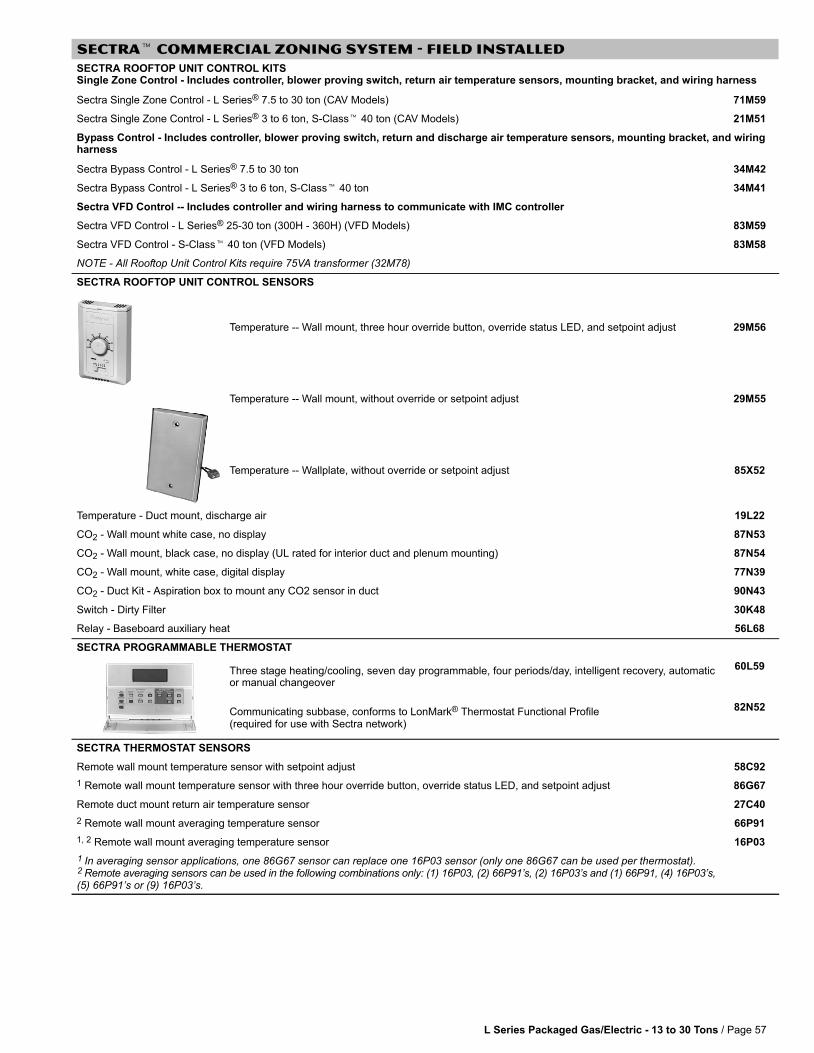
L Series Packaged Gas/Electric − 13 to 30 Tons / Page 57
SECTRA� COMMERCIAL ZONING SYSTEM − FIELD INSTALLED
SECTRA ROOFTOP UNIT CONTROL KITSSingle Zone Control − Includes controller, blower proving switch, return air temperature sensors, mounting bracket, and wiring harness
Sectra Single Zone Control − L Series® 7.5 to 30 ton (CAV Models) 71M59
Sectra Single Zone Control − L Series® 3 to 6 ton, S−Class� 40 ton (CAV Models) 21M51
Bypass Control − Includes controller, blower proving switch, return and discharge air temperature sensors, mounting bracket, and wiringharness
Sectra Bypass Control − L Series® 7.5 to 30 ton 34M42
Sectra Bypass Control − L Series® 3 to 6 ton, S−Class� 40 ton 34M41
Sectra VFD Control −− Includes controller and wiring harness to communicate with IMC controller
Sectra VFD Control − L Series® 25−30 ton (300H − 360H) (VFD Models) 83M59
Sectra VFD Control − S−Class� 40 ton (VFD Models) 83M58
NOTE − All Rooftop Unit Control Kits require 75VA transformer (32M78)
SECTRA ROOFTOP UNIT CONTROL SENSORS
Temperature −− Wall mount, three hour override button, override status LED, and setpoint adjust 29M56
Temperature −− Wall mount, without override or setpoint adjust 29M55
Temperature −− Wallplate, without override or setpoint adjust 85X52
Temperature − Duct mount, discharge air 19L22
CO2 − Wall mount white case, no display 87N53
CO2 − Wall mount, black case, no display (UL rated for interior duct and plenum mounting) 87N54
CO2 − Wall mount, white case, digital display 77N39
CO2 − Duct Kit − Aspiration box to mount any CO2 sensor in duct 90N43
Switch − Dirty Filter 30K48
Relay − Baseboard auxiliary heat 56L68
SECTRA PROGRAMMABLE THERMOSTAT
Three stage heating/cooling, seven day programmable, four periods/day, intelligent recovery, automaticor manual changeover
60L59
Communicating subbase, conforms to LonMark® Thermostat Functional Profile(required for use with Sectra network)
82N52
SECTRA THERMOSTAT SENSORS
Remote wall mount temperature sensor with setpoint adjust 58C92
1 Remote wall mount temperature sensor with three hour override button, override status LED, and setpoint adjust 86G67
Remote duct mount return air temperature sensor 27C40
2 Remote wall mount averaging temperature sensor 66P91
1, 2 Remote wall mount averaging temperature sensor 16P03
1 In averaging sensor applications, one 86G67 sensor can replace one 16P03 sensor (only one 86G67 can be used per thermostat).2 Remote averaging sensors can be used in the following combinations only: (1) 16P03, (2) 66P91’s, (2) 16P03’s and (1) 66P91, (4) 16P03’s,(5) 66P91’s or (9) 16P03’s.
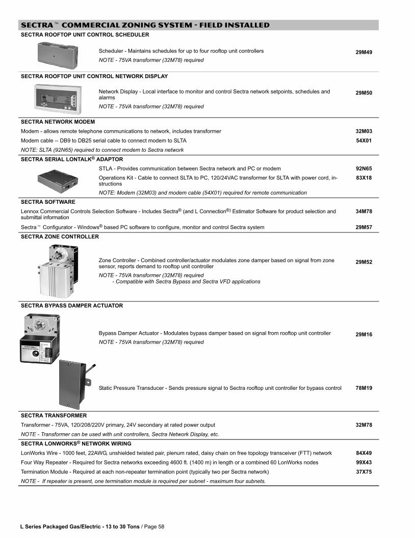
L Series Packaged Gas/Electric − 13 to 30 Tons / Page 58
SECTRA� COMMERCIAL ZONING SYSTEM − FIELD INSTALLED
SECTRA ROOFTOP UNIT CONTROL SCHEDULER
Scheduler − Maintains schedules for up to four rooftop unit controllers
NOTE − 75VA transformer (32M78) required
29M49
SECTRA ROOFTOP UNIT CONTROL NETWORK DISPLAY
Network Display − Local interface to monitor and control Sectra network setpoints, schedules andalarms
NOTE − 75VA transformer (32M78) required
29M50
SECTRA NETWORK MODEM
Modem − allows remote telephone communications to network, includes transformer 32M03
Modem cable −− DB9 to DB25 serial cable to connect modem to SLTA 54X01
NOTE: SLTA (92N65) required to connect modem to Sectra network
SECTRA SERIAL LONTALK® ADAPTOR
STLA − Provides communication between Sectra network and PC or modem 92N65
Operations Kit − Cable to connect SLTA to PC, 120/24VAC transformer for SLTA with power cord, in-structions
NOTE: Modem (32M03) and modem cable (54X01) required for remote communication
83X18
SECTRA SOFTWARE
Lennox Commercial Controls Selection Software − Includes Sectra® (and L Connection®) Estimator Software for product selection andsubmittal information
34M78
Sectra� Configurator − Windows® based PC software to configure, monitor and control Sectra system 29M57
SECTRA ZONE CONTROLLER
Zone Controller − Combined controller/actuator modulates zone damper based on signal from zonesensor, reports demand to rooftop unit controller
NOTE − 75VA transformer (32M78) required − Compatible with Sectra Bypass and Sectra VFD applications
29M52
SECTRA BYPASS DAMPER ACTUATOR
Bypass Damper Actuator − Modulates bypass damper based on signal from rooftop unit controller
NOTE − 75VA transformer (32M78) required
29M16
Static Pressure Transducer − Sends pressure signal to Sectra rooftop unit controller for bypass control 78M19
SECTRA TRANSFORMER
Transformer − 75VA, 120/208/220V primary, 24V secondary at rated power output 32M78
NOTE − Transformer can be used with unit controllers, Sectra Network Display, etc.
SECTRA LONWORKS® NETWORK WIRING
LonWorks Wire − 1000 feet, 22AWG, unshielded twisted pair, plenum rated, daisy chain on free topology transceiver (FTT) network 84X49
Four Way Repeater − Required for Sectra networks exceeding 4600 ft. (1400 m) in length or a combined 60 LonWorks nodes 99X43
Termination Module − Required at each non−repeater termination point (typically two per Sectra network) 37X75
NOTE − If repeater is present, one termination module is required per subnet − maximum four subnets.
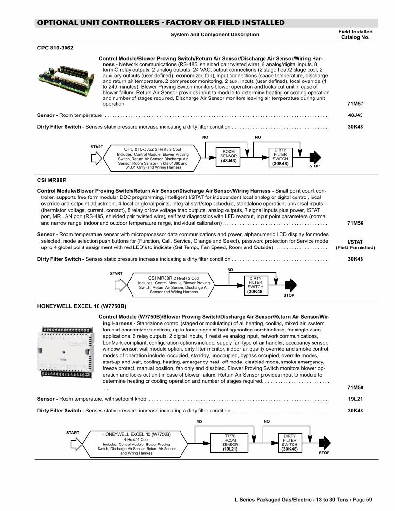
L Series Packaged Gas/Electric − 13 to 30 Tons / Page 59
OPTIONAL UNIT CONTROLLERS − FACTORY OR Field Installed
System and Component DescriptionField InstalledCatalog No.
CPC 810−3062
Control Module/Blower Proving Switch/Return Air Sensor/Discharge Air Sensor/Wiring Har-ness − Network communications (RS−485, shielded pair twisted wire), 8 analog/digital inputs, 8form−C relay outputs, 2 analog outputs, 24 VAC, output connections (2 stage heat/2 stage cool, 2auxiliary outputs (user defined), economizer, fan), input connections (space temperature, dischargeand return air temperature, 2 compressor monitoring, 2 aux. inputs (user defined), local override (1to 240 minutes), Blower Proving Switch monitors blower operation and locks out unit in case ofblower failure, Return Air Sensor provides input to module to determine heating or cooling operationand number of stages required, Discharge Air Sensor monitors leaving air temperature during unitoperation 71M57
Sensor − Room temperature . . . . . . . . . . . . . . . . . . . . . . . . . . . . . . . . . . . . . . . . . . . . . . . . . . . . . . . . . . . . . . . . . . . . . . . . . . . . . . . . . . . . . . . 48J43
Dirty Filter Switch − Senses static pressure increase indicating a dirty filter condition . . . . . . . . . . . . . . . . . . . . . . . . . . . . . . . . . . . . . . 30K48
ROOMSENSOR
(48J43)
DIRTYFILTER
SWITCH
(30K48)
CPC 810-3062 2 Heat�/�2 Cool
Includes: Control Module, Blower ProvingSwitch, Return Air Sensor, Discharge AirSensor, Room Sensor (in kits 61J80 and
61J81 Only) and Wiring Harness STOP
NO NO
START
CSI MR88R
Control Module/Blower Proving Switch/Return Air Sensor/Discharge Air Sensor/Wiring Harness − Small point count con-
troller, supports free-form modular DDC programming, intelligent I/STAT for independent local analog or digital control, local
override and setpoint adjustment, 4 local or global points, integral start/stop schedule, standalone operation, universal inputs
(thermistor, voltage, current, contact), 8 relay or low voltage triac outputs, analog outputs, 7 signal inputs plus power, ISTAT
port, MR LAN port (RS−485, shielded pair twisted wire), self test diagnostics with LED readout, input point parameters (normal
and narrow range, indoor and outdoor temperature range, individual calibration) . . . . . . . . . . . . . . . . . . . . . . . . . . . . . . . . . . . . . . . . . 71M56
Sensor − Room temperature sensor with microprocessor data communications and power, alphanumeric LCD display for modes
selected, mode selection push buttons for (Function, Call, Service, Change and Select), password protection for Service mode,
up to 4 global point assignment with red LED’s to indicate (Set Temp., Fan Speed, Room and Outside) . . . . . . . . . . . . . . . . . . . . . I/STAT
(Field Furnished)
Dirty Filter Switch − Senses static pressure increase indicating a dirty filter condition . . . . . . . . . . . . . . . . . . . . . . . . . . . . . . . . . . . . . . 30K48
DIRTYFILTER
SWITCH
(30K48)
CSI MR88R 2 Heat�/�2 Cool
Includes: Control Module, Blower ProvingSwitch, Return Air Sensor, Discharge Air
Sensor and Wiring HarnessSTOP
NOSTART
HONEYWELL EXCEL 10 (W7750B)
Control Module (W7750B)/Blower Proving Switch/Discharge Air Sensor/Return Air Sensor/Wir-
ing Harness − Standalone control (staged or modulating) of all heating, cooling, mixed air, system
fan and economizer functions, up to four stages of heating/cooling combinations, for single zone
applications, 6 relay outputs, 2 digital inputs, 1 resistive analog input, network communications,
LonMark compliant, configuration options include: supply fan type of air handler, occupancy sensor,
window sensor, wall module option, dirty filter monitor, indoor air quality override and smoke control.
modes of operation include: occupied, standby, unoccupied, bypass occupied, override modes,
start−up and wait, cooling, heating, emergency heat, off mode, disabled mode, smoke emergency,
freeze protect, manual position, fan only and disabled. Blower Proving Switch monitors blower op-
eration and locks out unit in case of blower failure, Return Air Sensor provides input to module to
determine heating or cooling operation and number of stages required. . . . . . . . . . . . . . . . . . . . . . . . . .
. . 71M59
Sensor − Room temperature, with setpoint knob . . . . . . . . . . . . . . . . . . . . . . . . . . . . . . . . . . . . . . . . . . . . . . . . . . . . . . . . . . . . . . . . . . . . . . 19L21
Dirty Filter Switch − Senses static pressure increase indicating a dirty filter condition . . . . . . . . . . . . . . . . . . . . . . . . . . . . . . . . . . . . . . 30K48
HONEYWELL EXCEL 10 (W7750B)4 Heat�/�4 Cool
Includes: Control Module, Blower ProvingSwitch, Discharge Air Sensor, Return Air Sensor
and Wiring Harness
T7770ROOM
SENSOR
(19L21)
DIRTYFILTER
SWITCH
(30K48)STOP
NO NO
START
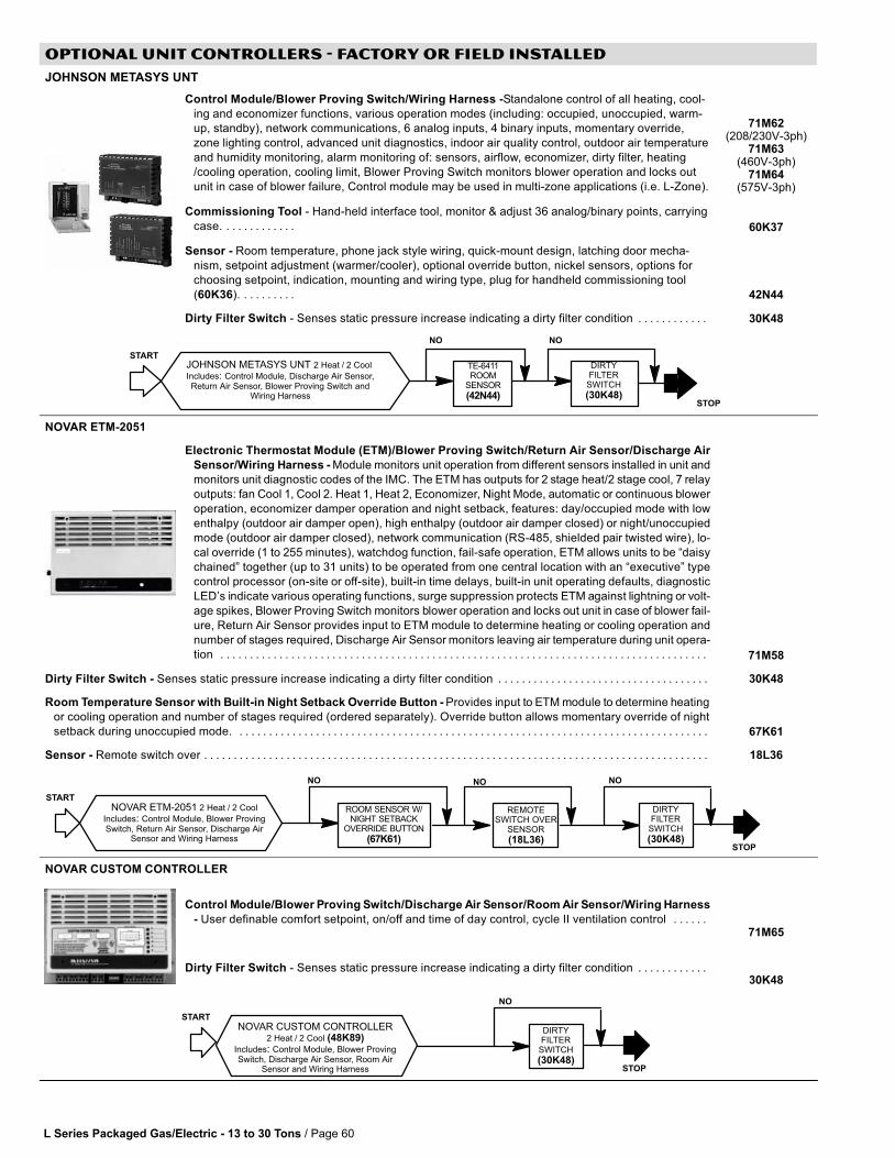
L Series Packaged Gas/Electric − 13 to 30 Tons / Page 60
OPTIONAL UNIT CONTROLLERS − Factory or Field Installed
JOHNSON METASYS UNT
Control Module/Blower Proving Switch/Wiring Harness −Standalone control of all heating, cool-
ing and economizer functions, various operation modes (including: occupied, unoccupied, warm-
up, standby), network communications, 6 analog inputs, 4 binary inputs, momentary override,
zone lighting control, advanced unit diagnostics, indoor air quality control, outdoor air temperature
and humidity monitoring, alarm monitoring of: sensors, airflow, economizer, dirty filter, heating
/cooling operation, cooling limit, Blower Proving Switch monitors blower operation and locks out
unit in case of blower failure, Control module may be used in multi−zone applications (i.e. L−Zone).
71M62(208/230V−3ph)
71M63(460V−3ph)
71M64(575V−3ph)
Commissioning Tool − Hand−held interface tool, monitor & adjust 36 analog/binary points, carrying
case. . . . . . . . . . . . . 60K37
Sensor − Room temperature, phone jack style wiring, quick−mount design, latching door mecha-
nism, setpoint adjustment (warmer/cooler), optional override button, nickel sensors, options for
choosing setpoint, indication, mounting and wiring type, plug for handheld commissioning tool
(60K36). . . . . . . . . . 42N44
Dirty Filter Switch − Senses static pressure increase indicating a dirty filter condition . . . . . . . . . . . . 30K48
JOHNSON METASYS UNT 2 Heat�/�2 Cool
Includes: Control Module, Discharge Air Sensor,Return Air Sensor, Blower Proving Switch and
Wiring Harness
TE-6411ROOM
SENSOR
(42N44)
DIRTYFILTER
SWITCH
(30K48)
NO
START
NO
STOP
NOVAR ETM−2051
Electronic Thermostat Module (ETM)/Blower Proving Switch/Return Air Sensor/Discharge Air
Sensor/Wiring Harness − Module monitors unit operation from different sensors installed in unit and
monitors unit diagnostic codes of the IMC. The ETM has outputs for 2 stage heat/2 stage cool, 7 relay
outputs: fan Cool 1, Cool 2. Heat 1, Heat 2, Economizer, Night Mode, automatic or continuous blower
operation, economizer damper operation and night setback, features: day/occupied mode with low
enthalpy (outdoor air damper open), high enthalpy (outdoor air damper closed) or night/unoccupied
mode (outdoor air damper closed), network communication (RS−485, shielded pair twisted wire), lo-
cal override (1 to 255 minutes), watchdog function, fail−safe operation, ETM allows units to be �daisy
chained" together (up to 31 units) to be operated from one central location with an �executive" type
control processor (on−site or off−site), built-in time delays, built-in unit operating defaults, diagnostic
LED’s indicate various operating functions, surge suppression protects ETM against lightning or volt-
age spikes, Blower Proving Switch monitors blower operation and locks out unit in case of blower fail-
ure, Return Air Sensor provides input to ETM module to determine heating or cooling operation and
number of stages required, Discharge Air Sensor monitors leaving air temperature during unit opera-
tion . . . . . . . . . . . . . . . . . . . . . . . . . . . . . . . . . . . . . . . . . . . . . . . . . . . . . . . . . . . . . . . . . . . . . . . . . . . . . . . . . . . 71M58
Dirty Filter Switch − Senses static pressure increase indicating a dirty filter condition . . . . . . . . . . . . . . . . . . . . . . . . . . . . . . . . . . . . 30K48
Room Temperature Sensor with Built−in Night Setback Override Button − Provides input to ETM module to determine heating
or cooling operation and number of stages required (ordered separately). Override button allows momentary override of night
setback during unoccupied mode. . . . . . . . . . . . . . . . . . . . . . . . . . . . . . . . . . . . . . . . . . . . . . . . . . . . . . . . . . . . . . . . . . . . . . . . . . . . . . . . . 67K61
Sensor − Remote switch over . . . . . . . . . . . . . . . . . . . . . . . . . . . . . . . . . . . . . . . . . . . . . . . . . . . . . . . . . . . . . . . . . . . . . . . . . . . . . . . . . . . . . . 18L36
NOVAR ETM-2051 2 Heat�/�2 Cool
Includes: Control Module, Blower ProvingSwitch, Return Air Sensor, Discharge Air
Sensor and Wiring Harness
ROOM SENSOR W/NIGHT SETBACK
OVERRIDE BUTTON
(67K61)
DIRTYFILTER
SWITCH
(30K48)
REMOTESWITCH OVER
SENSOR
(18L36)
START
NO
STOP
NONO
NOVAR CUSTOM CONTROLLER
Control Module/Blower Proving Switch/Discharge Air Sensor/Room Air Sensor/Wiring Harness
− User definable comfort setpoint, on/off and time of day control, cycle II ventilation control . . . . . . 71M65
Dirty Filter Switch − Senses static pressure increase indicating a dirty filter condition . . . . . . . . . . . . 30K48
DIRTYFILTER
SWITCH
(30K48)
NOVAR CUSTOM CONTROLLER2 Heat�/�2 Cool (48K89)
Includes: Control Module, Blower ProvingSwitch, Discharge Air Sensor, Room Air
Sensor and Wiring Harness
START
STOP
NO
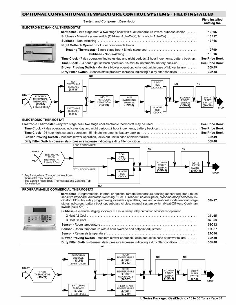
L Series Packaged Gas/Electric − 13 to 30 Tons / Page 61
OPTIONAL CONVENTIONAL TEMPERATURE CONTROL SYSTEMS − Field Installed
System and Component DescriptionField InstalledCatalog No.
ELECTRO-MECHANICAL THERMOSTAT
Thermostat − Two stage heat & two stage cool with dual temperature levers, subbase choice . . . . . . . 13F06
Subbase − Manual system switch (Off-Heat-Auto-Cool), fan switch (Auto-On) . . . . . . . . . . . . . . . . . . . 13F17
Subbase − Non-switching . . . . . . . . . . . . . . . . . . . . . . . . . . . . . . . . . . . . . . . . . . . . . . . . . . . . . . . . . . . . . . . . 13F16
Night Setback Operation − Order components below
Heating Thermostat − Single stage heat / Single stage cool . . . . . . . . . . . . . . . . . . . . . . . . . . . . . . . 12F99
Subbase − Non-switching . . . . . . . . . . . . . . . . . . . . . . . . . . . . . . . . . . . . . . . . . . . . . . 13F16
Time Clock − 7 day operation, indicates day and night periods, 2 hour increments, battery back-up . See Price Book
Time Clock − 24 hour night setback operation, 15 minute increments, battery back-up . . . . . . . . . . . . See Price Book
Blower Proving Switch − Monitors blower operation, locks out unit in case of blower failure . . . . . . 30K49
Dirty Filter Switch − Senses static pressure increase indicating a dirty filter condition . . . . . . . . . . . . 30K48
24 HOURTIME
CLOCK
ELECTROMECHANICALTHERMOSTAT
(13F06)2 Heat�−�2 Cool
NONSWITCHINGSUBBASE
(13F16)
SWITCHINGSUBBASE
(13F17)
NIGHTTHERMOSTAT1 Heat/1 Cool
(12F99)
NONSWITCHINGSUBBASE
(13F16)
7 DAYTIME
CLOCK
BLOWERPROVESWITCH
(30K49)
DIRTYFILTER
SWITCH
(30K48)
NO
STOP
START
NO NO
ELECTRONIC THERMOSTAT
Electronic Thermostat − Any two stage heat/ two stage cool electronic thermostat may be used. . . . . . . . . . . . . . . . . . . . . . . . . . . . See Price Book
Time Clock − 7 day operation, indicates day and night periods, 2 hour increments, battery back-up . . . . . . . . . . . . . . . . . . . . . . . . . See Price Book
Time Clock − 24 hour night setback operation, 15 minute increments, battery back-up . . . . . . . . . . . . . . . . . . . . . . . . . . . . . . . . . . . . See Price Book
Blower Proving Switch − Monitors blower operation, locks out unit in case of blower failure . . . . . . . . . . . . . . . . . . . . . . . . . . . . . . 30K49
Dirty Filter Switch − Senses static pressure increase indicating a dirty filter condition . . . . . . . . . . . . . . . . . . . . . . . . . . . . . . . . . . . . 30K48
*ELECTRONICROOM
THERMOSTAT2 Heat�−�2 Cool
24 HOURTIME
CLOCK
7 DAYTIME
CLOCK
BLOWERPROVESWITCH
(30K49)
DIRTYFILTER
SWITCH
(30K48)STOP
STARTNO NO
LESS ECONOMIZER
WITH ECONOMIZER
NO
* Any 2 stage heat/ 2 stage cool electronicthermostat may be used.See Lennox Price Book, Thermostats and Controls, Tab for selection.
PROGRAMMABLE COMMERCIAL THERMOSTAT
Thermostat − Programmable, internal or optional remote temperature sensing (sensor required), touchsensitive keyboard, automatic switching, �F or �C readout, no anticipator, droop/no droop selection, in-dicator LED’s, hour/day programming, override capabilities, time and operational mode readout, stagestatus indicators, battery back-up, subbase choice, manual system switch (Heat-Off-Auto-Cool), fanswitch (Auto-On) . .
59N27
Subbase − Selectable staging, indicator LED’s, auxiliary relay output for economizer operation
2 Heat / 2 Cool . . . . . . . . . . . . . . . . . . . . . . . . . . . . . . . . . . . . . . . . . . . . . . . . . . . . . . . . . . . . . . . . . . . . . . . 37L55
3 Heat / 3 Cool . . . . . . . . . . . . . . . . . . . . . . . . . . . . . . . . . . . . . . . . . . . . . . . . . . . . . . . . . . . . . . . . . . . . . . . 37L53
Sensor − Room temperature . . . . . . . . . . . . . . . . . . . . . . . . . . . . . . . . . . . . . . . . . . . . . . . . . . . . . . . . . . . . . . 58C92
Sensor − Room temperature with 3 hour override and setpoint adjustment . . . . . . . . . . . . . . . . . . . . . . 86G67
Sensor − Return air temperature . . . . . . . . . . . . . . . . . . . . . . . . . . . . . . . . . . . . . . . . . . . . . . . . . . . . . . . . . . 27C40
Blower Proving Switch − Monitors blower operation, locks out unit in case of blower failure . . . . . . 30K49
Dirty Filter Switch − Senses static pressure increase indicating a dirty filter condition . . . . . . . . . . . . 30K48
SWITCHINGSUBBASE
(37L53)3 Heat�−�3 Cool
SWITCHINGSUBBASE
(37L55)2 Heat�−�2 Cool
ROOMTEMPERATURE
SENSORW/OVERRIDE
(86G67)
ROOMTEMPERATURE
SENSOR
(58C92)
RETURN AIRTEMPERATURE
SENSOR
(27C40)
T7300THERMOSTAT
(59N27)
BLOWERPROVESWITCH
(30K49)
DIRTYFILTER
SWITCH
(30K48)
NO
STOP
START
NO NO
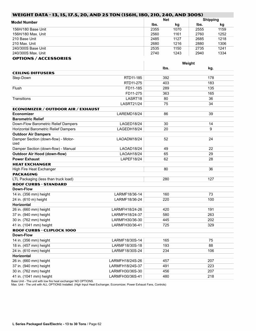
L Series Packaged Gas/Electric − 13 to 30 Tons / Page 62
WEIGHT DATA − 13, 15, 17.5, 20, and 25 TON (156H, 180, 210, 240, and 300S)
Model NumberNet Shipping
Model Numberlbs. kg lbs. kg
156H/180 Base Unit 2355 1070 2555 1159
156H/180 Max. Unit 2560 1161 2760 1252
210 Base Unit 2485 1127 2685 1218
210 Max. Unit 2680 1216 2880 1306
240/300S Base Unit 2535 1150 2735 1241
240/300S Max. Unit 2740 1243 2940 1334
OPTIONS / ACCESSORIESWeight
lbs. kg.
CEILING DIFFUSERS
Step−Down RTD11−185 392 178p
RTD11−275 403 183
Flush FD11−185 289 135
FD11−275 363 165
Transitions LASRT18 80 36
LASRT21/24 75 34
ECONOMIZER / OUTDOOR AIR / EXHAUST
Economizer LAREMD18/24 86 39
Barometric Relief
Down−Flow Barometric Relief Dampers LAGED18/24 30 14
Horizontal Barometric Relief Dampers LAGEDH18/24 20 9
Outdoor Air Dampers
Damper Section (down−flow) − Motor-ized
LAOADM18/24 52 24
Damper Section (down−flow) − Manual LAOAD18/24 49 22
Outdoor Air Hood (down−flow) LAOAH18/24 65 29
Power Exhaust LAPEF18/24 62 28
HEAT EXCHANGER
High Fire Heat Exchanger 80 36
PACKAGING
LTL Packaging (less than truck load) 280 127
ROOF CURBS − STANDARD
Down−Flow
14 in. (356 mm) height LARMF18/36−14 160 73
24 in. (610 m) height LARMF18/36−24 220 100
Horizontal
26 in. (660 mm) height LARMFH18/24−26 420 191
37 in. (940 mm) height LARMFH18/24−37 580 263
30 in. (762 mm) height LARMFH30/36−30 445 202
41 in. (1041 mm) height LARMFH30/36−41 725 329
ROOF CURBS − CLIPLOCK 1000
Down−Flow
14 in. (356 mm) height LARMF18/30S−14 165 75
18 in. (457 mm) height LARMF18/30S−18 193 88
24 in. (610 mm) height LARMF18/30S−24 234 106
Horizontal
26 in. (660 mm) height LARMFH18/24S−26 457 207
37 in. (940 mm) height LARMFH18/24S−37 491 223
30 in. (762 mm) height LARMFH30/36S−30 456 207
41 in. (1041 mm) height LARMFH30/36S−41 480 218
Base Unit − The unit with low fire heat exchanger NO OPTIONS.Max. Unit − The unit with ALL OPTIONS Installed. (High Input Heat Exchanger, Economizer, Power Exhaust Fans, Controls)

L Series Packaged Gas/Electric − 13 to 30 Tons / Page 63
WEIGHT DATA − 21, 25, and 30 TON (248H, 300H, and 360H)
Model NumberNet Shipping
Model Numberlbs. kg lbs. kg
248H/300H Base Unit 3020 1370 3230 1465
248H/300H Max. Unit 3340 1515 3450 1565
360 Base Unit 3330 1510 3540 1606
360 Max. Unit 3640 1651 3750 1701
OPTIONS / ACCESSORIESWeight
lbs. kg.
CEILING DIFFUSERS
Step−Down LARTD30/36 437 198
Flush LAFD30/36 414 188
Transitions LASRT30/36 85 39
ECONOMIZER/OUTDOOR AIR
Economizer LAREMD30/36 119 54
Barometric Relief
Down−Flow Barometric Relief Dampers LAGED30/36 45 20
Horizontal Barometric Relief Dampers LAGEDH30/36 20 9
Outdoor Air Dampers
Damper Section (down−flow) − Motor-ized
LAOADM30/36 72 33
Damper Section (down−flow) − Manual LAOAD30/36 68 31
Outdoor Air Hood (down−flow) LAOAH30/36 76 34
Power Exhaust
Power Exhaust LAPEF30/36 99 45
50% High Static − LAPEB30/36DY 400 181
100% High Static with or without VFD − LAPEB30/36 465 211
HEAT EXCHANGER
High Fire Heat Exchanger 80 36
PACKAGING
LTL Packaging (less than truck load) 300 136
ROOF CURBS − STANDARD
Down−Flow
14 in. (356 mm) height LARMF18/36−14 160 73
24 in. (610 m) height LARMF18/36−24 220 100
Horizontal
30 in. (762 mm) height LARMFH30/36−30 445 202
41 in. (1041 mm) height LARMFH30/36−41 725 329
ROOF CURBS − CLIPLOCK 1000
Down−Flow
14 in. (356 mm) height LARMF30/36S−14 149 68
18 in. (457 mm) height LARMF30/36S−18 204 93
24 in. (610 mm) height LARMF30/36S−24 248 112
Horizontal
30 in. (762 mm) height LARMFH30/36S−30 456 207
41 in. (1041 mm) height LARMFH30/36S−41 480 218
Base Unit − The unit with low fire heat exchanger NO OPTIONS.Max. Unit − The unit with ALL OPTIONS Installed. (High Input Heat Exchanger, Economizer, Power Exhaust Fans, Controls)
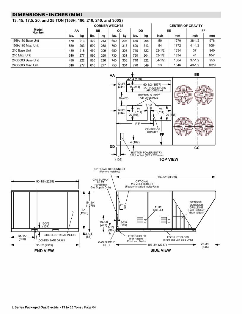
L Series Packaged Gas/Electric − 13 to 30 Tons / Page 64
DIMENSIONS − INCHES (MM)
13, 15, 17.5, 20, and 25 TON (156H, 180, 210, 240, and 300S)
CORNER WEIGHTS CENTER OF GRAVITY
ModelNumber
AA BB CC DD EE FFNumber
lbs. kg lbs. kg lbs. kg lbs. kg inch mm inch mm
156H/180 Base Unit 470 213 470 213 650 295 650 295 50 1270 38−1/2 978
156H/180 Max. Unit 580 263 590 268 700 318 690 313 54 1372 41-1/2 1054
210 Base Unit 480 218 460 209 680 308 710 322 52-1/2 1334 37 940
210 Max. Unit 610 277 590 268 730 331 750 304 52-1/2 1334 41 1041
240/300S Base Unit 490 222 520 236 740 336 710 322 54-1/2 1384 37-1/2 953
240/300S Max. Unit 610 277 610 277 750 304 770 349 53 1346 40-1/2 1029
BOTTOM POWER ENTRY5 X 8 inches (127 X 203 mm)
BOTTOM SUPPLYAIR OPENINGS
BOTTOM RETURNAIR OPENING
4-1/4 (108)
4-1/2(114)
28(711)
28(711)
4 (102)
4(102)
12-3/8(314)
12-3/8(314)
20 (508) 20 (508)
15 (381)
18 (457)
60-1/2 (1537)
AA BB
CCDD
CENTER OFGRAVITY
EE
FF
SIDE VIEW
TOP VIEW
END VIEW
FORKLIFT SLOTS(Front and Left Side Only)
90-1/8 (2289)
31-1/2(800)
132-5/8 (3369)
LIFTING HOLES(For Rigging
Front and Back)CONDENSATE DRAIN
5-3/8(137)
OPTIONAL DISCONNECT(Factory Installed)
OPTIONAL115 VOLT OUTLET
(Factory Installed Inside Unit)
FLUEOUTLET
3-1/4(83)
54-1/4(1378)
51(1295)
GAS SUPPLYINLET
(For BottomGas Supply Only)
5-7/8(149)
19-3/8(492)
1-1/2(38)
91-1/8 (2315) 107-3/4 (2737)
SIDE ELECTRICAL INLETS
25-3/8(645)
OPTIONALOUTDOORGRILLE KIT
(Field Installed)(Both Sides)
GAS SUPPLYINLET
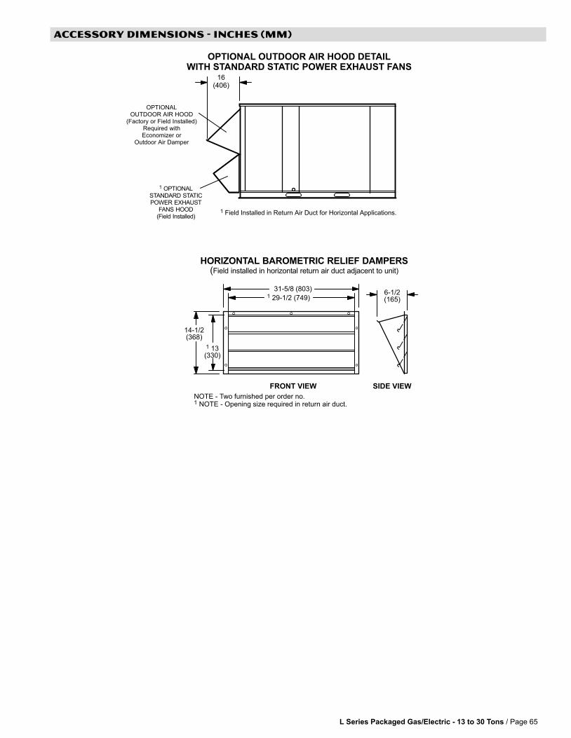
L Series Packaged Gas/Electric − 13 to 30 Tons / Page 65
ACCESSORY DIMENSIONS − INCHES (MM)
FRONT VIEW SIDE VIEW
31−5/8 (803)
14-1/2(368)
1 13(330)
6-1/2(165)
1 29−1/2 (749)
NOTE − Two furnished per order no. 1 NOTE − Opening size required in return air duct.
HORIZONTAL BAROMETRIC RELIEF DAMPERS(Field installed in horizontal return air duct adjacent to unit)
1 OPTIONALSTANDARD STATICPOWER EXHAUST
FANS HOOD(Field Installed)
OPTIONAL OUTDOOR AIR HOOD DETAILWITH STANDARD STATIC POWER EXHAUST FANS
16(406)
OPTIONALOUTDOOR AIR HOOD
(Factory or Field Installed)Required withEconomizer or
Outdoor Air Damper
1 Field Installed in Return Air Duct for Horizontal Applications.
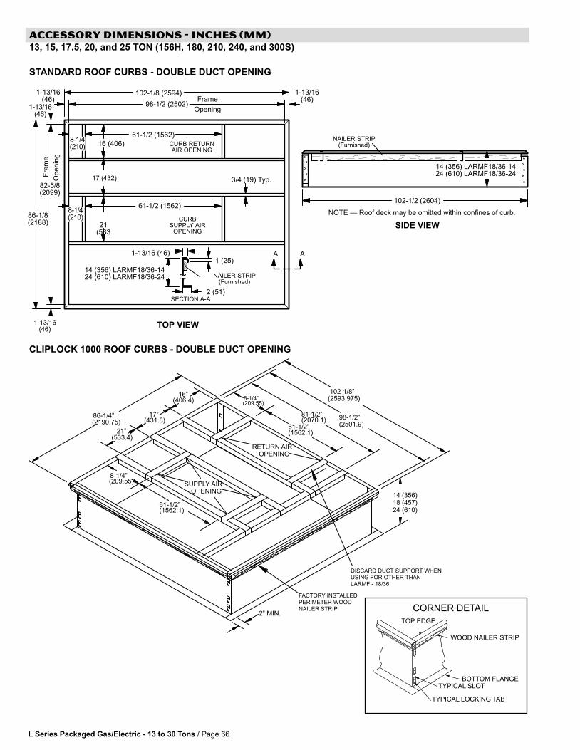
L Series Packaged Gas/Electric − 13 to 30 Tons / Page 66
ACCESSORY DIMENSIONS − INCHES (MM)13, 15, 17.5, 20, and 25 TON (156H, 180, 210, 240, and 300S)
STANDARD ROOF CURBS − DOUBLE DUCT OPENING
1 (25)
2 (51)SECTION A-A
1-13/16 (46)
NOTE � Roof deck may be omitted within confines of curb.
SIDE VIEW
NAILER STRIP(Furnished)
14 (356) LARMF18/36-1424 (610) LARMF18/36-24
CURB RETURNAIR OPENING
CURBSUPPLY AIR
OPENING
TOP VIEW
Fra
me
Openin
g
Frame
Opening
17 (432)
21(533
)
16 (406)
102-1/8 (2594)
61-1/2 (1562)
98-1/2 (2502)
86-1/8(2188)
82-5/8(2099)
102-1/2 (2604)
1-13/16(46)
AA
NAILER STRIP(Furnished)
3/4 (19) Typ.
14 (356) LARMF18/36-1424 (610) LARMF18/36-24
1-13/16(46)
1-13/16(46)
1-13/16(46)
61−1/2 (1562)
8−1/4(210)
8−1/4(210)
CLIPLOCK 1000 ROOF CURBS − DOUBLE DUCT OPENING
TOP EDGE
BOTTOM FLANGE
TYPICAL LOCKING TAB
TYPICAL SLOT
WOOD NAILER STRIP
CORNER DETAIL
FACTORY INSTALLEDPERIMETER WOODNAILER STRIP
86−1/4"
102−1/8"
61−1/2"
OPENINGRETURN AIR
SUPPLY AIROPENING
8−1/4"
98−1/2"
16"
17"
21"
8−1/4"
61−1/2"
81−1/2"
DISCARD DUCT SUPPORT WHENUSING FOR OTHER THANLARMF − 18/36
2" MIN.
(2190.75)
(533.4)
(431.8)
(406.4)(209.55)
(1562.1)
(2070.1)(2501.9)
(2593.975)
(209.55)
(1562.1)
14 (356)18 (457)24 (610)
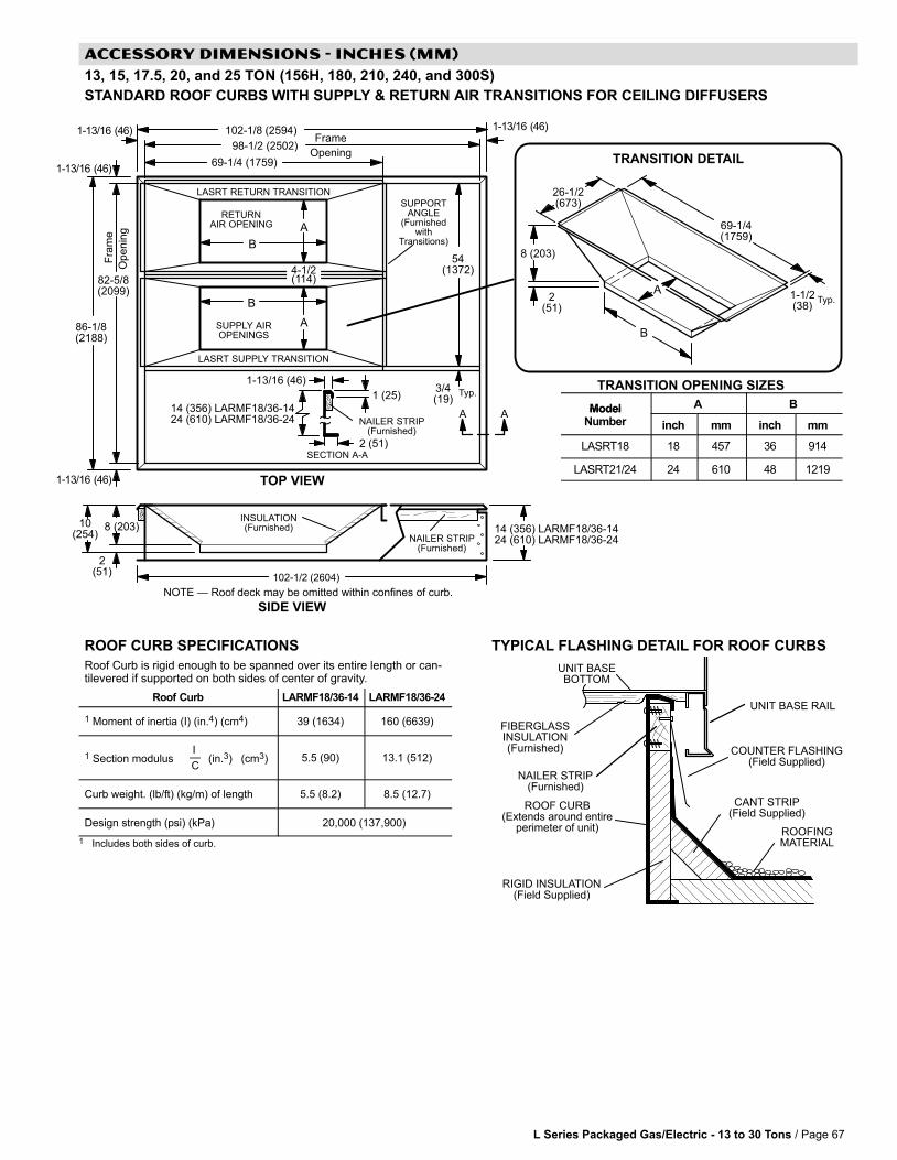
1 (25)
2 (51)SECTION A-A
1-13/16 (46)
SIDE VIEW
NAILER STRIP(Furnished)
RETURNAIR OPENING
SUPPLY AIROPENINGS
TOP VIEW
Fra
me
Openin
g
Frame
Opening
54(1372)
102-1/8 (2594)
69-1/4 (1759)
98-1/2 (2502)
86-1/8(2188)
82-5/8(2099)
102-1/2 (2604)
AANAILER STRIP
(Furnished)
3/4(19)
Typ.
4-1/2(114)
LASRT RETURN TRANSITION
LASRT SUPPLY TRANSITION
SUPPORTANGLE
(Furnishedwith
Transitions)
INSULATION(Furnished)
2(51)
10(254)
8 (203)
A
B
B
A
14 (356) LARMF18/36-1424 (610) LARMF18/36-24
14 (356) LARMF18/36-1424 (610) LARMF18/36-24
A
B
69-1/4(1759)
2(51)
8 (203)
26-1/2(673)
1-1/2(38)
Typ.
TRANSITION OPENING SIZES
NOTE � Roof deck may be omitted within confines of curb.
TRANSITION DETAIL
1-13/16 (46)
1-13/16 (46)
1-13/16 (46) 1-13/16 (46)
L Series Packaged Gas/Electric − 13 to 30 Tons / Page 67
ACCESSORY DIMENSIONS − INCHES (MM)
13, 15, 17.5, 20, and 25 TON (156H, 180, 210, 240, and 300S)
STANDARD ROOF CURBS WITH SUPPLY & RETURN AIR TRANSITIONS FOR CEILING DIFFUSERS
Model A BModelNumber inch mm inch mm
LASRT18 18 457 36 914
LASRT21/24 24 610 48 1219
ROOF CURB SPECIFICATIONS
Roof Curb is rigid enough to be spanned over its entire length or can-tilevered if supported on both sides of center of gravity.
Roof Curb LARMF18/36-14 LARMF18/36-24
1 Moment of inertia (I) (in.4) (cm4) 39 (1634) 160 (6639)
1 Section modulusI�C
(in.3) (cm3) 5.5 (90) 13.1 (512)
Curb weight. (lb/ft) (kg/m) of length 5.5 (8.2) 8.5 (12.7)
Design strength (psi) (kPa) 20,000 (137,900)
1 Includes both sides of curb.
TYPICAL FLASHING DETAIL FOR ROOF CURBS
ROOF CURB(Extends around entire
perimeter of unit)
FIBERGLASSINSULATION(Furnished) COUNTER FLASHING
(Field Supplied)
UNIT BASEBOTTOM
RIGID INSULATION(Field Supplied)
ROOFINGMATERIAL
CANT STRIP(Field Supplied)
NAILER STRIP(Furnished)
UNIT BASE RAIL

L Series Packaged Gas/Electric − 13 to 30 Tons / Page 68
ACCESSORY DIMENSIONS − INCHES (MM)
13, 15, 17.5, 20, and 25 TON (156H, 180, 210, 240, and 300S)
HORIZONTAL ROOF CURBS − Requires Optional Horizontal Return Air Panel Kit
1 LARMFH18/24-26 2 LARMFH18/24-37 3 LARMFH30/36-30 (used with 300S/300H/360 Models) 4 LARMFH30/36-40 (used with 300S/300H/360 Models)
102-1/8 (2594)
SIDE VIEW
TOP VIEW
Fra
me
Op
en
ing
Frame
Opening
54(1372)
98-1/2 (2502)
82-5/8(2099)
86-5/8 (2200)
98-1/2 (2502)
FRONT VIEW
NAILER STRIP(Furnished)
102-1/2 (2604)
CURB SUPPLYAIR OPENING
With 1-1/2 in. (38 mm) FLANGE
75(1905)
5-1/2 (140)
SUPPLYDUCT
PANELS(Furnished)
SUPPLY AIRTURNING VANE
(Furnished)
1 (25)
2 (51)SECTION A-A
1-13/16 (46)
NAILER STRIP(Furnished)
AA
102-1/8 (2594) 86-1/4 (2191)
NOTE − Roof deck may be omitted within confines of curb.
SUPPLY AIRTURNING VANE
(Furnished)
PANEL TO COVER RETURN AIR OPENING IN BOTTOM OF UNIT(Furnished With Optional Horizontal Return Air Panel Kit)
SIDE VIEW(PACKAGED UNIT)
86-1/8(2188)
1-13/16 (46)
1-13/16(46)
1-13/16 (46)1-13/16 (46)
NOTE LARMFH18/24-26 and LARMFH30/36-30are designed for horizontal dischargewhen unit is mounted on a slab.LARMFH18/24-37 and LARMFH30/36-41are designed for horizontal dischargewhen unit is mounted on a rooftop.
1,2 8-1/4 (210)3,4 13-1/4 (337)
1,3 6-1/2 (165)2,4 17-1/2 (445)
1 26 (660)2 37 (940)3 30 (762)4 41 (1041)
1,2 14 (356)3,4 18 (457)
1 26 (660)2 37 (940)3 30 (762)4 41 (1041)
HORIZONTALSUPPLY AIR OPENING
HORIZONTAL ROOF CURB(Required For Horizontal Applications)
1,2 8-1/4 (210)3,4 13-1/4 (337)
75 (1905)
HORIZONTAL RETURNAIR OPENING
12-3/8(314)15 (381)
60-1/2 (1537)
2 (51)
54-1/4(1378)
NOTE − Top of Roof Curb extends 4 inch(102 mm) inside bottom of unit base. SeeTypical flashing detail.
OPTIONAL RETURN AIR PANEL KIT(Required For
Horizontal Applications)
1,3 6-1/2 (165)2,4 17-1/2 (445)
1 22 (559)2 33 (838)3 26 (660)4 37 (940)
1 76-1/4 (1937)2 87-1/4 (2216)3 80-1/4 (2038)4 91-1/4 (2318)
1,2 14 (356)3,4 18 (457)
30-3/8(772)
HORIZONTAL SUPPLY AND RETURN AIR OPENINGSWITH HORIZONTAL ROOF CURB
1 LARMFH18/24-26 2 LARMFH18/24-373 LARMFH30/36-30 (used with 300S Models Only)4 LARMFH30/36-40 (used with 300S Models Only)
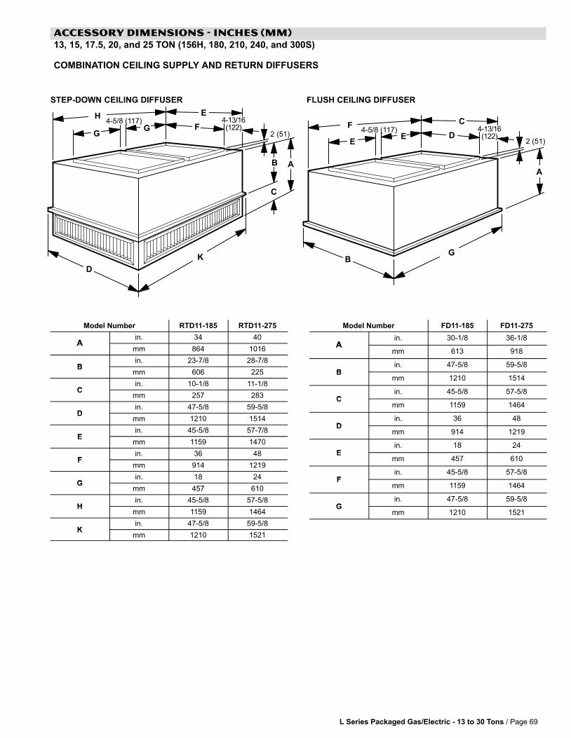
L Series Packaged Gas/Electric − 13 to 30 Tons / Page 69
ACCESSORY DIMENSIONS − INCHES (MM)13, 15, 17.5, 20, and 25 TON (156H, 180, 210, 240, and 300S)
COMBINATION CEILING SUPPLY AND RETURN DIFFUSERS
2 (51)2 (51)
AB
C
D
F
A
B
C
D
E
STEP-DOWN CEILING DIFFUSER FLUSH CEILING DIFFUSER
GG
H
K
EE
F
G
4−13/16(122)
4−13/16(122)
4−5/8 (117)
4−5/8 (117)
Model Number RTD11−185 RTD11−275
Ain. 34 40
Amm 864 1016
Bin. 23−7/8 28−7/8
Bmm 606 225
Cin. 10−1/8 11−1/8
Cmm 257 283
Din. 47−5/8 59−5/8
Dmm 1210 1514
Ein. 45−5/8 57−7/8
Emm 1159 1470
Fin. 36 48
Fmm 914 1219
Gin. 18 24
Gmm 457 610
Hin. 45−5/8 57−5/8
Hmm 1159 1464
Kin. 47−5/8 59−5/8
Kmm 1210 1521
Model Number FD11−185 FD11−275
Ain. 30−1/8 36−1/8
Amm 613 918
Bin. 47−5/8 59−5/8
Bmm 1210 1514
Cin. 45−5/8 57−5/8
Cmm 1159 1464
Din. 36 48
Dmm 914 1219
Ein. 18 24
Emm 457 610
Fin. 45−5/8 57−5/8
Fmm 1159 1464
Gin. 47−5/8 59−5/8
Gmm 1210 1521
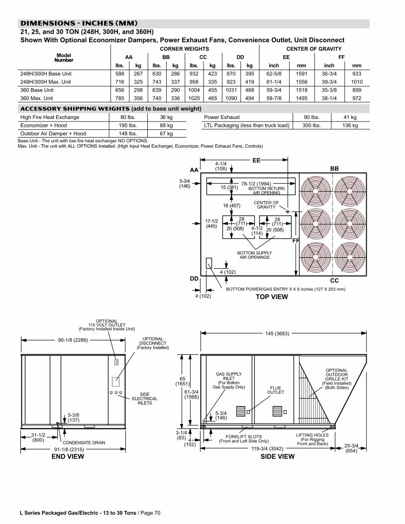
L Series Packaged Gas/Electric − 13 to 30 Tons / Page 70
DIMENSIONS − INCHES (MM)21, 25, and 30 TON (248H, 300H, and 360H)
Shown With Optional Economizer Dampers, Power Exhaust Fans, Convenience Outlet, Unit Disconnect
CORNER WEIGHTS CENTER OF GRAVITY
ModelNumber
AA BB CC DD EE FFNumber
lbs. kg lbs. kg lbs. kg lbs. kg inch mm inch mm
248H/300H Base Unit 588 267 630 286 932 423 870 395 62-5/8 1591 36-3/4 933
248H/300H Max. Unit 716 325 743 337 958 335 923 419 61-1/4 1556 39-3/4 1010
360 Base Unit 656 298 639 290 1004 455 1031 468 59-3/4 1518 35-3/8 899
360 Max. Unit 785 356 740 336 1025 465 1090 494 58-7/8 1495 38-1/4 972
ACCESSORY SHIPPING WEIGHTS (add to base unit weight)
High Fire Heat Exchange 80 lbs. 36 kg
Economizer + Hood 195 lbs. 88 kg
Outdoor Air Damper + Hood 148 lbs. 67 kg
Power Exhaust 90 lbs. 41 kg
LTL Packaging (less than truck load) 300 lbs. 136 kg
Base Unit − The unit with low fire heat exchanger NO OPTIONS.Max. Unit − The unit with ALL OPTIONS Installed. (High Input Heat Exchanger, Economizer, Power Exhaust Fans, Controls)
SIDE VIEW
TOP VIEW
END VIEW
FORKLIFT SLOTS(Front and Left Side Only)
90-1/8 (2289)
31-1/2(800)
91-1/8 (2315) 119−3/4 (3042)
145 (3683)
LIFTING HOLES(For Rigging
Front and Back)
BOTTOM POWER/GAS ENTRY 5 X 8 inches (127 X 203 mm)
BOTTOM SUPPLYAIR OPENINGS
BOTTOM RETURNAIR OPENING
4-1/4(108)
4-1/2(114)
28(711)
28(711)
4 (102)
4 (102)
5-3/4(146)
17-1/2(445)
20 (508) 20 (508)
15 (381)
18 (457)
78-1/2 (1994)
CONDENSATE DRAIN
5-3/8(137)
FLUEOUTLET
AA BB
CCDD
CENTER OFGRAVITY
EE
FF
25-3/4(654)
3-1/4(83)
61-3/4(1568)
GAS SUPPLYINLET
(For BottomGas Supply Only)
OPTIONALDISCONNECT
(Factory Installed)
OPTIONAL115 VOLT OUTLET
(Factory Installed Inside Unit)
SIDEELECTRICAL
INLETS
4(102)
5-3/4(146)
65(1651)
OPTIONALOUTDOORGRILLE KIT
(Field Installed)(Both Sides)
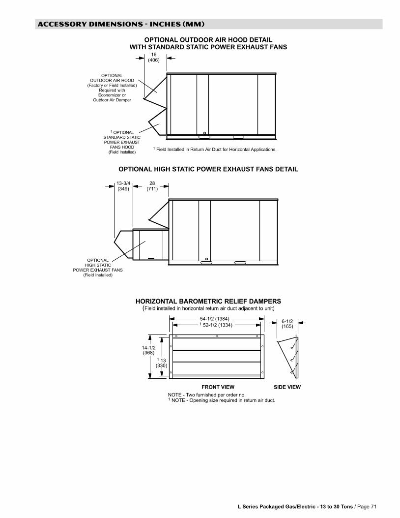
L Series Packaged Gas/Electric − 13 to 30 Tons / Page 71
ACCESSORY DIMENSIONS − INCHES (MM)
1 OPTIONALSTANDARD STATICPOWER EXHAUST
FANS HOOD(Field Installed)
OPTIONAL OUTDOOR AIR HOOD DETAILWITH STANDARD STATIC POWER EXHAUST FANS
16(406)
OPTIONALOUTDOOR AIR HOOD
(Factory or Field Installed)Required withEconomizer or
Outdoor Air Damper
1 Field Installed in Return Air Duct for Horizontal Applications.
OPTIONALHIGH STATIC
POWER EXHAUST FANS(Field Installed)
OPTIONAL HIGH STATIC POWER EXHAUST FANS DETAIL
28(711)
HORIZONTAL BAROMETRIC RELIEF DAMPERS(Field installed in horizontal return air duct adjacent to unit)
FRONT VIEW SIDE VIEW
54−1/2 (1384)
14-1/2(368)
1 13(330)
6-1/2(165)
1 52−1/2 (1334)
NOTE − Two furnished per order no. 1 NOTE − Opening size required in return air duct.
13−3/4(349)
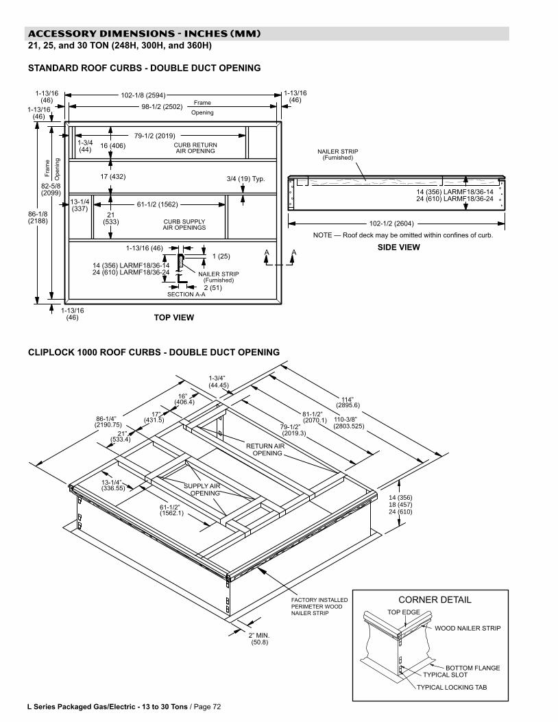
L Series Packaged Gas/Electric − 13 to 30 Tons / Page 72
ACCESSORY DIMENSIONS − INCHES (MM)21, 25, and 30 TON (248H, 300H, and 360H)
STANDARD ROOF CURBS − DOUBLE DUCT OPENING
1-3/4(44)
13-1/4(337)
1 (25)
2 (51)SECTION A-A
1-13/16 (46)
NOTE � Roof deck may be omitted within confines of curb.
SIDE VIEW
NAILER STRIP(Furnished)
14 (356) LARMF18/36-1424 (610) LARMF18/36-24
CURB SUPPLYAIR OPENINGS
TOP VIEW
Fra
me
Op
en
ing
Frame
Opening
17 (432)
21(533)
16 (406)
102-1/8 (2594)
79-1/2 (2019)
98-1/2 (2502)
86-1/8(2188)
82-5/8(2099)
102-1/2 (2604)
1-13/16(46)
AA
NAILER STRIP(Furnished)
14 (356) LARMF18/36-1424 (610) LARMF18/36-24
61-1/2 (1562)
1-13/16(46)
1-13/16(46)
1-13/16(46)
CURB RETURNAIR OPENING
3/4 (19) Typ.
CLIPLOCK 1000 ROOF CURBS − DOUBLE DUCT OPENING
TOP EDGE
BOTTOM FLANGE
TYPICAL LOCKING TAB
TYPICAL SLOT
WOOD NAILER STRIP
CORNER DETAILFACTORY INSTALLED
PERIMETER WOOD
NAILER STRIP
86−1/4"
114"
79−1/2"
OPENINGRETURN AIR
SUPPLY AIROPENING
(44.45)
110−3/8"
16"
17"
21"
13−1/4"
61−1/2"
81−1/2"
2" MIN.
(2190.75)
(533.4)
(431.5)
(406.4)
1−3/4"
(336.55)
(1562.1)
(50.8)
(2019.3)
(2070.1)(2803.525)
(2895.6)
14 (356)18 (457)24 (610)
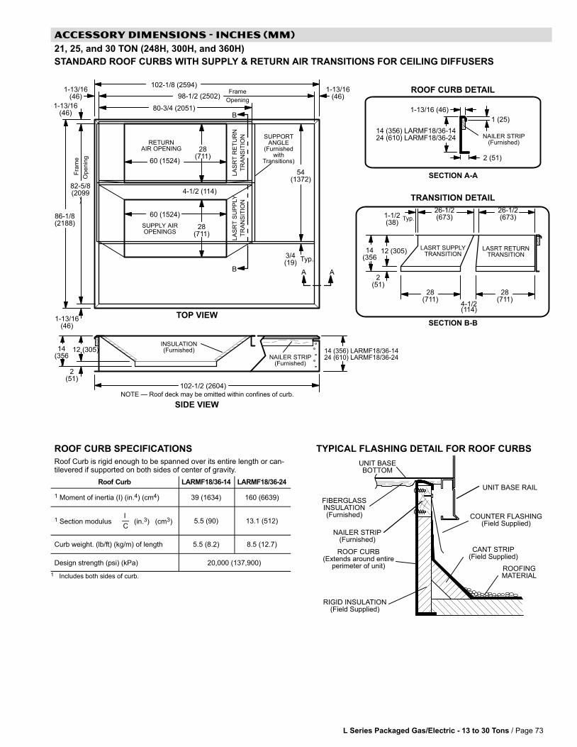
L Series Packaged Gas/Electric − 13 to 30 Tons / Page 73
ACCESSORY DIMENSIONS − INCHES (MM)
21, 25, and 30 TON (248H, 300H, and 360H)
STANDARD ROOF CURBS WITH SUPPLY & RETURN AIR TRANSITIONS FOR CEILING DIFFUSERS
LASRT RETURNTRANSITION
LASRT SUPPLYTRANSITION
SIDE VIEW
NAILER STRIP(Furnished)
RETURNAIR OPENING
SUPPLY AIROPENINGS
TOP VIEW
Fra
me
Op
en
ing
Frame
Opening
54(1372)
102-1/8 (2594)
98-1/2 (2502)
86-1/8(2188)
82-5/8(2099
)
102-1/2 (2604)
AA
3/4(19)
Typ.
4-1/2 (114)
SUPPORTANGLE
(Furnishedwith
Transitions)
INSULATION(Furnished)
2(51)
14(356
)
12 (305) 14 (356) LARMF18/36-1424 (610) LARMF18/36-24
NOTE � Roof deck may be omitted within confines of curb.
1-13/16(46)
TRANSITION DETAIL
80-3/4 (2051)
28(711)
60 (1524)
60 (1524)
B
B
SECTION B-B
26-1/2(673)
28(711)
28(711)
4-1/2(114)
28(711)
1 (25)
2 (51)
1-13/16 (46)
NAILER STRIP(Furnished)
14 (356) LARMF18/36-1424 (610) LARMF18/36-24
SECTION A-ALA
SR
T R
ET
UR
N
TR
AN
SIT
ION
LA
SR
T S
UP
PLY
TR
AN
SIT
ION
ROOF CURB DETAIL
14(356
)
2(51)
12 (305)
1-1/2(38)
Typ.
26-1/2(673)
1-13/16(46)
1-13/16(46)
1-13/16(46)
ROOF CURB SPECIFICATIONS
Roof Curb is rigid enough to be spanned over its entire length or can-tilevered if supported on both sides of center of gravity.
Roof Curb LARMF18/36-14 LARMF18/36-24
1 Moment of inertia (I) (in.4) (cm4) 39 (1634) 160 (6639)
1 Section modulusI�C
(in.3) (cm3) 5.5 (90) 13.1 (512)
Curb weight. (lb/ft) (kg/m) of length 5.5 (8.2) 8.5 (12.7)
Design strength (psi) (kPa) 20,000 (137,900)
1 Includes both sides of curb.
TYPICAL FLASHING DETAIL FOR ROOF CURBS
ROOF CURB(Extends around entire
perimeter of unit)
FIBERGLASSINSULATION(Furnished) COUNTER FLASHING
(Field Supplied)
UNIT BASEBOTTOM
RIGID INSULATION(Field Supplied)
ROOFINGMATERIAL
CANT STRIP(Field Supplied)
NAILER STRIP(Furnished)
UNIT BASE RAIL

L Series Packaged Gas/Electric − 13 to 30 Tons / Page 74
ACCESSORY DIMENSIONS − INCHES (MM)
21, 25, and 30 TON (248H, 300H, and 360H)
HORIZONTAL ROOF CURBS − Requires Optional Horizontal Return Air Panel Kit
1 LARMFH18/24-26 2 LARMFH18/24-37 3 LARMFH30/36-30 (used with 248H/300S/300H/360 Models) 4 LARMFH30/36-40 (used with 248H/300S/300H/360 Models)
102-1/8 (2594)
SIDE VIEW
TOP VIEW
Fra
me
Op
en
ing
Frame
Opening
54(1372)
98-1/2 (2502)
82-5/8(2099)
86-5/8 (2200)
98-1/2 (2502)
FRONT VIEW
NAILER STRIP(Furnished)
102-1/2 (2604)
CURB SUPPLYAIR OPENING
With 1-1/2 in. (38 mm) FLANGE
75 (1905)
5-1/2 (140)
SUPPLYDUCT
PANELS(Furnished)
SUPPLY AIRTURNING VANE
(Furnished)
1 (25)
2 (51)SECTION A-A
1-13/16 (46)
NAILER STRIP(Furnished)
AA
102-1/8 (2594) 86-1/4 (2191)
NOTE − Roof deck may be omitted within confines of curb.
SUPPLY AIRTURNING VANE
(Furnished)
PANEL TO COVER RETURN AIR OPENING IN BOTTOM OF UNIT(Furnished With Optional Horizontal Return Air Panel Kit)
SIDE VIEW(PACKAGED UNIT)
86-1/8(2188)
1-13/16 (46)
1-13/16(46)
1-13/16 (46)1-13/16 (46)
1,2 8-1/4 (210)3,4 13-1/4 (337)
1,3 6-1/2 (165)2,4 17-1/2 (445)
1 26 (660)2 37 (940)3 30 (762)4 41 (1041)
1,2 14 (356)3,4 18 (457)
1 26 (660)2 37 (940)3 30 (762)4 41 (1041)
NOTE LARMFH30/36-30 is designed for horizontaldischarge when unit is mounted on a slab.LARMFH30/36-41 is designed for horizontaldischarge when unit is mounted on a rooftop.
6-1/2 (165)LARMFH30/36-3017-1/2 (445)LARMFH30/36-41
1 NOTE − Top of Curb extends 4 inch (102mm) inside bottom of unit base. See TypicalFlashing Detail.
SIDE VIEW(Horizontal Openings)
HORIZONTAL ROOF CURB(Required For Horizontal Applications)
HORIZONTAL RETURNAIR OPENING
5-1/4(133)
15 (381)78-1/2 (1994)
65(1651)
HORIZONTALSUPPLY AIR OPENING
13-1/4(337)
75 (1905)18 (457)
2 (51)
1 26 (660)LARMFH30/36-301 37 (9401)LARMFH30/36-41
91 (2311)LARMFH30/36-30102 (2591)LARMFH30/36-41
OPTIONAL RETURN AIR PANEL KIT(Required For
Horizontal Applications
42-7/8(1089)
HORIZONTAL SUPPLY AND RETURN AIR OPENINGSROOFTOP UNIT WITH HORIZONTAL ROOF CURB
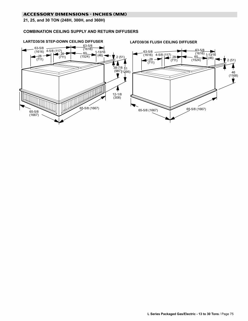
L Series Packaged Gas/Electric − 13 to 30 Tons / Page 75
ACCESSORY DIMENSIONS − INCHES (MM)
21, 25, and 30 TON (248H, 300H, and 360H)
COMBINATION CEILING SUPPLY AND RETURN DIFFUSERS
60(1524)
2 (51)2 (51)
LARTD30/36 STEP-DOWN CEILING DIFFUSER LAFD30/36 FLUSH CEILING DIFFUSER
63−5/8(1616)
28(711)
1−13/16(46)
60(1524)
63−5/8(1616)
65−5/8(1667)
12−1/8(308)
38−7/8(987)
51(1295)
28(711)
65−5/8 (1667)
46(1168)
65−5/8 (1667)
63−5/8(1616) 1−13/16
(46)28(711)
28(711)
65−5/8 (1667)
63−5/8(1616)
4−5/8 (117)
4−5/8 (117)

L Series Packaged Gas/Electric − 13 to 30 Tons / Page 76
GUIDE SPECIFICATIONS
This MANU−SPEC® utilizes the Construction Specifications Institute (CSI) Manual of Practice, includingMasterFormat�, SectionFormat� and PageFormat�. A MANU−SPEC is a manufacturer−specific proprietaryproduct specification using the proprietary method of specifying applicable to project specifications and masterguide specifications. Optional text is indicated by brackets [ ]; delete optional text in final copy of specification.Specifier Notes typically precede specification text; delete notes in final copy of specification. Trade/brand nameswith appropriate symbols typically are used in Specifier Notes; symbols are not used in specification
text. Metric conversion, where used, is soft metric conversion.
This MANU−SPEC specifies Lennox L Series® Rooftop Units. These products are manufactured by LennoxIndustries Inc. Revise MANU−SPEC section number and title below to suit project requirements, specificationpractices and section content. Refer to CSI MasterFormat for other section numbers and titles.
SECTION 15730
UNITARY AIR CONDITIONING EQUIPMENT
PART 1 GENERAL
PART 1.01 SUMMARY
A. Section Includes: Packaged rooftop units and commercial packaged, gas/electric and electric/electric heat pumps.
Specifier Note: Revise paragraph below to suit project requirements. Add section numbers and titles per CSI MasterFormat andspecifier’s practice.
B. Related Sections:
Specifier Note: Article below may be omitted when specifying manufacturer’s proprietary products and recommended installation.Retain Reference Article when specifying products and installation by an industry reference standard. If retained, list standard(s)referenced in this section. Indicate issuing authority name, acronym, standard designation and title. Establish policy for indicatingedition date of standard referenced. Conditions of the Contract or Division 1 References Section may establish the edition date ofstandards. This article does not require compliance with standard, but is merely a listing of references used. Article below should listonly those industry standards referenced in this section. Retain only those reference standards to be used within the text of thisSection. Add and delete as required for specific project.
PART 1.02 REFERENCES
A. American National Standards Institute (ANSI):
1. ANSI/ASHRAE 15 Safety Standard for Refrigeration Systems.
2. ANSI/ASHRAE/IESNA 90.1 Energy Efficient Design of New Buildings Except Low−Rise Residential Buildings.
3. ANSI Z21.47 Gas−Fired Central Furnaces.
B. Air−Conditioning and Refrigeration Institute (ARI):
1. ARI 210/240 Unitary Air−Conditioning and Air−Source Heat Pump Equipment.
2. ARI 270 Sound Rating of Outdoor Unitary Equipment.
3. ARI 340/360 Commercial and Industrial Unitary Air−Conditioning and Heat Pump Equipment.
4. ARI 370 Sound Rating of Large Outdoor Refrigerating and Air Conditioning Equipment.
C. American Society of Heating, Refrigerating, and Air−Conditioning Engineers, Inc. (ASHRAE):
1. ASHRAE 52.2 Method of Testing General Ventilation Air−Cleaning Devices for Removal Efficiency by Particle Size(ANSI approved).
2. ASHRAE 62.1 Ventilation for Acceptable Indoor Air Quality.
D. U.S. Energy Policy Act of 1992 (EPACT).
E. U.S. National Appliance Energy Conservation Act (NAECA):
1. NAECA 1988.
F. National Fire Protection Association (NFPA):
1. NFPA 90A Installation of Air Conditioning and Ventilation Systems.
G. Underwriters Laboratories, Inc. (UL):
1. UL 1995 Standard for Safety for Heating and Cooling Equipment.
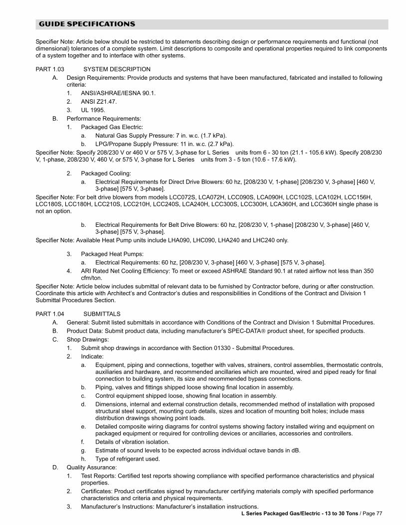
L Series Packaged Gas/Electric − 13 to 30 Tons / Page 77
GUIDE SPECIFICATIONS
Specifier Note: Article below should be restricted to statements describing design or performance requirements and functional (notdimensional) tolerances of a complete system. Limit descriptions to composite and operational properties required to link componentsof a system together and to interface with other systems.
PART 1.03 SYSTEM DESCRIPTION
A. Design Requirements: Provide products and systems that have been manufactured, fabricated and installed to followingcriteria:
1. ANSI/ASHRAE/IESNA 90.1.
2. ANSI Z21.47.
3. UL 1995.
B. Performance Requirements:
1. Packaged Gas Electric:
a. Natural Gas Supply Pressure: 7 in. w.c. (1.7 kPa).
b. LPG/Propane Supply Pressure: 11 in. w.c. (2.7 kPa).
Specifier Note: Specify 208/230 V or 460 V or 575 V, 3−phase for L Series® units from 6 − 30 ton (21.1 − 105.6 kW). Specify 208/230V, 1−phase, 208/230 V, 460 V, or 575 V, 3−phase for L Series® units from 3 − 5 ton (10.6 − 17.6 kW).
2. Packaged Cooling:
a. Electrical Requirements for Direct Drive Blowers: 60 hz, [208/230 V, 1−phase] [208/230 V, 3−phase] [460 V,3−phase] [575 V, 3−phase].
Specifier Note: For belt drive blowers from models LCC072S, LCA072H, LCC090S, LCA090H, LCC102S, LCA102H, LCC156H,LCC180S, LCC180H, LCC210S, LCC210H, LCC240S, LCA240H, LCC300S, LCC300H, LCA360H, and LCC360H single phase isnot an option.
b. Electrical Requirements for Belt Drive Blowers: 60 hz, [208/230 V, 1−phase] [208/230 V, 3−phase] [460 V,3−phase] [575 V, 3−phase].
Specifier Note: Available Heat Pump units include LHA090, LHC090, LHA240 and LHC240 only.
3. Packaged Heat Pumps:
a. Electrical Requirements: 60 hz, [208/230 V, 3−phase] [460 V, 3−phase] [575 V, 3−phase].
4. ARI Rated Net Cooling Efficiency: To meet or exceed ASHRAE Standard 90.1 at rated airflow not less than 350cfm/ton.
Specifier Note: Article below includes submittal of relevant data to be furnished by Contractor before, during or after construction.Coordinate this article with Architect’s and Contractor’s duties and responsibilities in Conditions of the Contract and Division 1Submittal Procedures Section.
PART 1.04 SUBMITTALS
A. General: Submit listed submittals in accordance with Conditions of the Contract and Division 1 Submittal Procedures.
B. Product Data: Submit product data, including manufacturer’s SPEC−DATA® product sheet, for specified products.
C. Shop Drawings:
1. Submit shop drawings in accordance with Section 01330 − Submittal Procedures.
2. Indicate:
a. Equipment, piping and connections, together with valves, strainers, control assemblies, thermostatic controls,auxiliaries and hardware, and recommended ancillaries which are mounted, wired and piped ready for finalconnection to building system, its size and recommended bypass connections.
b. Piping, valves and fittings shipped loose showing final location in assembly.
c. Control equipment shipped loose, showing final location in assembly.
d. Dimensions, internal and external construction details, recommended method of installation with proposedstructural steel support, mounting curb details, sizes and location of mounting bolt holes; include massdistribution drawings showing point loads.
e. Detailed composite wiring diagrams for control systems showing factory installed wiring and equipment onpackaged equipment or required for controlling devices or ancillaries, accessories and controllers.
f. Details of vibration isolation.
g. Estimate of sound levels to be expected across individual octave bands in dB.
h. Type of refrigerant used.
D. Quality Assurance:
1. Test Reports: Certified test reports showing compliance with specified performance characteristics and physicalproperties.
2. Certificates: Product certificates signed by manufacturer certifying materials comply with specified performancecharacteristics and criteria and physical requirements.
3. Manufacturer’s Instructions: Manufacturer’s installation instructions.
L Series Packaged Gas/Electric − 13 to 30 Tons / Page 78
GUIDE SPECIFICATIONS
Specifier Note: Coordinate paragraph below with Part 3 Field Quality Requirements Article herein. Retain or delete as applicable.
E. Manufacturer’s Field Reports: Manufacturer’s field reports specified.
F. Closeout Submittals: Submit the following:
1. Warranty: Warranty documents specified.
2. Operation and Maintenance Data: Operation and maintenance data for installed products in accordance with Division 1 Closeout Submittals (Maintenance Data and Operation Data) Section. Include methods for maintaininginstalled products and precautions against cleaning materials and methods detrimental to finishes and performance.Include names and addresses of spare part suppliers.
3. Provide brief description of unit, with details of function, operation, control and component service.
4. Commissioning Report: Submit commissioning reports, report forms and schematics in accordance with Section 01810 − Commissioning.
PART 1.05 QUALITY ASSURANCE
A. Qualifications:
1. Installer experienced in performing work of this section who has specialized in installation of work similar to thatrequired for this project.
2. Manufacturer Qualifications: Manufacturer capable of providing field service representation during construction andapproving application method.
Specifier Note: Paragraph below should list obligations for compliance with specific code requirements particular to this section.General statements to comply with a particular code are typically addressed in Conditions of the Contract and Division 1 RegulatoryRequirements Section. Repetitive statements should be avoided. Current data on building code requirements and product compliancemay be obtained from filter manufacturer technical support specialists.
B. Regulatory Requirements: Provide [Packaged gas electric] [Packaged cooling] [Packaged heat pump] that complies withthe following requirements:
1. ARI 210/240.
2. ARI 270.
3. ARI 340/360.
4. ASHRAE 52.2.
5. NFPA 90A.
C. Preinstallation Meetings: Conduct preinstallation meeting to verify project requirements, manufacturer’s installationinstructions and manufacturer’s warranty requirements. Comply with Division 1 Project Management and Coordination(Project Meetings).
PART 1.06 DELIVERY, STORAGE & HANDLING
A. General: Comply with Division 1 Product Requirements.
B. Ordering: Comply with manufacturer’s ordering instructions and lead time requirements to avoid construction delays.
C. Packing, Shipping, Handling and Delivery:
1. Deliver materials in manufacturer’s original, unopened, undamaged containers with identification labels intact.
2. Ship, handle and unload units according to manufacturer’s instructions.
D. Storage and Protection:
1. Store materials protected from exposure to harmful weather conditions.
2. Factory shipping covers to remain in place until installation.
PART 1.07 PROJECT CONDITIONS
A. Installation Location: [Confirm design conditions and temperature.].
Specifier Note: Coordinate article below with Conditions of the Contract and with Division 1 Closeout Submittals (Warranty).
PART 1.08 WARRANTY
A. Project Warranty: Refer to Conditions of the Contract for project warranty provisions.
B. Manufacturer’s Warranty: Submit, for Owner’s acceptance, manufacturer’s standard warranty document executed byauthorized company official. Manufacturer’s warranty is in addition to, and not a limitation of, other rights Owner may haveunder Contract Documents.
L Series Packaged Gas/Electric − 13 to 30 Tons / Page 79
GUIDE SPECIFICATIONS
Specifier Note: Coordinate paragraph below with manufacturer’s warranty requirements.
C. Warranty: Commencing on Date of Installation.
1. Compressors: 5 years (limited).
2. Integrated Modular Control: 3 years (limited).
3. Other System Components: 1 year (limited).
4. Aluminized Heat Exchangers: 10 years (limited).
5. Stainless Steel Heat Exchangers: 15 years (limited).
PART 2 PRODUCTS
Specifier Note: Retain article below for proprietary method specification. Add product attributes, performance characteristics, materialstandards and descriptions as applicable. Use of such phrases as �or equal" or �or approved equal" or similar phrases may causeambiguity in specifications. Such phrases require verification (procedural, legal and regulatory) and assignment of responsibility fordetermining �or equal" products.
PART 2.01 ROOFTOP UNITS
A. Manufacturer: Lennox Industries Inc.
1. Contact: 2100 Lake Park Blvd., Richardson, TX 75080; Telephone: (800) 453−6669; website: www.lennox.com.
B. Proprietary Products/Systems: Lennox L Series® Unitary Air Conditioning Equipment, including the following equipment:
1. Cabinet: Weatherproofing tested and certified to AGA [Rain test standards] and soundproofing tested to ARI 270,dbA at [______] y (______) y (______) m free field.
a. Heavy gauge steel panels and full perimeter heavy gauge galvanized steel base rails.
b. Raised edges around duct and power entry openings in bottom of unit.
c. Airflow Configuration: [Down−flow (vertical) return air] [Horizontal return airflow with Horizontal Roof MountingFrame] [And Horizontal Return Air Panel Kit (required when converting down−flow configured unit to horizontalairflow)].
d. Power Entry: Electrical [And gas] lines brought through unit base or through horizontal access knockouts.
e. Exterior Panels: Constructed of heavy gauge, galvanized steel with 2−layer enamel paint finish.
f. Insulation: All panels adjacent to conditioned air fully insulated with non−hygroscopic fiberglass insulation. Unitbase fully insulated.
g. Base Rail: Full perimeter base rail with rigging holes; 3 sides with fork slots.
h. Access Panels: Hinged for compressor/controls/heating areas, blower access and air filter/economizer access;and, sealed with quarter−turn latching handles and tight air and water seal.
2. Compressor:
a. Copeland scroll� type, hermetically sealed.
3. Fans, General: Centrifugal, forward curved impellers, statically and dynamically balanced. [Multi] V−belt drive withadjustable variable pitch motor pulley.
a. Condenser Fan: Low sound operating, PVC coated fan guard, direct drive propeller type fans to dischargevertically.
b. Condenser Fan Motor: Permanently lubricated, permanent split capacitor; totally enclosed from weather, dustand corrosion; permanently lubricated ball bearings; resiliently mounted; overload protected.
4. Evaporator Coils: Pressure and leak tested to 500 psi (3445 kPa), nonferrous coils with enhanced aluminum finsmechanically bonded to durable copper tubes.
5. Condenser Coils:
a. Pressure and leak tested to 500 psi (3445 kPa), nonferrous coils with enhanced aluminum fins mechanicallybonded to durable copper tubes.
Specifier Note: Specify slab construction for L Series® over 6 tons (21.1 kW), excluding heat pumps.
b. [Formed construction] [Slab construction].
6. Air Distribution:
a. Equipment capable of down−flow (vertical) or side (horizontal) handling of conditioned air.
b. Optional Equipment:

L Series Packaged Gas/Electric − 13 to 30 Tons / Page 80
GUIDE SPECIFICATIONS
Specifier Note: The following kit is required for horizontal air handling for L Series® 3 − 12 ton (10.6 − 42.2 kW) models.
1) Horizontal conversion kit for horizontal air handling.
Specifier Note: The following kit is required for horizontal air handling for L Series®, 13 − 30 ton (45.8 − 105.6 kW) models.
2) Horizontal return air panel kit and horizontal roof mounting frame for horizontal air handling.
7. Filters: To meet NFPA 90A, air filter requirements [Type Class 1] [Type Class 2]; [______]% efficiency, metal framed,[Replaceable media] [Throwaway] [Standard to unit manufacturer].
a. Disposable 2 inch (51 mm) pleated MERV 7 rated.
b. Disposable 2 inch (51 mm) pleated MERV 11 rated.
8. Heat Exchanger: Removable for servicing; stainless steel optional for applications where mixed air temperaturebelow 45 degrees F (7 degrees C); E.T.L./C.S.A. design certified for outdoor installation.
9. Gas Heating System:
a. Tubular heat exchanger and inshot type gas burners constructed of aluminized steel.
b. Direct spark ignition; electronic flame sensor controls; flame rollout switch; limit controls and automaticredundant dual gas valve with staging control and combustion air proving switch on combustion air inducer.
Specifier Note: When LPG/propane is required, specify optional kit.
c. Able to use LPG/propane [With optional kit].
d. Complete service access provided for controls and wiring.
10. Electric Heating System:
a. Available for factory or field installation.
b. Heating elements of Nichrome bare wire exposed directly to airstream.
11. Refrigeration System:
a. Self−sealing, discharge, suction and liquid line service gauge ports, freeze−stats, expansion valves and fullrefrigerant charge.
b. Copper tubing not to touch sharp metal surfaces.
c. Compressor Circuits: Automatic reset, high pressure switch; automatic reset, low pressure switch; liquid linefilter−drier.
Cooling system capable of operating down to 0 deg. F outdoortemperature as shipped from the factory.
d. Capable of operating down to 0 degrees F (−17 degrees C) without installation of additional controls.
12. Supply Air Blower:
a. [Constant air volume with adjustable pulleys] [Variable air volume with fixed pulleys and variable frequencydrive] [Variable air volume with fixed pulleys and variable frequency drive with bypass].
b. Centrifugal supply air blower with [Permanently lubricated ball bearings and adjustable belt drive] [Sleevebearings and multi−speed direct drive motor].
c. Blower assembly [Slides out of unit] [Is accessible] for servicing.
d. Blower wheel statically and dynamically balanced.
13. Integrated Modular Control (IMC):
a. Solid−state control board to operate unit.
b. Built−in functions include: blower on/off delay; built−in control parameter defaults; service relay output; dirty filterswitch input; dehumidistat input, economizer control; [Gas valve delay between stages]; [ETM compatible];[DDC compatible]; unit diagnosis; diagnostics code storage; indoor air quality input; low ambient controls;minimum run time; night setback mode; smoke alarm mode; low pressure control; thermostat bounce delay;3−digit display; degrees F or degrees C display, 2−stage heat/3−stage cool thermostat compatible and warm−upmode; [Electric heat staging].
L Series Packaged Gas/Electric − 13 to 30 Tons / Page 81
GUIDE SPECIFICATIONS
14. Gas Heating Controls:
a. Remote thermostat[s] as indicated.
b. Built−in [Un] fused disconnect switch.
c. Two stages of heating control from [Thermostat] [DDC].
d. Supply fan to turn on [40] seconds after heating demand is received with 8 − 60 second adjustable time delay.
e. Supply fan to turn off [120] seconds after heating demand has ended with 80 − 300 second adjustable timedelay.
f. Adjustable delay time of [30] [Value between 30 − 160] seconds between low and high fire of 2−stage gas valvesystem.
g. Heat off delay of [100] [Value between 30 − 300] seconds after thermostat heating demand has ended.
h. To turn off heat and keep supply air fan running if overheat limit occurs.
i. Adjustable maximum overheat limit trip count during heating cycle of [3] [Value between 1 − 15], with digitaloutput, limit indicator.
j. To report error with each occurrence of overheat limit trip and to identify limit that tripped. Error code stored innonvolatile memory.
k. To shut off gas heat if flame rollout occurs and to report error identifying rollout switch.
l. Maximum flame rollout switch trip count of [3] during heating cycle, with digital output, limit indicator. Maximumcount limit adjustable from 1 − 6 counts.
m. To turn off heat if induced airflow is too low and to report error identifying pressure switch.
n. Maximum induced airflow pressure switch trip count of [3] during heating cycle, with digital output, limitindicator. Maximum count limit adjustable from 1 − 6 counts.
o. Error reported if gas valve not energized 2 minutes after heating demand; gas valve identified.
p. Maximum ignition failure count of [3] with digital output, limit indicator. Maximum count limit adjustable from 1 −6 counts.
q. To shut off gas valve if flame not sensed. Error reported and stored in nonvolatile memory.
r. Delay between stages on gas valve.
s. To shut off unit if gas valve is energized with no demand for heat. Error reported and stored in nonvolatilememory.
15. Electric Heating Controls:
a. Panel board with [______] stage controller.
b. Remote thermostat[s] as indicated.
c. Built−in [Un] fused disconnect switch.
d. Supply Fan: Start before electric elements are energized and continue operating until bonnet temperaturereaches minimum setting. Include switch for continuous fan operation.
e. Two stages of heating control from [Thermostat] [DDC].
f. Supply fan to turn off [20] seconds after heating demand has ended. Time delay adjustable from 0 − 300seconds.
g. With delay time of [12] seconds between low and high heat stages. Time delay adjustable from 12 − 60seconds.
h. To turn off heat and keep supply air fan running if overheat limit occurs.
i. Adjustable maximum overheat limit trip count of [3] during heating cycle with digital output, limit indicator.Maximum count limit adjustable from 1 − 15 counts.
j. Error reported and identified if overheat limit tripped. Error code stored in nonvolatile memory.
16. Cooling Controls:
a. Provide [Smoke detectors in return] [Smoke detectors in supply].
L Series Packaged Gas/Electric − 13 to 30 Tons / Page 82
GUIDE SPECIFICATIONS
Specifier Note: Specify b, c or d below.
b. [Manual] [Automatic] outside [And return] air dampers for fixed outside air quantity.
c. Remote controlled outside [And return] air dampers with damper operator and means for adjusting outside airquantity.
d. Motorized outside, return and [Automatic] [Power exhaust] [Gravity] relief dampers with spring return damperoperator and control package to automatically vary outside air quantity. Outside air and exhaust air dampers,normally closed.
e. Tight−fitting parallel blade dampers with neoprene or suitable gaskets, synthetic bushings and 1% maximumleakage.
f. Damper Operation: 24 V, spring return motor with gear train sealed in oil.
g. Mixed Air Controls: [Maintain 55 degrees F (13 degrees C)] [Indicated] mixed air temperature (adjustable).
h. Up to 2 stages of cooling from [Thermostat] [External DDC controller] without need for additional controls.
i. Up to 3 stages of cooling when used with relay and [3−stage thermostat] [DDC controller].
Specifier Note: Specify article �j" when used with Lennox L Connection Network Building Automation System.
j. Up to 4 stages of cooling.
k. To allow blower on delay of up to 60 seconds after cooling demand is received. Default value of zero.
l. To allow blower off delay of up to 240 seconds after cooling demand has ended. Default value of zero.
m. Minimum compressor on time of [240] seconds on 3−phase units, adjustable between 60 − 510 seconds.
n. Minimum compressor off time of [300] seconds on single−phase units, adjustable from 60 − 510 seconds.
o. Default maximum high pressure switch trip occurrence during cooling or dehumidification cycle of [3]. Tripoccurrence limit adjustable from 1 − 8 occurrences. If maximum limit reached, compressor locked out anddigital output for service activated.
p. Default maximum low pressure switch trip occurrence during cooling or dehumidification cycle of [3]. Tripoccurrence limit adjustable from 1 − 8 occurrences. If maximum limit reached, compressor locked out anddigital output for service activated.
q. Low pressure trip read delay of [5] minutes if compressor off time has been less than 4 hours and outdoortemperature is less than 70 degrees F (21 degrees C). Delay adjustable from 0 − 34 minutes. Temperature setpoint adjustable from 10 degrees F (−12 degrees C) to 100 degrees F (38 degrees C). Compressor off timeadjustable from 1 − 6 hours.
r. Low pressure trip read delay of [15] minutes if compressor off time has been 4 hours or greater and outdoortemperature is less than 70 degrees F (21 degrees C). Delay adjustable from 0 − 34 minutes. Temperature setpoint adjustable from 10 degrees F (−12 degrees C) to 100 degrees F (38 degrees C). Compressor off timeadjustable from 1 − 6 hours.
s. Low pressure trip read delay of [2] minutes if compressor off time has been less than 4 hours and outdoortemperature is 70 degrees F (21 degrees C) or greater. Delay adjustable from 0 − 34 minutes.
t. Temperature set point adjustable from 10 degrees F (−12 degrees C) to 100 degrees F (38 degrees C).Compressor off time adjustable from 1 − 6 hours.
u. Low pressure trip read delay of [8] minutes if compressor off time has been 4 hours or greater and outdoortemperature is 70 degrees F (21 degrees C) or greater. Delay adjustable from 0 − 34 minutes.
v. Temperature set point adjustable from 10 degrees F (−12 degrees C) to 100 degrees F (38 degrees C).Compressor off time adjustable from 1 − 6 hours.
w. Each pressure switch trip occurrence (either high or low) to record error in nonvolatile memory and identifycompressor circuit.
x. Low outdoor air temperature compressor lockout set point of 0 degrees F (−18 degrees C) for each compressorcircuit. Low outdoor temperature limit set point individually adjustable for each compressor circuit from 80degrees F (27 degrees C) to −30 degrees F (−34 degrees C).
y. Maximum allowable evaporator freeze−stat trip occurrence of [3] during cooling demand with limit adjustablefrom 1 − 4 occurrences. Control to shut off compressor each time freeze−stat trip occurs and record error codein nonvolatile memory. If maximum limit reached, compressor locked out and digital output for serviceactivated.
z. Condenser Fan Control:
1) On units with multiple condenser fans, [6] second time delay between condenser fan shutoff and restartto prevent reverse rotation of fan. Time delay adjustable between 0 − 16 seconds.
2) On units with 4 condenser fans, first stage low outdoor temperature set point of 55 degrees F (13 degreesC) that reduces airflow through condenser by turning off some fans. Set point adjustable between 60degrees F (16 degrees C) and 10 degrees F (−12 degrees C).
3) On units with 6 condenser fans, second stage low outdoor temperature set point of 40 degrees F (4degrees C) to reduce airflow through condenser by turning off all fans. Set point adjustable between 60degrees F (16 degrees C) and 10 degrees F (−12 degrees C).
4) On units with 6 condenser fans, condenser fan on delay of [2] seconds. Adjustable between 0 − 240seconds.
L Series Packaged Gas/Electric − 13 to 30 Tons / Page 83
GUIDE SPECIFICATIONS
Specifier Note: Edit article below to suit project requirements. If substitutions are permitted, edit text below. Add text to refer to Division 1 Project Requirements (Product Substitutions Procedures) Section.
PART 2.02 PRODUCT SUBSTITUTIONS
A. Substitutions: No substitutions permitted.
PART 3 EXECUTION
PART 3.01 MANUFACTURER’S INSTRUCTIONS
Specifier Note: Article below is an addition to the CSI SectionFormat and a supplement to MANU−SPEC. Revise article below to suitproject requirements and specifier’s practice.
A. Compliance: Comply with manufacturer’s written data, including product technical bulletins, product catalog installationinstructions, product carton installation instructions and manufacturer SPEC−DATA® sheets.
PART 3.02 EXAMINATION
A. Site Verification of Conditions: Verify substrate conditions, which have been previously installed under other sections, areacceptable for product installation in accordance with manufacturer’s instructions.
PART 3.03 INSTALLATION
A. Install [Packaged rooftop units] [And] [Commercial packaged, gas/electric and electric/electric heat pumps] in accordancewith manufacturer’s instructions, on roof curbs [Provided by manufacturer] [As indicated].
B. Run drain line from cooling coil condensation drain pan to discharge [Over roof drain].
PART 3.04 FIELD QUALITY CONTROL
Specifier Note: Use the following Articles only when manufacturer’s field services are desired to verify the quality of the installedcomponents. Establish the number and duration of periodic site visits required by Manufacturer and specify below. ConsultManufacturer for services required. Delete if field services are not required.
A. Have manufacturer of products supplied under this Section review Work involved in handling, installation/application,protection and cleaning of its product[s], and submit written reports in acceptable format to verify compliance of Work withContract.
B. Manufacturer’s Field Services: Provide manufacturer’s field services consisting of product use recommendations andperiodic site visits for inspection of product installation in accordance with manufacturer’s instructions.
C. Schedule site visits to review Work at stages listed:
1. After delivery and storage of products, and when preparatory Work on which Work of this Section depends iscomplete, but before installation begins.
2. [Twice] during progress of Work at [25%] and [60%] complete.
3. Upon completion of Work, after cleaning is carried out.
D. Obtain reports within [3] days of review and submit.
L Series Packaged Gas/Electric − 13 to 30 Tons / Page 84
GUIDE SPECIFICATIONS
PART 3.05 PERFORMANCE VERIFICATION
Specifier Note: Commissioning must ensure performance verification of every part of the unit including, but not necessarily limited to,the following components, as a factory−built and packaged unit: (a) mixing chamber or plenum with outside air and return air dampers;filters; either (i) heating coil or (ii) gas−fired heating unit; DX refrigeration system (generally with air−cooled condenser DX cooling coilwith drain pan); humidifier; supply fan with motor and drive; exhaust air dampers; weatherproof curbs [Incorporating vibrationisolators].
A. General:
1. Perform rooftop air handling unit verification in accordance with Section 01750 Starting and Adjusting supplementedas follows:
2. Settings:
a. Set outside air and return air dampers for minimum outside air.
b. Set outside air and return air dampers for percentage of outside air required by design and repeatmeasurements of fan capacity.
3. Measurements:
a. Measure supply fan capacity.
b. Measure pressure drop of each component of air handling unit.
c. Measure DBT, WBT of SA, RA, EA.
d. Measure air cooled condenser discharge DBT.
e. Measure flow rates (minimum and maximum) of SA, RA, EA.
f. Measure radiated and discharge sound power levels under maximum heating demand and under maximumcooling demand with compressors running.
g. Measure DX refrigeration system performance as specified.
4. Simulations:
a. Simulate maximum cooling load and measure refrigerant hot gas and suction temperatures and pressures.
b. Simulate maximum heating load and:
1) Verify temperature rise across heat exchanger.
2) Perform flue gas analysis.
3) Verify combustion airflow to heat exchanger.
4) Simulate minimum heating load and repeat measurements.
5. Control Strategies:
a. Verify operating control strategies, including:
1) Heat exchanger operating and high limit.
2) Early morning warm−up cycle.
3) Freeze protection.
4) cycle operation, temperature of changeover.
5) Alarms.
6) Voltage drop across thermostat wiring.
7) Operation of remote panel, including pilot lights, failure modes.
6. Operation and Adjustment:
a. Check for smooth, vibrationless correct rotation of supply fan impeller.
b. Adjust impeller speed as necessary and repeat measurement of fan capacity.
c. Reduce differences between fan capacity at minimum and maximum outside air less than [5]%.
d. Reduce difference between fan capacity at full cooling and fan capacity at full heating to less than [5]%.
e. OAD: Verify for proper travel.
f. Use smoke test to verify no short−circuiting of EA, relief air to outside air intake.
g. Check for smooth, vibrationless, correct rotation of power exhaust impeller.
h. Check capacity of heating unit.
i. Refer to other sections of these specifications for PV procedures for other components.
PART 3.06 COMPLETION AND CLEANUP
A. Upon completion and verification of performance of installation, remove surplus materials, excess materials, rubbish, toolsand equipment.
END OF SECTION
SG − Packaged Gas / Electric − 40 Ton / Page 85
APPLICATION GUIDE CONTROLS IMC M1−7
AFTERMARKET ZONING SYSTEM INTERFACE
Introduction
Lennox’ seventh generation premium rooftop unit (RTU) controller, the Integrated Modular Controller (IMC) version M1−7,
along with a variable frequency drive (VFD) option on certain L Series® and S−Class� RTUs, increases the ability of premium
Lennox RTUs to be applied to a variety of zoning systems. The type of zoning system to be used dictates the type of RTU and
the requirements for the zoning control system. The following explains each basic system and how the IMC must interface
with an aftermarket zoning control system to meet the requirements of each application.
Lennox units in single zone and constant volume bypass applications may utilize an aftermarket unit controller as
supervisory controller for the RTU. The IMC runs in thermostat mode and is primarily useful for diagnostic purposes, allowing
the aftermarket controller to directly monitor and control heat/cool staging, the bypass damper, zone dampers, economizer
damper, etc. When the IMC is used in thermostat mode, a maximum of two stage heating and three stage cooling are
available. An optional Four Stage Control (FS1) board may be added to allow four stages of heating and cooling control.
Supervisory control must be provided by the Lennox IMC to minimize complication and standardize control on Lennox
VFD−controlled variable air volume (VAV) RTUs. In this configuration, the IMC controls the VFD based on static pressure in
the supply duct. It controls the economizer, and stages compressors based on discharge air temperature. The aftermarket
controller simply sends calls for cooling or heating based on setpoint and schedule conditions. The IMC also has many
options for controlling single−stage, 50% power exhaust fans; two−stage, 100% Power exhaust fans; or modulating power
exhaust fans.
NOTE − Please refer to the IMC Manual (M1−7 Version 5.0x) for additional details.
Interface Definition
With a aftermarket control system interface, the IMC requires four digital inputs to control the rooftop unit: G (blower enable),
OCP (occupied), Y1 (enables discharge cooling), and W1 (enables discharge heating).
This application minimizes the controls expertise required to create a viable interface. Further, it creates a consistent,
standardized approach conducive to support and trouble−shooting on a broad basis without the need for substantial
knowledge of the IMC, VFD, bypass, or aftermarket controllers or systems.

SG − Package Gas / Electric − 40 Ton / Page 86
APPLICATION GUIDE CONTROLS IMC M1−7
AFTERMARKET ZONING SYSTEM INTERFACE
Constant Volume Bypass RTU Wiring Summary(Aftermarket Supervisory Control)
Heating Demand
Cooling Demand
Occupied Demand
Ventilation Demand
Supply StaticrPres. Senso
L Series / S-Class RTUTB1
G
OCP
Y1
W1
C
AftermarketRTU Controller
TB18Common
Optional BuildingStatic Pres. Switch orSensor
24VAC Digital Signals
Bypass Damper2-10V, 2V FullOpen
w/M1-6 or M1-7 IMC
Variable Air Volume RTU Wiring Summary(IMC Supervisory Control)
L Series / S-Class RTU
TB18
Optional BuildingStatic Pres. Switch orSensor
Supply StaticrPres. Senso
Heating Demand
Cooling Demand
Occupied Demand
Ventilation Demand
TB1
G
OCP
Y1
W1
C
24VAC Digital Signals
AftermarketRTU Controller
Common
VariableFrequency Drive2-10V, 10V FullOpen (or BypassDamper as
)Shown Above
w/ M1-7 IMC
SG − Packaged Gas / Electric − 40 Ton / Page 87
APPLICATION GUIDE CONTROLS IMC M1−7
AFTERMARKET ZONING SYSTEM INTERFACE
Sequence of OperationIMC Supervisory Control
Operation when IMC blower (G) input is energized
When a G signal is present, the IMC controls the VFD or bypass damper to hold a constant supply duct static
pressure based on the input from the IMC pressure sensor using a PID control loop. For increased flexibility,
the IMC has separate adjustable static pressure setpoints for ventilation, cooling, heating and smoke
alarms. These set points reside in the memory of the IMC, have factory default settings, and may be
adjusted in the field prior to start up.
Operation when IMC occupied (OCP) input is energized
When an OCP signal is present the IMC adjusts the fresh air damper to either a fixed minimum position or
allows it to modulate based on a CO2 sensor. The CO2 sensor can be wired directly to the IMC, to another
controller that can monitor the sensor and pass a signal to the IMC for damper control, or to both the IMC and
another device for monitoring through the desired man−machine interface while the IMC maintains damper
control. During morning warm−up/cool−down the IMC keeps the fresh air damper closed based on the IMC
configuration settings selected. The set points for minimum and maximum damper position setting and CO2
control reside in the memory of the IMC, have factory default settings, and may be adjusted at start up. They
cannot be adjusted using the aftermarket controls system.
Operation when IMC first stage cooling (Y1) input is energized
When a Y1 signal is present the IMC controls up to 4 stages of cooling (depending on RTU size) to maintain a
cooling discharge air temperature setpoint. These stages include mechanical cooling, or outdoor air for
cooling with an economizer. The discharge air temperature setpoint resides in the IMC, has a factory default
setting, and may be adjusted at start up. It cannot be adjusted using the aftermarket controls system. The
IMC has advanced discharge−air cooling reset options selected at start up based on return air temperature
and/or outside air temperature. Outside air reset saves energy by gradually increasing the discharge air set
point as outside air temperature decreases. Return air reset reduces potential for overcooling if the zoning
system is misapplied or has an abnormal condition or dominant zone. The reset gradually increases
discharge air temperature as return air temperature decreases.
Operation when IMC first stage heating (W1) input is energized
When a W1 signal is present, the IMC controls up to 4 stages of heating (depending on RTU size) to maintain
a heating discharge air temperature. The heating discharge air temperature set point resides in the IMC, has
a factory default setting, and may be adjusted at start up. It cannot be adjusted using the aftermarket controls
system. The IMC has advanced discharge air heating reset options based on return air temperature and/or
outside air temperature. Outside air reset saves energy by gradually decreasing the discharge air set point
as outside air temperature increases. Return air reset reduces possibility of overheating if the zoning system
is misapplied, has an abnormal condition or dominant zone. The reset gradually decreases discharge air
temperature as return air temperature decreases.
Power Exhaust Fan Operation
The IMC has many power exhaust fan control options that include single−stage, two−stage and modulating
control depending on how the unit is equipped. Stage control options can be triggered based on fresh air
damper positions, pressure switches, or a pressure analog sensor. Modulating control for units with VFD
powered exhaust fans are typically modulated to maintain return or building static pressure, but can be
staged. Set points and operation settings for controlling power exhaust fans reside in the IMC, have factory
default settings, and may be adjusted at start up. They cannot be adjusted using the aftermarket controls
system.

Visit us at www.lennox.com
For the latest technical information, www.lennoxdavenet.com
Contact us at 1−800−4−LENNOX