leveraging bim for cfd modeling -...
TRANSCRIPT

Leveraging BIM for CFD Modeling Aryn Bergman, P.E. – Energy Analyst @ TL Circle 3D Modeling, BIM Manager @ Facebook
MP3397-P
For high performance HVAC systems such as radiant heating and cooling, UFAD, natural ventilation and hybrid systems utilizing both natural and mechanical conditioning of a building, it is critical to understand how the air flows and the surrounding environment impacts the occupants comfort while still being able to balance energy savings. Computational Fluid Dynamics (CFD) models are key to understanding this balance. This class will teach you how to prepare an Autodesk Revit 2013 model and import into Autodesk Simulation CFD to quickly create wind driven models of the airflow around the exterior of a building as well as buoyancy driven transient models to understand the impacts of the building thermal mass and temperature. You will leave the presentation with skills to use your CFD model to optimize your building and achieve energy savings for your high performance HVAC system.
LearningObjectives
At the end of this class, you will be able to:
Create the correct BIM geometry and properly import BIM to CFD Simulation CFD 360.
Quickly perform wind driven analysis.
Create buoyancy driven models to understand thermal mass and temperature.
Understand CFD model results to optimize your building and energy savings.

Creating BIM Models for Energy Analysis
2
AbouttheSpeakers
Aryn graduated from North Carolina State University with a B.S. in Mechanical Engineering and spent the first 5 years of his career in the building industry as an Energy Analyst and an HVAC Design Engineer at the San Francisco office of Glumac, an MEP engineering consulting firm. He then spent the past 3 years as a Subject Matter Expert at Autodesk focusing on Green Building Studio and Revit MEP but he also works with Ecotect 2011 and Autodesk Simulation CFD. Now he is an independent energy analyst and HVAC design engineer through TL Circle. He provides energy audits and retro-commissioning services along with BIM models for HVAC design.
He has recently joined Facebook as a BIM Manager to help with their transition over to using Revit for their datacenter designs.
While not working, Aryn likes to volunteer in rebuilding efforts in developing areas like Haiti and South Sudan. He’s big into mountain biking, snowboarding, and Krav Maga.
[email protected] ; [email protected]
Jun Ortega has been a Technical Specialist with the Simulation Team at Autodesk since 2011. Jun joined Autodesk with the acquisition of Blue Ridge Numerics (CFdesign). Jun was in a similar role with Blue Ridge Numerics for 8 years. As a Technical Specialist, Jun supports technical sales through customer-facing engagements, works with the Autodesk partner network, and provides development feedback and guidance for Autodesk’s Suite of Simulation tools. Jun has 19 years of experience across multiple segments of multiple industries.

Creating BIM Models for Energy Analysis
3
A special thanks to
Adam Kenvarg– Sustainability Education Fellow – Autodesk (Co-author)
Brian Skripac, Assoc. AIA, LEED AP BD+C – Director of Digital Practice at Astorino - [email protected]
Jessica Miller – HVAC Designer - TRO Jung|Brannen - [email protected] (Co-author) Jon den Hartog, PE. - SIM CFD 360 Product Manager – Autodesk Lauren Kuntz, PE - Engineer – reBuild Consulting - [email protected]
For their support and contributions to this AU class. Couldn’t have done it without you guys!

Creating BIM Models for Energy Analysis
4
ContentsIntroduction ....................................................................................................................... 5
What is CFD Modeling? .............................................................................................. 5 Why CFD Model? ........................................................................................................ 5 Workflow 5
Creating a Model in Revit .................................................................................................. 6 Template File ............................................................................................................... 6 Creating the Revit Geometry ....................................................................................... 8 Revit to Simulation CFD ............................................................................................ 11
Apply Materials ................................................................................................................ 13 Wind Driven Models with no Temperatures .............................................................. 13 Wind Driven with Temperatures or Buoyancy Driven Models ................................... 13
Boundary Conditions ....................................................................................................... 15 Wind Driven Models .................................................................................................. 15 Buoyancy Driven Models ........................................................................................... 15
Apply the Mesh ............................................................................................................... 16 Solving ............................................................................................................................ 18
Wind Driven Models with no Temperature ................................................................ 18 Buoyancy Driven Models or Wind Driven Models with Temperatures ...................... 19
Viewing the Results ......................................................................................................... 21 Velocity Magnitude .................................................................................................... 21 Adding Velocity Vectors ............................................................................................ 22 Adding Iso-surfaces ................................................................................................... 24 Animating Flow Paths ................................................................................................ 26
Useful Resources ............................................................................................................ 29

Creating BIM Models for Energy Analysis
5
Introduction
WhatisCFDModeling?Computational Fluid Dynamics (CFD) is the industry standard method for simulating the flow of gasses and liquids both through and around solid bodies. It can be utilized to accurately model the flow of wind around a building, as well as to model both natural and forced ventilation within the interior.
WhyCFDModel?1. Understand locations of air intakes and exhaust 2. How much air can you utilize for space conditioning 3. Maximize/minimize airflow with the shape of the building and its orientation 4. Understand occupant comfort
Workflow

Creating BIM Models for Energy Analysis
6
CreatingaModelinRevit
TemplateFileTo expedite the process of creating BIM geometry for energy analysis it helps to create a template file with the appropriate families and views. Generally it is good to create a template Revit file that encompasses the families and views needed for energy, daylighting, and CFD analysis, but we’ll cover briefly what is important specific to CFD models.
Create families of walls, roofs, and floors with unique names as the names will pass through to Sim CFD 360 making it easier to identify the surfaces and apply the appropriate materials and boundary conditions.
If your design has a metal roof and you need to perform CFD analysis, you will have to get creative in how you build your family. The problem is that the thickness of metal roofs create edges in the CFD model that will give cause errors in your mesh. The work around is to start with a generic basic ceiling with no thickness. Create a “Metal Roof” ceiling family and be sure to add the “Metal Roof” description in the Types Comment for creating view filters. It is recommended that create geometry of using an actual roof (for energy modeling), trace on top of roof geometry with the “Metal Roof” ceiling family, and utilize view filters to export the appropriate geometry.

Creating BIM Models for Energy Analysis
7
For windows and skylights create families that are only openings with an extrusion representing the glazing area. Curtain walls windows with sills and other detailed geometry may cause errors in the energy model and will slow down CFD model run times. It is recommended to use reference planes to control the dimensions of the opening.
If doors are needed, then follow the same guidelines for creating windows and skylights. Use simple geometry and a
different material surface for identification purposes.
Views It is useful to create floor plans and 3D views with the Discipline set to “Architectural” so that the architectural elements are more visible and easier to select. Create a sub-Discipline “Energy Modeling” for larger projects where you’d like to group views with the energy analysis geometry together in the project tree.
Create a view on the ground floor with the Orientation set to “True North.” This will allow you to create the geometry in plan view, but be able to rotate the project True North anytime without affecting the orientation of other views.
Creating BIM Models for Energy Analysis
8
CreatingtheRevitGeometry
GeneralAnything hidden in active 3D view will not be included in Simulation CFD. Use visibility graphics to hide categories of elements or the hide tool. You can also use section boxes to exclude unnecessary geometry.
Avoid small offsets between geometry. Use the join and align commands to eliminate small gaps. Use thin lines to see details more closely.
Columns and beams are generally not needed.
Fine features on furniture should be removed (small diameter tubing, railings, rounds, fillets, holes, etc. can be excluded or simplified)
All models will need a surrounding mass volume to represent the air surrounding a building.
Be sure to use the “Metal Roof” ceiling family to represent the geometry of metal roofs and apply the shell thickness in Sim CFD 360.
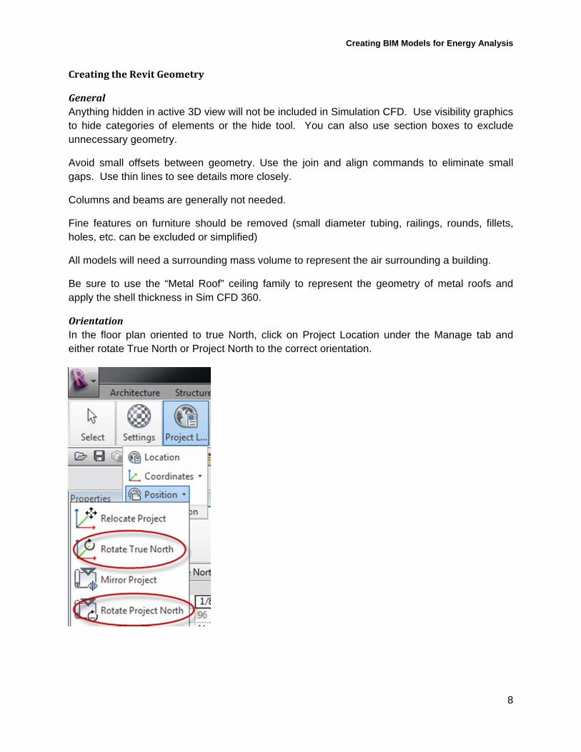
OrientationIn the floor plan oriented to true North, click on Project Location under the Manage tab and either rotate True North or Project North to the correct orientation.

Creating BIM Models for Energy Analysis
9
WindDrivenModelsIf you are performing a wind driven model without any heat transfer, then you can generally use the energy analysis geometry and add masses to represent any surrounding bodies. Just set all of the volumes within the building to be a solid material such as wood. Alternatively you can replace the energy analysis geometry with a similarly shaped mass.
Draw a rectangle In-place mass around the building following AEC best practices on wind loading.
Here, the left picture has the wind coming from the left, while the right picture shows a front view.
Rotate the mass so that one of the vertical surfaces is perpendicular to the direction of the wind that is under investigation.
If you are investigating heat transfer and surface temperatures, then you will need to use the BIM geometry for energy models, but you will want to simplify the model as much as possible as the more complicated the model, the longer the run times. Select specific areas of interest and remove any geometry from the rest of the model that would not impact heat or air flow to that area. Use simple geometry to represent groups of people or other heat sources within the space.

Creating BIM Models for Energy Analysis
10
BuoyancyDrivenModelsSimilar to a wind driven model with heat transfer, you will want to identify specific areas of interest and remove/simplify any geometry that will not influence heat or air flow. Below is an image of the a couple of classrooms where simple masses are used to represent the student bodies, trees, and bushes. Openings and interior walls have been removed from the rest of the model to reduce complexity. The roof and an exterior wall have been hidden for visual purposes only.

Creating BIM Models for Energy Analysis
11
The air volume should be a hemisphere that is 6 to 10 times larger than the biggest geometric dimension of the building to avoid any convection heat transfer to the dome representing the sky. You will also need to add a mass that is 6 to 10 feet thick to represent the ground. The following image is the air and ground masses.
RevittoSimulationCFDGo to the 3D view in which you would like to use as the basis for the CFD model and then go to the Add-ins tab and go to Launch Active Model. Alternatively you can export the view’s geometry as the .sat type of CAD file and import it into Simulation CFD or Simulation CFD 360.

Creating BIM Models for Energy Analysis
12
When you first bring the geometry into Sim CFD 360 you should check the Geometry too and in the Edge Merge tab, the "Edges to be Merged" should be equal to "0".
In the Small Objects tab, the "Object Smaller than Minimum" should have both "Surfaces" and "Edges" equal to "0" as well
Once these settings are confirmed, close the Geometry Tools dialog.
Next verify that the correct units were applied to the geometry by inspecting the height or length of a known dimension. If the units are not correct, right click on the geometry in the project tree and select

Creating BIM Models for Energy Analysis
13
Depending on what units were used in your Revit model, you will have to play with different combinations of switching units with and without checking the Change units box seen below.
ApplyMaterials
WindDrivenModelswithnoTemperaturesSimple wind driven models where surface or air temperatures are not being investigated only need for the air material applied to the volumes where airflow occurs and a single solid materials such as hardwood applied to the solid geometry of a building.
Additionally you can suppress all components other than the outside air box speed up runtimes.
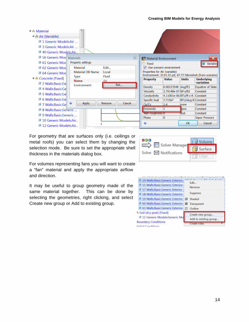
WindDrivenwithTemperaturesorBuoyancyDrivenModelsFor wind or buoyancy driven models where the effects of solar radiation or other sources of thermal energy will have an impact on the air flow it is important to apply the appropriate or the most similar materials from the library. If a material that you need isn’t listed you can create a new one or copy and modify existing ones. For solids, you should pay particularly close attention to the emissivity as it will have a significant impact on the surface temperatures.
The sky emissivity will be based upon the emissivity applied to the air and can vary for 0.3 to 1 depending on location, season, time of day, cloudiness, and air moisture. Typical values range between 0.65 and 0.75. Be sure to research and apply an air emissivity as accurately as possible for your given scenario.
It is also important to set the air Environment setting to variable otherwise the density of the air will not change and there will be little to no air movement in your model.
Creating BIM Models for Energy Analysis
14
For geometry that are surfaces only (i.e. ceilings or metal roofs) you can select them by changing the selection mode. Be sure to set the appropriate shell thickness in the materials dialog box.
For volumes representing fans you will want to create a “fan” material and apply the appropriate airflow and direction.
It may be useful to group geometry made of the same material together. This can be done by selecting the geometries, right clicking, and select Create new group or Add to existing group.

Creating BIM Models for Energy Analysis
15
BoundaryConditions
WindDrivenModelsFor the vertical surface of the air volume apply a velocity boundary condition at the wind speed of interest.
For the right, top, and left faces of the air volume apply a Slip/Symmetry boundary condition.
For the back of the air volume apply a zero atmospheric gauge pressure.
BuoyancyDrivenModelsIf the study is being done during the day apply the ambient temperature to the surface of the dome of the air volume. If it is being done at night, the surface can be up to 15 deg C cooler than the ambient temperature depending on location and climate.
If your building is surrounded by vegetation, it is recommended to apply temperature boundary conditions to the surfaces of their representative volumes. Grassy fields can be 2 to 5 deg C cooler than the ambient air. Trees and bushes can be 5 to 10 deg C cooler.

Creating BIM Models for Energy Analysis
16
If your building is surrounded by dirt or concrete then you will need to apply temperature boundary condition to the bottom of the represented volume approximately equal to the average ground temperature which is typically equal to the average of the seasonal diurnal extremes.
For volumes representing human bodies or other sources of thermal energy apply a Total heat generation boundary condition.
ApplytheMeshMeshing the model well is essential to getting accurate results. You must ensure that the mesh is small enough to accurately model the fluid flow, while also making sure that it is not too small, so as to limit computational impact.
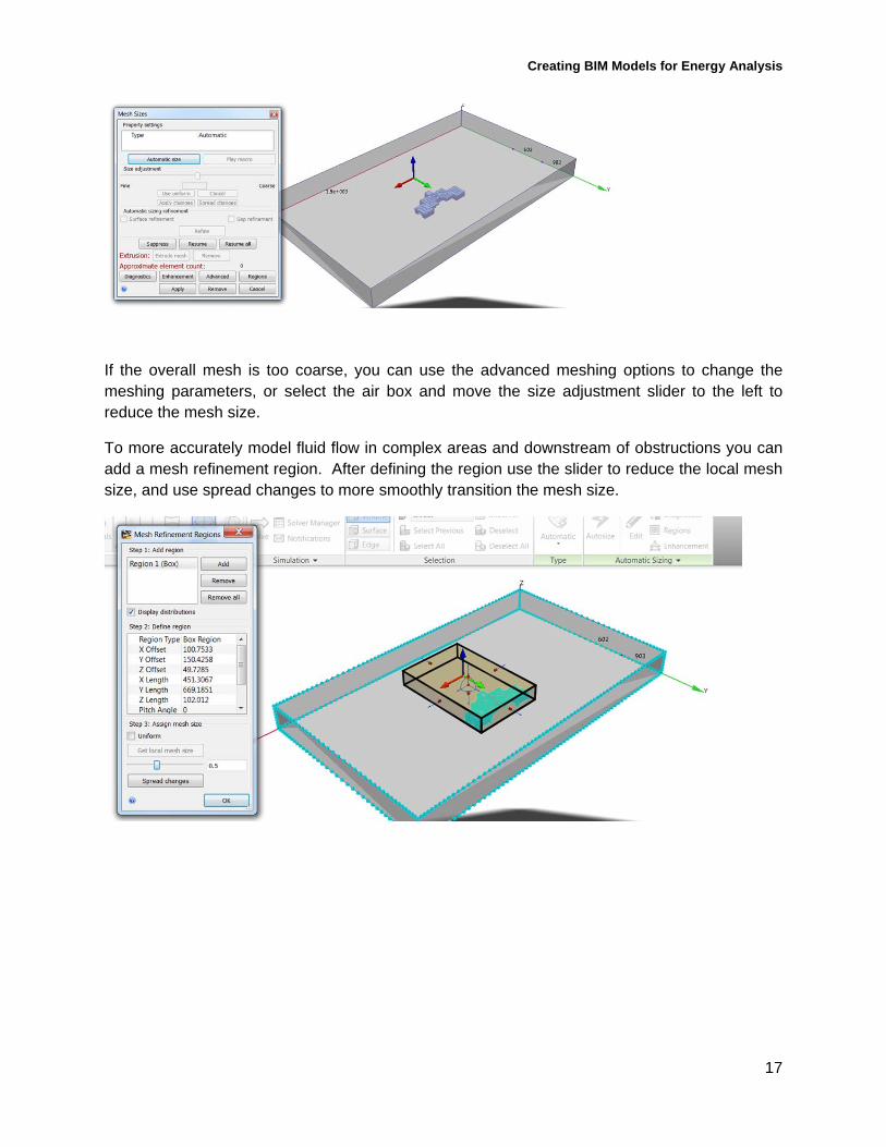
Have the computer automatically generate a mesh by clicking edit next to the autosize button, and then clicking automatic size. This is a good starting point for further mesh refinement.
Creating BIM Models for Energy Analysis
17
If the overall mesh is too coarse, you can use the advanced meshing options to change the meshing parameters, or select the air box and move the size adjustment slider to the left to reduce the mesh size.
To more accurately model fluid flow in complex areas and downstream of obstructions you can add a mesh refinement region. After defining the region use the slider to reduce the local mesh size, and use spread changes to more smoothly transition the mesh size.
Creating BIM Models for Energy Analysis
18
Solving
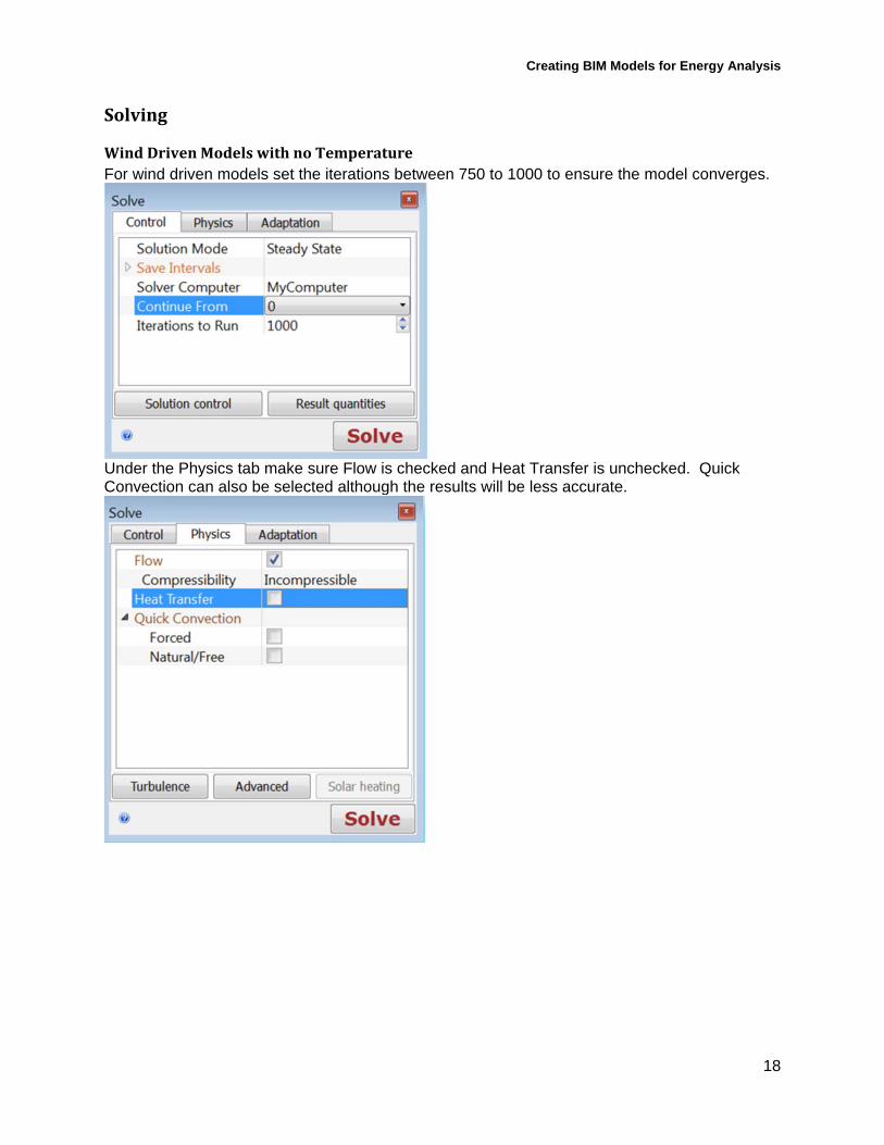
WindDrivenModelswithnoTemperatureFor wind driven models set the iterations between 750 to 1000 to ensure the model converges.
Under the Physics tab make sure Flow is checked and Heat Transfer is unchecked. Quick Convection can also be selected although the results will be less accurate.

Creating BIM Models for Energy Analysis
19
For a wind driven model of the external airflow around Autodesk’s HQ in San Rafael at 111 McInnis the following analysis took approximately 1 hour to solve.
BuoyancyDrivenModelsorWindDrivenModelswithTemperaturesFor wind driven models set the iterations between 750 to 1000 to ensure the model converges. Under the Physics tab, make sure Flow, Heat Transfer, and Radiation are checked. Be sure the direction of Gravity is in the correct direction. Click the Solar heating tab and set the location, time zone, time and date. Make sure the Celestial orientation is pointing in the correct direction.
Creating BIM Models for Energy Analysis
20
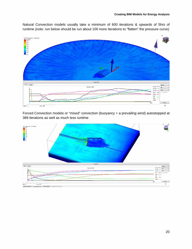
Natural Convection models usually take a minimum of 600 iterations & upwards of 5hrs of runtime (note: run below should be run about 100 more iterations to “flatten” the pressure curve)
Forced Convection models or “mixed” convection (buoyancy + a prevailing wind) autostopped at 389 iterations as well as much less runtime

Creating BIM Models for Energy Analysis
21
ViewingtheResultsThe results are now available for viewing in the Design Study Bar. There are many ways you can view the results.
VelocityMagnitudeGo to the "Results" tab and select "Planes" and Then select "Add"
A 2D slice has been created through the air box so you can see the velocity results.
You can right click anywhere in the window and choose "Add Plane" if you would like to add another plane.
If you would like to move the planes, you can select the arrows and drag them through the model. The blue arrows can be dragged to move the plane
Creating BIM Models for Energy Analysis
22
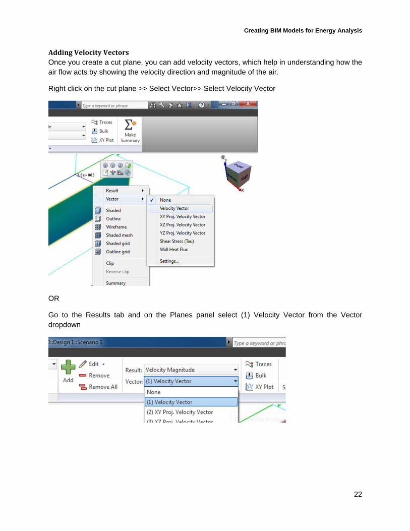
AddingVelocityVectorsOnce you create a cut plane, you can add velocity vectors, which help in understanding how the air flow acts by showing the velocity direction and magnitude of the air.
Right click on the cut plane >> Select Vector>> Select Velocity Vector
OR
Go to the Results tab and on the Planes panel select (1) Velocity Vector from the Vector dropdown

Creating BIM Models for Energy Analysis
23
If you would like to adjust the vector settings go to the Edit button and select "Vector Settings".
You can adjust the Grid Spacing and Length as desired.
Here are the results with vectors added. The different lengths and colors show velocity magnitude

Creating BIM Models for Energy Analysis
24
AddingIso‐surfacesIso-surfaces are three dimensional surfaces of a constant value of a quantity. These help visualize the velocity distributions of complex flows and can be used to find the maximum and minimum values in a model.
Go to the Results tab>> Select Iso Surfaces
Select Add from the Iso Surfaces panel.
Right click the iso surface and select Edit. You can adjust the slider bar to adjust the value of the iso quantity.

Creating BIM Models for Energy Analysis
25
AddingTraceParticles
Particles help you understand the flow path, circulation and regions of swirl.
Select a plane and orient the view so that the view is aligned to the y-axis so that the analysis plane is perpendicular to the flow of air.
Right click on the plane and select Traces or left click and select the "View and Animate flow paths" icon.
ManuallyaddingTracepointsSelect "Add Points" if you would like to manually place points. Once you add points, select "Add Trace Set".

Creating BIM Models for Energy Analysis
26
CreatingagridoftracepointsIf you do not want to manually, you can change the seeding method from "Pick on Plane" to "Rectangular grid" >> Check "Use grid spacing" >> Select "Add trace set"
You may also select to manually place the points (one by one, in a rectangular pattern, or in a circular pattern). This can be useful if you only wish to analyze one part of the flow. Note that point placement may be made easier by dragging the plane on which you are making them to a specific area (e.g. moving the plane to just before the air meets the building).
AnimatingFlowPathsRight click on the plane and select Traces or left click and select the "View and Animate flow paths" icon. Select the trace list you wish to animate. Check the "Incremental" box. Select "Start" to begin the animation.

Creating BIM Models for Energy Analysis
27
To delete traces, left click the plane and Select the "View and Animate Flow Paths" icon.
Select the desired Trace set >> Select "Delete" >> Save the View Settings
If you have views you had created that you may want to revisit, you can save the view by right clicking in the model area and select "Save View.
An .XVS file is created so that you can open the model right to the saved view. You can also save a dynamic image if you would like animated models to be viewed outside of the model.
Creating BIM Models for Energy Analysis
28
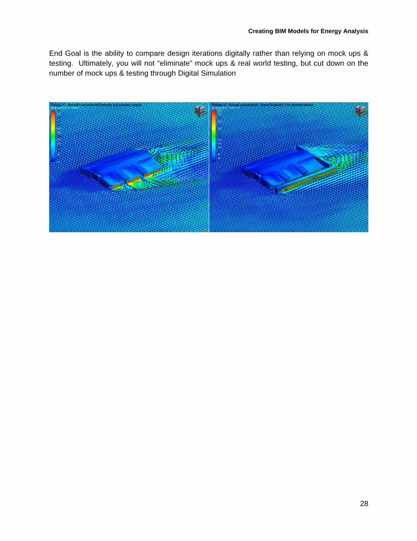
End Goal is the ability to compare design iterations digitally rather than relying on mock ups & testing. Ultimately, you will not “eliminate” mock ups & real world testing, but cut down on the number of mock ups & testing through Digital Simulation
Creating BIM Models for Energy Analysis
29
UsefulResources
CFDesign Advanced Training. http://www.cfdesign.com/Support/CustomerPortal/CFD-university/AdvancedTraining/AEC.aspx
Autodesk Simulatoin CFD Learning Resources. http://www.cfdesign.com/OnlineHelp/2013/Examples/Learning.htm
Natural Ventilation Example. CFDesign Learning Resources. http://www.cfdesign.com/OnlineHelp/2013/Training/AEC/Natural-ventiliation.htm
Geometry Modeling Techniques for AEC Applications. CFDesign Learning Resources. http://www.cfdesign.com/OnlineHelp/2013/Training/AEC/geometry-prep-techniques.htm