level measurement - fine controls (uk) ltd | fine controls (uk) ltd · level measurement continuous...
TRANSCRIPT

Level MeasurementContinuous level measurement - Radar transmitters
SITRANS LR250
5/222Siemens FI 01 · 2011
5
■ Overview
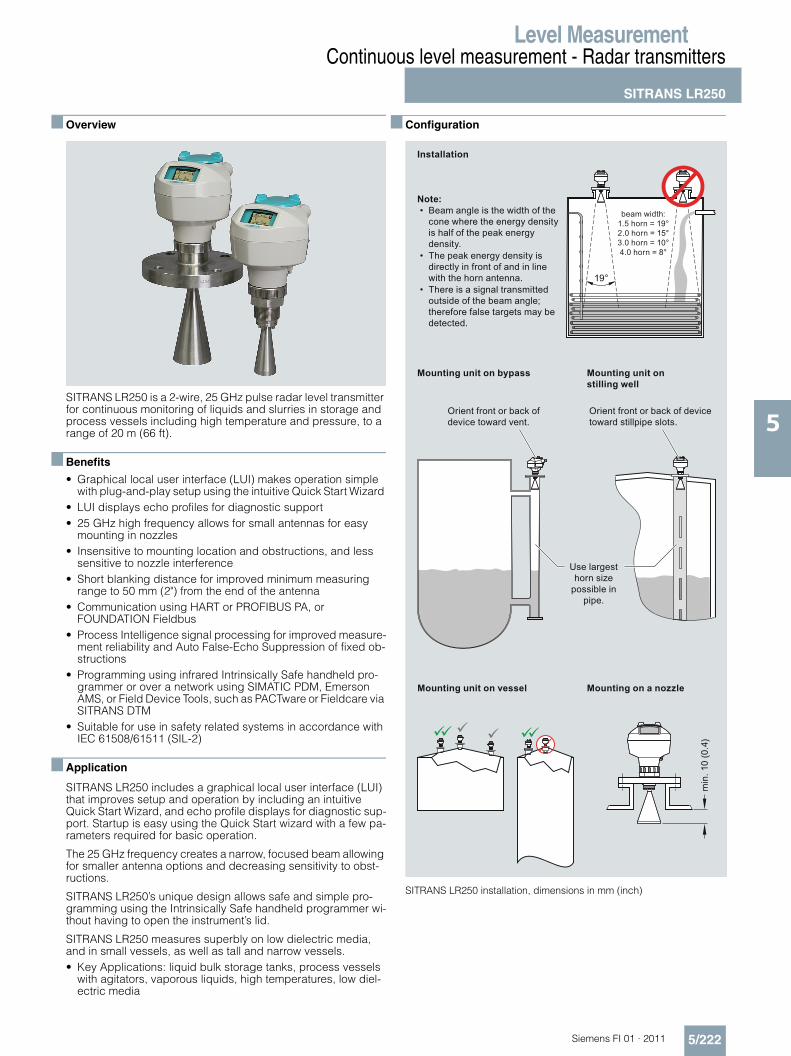
SITRANS LR250 is a 2-wire, 25 GHz pulse radar level transmitter for continuous monitoring of liquids and slurries in storage and process vessels including high temperature and pressure, to a range of 20 m (66 ft).
■ Benefits
• Graphical local user interface (LUI) makes operation simple with plug-and-play setup using the intuitive Quick Start Wizard
• LUI displays echo profiles for diagnostic support• 25 GHz high frequency allows for small antennas for easy
mounting in nozzles• Insensitive to mounting location and obstructions, and less
sensitive to nozzle interference• Short blanking distance for improved minimum measuring
range to 50 mm (2") from the end of the antenna• Communication using HART or PROFIBUS PA, or
FOUNDATION Fieldbus• Process Intelligence signal processing for improved measure-
ment reliability and Auto False-Echo Suppression of fixed ob-structions
• Programming using infrared Intrinsically Safe handheld pro-grammer or over a network using SIMATIC PDM, Emerson AMS, or Field Device Tools, such as PACTware or Fieldcare via SITRANS DTM
• Suitable for use in safety related systems in accordance with IEC 61508/61511 (SIL-2)
■ Application
SITRANS LR250 includes a graphical local user interface (LUI) that improves setup and operation by including an intuitive Quick Start Wizard, and echo profile displays for diagnostic sup-port. Startup is easy using the Quick Start wizard with a few pa-rameters required for basic operation.
The 25 GHz frequency creates a narrow, focused beam allowing for smaller antenna options and decreasing sensitivity to obst-ructions.
SITRANS LR250’s unique design allows safe and simple pro-gramming using the Intrinsically Safe handheld programmer wi-thout having to open the instrument’s lid.
SITRANS LR250 measures superbly on low dielectric media, and in small vessels, as well as tall and narrow vessels.• Key Applications: liquid bulk storage tanks, process vessels
with agitators, vaporous liquids, high temperatures, low diel-ectric media
■ Configuration
SITRANS LR250 installation, dimensions in mm (inch)
Mounting unit on vessel
Mounting unit on stilling well
Mounting on a nozzle
Installation
Orient front or back of device toward stillpipe slots.
Orient front or back of device toward vent.
Use largest horn size
possible in pipe.
beam width:1.5 horn = 19°2.0 horn = 15°3.0 horn = 10°4.0 horn = 8°
Beam angle is the width of the cone where the energy density is half of the peak energy density.
Note:•
The peak energy density is directly in front of and in line with the horn antenna.
•
There is a signal transmitted outside of the beam angle; therefore false targets may be detected.
•
min
. 10
(0.4
)
Mounting unit on bypass
19°

Level MeasurementContinuous level measurement - Radar transmitters
SITRANS LR250
5/223 Siemens FI 01 · 2011
5
■ Technical specifications
Mode of operation
Measuring principle Radar level measurement
Frequency K-band (25.0 GHz)
Minimum measuring range 50 mm (2") from end of antenna
Maximum measuring range 20 m (65 ft), antenna dependent
Output
HART®: Version 5.1
• Analog output 4 ... 20 mA
• Accuracy 0.02 mA
• Fail-safe • Programmable as high low or hold (loss of echo)
• NE 43 programmable
PROFIBUS PA: Profile 3.1
• Function blocks 2 Analog Input (AI)
FOUNDATION FieldbusTM H1
• Functionality Basic or LAS
• Version ITK 5.2.0
• Function blocks 2 Analog Input (AI)
Performance (according toreference conditions IEC60770-1)
Maximum measured error 5 mm (0.2")
Influence of ambient temperature <0.003 %/K
Rated operating conditions
Installation conditions
• Location Indoor/outdoor
Ambient conditions (enclosure)
• Ambient temperature -40 ... +80 °C (-40 ... +176 °F)
• Installation category I
• Pollution degree 4
Medium conditions
Dielectric constant r r > 1.6, antenna and application dependent
Process temperature -40 ... +200 °C (-40 ... +392 °F) (at process connection with FKM o-ring)-20 ... +200 °C (-4 ... +392 °F) (at process connection with FFKM o-ring)
Process pressure Up to 40 bar g (580 psi g), pro-cess connection and tempera-ture dependent.See Pressure/Temperature cur-ves for more information
Design
Enclosure
• Material Aluminium, polyester powder-coated
• Cable inlet 2 x M20x1.5 or 2 x ½" NPT
Degree of protection Type 4X/NEMA 4X, Type 6/NEMA 6, IP67, IP68
Weight < 3 kg (6.6 lbs) 3.75 mm (1½") threaded connection with 1½" horn antenna
Display (local) Graphic local user interface inclu-ding quick start wizard and echo profile display
Antenna
• Material 316L stainless steel [optional alloy N06022/2.4602 (Hastelloy® C-22® or equivalent)]
• Dimensions (nominal horn sizes) Standard 1.5" (40 mm), 2" (48 mm), 3" (75 mm), 4" (95 mm) horn and optional 100 mm (4") horn extension
Process connections
• Process connection 11½" or 2" NPT [(Taper), ANSI/ASME B1.20.1]R 1½" or 2" [(BSPT), EN 10226]G 1½" or 2" [(BSPP), EN ISO 228-1]
• Flange connection 2", 3", 4" (ANSI 150, 300 lbs), 50, 80, 100 mm (PN 16, 40, JIS 10K)
Power supply 4 ... 20 mA/HART Nominal 24 V DC (max. 30 V DC)
with max. 550 PROFIBUS PA • 15 mA
• per IEC 61158-2 FOUNDATION Fieldbus • 20.0 mA
• per IEC 61158-2
Certificates and approvals General CSAUS/C, CE, FM, NE 21, C-TICKRadio FCC, Industry Canada and
Europe ETSI EN 302-372, C-TICKHazardous
• Intrinsically Safe (Europe) ATEX II 1G Ex ia IIC T4ATEX II 1D Ex tD A20 IP67 T90°C
• Non-sparking/Energy Limited (Europe)
ATEX II 3G Ex nA/nL IIC T4 Gc
• Intrinsically Safe (Canada/USA) CSA/FM Class I, Div. 1, Groups A, B, C, D; Class II, Div. 1, Groups E, F, G; Class III T4
• Non-incendive (Canada/USA) CSA/FM Class I, Div. 2, Groups A, B, C, D T5
• Intrinsically Safe (International) IECEx Ex ia IIC T4, Ex tD A20 IP67 T90°C
• Intrinsically Safe (Brazil) INMETRO Br-Ex ia IIC T4• Flame Proof (International/Europe) IECEx/ATEX II 1/2 GD, 1D, 2D,
Ex dmbia IIC T4 Ga/Gb, Ex tD A20 IP67 T90°C
• Increased Safety (International/Europe)
IECEx/ATEX II 1/2 GD, 1D, 2D, Ex embia IIC T4 Ga/Gb, Ex tD A20 IP67 T90°C
• Increased Safety (Brazil) INMETRO Br-Ex embia IIC T4• Explosion Proof (Canada/USA) CSA/FM Class I, Div. 1, Groups A,
B, C, D; Class II, Div. 1, Groups E, F, G; Class III T4
• Explosion Proof (Brazil) INMETRO Br-Ex dmbia IIC T4Marine • Lloyd’s Register of Shipping
• ABS Type Approval • Bureau Veritas
Functional Safety SIL-2 suitable in accordance with IEC 61508/61511
Level MeasurementContinuous level measurement - Radar transmitters
SITRANS LR250
5/224Siemens FI 01 · 2011
5
®HART is a registered trademark of the Hart Communications Foundation. TMFOUNDATION Fieldbus is a trademark of Fieldbus Foundation. ®Hastelloy and ®C-22 are registered trademarks of Haynes International Inc.
ProgrammingIntrinsically Safe Siemens handheld programmer
Infrared receiver
• Approvals for handheld program-mer
IS model:ATEX II 1 GD Ex ia IIC T4 GaEx ia D 20 T135°C Ta = -20 ...+50 °CCSA/FM Class I, II, III, Div. 1, Groups A, B, C, D, E, F, G, T6 Ta = +50 °CIECEx SIR 09.0073
Handheld communicator HART communicator 375/475PC • SIMATIC PDM
• Emerson AMS • SITRANS DTM (for connection
into FDT, such as PACTware or Fieldcare)
Display (local) Graphic local user interface inclu-ding quick start wizard and echo profile displays

Level MeasurementContinuous level measurement - Radar transmitters
SITRANS LR250
5/225 Siemens FI 01 · 2011
5
C) Subject to export regulations AL: N, ECCN: EAR99
Selection and Ordering data Order No.
SITRANS LR2502-wire, 25 GHz pulse radar level transmitter for con-tinuous monitoring of liquids and slurries in storage and process vessels including high temperature and pressure, to a range of 20 m (66 ft). Ideal for small vessels and low dielectric media.
C) 7 M L 5 4 3 1 -
7777 0 - 7777
Process Connection and Antenna Material316L (1.4435 or 1.4404) stainless steel, PTFE emitter, FKM seal
0
316L (1.4435 or 1.4404) stainless steel,PTFE emitter, FFKM seal
1
Hastelloy C-22/2.4602, PTFE emitter, FKM seal1) 2) 2
Hastelloy C-22/2.4602, PTFE emitter, FFKM seal1) 2) 3
Process Connection Type1½" NPT [(Taper), ANSI/ASME B1.20.1]3) A AR 1½" [(BSPT), EN 10226]2) A BG 1½" [(BSPP), EN ISO 228-1] (parallel thread)3) A C
2" NPT [(Taper), ANSI/ASME B1.20.1] A DR 2" [(BSPT), EN 10226] A EG 2" [(BSPP), EN ISO 228-1] (parallel thread) A F
2" Class 150 ASME B16.5 flat faced4) B A3" Class 150 ASME B16.5 flat faced4) B B4" Class 150 ASME B16.5 flat faced4) B C
2" Class 300 ASME B16.5 flat faced4) C A3" Class 300 ASME B16.5 flat faced4) C B4" Class 300 ASME B16.5 flat faced4) C C
DN 50 PN 16 EN 1092-1 Type A flat faced4) D ADN 80 PN 16 EN 1092-1 Type A flat faced4) D BDN 100 PN 16 EN 1092-1 Type A flat faced4) D C
DN 50 PN 40 EN 1092-1 Type A flat faced4) E ADN 80 PN 40 EN 1092-1 Type A flat faced4) E BDN 100 PN 40 EN 1092-1 Type A flat faced4) E C
50A 10K JIS B 2220 flat faced4) F A80A 10K JIS B 2220 flat faced4) F B100A 10K JIS B 2220 flat faced4) F C
DN 50 PN 16 DIN EN1092-1 Type B1 raised face G ADN 80 PN 16 DIN EN1092-1 Type B1 raised face G BDN 100 PN 16 DIN EN1092-1 Type B1 raised face G C
DN 150 PN 16 DIN EN1092-1 Type B1 raised face G DDN 50 PN 40 DIN EN1092-1 Type B1 raised face H ADN 80 PN 40 DIN EN1092-1 Type B1 raised face H B
DN 100 PN 40 DIN EN1092-1 Type B1 raised face H CDN 150 PN 40 DIN EN1092-1 Type B1 raised face H D
Communication/OutputPROFIBUS PA 14 ... 20 mA, HART®, startup at < 3.6 mA 2FOUNDATION FieldbusTM 3
Enclosure/Cable inletAluminum, Epoxy painted2 x ½" NPT 02 x M20x1.5 1
Antenna
1½" horn5) A
2" horn (fits 2" ASME or DN 50 nozzles) B
3" horn (fits 3" ASME or DN 80 nozzles) C
4" horn (fits 4" ASME or DN 100 nozzles) D
1½" horn with 100 mm extension5) E
2" horn with 100 mm extension F
3" horn with 100 mm extension G
4" horn with 100 mm extension(Note: Please use largest horn size possible.)
H
ApprovalsGeneral Purpose, CE, CSA, FM, FCC, R&TTE, C-TICK
A
Intrinsically Safe, CSA/FM Class I, II, III, Div. 1, Groups A, B, C, D, E, F, G, FCC
B
Intrinsically Safe, IECEx/ATEX II 1 GD Ex ia IIC T4, Ex tD A20 IP67 T90°C, R&TTE, C-TICK, INMETRO Br-Ex ia IIC T4
C
Non-incendive, CSA/FM Class I, Div. 2, Groups A, B, C, D, FCC
D
Non-sparking, Energy Limited, ATEX II 3G Ex nA/nL IIC T4, CE, R&TTE, C-TICK
E
Increased Safety, IECEx/ATEX II 1/2 GD Ex embia IIC T4, Ex tD A20 IP67 T90°C, CE, R&TTE, C-TICK, , INMETRO Br-Ex embia IIC T46)
F
Flame Proof, IECEx/ATEX II 1/2 GD Ex dmbia IIC T4, Ex tD A20 IP67 T90°C, CE, R&TTE, C-TICK, INMETRO BR-Ex dmbia IIC T46)
G
Explosion Proof CSA/FM Class I, II, III, Div. 1, Gr. A, B, C, D, E, F, G, FCC 6)
H
Pressure ratingRating per Pressure/Temperature curves in manual 00.5 bar g (7.25 psi g) maximum 1
1) Not available with process connection options AA to AF2) Hastelloy flanges are provided as raised face. 3) For 1½" horn antennas only, max. range 10 m (32.8 ft), dk > 34) Siemens Milltronics type flange (flange bolting patterns and facings dimen-
sionally correspond to the applicable ASME B16.5, or EN 1092-1, or JIS B 2220 standard), see operating instructions for details
5) For 1½" threaded connection only, max. range 10 m (32.8 ft), dk > 36) Applicable to Communication option 2 only
Selection and Ordering data Order No.
SITRANS LR2502-wire, 25 GHz pulse radar level transmitter for con-tinuous monitoring of liquids and slurries in storage and process vessels including high temperature and pressure, to a range of 20 m (66 ft). Ideal for small vessels and low dielectric media.
C) 7 M L 5 4 3 1 -
7777 0 - 7777

Level MeasurementContinuous level measurement - Radar transmitters
SITRANS LR250
5/226Siemens FI 01 · 2011
5C) Subject to export regulations AL: N, ECCN: EAR99
D)Subject to export regulations AL: N, ECCN: EAR99H
Selection and Ordering data Order code
Further designs
Please add "-Z" to Order No. and specify Order code(s).
Plug M12 with mating Connector 1) 2) 3) A50
Plug 7/8" with mating Connector2) 3) 4) A55
Stainless steel tag [69 x 50 mm (2.71 x 1.97")]: Measuring-point number/identification (max. 27 characters); specify in plain text
Y15
Test certificate: Manufacturer's test certificate M to DIN 55350, Part 18 and to ISO 9000
C11
Inspection Certificate Type 3.1 per EN 10204 C12
Functional Safety - SIL2 suitable in accordance with IEC 61508/615113) 5)
C20
Namur NE43 compliant, device preset to failsafe <3.6 mA5)
N07
Operating Instructions for HART/mA device Order No.
English C) 7ML1998-5JE03
GermanNote: The Operating Instructions should be orde-red as a separate line item on the order.
C) 7ML1998-5JE33
Multi-language Quick Start manual This device is shipped with the Siemens Milltronics manual CD containing the complete ATEX Quick Start and Operating Instructions library.
C) 7ML1998-5QX82
Operating Instructions for PROFIBUS PA device
English C) 7ML1998-5JF03
GermanNote: The Operating Instructions should be orde-red as a separate line item on the order.
C) 7ML1998-5JF33
Multi-language Quick Start manual This device is shipped with the Siemens Milltronics manual CD containing the complete ATEX Quick Start and Operating Instructions library.
C) 7ML1998-5XE82
Operating Instructions for FOUNDATION Field-bus device
English C) 7ML1998-5KL01
GermanNote: The Operating Instructions should be orde-red as a separate line item on the order.
C) 7ML1998-5KL31
Multi-language Quick Start manual This device is shipped with the Siemens Milltronics manual CD containing the complete ATEX Quick Start and Operating Instructions library.
C) 7ML1998-5XN81
Accessories
Handheld programmer, Intrinsically safe, EEx ia C) 7ML1930-1BK
HART modem/RS-232 (for use with a PC andSIMATIC PDM)
D) 7MF4997-1DA
HART modem/USB (for use with a PC andSIMATIC PDM)
D) 7MF4997-1DB
One metallic cable gland M20x1.5, rated -40 ... +80 °C (-40 ... +176 °F), HART
7ML1930-1AP
One metallic cable gland M20x1.5, rated -40 ... +80 °C (-40 ... +176 °F), PROFIBUS PA and FOUNDATION Fieldbus6)
7ML1930-1AQ
SITRANS RD100 Remote display - see Chapter 8
SITRANS RD200 Remote display - see Chapter 8
SITRANS RD500 web, datalogging, alarming, ethernet, and modem support for instrumentation - see Chapter 8
1) Available with Enclosure option 1 only2) To be used with Communication options 1 and 3 only.
Connector has IP67 rating.3) Available with Approvals option A, B, or C only4) Available with Enclosure option 0 only5) Applicable to Communication option 2 only6) For use with Communication option 1 and 3 only

Level MeasurementContinuous level measurement - Radar transmitters
SITRANS LR250 Specials
5/227 Siemens FI 01 · 2011
5
SITRANS LR250 Specials
Order No.
SITRANS LR250 Enclosures (PROFIBUS PA models)
LR250 enclosure with board stack, NPT cable inlet, approval option A, with PROFIBUS PA communication, no process connection
C) A5E01156836
LR250 enclosure with board stack, M20 cable inlet, approval option A, withPROFIBUS PA communication,no process connection
C) A5E01156838
LR250 enclosure with board stack,NPT cable inlet, approval option B, withPROFIBUS PA communication,no process connection
C) A5E01156839
LR250 enclosure with board stack, M20 cable inlet, approval option B, withPROFIBUS PA communication,no process connection
C) A5E01156841
LR250 enclosure with board stack, NPT cable inlet, approval option C, withPROFIBUS PA communication,no process connection
C) A5E01156843
LR250 enclosure with board stack, M20 cable inlet, approval option C, withPROFIBUS PA communication,no process connection
C) A5E01156844
LR250 enclosure with board stack, M20 cable inlet, approval option C, withPROFIBUS PA communication,no process connection
C) A5E01156846
LR250 enclosure with board stack, M20 cable inlet, approval option D, withPROFIBUS PA communication,no process connection
C) A5E01156848
SITRANS LR250 Enclosures (FOUNDATION Field-bus models)
LR250 enclosure with board stack, NPT cable inlet, approval option A, withFOUNDATION Fieldbus communication,no process connection
C) A5E02653792
LR250 enclosure with board stack, M20 cable inlet, approval option A, withFOUNDATION Fieldbus communication,no process connection
C) A5E02653793
LR250 enclosure with board stack,NPT cable inlet, approval option C, withFOUNDATION Fieldbus communication,no process connection
C) A5E02654606
LR250 enclosure with board stack,M20 cable inlet, approval option C, withFOUNDATION Fieldbus communication,no process connection
C) A5E02654608
SITRANS LR250 Specials
Order No.
SITRANS LR250 Enclosures (<3.6mA start-up HART models)
LR250 enclosure with board stack, M20 cable inlet, approval option A, with HART® communica-tion start-up at <3.6mA, no process connection
C) A5E02956317
LR250 enclosure with board stack, M20 cable inlet, approval option C, with HART® communica-tion start-up at <3.6mA, no process connection
C) A5E02956319
LR250 enclosure with board stack, M20 cable inlet, approval option E, with HART® communica-tion start-up at <3.6mA, no process connection
C) A5E02956320
LR250 enclosure with board stack, M20 cable inlet, approval option F, with HART® communica-tion start-up at <3.6mA, no process connection
C) A5E02956322
LR250 enclosure with board stack, M20 cable inlet, approval option G, with HART® communica-tion start-up at <3.6mA, no process connection
C) A5E02956323
SITRANS LR250 Enclosures (4 to 20 mA HART models prior to October 2010)
LR250 enclosure with board stack, NPT cable inlet, approval option A, with HART communication, no process connection
C) A5E01156819
LR250 enclosure with board stack, M20 cable inlet, approval option A, with HART communication, no process connection
C) A5E01156820
LR250 enclosure with board stack, NPT cable inlet, approval option B, with HART communication, no process connection
C) A5E01156823
LR250 enclosure with board stack, M20 cable inlet, approval option B, with HART
communication, no process connection
C) A5E01156824
LR250 enclosure with board stack, NPT cable inlet, approval option C, with HART communication, no process connection
C) A5E01156827
LR250 enclosure with board stack, M20 cable inlet, approval option C, with HART communication, no process connection
C) A5E01156832
LR250 enclosure with board stack, NPT cable inlet, approval option D, with HART communication, no process connection
C) A5E01156834
LR250 enclosure with board stack, NPT cable inlet, approval option D, with HART communication, no process connection
C) A5E01156835
LR250 enclosure with board stack, M20 cable inlet, approval option F, with HART® communication, no process connection
C) A5E02448270
LR250 enclosure with board stack,M20 cable inlet, approval option G, with HART® communication, no process connection
C) A5E02448274
LR250 enclosure with board stack,NPT cable inlet, approval option H, with HART® communication, no process connection
C) A5E02448278
Level MeasurementContinuous level measurement - Radar transmitters
SITRANS LR250 Specials
5/228Siemens FI 01 · 2011
5
C) Subject to export regulations AL: N, ECCN: EAR99
J) Subject to export regulations AL: 9I999, ECCN: EAR99Please contact [email protected] for special requests
SITRANS LR250 Specials
Order No.
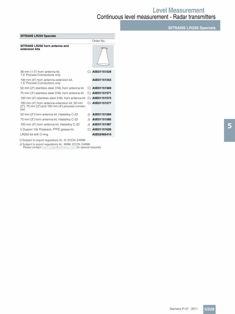
SITRANS LR250 horn antenna andextension kits
38 mm (1.5") horn antenna kit, 1.5" Process Connections only
C) A5E01151539
100 mm (4") horn antenna extension kit, 1.5" Process Connections only
A5E01151553
50 mm (2") stainless steel 316L horn antenna kit C) A5E01151569
75 mm (3") stainless steel 316L horn antenna kit C) A5E01151571
100 mm (4") stainless steel 316L horn antenna kit C) A5E01151573
100 mm (4") horn antenna extension kit, 50 mm (2"), 75 mm (3") and 100 mm (4") process connec-tion
C) A5E01151577
50 mm (2") horn antenna kit, Hastelloy C-22 J) A5E01151584
75 mm (3") horn antenna kit, Hastelloy C-22 J) A5E01151585
100 mm (4") horn antenna kit, Hastelloy C-22 J) A5E01151587
5 Dupont 1Gr Polyback, PTFE grease kit C) A5E01151626
LR250 lid with O-ring A5E02465410
Level MeasurementContinuous level measurement - Radar transmitters
SITRANS LR250 Specials
5/229 Siemens FI 01 · 2011
5
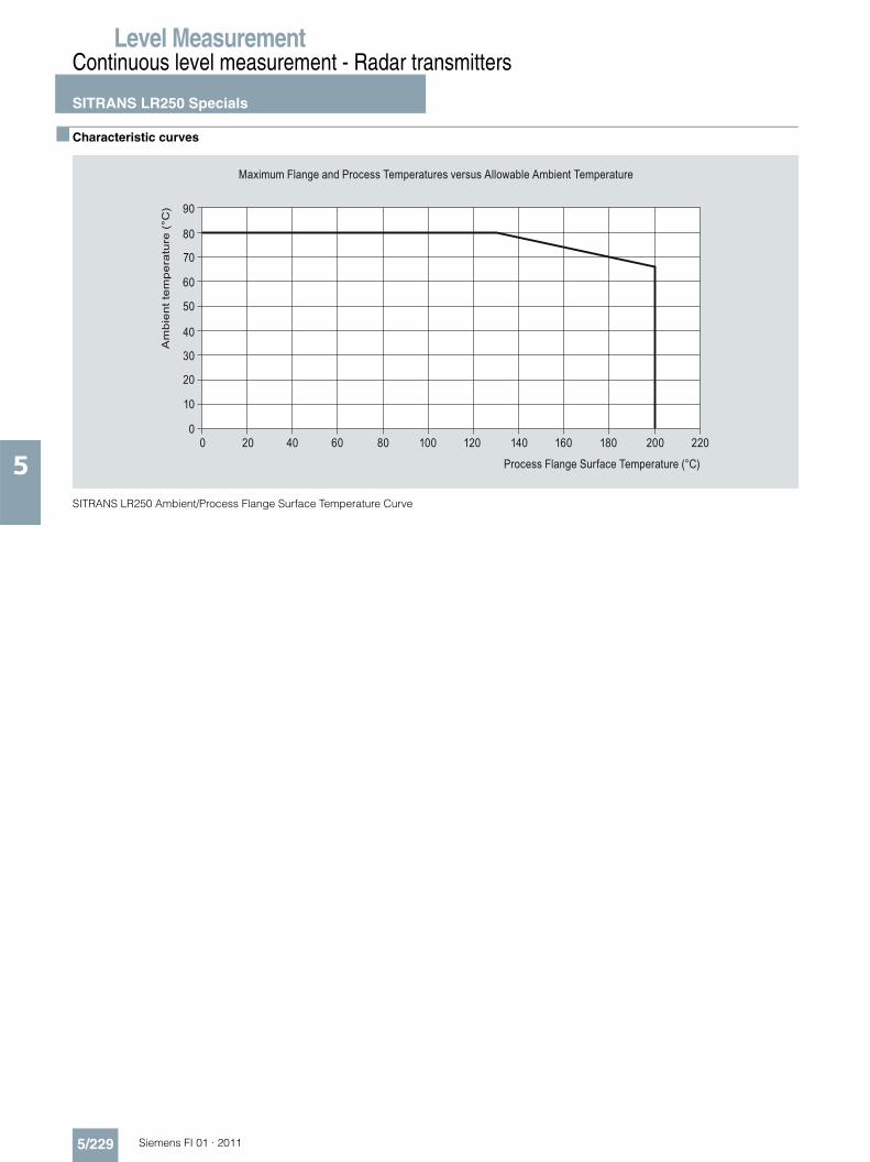
■ Characteristic curves
SITRANS LR250 Ambient/Process Flange Surface Temperature Curve
Maximum Flange and Process Temperatures versus Allowable Ambient Temperature
Process Flange Surface Temperature (°C)
Am
bie
nt t
em
pe
ratu
re (
°C) 90
80
70
60
50
40
30
20
10
00 20 40 60 80 100 120 140 160 180 200 220

Level MeasurementContinuous level measurement - Radar transmitters
SITRANS LR250 Specials
5/230Siemens FI 01 · 2011
5
■ Dimensional drawings
SITRANS LR250, dimensions in mm (inch)
Measurement Range
Beam AngleHorn HeightHorn O.D.Nominal HornSize
8 degrees10 degrees15 degrees19 degrees
Threaded
Flanged enclosure/electronics
nameplate
retaining collar
flange
sensor referencepoint
horn O.D.
hornprocess device tag
optional 100 (3.93)
horn extension
½" NPT cable entry (or alternatively, M20 cable gland)
threaded cover
horn O.D.
horn O.D.
enclosure/electronics
retainingcollar
horn
process device tag
sensor referencepoint
281
(11.
1)
DCBA
20 m (65.6 ft)20 m (65.6 ft)
254 (10)199 (7.85)166 (6.55) 20 m (65.6 ft)
10 m (32.8 ft)135 (5.3)
94.8 (3.73)74.8 (2.94)47.8 (1.88)39.8 (1.57)
100 (4)80 (3)50 (2)
40 (1.5)
D CB
A
187
(7.4
)
121
(4.8
)
109 (4.3)185 (7.3)
28 (1
.1)
158
(6.2
)
154 (6.1)
SITRANS LR250
50 (2.0)
Level MeasurementContinuous level measurement - Radar transmitters
SITRANS LR250 Specials
5/231 Siemens FI 01 · 2011
5
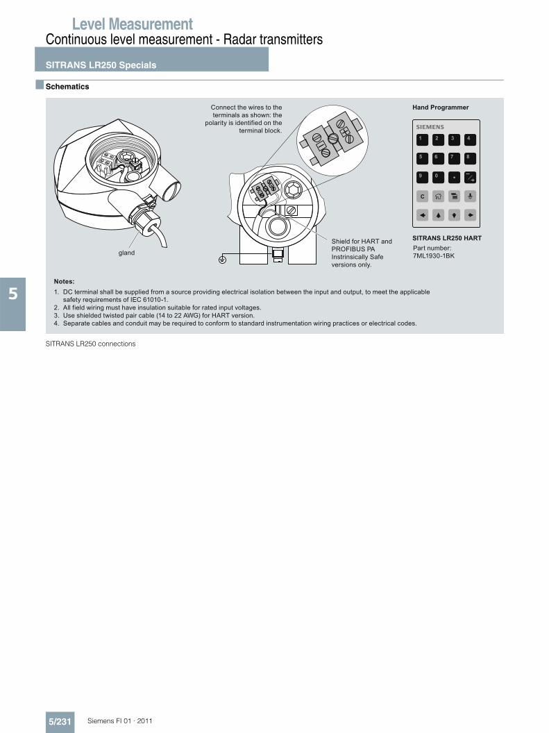
■ Schematics
SITRANS LR250 connections
Part number: 7ML1930-1BK
Hand Programmer
DC terminal shall be supplied from a source providing electrical isolation between the input and output, to meet the applicable safety requirements of IEC 61010-1.
Notes:1.
All field wiring must have insulation suitable for rated input voltages.2.Use shielded twisted pair cable (14 to 22 AWG) for HART version.3.Separate cables and conduit may be required to conform to standard instrumentation wiring practices or electrical codes.4.
Connect the wires to the terminals as shown: the
polarity is identified on the terminal block.
gland
Shield for HART and PROFIBUS PA Instrinsically Safe versions only.
SITRANS LR250 HART