level measurement point level measurement - capacitance ... pdfs... · level measurement point...
TRANSCRIPT
Level MeasurementPoint level measurement - Capacitance switches
Pointek CLS200 - Standard
5/15Siemens FI 01 · 2011
5
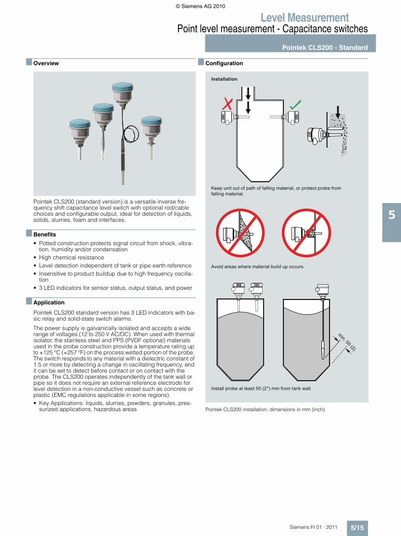
■ Overview
Pointek CLS200 (standard version) is a versatile inverse fre-quency shift capacitance level switch with optional rod/cable choices and configurable output, ideal for detection of liquids, solids, slurries, foam and interfaces.
■ Benefits
• Potted construction protects signal circuit from shock, vibra-tion, humidity and/or condensation
• High chemical resistance• Level detection independent of tank or pipe earth reference• Insensitive to product buildup due to high frequency oscilla-
tion• 3 LED indicators for sensor status, output status, and power
■ Application
Pointek CLS200 standard version has 3 LED indicators with ba-sic relay and solid-state switch alarms.
The power supply is galvanically isolated and accepts a wide range of voltages (12 to 250 V AC/DC). When used with thermal isolator, the stainless steel and PPS (PVDF optional) materials used in the probe construction provide a temperature rating up to +125 °C (+257 °F) on the process wetted portion of the probe. The switch responds to any material with a dielectric constant of 1.5 or more by detecting a change in oscillating frequency, and it can be set to detect before contact or on contact with the probe. The CLS200 operates independently of the tank wall or pipe so it does not require an external reference electrode for level detection in a non-conductive vessel such as concrete or plastic (EMC regulations applicable in some regions).• Key Applications: liquids, slurries, powders, granules, pres-
surized applications, hazardous areas
■ Configuration
Pointek CLS200 installation, dimensions in mm (inch)
Avoid areas where material build up occurs.
Keep unit out of path of falling material, or protect probe from falling material.
Install probe at least 50 (2") mm from tank wall.
Installation
min. 50 (2)
© Siemens AG 2010
Level MeasurementPoint level measurement - Capacitance switches
Pointek CLS200 - Standard
5/16 Siemens FI 01 · 2011
5
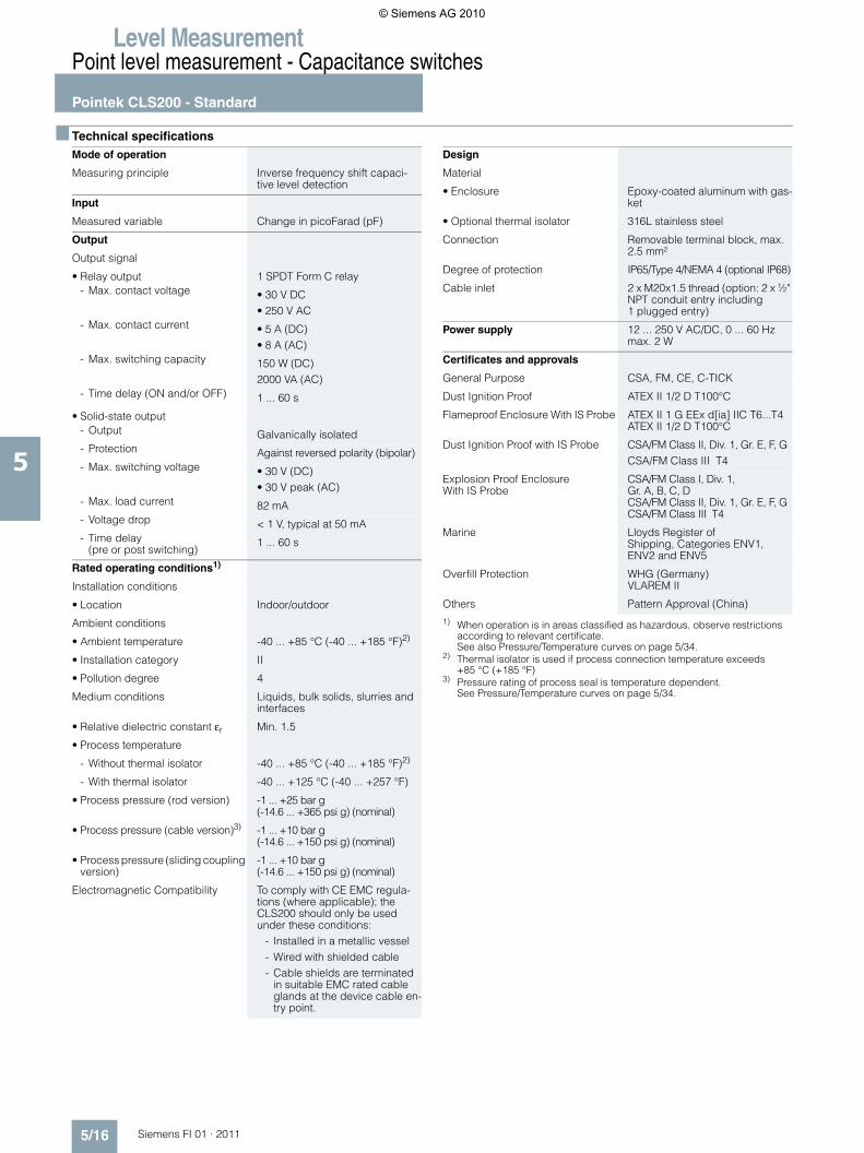
■ Technical specifications
1) When operation is in areas classified as hazardous, observe restrictions according to relevant certificate.See also Pressure/Temperature curves on page 5/34.
2) Thermal isolator is used if process connection temperature exceeds +85 °C (+185 °F)
3) Pressure rating of process seal is temperature dependent.See Pressure/Temperature curves on page 5/34.
Mode of operation
Measuring principle Inverse frequency shift capaci-tive level detection
Input
Measured variable Change in picoFarad (pF)
Output
Output signal
• Relay output 1 SPDT Form C relay- Max. contact voltage • 30 V DC
• 250 V AC - Max. contact current • 5 A (DC)
• 8 A (AC) - Max. switching capacity 150 W (DC)
2000 VA (AC)- Time delay (ON and/or OFF) 1 ... 60 s
• Solid-state output - Output Galvanically isolated- Protection Against reversed polarity (bipolar)- Max. switching voltage • 30 V (DC)
• 30 V peak (AC) - Max. load current 82 mA- Voltage drop < 1 V, typical at 50 mA- Time delay
(pre or post switching) 1 ... 60 s
Rated operating conditions1)
Installation conditions
• Location Indoor/outdoor
Ambient conditions
• Ambient temperature -40 ... +85 °C (-40 ... +185 °F)2)
• Installation category II
• Pollution degree 4
Medium conditions Liquids, bulk solids, slurries and interfaces
• Relative dielectric constant εr Min. 1.5
• Process temperature
- Without thermal isolator -40 ... +85 °C (-40 ... +185 °F)2)
- With thermal isolator -40 ... +125 °C (-40 ... +257 °F)
• Process pressure (rod version) -1 ... +25 bar g(-14.6 ... +365 psi g) (nominal)
• Process pressure (cable version)3) -1 ... +10 bar g(-14.6 ... +150 psi g) (nominal)
• Process pressure (sliding coupling version)
-1 ... +10 bar g(-14.6 ... +150 psi g) (nominal)
Electromagnetic Compatibility To comply with CE EMC regula-tions (where applicable); the CLS200 should only be used under these conditions:
- Installed in a metallic vessel - Wired with shielded cable - Cable shields are terminated
in suitable EMC rated cable glands at the device cable en-try point.
Design
Material
• Enclosure Epoxy-coated aluminum with gas-ket
• Optional thermal isolator 316L stainless steel
Connection Removable terminal block, max. 2.5 mm²
Degree of protection IP65/Type 4/NEMA 4 (optional IP68)
Cable inlet 2 x M20x1.5 thread (option: 2 x ½" NPT conduit entry including1 plugged entry)
Power supply 12 ... 250 V AC/DC, 0 ... 60 Hz max. 2 W
Certificates and approvals
General Purpose CSA, FM, CE, C-TICK
Dust Ignition Proof ATEX II 1/2 D T100°C
Flameproof Enclosure With IS Probe ATEX II 1 G EEx d[ia] IIC T6...T4ATEX II 1/2 D T100°C
Dust Ignition Proof with IS Probe CSA/FM Class II, Div. 1, Gr. E, F, G CSA/FM Class III T4
Explosion Proof Enclosure With IS Probe
CSA/FM Class I, Div. 1,Gr. A, B, C, DCSA/FM Class II, Div. 1, Gr. E, F, GCSA/FM Class III T4
Marine Lloyds Register of Shipping, Categories ENV1, ENV2 and ENV5
Overfill Protection WHG (Germany)VLAREM II
Others Pattern Approval (China)
© Siemens AG 2010
Level MeasurementPoint level measurement - Capacitance switches
Pointek CLS200 - Standard
5/17Siemens FI 01 · 2011
5
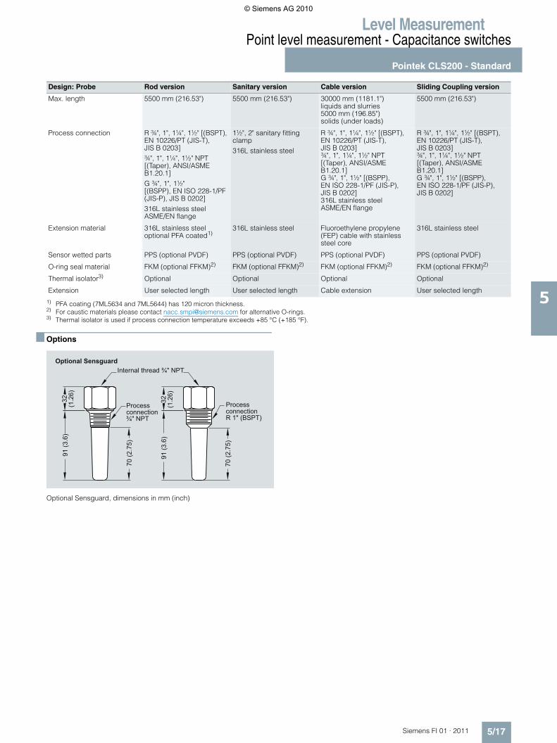
1) PFA coating (7ML5634 and 7ML5644) has 120 micron thickness.2) For caustic materials please contact [email protected] for alternative O-rings.3) Thermal isolator is used if process connection temperature exceeds +85 °C (+185 °F).
■ Options
Optional Sensguard, dimensions in mm (inch)
Design: Probe Rod version Sanitary version Cable version Sliding Coupling version
Max. length 5500 mm (216.53") 5500 mm (216.53") 30000 mm (1181.1")liquids and slurries5000 mm (196.85") solids (under loads)
5500 mm (216.53")
Process connection R ¾", 1", 1¼", 1½" [(BSPT), EN 10226/PT (JIS-T), JIS B 0203]¾", 1", 1¼", 1½" NPT [(Taper), ANSI/ASME B1.20.1]G ¾", 1", 1½"[(BSPP), EN ISO 228-1/PF (JIS-P), JIS B 0202]316L stainless steelASME/EN flange
1½", 2" sanitary fitting clamp316L stainless steel
R ¾", 1", 1¼", 1½" [(BSPT), EN 10226/PT (JIS-T),JIS B 0203]¾", 1", 1¼", 1½" NPT [(Taper), ANSI/ASME B1.20.1]G ¾", 1", 1½" [(BSPP), EN ISO 228-1/PF (JIS-P), JIS B 0202] 316L stainless steel ASME/EN flange
R ¾", 1", 1¼", 1½" [(BSPT), EN 10226/PT (JIS-T),JIS B 0203]¾", 1", 1¼", 1½" NPT [(Taper), ANSI/ASME B1.20.1]G ¾", 1", 1½" [(BSPP), EN ISO 228-1/PF (JIS-P), JIS B 0202]
Extension material 316L stainless steeloptional PFA coated1)
316L stainless steel Fluoroethylene propylene (FEP) cable with stainless steel core
316L stainless steel
Sensor wetted parts PPS (optional PVDF) PPS (optional PVDF) PPS (optional PVDF) PPS (optional PVDF)
O-ring seal material FKM (optional FFKM)2) FKM (optional FFKM)2) FKM (optional FFKM)2) FKM (optional FFKM)2)
Thermal isolator3) Optional Optional Optional Optional
Extension User selected length User selected length Cable extension User selected length
Optional SensguardInternal thread ¾" NPT
Processconnection ¾" NPT
ProcessconnectionR 1" (BSPT)
32(1
.26)
70 (2
.75)
70 (2
.75)
91 (3
.6)
91 (3
.6)
32(1
.26)
© Siemens AG 2010
Level MeasurementPoint level measurement - Capacitance switches
Pointek CLS200 - Standard
5/18 Siemens FI 01 · 2011
5
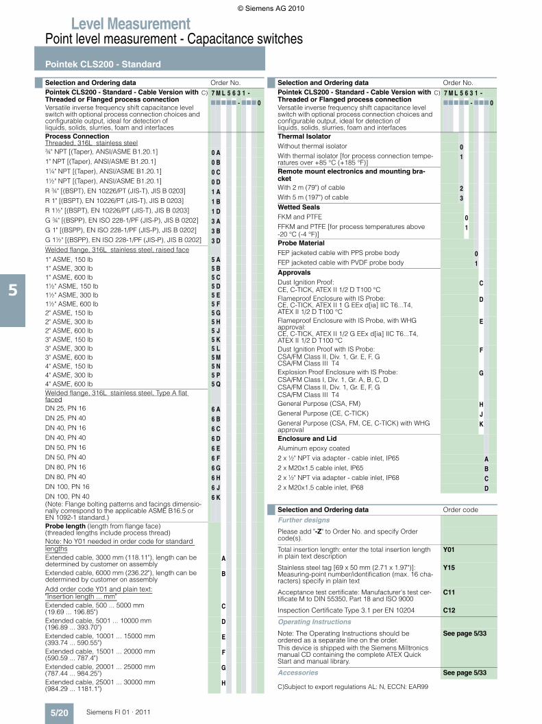
C) Subject to export regulations AL: N, ECCN: EAR99
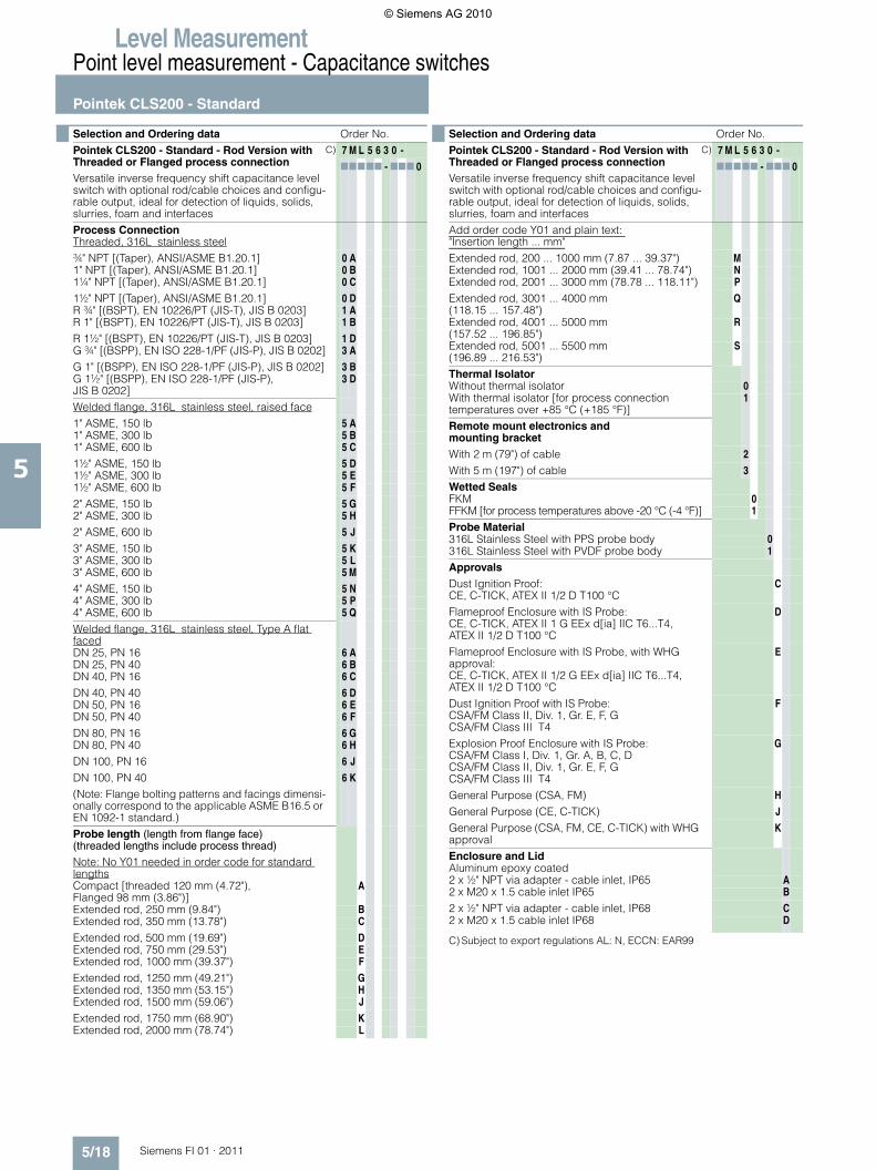
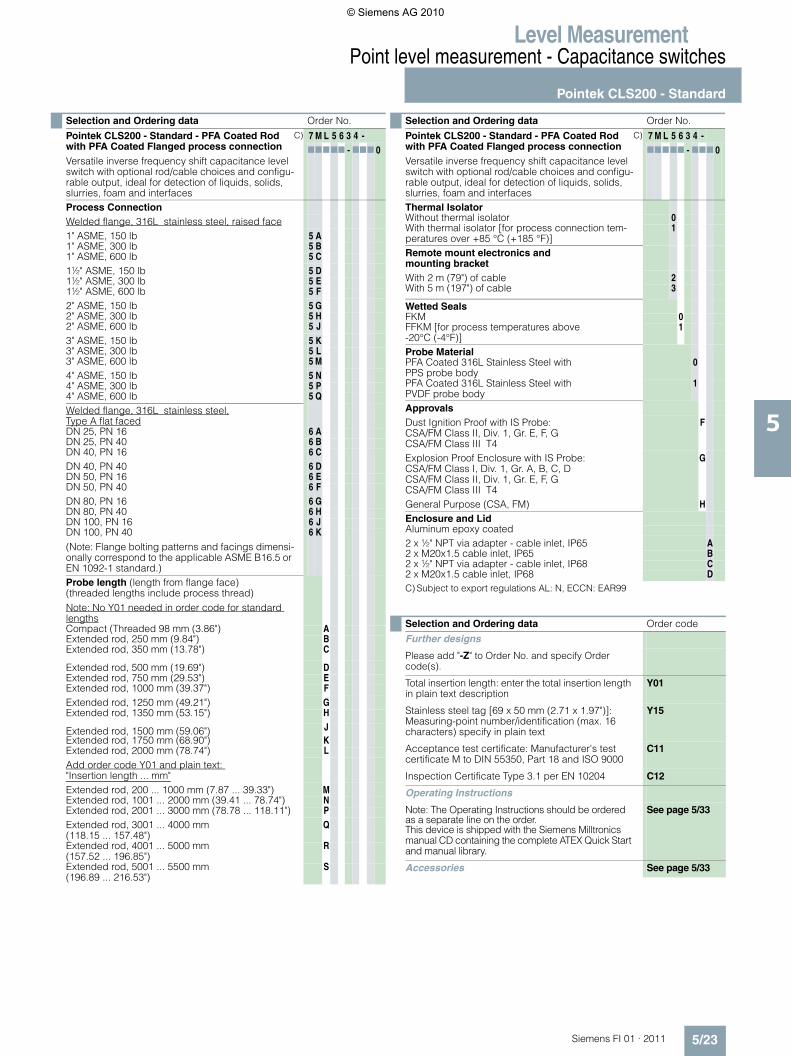
Selection and Ordering data Order No.Pointek CLS200 - Standard - Rod Version with Threaded or Flanged process connectionVersatile inverse frequency shift capacitance level switch with optional rod/cable choices and configu-rable output, ideal for detection of liquids, solids, slurries, foam and interfaces
C) 7 M L 5 6 3 0 -77777 - 777 0
Process ConnectionThreaded, 316L stainless steel¾" NPT [(Taper), ANSI/ASME B1.20.1] 0 A1" NPT [(Taper), ANSI/ASME B1.20.1] 0 B1¼" NPT [(Taper), ANSI/ASME B1.20.1] 0 C
1½" NPT [(Taper), ANSI/ASME B1.20.1] 0 DR ¾" [(BSPT), EN 10226/PT (JIS-T), JIS B 0203] 1 AR 1" [(BSPT), EN 10226/PT (JIS-T), JIS B 0203] 1 B
R 1½" [(BSPT), EN 10226/PT (JIS-T), JIS B 0203] 1 DG ¾" [(BSPP), EN ISO 228-1/PF (JIS-P), JIS B 0202] 3 A
G 1" [(BSPP), EN ISO 228-1/PF (JIS-P), JIS B 0202] 3 BG 1½" [(BSPP), EN ISO 228-1/PF (JIS-P), JIS B 0202]
3 D
Welded flange, 316L stainless steel, raised face1" ASME, 150 lb 5 A1" ASME, 300 lb 5 B1" ASME, 600 lb 5 C
1½" ASME, 150 lb 5 D1½" ASME, 300 lb 5 E1½" ASME, 600 lb 5 F
2" ASME, 150 lb 5 G2" ASME, 300 lb 5 H
2" ASME, 600 lb 5 J
3" ASME, 150 lb 5 K3" ASME, 300 lb 5 L3" ASME, 600 lb 5 M
4" ASME, 150 lb 5 N4" ASME, 300 lb 5 P4" ASME, 600 lb 5 Q
Welded flange, 316L stainless steel, Type A flat facedDN 25, PN 16 6 ADN 25, PN 40 6 BDN 40, PN 16 6 C
DN 40, PN 40 6 DDN 50, PN 16 6 EDN 50, PN 40 6 F
DN 80, PN 16 6 GDN 80, PN 40 6 H
DN 100, PN 16 6 J
DN 100, PN 40 (Note: Flange bolting patterns and facings dimensi-onally correspond to the applicable ASME B16.5 or EN 1092-1 standard.)
6 K
Probe length (length from flange face) (threaded lengths include process thread)
Note: No Y01 needed in order code for standard lengthsCompact [threaded 120 mm (4.72"), Flanged 98 mm (3.86")]
A
Extended rod, 250 mm (9.84") BExtended rod, 350 mm (13.78") C
Extended rod, 500 mm (19.69") DExtended rod, 750 mm (29.53") EExtended rod, 1000 mm (39.37") F
Extended rod, 1250 mm (49.21") GExtended rod, 1350 mm (53.15") HExtended rod, 1500 mm (59.06") J
Extended rod, 1750 mm (68.90") KExtended rod, 2000 mm (78.74") L
Add order code Y01 and plain text: "Insertion length ... mm"Extended rod, 200 ... 1000 mm (7.87 ... 39.37") MExtended rod, 1001 ... 2000 mm (39.41 ... 78.74") NExtended rod, 2001 ... 3000 mm (78.78 ... 118.11") P
Extended rod, 3001 ... 4000 mm(118.15 ... 157.48")
Q
Extended rod, 4001 ... 5000 mm(157.52 ... 196.85")
R
Extended rod, 5001 ... 5500 mm (196.89 ... 216.53")
S
Thermal IsolatorWithout thermal isolator 0With thermal isolator [for process connection temperatures over +85 °C (+185 °F)]
1
Remote mount electronics and mounting bracketWith 2 m (79") of cable 2
With 5 m (197") of cable 3
Wetted SealsFKM 0FFKM [for process temperatures above -20 °C (-4 °F)] 1
Probe Material316L Stainless Steel with PPS probe body 0316L Stainless Steel with PVDF probe body 1
ApprovalsDust Ignition Proof:CE, C-TICK, ATEX II 1/2 D T100 °C
C
Flameproof Enclosure with IS Probe:CE, C-TICK, ATEX II 1 G EEx d[ia] IIC T6...T4,ATEX II 1/2 D T100 °C
D
Flameproof Enclosure with IS Probe, with WHG approval:CE, C-TICK, ATEX II 1/2 G EEx d[ia] IIC T6...T4,ATEX II 1/2 D T100 °C
E
Dust Ignition Proof with IS Probe:CSA/FM Class II, Div. 1, Gr. E, F, G CSA/FM Class III T4
F
Explosion Proof Enclosure with IS Probe:CSA/FM Class I, Div. 1, Gr. A, B, C, DCSA/FM Class II, Div. 1, Gr. E, F, GCSA/FM Class III T4
G
General Purpose (CSA, FM) H
General Purpose (CE, C-TICK) J
General Purpose (CSA, FM, CE, C-TICK) with WHG approval
K
Enclosure and LidAluminum epoxy coated2 x ½" NPT via adapter - cable inlet, IP65 A2 x M20 x 1.5 cable inlet IP65 B
2 x ½" NPT via adapter - cable inlet, IP68 C2 x M20 x 1.5 cable inlet IP68 D
Selection and Ordering data Order No.Pointek CLS200 - Standard - Rod Version with Threaded or Flanged process connectionVersatile inverse frequency shift capacitance level switch with optional rod/cable choices and configu-rable output, ideal for detection of liquids, solids, slurries, foam and interfaces
C) 7 M L 5 6 3 0 -77777 - 777 0
© Siemens AG 2010
Level MeasurementPoint level measurement - Capacitance switches
Pointek CLS200 - Standard
5/19Siemens FI 01 · 2011
5
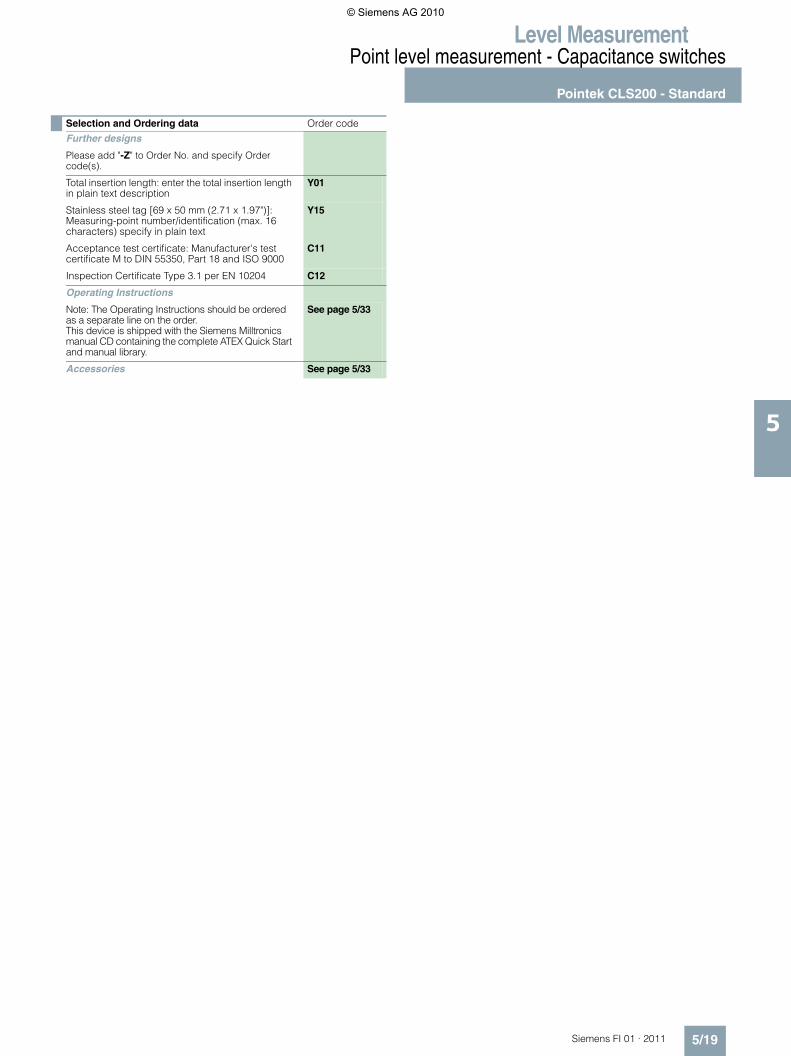
Selection and Ordering data Order code
Further designs
Please add "-Z" to Order No. and specify Order code(s).
Total insertion length: enter the total insertion length in plain text description
Y01
Stainless steel tag [69 x 50 mm (2.71 x 1.97")]: Measuring-point number/identification (max. 16 characters) specify in plain text
Y15
Acceptance test certificate: Manufacturer's test certificate M to DIN 55350, Part 18 and ISO 9000
C11
Inspection Certificate Type 3.1 per EN 10204 C12
Operating Instructions
Note: The Operating Instructions should be ordered as a separate line on the order.This device is shipped with the Siemens Milltronics manual CD containing the complete ATEX Quick Start and manual library.
See page 5/33
Accessories See page 5/33
© Siemens AG 2010
Level MeasurementPoint level measurement - Capacitance switches
Pointek CLS200 - Standard
5/20 Siemens FI 01 · 2011
5
C)Subject to export regulations AL: N, ECCN: EAR99
Selection and Ordering data Order No.Pointek CLS200 - Standard - Cable Version with Threaded or Flanged process connectionVersatile inverse frequency shift capacitance level switch with optional process connection choices and configurable output, ideal for detection of liquids, solids, slurries, foam and interfaces
C) 7 M L 5 6 3 1 -77777 - 777 0
Process ConnectionThreaded, 316L stainless steel¾" NPT [(Taper), ANSI/ASME B1.20.1] 0 A1" NPT [(Taper), ANSI/ASME B1.20.1] 0 B1¼" NPT [(Taper), ANSI/ASME B1.20.1] 0 C1½" NPT [(Taper), ANSI/ASME B1.20.1] 0 DR ¾" [(BSPT), EN 10226/PT (JIS-T), JIS B 0203] 1 AR 1" [(BSPT), EN 10226/PT (JIS-T), JIS B 0203] 1 BR 1½" [(BSPT), EN 10226/PT (JIS-T), JIS B 0203] 1 DG ¾" [(BSPP), EN ISO 228-1/PF (JIS-P), JIS B 0202] 3 AG 1" [(BSPP), EN ISO 228-1/PF (JIS-P), JIS B 0202] 3 BG 1½" [(BSPP), EN ISO 228-1/PF (JIS-P), JIS B 0202] 3 DWelded flange, 316L stainless steel, raised face1" ASME, 150 lb 5 A1" ASME, 300 lb 5 B1" ASME, 600 lb 5 C1½" ASME, 150 lb 5 D1½" ASME, 300 lb 5 E1½" ASME, 600 lb 5 F2" ASME, 150 lb 5 G2" ASME, 300 lb 5 H2" ASME, 600 lb 5 J3" ASME, 150 lb 5 K3" ASME, 300 lb 5 L3" ASME, 600 lb 5 M4" ASME, 150 lb 5 N4" ASME, 300 lb 5 P4" ASME, 600 lb 5 QWelded flange, 316L stainless steel, Type A flat facedDN 25, PN 16 6 ADN 25, PN 40 6 BDN 40, PN 16 6 CDN 40, PN 40 6 DDN 50, PN 16 6 EDN 50, PN 40 6 FDN 80, PN 16 6 GDN 80, PN 40 6 HDN 100, PN 16 6 JDN 100, PN 40 (Note: Flange bolting patterns and facings dimensio-nally correspond to the applicable ASME B16.5 or EN 1092-1 standard.)
6 K
Probe length (length from flange face) (threaded lengths include process thread)Note: No Y01 needed in order code for standard lengthsExtended cable, 3000 mm (118.11"), length can be determined by customer on assembly
A
Extended cable, 6000 mm (236.22"), length can be determined by customer on assembly
B
Add order code Y01 and plain text:"Insertion length ... mm"Extended cable, 500 ... 5000 mm (19.69 ... 196.85")
C
Extended cable, 5001 ... 10000 mm (196.89 ... 393.70")
D
Extended cable, 10001 ... 15000 mm(393.74 ... 590.55")
E
Extended cable, 15001 ... 20000 mm (590.59 ... 787.4")
F
Extended cable, 20001 ... 25000 mm (787.44 ... 984.25")
G
Extended cable, 25001 ... 30000 mm (984.29 ... 1181.1")
H
Thermal IsolatorWithout thermal isolator 0With thermal isolator [for process connection tempe-ratures over +85 °C (+185 °F)]
1
Remote mount electronics and mounting bra-cketWith 2 m (79") of cable 2With 5 m (197") of cable 3Wetted SealsFKM and PTFE 0FFKM and PTFE [for process temperatures above -20 °C (-4 °F)]
1
Probe MaterialFEP jacketed cable with PPS probe body 0FEP jacketed cable with PVDF probe body 1ApprovalsDust Ignition Proof:CE, C-TICK, ATEX II 1/2 D T100 °C
C
Flameproof Enclosure with IS Probe:CE, C-TICK, ATEX II 1 G EEx d[ia] IIC T6...T4,ATEX II 1/2 D T100 °C
D
Flameproof Enclosure with IS Probe, with WHG approval:CE, C-TICK, ATEX II 1/2 G EEx d[ia] IIC T6...T4,ATEX II 1/2 D T100 °C
E
Dust Ignition Proof with IS Probe:CSA/FM Class II, Div. 1, Gr. E, F, G CSA/FM Class III T4
F
Explosion Proof Enclosure with IS Probe:CSA/FM Class I, Div. 1, Gr. A, B, C, DCSA/FM Class II, Div. 1, Gr. E, F, GCSA/FM Class III T4
G
General Purpose (CSA, FM) HGeneral Purpose (CE, C-TICK) JGeneral Purpose (CSA, FM, CE, C-TICK) with WHG approval
K
Enclosure and LidAluminum epoxy coated2 x ½" NPT via adapter - cable inlet, IP65 A2 x M20x1.5 cable inlet, IP65 B2 x ½" NPT via adapter - cable inlet, IP68 C2 x M20x1.5 cable inlet, IP68 D
Selection and Ordering data Order code
Further designs
Please add "-Z" to Order No. and specify Order code(s).
Total insertion length: enter the total insertion length in plain text description
Y01
Stainless steel tag [69 x 50 mm (2.71 x 1.97")]: Measuring-point number/identification (max. 16 cha-racters) specify in plain text
Y15
Acceptance test certificate: Manufacturer's test cer-tificate M to DIN 55350, Part 18 and ISO 9000
C11
Inspection Certificate Type 3.1 per EN 10204 C12
Operating Instructions
Note: The Operating Instructions should be ordered as a separate line on the order.This device is shipped with the Siemens Milltronics manual CD containing the complete ATEX Quick Start and manual library.
See page 5/33
Accessories See page 5/33
Selection and Ordering data Order No.Pointek CLS200 - Standard - Cable Version with Threaded or Flanged process connectionVersatile inverse frequency shift capacitance level switch with optional process connection choices and configurable output, ideal for detection of liquids, solids, slurries, foam and interfaces
C) 7 M L 5 6 3 1 -77777 - 777 0
© Siemens AG 2010
Level MeasurementPoint level measurement - Capacitance switches
Pointek CLS200 - Standard
5/21Siemens FI 01 · 2011
5
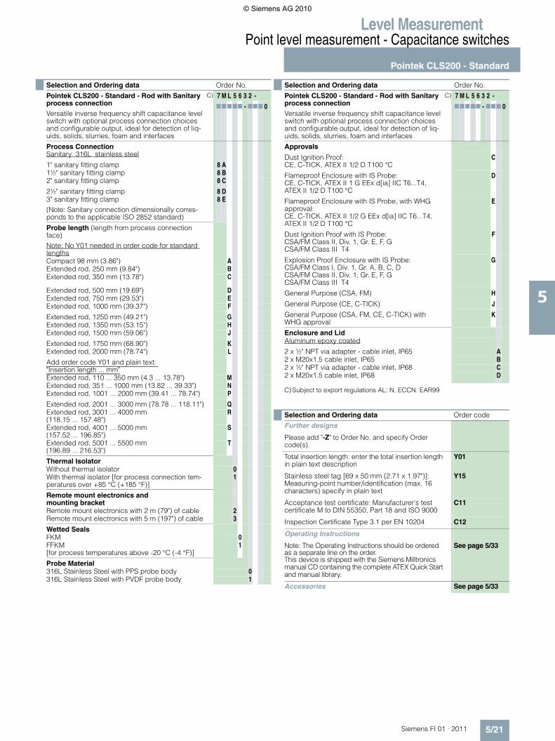
C) Subject to export regulations AL: N, ECCN: EAR99
Selection and Ordering data Order No.
Pointek CLS200 - Standard - Rod with Sanitary process connectionVersatile inverse frequency shift capacitance level switch with optional process connection choices and configurable output, ideal for detection of liq-uids, solids, slurries, foam and interfaces
C) 7 M L 5 6 3 2 -
77777 - 777 0
Process ConnectionSanitary 316L stainless steel
1" sanitary fitting clamp 8 A1½" sanitary fitting clamp 8 B2" sanitary fitting clamp 8 C
2½" sanitary fitting clamp 8 D3" sanitary fitting clamp(Note: Sanitary connection dimensionally corres-ponds to the applicable ISO 2852 standard)
8 E
Probe length (length from process connection face) Note: No Y01 needed in order code for standard lengthsCompact 98 mm (3.86") AExtended rod, 250 mm (9.84") BExtended rod, 350 mm (13.78") C
Extended rod, 500 mm (19.69") DExtended rod, 750 mm (29.53") EExtended rod, 1000 mm (39.37") F
Extended rod, 1250 mm (49.21") GExtended rod, 1350 mm (53.15") HExtended rod, 1500 mm (59.06") J
Extended rod, 1750 mm (68.90") KExtended rod, 2000 mm (78.74") L
Add order code Y01 and plain text: "Insertion length ... mm"Extended rod, 110 ... 350 mm (4.3 ... 13.78") MExtended rod, 351 ... 1000 mm (13.82 ... 39.33") NExtended rod, 1001 ... 2000 mm (39.41 ... 78.74") P
Extended rod, 2001 ... 3000 mm (78.78 ... 118.11") QExtended rod, 3001 ... 4000 mm (118.15 ... 157.48")
R
Extended rod, 4001 ... 5000 mm (157.52 ... 196.85")
S
Extended rod, 5001 ... 5500 mm (196.89 ... 216.53")
T
Thermal IsolatorWithout thermal isolator 0With thermal isolator [for process connection tem-peratures over +85 °C (+185 °F)]
1
Remote mount electronics and mounting bracketRemote mount electronics with 2 m (79") of cable 2Remote mount electronics with 5 m (197") of cable 3
Wetted SealsFKM 0FFKM [for process temperatures above -20 °C (-4 °F)]
1
Probe Material316L Stainless Steel with PPS probe body 0316L Stainless Steel with PVDF probe body 1
Approvals
Dust Ignition Proof:CE, C-TICK, ATEX II 1/2 D T100 °C
C
Flameproof Enclosure with IS Probe:CE, C-TICK, ATEX II 1 G EEx d[ia] IIC T6...T4,ATEX II 1/2 D T100 °C
D
Flameproof Enclosure with IS Probe, with WHG approval:CE, C-TICK, ATEX II 1/2 G EEx d[ia] IIC T6...T4,ATEX II 1/2 D T100 °C
E
Dust Ignition Proof with IS Probe:CSA/FM Class II, Div. 1, Gr. E, F, G CSA/FM Class III T4
F
Explosion Proof Enclosure with IS Probe:CSA/FM Class I, Div. 1, Gr. A, B, C, DCSA/FM Class II, Div. 1, Gr. E, F, GCSA/FM Class III T4
G
General Purpose (CSA, FM) H
General Purpose (CE, C-TICK) J
General Purpose (CSA, FM, CE, C-TICK) with WHG approval
K
Enclosure and LidAluminum epoxy coated
2 x ½" NPT via adapter - cable inlet, IP65 A2 x M20x1.5 cable inlet, IP65 B2 x ½" NPT via adapter - cable inlet, IP68 C2 x M20x1.5 cable inlet, IP68 D
Selection and Ordering data Order code
Further designs
Please add "-Z" to Order No. and specify Order code(s).
Total insertion length: enter the total insertion length in plain text description
Y01
Stainless steel tag [69 x 50 mm (2.71 x 1.97")]: Measuring-point number/identification (max. 16 characters) specify in plain text
Y15
Acceptance test certificate: Manufacturer's test certificate M to DIN 55350, Part 18 and ISO 9000
C11
Inspection Certificate Type 3.1 per EN 10204 C12
Operating Instructions
Note: The Operating Instructions should be ordered as a separate line on the order.This device is shipped with the Siemens Milltronics manual CD containing the complete ATEX Quick Start and manual library.
See page 5/33
Accessories See page 5/33
Selection and Ordering data Order No.
Pointek CLS200 - Standard - Rod with Sanitary process connectionVersatile inverse frequency shift capacitance level switch with optional process connection choices and configurable output, ideal for detection of liq-uids, solids, slurries, foam and interfaces
C) 7 M L 5 6 3 2 -
77777 - 777 0
© Siemens AG 2010
Level MeasurementPoint level measurement - Capacitance switches
Pointek CLS200 - Standard
5/22 Siemens FI 01 · 2011
5
C) Subject to export regulations AL: N, ECCN: EAR99
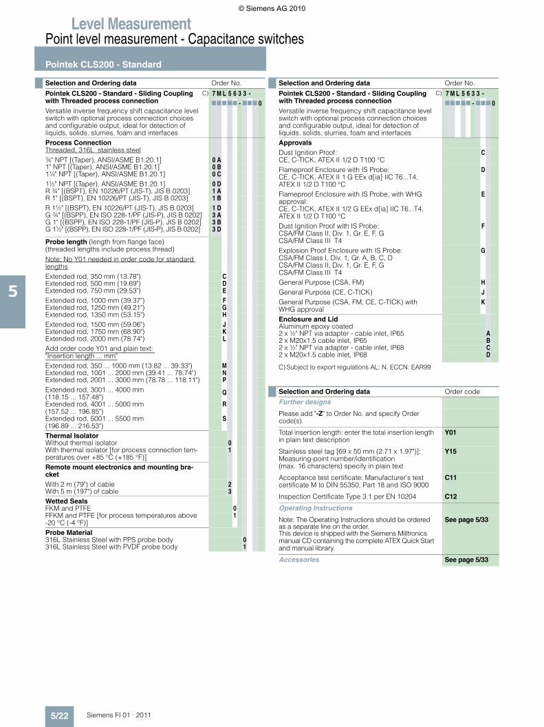
Selection and Ordering data Order No.
Pointek CLS200 - Standard - Sliding Coupling with Threaded process connectionVersatile inverse frequency shift capacitance level switch with optional process connection choices and configurable output, ideal for detection ofliquids, solids, slurries, foam and interfaces
C) 7 M L 5 6 3 3 -77777 - 777 0
Process ConnectionThreaded, 316L stainless steel¾" NPT [(Taper), ANSI/ASME B1.20.1] 0 A1" NPT [(Taper), ANSI/ASME B1.20.1] 0 B1¼" NPT [(Taper), ANSI/ASME B1.20.1] 0 C1½" NPT [(Taper), ANSI/ASME B1.20.1] 0 DR ¾" [(BSPT), EN 10226/PT (JIS-T), JIS B 0203] 1 AR 1" [(BSPT), EN 10226/PT (JIS-T), JIS B 0203] 1 BR 1½" [(BSPT), EN 10226/PT (JIS-T), JIS B 0203] 1 DG ¾" [(BSPP), EN ISO 228-1/PF (JIS-P), JIS B 0202] 3 AG 1" [(BSPP), EN ISO 228-1/PF (JIS-P), JIS B 0202] 3 BG 1½" [(BSPP), EN ISO 228-1/PF (JIS-P), JIS B 0202] 3 D
Probe length (length from flange face) (threaded lengths include process thread)Note: No Y01 needed in order code for standard lengthsExtended rod, 350 mm (13.78") CExtended rod, 500 mm (19.69") DExtended rod, 750 mm (29.53") EExtended rod, 1000 mm (39.37") FExtended rod, 1250 mm (49.21") GExtended rod, 1350 mm (53.15") HExtended rod, 1500 mm (59.06") JExtended rod, 1750 mm (68.90") KExtended rod, 2000 mm (78.74") LAdd order code Y01 and plain text: "Insertion length ... mm"Extended rod, 350 ... 1000 mm (13.82 ... 39.33") MExtended rod, 1001 ... 2000 mm (39.41 ... 78.74") NExtended rod, 2001 ... 3000 mm (78.78 ... 118.11") PExtended rod, 3001 ... 4000 mm (118.15 ... 157.48")
Q
Extended rod, 4001 ... 5000 mm (157.52 ... 196.85")
R
Extended rod, 5001 ... 5500 mm (196.89 ... 216.53")
S
Thermal IsolatorWithout thermal isolator 0With thermal isolator [for process connection tem-peratures over +85 °C (+185 °F)]
1
Remote mount electronics and mounting bra-cketWith 2 m (79") of cable 2With 5 m (197") of cable 3Wetted SealsFKM and PTFE 0FFKM and PTFE [for process temperatures above -20 °C (-4 °F)]
1
Probe Material316L Stainless Steel with PPS probe body 0316L Stainless Steel with PVDF probe body 1
ApprovalsDust Ignition Proof:CE, C-TICK, ATEX II 1/2 D T100 °C
C
Flameproof Enclosure with IS Probe:CE, C-TICK, ATEX II 1 G EEx d[ia] IIC T6...T4,ATEX II 1/2 D T100 °C
D
Flameproof Enclosure with IS Probe, with WHG approval:CE, C-TICK, ATEX II 1/2 G EEx d[ia] IIC T6...T4,ATEX II 1/2 D T100 °C
E
Dust Ignition Proof with IS Probe:CSA/FM Class II, Div. 1, Gr. E, F, G CSA/FM Class III T4
F
Explosion Proof Enclosure with IS Probe:CSA/FM Class I, Div. 1, Gr. A, B, C, DCSA/FM Class II, Div. 1, Gr. E, F, GCSA/FM Class III T4
G
General Purpose (CSA, FM) HGeneral Purpose (CE, C-TICK) JGeneral Purpose (CSA, FM, CE, C-TICK) with WHG approval
K
Enclosure and LidAluminum epoxy coated2 x ½" NPT via adapter - cable inlet, IP65 A2 x M20x1.5 cable inlet, IP65 B2 x ½" NPT via adapter - cable inlet, IP68 C2 x M20x1.5 cable inlet, IP68 D
Selection and Ordering data Order code
Further designs
Please add "-Z" to Order No. and specify Order code(s).
Total insertion length: enter the total insertion length in plain text description
Y01
Stainless steel tag [69 x 50 mm (2.71 x 1.97")]: Measuring-point number/identification(max. 16 characters) specify in plain text
Y15
Acceptance test certificate: Manufacturer's test certificate M to DIN 55350, Part 18 and ISO 9000
C11
Inspection Certificate Type 3.1 per EN 10204 C12
Operating Instructions
Note: The Operating Instructions should be ordered as a separate line on the order.This device is shipped with the Siemens Milltronics manual CD containing the complete ATEX Quick Start and manual library.
See page 5/33
Accessories See page 5/33
Selection and Ordering data Order No.
Pointek CLS200 - Standard - Sliding Coupling with Threaded process connectionVersatile inverse frequency shift capacitance level switch with optional process connection choices and configurable output, ideal for detection ofliquids, solids, slurries, foam and interfaces
C) 7 M L 5 6 3 3 -77777 - 777 0
© Siemens AG 2010
Level MeasurementPoint level measurement - Capacitance switches
Pointek CLS200 - Standard
5/23Siemens FI 01 · 2011
5
C) Subject to export regulations AL: N, ECCN: EAR99
Selection and Ordering data Order No.
Pointek CLS200 - Standard - PFA Coated Rod with PFA Coated Flanged process connectionVersatile inverse frequency shift capacitance level switch with optional rod/cable choices and configu-rable output, ideal for detection of liquids, solids, slurries, foam and interfaces
C) 7 M L 5 6 3 4 -77777 - 777 0
Process ConnectionWelded flange, 316L stainless steel, raised face1" ASME, 150 lb 5 A1" ASME, 300 lb 5 B1" ASME, 600 lb 5 C1½" ASME, 150 lb 5 D1½" ASME, 300 lb 5 E1½" ASME, 600 lb 5 F2" ASME, 150 lb 5 G2" ASME, 300 lb 5 H2" ASME, 600 lb 5 J3" ASME, 150 lb 5 K3" ASME, 300 lb 5 L3" ASME, 600 lb 5 M4" ASME, 150 lb 5 N4" ASME, 300 lb 5 P4" ASME, 600 lb 5 QWelded flange, 316L stainless steel,Type A flat facedDN 25, PN 16 6 ADN 25, PN 40 6 BDN 40, PN 16 6 CDN 40, PN 40 6 DDN 50, PN 16 6 EDN 50, PN 40 6 FDN 80, PN 16 6 GDN 80, PN 40 6 HDN 100, PN 16 6 JDN 100, PN 40 (Note: Flange bolting patterns and facings dimensi-onally correspond to the applicable ASME B16.5 or EN 1092-1 standard.)
6 K
Probe length (length from flange face) (threaded lengths include process thread)Note: No Y01 needed in order code for standard lengthsCompact (Threaded 98 mm (3.86") AExtended rod, 250 mm (9.84") BExtended rod, 350 mm (13.78") C
Extended rod, 500 mm (19.69") DExtended rod, 750 mm (29.53") EExtended rod, 1000 mm (39.37") FExtended rod, 1250 mm (49.21") GExtended rod, 1350 mm (53.15") H
Extended rod, 1500 mm (59.06") JExtended rod, 1750 mm (68.90") KExtended rod, 2000 mm (78.74") LAdd order code Y01 and plain text: "Insertion length ... mm"Extended rod, 200 ... 1000 mm (7.87 ... 39.33") MExtended rod, 1001 ... 2000 mm (39.41 ... 78.74") NExtended rod, 2001 ... 3000 mm (78.78 ... 118.11") PExtended rod, 3001 ... 4000 mm (118.15 ... 157.48")
Q
Extended rod, 4001 ... 5000 mm (157.52 ... 196.85")
R
Extended rod, 5001 ... 5500 mm (196.89 ... 216.53")
S
Thermal IsolatorWithout thermal isolator 0With thermal isolator [for process connection tem-peratures over +85 °C (+185 °F)]
1
Remote mount electronics and mounting bracketWith 2 m (79") of cable 2With 5 m (197") of cable 3
Wetted SealsFKM 0FFKM [for process temperatures above -20°C (-4°F)]
1
Probe MaterialPFA Coated 316L Stainless Steel with PPS probe body
0
PFA Coated 316L Stainless Steel with PVDF probe body
1
ApprovalsDust Ignition Proof with IS Probe:CSA/FM Class II, Div. 1, Gr. E, F, G CSA/FM Class III T4
F
Explosion Proof Enclosure with IS Probe:CSA/FM Class I, Div. 1, Gr. A, B, C, DCSA/FM Class II, Div. 1, Gr. E, F, GCSA/FM Class III T4
G
General Purpose (CSA, FM) HEnclosure and LidAluminum epoxy coated2 x ½" NPT via adapter - cable inlet, IP65 A2 x M20x1.5 cable inlet, IP65 B2 x ½" NPT via adapter - cable inlet, IP68 C2 x M20x1.5 cable inlet, IP68 D
Selection and Ordering data Order code
Further designs
Please add "-Z" to Order No. and specify Order code(s).
Total insertion length: enter the total insertion length in plain text description
Y01
Stainless steel tag [69 x 50 mm (2.71 x 1.97")]: Measuring-point number/identification (max. 16 characters) specify in plain text
Y15
Acceptance test certificate: Manufacturer's test certificate M to DIN 55350, Part 18 and ISO 9000
C11
Inspection Certificate Type 3.1 per EN 10204 C12
Operating Instructions
Note: The Operating Instructions should be ordered as a separate line on the order.This device is shipped with the Siemens Milltronics manual CD containing the complete ATEX Quick Start and manual library.
See page 5/33
Accessories See page 5/33
Selection and Ordering data Order No.
Pointek CLS200 - Standard - PFA Coated Rod with PFA Coated Flanged process connectionVersatile inverse frequency shift capacitance level switch with optional rod/cable choices and configu-rable output, ideal for detection of liquids, solids, slurries, foam and interfaces
C) 7 M L 5 6 3 4 -77777 - 777 0
© Siemens AG 2010
Level MeasurementPoint level measurement - Capacitance switches
Pointek CLS200 - Digital
5/24 Siemens FI 01 · 2011
5
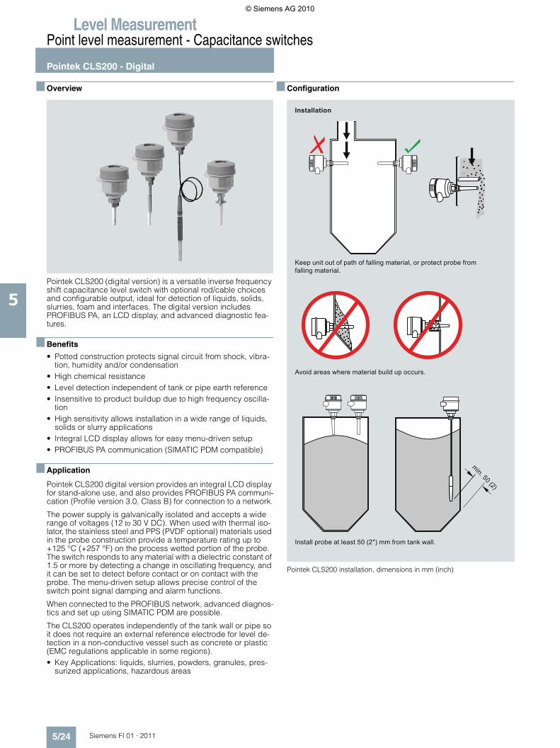
■ Overview
Pointek CLS200 (digital version) is a versatile inverse frequency shift capacitance level switch with optional rod/cable choices and configurable output, ideal for detection of liquids, solids, slurries, foam and interfaces. The digital version includesPROFIBUS PA, an LCD display, and advanced diagnostic fea-tures.
■ Benefits
• Potted construction protects signal circuit from shock, vibra-tion, humidity and/or condensation
• High chemical resistance• Level detection independent of tank or pipe earth reference • Insensitive to product buildup due to high frequency oscilla-
tion• High sensitivity allows installation in a wide range of liquids,
solids or slurry applications• Integral LCD display allows for easy menu-driven setup• PROFIBUS PA communication (SIMATIC PDM compatible)
■ Application
Pointek CLS200 digital version provides an integral LCD display for stand-alone use, and also provides PROFIBUS PA communi-cation (Profile version 3.0, Class B) for connection to a network.
The power supply is galvanically isolated and accepts a wide range of voltages (12 to 30 V DC). When used with thermal iso-lator, the stainless steel and PPS (PVDF optional) materials used in the probe construction provide a temperature rating up to +125 °C (+257 °F) on the process wetted portion of the probe. The switch responds to any material with a dielectric constant of 1.5 or more by detecting a change in oscillating frequency, and it can be set to detect before contact or on contact with the probe. The menu-driven setup allows precise control of the switch point signal damping and alarm functions.
When connected to the PROFIBUS network, advanced diagnos-tics and set up using SIMATIC PDM are possible.
The CLS200 operates independently of the tank wall or pipe so it does not require an external reference electrode for level de-tection in a non-conductive vessel such as concrete or plastic (EMC regulations applicable in some regions).• Key Applications: liquids, slurries, powders, granules, pres-
surized applications, hazardous areas
■ Configuration
Pointek CLS200 installation, dimensions in mm (inch)
Avoid areas where material build up occurs.
Keep unit out of path of falling material, or protect probe from falling material.
Install probe at least 50 (2") mm from tank wall.
Installation
min. 50 (2)
© Siemens AG 2010
Level MeasurementPoint level measurement - Capacitance switches
Pointek CLS200 - Digital
5/25Siemens FI 01 · 2011
5
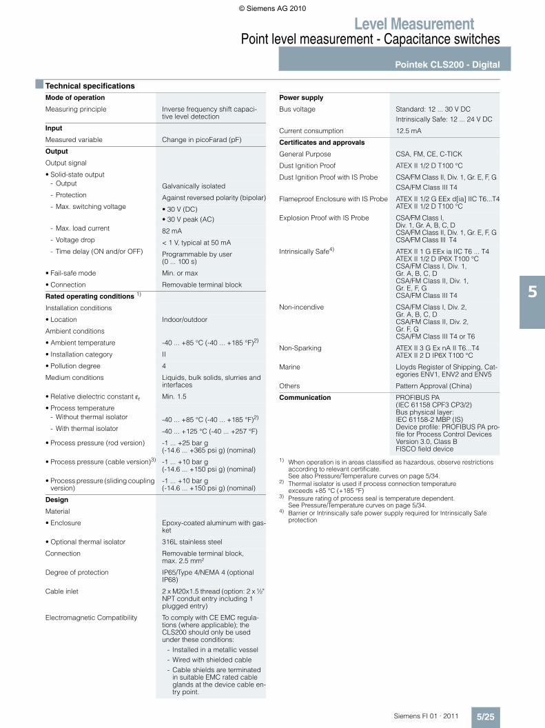
■ Technical specifications
1) When operation is in areas classified as hazardous, observe restrictions according to relevant certificate. See also Pressure/Temperature curves on page 5/34.
2) Thermal isolator is used if process connection temperatureexceeds +85 °C (+185 °F)
3) Pressure rating of process seal is temperature dependent.See Pressure/Temperature curves on page 5/34.
4) Barrier or Intrinsically safe power supply required for Intrinsically Safeprotection
Mode of operation
Measuring principle Inverse frequency shift capaci-tive level detection
Input
Measured variable Change in picoFarad (pF)
Output
Output signal
• Solid-state output - Output Galvanically isolated- Protection Against reversed polarity (bipolar)- Max. switching voltage • 30 V (DC)
• 30 V peak (AC) - Max. load current 82 mA- Voltage drop < 1 V, typical at 50 mA- Time delay (ON and/or OFF) Programmable by user
(0 ... 100 s)
• Fail-safe mode Min. or max
• Connection Removable terminal block
Rated operating conditions 1)
Installation conditions
• Location Indoor/outdoor
Ambient conditions
• Ambient temperature -40 ... +85 °C (-40 ... +185 °F)2)
• Installation category II
• Pollution degree 4
Medium conditions Liquids, bulk solids, slurries and interfaces
• Relative dielectric constant εr Min. 1.5
• Process temperature - Without thermal isolator -40 ... +85 °C (-40 ... +185 °F)2)
- With thermal isolator -40 ... +125 °C (-40 ... +257 °F)
• Process pressure (rod version) -1 ... +25 bar g(-14.6 ... +365 psi g) (nominal)
• Process pressure (cable version)3) -1 ... +10 bar g(-14.6 ... +150 psi g) (nominal)
• Process pressure (sliding coupling version)
-1 ... +10 bar g(-14.6 ... +150 psi g) (nominal)
Design
Material
• Enclosure Epoxy-coated aluminum with gas-ket
• Optional thermal isolator 316L stainless steel
Connection Removable terminal block,max. 2.5 mm²
Degree of protection IP65/Type 4/NEMA 4 (optional IP68)
Cable inlet 2 x M20x1.5 thread (option: 2 x ½" NPT conduit entry including 1 plugged entry)
Electromagnetic Compatibility To comply with CE EMC regula-tions (where applicable); the CLS200 should only be used under these conditions:
- Installed in a metallic vessel - Wired with shielded cable - Cable shields are terminated
in suitable EMC rated cable glands at the device cable en-try point.
Power supply
Bus voltage Standard: 12 ... 30 V DC Intrinsically Safe: 12 ... 24 V DC
Current consumption 12.5 mA
Certificates and approvals
General Purpose CSA, FM, CE, C-TICK
Dust Ignition Proof ATEX II 1/2 D T100 °C
Dust Ignition Proof with IS Probe CSA/FM Class II, Div. 1, Gr. E, F, GCSA/FM Class III T4
Flameproof Enclosure with IS Probe ATEX II 1/2 G EEx d[ia] IIC T6...T4ATEX II 1/2 D T100 °C
Explosion Proof with IS Probe CSA/FM Class I,Div. 1, Gr. A, B, C, DCSA/FM Class II, Div. 1, Gr. E, F, GCSA/FM Class III T4
Intrinsically Safe4) ATEX II 1 G EEx ia IIC T6 ... T4ATEX II 1/2 D IP6X T100 °CCSA/FM Class I, Div. 1,Gr. A, B, C, DCSA/FM Class II, Div. 1,Gr. E, F, GCSA/FM Class III T4
Non-incendive CSA/FM Class I, Div. 2,Gr. A, B, C, DCSA/FM Class II, Div. 2,Gr. F, GCSA/FM Class III T4 or T6
Non-Sparking ATEX II 3 G Ex nA II T6...T4ATEX II 2 D IP6X T100 °C
Marine Lloyds Register of Shipping, Cat-egories ENV1, ENV2 and ENV5
Others Pattern Approval (China)
Communication PROFIBUS PA (IEC 61158 CPF3 CP3/2) Bus physical layer: IEC 61158-2 MBP (IS) Device profile: PROFIBUS PA pro-file for Process Control Devices Version 3.0, Class B FISCO field device
© Siemens AG 2010
Level MeasurementPoint level measurement - Capacitance switches
Pointek CLS200 - Digital
5/26 Siemens FI 01 · 2011
5
1) PFA coating (7ML5634 and 7ML5644) has 120 micron thickness2) For Caustic Materials please contact [email protected] for alternative O-rings3) Thermal isolator is used if process connection temperature exceeds +85 °C (+185 °F).
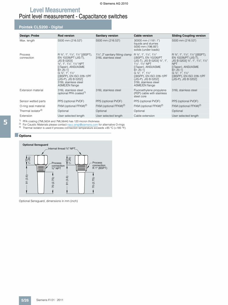
■ Options
Optional Sensguard, dimensions in mm (inch)
Design: Probe Rod version Sanitary version Cable version Sliding Coupling version
Max. length 5500 mm (216.53") 5500 mm (216.53") 30000 mm (1181.1") liquids and slurries 5000 mm (196.85") solids (under loads)
5500 mm (216.53")
Process connection
R ¾", 1", 1¼", 1½" [(BSPT),EN 10226/PT (JIS-T), JIS B 0203]¾", 1", 1¼", 1½" NPT [(Taper), ANSI/ASME B1.20.1]G ¾", 1", 1½" [(BSPP), EN ISO 228-1/PF (JIS-P), JIS B 0202]316L stainless steelASME/EN flange
1½", 2" sanitary fitting clamp 316L stainless steel
R ¾", 1", 1¼", 1½"[(BSPT), EN 10226/PT(JIS-T), JIS B 0203] ¾", 1", 1¼", 1½" NPT[(Taper), ANSI/ASME B1.20.1]G ¾", 1", 1½"[(BSPP), EN ISO 228-1/PF (JIS-P), JIS B 0202]316L stainless steel ASME/EN flange
R ¾", 1", 1¼", 1½" [(BSPT),EN 10226/PT (JIS-T), JIS B 0203] ¾", 1", 1¼", 1½" NPT [(Taper), ANSI/ASME B1.20.1]G ¾", 1", 1½"[(BSPP), EN ISO 228-1/PF (JIS-P), JIS B 0202]
Extension material 316L stainless steeloptional PFA coated1)
316L stainless steel Fluoroethylene propylene (FEP) cable with stainless steel core
316L stainless steel
Sensor wetted parts PPS (optional PVDF) PPS (optional PVDF) PPS (optional PVDF) PPS (optional PVDF)
O-ring seal material FKM (optional FFKM)2) FKM (optional FFKM)2) FKM (optional FFKM)2) FKM (optional FFKM)2)
Thermal isolator3) Optional Optional Optional Optional
Extension User selected length User selected length Cable extension User selected length
Optional SensguardInternal thread ¾" NPT
Processconnection ¾" NPT
ProcessconnectionR 1" (BSPT)
32(1
.26)
70 (2
.75)
70 (2
.75)
91 (3
.6)
91 (3
.6)
32(1
.26)
© Siemens AG 2010
Level MeasurementPoint level measurement - Capacitance switches
Pointek CLS200 - Digital
5/27Siemens FI 01 · 2011
5
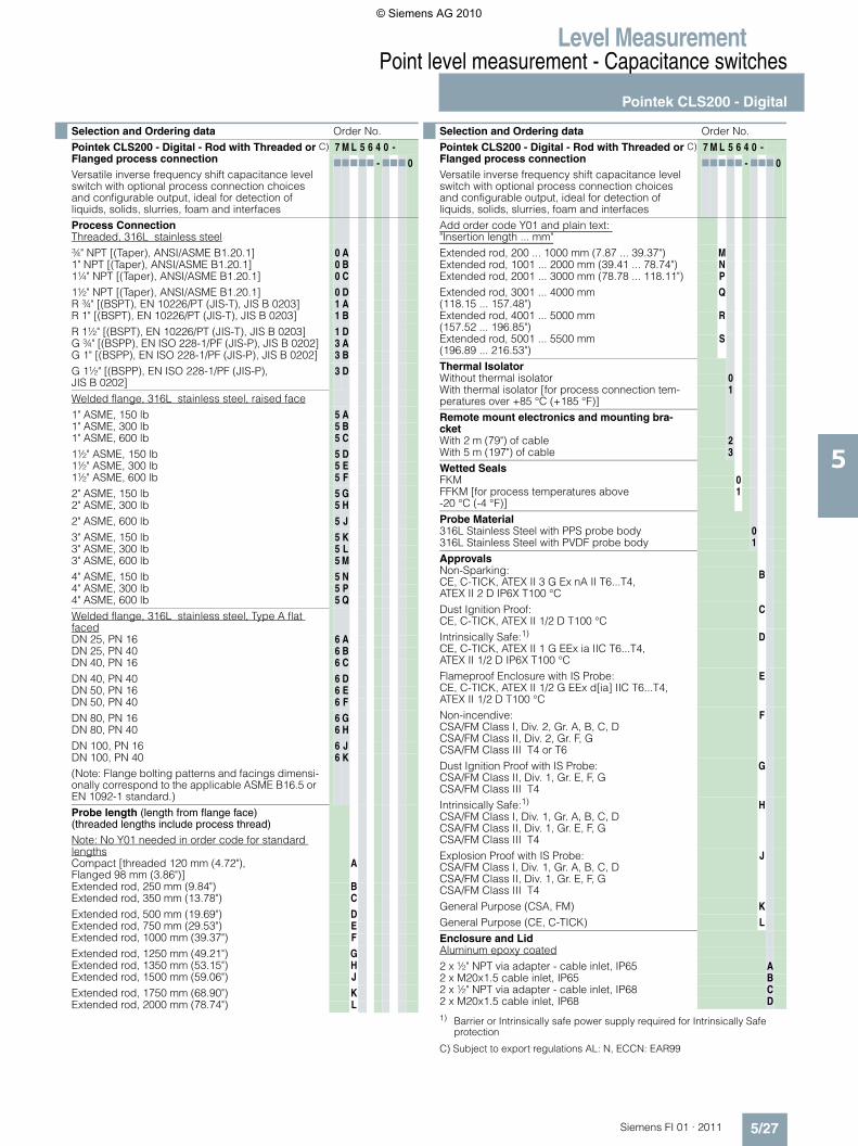
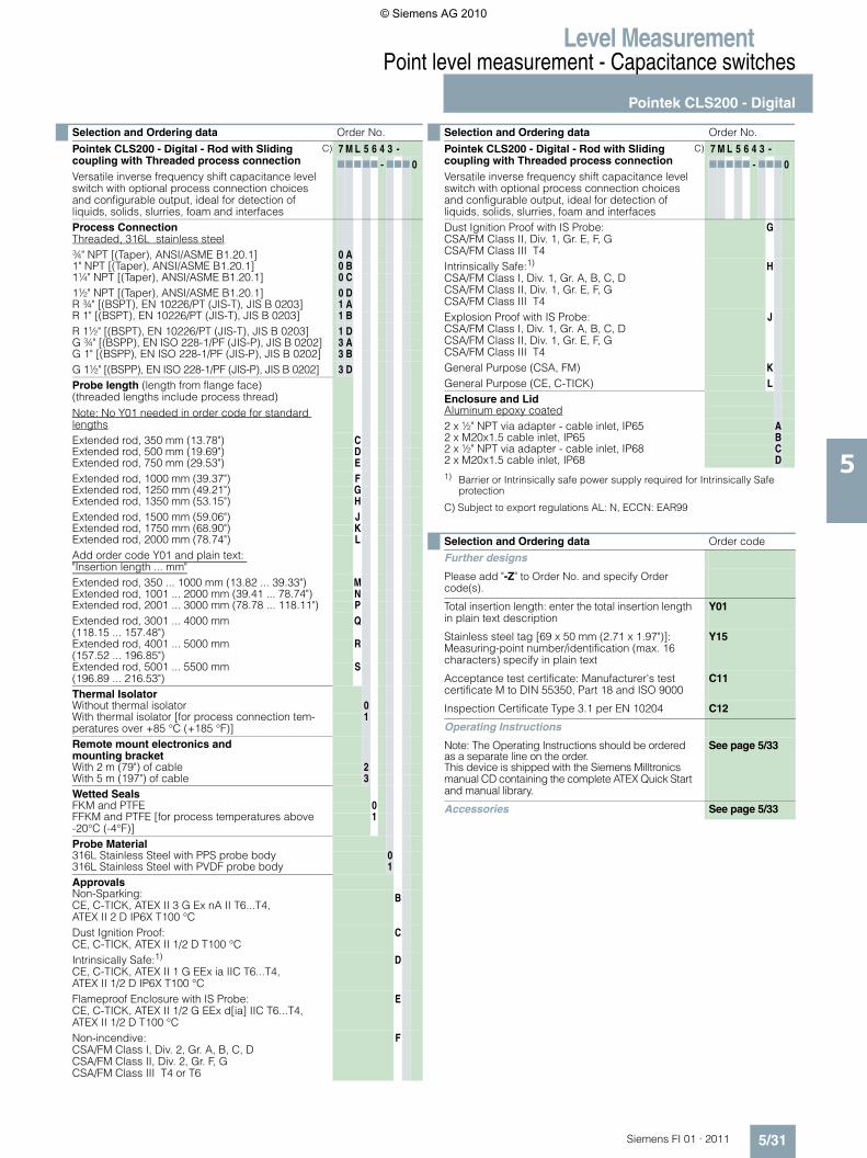
C) Subject to export regulations AL: N, ECCN: EAR99
Selection and Ordering data Order No.Pointek CLS200 - Digital - Rod with Threaded or Flanged process connectionVersatile inverse frequency shift capacitance level switch with optional process connection choices and configurable output, ideal for detection of liquids, solids, slurries, foam and interfaces
C) 7 M L 5 6 4 0 -77777 - 777 0
Process ConnectionThreaded, 316L stainless steel¾" NPT [(Taper), ANSI/ASME B1.20.1] 0 A1" NPT [(Taper), ANSI/ASME B1.20.1] 0 B1¼" NPT [(Taper), ANSI/ASME B1.20.1] 0 C
1½" NPT [(Taper), ANSI/ASME B1.20.1] 0 DR ¾" [(BSPT), EN 10226/PT (JIS-T), JIS B 0203] 1 AR 1" [(BSPT), EN 10226/PT (JIS-T), JIS B 0203] 1 B
R 1½" [(BSPT), EN 10226/PT (JIS-T), JIS B 0203] 1 DG ¾" [(BSPP), EN ISO 228-1/PF (JIS-P), JIS B 0202] 3 AG 1" [(BSPP), EN ISO 228-1/PF (JIS-P), JIS B 0202] 3 B
G 1½" [(BSPP), EN ISO 228-1/PF (JIS-P), JIS B 0202]
3 D
Welded flange, 316L stainless steel, raised face1" ASME, 150 lb 5 A1" ASME, 300 lb 5 B1" ASME, 600 lb 5 C
1½" ASME, 150 lb 5 D1½" ASME, 300 lb 5 E1½" ASME, 600 lb 5 F
2" ASME, 150 lb 5 G2" ASME, 300 lb 5 H
2" ASME, 600 lb 5 J
3" ASME, 150 lb 5 K3" ASME, 300 lb 5 L3" ASME, 600 lb 5 M
4" ASME, 150 lb 5 N4" ASME, 300 lb 5 P4" ASME, 600 lb 5 Q
Welded flange, 316L stainless steel, Type A flat facedDN 25, PN 16 6 ADN 25, PN 40 6 BDN 40, PN 16 6 C
DN 40, PN 40 6 DDN 50, PN 16 6 EDN 50, PN 40 6 F
DN 80, PN 16 6 GDN 80, PN 40 6 H
DN 100, PN 16 6 JDN 100, PN 40 (Note: Flange bolting patterns and facings dimensi-onally correspond to the applicable ASME B16.5 or EN 1092-1 standard.)
6 K
Probe length (length from flange face) (threaded lengths include process thread)
Note: No Y01 needed in order code for standard lengthsCompact [threaded 120 mm (4.72"),Flanged 98 mm (3.86")]
A
Extended rod, 250 mm (9.84") BExtended rod, 350 mm (13.78") C
Extended rod, 500 mm (19.69") DExtended rod, 750 mm (29.53") EExtended rod, 1000 mm (39.37") F
Extended rod, 1250 mm (49.21") GExtended rod, 1350 mm (53.15") HExtended rod, 1500 mm (59.06") J
Extended rod, 1750 mm (68.90") KExtended rod, 2000 mm (78.74") L
Add order code Y01 and plain text: "Insertion length ... mm"Extended rod, 200 ... 1000 mm (7.87 ... 39.37") MExtended rod, 1001 ... 2000 mm (39.41 ... 78.74") NExtended rod, 2001 ... 3000 mm (78.78 ... 118.11") P
Extended rod, 3001 ... 4000 mm (118.15 ... 157.48")
Q
Extended rod, 4001 ... 5000 mm (157.52 ... 196.85")
R
Extended rod, 5001 ... 5500 mm (196.89 ... 216.53")
S
Thermal IsolatorWithout thermal isolator 0With thermal isolator [for process connection tem-peratures over +85 °C (+185 °F)]
1
Remote mount electronics and mounting bra-cketWith 2 m (79") of cable 2With 5 m (197") of cable 3
Wetted SealsFKM 0FFKM [for process temperatures above-20 °C (-4 °F)]
1
Probe Material316L Stainless Steel with PPS probe body 0316L Stainless Steel with PVDF probe body 1
ApprovalsNon-Sparking:CE, C-TICK, ATEX II 3 G Ex nA II T6...T4,ATEX II 2 D IP6X T100 °C
B
Dust Ignition Proof:CE, C-TICK, ATEX II 1/2 D T100 °C
C
Intrinsically Safe:1)
CE, C-TICK, ATEX II 1 G EEx ia IIC T6...T4, ATEX II 1/2 D IP6X T100 °C
D
Flameproof Enclosure with IS Probe:CE, C-TICK, ATEX II 1/2 G EEx d[ia] IIC T6...T4,ATEX II 1/2 D T100 °C
E
Non-incendive:CSA/FM Class I, Div. 2, Gr. A, B, C, DCSA/FM Class II, Div. 2, Gr. F, GCSA/FM Class III T4 or T6
F
Dust Ignition Proof with IS Probe:CSA/FM Class II, Div. 1, Gr. E, F, GCSA/FM Class III T4
G
Intrinsically Safe:1)
CSA/FM Class I, Div. 1, Gr. A, B, C, DCSA/FM Class II, Div. 1, Gr. E, F, GCSA/FM Class III T4
H
Explosion Proof with IS Probe:CSA/FM Class I, Div. 1, Gr. A, B, C, DCSA/FM Class II, Div. 1, Gr. E, F, GCSA/FM Class III T4
J
General Purpose (CSA, FM) K
General Purpose (CE, C-TICK) L
Enclosure and LidAluminum epoxy coated2 x ½" NPT via adapter - cable inlet, IP65 A2 x M20x1.5 cable inlet, IP65 B2 x ½" NPT via adapter - cable inlet, IP68 C2 x M20x1.5 cable inlet, IP68 D
1) Barrier or Intrinsically safe power supply required for Intrinsically Safeprotection
Selection and Ordering data Order No.Pointek CLS200 - Digital - Rod with Threaded or Flanged process connectionVersatile inverse frequency shift capacitance level switch with optional process connection choices and configurable output, ideal for detection of liquids, solids, slurries, foam and interfaces
C) 7 M L 5 6 4 0 -77777 - 777 0
© Siemens AG 2010
Level MeasurementPoint level measurement - Capacitance switches
Pointek CLS200 - Digital
5/28 Siemens FI 01 · 2011
5
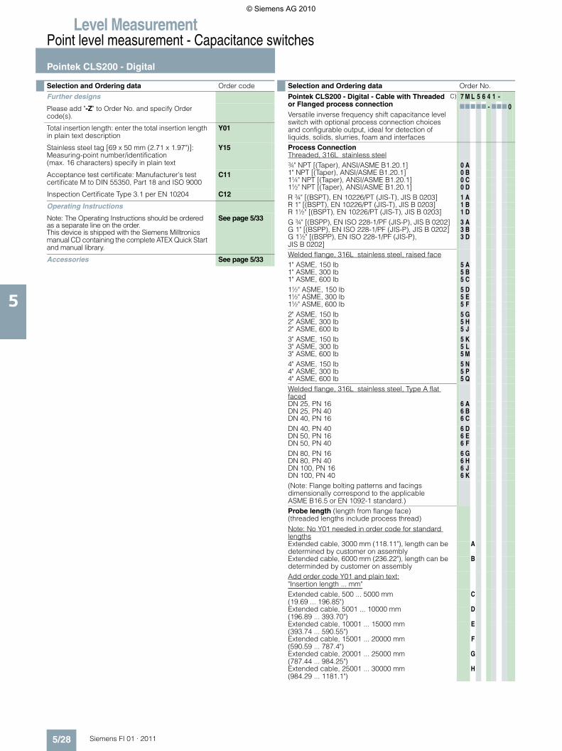
Selection and Ordering data Order code
Further designs
Please add "-Z" to Order No. and specify Order code(s).
Total insertion length: enter the total insertion length in plain text description
Y01
Stainless steel tag [69 x 50 mm (2.71 x 1.97")]: Measuring-point number/identification(max. 16 characters) specify in plain text
Y15
Acceptance test certificate: Manufacturer's test certificate M to DIN 55350, Part 18 and ISO 9000
C11
Inspection Certificate Type 3.1 per EN 10204 C12
Operating Instructions
Note: The Operating Instructions should be ordered as a separate line on the order.This device is shipped with the Siemens Milltronics manual CD containing the complete ATEX Quick Start and manual library.
See page 5/33
Accessories See page 5/33
Selection and Ordering data Order No.
Pointek CLS200 - Digital - Cable with Threaded or Flanged process connectionVersatile inverse frequency shift capacitance level switch with optional process connection choices and configurable output, ideal for detection ofliquids, solids, slurries, foam and interfaces
C) 7 M L 5 6 4 1 -77777 - 777 0
Process ConnectionThreaded, 316L stainless steel¾" NPT [(Taper), ANSI/ASME B1.20.1] 0 A1" NPT [(Taper), ANSI/ASME B1.20.1] 0 B1¼" NPT [(Taper), ANSI/ASME B1.20.1] 0 C1½" NPT [(Taper), ANSI/ASME B1.20.1] 0 DR ¾" [(BSPT), EN 10226/PT (JIS-T), JIS B 0203] 1 AR 1" [(BSPT), EN 10226/PT (JIS-T), JIS B 0203] 1 BR 1½" [(BSPT), EN 10226/PT (JIS-T), JIS B 0203] 1 DG ¾" [(BSPP), EN ISO 228-1/PF (JIS-P), JIS B 0202] 3 AG 1" [(BSPP), EN ISO 228-1/PF (JIS-P), JIS B 0202] 3 BG 1½" [(BSPP), EN ISO 228-1/PF (JIS-P), JIS B 0202]
3 D
Welded flange, 316L stainless steel, raised face1" ASME, 150 lb 5 A1" ASME, 300 lb 5 B1" ASME, 600 lb 5 C1½" ASME, 150 lb 5 D1½" ASME, 300 lb 5 E1½" ASME, 600 lb 5 F2" ASME, 150 lb 5 G2" ASME, 300 lb 5 H2" ASME, 600 lb 5 J3" ASME, 150 lb 5 K3" ASME, 300 lb 5 L3" ASME, 600 lb 5 M4" ASME, 150 lb 5 N4" ASME, 300 lb 5 P4" ASME, 600 lb 5 QWelded flange, 316L stainless steel, Type A flat facedDN 25, PN 16 6 ADN 25, PN 40 6 BDN 40, PN 16 6 CDN 40, PN 40 6 DDN 50, PN 16 6 EDN 50, PN 40 6 FDN 80, PN 16 6 GDN 80, PN 40 6 HDN 100, PN 16 6 JDN 100, PN 40 6 K(Note: Flange bolting patterns and facings dimensionally correspond to the applicable ASME B16.5 or EN 1092-1 standard.) Probe length (length from flange face) (threaded lengths include process thread)Note: No Y01 needed in order code for standard lengthsExtended cable, 3000 mm (118.11"), length can be determined by customer on assembly
A
Extended cable, 6000 mm (236.22"), length can be determinded by customer on assembly
B
Add order code Y01 and plain text:"Insertion length ... mm"Extended cable, 500 ... 5000 mm (19.69 ... 196.85")
C
Extended cable, 5001 ... 10000 mm(196.89 ... 393.70")
D
Extended cable, 10001 ... 15000 mm(393.74 ... 590.55")
E
Extended cable, 15001 ... 20000 mm(590.59 ... 787.4")
F
Extended cable, 20001 ... 25000 mm(787.44 ... 984.25")
G
Extended cable, 25001 ... 30000 mm(984.29 ... 1181.1")
H
© Siemens AG 2010
Level MeasurementPoint level measurement - Capacitance switches
Pointek CLS200 - Digital
5/29Siemens FI 01 · 2011
5
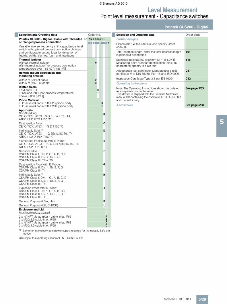
C) Subject to export regulations AL: N, ECCN: EAR99
Thermal IsolatorWithout thermal isolator 0With thermal isolator [for process connection temperatures over +85 °C (+185 °F)]
1
Remote mount electronics and mounting bracketWith 2 m (79") of cable 2With 5 m (197") of cable 3Wetted SealsFKM and PTFE 0FFKM and PTFE [for process temperatures above -20°C (-4°F)]
1
Probe MaterialFEP jacketed cable with PPS probe body 0FEP jacketed cable with PVDF probe body 1ApprovalsNon-Sparking:CE, C-TICK, ATEX II 3 G Ex nA II T6...T4,ATEX II 2 D IP6X T100 °C
B
Dust Ignition Proof:CE, C-TICK, ATEX II 1/2 D T100 °C
C
Intrinsically Safe:1)
CE, C-TICK, ATEX II 1 G EEx ia IIC T6...T4, ATEX II 1/2 D IP6X T100 °C
D
Flameproof Enclosure with IS Probe:CE, C-TICK, ATEX II 1/2 G EEx d[ia] IIC T6...T4,ATEX II 1/2 D T100 °C
E
Non-incendive:CSA/FM Class I, Div. 2, Gr. A, B, C, DCSA/FM Class II, Div. 2, Gr. F, GCSA/FM Class III T4 or T6
F
Dust Ignition Proof with IS Probe:CSA/FM Class II, Div. 1, Gr. E, F, GCSA/FM Class III T4
G
Intrinsically Safe:1)
CSA/FM Class I, Div. 1, Gr. A, B, C, DCSA/FM Class II, Div. 1, Gr. E, F, GCSA/FM Class III T4
H
Explosion Proof with IS Probe:CSA/FM Class I, Div. 1, Gr. A, B, C, DCSA/FM Class II, Div. 1, Gr. E, F, GCSA/FM Class III T4
J
General Purpose (CSA, FM) KGeneral Purpose (CE, C-TICK) LEnclosure and LidAluminum epoxy coated2 x ½" NPT via adapter - cable inlet, IP65 A2 x M20x1.5 cable inlet, IP65 B2 x ½" NPT via adapter - cable inlet, IP68 C2 x M20x1.5 cable inlet, IP68 D1) Barrier or Intrinsically safe power supply required for Intrinsically Safe pro-
tection
Selection and Ordering data Order No.
Pointek CLS200 - Digital - Cable with Threaded or Flanged process connectionVersatile inverse frequency shift capacitance level switch with optional process connection choices and configurable output, ideal for detection ofliquids, solids, slurries, foam and interfaces
C) 7 M L 5 6 4 1 -77777 - 777 0
Selection and Ordering data Order code
Further designs
Please add "-Z" to Order No. and specify Order code(s).
Total insertion length: enter the total insertion length in plain text description
Y01
Stainless steel tag [69 x 50 mm (2.71 x 1.97")]: Measuring-point number/identification (max. 16 characters) specify in plain text
Y15
Acceptance test certificate: Manufacturer's test certificate M to DIN 55350, Part 18 and ISO 9000
C11
Inspection Certificate Type 3.1 per EN 10204 C12
Operating Instructions
Note: The Operating Instructions should be ordered as a separate line on the order.This device is shipped with the Siemens Milltronics manual CD containing the complete ATEX Quick Start and manual library.
See page 5/33
Accessories See page 5/33
© Siemens AG 2010
Level MeasurementPoint level measurement - Capacitance switches
Pointek CLS200 - Digital
5/30 Siemens FI 01 · 2011
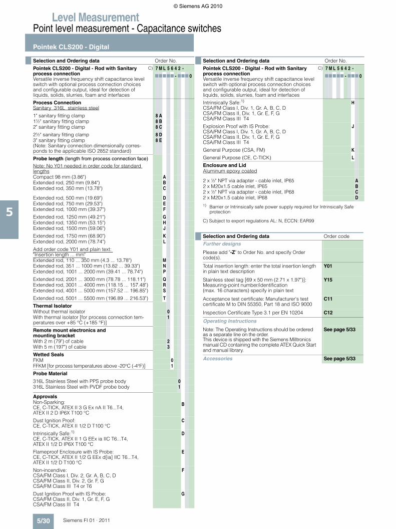
5C) Subject to export regulations AL: N, ECCN: EAR99
Selection and Ordering data Order No.
Pointek CLS200 - Digital - Rod with Sanitary process connectionVersatile inverse frequency shift capacitance level switch with optional process connection choices and configurable output, ideal for detection of liquids, solids, slurries, foam and interfaces
C) 7 M L 5 6 4 2 -
77777 - 777 0
Process ConnectionSanitary 316L stainless steel
1" sanitary fitting clamp 8 A1½" sanitary fitting clamp 8 B2" sanitary fitting clamp 8 C
2½" sanitary fitting clamp 8 D3" sanitary fitting clamp(Note: Sanitary connection dimensionally corres-ponds to the applicable ISO 2852 standard)
8 E
Probe length (length from process connection face)
Note: No Y01 needed in order code for standard lengthsCompact 98 mm (3.86") AExtended rod, 250 mm (9.84") BExtended rod, 350 mm (13.78") C
Extended rod, 500 mm (19.69") DExtended rod, 750 mm (29.53") EExtended rod, 1000 mm (39.37") F
Extended rod, 1250 mm (49.21") GExtended rod, 1350 mm (53.15") HExtended rod, 1500 mm (59.06") J
Extended rod, 1750 mm (68.90") KExtended rod, 2000 mm (78.74") L
Add order code Y01 and plain text: "Insertion length ... mm"Extended rod, 110 ... 350 mm (4.3 ... 13.78") MExtended rod, 351 ... 1000 mm (13.82 ... 39.33") NExtended rod, 1001 ... 2000 mm (39.41 ... 78.74") P
Extended rod, 2001 ... 3000 mm (78.78 ... 118.11") QExtended rod, 3001 ... 4000 mm (118.15 ... 157.48") RExtended rod, 4001 ... 5000 mm (157.52 ... 196.85") S
Extended rod, 5001 ... 5500 mm (196.89 ... 216.53") T
Thermal IsolatorWithout thermal isolator 0With thermal isolator [for process connection tem-peratures over +85 °C (+185 °F)]
1
Remote mount electronics and mounting bracketWith 2 m (79") of cable 2With 5 m (197") of cable 3
Wetted SealsFKM 0FFKM [for process temperatures above -20°C (-4°F)] 1
Probe Material
316L Stainless Steel with PPS probe body 0316L Stainless Steel with PVDF probe body 1
ApprovalsNon-Sparking:CE, C-TICK, ATEX II 3 G Ex nA II T6...T4,ATEX II 2 D IP6X T100 °C
B
Dust Ignition Proof:CE, C-TICK, ATEX II 1/2 D T100 °C
C
Intrinsically Safe:1)
CE, C-TICK, ATEX II 1 G EEx ia IIC T6...T4, ATEX II 1/2 D IP6X T100 °C
D
Flameproof Enclosure with IS Probe:CE, C-TICK, ATEX II 1/2 G EEx d[ia] IIC T6...T4,ATEX II 1/2 D T100 °C
E
Non-incendive:CSA/FM Class I, Div. 2, Gr. A, B, C, DCSA/FM Class II, Div. 2, Gr. F, GCSA/FM Class III T4 or T6
F
Dust Ignition Proof with IS Probe:CSA/FM Class II, Div. 1, Gr. E, F, GCSA/FM Class III T4
G
Intrinsically Safe:1)
CSA/FM Class I, Div. 1, Gr. A, B, C, DCSA/FM Class II, Div. 1, Gr. E, F, GCSA/FM Class III T4
H
Explosion Proof with IS Probe:CSA/FM Class I, Div. 1, Gr. A, B, C, DCSA/FM Class II, Div. 1, Gr. E, F, GCSA/FM Class III T4
J
General Purpose (CSA, FM) K
General Purpose (CE, C-TICK) L
Enclosure and LidAluminum epoxy coated
2 x ½" NPT via adapter - cable inlet, IP65 A2 x M20x1.5 cable inlet, IP65 B2 x ½" NPT via adapter - cable inlet, IP68 C2 x M20x1.5 cable inlet, IP68 D
1) Barrier or Intrinsically safe power supply required for Intrinsically Safeprotection
Selection and Ordering data Order code
Further designs
Please add "-Z" to Order No. and specify Order code(s).
Total insertion length: enter the total insertion length in plain text description
Y01
Stainless steel tag [69 x 50 mm (2.71 x 1.97")]: Measuring-point number/identification(max. 16 characters) specify in plain text
Y15
Acceptance test certificate: Manufacturer's test certificate M to DIN 55350, Part 18 and ISO 9000
C11
Inspection Certificate Type 3.1 per EN 10204 C12
Operating Instructions
Note: The Operating Instructions should be ordered as a separate line on the order.This device is shipped with the Siemens Milltronics manual CD containing the complete ATEX Quick Start and manual library.
See page 5/33
Accessories See page 5/33
Selection and Ordering data Order No.
Pointek CLS200 - Digital - Rod with Sanitary process connectionVersatile inverse frequency shift capacitance level switch with optional process connection choices and configurable output, ideal for detection of liquids, solids, slurries, foam and interfaces
C) 7 M L 5 6 4 2 -
77777 - 777 0
© Siemens AG 2010
Level MeasurementPoint level measurement - Capacitance switches
Pointek CLS200 - Digital
5/31Siemens FI 01 · 2011
5
C) Subject to export regulations AL: N, ECCN: EAR99
Selection and Ordering data Order No.
Pointek CLS200 - Digital - Rod with Sliding coupling with Threaded process connectionVersatile inverse frequency shift capacitance level switch with optional process connection choices and configurable output, ideal for detection of liquids, solids, slurries, foam and interfaces
C) 7 M L 5 6 4 3 -77777 - 777 0
Process ConnectionThreaded, 316L stainless steel¾" NPT [(Taper), ANSI/ASME B1.20.1] 0 A1" NPT [(Taper), ANSI/ASME B1.20.1] 0 B1¼" NPT [(Taper), ANSI/ASME B1.20.1] 0 C1½" NPT [(Taper), ANSI/ASME B1.20.1] 0 DR ¾" [(BSPT), EN 10226/PT (JIS-T), JIS B 0203] 1 AR 1" [(BSPT), EN 10226/PT (JIS-T), JIS B 0203] 1 BR 1½" [(BSPT), EN 10226/PT (JIS-T), JIS B 0203] 1 DG ¾" [(BSPP), EN ISO 228-1/PF (JIS-P), JIS B 0202] 3 AG 1" [(BSPP), EN ISO 228-1/PF (JIS-P), JIS B 0202] 3 BG 1½" [(BSPP), EN ISO 228-1/PF (JIS-P), JIS B 0202] 3 DProbe length (length from flange face) (threaded lengths include process thread)Note: No Y01 needed in order code for standard lengthsExtended rod, 350 mm (13.78") CExtended rod, 500 mm (19.69") DExtended rod, 750 mm (29.53") EExtended rod, 1000 mm (39.37") FExtended rod, 1250 mm (49.21") GExtended rod, 1350 mm (53.15") HExtended rod, 1500 mm (59.06") JExtended rod, 1750 mm (68.90") KExtended rod, 2000 mm (78.74") LAdd order code Y01 and plain text: "Insertion length ... mm"Extended rod, 350 ... 1000 mm (13.82 ... 39.33") MExtended rod, 1001 ... 2000 mm (39.41 ... 78.74") NExtended rod, 2001 ... 3000 mm (78.78 ... 118.11") PExtended rod, 3001 ... 4000 mm (118.15 ... 157.48")
Q
Extended rod, 4001 ... 5000 mm (157.52 ... 196.85")
R
Extended rod, 5001 ... 5500 mm (196.89 ... 216.53")
S
Thermal IsolatorWithout thermal isolator 0With thermal isolator [for process connection tem-peratures over +85 °C (+185 °F)]
1
Remote mount electronics and mounting bracketWith 2 m (79") of cable 2With 5 m (197") of cable 3Wetted SealsFKM and PTFE 0FFKM and PTFE [for process temperatures above -20°C (-4°F)]
1
Probe Material316L Stainless Steel with PPS probe body 0316L Stainless Steel with PVDF probe body 1ApprovalsNon-Sparking:CE, C-TICK, ATEX II 3 G Ex nA II T6...T4,ATEX II 2 D IP6X T100 °C
B
Dust Ignition Proof:CE, C-TICK, ATEX II 1/2 D T100 °C
C
Intrinsically Safe:1)
CE, C-TICK, ATEX II 1 G EEx ia IIC T6...T4, ATEX II 1/2 D IP6X T100 °C
D
Flameproof Enclosure with IS Probe:CE, C-TICK, ATEX II 1/2 G EEx d[ia] IIC T6...T4,ATEX II 1/2 D T100 °C
E
Non-incendive:CSA/FM Class I, Div. 2, Gr. A, B, C, DCSA/FM Class II, Div. 2, Gr. F, GCSA/FM Class III T4 or T6
F
Dust Ignition Proof with IS Probe:CSA/FM Class II, Div. 1, Gr. E, F, GCSA/FM Class III T4
G
Intrinsically Safe:1)
CSA/FM Class I, Div. 1, Gr. A, B, C, DCSA/FM Class II, Div. 1, Gr. E, F, GCSA/FM Class III T4
H
Explosion Proof with IS Probe:CSA/FM Class I, Div. 1, Gr. A, B, C, DCSA/FM Class II, Div. 1, Gr. E, F, GCSA/FM Class III T4
J
General Purpose (CSA, FM) KGeneral Purpose (CE, C-TICK) LEnclosure and LidAluminum epoxy coated2 x ½" NPT via adapter - cable inlet, IP65 A2 x M20x1.5 cable inlet, IP65 B2 x ½" NPT via adapter - cable inlet, IP68 C2 x M20x1.5 cable inlet, IP68 D1) Barrier or Intrinsically safe power supply required for Intrinsically Safe
protection
Selection and Ordering data Order code
Further designs
Please add "-Z" to Order No. and specify Order code(s).
Total insertion length: enter the total insertion length in plain text description
Y01
Stainless steel tag [69 x 50 mm (2.71 x 1.97")]: Measuring-point number/identification (max. 16 characters) specify in plain text
Y15
Acceptance test certificate: Manufacturer's test certificate M to DIN 55350, Part 18 and ISO 9000
C11
Inspection Certificate Type 3.1 per EN 10204 C12
Operating Instructions
Note: The Operating Instructions should be ordered as a separate line on the order.This device is shipped with the Siemens Milltronics manual CD containing the complete ATEX Quick Start and manual library.
See page 5/33
Accessories See page 5/33
Selection and Ordering data Order No.
Pointek CLS200 - Digital - Rod with Sliding coupling with Threaded process connectionVersatile inverse frequency shift capacitance level switch with optional process connection choices and configurable output, ideal for detection of liquids, solids, slurries, foam and interfaces
C) 7 M L 5 6 4 3 -77777 - 777 0
© Siemens AG 2010
Level MeasurementPoint level measurement - Capacitance switches
Pointek CLS200 - Digital
5/32 Siemens FI 01 · 2011
5
1) Barrier or Intrinsically safe power supply required for Intrinsically Safe pro-tection
C) Subject to export regulations AL: N, ECCN: EAR99
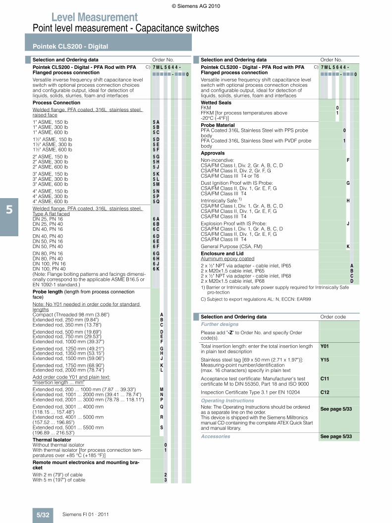
Selection and Ordering data Order No.
Pointek CLS200 - Digital - PFA Rod with PFA Flanged process connectionVersatile inverse frequency shift capacitance level switch with optional process connection choices and configurable output, ideal for detection of liquids, solids, slurries, foam and interfaces
C) 7 M L 5 6 4 4 -77777 - 777 0
Process ConnectionWelded flange, PFA coated, 316L stainless steel, raised face1" ASME, 150 lb 5 A1" ASME, 300 lb 5 B1" ASME, 600 lb 5 C1½" ASME, 150 lb 5 D1½" ASME, 300 lb 5 E1½" ASME, 600 lb 5 F2" ASME, 150 lb 5 G2" ASME, 300 lb 5 H2" ASME, 600 lb 5 J3" ASME, 150 lb 5 K3" ASME, 300 lb 5 L3" ASME, 600 lb 5 M4" ASME, 150 lb 5 N4" ASME, 300 lb 5 P4" ASME, 600 lb 5 QWelded flange, PFA coated, 316L stainless steel, Type A flat facedDN 25, PN 16 6 ADN 25, PN 40 6 BDN 40, PN 16 6 CDN 40, PN 40 6 DDN 50, PN 16 6 EDN 50, PN 40 6 FDN 80, PN 16 6 GDN 80, PN 40 6 HDN 100, PN 16 6 JDN 100, PN 40 (Note: Flange bolting patterns and facings dimensi-onally correspond to the applicable ASME B16.5 or EN 1092-1 standard.)
6 K
Probe length (length from process connection face)
Note: No Y01 needed in order code for standard lengthsCompact (Threaded 98 mm (3.86") AExtended rod, 250 mm (9.84") BExtended rod, 350 mm (13.78") CExtended rod, 500 mm (19.69") DExtended rod, 750 mm (29.53") EExtended rod, 1000 mm (39.37") FExtended rod, 1250 mm (49.21") GExtended rod, 1350 mm (53.15") HExtended rod, 1500 mm (59.06") JExtended rod, 1750 mm (68.90") KExtended rod, 2000 mm (78.74") LAdd order code Y01 and plain text:"Insertion length ... mm"Extended rod, 200 ... 1000 mm (7.87 ... 39.33") MExtended rod, 1001 ... 2000 mm (39.41 ... 78.74") NExtended rod, 2001 ... 3000 mm (78.78 ... 118.11") PExtended rod, 3001 ... 4000 mm (118.15 ... 157.48")
Q
Extended rod, 4001 ... 5000 mm (157.52 ... 196.85")
R
Extended rod, 5001 ... 5500 mm (196.89 ... 216.53")
S
Thermal IsolatorWithout thermal isolator 0With thermal isolator [for process connection tem-peratures over +85 °C (+185 °F)]
1
Remote mount electronics and mounting bra-cketWith 2 m (79") of cable 2With 5 m (197") of cable 3
Wetted SealsFKM 0FFKM [for process temperatures above -20°C (-4°F)]
1
Probe MaterialPFA Coated 316L Stainless Steel with PPS probe body
0
PFA Coated 316L Stainless Steel with PVDF probe body
1
ApprovalsNon-incendive:CSA/FM Class I, Div. 2, Gr. A, B, C, DCSA/FM Class II, Div. 2, Gr. F, GCSA/FM Class III T4 or T6
F
Dust Ignition Proof with IS Probe:CSA/FM Class II, Div. 1, Gr. E, F, GCSA/FM Class III T4
G
Intrinsically Safe:1)
CSA/FM Class I, Div. 1, Gr. A, B, C, DCSA/FM Class II, Div. 1, Gr. E, F, GCSA/FM Class III T4
H
Explosion Proof with IS Probe:CSA/FM Class I, Div. 1, Gr. A, B, C, DCSA/FM Class II, Div. 1, Gr. E, F, GCSA/FM Class III T4
J
General Purpose (CSA, FM) KEnclosure and LidAluminum epoxy coated2 x ½" NPT via adapter - cable inlet, IP65 A2 x M20x1.5 cable inlet, IP65 B2 x ½" NPT via adapter - cable inlet, IP68 C2 x M20x1.5 cable inlet, IP68 D
Selection and Ordering data Order code
Further designs
Please add "-Z" to Order No. and specify Order code(s).
Total insertion length: enter the total insertion length in plain text description
Y01
Stainless steel tag [69 x 50 mm (2.71 x 1.97")]: Measuring-point number/identification(max. 16 characters) specify in plain text
Y15
Acceptance test certificate: Manufacturer's test certificate M to DIN 55350, Part 18 and ISO 9000
C11
Inspection Certificate Type 3.1 per EN 10204 C12
Operating InstructionsNote: The Operating Instructions should be ordered as a separate line on the order.This device is shipped with the Siemens Milltronics manual CD containing the complete ATEX Quick Start and manual library.
See page 5/33
Accessories See page 5/33
Selection and Ordering data Order No.
Pointek CLS200 - Digital - PFA Rod with PFA Flanged process connectionVersatile inverse frequency shift capacitance level switch with optional process connection choices and configurable output, ideal for detection of liquids, solids, slurries, foam and interfaces
C) 7 M L 5 6 4 4 -77777 - 777 0
© Siemens AG 2010
Level MeasurementPoint level measurement - Capacitance switches
Pointek CLS200 - Standard and Digital
5/33Siemens FI 01 · 2011
5
C) Subject to export regulations AL: N, ECCN: EAR99
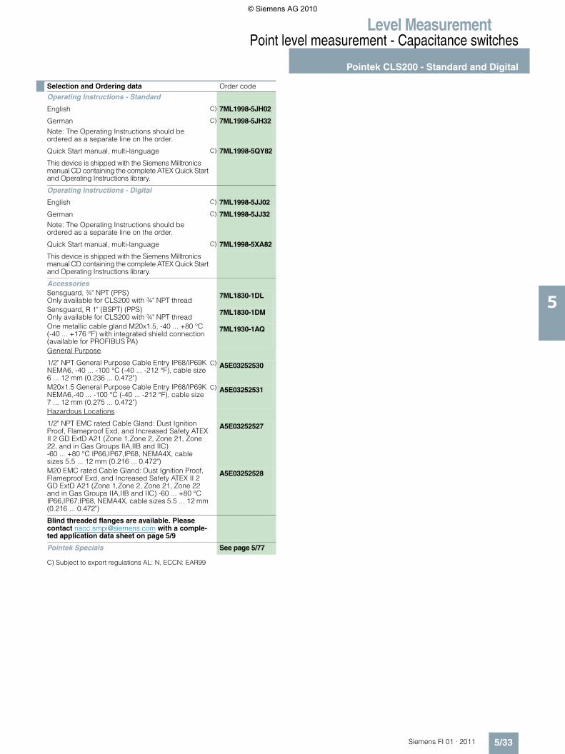
Selection and Ordering data Order code
Operating Instructions - Standard
English C) 7ML1998-5JH02
German Note: The Operating Instructions should be ordered as a separate line on the order.
C) 7ML1998-5JH32
Quick Start manual, multi-language C) 7ML1998-5QY82
This device is shipped with the Siemens Milltronics manual CD containing the complete ATEX Quick Start and Operating Instructions library.
Operating Instructions - Digital
English C) 7ML1998-5JJ02
German Note: The Operating Instructions should be ordered as a separate line on the order.
C) 7ML1998-5JJ32
Quick Start manual, multi-language C) 7ML1998-5XA82
This device is shipped with the Siemens Milltronics manual CD containing the complete ATEX Quick Start and Operating Instructions library.
AccessoriesSensguard, ¾" NPT (PPS)Only available for CLS200 with ¾" NPT thread
7ML1830-1DL
Sensguard, R 1" (BSPT) (PPS)Only available for CLS200 with ¾" NPT thread
7ML1830-1DM
One metallic cable gland M20x1.5, -40 ... +80 °C(-40 ... +176 °F) with integrated shield connection (available for PROFIBUS PA)
7ML1930-1AQ
General Purpose
1/2" NPT General Purpose Cable Entry IP68/IP69K NEMA6, -40 ... -100 °C (-40 ... -212 °F), cable size 6 ... 12 mm (0.236 ... 0.472")
C) A5E03252530
M20x1.5 General Purpose Cable Entry IP68/IP69K NEMA6,-40 ... -100 °C (-40 ... -212 °F), cable size7 ... 12 mm (0.275 ... 0.472")
C) A5E03252531
Hazardous Locations
1/2" NPT EMC rated Cable Gland: Dust Ignition Proof, Flameproof Exd, and Increased Safety ATEX II 2 GD ExtD A21 (Zone 1,Zone 2, Zone 21, Zone 22, and in Gas Groups IIA,IIB and IIC) -60 ... +80 °C IP66,IP67,IP68, NEMA4X, cable sizes 5.5 ... 12 mm (0.216 ... 0.472")
A5E03252527
M20 EMC rated Cable Gland: Dust Ignition Proof, Flameproof Exd, and Increased Safety ATEX II 2 GD ExtD A21 (Zone 1,Zone 2, Zone 21, Zone 22 and in Gas Groups IIA,IIB and IIC) -60 ... +80 °C IP66,IP67,IP68, NEMA4X, cable sizes 5.5 ... 12 mm (0.216 ... 0.472")
A5E03252528
Blind threaded flanges are available. Please contact [email protected] with a comple-ted application data sheet on page 5/9
Pointek Specials See page 5/77
© Siemens AG 2010
Level MeasurementPoint level measurement - Capacitance switches
Pointek CLS200 - Standard and Digital
5/34 Siemens FI 01 · 2011
5
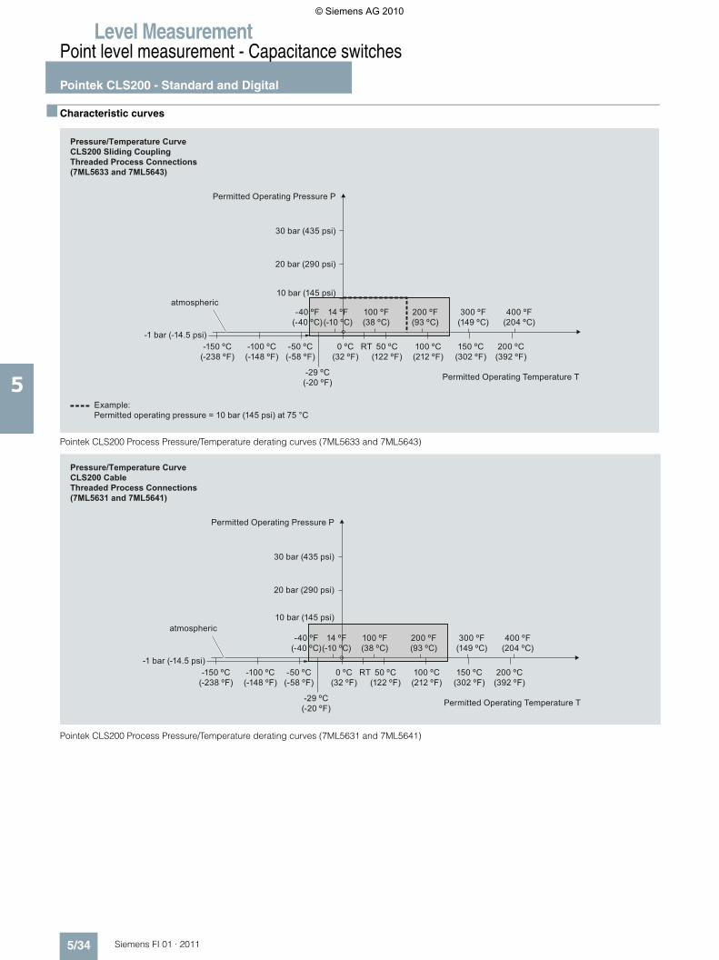
■ Characteristic curves
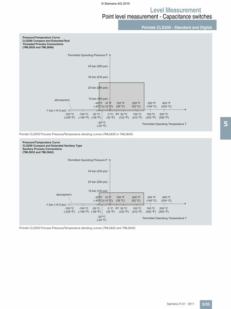
Pointek CLS200 Process Pressure/Temperature derating curves (7ML5633 and 7ML5643)
Pointek CLS200 Process Pressure/Temperature derating curves (7ML5631 and 7ML5641)
Example:Permitted operating pressure = 10 bar (145 psi) at 75 °C
Permitted Operating Pressure P
Permitted Operating Temperature T
atmospheric
Pressure/Temperature CurveCLS200 Sliding CouplingThreaded Process Connections(7ML5633 and 7ML5643)
30 bar (435 psi)
20 bar (290 psi)
10 bar (145 psi)
-150 ºC (-238 ºF)
-1 bar (-14.5 psi)-100 ºC (-148 ºF)
-50 ºC (-58 ºF)
-29 ºC (-20 ºF)
0 ºC (32 ºF)
50 ºC (122 ºF)
RT 100 ºC (212 ºF)
150 ºC (302 ºF)
200 ºC (392 ºF)
-40 ºF(-40 ºC)
400 ºF(204 ºC)
300 ºF(149 ºC)
200 ºF(93 ºC)
100 ºF(38 ºC)
14 ºF(-10 ºC)
Permitted Operating Pressure P
Permitted Operating Temperature T
atmospheric
Pressure/Temperature CurveCLS200 CableThreaded Process Connections(7ML5631 and 7ML5641)
30 bar (435 psi)
20 bar (290 psi)
10 bar (145 psi)
-150 ºC (-238 ºF)
-1 bar (-14.5 psi)-100 ºC (-148 ºF)
-50 ºC (-58 ºF)
-29 ºC (-20 ºF)
0 ºC (32 ºF)
50 ºC (122 ºF)
RT 100 ºC (212 ºF)
150 ºC (302 ºF)
200 ºC (392 ºF)
-40 ºF(-40 ºC)
400 ºF(204 ºC)
300 ºF(149 ºC)
200 ºF(93 ºC)
100 ºF(38 ºC)
14 ºF(-10 ºC)
© Siemens AG 2010
Level MeasurementPoint level measurement - Capacitance switches
Pointek CLS200 - Standard and Digital
5/35Siemens FI 01 · 2011
5Pointek CLS200 Process Pressure/Temperature derating curves (7ML5630 or 7ML5640)
Pointek CLS200 Process Pressure/Temperature derating curves (7ML5632 and 7ML5642)
Permitted Operating Pressure P
Permitted Operating Temperature T
atmospheric
Pressure/Temperature CurveCLS200 Compact and Extended RodThreaded Process Connections(7ML5630 and 7ML5640)
30 bar (435 psi)
20 bar (290 psi)
40 bar (580 psi)
10 bar (145 psi)
-150 ºC (-238 ºF)
-1 bar (-14.5 psi)-100 ºC (-148 ºF)
-50 ºC (-58 ºF)
-29 ºC (-20 ºF)
0 ºC (32 ºF)
50 ºC (122 ºF)
RT 100 ºC (212 ºF)
150 ºC (302 ºF)
200 ºC (392 ºF)
-40 ºF(-40 ºC)
400 ºF(204 ºC)
300 ºF(149 ºC)
200 ºF(93 ºC)
100 ºF(38 ºC)
14 ºF(-10 ºC)
Permitted Operating Pressure P
Permitted Operating Temperature T
Pressure/Temperature CurveCLS200 Compact and Extended Sanitary TypeSanitary Process Connections(7ML5632 and 7ML5642)
atmospheric
30 bar (435 psi)
20 bar (290 psi)
10 bar (145 psi)
-150 ºC (-238 ºF)
-1 bar (-14.5 psi)-100 ºC (-148 ºF)
-50 ºC (-58 ºF)
-29 ºC (-20 ºF)
0 ºC (32 ºF)
50 ºC (122 ºF)
RT 100 ºC (212 ºF)
150 ºC (302 ºF)
200 ºC (392 ºF)
-40 ºF(-40 ºC)
400 ºF(204 ºC)
300 ºF(149 ºC)
200 ºF(93 ºC)
100 ºF(38 ºC)
14 ºF(-10 ºC)
© Siemens AG 2010
Level MeasurementPoint level measurement - Capacitance switches
Pointek CLS200 - Standard and Digital
5/36 Siemens FI 01 · 2011
5
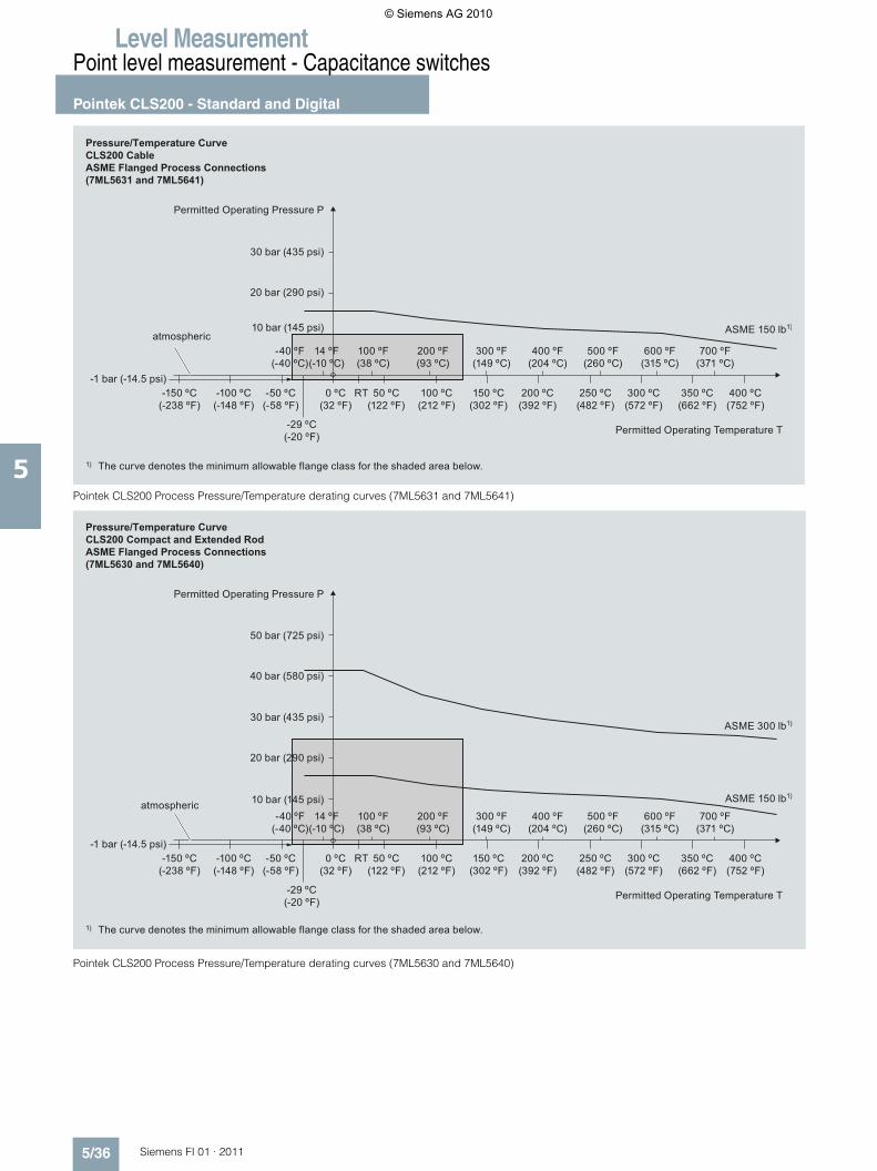
Pointek CLS200 Process Pressure/Temperature derating curves (7ML5631 and 7ML5641)
Pointek CLS200 Process Pressure/Temperature derating curves (7ML5630 and 7ML5640)
The curve denotes the minimum allowable flange class for the shaded area below.1)
Permitted Operating Pressure P
Permitted Operating Temperature T
Pressure/Temperature CurveCLS200 CableASME Flanged Process Connections(7ML5631 and 7ML5641)
atmospheric
30 bar (435 psi)
20 bar (290 psi)
10 bar (145 psi)
-150 ºC (-238 ºF)
-1 bar (-14.5 psi)-100 ºC (-148 ºF)
-50 ºC (-58 ºF)
-29 ºC (-20 ºF)
0 ºC (32 ºF)
50 ºC (122 ºF)
RT 100 ºC (212 ºF)
150 ºC (302 ºF)
200 ºC (392 ºF)
250 ºC (482 ºF)
300 ºC (572 ºF)
350 ºC (662 ºF)
400 ºC (752 ºF)
-40 ºF(-40 ºC)
700 ºF(371 ºC)
600 ºF(315 ºC)
500 ºF(260 ºC)
400 ºF(204 ºC)
300 ºF(149 ºC)
200 ºF(93 ºC)
100 ºF(38 ºC)
14 ºF(-10 ºC)
ASME 150 lb1)
The curve denotes the minimum allowable flange class for the shaded area below.1)
Permitted Operating Pressure P
Permitted Operating Temperature T
Pressure/Temperature CurveCLS200 Compact and Extended RodASME Flanged Process Connections (7ML5630 and 7ML5640)
atmospheric
30 bar (435 psi)
20 bar (290 psi)
50 bar (725 psi)
40 bar (580 psi)
10 bar (145 psi)
-150 ºC (-238 ºF)
-1 bar (-14.5 psi)-100 ºC (-148 ºF)
-50 ºC (-58 ºF)
-29 ºC (-20 ºF)
0 ºC (32 ºF)
50 ºC (122 ºF)
RT 100 ºC (212 ºF)
150 ºC (302 ºF)
200 ºC (392 ºF)
250 ºC (482 ºF)
300 ºC (572 ºF)
350 ºC (662 ºF)
400 ºC (752 ºF)
-40 ºF(-40 ºC)
700 ºF(371 ºC)
600 ºF(315 ºC)
500 ºF(260 ºC)
400 ºF(204 ºC)
300 ºF(149 ºC)
200 ºF(93 ºC)
100 ºF(38 ºC)
14 ºF(-10 ºC)
ASME 150 lb1)
ASME 300 lb1)
© Siemens AG 2010
Level MeasurementPoint level measurement - Capacitance switches
Pointek CLS200 - Standard and Digital
5/37Siemens FI 01 · 2011
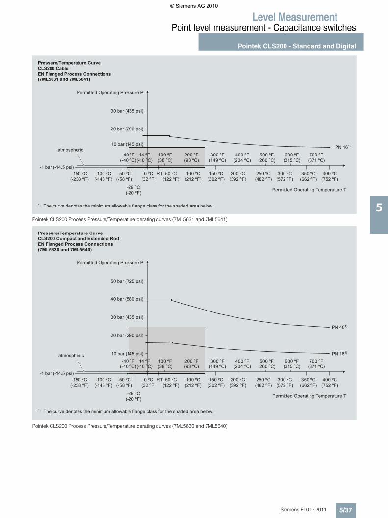
5Pointek CLS200 Process Pressure/Temperature derating curves (7ML5631 and 7ML5641)
Pointek CLS200 Process Pressure/Temperature derating curves (7ML5630 and 7ML5640)
The curve denotes the minimum allowable flange class for the shaded area below.1)
Permitted Operating Pressure P
Permitted Operating Temperature T
Pressure/Temperature CurveCLS200 CableEN Flanged Process Connections(7ML5631 and 7ML5641)
atmospheric
30 bar (435 psi)
20 bar (290 psi)
10 bar (145 psi)
-150 ºC (-238 ºF)
-1 bar (-14.5 psi)-100 ºC (-148 ºF)
-50 ºC (-58 ºF)
-29 ºC (-20 ºF)
0 ºC (32 ºF)
50 ºC (122 ºF)
RT 100 ºC (212 ºF)
150 ºC (302 ºF)
200 ºC (392 ºF)
250 ºC (482 ºF)
300 ºC (572 ºF)
350 ºC (662 ºF)
400 ºC (752 ºF)
-40 ºF(-40 ºC)
700 ºF(371 ºC)
600 ºF(315 ºC)
500 ºF(260 ºC)
400 ºF(204 ºC)
300 ºF(149 ºC)
200 ºF(93 ºC)
100 ºF(38 ºC)
14 ºF(-10 ºC)
PN 161)
The curve denotes the minimum allowable flange class for the shaded area below.1)
Permitted Operating Pressure P
Permitted Operating Temperature T
Pressure/Temperature CurveCLS200 Compact and Extended RodEN Flanged Process Connections (7ML5630 and 7ML5640)
atmospheric
30 bar (435 psi)
20 bar (290 psi)
50 bar (725 psi)
40 bar (580 psi)
10 bar (145 psi)
-150 ºC (-238 ºF)
-1 bar (-14.5 psi)-100 ºC (-148 ºF)
-50 ºC (-58 ºF)
-29 ºC (-20 ºF)
0 ºC (32 ºF)
50 ºC (122 ºF)
RT 100 ºC (212 ºF)
150 ºC (302 ºF)
200 ºC (392 ºF)
250 ºC (482 ºF)
300 ºC (572 ºF)
350 ºC (662 ºF)
400 ºC (752 ºF)
-40 ºF(-40 ºC)
700 ºF(371 ºC)
600 ºF(315 ºC)
500 ºF(260 ºC)
400 ºF(204 ºC)
300 ºF(149 ºC)
200 ºF(93 ºC)
100 ºF(38 ºC)
14 ºF(-10 ºC)
PN 401)
PN 161)
© Siemens AG 2010
Level MeasurementPoint level measurement - Capacitance switches
Pointek CLS200 - Standard and Digital
5/38 Siemens FI 01 · 2011
5
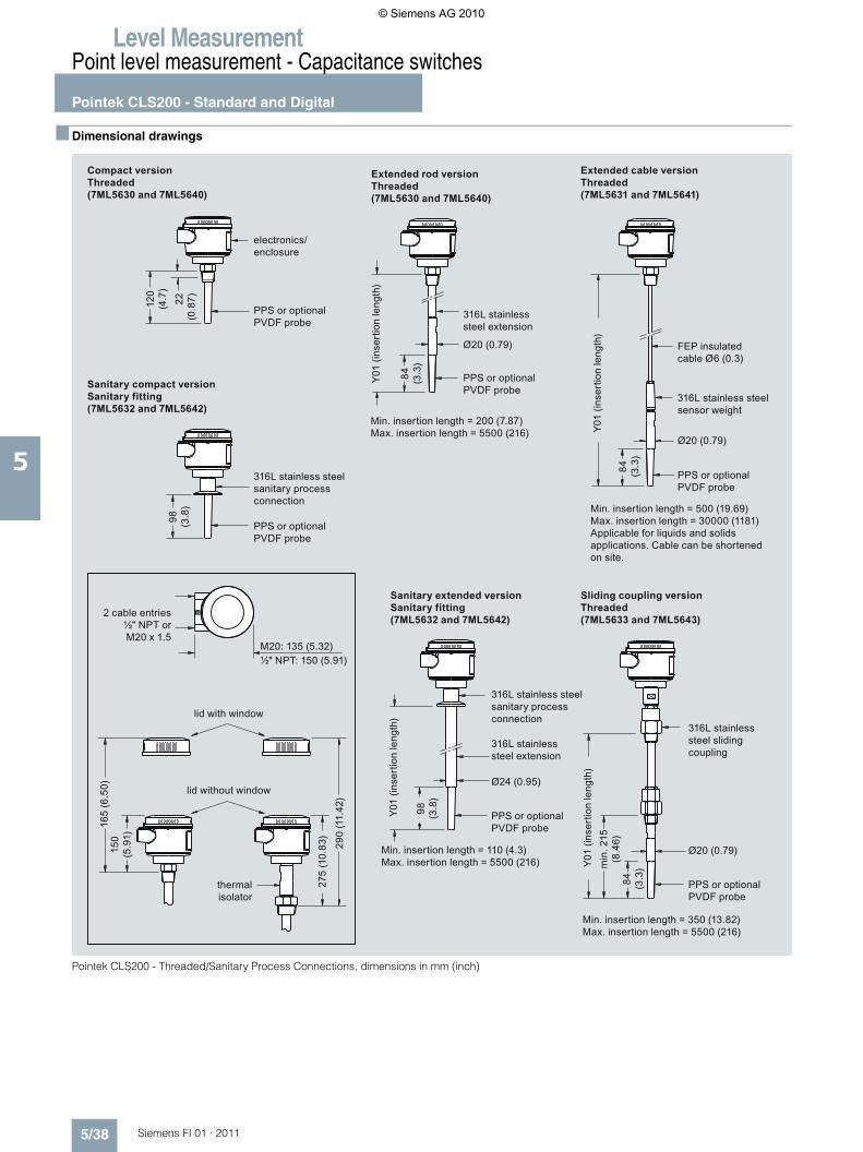
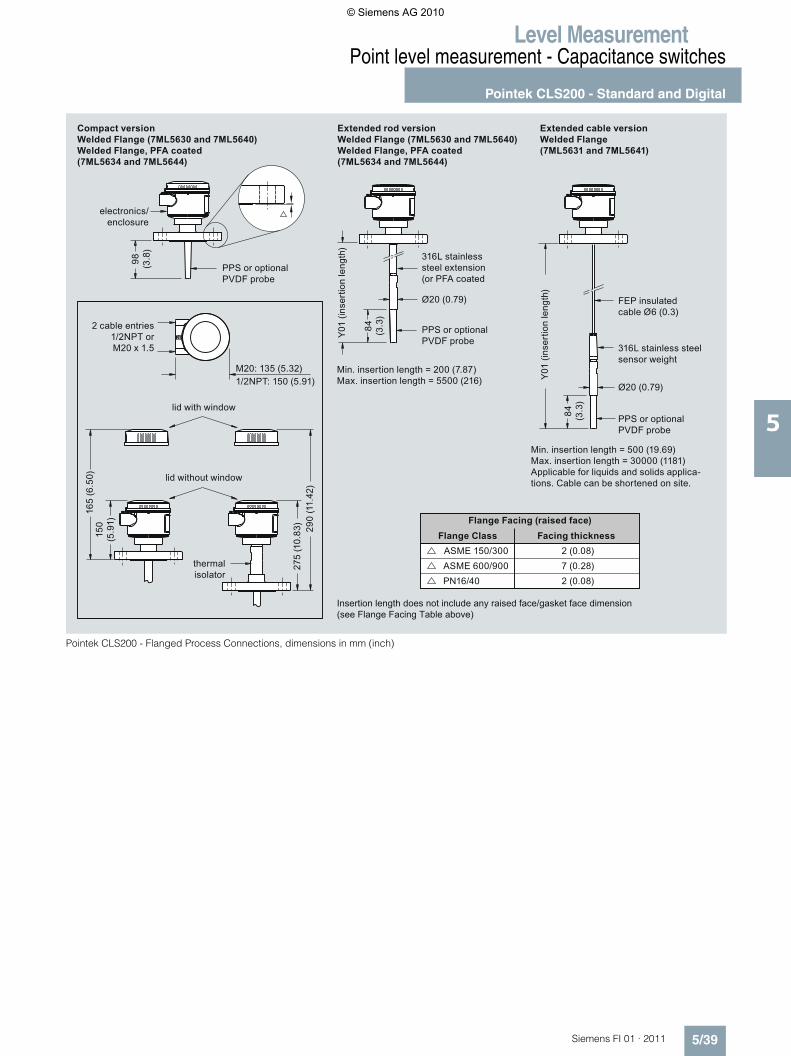
■ Dimensional drawings
Pointek CLS200 - Threaded/Sanitary Process Connections, dimensions in mm (inch)
thermalisolator
316L stainless steel sanitary process connection
Sanitary compact versionSanitary fitting (7ML5632 and 7ML5642)
Min. insertion length = 500 (19.69)Max. insertion length = 30000 (1181)Applicable for liquids and solids applications. Cable can be shortened on site.
Min. insertion length = 200 (7.87)Max. insertion length = 5500 (216)
Min. insertion length = 110 (4.3)Max. insertion length = 5500 (216)
FEP insulated cable Ø6 (0.3)
316L stainless steel sensor weight
316L stainless steel extension
316L stainless steel sliding coupling
Y01
(inse
rtio
n le
ngth
)Y0
1 (in
sert
ion
leng
th)
electronics/enclosure
PPS or optionalPVDF probe
PPS or optionalPVDF probe
PPS or optionalPVDF probe
PPS or optionalPVDF probe
Compact versionThreaded(7ML5630 and 7ML5640)
Sliding coupling versionThreaded (7ML5633 and 7ML5643)
Sanitary extended versionSanitary fitting (7ML5632 and 7ML5642)
Extended cable versionThreaded(7ML5631 and 7ML5641)
Extended rod versionThreaded(7ML5630 and 7ML5640)
lid with window
2 cable entries½" NPT or M20 x 1.5
lid without window
Y01
(inse
rtio
n le
ngth
)
PPS or optionalPVDF probe
PPS or optionalPVDF probe
316L stainless steel sanitary process connection
316L stainless steel extension
Y01
(inse
rtio
n le
ngth
)
Min. insertion length = 350 (13.82)Max. insertion length = 5500 (216)
98
(3.8
)
min
. 215
(8
.46)
84
(3.3
)
Ø20 (0.79)
Ø24 (0.95)
98
(3.8
)
Ø20 (0.79)
84
(3.3
)
120
(4.7
)22
(0
.87)
150
(5.9
1)
275
(10.
83)
290
(11.
42)
½" NPT: 150 (5.91)M20: 135 (5.32)
165
(6.5
0)
Ø20 (0.79)
84
(3.3
)
© Siemens AG 2010
Level MeasurementPoint level measurement - Capacitance switches
Pointek CLS200 - Standard and Digital
5/39Siemens FI 01 · 2011
5
Pointek CLS200 - Flanged Process Connections, dimensions in mm (inch)
thermalisolator
Min. insertion length = 500 (19.69)Max. insertion length = 30000 (1181)Applicable for liquids and solids applica-tions. Cable can be shortened on site.
Min. insertion length = 200 (7.87)Max. insertion length = 5500 (216)
FEP insulated cable Ø6 (0.3)
316L stainless steel sensor weight
Y01
(inse
rtio
n le
ngth
)
PPS or optionalPVDF probe
PPS or optionalPVDF probe
PPS or optionalPVDF probe
Compact versionWelded Flange (7ML5630 and 7ML5640)Welded Flange, PFA coated(7ML5634 and 7ML5644)
Extended cable versionWelded Flange (7ML5631 and 7ML5641)
Extended rod versionWelded Flange (7ML5630 and 7ML5640)Welded Flange, PFA coated(7ML5634 and 7ML5644)
lid with window
2 cable entries1/2NPT or M20 x 1.5
lid without window
Y01
(inse
rtio
n le
ngth
)
316L stainless steel extension (or PFA coated
Flange Class Facing thicknessFlange Facing (raised face)
electronics/enclosure
Insertion length does not include any raised face/gasket face dimension (see Flange Facing Table above)
Ø20 (0.79)
84
(3.3
)
98
(3.8
)
150
(5.9
1)
275
(10.
83)
290
(11.
42)
1/2NPT: 150 (5.91)M20: 135 (5.32)
165
(6.5
0)
Ø20 (0.79)
84
(3.3
)2 (0.08)7 (0.28)2 (0.08)
PN16/40ASME 600/900ASME 150/300
© Siemens AG 2010
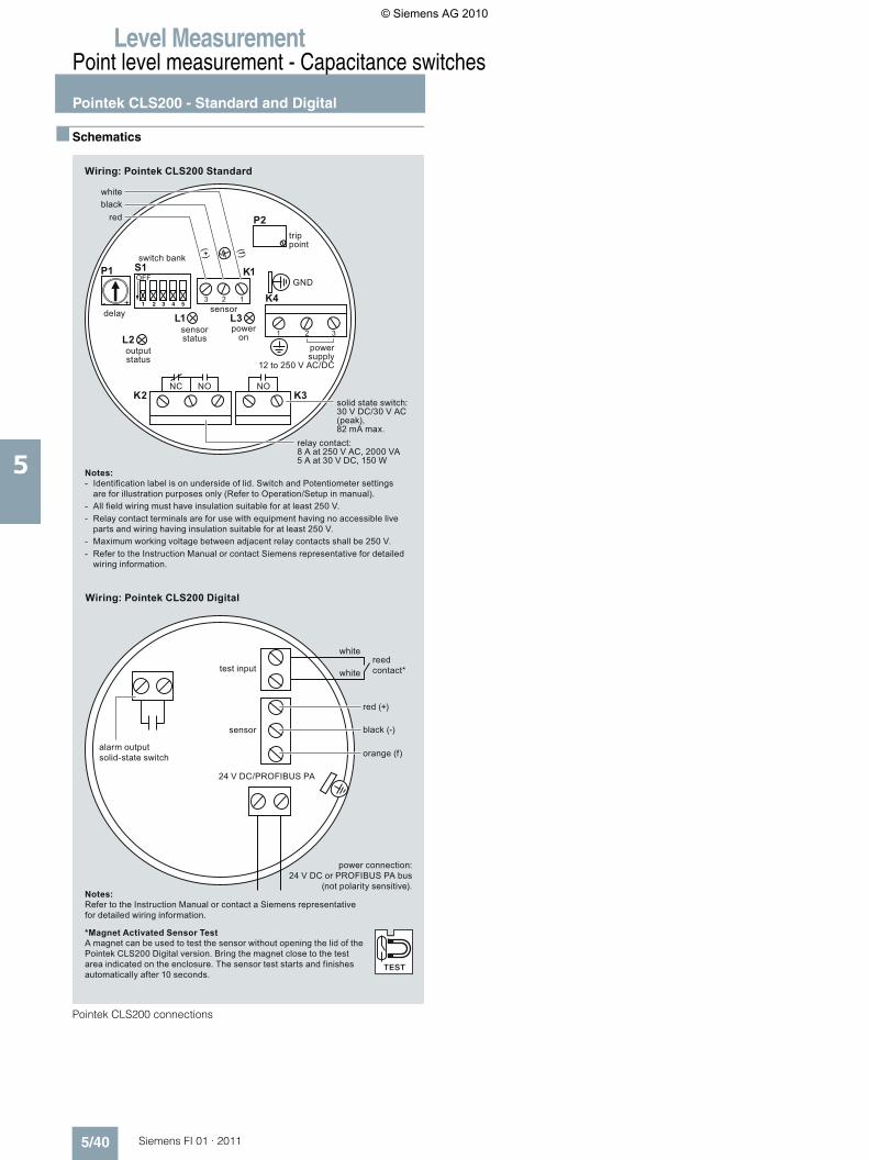
Level MeasurementPoint level measurement - Capacitance switches
Pointek CLS200 - Standard and Digital
5/40 Siemens FI 01 · 2011
5
■ Schematics
Pointek CLS200 connections
white
white
red (+)
Wiring: Pointek CLS200 Digital
solid state switch:30 V DC/30 V AC (peak), 82 mA max.
relay contact:8 A at 250 V AC, 2000 VA5 A at 30 V DC, 150 W
whiteblack
red
sensor status
output status
power on
delay
trip point
sensor
reedcontact*
power connection:24 V DC or PROFIBUS PA bus
(not polarity sensitive).
black (-)
orange (f)
sensor
test input
alarm output solid-state switch
Wiring: Pointek CLS200 Standard
Notes:Refer to the Instruction Manual or contact a Siemens representative for detailed wiring information.
Notes:Identification label is on underside of lid. Switch and Potentiometer settings are for illustration purposes only (Refer to Operation/Setup in manual).
-
All field wiring must have insulation suitable for at least 250 V.-Relay contact terminals are for use with equipment having no accessible live parts and wiring having insulation suitable for at least 250 V.
-
Maximum working voltage between adjacent relay contacts shall be 250 V.-Refer to the Instruction Manual or contact Siemens representative for detailed wiring information.
-
*Magnet Activated Sensor TestA magnet can be used to test the sensor without opening the lid of the Pointek CLS200 Digital version. Bring the magnet close to the test area indicated on the enclosure. The sensor test starts and finishes automatically after 10 seconds.
power supply
12 to 250 V AC/DC
NC NO NO
switch bank
GND
3 2 1
321
+-
24 V DC/PROFIBUS PA
K2
K4
K1
L3L1
S1P1
L2
K3
P2
OFF
(+)
(f)
© Siemens AG 2010