let's create a graphical modeling editor for a robot · let's create a graphical modeling...
TRANSCRIPT

Let's create a graphical
modeling editor for a robot !
EclipseCon France 2016


He can perform basic actions
Going Forward
Going Backward
Rotate
Going To a Position
Delay
Grab an object
Release an object
Returning to origin position

… and collect data
Object touched ?
Recognized color
Distance to obstacle

Java program
• Our robot is controlled by a program written in Java
• Based on a small framework on top of LeJOS EV3

Workshop objective
Create a graphical editor to define the choregraphy of the robot
Choregraphy editor Code Generator Java Program

The easiest way to get your own Modeling Tool
An Eclipse project created by
Thales & Obeo

Sirius Principles
Specification Environment Runtime Environment
Tool Specifiers/Developers End Users

Resources
Data Domain
Representations Modeling Tool created with
conforms to
references represent
Tool Specifiers/Developers End Users

Workshop steps
• Step 0: Preparation
• Step 1: Basic diagram
• Step 2: Advanced diagram
• Step 3: Compartments and Properties Views

Workshop steps
• Step 0: Preparation
• Step 1: Basic diagram
• Step 2: Advanced Diagram
• Step 3: Compartments and Properties Views
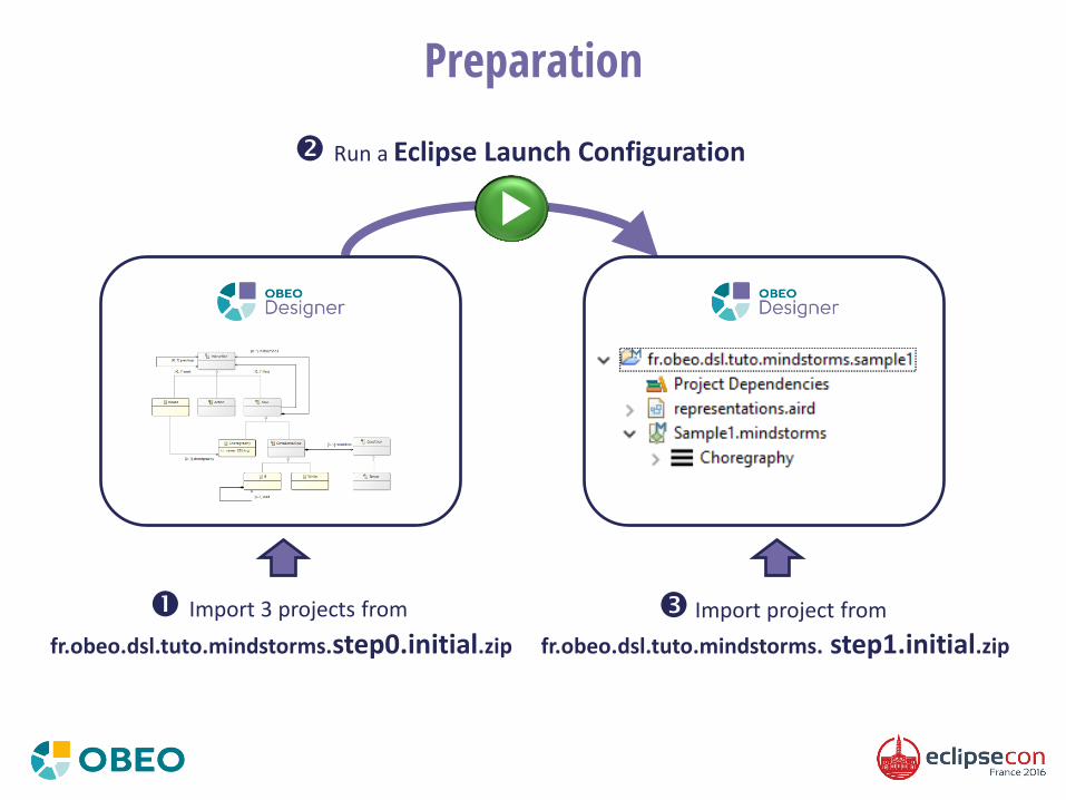
Preparation
Import 3 projects from
fr.obeo.dsl.tuto.mindstorms.step0.initial.zip
Import project from
fr.obeo.dsl.tuto.mindstorms. step1.initial.zip
Run a Eclipse Launch Configuration

Domain Model

Domain Model

Workshop steps
• Step 0: Preparation
• Step 1: Basic diagram
• Step 2: Advanced Diagram
• Step 3: Compartments and Properties Views

Step 1: Objectives
• Create a basic Diagram to display a simple flow:
– Diagram elements
• Start of the flow (the flow itself)
• ReturnToBase actions
• Rotate to left actions (the rotate instances with degrees > 0)
• Link from the start and the first node of the flow (the reference ‘first’ of the flow)
• Link between an action and its next action (the reference ‘next’ of each action)
– Node creation tools
• Create a ReturnToBase tool
• Create a Rotate to left tool

Step 1: Sirius Concepts (1/2)
• Viewpoint Specification Project
– The Eclipse project that defines a Sirius modeling tool
– Contains a odesign files that describes the representations and Java services used by the tool
• Viewpoint
– A viewpoint defines Sirius representations (diagrams, tables, matrices, trees) dedicated to a specific need
• Diagram Description
– Describes a kind of graphical representation for your model
– It defines which elements to display on the diagramm, how (style) and the tools to edit them
• Node
– Describes model elements displayed via an image or a simple shape
– It defines how to find the model elements to display
– It defines a graphical style (shape, label, color, …)
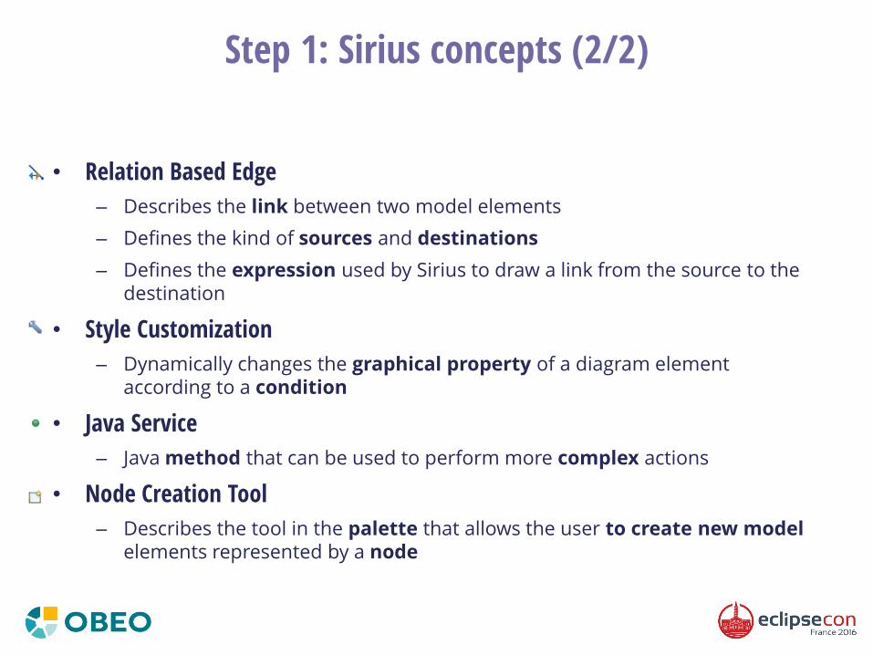
Step 1: Sirius concepts (2/2)
• Relation Based Edge
– Describes the link between two model elements
– Defines the kind of sources and destinations
– Defines the expression used by Sirius to draw a link from the source to the destination
• Style Customization
– Dynamically changes the graphical property of a diagram element according to a condition
• Java Service
– Java method that can be used to perform more complex actions
• Node Creation Tool
– Describes the tool in the palette that allows the user to create new model elements represented by a node
Workshop steps
• Step 0: Preparation
• Step 1: Basic diagram
• Step 2: Advanced diagram
• Step 3: Compartments and Properties Views
• Step 4: Java Generator
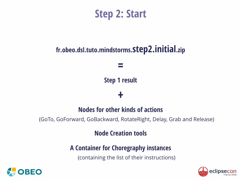
Step 2: Start
fr.obeo.dsl.tuto.mindstorms.step2.initial.zip
= Step 1 result
+ Nodes for other kinds of actions
(GoTo, GoForward, GoBackward, RotateRight, Delay, Grab and Release)
Node Creation tools
A Container for Choregraphy instances
(containing the list of their instructions)

Step 2: Objectives
• Declare a custom color
– Used on Choregraphy containers
• Display Reuse instances
– With the instructions of the reused Choregraphy
• Create other edition tools
– A dialog-box to select a Choregraphy when creating a Reuse
– A tool in the palette to create links
– Double-click on a Choregraphy to create/open a new diagram
– The possibility to edit labels on graphical elements
– The possibility to change the destination of a link

Step 2: Concepts (1/2)
• User Colors Palette
– Defines specific colors that you can use for the diagram elements (background, foreground, border, …)
• Container
– Describes graphical model elements that can contain other elements (as free form, lists or compartments)
– Defines how to find the container elements to display and their sub-elements (nodes, containers, ports)
– Defines a graphical style (shape, label, color, …)
• Select Model Element Variable
– Can be used by tools to interactively propose a list of model elements to select by the user

Step 2: Concepts (2/2)
• Edge Creation tool
– Describes the tool in the palette that allows the user to create a link between two graphical elements
• Double-Click tool
– Defines which actions to execute when the user double-click on a graphical element
• Direct Edit Label tool
– Defines how to interpret the label value changes that are made directly on the diagram
• Reconnect Edge tool
– Defines how to interpret the modification of edges ends (origin or destination) made directly from the diagram
Element
Source
Target
Before
Element
Source
Target
After
Workshop steps
• Step 0: Preparation
• Step 1: Basic diagram
• Step 2: Advanced Diagram
• Step 3: Compartments and Properties Views

Step 3: Start
fr.obeo.dsl.tuto.mindstorms.step3.initial.zip
= Step 2 result
+ Containers for While and If
A validation rule
Other edition Tools
(diagram creation, delete for nodes and edges)

Step 3: Objectives
• Complete the If container
– Display its instructions in a first compartment
– Display elsifs instructions in distinct containers
• Provide specific properties views
– Previous and Next
• On the same row
• Filled only with instructions of the current flow, without current instruction
– Degrees (for Rotate instances)
• Disabled if random is checked
• Yellow background if value is not between -180 and 180
• Warning if value is null and random is not checked

Step 3: Concepts
• Stack option for Container’s children presentation
– Defines when the sub-containers are displayed as Vertical or Horizontal stacks
• Properties Views Description
– Describes how model element properties are edited in the Eclipse Properties Views

Thank you!
Other tutorials on Sirius website
http://www.eclipse.org/sirius/getstarted.html
Research project Funded by

Focus on EclipseCon Agenda
– Automatic Layout for Complex Diagrams Is Coming to Eclipse
• Jaafar Bouayad | Wednesday 8/6 - 10:00 to 10:35
– Modeling Avengers : Open Source Technology Mix for Saving the World
• Cédric Brun | Wednesday 8/6 - 11:00 to 11:35
– Viewpoint: the making of Customizing Capella with Capella Studio in 20 minutes
• Benoit Langlois & Matthieu Helleboid| Wednesday 8/6 - 11:45 to 12:20
– Your Journey From First Experimentation to Large Deployment
• Etienne Juliot | Wednesday 8/6 - 15:00 to 15:35
– eWORMS, the eclipse WORkflow Modeling System for Flight Physicists at AIRBUS
• Alexandra Bœuf | Wednesday 8/6 - 16:00 to 16:35
– Sirius 4.0 : Let Me Sirius That For You!
• Mélanie Bats & Stéphane Bégaudeau | Wednesday 8/6 - 16:45 to 17:20

15/11/2016 Paris XV - Novotel Vaugirard
Talks Clinic Tutorials
Call For Papers Now Open!