lehx0534-xq rental (page 1) · pdf filerental xq2000 sound attenuated power module 60 hz...
TRANSCRIPT
R E N T A L
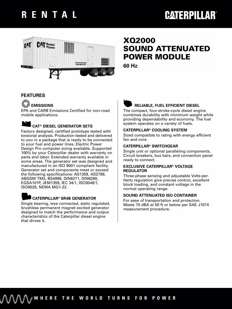
XQ2000SOUND ATTENUATEDPOWER MODULE60 Hz
FEATURES
EMISSIONS
EPA and CARB Emissions Certified for non-roadmobile applications.
CAT® DIESEL GENERATOR SETS
Factory designed, certified prototype tested withtorsional analysis. Production tested and deliveredto you in a package that is ready to be connectedto your fuel and power lines. Electric PowerDesign Pro computer sizing available. Supported100% by your Caterpillar dealer with warranty onparts and labor. Extended warranty available insome areas. The generator set was designed andmanufactured in an ISO 9001 compliant facility.Generator set and components meet or exceedthe following specifications: AS1359, AS2789,ABGSM TM3, BS4999, DIN6271, DIN6280,EGSA101P, JEM1359, IEC 34/1, ISO3046/1,ISO8528, NEMA MG1-22.
CATERPILLAR® SR4B GENERATOR
Single bearing, wye connected, static regulated,brushless permanent magnet excited generatordesigned to match the performance and outputcharacteristics of the Caterpillar diesel enginethat drives it.
RELIABLE, FUEL EFFICIENT DIESEL
The compact, four-stroke-cycle diesel enginecombines durability with minimum weight whileproviding dependability and economy. The fuelsystem operates on a variety of fuels.
CATERPILLAR® COOLING SYSTEM
Sized compatible to rating with energy efficientfan and core.
CATERPILLAR® SWITCHGEAR
Single unit or optional paralleling components.Circuit breakers, bus bars, and connection panelready to connect.
EXCLUSIVE CATERPILLAR® VOLTAGEREGULATOR
Three-phase sensing and adjustable Volts-per-Hertz regulation give precise control, excellentblock loading, and constant voltage in thenormal operating range.
SOUND ATTENUATED ISO CONTAINER
For ease of transportation and protection.Meets 70 dBA at 50 ft or below per SAE J1074measurement procedure.
W H E R E T H E W O R L D T U R N S F O R P O W E R
CAT SR4B GENERATOR
Type . . . . . . Static regulated brushless PM excitedConstruction . . . . . . Single bearing, close coupledThree-phase . . . . . . . . . . . Wye connected — 6 leadInsulation . . . . . . . . . . . Class H — 2 extra dips and
bakes on random wound unitsEnclosure . . . . . . . . . . . . . . . . . . . . . . . . . . . Drip proofAlignment . . . . . . . . . . . . . . . . . . . . . . . . . . . Pilot shaftOverspeed capability . . . . . . . . . . . . . . . . . . . . . 130%Voltage regulator . . . . . . . . . . 3-phase sensing with
Volts-per-HertzVoltage regulation . . . . . . . . . . . . . . Less than ± 0.5% Voltage gain . . . . . . Adjustable to compensate for
engine speed droop and line lossWave form . . . . . . . . . . . . . . Less than 5% deviationTIF. . . . . . . . . . . . . . . . . . . . . . . . . . . . . . . . Less than 50THD. . . . . . . . . . . . . . . . . . . . . . . . . . . . . . Less than 3%
CAT® 3516B ENGINE
V-16, 4-stroke-cycle dieselBore — mm (in) . . . . . . . . . . . . . . . . . . . . . . . 170 (6.7)Stroke — mm (in) . . . . . . . . . . . . . . . . . . . . . 190 (7.5)Displacement — L (cu in) . . . . . . . . . . . . 69.0 (4210)Aspiration. . . . . . . . . . . . Turbocharged-Aftercooled
SPECIFICATIONS
R E N T A L
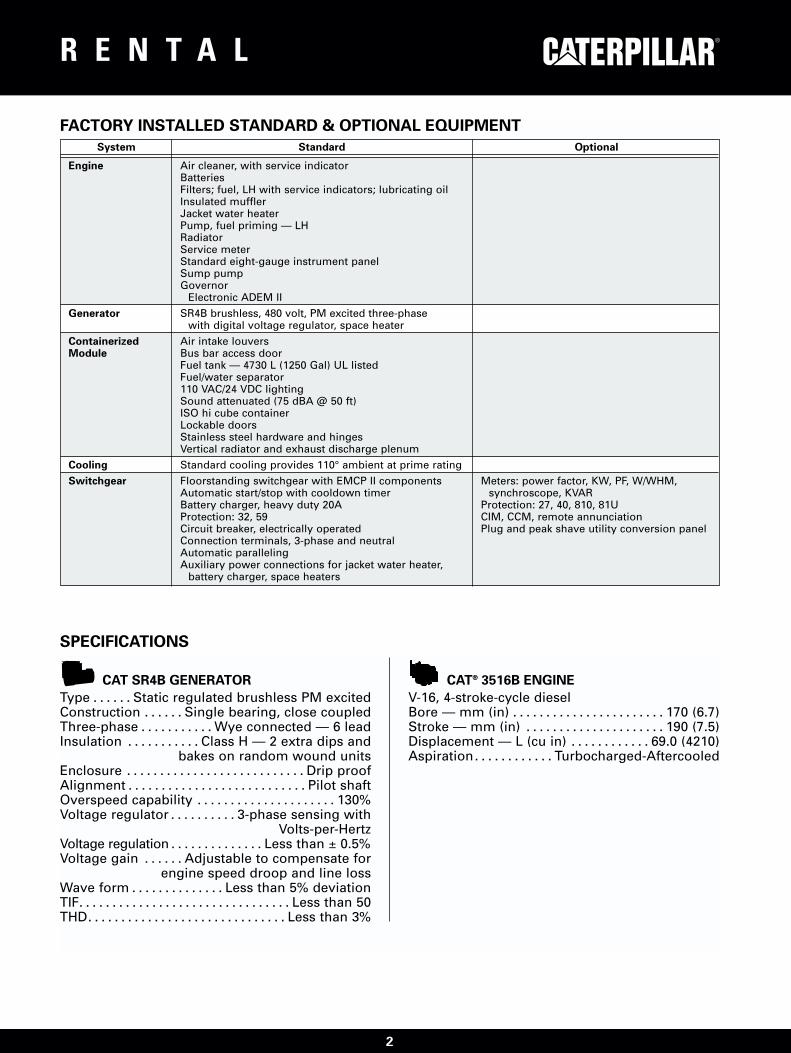
FACTORY INSTALLED STANDARD & OPTIONAL EQUIPMENT
System Standard Optional
Engine Air cleaner, with service indicatorBatteriesFilters; fuel, LH with service indicators; lubricating oilInsulated mufflerJacket water heaterPump, fuel priming — LHRadiatorService meterStandard eight-gauge instrument panelSump pumpGovernor
Electronic ADEM II
Generator SR4B brushless, 480 volt, PM excited three-phasewith digital voltage regulator, space heater
Containerized Air intake louversModule Bus bar access door
Fuel tank — 4730 L (1250 Gal) UL listedFuel/water separator110 VAC/24 VDC lightingSound attenuated (75 dBA @ 50 ft)ISO hi cube containerLockable doorsStainless steel hardware and hingesVertical radiator and exhaust discharge plenum
Cooling Standard cooling provides 110° ambient at prime rating
Switchgear Floorstanding switchgear with EMCP II components Meters: power factor, KW, PF, W/WHM,Automatic start/stop with cooldown timer synchroscope, KVARBattery charger, heavy duty 20A Protection: 27, 40, 810, 81UProtection: 32, 59 CIM, CCM, remote annunciationCircuit breaker, electrically operated Plug and peak shave utility conversion panelConnection terminals, 3-phase and neutralAutomatic parallelingAuxiliary power connections for jacket water heater,
battery charger, space heaters
2

R E N T A L
Container Dimensions
The power module must have support under the center when seton the ground.
Power Rating Standby Prime60 Hz ekW 2000 1825
Engine and Container InformationEngine Model 3516BContainer size m (ft) 12 (40)Container dimensions see below
Fuel Capacity Hours of Operation at 60% Load Factor
4732 L (1250 Gal) Standard 12 m (40 ft) hours 8 9
Approximate Weight (Dry) — Container with Generator Set and Switchgear
Including Container kg (lb) 32 660 (72,000)With Undercarriage kg (lb) 40 370 (89,000)
TECHNICAL DATA
Dimensions
Length 13500.1 mm 531.50 in
Width 2438.4 mm 96.00 in
Height 4114.8 mm 162.00 in
3

R E N T A L
12 m (40 ft) CONTAINERS480V/60 HzFloorstanding switchgear includes thefollowing functions and features:
ELECTRONIC MODULAR CONTROL PANEL(EMCP II) COMPONENTS
GENERATOR SET CONTROL (GSC)
MonitoringSequentially rotating, backlit LCD displayof engine hours, engine rpm, DC batteryvoltage, oil pressure, and watertemperature. Includes pushbutton to holddisplay on any single parameter.
ProtectionShutdowns:
Overspeed, overcrank, high watertemperature, low oil pressure, andemergency stop. With LED indicator foreach condition.
Alarms:Low coolant level
AC MeteringThree-phase volts (L-L), amperes andfrequency with phase select pushbutton,on backlit LCD. Metering accuracy is0.5%.
ControlAutomatic starting with field adjustablecycle crank, failure to start (overcrank),and cooldown timer.
Programming and DiagnosticsIncludes field programmable set-points forengine control and monitoring variablesand self diagnosis of EMCP II systemcomponent and wiring failures.
ALARM MODULE
Flashing LED warnings for: low coolanttemperature, high coolant temperature(pre-alarm), low oil pressure (pre-alarm),engine control switch not in automatic, andlow DC voltage. Includes alarm horn andacknowledge pushbutton.
ENGINE CONTROL SWITCH
Snap action rotary switch, four-position —off/reset, automatic, manual,stop/cooldown. Off/reset for engineshutdown and resetting faults, automaticfor remote starting by customer contactclosure, manual for local starting andmanual paralleling, stop/cooldown formanual operation cooldown.
ALARM ACKNOWLEDGE/LAMP TESTSWITCH
Three-position, spring return to centerswitch for alarm acknowledge and lamptest of all discrete indicating lamps. Lamptest shall also sound the alarm horn.
ANNUNCIATION CIRCUITS
Upon receipt of an alarm or shutdowncondition, the horn shall sound and an LEDshall flash. Upon acknowledgement fromalarm acknowledge/lamp test switch, thehorn shall be silenced and the lampsteadied. LED shall be extinguished whenECS is placed in the off/reset position if thealarm condition has been corrected.Circuits are recurring such that the LEDshall flash and the horn sound, shouldanother fault occur even prior to correctionof the initial fault.
EMERGENCY STOP PUSHBUTTON
Mushroom head, twist to reset, causesengine shutdown and tripping of thegenerator circuit breaker. Prevents enginestarting when depressed.
MANUAL PARALLELING
Controls consisting of reverse power relay,synchronizing lights, and switch. Reversepower condition causes tripping of thegenerator circuit breaker, immediate engineshutdown, flashing of indicating lamp, andsounding of alarm horn.
CIRCUIT BREAKER
Fixed mounted, three-pole, manuallyoperated, molded case circuit breaker withsolid state trip unit for overload (timeovercurrent) and fault (instantaneous)protection. Includes DC shunt trip coilactivated on any generator set monitoredfault. Circuit breaker is sized for full loadcapacity of the generator set at 0.8 powerfactor.
LOAD SHARE GOVERNOR
Electronic load sharing governor withspeed adjust potentiometer, idle/ratedswitch, and isochronous/droop switch.
VOLTAGE REGULATOR
Standard Caterpillar generator-mounteddigital voltage regulator with voltage adjustrheostat mounted in the floorstandingswitchgear.
STANDARD CONTROLS
4

R E N T A L
STANDARD CONTROLS (Continued)
CURRENT TRANSFORMERS (3)
Five-ampere secondary with shortingterminal strips
POTENTIAL TRANSFORMERS (3)
120 VAC secondary with primary andsecondary fuse protection, two connectedto the generator side of the circuit breaker,one connected to the load side of thecircuit breaker.
BUS BARS
Three-phase plus fully rated neutral busbars with NEMA standard hole pattern forconnection of customer load cables andgenerator cables. Bus bars are sized forfull load capacity of the generator set at0.8 power factor. Also includes ground bus,connected to the generator frame groundand container frame with holes forconnection of field ground cable. Bus barsare accessible from outside of the powermodule via hinged, lockable cable accessdoor.
ACCESSORY POWER
3500 Power ModulesThree 230 VAC (50 Hz units) or 120 VAC (60 Hz units) shore power connections forjacket water heaters, generator spaceheater, and battery charger.
BATTERY CHARGER
24 VDC/20A battery charger with float/equalize modes and charging ammeter.
5

R E N T A L
www.CAT-ElectricPower.com
© 2000 CaterpillarAll rights reserved.
U.S. sourced Printed in U.S.A.
LEHX0534 (10-00) Materials and specifications are subject to change without notice.The International System of Units (SI) is used in this publication.

Maintenance SectionFuel Specifications
Fuel Specifications iOl 096371
Fuel Information for DieselEnginesi01060086
General Fuel Information SMCS Code: 1250; 1280
SMCS Code: 1250; 1280 The two basic types of diesel fuel are No. 2 dieselfuel and No. 1 diesel fuel. No. 2 diesel fuel is aheavier diesel fuel than No. I diesel fuel. Heavierfuels can cause problems with fuel filters, fuellines, fuel tanks, and fuel storage in cold weather.Heavier diesel fuels such as No. 2 diesel fuel canbe used in diesel engines that operate in coldtemperatures with a minimum amount of pour pointdepressant additive. For more information on fuelswhich include blends of No. 1 and No. 2 diesel fuel,consult your fuel supplier.
• Purchase fuel from a reputable supplier,
• Use fuel that meets the minimum Caterpillarspecifications for diesel fuel. The specificationsare included in the table Caterpillar Specificationsfor Distillate Fuel. This table is included in therecommendations for diesel fuel. These fuelshave a minimum lubricity level of 3100 g. Thisresult is obtained by conducting the ScuffingLoad Wear Test (SBOCLE). If a High FrequencyReciprocating Rig (HFRR) is used for testing,the maximum allowable wear scar is .45 mm(0.018 inch) at 60 'C (140 'F). The maximumallowable wear scar is .38 mm (0.01 50 inch) at25 -C (77 -F),
When you use No. 2 diesel fuel or other heavierfuels, some of the fuel's qualities may interferewith successful cold weather operation. Additionalinformation about the characteristics of diesel fuelis available. This information contains a discussionon the modification to the characteristics of dieselfuel. There are several possible methods that canbe used to compensate for the fuel qualities thatmay interfere with cold weather operation. Thesemethods include the use of starting aids, enginecoolant heaters, fuel heaters, and de-icers.
• Keep the fuel storage tank clean of water, debrisand sediment.
• Drain water and sediment from the fuel storagetank weekly. Drain water and sediment before thetank is refilled,
Starting Aids• Keep the area around the fuel tank filler neckclean of debris in order to prevent contaminationof the fuel tank. The use of a starting aid is a conventional method
of assistance for cold starts in low temperatureconditions. A variety of starting aids are availablefor Caterpillar engines. Follow the recommendationsthat are provided by the manufacturer of the startingaid.
• As required, clean the inside of the engine's fueltank.
• Drain water and sediment from the engine's fueltank daily. Drain the tank at the start of a shift.After the fuel tank has been filled, allow the fuelto settle for ten minutes. This will allow the waterand sediment to separate from the fuel. Then,drain the water and sediment from the tank.
Engine Coolant Heaters
These heaters heat the engine coolant. The heatedcoolant flows through the cylinder block. The flowof heated coolant keeps the engine warm. A warmengine is easier to start in cold weather. Mostcoolant heaters use electrical power. A source ofelectricity is necessary for this type of heater. Otherheaters that burn fuel are available as a source ofheat. These heaters may be used in place of theelectrical heaters.
• Install water separators.
• Drain the water from the water separator daily.
• For some applications, Caterpillar high efficiencyfuel filters are required in order to providemaximum life to the fuel system.
With either type of heater, starting aids and/or fuelswith higher cetane numbers are less importantbecause the engine is warm. Problems with fuelcloud point can cause the plugging of fuel filters.Problems with fuel cloud point cannot be correctedby engine coolant heaters. This is especially truefor fuel filters that are cooled by air flow duringoperation.
• Change fuel filters at the scheduled interval.Never fill the new fuel filter with fuel beforeinstallation. Use the fuel priming pump to removeair from the system.
• Install breather filters on the fuel tanks.

Maintenance SectionFuel Specifications
Fuel Heaters iOl 1 11474
Fuel RecommendationsThe fuel cloud point is related to problems withfuel filters. The heater heats the fuel above thecloud point before the fuel enters the fuel filter. Thisprevents wax from blocking the filter. Fuel can flowthrough pumps and lines at temperatures below thecloud point. The cloud point is often above the pourpoint of a fuel. While the fuel can flow through theselines, the wax in the fuel can still plug the fuel filter.
SMCS Code: 1250; 1280
Diesel engines have the ability to burn a widevariety of fuels. These fuels are divided into twogeneral groups, The two groups are called thepreferred fuels and the permissible fuels.
The preferred fuels provide maximum engineservice life and performance. The preferred fuelsare distillate fuels. These fuels are commonly calleddiesel fuel, furnace fuel, gas oil, or kerosene.
In some engine installations, small modificationscan prevent problems that are caused by the cloudpoint. One of the following changes can preventproblems in many conditions: a change in thelocation of fuel filters and/or supply lines and theaddition of insulation. In extreme temperatures,heating of the fuel may be required to prevent thefilters from plugging. There are several types of fuelheaters that are available. The heaters use eitherengine coolant or exhaust gas as a heat source.These systems may prevent filter waxing problemswithout the use of cle-icers. These systems may beineffective when the fuel contains a large amountof dirt or of water. Use of a fuel heater can helpeliminate some cold weather problems. A fuelheater should be installed so that the fuel is heatedbefore flowing into the fuel filter.
The permissible fuels are crude oils or blendedfuels. Use of these fuels can result in highermaintenance costs and in reduced engine servicelife.
Diesel fuels that meet the specifications in Table 7will help to provide maximum engine service lifeand performance. In North America, diesel fuel thatis identified as NO. 1-D or No. 2-D in ''ASTM D975''generally meet the specifications. Table 7 is fordiesel fuels that are distilled from crude oil. Dieselfuels from other sources could exhibit detrimentalproperties that are not defined or controlled by thisspecification.Note: Only use fuel heaters that are controlled
by thermostats or use fuel heaters that areself-regulated. Do not use fuel heaters in warmtemperatures.
Table 7
Caterpillar Specifications for Distillate Diesel FuelRequirements ASTM
TestAromatics 35% maximum ''D1319''
Ash 0.02% maximum (weight) ''D482''
Carbon Residueon 1 0% Bottoms
0.35% maximum (weight) ''D524''
Select a fuel heater that is mechanically simple, yetadequate for the application. The fuel heater shouldalso prevent overheating of the fuel. Disconnect thefuel heater or deactivate the fuel heater in warmweather. An unacceptable loss of fuel viscosityand engine power will occur if the fuel supplytemperature is allowed to become too hot.
40 minimum (DI engines)35 minimum (PC engines)
''D613''For additional information on fuel heaters, see yourCaterpillar dealer
Cetane Number
Cloud PointThe cloud point mustnot exceed the lowestexpected ambienttemperature.
-
Copper StripCorrosion
No. 3 maximum ''D130''
De-Icers
De-icers lower the freezing point of the moisture inthe fuel. De-icers are not generally needed whenfuel heaters are used. If you experience trouble,consult your fuel supplier for recommendations of acompatible commercial de-icer 1 0% at 282 OC (540 OF)
maximum
90% at 360 OC (680 OF)maximum
''D86''
Distillation
''D93''legal limitFlash Point(continued)
Specifications

Maintenance SectionFuel Specifications
(Table 7, contd)
NOTICECaterpillar Specifications for Distillate Diesel FuelOperating with fuels that do not meet Caterpillar'srecommendations can cause the following effects:starting difficulty, poor combustion, deposits in thefuel injectors, reduced service life of the fuel system,deposits in the combustion chamber, and reduced
ASTIVIRequirementsSpecificationsTest
30 minimum
45 maximum
''D287"API Gravity
service life of the engine.
Pour Point6 OC (10 ''F) minimumbelow ambienttemperature
''D97''
Sulfur (1)3% maximum ''D3605''
or''D1 552''
KinematicViSCOSity (2)
1.4 cSt minimum and 20.0cSt maximum at 40 OC(104 -F)
''D445''
Water andSediment
0.1% maximum ''131796''
Water 0.1% maximum ''D1744''
Sediment 0.05% maximum (weight) ''D473''
Gums andResins (3)
10 mg per 100 mLmaximum
''D381 ''
In the USA, 0.05 percent diesel fuels have beenused in all on-highway truck engines since IJanuary 1994. This low sulfur diesel fuel wasmandated as a means of directly reducingparticulate emissions from diesel truck engines.This low sulfur fuel will also be used in Caterpillarcommercial diesel engines when low emissions arerequired or when the fuel supply sources providethis type of fuel. Caterpillar has not seen anydetrimental effects with 0.05 percent sulfur fuel inCaterpillar diesel engines.
NOTICEHeavy Fuel Oil (HFO), Residual fuel, or Blended fuelmust NOT be used in Caterpillar diesel engines (ex-cept in 3600 Series HFO engines). Severe compo-nent wear and component failures will result if HFOtype fuels are used in engines that are configured to
''D6708''3100 g minimum
0.45 mm (0.018 inch)maximum at 60 OC(140 OF)
0.38 mm (0.01 5 inch)maximum at 25 'C (77 'F)
use distillate fuel.Lubricity (4)
''D6079''In extreme cold ambient conditions, you mayuse the distillate fuels that are specified in Table8. However, the fuel that is selected must meetthe requirements that are specified in Table 7.These fuels are intended to be used in operatingtemperatures that are down to -54 OC (-65 OF).
(1) Caterpillar fuel systems and engine components canoperate on high sulfur fuels. Fuel sulfur levels affect exhaustemissions. High sulfur fuels also increase the potential forcorrosion of internal components. Fuel sulfur levels above 1.0percent may significantly shorten the oil change interval. Foradditional information, see this publication, ''Engine Oil'' topic Table 8(Maintenance Section). Distillate Fuels (1)(2) The values of the fuel viscosity are the values as the fuelis delivered to the fuel injection pumps. If a fuel with a lowviscosity is used, cooling of the fuel may be required tomaintain a 1.4 cSt viscosity at the fuel injection pump. Fuelswith a high viscosity might require fuel heaters in order tobring down the viscosity to a 20 cSt viscosity. For additionalinformation, see Special Publication, SEBDO717, ''Diesel Fuel
Specification Grade''MIL-T-5624R'' JP-5
''ASTM D1655'' Jet-A-1
''MIL-T-83133D'' JP-8and Your Engine''(3) Follow the test conditions and procedures for gasoline (motor).
(1) The fuels that are listed in this Table may not meet(4) The lubricity of a fuel is a concern with low sulfur fuel. To the requirements that are specified in the ''Caterpillar
Specifications for Distillate Diesel Fuel'' Table. Consult thesupplier for the recommended additives in order to maintainthe proper fuel lubricity.
determine the lubricity of the fuel, use either the ''ASTIVI D6708Scuffing Load Wear Test (SBOCLE)'' or the ''ASTIVI D6079High Frequency Reciprocating Rig (HFRR)'' test. If the lubricityof a fuel does not meet the minimum requirements, consultyour fuel supplier. Do not treat the fuel without consultingthe fuel supplier. Some additives are not compatible. Theseadditives can cause problems in the fuel system.
These fuels are lighter than the No. 2 grades of fuel.The cetane number of the fuels in Table 8 must beat least 40. If the viscosity is below 1.4 cSt at 38 OC(100 OF), use the fuel only in temperatures below0 OC (32 OF), Do not use any fuels with a viscosityof less than 1.2 cSt at 38 'C (100 OF). Fuel coolingmay be required in order to maintain the minimumviscosity of 1.4 cSt at the fuel injection pump.

Maintenance SectionFuel Specifications
There are many other diesel fuel specifications thatare published by governments and by technologicalsocieties. Usually, those specifications do notreview all the requirements that are addressedin this specification. To ensure optimum engineperformance, a complete fuel analysis should beobtained before engine operation. The fuel analysisshould include all of the properties that are listed inTable 7.
The fluid's lubricity describes the ability of the fluidto reduce the friction between surfaces that areunder load. This ability reduces the damage thatis caused by friction. Fuel injection systems relyon the lubricating properties of the fuel. Until fuelsulfur limits were mandated, the fuel's lubricity wasgenerally believed to be a function of fuel viscosity.
The process that is most commonly used to removesulfur from fuel is called hydro-treatment, Thisprocess is also the most economical process. Eachsource of crude oil contains different amountsof sulfur. Crude oils with low sulfur require littlehydro-treatment to obtain the 0.05 percent limit.Crude oils with high sulfur require a more severetreatment.
iOl 1 11650
Characteristics of Diesel FuelSMCS Code: 1250; 1280
The primary characteristics that affect engineoperation and performance in cold temperaturesare the following characteristics: Lubricity, Viscosity,Cetane Number, Cloud Point, Pour Point, andMoisture Content.
The Hydro-treatment removes the fuel's sulfur aswell as other components. The treatment removesnitrogen compounds, polar materials, bicyclicaromatics, polycyclic aromatics, and oxygencompounds. While the removal of sulfur has shownno detrimental effects to the engine, the removal ofother compounds have lowered the lubricity of thefuel. As a result of the lowered lubricity, the fuel isless tolerant of contamination by water and dirt. Thelower fuel lubricity can be seen as abrasive wearof fuel system components. Fuels that have a lowlubricity may not provide adequate lubrication toplungers, to barrels, and to injectors. This problemmay be compounded in areas that require winterblends of fuel. The lighter winter fuel blend hasthe following characteristics: lower viscosity, lowercloud point, and lower pour point.
Refer to Special Publication, SEBDO717, ''DieselFuels and Your Engine'' for information about thefollowing fuel properties: ignition quality, gravity(density), viscosity, cloud point, pour point, andsulfur content.
Lubricity and Low Sulfur FuelNote: The fuel lubricity is important, You shouldconsider the fuel's lubricity whenever you operatethe equipment in arctic weather. Also, you shouldconsider the fuel's lubricity whenever you usefuels that are lower in viscosity. There are manyaftermarket additives that are available to treat fuel.If the fuel's lubricity is an issue, consult your fuelsupplier for proper recommendations regarding fueladditives.
All low sulfur fuels do not have a low lubricity, Thefuel's lubricity may be enhanced with additives.Many fuel suppliers treat the fuel with theseadditives. Do not use a fuel lubricity additive beforeyou consult the fuel's supplier. Some aftermarketadditives may not be compatible with the additivesthat are already in the fuel. Some additive packagesthat are supplied by the aftermarket manufacturermay not be compatible with the seals that are usedin fuel systems of some diesel engines. Otheradditive packages that are supplied by aftermarketmanufacturers cannot provide proper performancein high temperature conditions, These additives mayleave deposits because of the high temperaturesthat exist in the fuel systems of diesel engines.
In the USA, a 0.05 percent limit on the amount offuel sulfur in diesel fuel was mandated in Januaryof 1994 for on-highway trucks. The removal ofsulfur from diesel fuel helps to reduce particulateemissions from diesel engines. While limits forfuel sulfur have not generally been mandatedfor off-highway use, some local governmentshave regulations that include off-highway use.There is frequently no difference in the fuel that issold for different applications. The same fuel isoften used for both on-highway applications andoff-highway applications. Other areas of the worldare mandating similar limits. Regulations continue tobecome more stringent. Lower sulfur limits can beexpected in the future.
Maximum life of the fuel system can be achievedby performing the following tasks: using a reliablefuel supplier, performing proper maintenance of thefuel system, and installing Caterpillar high efficiencyfuel filters in the fuel system.

Maintenance SectionFuel Specifications
Note: Lighter fuels are frequently used in arctictemperatures. Lighter fuels may include the followingfuels: Jet A-1, JP-8, JP-5, and kerosene. The fuellubricity is not a requirement of the specificationsfor these fuels. Do not assume that a fuel meetsthe minimum Caterpillar specification. Contact thefuel supplier for proper recommendations on fuellubricity additives.
Additives can also be used to improve the cetanenumber of a fuel. Additives are evaluated throughtesting in special engines. However, the fuelcharacteristics of additives are not identical to anatural product. While both fuels may be rated ashaving the same cetane number, starting may bedifferent.
Cloud PointViscosityIt is important to understand that the cloud point ofa fuel is different from the pour point. There is norelationship between cloud point and the pour point.The cloud point is the temperature that allows someof the heavier components in the wax to solidify inthe fuel. This wax is not a contaminant in the fuel.The wax is an important element of No. 2 dieselfuel. The wax has a high fuel energy content andthe wax has a very high cetane value. Removal ofthe heavier wax lowers the cloud point of the fuel.Removal of the wax also increases the cost becauseless fuel can be made from the same amount ofcrude oil. Basically, a No. 1 diesel fuel is formulatedby removing the wax from a No. 2 diesel fuel.
The viscosity of the fuel is significant becausethe fuel serves as a lubricant for fuel systemcomponents. Arctic fuels need to have sufficientviscosity. The fuel must lubricate the fuel system ata temperature of OOC (320F) or below freezing. If thekinematic viscosity of the fuel is lower than 1.4 cStas supplied to the fuel injection pump or to the unitinjectors, excessive scuffing and seizure can occur.
Cetane NumberThe cetane number of the fuel has an effect onthe ability of the engine to start. Also, the cetanenumber has an effect on the interval of time beforethe engine runs smoothly. Generally, an increaseof ten in the cetane number will allow the engineto be started at a lower temperature. The startingtemperature can be improved approximately7 to 80C (I 2 to 150F) for every increase of ten in thecetane number. After the engine reaches the normaloperating temperature, a change in the cetanefrom 40 to 50 will have a minimal effect on engineperformance.
The cloud point of the fuel is important becausethe cloud point can limit the performance of thefuel filter. The wax can alter the fuel characteristicsin cold weather, Solid wax can fill the fuel filters.The solidified wax will stop the flow of fuel. Fuelfilters are necessary in order to remove dirt fromthe fuel. The filters block foreign material, and thefilters protect the parts for the fuel injection system.Since fuel must flow through the filters, installinga fuel heater is the most practical way to preventthe problem. A fuel heater will keep the fuel abovethe cloud point as the fuel flows through the fuelsystem. The fuel heater will permit the wax to flowthrough the filters with the fuel.
Most fuels that have a cetane number above 40 willpermit acceptable engine starts in warmer outsidetemperatures. The engine will start satisfactorily withthis fuel when the engine is kept warm. The enginecan be kept warm by using either a heated room ora coolant heater. Modifying the Cloud Point
You can lower the cloud point of a diesel fuel bymixing the diesel fuel with a different fuel that has alower cloud point. No. 1 diesel fuel or kerosene maybe used to lower the cloud point of a diesel fuel.The efficiency of this method is not good, becausethe ratio of the mixture does not have a directrelation to the improvement in cloud point. Theamount of fuel with low cloud point that is requiredmakes the process less preferable to use.
During average starting conditions, direct injectionengines require a minimum cetane number of 40. Ahigher cetane value may be required for operationin high altitudes or for cold weather operation. Theminimum fuel cetane number that is required for theprecombustion engine is 35.
Modifying the Cetane Number
The cetane number of a fuel can be changed ifthe fuel is mixed with a fuel that has a differentcetane number. Generally, the cetane number ofthe mixture will be in direct relation to the ratio ofthe fuels that were mixed. Your fuel supplier canprovide the information about the cetane number ofa particular fuel.

Maintenance SectionFuel Specifications
The following illustration contains a table that can beused to find the necessary mixture for two fuels withdifferent cloud points. In order to use the table, youmust know the exact fuel cloud point of each fuel.This specification can change from one purchase offuel to the next purchase of fuel. This specificationis normally available from personnel at the source ofthe fuel supply. When fuels that have a lower cloudpoint are not available, this method cannot be used.
To measure the pour point, the fuel temperatureis lowered below the cloud point in steps of 30C(50F) at a time, The temperature is lowered untilthe fuel does not flow. The pour point is the lasttemperature that is shown before the flow stops.At the pour point, the wax has solidified out of thefuel. This makes the fuel more solid than liquid,The pour point of the fuel can be improved. Thisdoes not require the removal of important elements.This process is the same process that is used toimprove the cloud point of a fuel.The manufacturer of the fuel can add cold flow
improvers to the fuel. Cold flow improvers modify thewax crystals in the fuels. The cold flow improversdo not change the fuel's cloud point. However, thecold flow improvers keep the wax crystals smallenough to pass through standard fuel filters. Formixing precautions, see the topic ''Pour Point''
A fuel's pour point should be at least 60C (100F)below the lowest ambient temperature that isrequired for engine start-up and for engineoperation. To operate the engine in extremelycold weather, No. 1 fuel or No. I -D fuel may benecessary because of these fuels' lower pourpoints.
Modifying the Pour Point
You can lower the fuel's pour point by usingadditives. You can also lower the pour point bymixing the fuel with a fuel that has a lower pourpoint. See the topic ''Cloud Point'' for the procedure.This procedure is not the best procedure to use.
The same table that was use for cloud point can beused for an estimate of pour points. This is true onlyif the fuels do not have additives which change thepour point.
gOO592741Illustration 5Cloud point of fuel mixturesGenerally, the most practical method that is used to preventproblems that are caused by fuel cloud point at low temperaturesis the use of fuel heaters. In most applications, fuel heaters canbe used at a lower cost than fuel mixtures.
Pour PointThe fuel's pour point is a temperature below thefuel's cloud point. Fuel stops flowing below the pourpoint. The pour point is the temperature which limitsmovement of the fuel with pumps.

Maintenance SectionFuel Specifications
The above example shows that the blending willrequire a thirty percent mixture of lighter fuel.
Additives are a good method to use in order tolower the pour point of a fuel. These additives areknown by the following names: pour depressants,cold flow improvers, and wax modifiers. When theadditives are used in a low concentration, the fuelwill flow through pumps, lines, and hoses. Theseadditives must be thoroughly mixed into the fuel attemperatures that are above the cloud point. Thefuel supplier should be contacted in order to blendthe fuel with the additives. The blended fuel can bedelivered to your fuel tanks.
Moisture ContentProblems with fuel filters can occur at any time. Thecause of the problem can be water in the fuel ormoisture in the fuel. At low temperatures, moisturecauses special problems. There are three types ofmoisture in fuel: dissolved moisture (moisture insolution), free and dispersed moisture in the fuel,and free and settled at the bottom of the tank.
Most diesel fuels have some dissolved moisture.Just as the moisture in air, the fuel can only containa specific maximum amount of moisture at anyone temperature. The amount becomes less asthe temperature is lowered. For example, a fuelcould contain 100 ppm (0.010 percent) of water insolution at 18'C (650F). This same fuel can possiblyhold only 30 ppm (0.003 percent) at 4'C (40'F).
gOO592741Illustration 6Cloud point of fuel mixtures
In order to calculate the amount of lighter fuel thatis required to be blended with the heavier fuel,perform the following steps:
After the fuel has absorbed the maximum possibleamount of water, the additional water will be freeand dispersed. Free and dispersed moisture is finedroplets of water that is suspended in the fuel.Since the water is heavier than the fuel, the waterwill slowly become free and settled at the bottomof the tank. In the above example, when the fueltemperature was lowered from 180C (65'F) to 4'C(40'F), 70 ppm of water became free and dispersedin the fuel.
1. Obtain the specification for fuel cloud point ofboth fuels from your fuel supplier.
2. Locate the cloud point of the heavier fuel on theleft side of the table. Mark the point on the table.
3. Locate the cloud point of the lighter fuel on theright side of the table. Mark the point on thetable.
4. Draw a line between the two points that wereestablished. Label this line ''A''. The small drops of water cause a cloudy
appearance in the fuel. If the change in temperatureis slow, the small drops of water can settle to thebottom of the tank. When the fuel temperatureis lowered rapidly to freezing temperature, themoisture that comes out-of-solution changes to veryfine particles of ice instead of small drops of water.
5. Determine the lowest outside temperaturefor machine operation. Find this point on theleft side of the table. Mark this point. Draw ahorizontal line from this point. Stop the line at theintersection of line ''A''. Label this new line ''C''.
The particles of ice are lighter than the fuel, and theparticles of ice will not settle to the bottom of thetank. When this type of moisture is mixed in the fuel,this moisture will fill the fuel filters. The ice crystalswill plug the fuel filters in the same way as waxplugs the fuel filters.
6. Line ''C'' and line ''A'' intersect. Mark this point.Draw a vertical line from this point. Stop theline at the bottom of the table. Label this line''B''. The point at the bottom of line ''B'' revealsthe percentage of lighter fuel that is required tomodify the pour point.

Maintenance SectionFuel Specifications
If a filter is plugged and fuel flow is stopped,perform the following procedure to determine thecause:
1. Remove the fuel filters.
2. Cut the fuel filters open.
3. Inspect the fuel filter before the filter warms. Thisinspection will show that the filter is filled withparticles of either ice or wax.
The moisture which is free and settled at thebottom of the tank can become mixed with thefuel. The force of any pumping action will mix themoisture with the fuel whenever fuel is transferred.This moisture then becomes free and dispersedwater. This moisture can cause ice in the filters.This moisture can cause other problems with filtersat any temperature. Generally the same force thatmixes the water into the fuel will also mix dirt andrust from the bottom of the tank with the water. Theresult is a dirty mixture of fuel and water which canalso fill the filters and Stop fuel flow.

Maintenance SectionLubricant Specifications
Maintenance Section Table 1
API ClassificationsCurrent Obsolete
CF-4, CG-4, CH-4 CECIF CC, CID
CF-20) CD-20)
Lubricant Specifications01 I 1 1306
Lubricant Information (1) CD-2 and API CF-2 are classifications for two-cycle dieselengines. Caterpillar does not sell engines that utilize CD-2and API CF-2 oils.SMCS Code: 1000; 1300; 7581
Note: API CIF is not the same classification asAPI CF-4. API CF oils are only recommendedfor Caterpillar 3600 Series Diesel Engines andCaterpillar engines with precombustion chamber(PC) fuel systems.
General InformationBecause of government regulations regardingthe certification of engine exhaust emissions, thelubricant recommendations must be followed.
GreaseEngine Manufacturers Association(EMA) Oils The classifications of grease are based on the
''ASTIM D217'' worked penetration characteristics.These characteristics for grease are given a definedconsistency number,
The ''Engine Manufacturers AssociationRecommended Guideline on Diesel Engine Oil'' isrecognized by Caterpillar. For detailed informationabout this guideline, see the latest edition of EMApublication, ''EMA LRG-V.
Terminology
Certain abbreviations follow the nomenclature of"SAF J754'' Some classifications follow "SAF J183''API Oils abbreviations, and some classifications follow the''EMA Recommended Guideline on Diesel EngineOil''. In addition to Caterpillar definitions, thereare other definitions that will be of assistance inpurchasing lubricants. Recommended oil viscositiescan be found in this publication, ''Engine Oil'' topic(Maintenance Section).
The Engine Oil Licensing and Certification Systemby the American Petroleum Institute (API) isrecognized by Caterpillar. For detailed informationabout this system, see the latest edition of the ''APIpublication No. 1509''. Engine oils that bear the APIsymbol are authorized by API.
01072547
Engine OilSMCS Code: 1348
Caterpillar Diesel Engine OilCaterpillar Oils have been developed and tested inorder to provide the full performance and servicelife that has been designed and built into CaterpillarEngines. Caterpillar Oils are currently used to filldiesel engines at the factory, These oils are offeredby Caterpillar dealers for continued use when theengine oil is changed. Consult your Caterpillardealer for more information on these oils.
gOO546535Illustration 1Typical API symbol
Diesel engine oils CC, CD, CD-2, and CE havenot been API authorized classifications since IJanuary 1996, Table 1 summarizes the status of theclassifications.
Due to significant variations in the quality and inthe performance of commercially available oils,Caterpillar makes the following recommendations:
• Caterpillar Diesel Engine Oil (10W30)

Maintenance SectionLubricant Specifications
• Caterpillar Diesel Engine Oil (15W40) EMA LRG-1 The Engine ManufacturersAssociation (EMA) has developed lubricantrecommendations as an alternative to the API oilclassification system. LRG-1 is a RecommendedGuideline that defines a level of oil performancefor these types of diesel engines: high speed,four stroke cycle, heavy-duty, and light duty.LRG-11 oils may be used in Caterpillar engineswhen API CH-4, API CGA and API CF-4 oils arerecommended. LRG-1 oils are intended to providesuperior performance in comparison to API CG-4and API CF-4.
Caterpillar multigrade Diesel Engine Oil isformulated with the correct amounts of detergents,dispersants, and alkalinity in order to providesuperior performance in Caterpillar Diesel Engines.
Caterpillar multigrade Diesel Engine Oil is availablein two viscosity grades (10W30 and 15W40). Fordirect injection engines, see Table 2 in orderto choose the correct viscosity grade for theambient temperature. Multigrade oils provide thecorrect viscosity for a broad range of operatingtemperatures. LRG-1 oils will meet the needs of high performance
Caterpillar diesel engines that are operating inmany applications. The tests and the test limits thatare used to define LRG-1 are similar to the newAPI CH-4 classification, Therefore, these oils willalso meet the requirements of the low emissionsdiesel engines. LRG-1 oils are designed to controlthe harmful effects of soot with improved wearresistance and improved resistance to oil filterplugging. These oils will also provide superior pistondeposit control for engines with either two-piecesteel pistons or aluminum pistons.
Multigrade oils are effective in maintaining low oilconsumption and low levels of piston deposits,
Caterpillar multigrade Diesel Engine Oil can beused in other diesel engines and in gasolineengines. See the engine manufacturer's guide forthe recommended specifications. Compare thespecifications to the specifications of Caterpillarmultigrade Diesel Engine Oil. The current industrystandards for Caterpillar Diesel Engine Oil are listedon the product label and on the data sheets for theproduct. All LRG-1 oils must complete a full test program
with the base stock and with the viscosity grade ofthe finished commercial oil. The use of "API BaseConsult your Caterpillar dealer for part numbers
and for available sizes of containers. Oil Interchange Guidelines'' are not appropriate forLRG-1 oils. This feature reduces the variation inperformance that can occur when base stocks arechanged in commercial oil formulations.Commercial Oils
The performance of commercial diesel engineoils is based on American Petroleum Institute(API) classifications. These API classifications aredeveloped in order to provide commercial lubricantsfor a broad range of diesel engines that operate atvarious conditions.
LRG-1 oils are recommended for use in extendedoil change interval programs that optimize oil life.These oil change interval programs are basedon oil analysis. LRG-1 oils are recommendedfor conditions that demand a premium oil. YourCaterpillar dealer has the specific guidelines foroptimizing oil change intervals.If Caterpillar multigrade Diesel Engine Oil is not
used, only use commercial oils that meet thefollowing classifications: API CH-4 - API CH-4 oils were developed in
order to meet the requirements of the new highperformance diesel engines. Also, the oil wasdesigned to meet the requirements of the lowemissions diesel engines. API CH-4 oils are alsoacceptable for use in older diesel engines and indiesel engines that use high sulfur diesel fuel. APICH-4 oils may be used in Caterpillar engines thatuse API CG-4 and API CF-4 oils. API CH-4 oils willgenerally exceed the performance of API CG-4 oilsin the following criteria: deposits on pistons, controlof oil consumption, wear of piston rings, valve trainwear, viscosity control, and corrosion.
• EMA LRG-1 multigrade oil (preferred oil)
• API CH-4 multigrade oil (preferred oil)
• API CG-4 multigrade oil (preferred oil)
• API CF-4 multigrade oil (acceptable oil)
in order to make the proper choice of a commercialoil, refer to the following explanations:

r
Maintenance SectionLubricant Specifications
Three new engine tests were developed for theAPI CH-4 oil. The first test specifically evaluatesdeposits on pistons for engines with the two-piecesteel piston. This test (piston deposit) also measuresthe control of oil consumption. A second test isconducted with moderate oil soot, The secondtest measures the following criteria: wear of pistonrings, wear of cylinder liners, and resistance tocorrosion. A third new test measures the followingcharacteristics with high levels of soot in the oil:wear of the valve train, resistance of the oil inplugging the oil filter, and control of sludge,
Some commercial oils that meet the APIclassifications may require reduced oil changeintervals. To determine the oil change interval,closely monitor the condition of the oil and performa wear metal analysis. Caterpillar's S 0 S oilanalysis program is the preferred method.
NOTICEFailure to follow these oil recommendations cancause shortened engine service life due to depositsand/or excessive wear.
In addition to the new tests, API CH-4 oils havetougher limits for viscosity control in applicationsthat generate high soot. The oils also have improvedoxidation resistance. API CH-4 oils must pass anadditional test (piston deposit) for engines that usealuminum pistons (single piece). Oil performance isalso established for engines that operate in areaswith high sulfur diesel fuel.
Total Base Number (TBN) and FuelSulfur Levels for Direct Injection(DI) Diesel EnginesThe Total Base Number (TBN) for an oil dependson the fuel sulfur level. For direct injection enginesthat use distillate fuel, the minimum TBN of the newoil must be 10 times the fuel sulfur level, The TBNis defined by "ASTIVI D2896''. The minimum TBN ofthe oil is 5 regardless of fuel sulfur level. Illustration
All of these improvements allow the API CH-4 oil toachieve optimum oil change intervals, API CH-4oils are recommended for use in extended oilchange intervals. API CH-4 oils are recommendedfor conditions that demand a premium oil. YourCaterpillar dealer has specific guidelines foroptimizing oil change intervals.
2 demonstrates the TBN.
17
15
13
API CG-4 - API CG-4 oils were developed primarilyfor diesel engines that use a 0.05 percent level offuel sulfur. However, API CG-4 oils can be usedwith higher sulfur fuels. The TBN of the new oildetermines the maximum fuel sulfur level for APICG-4 and API CF-4 oils. See Illustration 2.
11
7
5
3
API CG-4 oils are the first oils that are required topass industry standard tests for foam control andviscosity shear loss. API CG-4 oils must also passtests that were developed for corrosion, wear andoxidation.
M 1 1.5 20 32.5
gOO104890Illustration 2(Y) TBN by ''ASTM D2896''(X) Percentage of fuel sulfur by weight(1) TBN of new oilAPI CF-4 - These oils service a wide variety of
modern diesel engines. API CF-4 oils provide morestable oil control and reduced piston deposits incomparison to API CF and the obsolete CE and CIDclassifications of oil. API CIF-4 oils provide improvedsoot dispersancy in comparison to API CF andobsolete CID oils. The API CF-4 classification wasdeveloped with a 0.40 percent sulfur diesel fuel.This represents the type of diesel fuels that arecommonly available worldwide.
(2) Change the oil when the TBN deteriorates to 50 percent ofthe original TBN.
Use the following guidelines for fuel sulfur levelsthat exceed 1.5 percent:
• Choose an oil with the highest TBN that meetsone of these classifications: EMA LRG-1, APICHA API CGA and API CF-4.
• Reduce the oil change interval. Base the oilNote: Do not use single grade API CF oils ormultigrade API CF oils in Caterpillar Direct Injection(DI) Commercial Diesel Engines.
change interval on the oil analysis. Ensure thatthe oil analysis includes the condition of the oiland a wear metal analysis.

Maintenance SectionLubricant Specifications
Excessive piston deposits can be produced by anoil with a high TBN. These deposits can lead to aloss of control of the oil consumption and to thepolishing of the cylinder bore.
NOTICEOperating Direct Injected (DI) diesel engines with fuelsulfur levels over 1.0 percent may require shortenedoil change intervals in order to help maintain ade-quate wear protection.
Lubricant Viscosity Recommendationsfor Direct Injection (DI) Diesel Engines
The proper SAE viscosity grade of oil is determinedby the minimum ambient temperature duringcold engine start-up, and the maximum ambienttemperature during engine operation.
Refer to Table 2 (minimum temperature) in order todetermine the required oil viscosity for starting acold engine.
Refer to Table 2 (maximum temperature) in order toselect the oil viscosity for engine operation at thehighest ambient temperature that is anticipated.
Generally, use the highest oil viscosity thatis available to meet the requirement for thetemperature at start-up.
Table 2
Engine Oil Viscosity
Ambient TemperatureCaterpillar DEOMultigrade
EMA LRG-1API CH-4
MaximumMinimumAPI CG-4and API CF-4
Viscosity Grade
SAE OW20 -40 'C (-40 OF) 10 'C (50 OF)
SAE OW30 -40 'C (-40 OF) 30 OC (86 OF)
SAE OW40 -40 'C (-40 OF) 40 'C (104 OF)
SAE 5W30 -30 'C (-22 OF) 30 'C (86 OF)
SAE 5W40 -30 'C (-22 OF) 40 'C (104 OF)
SAE 1OW30 -20 'C (-4 OF) 40 'C (104 OF)
SAE 15W40 -15 'C (5 OF) 50 OC (122 OF)

Maintenance SectionLubricant Specifications
Caterpillar multigrade Diesel Engine Oil isformulated with the correct amounts of detergents,dispersants, and alkalinity in order to providesuperior performance in Caterpillar Diesel Engines.
Caterpillar multigrade Diesel Engine Oil is availablein two viscosity grades (10W30 and 15W40). Forprecombustion chamber engines, see Table 4 inorder to choose the correct viscosity grade for theambient temperature. Multigrade oils provide thecorrect viscosity for a broad range of operatingtemperatures,
Multigrade oils are effective in maintaining low oilconsumption and low levels of piston deposits.
Caterpillar multigrade Diesel Engine Oil can beused in other diesel engines and in gasolineengines. See the engine manufacturer's guide forthe recommended specifications. Compare thespecifications to the specifications of Caterpillarmultigrade Diesel Engine Oil. The current industrystandards for Caterpillar Diesel Engine Oil are listedon the product label and on the data sheets for theproduct.
Consult your Caterpillar dealer for part numbersand for available sizes of containers.
Commercial OilsThe performance of commercial diesel engineoils is based on American Petroleum Institute(API) classifications. These API classifications aredeveloped in order to provide commercial lubricantsfor a broad range of diesel engines that operate atvarious conditions.
i01123508
Engine Oil for PrecombustionChamber (PC) Diesel EnginesSIVICS Code: 1348
If Caterpillar multigrade Diesel Engine Oil is notused, only use commercial oils that meet thefollowing classifications:
Caterpillar Diesel Engine OilCaterpillar Oils have been developed and tested inorder to provide the full performance and servicelife that has been designed and built into CaterpillarEngines. Caterpillar Oils are currently used to filldiesel engines at the factory. These oils are offeredby Caterpillar dealers for continued use when theengine oil is changed. Consult your Caterpillardealer for more information on these oils.
• EMA LRG-1 multigrade oil (preferred oil)
• API CH-4 multigrade oil (preferred oil)
• API CG-4 multigrade oil (preferred oil)
• API CF-4 multigrade oil (acceptable oil)
• API CF oil (acceptable oil for PC engines)
Due to significant variations in the quality and inthe performance of commercially available oils,Caterpillar makes the following recommendations:
In order to make the proper choice of a commercialoil, refer to the following explanations:
• Caterpillar Diesel Engine Oil (10W30)
• Caterpillar Diesel Engine Oil (15W40)

Maintenance SectionLubricant Specifications
EMA LRG-1 - The Engine ManufacturersAssociation (EMA) has developed lubricantrecommendations as an alternative to the API oilclassification system. LRG-1 is a RecommendedGuideline that defines a level of oil performancefor these types of diesel engines: high speed,four stroke cycle, heavy-duty, and light duty.LRG-1 oils may be used in Caterpillar engineswhen API CH-4, API CG-4, and API CF-4 oils arerecommended. LRG-1 oils are intended to providesuperior performance in comparison to API CG-4and API CF-4.
Three new engine tests were developed for theAPI CH-4 oil. The first test specifically evaluatesdeposits on pistons for engines with the two-piecesteel piston. This test (piston deposit) also measuresthe control of oil consumption. A second test isconducted with moderate oil soot. The secondtest measures the following criteria: wear of pistonrings, wear of cylinder liners, and resistance tocorrosion. A third new test measures the followingcharacteristics with high levels of soot in the oil:wear of the valve train, resistance of the oil inplugging the oil filter, and control of sludge.
LRG-1 oils will meet the needs of high performanceCaterpillar diesel engines that are operating inmany applications. The tests and the test limits thatare used to define LRG-1 are similar to the newAPI CH-4 classification, Therefore, these oils willalso meet the requirements of the low emissionsdiesel engines. LRG-1 oils are designed to controlthe harmful effects of soot with improved wearresistance and improved resistance to oil filterplugging. These oils will also provide superior pistondeposit control for engines with either two-piecesteel pistons or aluminum pistons,
In addition to the new tests, API CH-4 oils havetougher limits for viscosity control in applicationsthat generate high soot. The oils also have improvedoxidation resistance. API CH-4 oils must pass anadditional test (piston deposit) for engines that usealuminum pistons (single piece). oil performance isalso established for engines that operate in areaswith high sulfur diesel fuel.
All of these improvements allow the API CH-4 oil toachieve optimum oil change intervals. AN CH-4oils are recommended for use in extended oilchange intervals. API CH-4 oils are recommendedfor conditions that demand a premium oil. YourCaterpillar dealer has specific guidelines foroptimizing oil change intervals.
All LRG-1 oils must complete a full test programwith the base stock and with the viscosity grade ofthe finished commercial oil. The use of "API BaseOil Interchange Guidelines'' are not appropriate forLRG-1 oils. This feature reduces the variation inperformance that can occur when base stocks arechanged in commercial oil formulations.
API CG-4 API CG-4 oils were developed primarily-for diesel engines that use a 0.05 percent level offuel sulfur, However, API CG-4 oils can be usedwith higher sulfur fuels. The TBN of the new oildetermines the maximum fuel sulfur level for APICG-4 and API CF-4 oils, See Illustration 4.
LRG-1 oils are recommended for use in extendedoil change interval programs that optimize oil life,These oil change interval programs are basedon oil analysis. LRG-1 oils are recommendedfor conditions that demand a premium oil. YourCaterpillar dealer has the specific guidelines foroptimizing oil change intervals.
API CG-4 oils are the first oils that are required topass industry standard tests for foam control andviscosity shear loss. API CG-4 oils must also passtests that were developed for corrosion, wear andoxidation.
API CH-4 - API CH-4 oils were developed inorder to meet the requirements of the new highperformance diesel engines. Also, the oil wasdesigned to meet the requirements of the lowemissions diesel engines. API CHA oils are alsoacceptable for use in older diesel engines and indiesel engines that use high sulfur diesel fuel. APICH-4 oils may be used in Caterpillar engines thatuse API CG-4 and API CF-4 oils. API CH-4 oils willgenerally exceed the performance of API CG-4 oilsin the following criteria: deposits on pistons, controlof oil consumption, wear of piston rings, valve trainwear, viscosity control, and corrosion,
API CF-4 - These oils service a wide variety ofmodern diesel engines, API CF-4 oils provide morestable oil control and reduced piston deposits incomparison to API CF and the obsolete CE and CIDclassifications of oil, API CF-4 oils provide improvedsoot dispersancy in comparison to API CF andobsolete CD oils, The API CF-4 classification wasdeveloped with a 0.40 percent sulfur diesel fuel.This represents the type of diesel fuels that arecommonly available worldwide.
Some commercial oils that meet the APIclassifications may require reduced oil changeintervals. To determine the oil change interval,closely monitor the condition of the oil and performa wear metal analysis. Caterpillar's S-0 S oilanalysis program is the preferred method,

Maintenance SectionLubricant Specifications
Lubricant Viscosity Recommendationsfor Precombustion Chamber (PC) DieselEngines
NOTICEFailure to follow these oil recommendations cancause shortened engine service life due to depositsand/or excessive wear. The proper SAE viscosity grade of oil is determined
by the minimum ambient temperature duringcold engine start-up, and the maximum ambienttemperature during engine operation.Total Base Number (TBN) and Fuel
Sulfur Levels for PrecombustionChamber (PC) Diesel Engines Refer to Table 4 (minimum temperature) in order to
determine the required oil viscosity for starting acold engine.The TBN for a new oil depends on the fuel sulfur
level of the fuel that is used, The minimum TBN ofthe oil that is used in PC engines must be 20 timesthe fuel sulfur level. The TBN is defined in ''ASTM
Refer to Table 4 (maximum temperature) in order toselect the oil viscosity for engine operation at thehighest ambient temperature that is anticipated.D2896''. Regardless of fuel sulfur level, the minimum
TBN of new oil is five. Refer to illustration 4. Generally, use the highest oil viscosity thatis available to meet the requirement for thetemperature at start-up.40
.35
Table 430
Engine Oil Viscosity25
Ambient TemperatureCaterpillar DEO23
Multigrade15
EMA LRG-110
API CH-4API CG-45
Minimum MaximumAN CIF-40.5 1 21.5 D 32.5 and API CF
Viscosity Grade
SAE OW20 -40 -C (-40 OF) 10 -C (50 OF)
SAE OW30 -40 -C (-40 OF) 30 -C (86 OF)
SAE OW40 -40 -C (-40 OF) 40 -C (104 OF)
SAE 5W30 -30 OC (-22 OF) 30 OC (86 OF)
SAE 5W40 -30 OC (-22 OF) 40 -C (104 OF)
SAE I OW30 -20 -C (-4 OF) 40 -C (104 OF)
SAE 15W40 -15 -C (5 OF) 50 -C (122 OF)
SAE 30 0 -C (32 OF) 40 -C (104 OF)
SAE 40 5 OC (41 OF) 50 -C (122 OF)
gOO274867Illustration 4(Y) The TBN that is shown by ''ASTM D2896''(X) Percentages of fuel sulfur by weight(1) TBN of new oil(2) Change the oil when the TBN deteriorates to 50 percent of
the original TBN.
Whenever the fuel sulfur exceeds 1.5 percent, dothe following tasks.
• Choose an oil with the highest TBN that meetsone of these classifications: EMA LRG-1, API CF,API CF-4, API CG-4, and API CH-4.
• Shorten the oil change interval if the oil analysisdictates.
Excessive piston deposits can be produced by anoil with a high TBN, These deposits can lead to aloss of control of the oil consumption and to thepolishing of the cylinder bore.
NOTICEOperating PC engines at fuel sulfur levels over 1.0percent may require shortened oil change intervalsto maintain adequate wear protection.
I

CONTENTSDescription PageIntroduction ............................................................................................................... 1Advantages ............................................................................................................... 3Description ................................................................................................................ 6Control Units ............................................................................................................. 7Accessories ............................................................................................................. 23Switch ..................................................................................................................... 36Trip Curves ............................................................................................................. 37Wiring Diagrams ..................................................................................................... 42Circuit Breaker Dimensions .................................................................................... 46Appendix ................................................................................................................. 62
MASTERPACT ® Universal PowerCircuit Breaker
Class 631

1©1995 Square D—All Rights Reserved11/98
Standard Compliance
n UL489: MP08 to MP50 circuit breakers and their accessories are Listed under UL files E63335,E103955 and E113555
n UL1066/ANSI: MC08 to MC50 circuit breakers are UL Listed according to UL1066 (ANSI C37-13)under file E161835
n International Standards: the MASTERPACT® circuit breaker has been designed to meet all themajor standards including:
o IEC 947-2 and related standards such as VDE, BS, EN, etc.o JEC, JISnUL 1008: MP12, MP20 and MP30 circuit breakers are suitable for use in transfer switch
equipmentnMarine Applications:o Homologated by Bureau Veritaso Approved by Det Norske Veritas and Germanische Lloyd'so Listed by Lloyd's Register of Shippingo American Bureau of Shipping applicationo UL marine
High Short-time Current Rating: Up to 100 kA for 1 sec.
The exceptional short-time rating of 75,000 A in a 3000 A frame and 100,000 A in a 4000 A frameand above allows the circuit breakers to be fully selective up to their interrupting ratings.
100% Rated
The circuit breakers are designed for continuous operation at 100% of their current rating.
Other Performances
The UL 489 and UL1066 (ANSI C37-13) standard performance tests assure that the circuit breakerhas sufficient characteristics to be used in normal conditions. However, the circuit breaker exceeds,without additional costs, the UL standard 1,500 operations required in endurance. The heavy-dutymechanism and the contact design provide a mechanical endurance of 10,000 operations (approx.)without maintenance (see page 64).
Tropicalization
The standard moisture and fungus protection ensure normal operation under extreme ambientconditions. MASTERPACT circuit breakers comply with T2 tropicalization (IEC Standard 68-2-30);relative humidity 95% at 113°F (45°C) and 80% at 131°F (55°C) (hot, humid climate). Salt sprayresistance as per IEC 68-2-11.
Poles
The 4-pole version is an efficient solution to ground fault problems created by incorrectly groundedstandby generators and incorrect transfer switching systems. By isolating the neutral of multiplesources coupled together, 4-pole circuit breakers prevent ground faults from returning to the sourcevia unintended paths. Where unintended paths exist, ground fault sensing can become inaccurate orcreate nuisance tripping.
Introduction
Ampere Rating (A) 3-Pole 4-Pole
800 MP-MC MP-MC
1200 MP MP
1600 MP-MC MP-MC
2000 MP-MC MP-MC
2500 MP MP
3000 MP MP
3200 MC
4000 MP-MC MP (1)
5000 MP-MC MP (1)
6300 MP (1)
(1) Not UL Listed.

11/98©1995 Square D—All Rights Reserved2
Introduction
Ratings
Type Ampere Rating (A) Sensor Ratings (A)
MP/MC08 800 250–400–600–800
MP12 1200 800–1200
MP/MC16 1600 1200–1600
MP/MC20 2000 1600–2000
MP25 2500 2000–2500
MP30 3000 2500–3000
MC32 3200 2500–3200
MP/MC40 4000 2500–3000–4000
MP/MC50 5000 4000–5000
MP63 6300 5000–6300
Interrupting Ratings
UL489/NEMA AB1Type Rating (A) 480 Vac 600 Vac Short-time
Standard Interrupting Rating
MP08 H1 800 65 kA 65 kA 50 kA
MP12 H1 1200 65 kA 65 kA 50 kA
MP16 H1 1600 65 kA 65 kA 50 kA
MP20 H1 2000 75 kA 75 kA 75 kA
MP25 H1 2500 75 kA 75 kA 75 kA
MP30 H1 3000 75 kA 75 kA 75 kA
MP40 H1 4000 100 kA 100 kA 100 kA
MP50 H1 5000 100 kA 100 kA 100 kA
MP63 H1 6300 (1) 100 kA 100 kA 100 kA
High Interrupting Rating
MP08 H2 800 100 kA 65 kA 50 kA
MP12 H2 1200 100 kA 65 kA 50 kA
MP16 H2 1600 100 kA 65 kA 50 kA
MP20 H2 2000 100 kA 75 kA 75 kA
MP25 H2 2500 100 kA 75 kA 75 kA
MP30 H2 3000 100 kA 75 kA 75 kA
MP40 H2 4000 125 kA 100 kA 100 kA
MP50 H2 5000 125 kA 100 kA 100 kA
MP63 H2 6300 (1) 150 kA 100 kA 100 kA
(1) Not UL Listed.
UL1066/ANSI C37–13/NEMA SG3Type Rating (A) 508 V 635 V Short-time
Special Interrupting Rating
MC08 N1 800 50 kA 50 kA 42 kA
MC16 N1 1600 50 kA 50 kA 50 kA
Standard Interrupting Rating
MC08 H1 800 65 kA 65 kA 50 kA
MC16 H1 1600 65 kA 65 kA 50 kA
MC20 H1 2000 65 kA 65 kA 65 kA
MC32 H1 3200 65 kA 65 kA 65 kA
MC40 H1 4000 100 kA 100 kA 100 kA
MC50 H1 5000 100 kA 100 kA 100 kA

3©1995 Square D—All Rights Reserved11/98
Advantages
0631
3006
0631
3007
0631
3003
0631
3004
0631
3005
Drawout Circuit Breaker Design
n The drawout assembly mechanism allows the circuit breaker to be racked in four positions(connected, test, disconnected and withdrawn).
n The closing and opening push buttons, the racking handle and racking mechanism are accessiblethrough the front door cutout. Therefore the circuit breaker can be disconnected without openingthe door and accessing live parts. Safety shutters can be provided as an option for protection fromlive parts when the circuit breaker is removed.
Connected Position Test Position Disconnected Position
True Two-step Stored Energy Mechanism
The closing time is less than five cycles. The circuit breaker is operated via a stored-energymechanism which can be manually or motor charged. Closing and opening operations can be initiatedeither from the local push buttons on the circuit breaker front face or by remote control.O–C–O cycle is possible without recharging.
Designed for No Maintenance...
The circuit breaker has fewer parts (by a factor of at least five) than conventional circuit breakerswhile performing the same functions. This leads to greatly enhanced reliability and reduction inmaintenance. Under normal operating conditions, according to standards and controlled by tests, thecircuit breaker does not require maintenance.
…But Exceeds Standards with an Easy and Reduced Maintenance
It is easy to remove the arc chutes and visually inspect the contacts and wear indicator. The operationcounter (spring-charging motor option) can also indicate when inspections and possible maintenanceshould be done. After operating conditions exceeding those given by standards, it is possible toextend the circuit breaker life by:n Replacement of arc chutes and spring charging motor by the user.n Replacement of main contacts by an after sale service team.Note: See pages 62–63 for additional information.
Contact Good(Circuit Breaker Closed)
Contact Worn(Circuit Breaker Closed)

11/98©1995 Square D—All Rights Reserved4
Front Connection of Secondary Circuits
All accessory terminals are located on a connecting block which is accessible from the front evenwith the circuit breaker in the test or disconnected position. This is particularly useful for fieldinspection and modification.
0631
3010
0631
3009
Advantages
Field-installable Accessories
n As the installation develops and changes, the circuit breaker can develop and change with it.Most accessories are field-installable, without losing the UL Listing mark, without any adjustmentand with only the aid of a screwdriver.
n The uniform design of the circuit breaker line allows these accessories to be common for thewhole line.
0631
3008
Opush OFF
M08 H2masterpact
connected
test
disconnected
O OPENdischarged
I
push ON circuit breaker
3 pole600V 50/60Hz
frame size 2000A
suitable for continious operation
at 100% rating in a minimum cubical
space H17.5 by W21 by D14.1/4 inches
ventilation is not required
NEMAinterrupting rating
max RMS sym amps
Volts Amps
240 100K
480 100K
600 65K
IEC 957-2 690V 50/60Hz
interrupting rating
Icu 380/440V 75KA
660V 75KA
Icu 380/440V 75KA
660V 75KA
short time rating
Icw=75KA 0.5 sec.
push to reset
I
I1 I2 I3
90%
50%
20%
STR 58 U
Ir
90
105%Ir
.88.9 .92
.95
.981.8
.85
xIo
Im tm
3
4 56
8
101.52
xIo
.3
.4 .3
.1
.1.2
on I2t off
.2
0
Ir fault
tr
Im fault
tm
I
faultIh
th
t
i
test
+ S –
– T +
T
F
Ihth
400
500 600800
1000
1200250
320
A
.3
.4 .4
.2
.1.2
on I2t off
.3
.1
I
off2
xIn
Ir :
Im :
th :
I
IG LI
G
LLG
LIG
off
reset V
tr
60
120 240
480
1530
at 1,5Ir
4
6
8 12
17
22
Ic1Ic2
.86
.9 .93.95
.98
1.8
.85
.7
.8 .85
.95
.5.6
xIr
.9
1
R
xIr
test
Io=3000A
cat. no. 54775
for masterpact
with sensors In = 6000A
E63335UND. LAB. O List.
CIRCUIT BREAKER
Doles. Issue N° LM-879200000
63 40-50 32 08-30
Single Design up to 6300 A
All frame sizes have been designed with the same technology featuring identical depth and doorcutouts, and common control units and accessories.

5©1995 Square D—All Rights Reserved11/98
Advantages
0631
3011
Disconnecting through Door
The racking handle and racking mechanism are accessible through the front door cutout.Disconnecting the circuit breaker will therefore be possible without opening the door and givingaccess to live parts.
Isolation Function by Positive Indication of Contact Status
The mechanical indicator is truly representative of the status of all three main contacts.
Segregated Compartment
Once the front cover has been removed to provide access to the auxiliary compartment, the maincontacts remain fully isolated. Furthermore, interphase partitioning allows full insulation betweeneach pole even if the front cover has been removed.
Reinforced Insulation
Two insulation barriers separate the front of the circuit breaker from main circuits.

11/98©1995 Square D—All Rights Reserved6
Description
Description
1. Arc chamber and terminal covers2. Accessories and control unit front
connecting block3. Position carriage switches4. Opening coils5. Arc chute6. Spring charging motor7. Front cover8. Control unit9. Racking crank
10. Pull-out handgrip11. Retractable rails12. Handling handgrip13. Safety shutters
0631
3012
0631
3013
Opush OFF
MERLIN GERIN
MP20H1
masterpact
connected
test
disconnected
OOPEN
discharged
I
push ON circuit breaker
3 pole600V 50/60Hz
frame size 2000A
suitable for continious operation
at 100% rating in a minimum cubical
space H17.5 by W21 by D14.1/4 inches
ventilation is not required
interrupting rating
max RMS sym amps
Volts240480600
short time rating 75KA
Amps75K75K75K
IEC 957-2 690V 50/60Hz
interrupting rating
Icu 380/440V 75KA
660V 75KA
Icu 380/440V 75KA
660V 75KA
short time rating
Icw=75KA 0.5 sec.
E63335UND. LAB. O List.
CIRCUIT BREAKER
Doles. Issue N° LM-879200000
push to reset
I
I1 I2 I3
90%
50%
20%
STR 58 U
Ir
90
105%Ir
.88.9 .92
.95
.981.8
.85
xIo
Im tm
3
4 56
8
101.52
xIo
.3
.4 .3
.1
.1.2
on I2t off
.2
0
Ir fault
tr
Im fault
tm
I
faultIh
th
t
i
test
+ S –
– T +
T
F
Ihth
400
500 600800
1000
1200250
320
A
.3
.4 .4
.2
.1.2
on I2t off
.3
.1
I
off2
xIn
Ir :
Im :
th :
I
IG LI
G
LLG
LIG
off
reset V
tr
60
120 240
480
1530
at 1,5Ir
4
6
8 12
17
22
Ic1Ic2
.86
.9 .93.95
.98
1.8
.85
.7
.8 .85
.95
.5.6
xIr
.9
1
R
xIr
test
Io=3000A
cat. no. 54775
for masterpact
with sensors In = 6000A
11 12
2
3
4
5
6
9 8 710
1
Front View
1. Charging handle2. Manual opening push button3. Manual closing push button4. Stored energy mechanism status indicator
(charged or discharged)5. Main contact position indicator (open or
closed)6. Disconnected position locking (key
interlock)7. Disconnected position padlocking8. Drawout position indicator showing that the
circuit breaker is in the connected, test ordisconnected position
9. Racking crank storage10. Door escutcheon11. Fault indicator and reset button12. Open position locking (key interlock)
13
12
11
10
9
1 2 3
4
5
6
78

7©1995 Square D—All Rights Reserved11/98
The circuit breaker can be equipped with a microprocessor-based, electronic control unit whichprovides all the traditional protection of the universal power circuit breaker (long-time, short-time,instantaneous and ground-fault) plus other built-in functions:n RMS sensing (standard)n Alarm switch (standard)n Overcurrent trip switch (standard)n Interchangeable rating plugs (on STR28DP, STR38SP and STR58UP)n Thermal memory and I2t ramp (standard on STR 38-58 control unit)n Defeatable instantaneous (standard on STR 38-58 control unit)n Zone-selective interlocking for ground-fault and short-time (option)n Current and load meter (option)n Load-monitoring outputs (option)n Fault indicators (option)n Communication ability (option)
Control Units STR 18M STR 28D STR 38S STR 58U
Basic Features
Long-time (1) Setting Adjustable Adjustable Adjustable
Delay Fixed Fixed Adjustable
Short-time Pickup Adjustable Adjustable
Delay Adjustable Adjustable
Instantaneous Adjustable Adjustable Fixed (2) Adjustable (2)
Test Receptacle Standard Standard Standard
Additional Features (Options)
Ground-fault Protection (3) n n
Built-in Ammeter n n n
Fault Indicators n n
Segregated Alarm Switch n
Zone-selective Interlocking n
Load Monitoring n
Communication Outputs n
(1) Long-time pickup at 1.1 current setting.(2) Defeatable on N1 and H1 types.(3) Two types: residual sensing (T) or residual source ground return (W).
Control Units06
3130
14