led driver lca pre, lc exc product manual€¦ · product manual lca pre / lc exc | 08-2018 | 2.7 |...
TRANSCRIPT

LED Driver
LCA PRE, LC EXCProduct Manual

Product manual LCA PRE / LC EXC | 08-2018 | 2.7 | en
Table of contents
c 2 / 72
1. Validity 4
1.1. Copyright . . . . . . . . . . . . . . . . . . . . . . . . . . . . . . . . . . . . . . . . . . . . . . . . . . . . . . . . . . . . . . . . . . . . . . . . . . . . . . . . . . . . . . . . . . . . . . . . . . . . . . . . . . . . . . . . . 4
1.2. Imprint . . . . . . . . . . . . . . . . . . . . . . . . . . . . . . . . . . . . . . . . . . . . . . . . . . . . . . . . . . . . . . . . . . . . . . . . . . . . . . . . . . . . . . . . . . . . . . . . . . . . . . . . . . . . . . . . . . . 4
2. General safety instructions 5
2.1. Intended use . . . . . . . . . . . . . . . . . . . . . . . . . . . . . . . . . . . . . . . . . . . . . . . . . . . . . . . . . . . . . . . . . . . . . . . . . . . . . . . . . . . . . . . . . . . . . . . . . . . . . . . . . . . . . . 5
2.2. Dangers associated with the operation of the system . . . . . . . . . . . . . . . . . . . . . . . . . . . . . . . . . . . . . . . . . . . . . . . . . . . . . . . . . . . . . . . . . . . . . . . 5
2.3. Environment . . . . . . . . . . . . . . . . . . . . . . . . . . . . . . . . . . . . . . . . . . . . . . . . . . . . . . . . . . . . . . . . . . . . . . . . . . . . . . . . . . . . . . . . . . . . . . . . . . . . . . . . . . . . . 5
2.4. Additional instructions . . . . . . . . . . . . . . . . . . . . . . . . . . . . . . . . . . . . . . . . . . . . . . . . . . . . . . . . . . . . . . . . . . . . . . . . . . . . . . . . . . . . . . . . . . . . . . . . . . . . 6
3. Description and key features 7
3.1. Description of key features . . . . . . . . . . . . . . . . . . . . . . . . . . . . . . . . . . . . . . . . . . . . . . . . . . . . . . . . . . . . . . . . . . . . . . . . . . . . . . . . . . . . . . . . . . . . . . . . 7
3.2. Two-part layer structure . . . . . . . . . . . . . . . . . . . . . . . . . . . . . . . . . . . . . . . . . . . . . . . . . . . . . . . . . . . . . . . . . . . . . . . . . . . . . . . . . . . . . . . . . . . . . . . . . . 8
3.3. Housing variants . . . . . . . . . . . . . . . . . . . . . . . . . . . . . . . . . . . . . . . . . . . . . . . . . . . . . . . . . . . . . . . . . . . . . . . . . . . . . . . . . . . . . . . . . . . . . . . . . . . . . . . . . 11
3.4. Adjustable output current, voltage and power . . . . . . . . . . . . . . . . . . . . . . . . . . . . . . . . . . . . . . . . . . . . . . . . . . . . . . . . . . . . . . . . . . . . . . . . . . . . . 12
3.5. Operating Window Multichannel . . . . . . . . . . . . . . . . . . . . . . . . . . . . . . . . . . . . . . . . . . . . . . . . . . . . . . . . . . . . . . . . . . . . . . . . . . . . . . . . . . . . . . . . . . 15
4. Compatibility between LED module and LED Driver 24
4.1. Comparison of data sheet values with a 4-point guideline . . . . . . . . . . . . . . . . . . . . . . . . . . . . . . . . . . . . . . . . . . . . . . . . . . . . . . . . . . . . . . . . . 24
4.2. Application of the 4-point guideline . . . . . . . . . . . . . . . . . . . . . . . . . . . . . . . . . . . . . . . . . . . . . . . . . . . . . . . . . . . . . . . . . . . . . . . . . . . . . . . . . . . . . . 26
4.3. Practical tests . . . . . . . . . . . . . . . . . . . . . . . . . . . . . . . . . . . . . . . . . . . . . . . . . . . . . . . . . . . . . . . . . . . . . . . . . . . . . . . . . . . . . . . . . . . . . . . . . . . . . . . . . . . 32
5. Installation notes 33
5.1. Safety information . . . . . . . . . . . . . . . . . . . . . . . . . . . . . . . . . . . . . . . . . . . . . . . . . . . . . . . . . . . . . . . . . . . . . . . . . . . . . . . . . . . . . . . . . . . . . . . . . . . . . . . 33
5.2. Function of the earth terminal . . . . . . . . . . . . . . . . . . . . . . . . . . . . . . . . . . . . . . . . . . . . . . . . . . . . . . . . . . . . . . . . . . . . . . . . . . . . . . . . . . . . . . . . . . . 34
5.3. Routing the wires . . . . . . . . . . . . . . . . . . . . . . . . . . . . . . . . . . . . . . . . . . . . . . . . . . . . . . . . . . . . . . . . . . . . . . . . . . . . . . . . . . . . . . . . . . . . . . . . . . . . . . . . 36
5.4. External fuse for DC operation . . . . . . . . . . . . . . . . . . . . . . . . . . . . . . . . . . . . . . . . . . . . . . . . . . . . . . . . . . . . . . . . . . . . . . . . . . . . . . . . . . . . . . . . . . . 37
5.5. Maximum loading of circuit breakers . . . . . . . . . . . . . . . . . . . . . . . . . . . . . . . . . . . . . . . . . . . . . . . . . . . . . . . . . . . . . . . . . . . . . . . . . . . . . . . . . . . . . 38
6. Functions 42
6.1. corridorFUNCTION V2 (PRE only) . . . . . . . . . . . . . . . . . . . . . . . . . . . . . . . . . . . . . . . . . . . . . . . . . . . . . . . . . . . . . . . . . . . . . . . . . . . . . . . . . . . . . . . . 42
6.2. DSI (PRE only) . . . . . . . . . . . . . . . . . . . . . . . . . . . . . . . . . . . . . . . . . . . . . . . . . . . . . . . . . . . . . . . . . . . . . . . . . . . . . . . . . . . . . . . . . . . . . . . . . . . . . . . . . . 47
6.3. switchDIM (PRE only) . . . . . . . . . . . . . . . . . . . . . . . . . . . . . . . . . . . . . . . . . . . . . . . . . . . . . . . . . . . . . . . . . . . . . . . . . . . . . . . . . . . . . . . . . . . . . . . . . . . 48
6.4. Power-up Fading (PRE only) . . . . . . . . . . . . . . . . . . . . . . . . . . . . . . . . . . . . . . . . . . . . . . . . . . . . . . . . . . . . . . . . . . . . . . . . . . . . . . . . . . . . . . . . . . . . . 52
6.5. DALI (PRE only) . . . . . . . . . . . . . . . . . . . . . . . . . . . . . . . . . . . . . . . . . . . . . . . . . . . . . . . . . . . . . . . . . . . . . . . . . . . . . . . . . . . . . . . . . . . . . . . . . . . . . . . . . 53
6.6. ready2mains . . . . . . . . . . . . . . . . . . . . . . . . . . . . . . . . . . . . . . . . . . . . . . . . . . . . . . . . . . . . . . . . . . . . . . . . . . . . . . . . . . . . . . . . . . . . . . . . . . . . . . . . . . . . 55
6.7. Constant Light Output (PRE only) . . . . . . . . . . . . . . . . . . . . . . . . . . . . . . . . . . . . . . . . . . . . . . . . . . . . . . . . . . . . . . . . . . . . . . . . . . . . . . . . . . . . . . . . 56
6.8. DC recognition . . . . . . . . . . . . . . . . . . . . . . . . . . . . . . . . . . . . . . . . . . . . . . . . . . . . . . . . . . . . . . . . . . . . . . . . . . . . . . . . . . . . . . . . . . . . . . . . . . . . . . . . . . 58
6.9. Dimming on DC (PRE only) . . . . . . . . . . . . . . . . . . . . . . . . . . . . . . . . . . . . . . . . . . . . . . . . . . . . . . . . . . . . . . . . . . . . . . . . . . . . . . . . . . . . . . . . . . . . . . 59
6.10. Intelligent Temperature Guard . . . . . . . . . . . . . . . . . . . . . . . . . . . . . . . . . . . . . . . . . . . . . . . . . . . . . . . . . . . . . . . . . . . . . . . . . . . . . . . . . . . . . . . . . . 60
6.11. colourSWITCH . . . . . . . . . . . . . . . . . . . . . . . . . . . . . . . . . . . . . . . . . . . . . . . . . . . . . . . . . . . . . . . . . . . . . . . . . . . . . . . . . . . . . . . . . . . . . . . . . . . . . . . . . . 62

Product manual LCA PRE / LC EXC | 08-2018 | 2.7 | en
Table of contents
c 3 / 72
...
6.12. proportionSWITCH . . . . . . . . . . . . . . . . . . . . . . . . . . . . . . . . . . . . . . . . . . . . . . . . . . . . . . . . . . . . . . . . . . . . . . . . . . . . . . . . . . . . . . . . . . . . . . . . . . . . . 66
6.13. 1-10 V Interface . . . . . . . . . . . . . . . . . . . . . . . . . . . . . . . . . . . . . . . . . . . . . . . . . . . . . . . . . . . . . . . . . . . . . . . . . . . . . . . . . . . . . . . . . . . . . . . . . . . . . . . . . 71
7. Reference list 72
7.1. Additional information . . . . . . . . . . . . . . . . . . . . . . . . . . . . . . . . . . . . . . . . . . . . . . . . . . . . . . . . . . . . . . . . . . . . . . . . . . . . . . . . . . . . . . . . . . . . . . . . . . . 72
7.2. Downloads . . . . . . . . . . . . . . . . . . . . . . . . . . . . . . . . . . . . . . . . . . . . . . . . . . . . . . . . . . . . . . . . . . . . . . . . . . . . . . . . . . . . . . . . . . . . . . . . . . . . . . . . . . . . . . 72
7.3. Technical data . . . . . . . . . . . . . . . . . . . . . . . . . . . . . . . . . . . . . . . . . . . . . . . . . . . . . . . . . . . . . . . . . . . . . . . . . . . . . . . . . . . . . . . . . . . . . . . . . . . . . . . . . . . 72
Product manual LCA PRE / LC EXC | 08-2018 | 2.7 | en
Scope of documentation
c 4 / 72
These operating instructions are valid for LED Driver of the LCA PRE and LC EXC series. Not included are LC EXC Driver with widevoltage input range und LC OTD Driver.If a reference is made to one of the two versions then the descriptions are valid only for that version.
The series comprises additional versions. However, the other versions ADV, SNC, ECO, TOP, TEC are not covered in detail within thisdocumentation.
TRIDONIC GmbH & Co KG is constantly striving to develop all its products. This means that there may be changes in form, equipmentand technology.Claims cannot therefore be made on the basis of information, diagrams or descriptions in these instructions.The latest version of these operating instructions is available on our home page athttp://www.tridonic.com/com/en/operating-instructions.asp
1.1. CopyrightThis documentation may not be changed, expanded, copied or passed to third parties without the prior written agreement ofTRIDONIC GmbH & Co KG.We are always open to comments, corrections and requests. Please send them to [email protected]
1.2. ImprintTridonic GmbH & Co KGFärbergasse 156851 DornbirnAustria
T +43 5572 395-0F +43 5572 20176
www.tridonic.com
...

Product manual LCA PRE / LC EXC | 08-2018 | 2.7 | en
General safety instructions
c 5 / 72
The instructions in this section have been compiled to ensure that operators and users of LED Driver LCA PRE and LC EXC fromTridonic are able to detect potential risks in good time and take the necessary preventative measures.The operator must ensure that all users fully understand these instructions and adhere to them. This device may only be installed andconfigured by suitably qualified personnel.
2.1. Intended use
2.1.1. Proper useOperation of LED light modules. The device may only be used for this intended purpose.
2.1.2. Improper useOutdoor use. Extensions and modifications to the product.
2.2. Dangers associated with the operation of the system
2.3. Environment
½ WARNING!
Improper use could result in injury, malfunction or damage to property.It must be ensured that the operator informs every user of existing hazards.
½ DANGER!
Danger of electrocutionDisconnect the power to the entire lighting system before working on the lighting system!
½ DANGER!
Not to be used in corrosive or explosive environments.
½ CAUTION!
Risk of damage caused by humidity and condensation
Only use the control device in dry rooms and protect it against humidity!_
Prior to commissioning the system, wait until the control device is at room temperature and completely dry!_

Product manual LCA PRE / LC EXC | 08-2018 | 2.7 | en
General safety instructions
c 6 / 72
2.4. Additional instructions
...
½ CAUTION!
Electromagnetic compatibility (EMC)Although the device meets the stringent requirements of the appropriate directives and standards on electromagneticcompatibility, it could potentially interfere with other devices under certain circumstances!

Product manual LCA PRE / LC EXC | 08-2018 | 2.7 | en
Description and key features
c 7 / 72
3.1. Description of key featuresLCA PRE and LC EXC is a portfolio of LED Drivers. It has been optimised and simplified to meet the typical requirements of LEDsolutions.
...
Different requirements: The layers PRE and EXC offer solutions for different requirements (e.g. dimming/fixed output, lifetime, applications)
_
State-of-the-art dimming technology:Stepless dimming from 100 to 1 % (PRE) and 100 to >=15 % (EXC) (see ).Two-part layer structure, p. 8
_
Broad range of casing shapes: Different casing shapes (compact, stretched compact, independent, low profile) and sizes for different built-in versions
_
Adjustable output current: Simple option for setting current and voltage values transition-free (PRE and EXC) allows the device to be used with virtuallyall light modules
_
Diversity of functions: Familiar and new functions, e.g. DALI, DSI, switchDIM, corridorFUNCTION (PRE only), dimming, ready2mains (PRE and EXC)
_
Tunable White:DT8: Dimming range: 3 - 100 %, colour temperature: 2,700 - 6,500 K, colourSWITCH2xCH / 4xCH DT 6: Dimming range: 1 - 100 %, proportionSWITCH
_

Product manual LCA PRE / LC EXC | 08-2018 | 2.7 | en
Description of key features
c 8 / 72
3.2. Two-part layer structureThe layers LCA PRE and LC EXC differ as follows:
3.2.1. Dimming
Portfolio PRE EXC
Dimmable
Dimmingmethod
Amplitude dimming Amplitude dimming
Dimmingrange
100 to 1 %100 to 3 % at TW DT8
100 to >= 15 %
Dimmingcurve
Logarithmic dimming curve (standard)Switching to linear dimming curve viamasterCONFIGURATOR is possible.
Logarithmic dimming curve (standard)
Dimminginterface
DALI-2 DT6, DSI, ready2mains,corridorFUNCTION V2, switchDIM
ready2mains, 1-10 V
ready2mains
I NOTICE
The minimum achievable value depends on the used device andthe load.
For certain combinations of LED Driver and LEDmodule, the minimum value may be higher
_
When operating with lower load, the minimum value isgenerally higher
_
More information can be found in the data sheet of the device.
I NOTICE
ready2mains is not available for TW DT8 and 2xCH / 4xCH DT 6 driver.
Product manual LCA PRE / LC EXC | 08-2018 | 2.7 | en
Description of key features
c 9 / 72
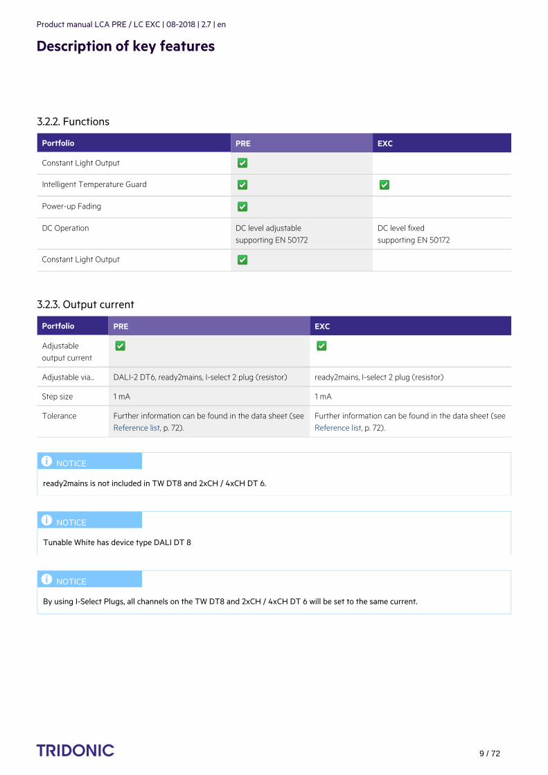
3.2.2. Functions
Portfolio PRE EXC
Constant Light Output
Intelligent Temperature Guard
Power-up Fading
DC Operation DC level adjustablesupporting EN 50172
DC level fixed supporting EN 50172
Constant Light Output
3.2.3. Output current
Portfolio PRE EXC
Adjustableoutput current
Adjustable via... DALI-2 DT6, ready2mains, I-select 2 plug (resistor) ready2mains, I-select 2 plug (resistor)
Step size 1 mA 1 mA
Tolerance Further information can be found in the data sheet (see).Reference list, p. 72
Further information can be found in the data sheet (see).Reference list, p. 72
I NOTICE
ready2mains is not included in TW DT8 and 2xCH / 4xCH DT 6.
I NOTICE
Tunable White has device type DALI DT 8
I NOTICE
By using I-Select Plugs, all channels on the TW DT8 and 2xCH / 4xCH DT 6 will be set to the same current.
Product manual LCA PRE / LC EXC | 08-2018 | 2.7 | en
Description of key features
c 10 / 72
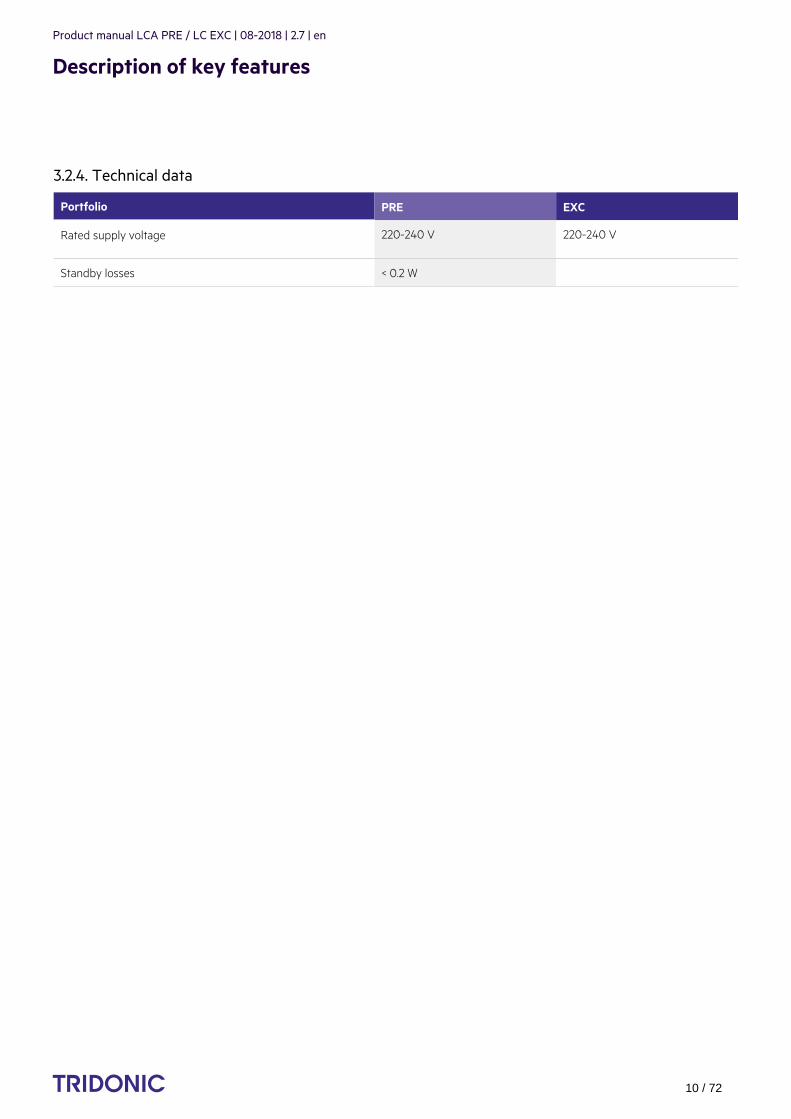
3.2.4. Technical data
Portfolio PRE EXC
Rated supply voltage 220-240 V 220-240 V
Standby losses < 0.2 W
...

Product manual LCA PRE / LC EXC | 08-2018 | 2.7 | en
Description of key features
c 11 / 72
3.3. Housing variantsAll the layers are available in three different housing variants: compact, independent and low profile.
Image Description
Housing variant compact
Housing variant stretched compact
Housing variant independent
Housing variant low profile
Compact shape for installation inside the luminaire casing (in-built)_
Typical area of application: Spotlights, downlights_
Shape that can be used as compact or independent (for an installation outside theluminaire strain relief can be attached to the casing)
_
Typical area of application: Spotlight, downlight_
Long and small shape for installation outside the luminaire casing (remote)_
Typical area of application: Spotlights, Downlights_
Special characteristic: Full loop-through capability of mains and interface (DALI)cables
_
Flat shape for a space-saving installation inside the luminaire casing (in-built)_
Typical area of application: area lighting, linear lighting_
Product manual LCA PRE / LC EXC | 08-2018 | 2.7 | en
Description of key features
c 12 / 72
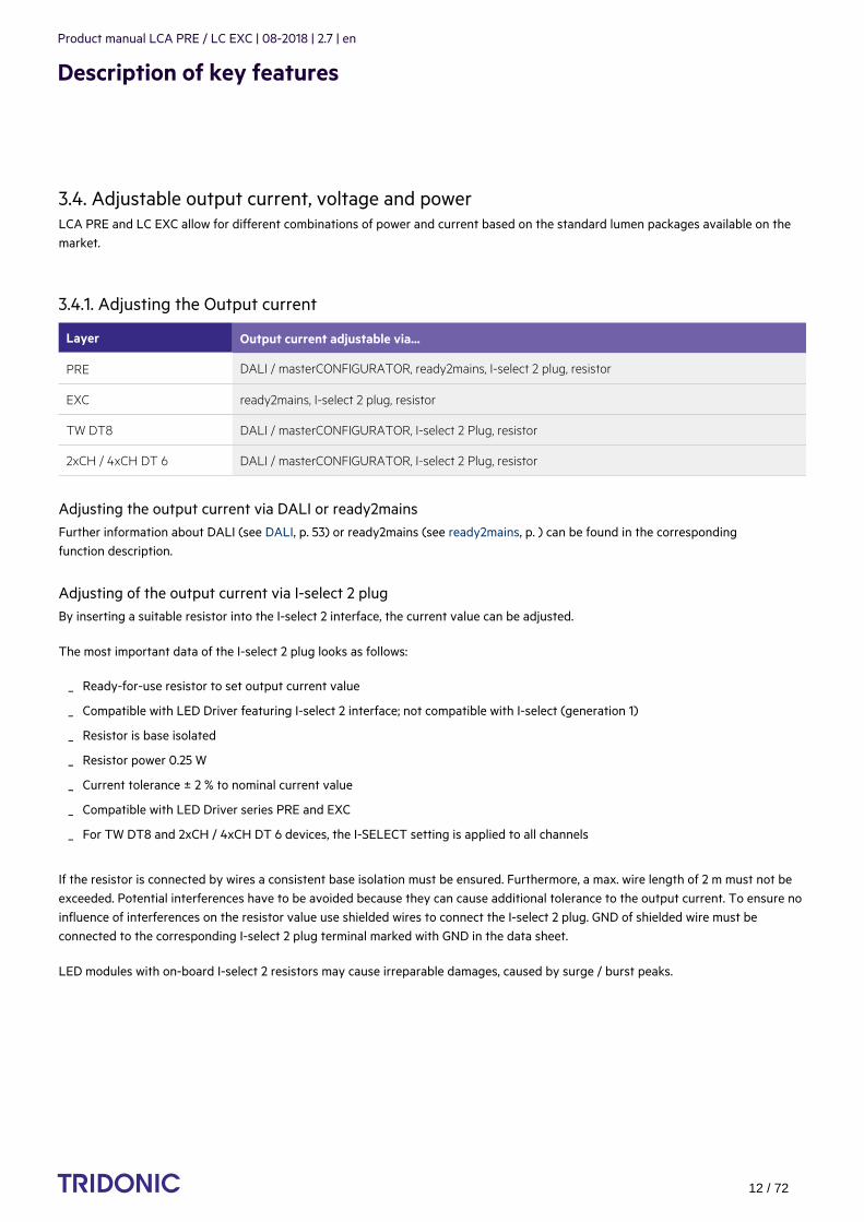
3.4. Adjustable output current, voltage and powerLCA PRE and LC EXC allow for different combinations of power and current based on the standard lumen packages available on themarket.
3.4.1. Adjusting the Output current
Layer Output current adjustable via...
PRE DALI / masterCONFIGURATOR, ready2mains, I-select 2 plug, resistor
EXC ready2mains, I-select 2 plug, resistor
TW DT8 DALI / masterCONFIGURATOR, I-select 2 Plug, resistor
2xCH / 4xCH DT 6 DALI / masterCONFIGURATOR, I-select 2 Plug, resistor
Adjusting the output current via DALI or ready2mainsFurther information about DALI (see ) or ready2mains (see ) can be found in the correspondingDALI, p. 53 ready2mains, p. function description.
Adjusting of the output current via I-select 2 plugBy inserting a suitable resistor into the I-select 2 interface, the current value can be adjusted.
The most important data of the I-select 2 plug looks as follows:
If the resistor is connected by wires a consistent base isolation must be ensured. Furthermore, a max. wire length of 2 m must not beexceeded. Potential interferences have to be avoided because they can cause additional tolerance to the output current. To ensure noinfluence of interferences on the resistor value use shielded wires to connect the I-select 2 plug. GND of shielded wire must beconnected to the corresponding I-select 2 plug terminal marked with GND in the data sheet.
LED modules with on-board I-select 2 resistors may cause irreparable damages, caused by surge / burst peaks.
Ready-for-use resistor to set output current value_
Compatible with LED Driver featuring I-select 2 interface; not compatible with I-select (generation 1)_
Resistor is base isolated_
Resistor power 0.25 W_
Current tolerance ± 2 % to nominal current value_
Compatible with LED Driver series PRE and EXC_
For TW DT8 and 2xCH / 4xCH DT 6 devices, the I-SELECT setting is applied to all channels_

Product manual LCA PRE / LC EXC | 08-2018 | 2.7 | en
Description of key features
c 13 / 72
Adjusting the output current via resistorThe output current of the LED Driver gear can be changed by setting different resistances.The resistance values are taken from theE96 series.
IUnlike DALI and ready2mains which do not generate additional tolerances in the output current, tolerances are higher when using-select 2 plugs.
The relationship between output current and resistor value looks as follows:
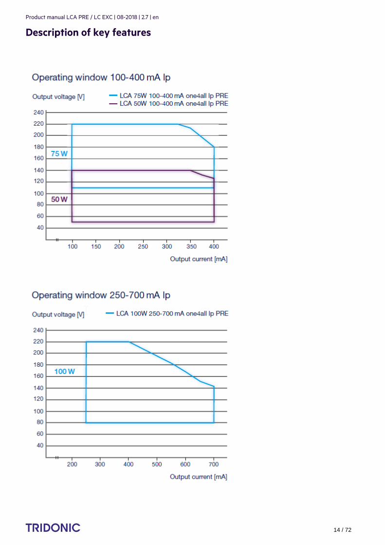
3.4.2. Output voltageThe output voltage range results from the current selected. For more information see the data sheet (see ).Reference list, p. 72The output current can be adjusted via DALI, ready2mains or an I-Select 2 resistor. The diagrams below show the forward voltageranges as a function of the output current and are intended as a guide. For detailed values and an explanation of the methodsavailable please refer to the data sheets.
ready2mains is not supported on our tunable white DT 8 and 2xCH / 4xCH DT 6 devices.
...
I NOTICE
Please note that the resistor values for I-select 2 are not compatible with I-select (generation 1). Installation of an incorrect resistormay cause irreparable damage to the LED module(s).
Resistors for the main output current values can be ordered from Tridonic. Further information about accessories can be found onthe TRIDONIC homepage and in the respective data sheet (see ).Reference list, p. 72
R [k] = 5 V / I_out [mA] x 1,000_
Resistor value tolerance 1 %; resistor power 0.1 W; base isolation necessary_
I NOTICE
The output current tolerance depends on the tolerance of the resistors.
Product manual LCA PRE / LC EXC | 08-2018 | 2.7 | en
Description of key features
c 14 / 72
...

Product manual LCA PRE / LC EXC | 08-2018 | 2.7 | en
Description of key features
c 15 / 72
3.5. Operating Window MultichannelThe new Multichannel devices (DT 8 and 2/4 CH DT 6) differ from the normal standard LED Driver in certain points.They make it possible to use more than one channel at one device. Due to this fact a different view of the operating window waschoosen.All Multichannel devices are equipped with an I-Select 2 Interface. The current set with this plug will be used for all channels with thesame value.
3.5.1. Multichannel – DT8 - LCA 50W 350–1050mA DT8 lp PREThis device has 1 DT8 output.Both channels can be programmed with the max. output current as defined in the datasheet.All multi channel devices are equipped with an I-SELECT 2 Interface. The current set with this plug will be used for all channels withthe same value.The colour can be set via DT8 colour temperature commands and colourSWITCH (see ).colourSWITCH, p.
...

Product manual LCA PRE / LC EXC | 08-2018 | 2.7 | en
Description of key features
c 16 / 72
This graph shows the operating window of the device.
Operating window 100 % Operating window dimmed
This graph shows the output power window of the device.
Operating window 100 % Operating window dimmed

Product manual LCA PRE / LC EXC | 08-2018 | 2.7 | en
Description of key features
c 17 / 72
Make sure that the LED Driver is operated within the given window under all operating conditions. Special attention needs to be paid at dimming and DC emergency operation as the forward voltage of the connected LED modulesvaries with the dimming level, due to the implemented amplitude dimming technology. Coming below the specified minimum output voltage of the LED Driver may cause the device to shut-down.
3.5.2. Multichannel – 2xCH - LCA 50W 350–1050mA 2xCH lp PREThis device has two DT 6 output channels. Both channels can be programmed and operated separately.There are 2 DALI addresses available and every channel can be programmed via DALI with its own current settings. Both channels can be programmed with the max. output current as defined in the datasheet.All Multichannel devices are equipped with an I-Select 2 Interface. The current set with this plug will be used for all channels with thesame value.
This graph shows the operating window of the device.
Operating window 100 % Operating window dimmed
When using both channels, the second graph has to be used because the power of the device will be reduced depending on thecurrent and forward voltage selection.Make sure not to overload the device with high output currents on both channels. Always calculate summary values for current andforward voltage for our used channels.If a wrong setup was stored and the driver would be overloaded, the second Channel (2) will reduce the output power automatically toprotect the device.

Product manual LCA PRE / LC EXC | 08-2018 | 2.7 | en
Description of key features
c 18 / 72
3.5.3. Multichannel – LCA 100W 350–1050mA 2xDT8 lp PREThis device has 2 DT8 outputs.Output 1+2 will be seen as one DT8 channel and ouput 3+4 will be seen as the other DT8 channel.The colour can be set with color temperature commands via DALI.The device has two DT8 DALI addresses. The current can be programmed via DALI for all four output channels with the max. outputcurrent as defined in the datasheet.
All multichannel devices are equipped with an I-Select 2 Interface. The current set with this plug will be used for all channels with thesame value.
...

Product manual LCA PRE / LC EXC | 08-2018 | 2.7 | en
Description of key features
c 19 / 72
This graph shows the operating window of the device.
Operating window 100 % Operating window dimmed
When using both channels, you have to use the second graph, because the power of the device will be reduced depending on yourcurrent and forward voltage selection.Make sure not to overload the device with to high output currents on both channels. Always calculate summary values for current andforward voltage for your used channels.If a wrong setup was stored and the driver would be overloaded, the second output Channel (2) and the fourth output Channel (4) will
automatically to protect the device. reduce the output powerChannel 2+4 is the same colour and so an indication is clearly visible while reducing the output power.
Product manual LCA PRE / LC EXC | 08-2018 | 2.7 | en
Description of key features
c 20 / 72
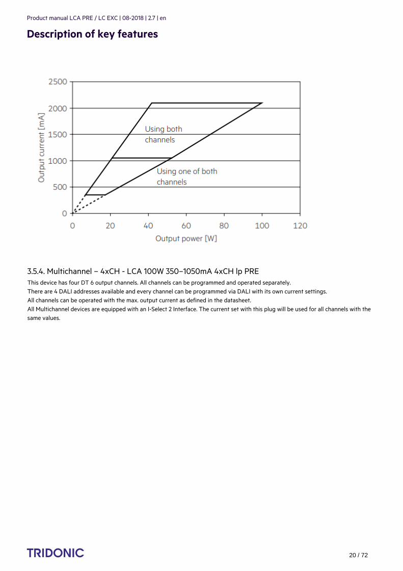
3.5.4. Multichannel – 4xCH - LCA 100W 350–1050mA 4xCH lp PREThis device has four DT 6 output channels. All channels can be programmed and operated separately.There are 4 DALI addresses available and every channel can be programmed via DALI with its own current settings. All channels can be operated with the max. output current as defined in the datasheet.All Multichannel devices are equipped with an I-Select 2 Interface. The current set with this plug will be used for all channels with thesame values.
...
Product manual LCA PRE / LC EXC | 08-2018 | 2.7 | en
Description of key features
c 21 / 72
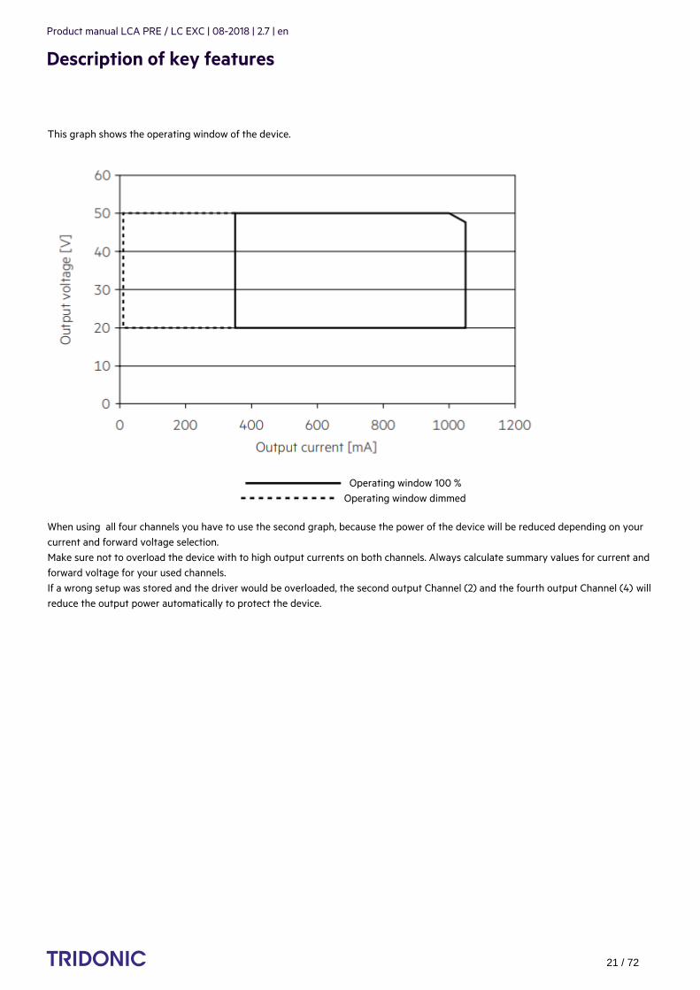
This graph shows the operating window of the device.
Operating window 100 % Operating window dimmed
When using all four channels you have to use the second graph, because the power of the device will be reduced depending on yourcurrent and forward voltage selection.Make sure not to overload the device with to high output currents on both channels. Always calculate summary values for current andforward voltage for your used channels.If a wrong setup was stored and the driver would be overloaded, the second output Channel (2) and the fourth output Channel (4) willreduce the output power automatically to protect the device.
Product manual LCA PRE / LC EXC | 08-2018 | 2.7 | en
Description of key features
c 22 / 72
...
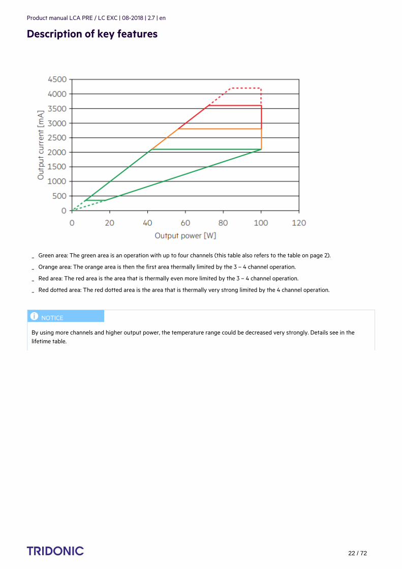
Green area: The green area is an operation with up to four channels (this table also refers to the table on page 2)._
Orange area: The orange area is then the first area thermally limited by the 3 – 4 channel operation._
Red area: The red area is the area that is thermally even more limited by the 3 – 4 channel operation._
Red dotted area: The red dotted area is the area that is thermally very strong limited by the 4 channel operation._
I NOTICE
By using more channels and higher output power, the temperature range could be decreased very strongly. Details see in thelifetime table.

Product manual LCA PRE / LC EXC | 08-2018 | 2.7 | en
Description of key features
c 23 / 72
With increasing performance and use of all channels, the temperature range is severely limited. Details can be taken from the"Expected life-time" table.
Type
Output current (CH1 + CH2 + CH3 +CH4) ta 30 °C 35 °C 40 °C 50 °C 60 °C
LCA 100W 350-1050mA 4xCHlp PRE
700 – 1,400 mA
tc 50 °C 55 °C 60 °C 70 °C 80 °C
Life-time >100,000 h >100,000 h >100,000 h 95,000 h 50,000 h
1,400 – 1,800 mA
tc 55 °C 60 °C 65 °C 75 °C 85 °C
Life-time >100,000 h >100,000 h >100,000 h 50,000 h 25,000 h
1,800 – 2,100 mA
tc 60 °C 65 °C 70 °C 80 °C 90 °C
Life-time >100,000 h 90,000 h 65,000 h 40,000 h 25,000 h
2,100 – 2,800 mA
tc 60 °C 65 °C 70 °C 85 °C -
Life-time 80,000 h 55,000 h 40,000 h 20,000 h -
2,800 – 3,600 mA
tc 65 °C 70 °C 75 °C - -
Life-time 40,000 h 30,000 h 20,000 h - -
3,600 – 4,200 mA
tc 70 °C 75 °C - - -
Life-time 20,000 h 15,000 h - - -
...

Product manual LCA PRE / LC EXC | 08-2018 | 2.7 | en
Compatibility between module and LED Driver
c 24 / 72
There are two stages involved in the check for compatibility between the LED module and the LED Driver.
4.1. Comparison of data sheet values with a 4-point guidelineDifferent values for the two devices need to be considered when comparing the data sheets. The following table shows which valuesare involved and which requirements they must meet.
Comparisonof…
Value inlight module
Value in LEDDriver Detailed procedure
(1) Current Imax = Outputcurrent
continue... ->
Max. DCforwardcurrent
>= Outputcurrent +tolerances
...
The requirements for operating together can be checked by comparing the data sheets_
Subsequent practical tests can ensure that there are no unexpected problems during actual operation_
Determine forward current of LED module_
Check whether LED Driver can be operated with the same outputcurrent
_
Check whether max. DC forward current of LED module is greater thanor equal to output current of LED Driver (including tolerances)
_
½ CAUTION!
The max. DC forward current can be temperature dependent!Refer to the derating curve of the LED module data sheet (see Reference
).list, p. 72

Product manual LCA PRE / LC EXC | 08-2018 | 2.7 | en
Compatibility between module and LED Driver
c 25 / 72
Comparisonof…
Value inlight module
Value in LEDDriver Detailed procedure
(2) Voltage Min. forwardvoltage
> Min. outputvoltage
Max. forwardvoltage
< Max. outputvoltage
Min. forwardvoltage
@ min.dimlevel
> Min. outputvoltage
(3) LFcurrentripple
Max.permissible LFcurrent ripple
>= Output LFcurrent ripple(<120Hz)
(4) Max.peak current
Max.permissible
peak current
> Max. outputcurrent peak
...
Check whether voltage range of LED module is completely within thevoltage range of LED Driver
_
½ CAUTION!
!The forward voltage is temperature dependentRefer to the Vf/t diagram in the data sheet (see ).p Reference list, p. 72
I NOTICE
To ensure full dimming performance the forward voltage of the LEDmodule at min. dim level must be greater than or equal to the min. outputvoltage of the driver.
Determine the forward voltage of the LED module at lowest dim level_
In case there is no data available for the LED module at lowest dimlevel: take the min. forward voltage minus 20 % as an approximation
_
Check whether the forward voltage of the LED module is greater thanor equal to the min. output voltage of the driver
_
Check whether max. permissible LF current ripple of LED module isgreater than or equal to output LF current ripple of LED Driver
_
Check whether max. permissible peak current of LED module is greaterthan max. output current peak of LED Driver
_

Product manual LCA PRE / LC EXC | 08-2018 | 2.7 | en
Compatibility between module and LED Driver
c 26 / 72
4.2. Application of the 4-point guidelineThe compatibility check with the 4-point guideline is shown here using two examples.
4.2.1. Example 1
Comparison data for LED Driver
LED Driver
Designation LCI 20W 350mA-900mA TOP C
Manufacturer TRIDONIC
Data sheet values of LED Driver
Output current 500 mA
Output current tolerance ± 5 %
Min. output voltage 18 V (1)
Max. output voltage 40 V (1)
Output LF current ripple ± 2 %
Max. output current peak 600 mA
(1) Values at 500mA

Product manual LCA PRE / LC EXC | 08-2018 | 2.7 | en
Compatibility between module and LED Driver
c 27 / 72
Comparison data for LED module
LED module
Designation Fictitious LED module
Manufacturer Other manufacturer
Data sheet values of LED module
Forward current 500 mA
Max. DC forward current 1,050 mA
Typ. forward voltage 33 V ±10 % (1)
Min. forward voltage 29.7 V (1)
Max. forward voltage 36.3 V (1)
Max. permissible LF current ripple 630 mA
Max. permissible peak current 1,500 mA
(1) Values at 500mA
Questions
...
Are the two components mutually compatible?_
Can the required luminous flux of 1,510 lm be achieved with this combination?_
Product manual LCA PRE / LC EXC | 08-2018 | 2.7 | en
Compatibility between module and LED Driver
c 28 / 72
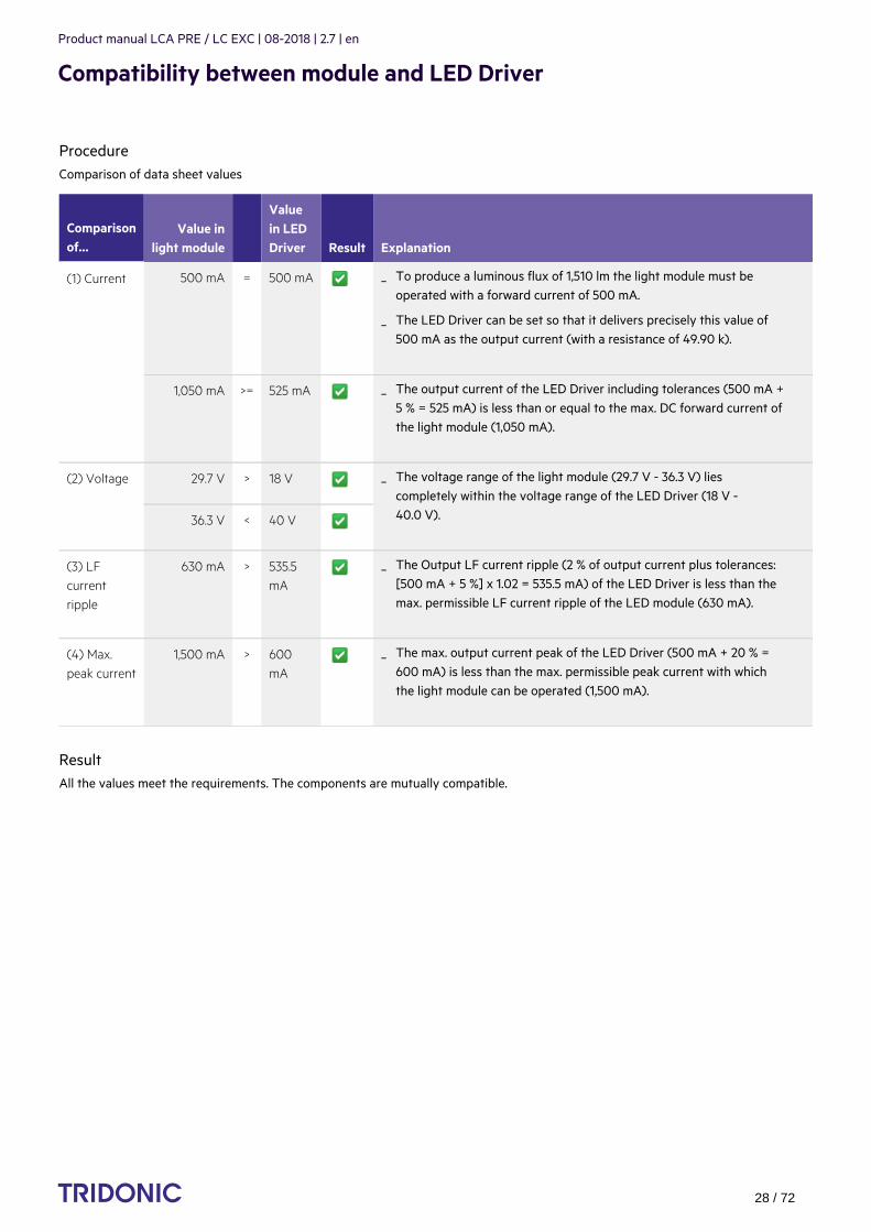
ProcedureComparison of data sheet values
Comparisonof…
Value inlight module
Valuein LEDDriver Result Explanation
(1) Current 500 mA = 500 mA
1,050 mA >= 525 mA
(2) Voltage 29.7 V > 18 V
36.3 V < 40 V
(3) LFcurrentripple
630 mA > 535.5mA
(4) Max.peak current
1,500 mA > 600mA
ResultAll the values meet the requirements. The components are mutually compatible.
To produce a luminous flux of 1,510 lm the light module must beoperated with a forward current of 500 mA.
_
The LED Driver can be set so that it delivers precisely this value of500 mA as the output current (with a resistance of 49.90 k).
_
The output current of the LED Driver including tolerances (500 mA +5 % = 525 mA) is less than or equal to the max. DC forward current ofthe light module (1,050 mA).
_
The voltage range of the light module (29.7 V - 36.3 V) liescompletely within the voltage range of the LED Driver (18 V -40.0 V).
_
The Output LF current ripple (2 % of output current plus tolerances:[500 mA + 5 %] x 1.02 = 535.5 mA) of the LED Driver is less than themax. permissible LF current ripple of the LED module (630 mA).
_
The max. output current peak of the LED Driver (500 mA + 20 % =600 mA) is less than the max. permissible peak current with whichthe light module can be operated (1,500 mA).
_

Product manual LCA PRE / LC EXC | 08-2018 | 2.7 | en
Compatibility between module and LED Driver
c 29 / 72
4.2.2. Example 2
Comparison data for LED Driver
LED Driver
Designation LCI 20W 350mA-900mA TOP C
Manufacturer TRIDONIC
Data sheet values of LED Driver
Output current 500 mA
Output current tolerance ± 5 %
Min. output voltage 18 V (1)
Max. output voltage 40 V (1)
Output LF current ripple ± 2 %
Max. output current peak 600 mA
(1) Values at 500mA
Comparison data for LED module
LED module
Designation Fictitious LED module
Manufacturer Other manufacturer
Data sheet values of LED module
Forward current 500 mA
Max. DC forward current 1,050 mA
Typ. forward voltage 39.5 V ±10 % (1)
Min. forward voltage 35.55 V (1)
Max. forward voltage 43.45 V (1)
Max. permissible LF current ripple 630 mA
Max. permissible peak current 1,500 mA
(1) Values at 500mA

Product manual LCA PRE / LC EXC | 08-2018 | 2.7 | en
Compatibility between module and LED Driver
c 30 / 72
Questions
...
Are the two components mutually compatible?_
Can the required luminous flux of 1,800 lm be achieved with this combination?_

Product manual LCA PRE / LC EXC | 08-2018 | 2.7 | en
Compatibility between module and LED Driver
c 31 / 72
ProcedureComparison of data sheet values
Comparisonof…
Value inlight module
Valuein LEDDriver Result Explanation
(1) Current 500 mA = 500 mA
1,050 mA >= 525 mA
(2) Voltage 35.55 V > 18 V
43.45 V < 40 V
(3) LFcurrentripple
630 mA > 535.5mA
(4) Max.peak current
1,500 mA > 600 mA
ResultOne of the values meet the requirements. The components are mutually compatible.does not not
...
To produce a luminous flux of 1,800 lm the light module must beoperated with a forward current of 500 mA.
_
The LED Driver can be set so that it delivers precisely this value of500 mA as the output current (with a resistance of 49.90 k).
_
The output current of the LED Driver including tolerances (500 mA +5 % = 525 mA) is less than or equal to the max. DC forward current ofthe light module (1,050 mA).
_
The voltage range of the light module (35.55 V - 43.45 V) is notwithin the voltage range of the LED Driver (18 V - 40.0 V)
_
The Output LF current ripple (2 % of output current plus tolerances:[500 mA + 5 %] x 1.02 = 535.5 mA) of the LED Driver is less than themax. permissible LF current ripple of the LED module (630 mA).
_
The max. output current peak of the LED Driver (500 mA + 20 % =600 mA) is less than the max. permissible peak current with whichthe light module can be operated (1,500 mA).
_

Product manual LCA PRE / LC EXC | 08-2018 | 2.7 | en
Compatibility between module and LED Driver
c 32 / 72
4.3. Practical testsPractical tests are used to ensure fault-free operation of the light module and LED Driver. The following aspects must be checked.
4.3.1. Technical aspects
4.3.2. Visual aspects
4.3.3. ConditionsWhen conducting the tests the following conditions must be considered:
...
Transient behaviour_
Colour shift_
Connection during operation_
Parasitic capacitance_
Flickering_
Stroboscopic effect (video applications)_
Dimming behaviour_
Colour change/stability_
Luminous flux_
All tolerances_
Entire temperature range_
Different output voltage ranges (incl. no load)_
Entire dimming range_
Short circuit_
I NOTICE
If the values are slightly over or under the specified threshold values or if there are any other concerns or questions please contactTechnical Support: [email protected]

Product manual LCA PRE / LC EXC | 08-2018 | 2.7 | en
Installation notes
c 33 / 72
5.1. Safety information
...
I NOTICE
The cabling, wiring and mounting for a LED driver varies depending on the design and manufacturer of the LED module.The following description should therefore not be viewed as comprehensive installation instructions but merely as importantgeneral information.
To obtain further information, proceed as follows:
Read the documentation provided by the lamp manufacturer. Follow the guidelines and instructions of the lampmanufacturer!
_
Observe all relevant standards. Follow the instructions given in the standards!_
½ WARNING!
Comply with the general safety instructions (see ) !General safety instructions, p. 5_
To avoid failures due to ground faults protect the wiring against mechanical loads from sharp-edged metal parts (e.g. cablepenetrations, cable holders, metal frames, etc.
_
Electronic LED Driver from Tridonic are protected for a maximum of 48 hour against overvoltage of up to 320 V. Make surethat the LED Driver is not exposed to overvoltages for long periods!
_
Electronic LED Driver LCA PRE, LC EXC from Tridonic have type of protection IP 20. Comply with the requirements for thistype of protection!
_

Product manual LCA PRE / LC EXC | 08-2018 | 2.7 | en
Installation notes
c 34 / 72
5.2. Function of the earth terminal
The earth connection is conducted as protection earth (PE). The LED Driver can be earthed via earth terminal or metal housing (ifdevice has metal housing). If the LED Driver will be earthed, protection earth (PE) has to be used. There is no earth connectionrequired for the functionality of the LED Driver. Earth connection is recommended to improve following behaviour.
In general it is recommended to earth the LED Driver if the LED module is mounted on earthed luminaire parts respectively heat sinksand thereby representing a high capacity against earth.
5.2.1. Avoiding residual LED glow on standbyResidual LED glow on standby may occur as a result of capacitive leakage currents from the LED module onto earthed luminaire parts(such as the heat sink). This mainly affects high-efficiency LED systems with large surface areas installed in luminaires with protectionclass 1.
The topology has been improved so that residual LED glow can be virtually eliminated by earthing the devices.
5.2.2. Avoiding the transfer of mains transients to the LED outputThe transfer of mains transients to the LED output presents a problem for many LED driver topologies currently on the market, andTRIDONIC devices may be affected.
Voltage peaks at the input of the LED driver may be transferred to the output of the device where they lead to differences in potentialbetween the LED output and earthed luminaire parts. These differences in potential may result in flashovers if the insulation isinadequate or if the creepage and clearance distances are too small. Flashovers will cause the LED module to fail.
Earthing the LED driver attenuates voltage peaks and reduces the likelihood of flashovers. The precise degree of attenuation dependson the capacitance of the LED module with respect to earth. If voltages at the output are higher than 0.5 kV, it is mentioned in thedata sheet.
Electromagnetic interferences (EMI)_
LED glowing at standby_
Transmission of mains transients to the LED output_
I NOTICE
If the LED driver cannot be earthed or if earthing is not desired, residual LED glow can be minimised by adequate insulation (forexample by using heat-conducting double-sided insulation foil).
Product manual LCA PRE / LC EXC | 08-2018 | 2.7 | en
Installation notes
c 35 / 72
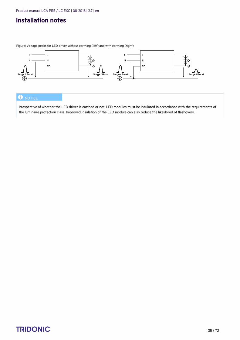
Figure: Voltage peaks for LED driver without earthing (left) and with earthing (right)
...
I NOTICE
Irrespective of whether the LED driver is earthed or not, LED modules must be insulated in accordance with the requirements ofthe luminaire protection class. Improved insulation of the LED module can also reduce the likelihood of flashovers.

Product manual LCA PRE / LC EXC | 08-2018 | 2.7 | en
Installation notes
c 36 / 72
5.3. Routing the wires
5.3.1. Tests
5.3.2. Insulation and dielectric strength testing of luminairesLED driver for lamps are sensitive to high-voltage transients. This must be taken into consideration when subjecting luminaires toroutine testing during manufacture.
According to IEC 60598-1 Annex Q (for information only!) and ENEC 303-Annex A, each luminaire should be subjected to an insulationtest for 1 second at 500 V DC. The test voltage is applied between the linked phase/neutral conductor terminal and the protectiveearth terminal. The insulation resistance must be at least 2 MOhm.
As an alternative to measuring the insulation resistance, IEC 60598-1 Annex Q describes a dielectric strength test at 1500 V AC (or1.414 x 1,500 V DC). To avoid damaging electronic LED Driver, this dielectric strength test should be performed exclusively for typetesting. This test should certainly not be used for routine testing.
5.3.3. Type testingType testing of the luminaire is performed according to IEC 60598-1 Section 10.The wiring for protection class 1 luminaires is tested at a voltage of 2xU + 1,000 V. In order not to overload the LED Driver all theinputs and outputs of the LED Driver are connected to one another.U is used for measuring the voltage for luminaires with LED Driver with U > 250 V:out out
For U 480 V the voltage for the type test is 2000 V. (Routine testing is always performed at 500 V DC)out
5.3.4. Wiring
I NOTICE
The performance of the prescribed tests and compliance with relevant standards are the responsibility of the luminairemanufacturer.The following descriptions merely indicate the most important tests and are no substitute for a full research of the relevantstandards.
I NOTICE
Tridonic recommends performing an insulation test because a dielectric strength test may damage the device irreparably.
I NOTICE
The wiring procedure is device specific. Further information about wiring, wire cross sections and the length of stripped offinsulation can be found in the data sheet.

Product manual LCA PRE / LC EXC | 08-2018 | 2.7 | en
Installation notes
c 37 / 72
Wiring guidelines
Wiring the plug-in terminal
Detaching the plug-in terminal
5.4. External fuse for DC operationThe internal fuse of an LED Driver is not rated for DC operation. Because of this, an additional external fuse must be used if an LEDDriver is operated on a DC network.
Proceed as follows:
For LED Drivers with a power of 25-150 watts the following values are recommended:
Tridonic recommends the following external fuse:
The cables should be run separately from the mains connections and mains cables to ensure good EMC conditions._
The LED wiring should be kept as short as possible to ensure good EMC. The max. secondary cable length is 2 m (4 m circuit),this applies for LED output as well as for I-select and temperature sensor.
_
Depending on the design of the luminaire it may be possible to improve the radio interference properties by earthing thedevice at the earth connection.
_
The LED driver has no inverse-polarity protection on the secondary side. Wrong polarity can damage LED modules with noinverse-polarity protection.
_
Use solid wire or stranded wire with the correct cross-section_
Strip off correct length of insulation; you may need to twist the tool slightly_
If stranded wire is used: push onto the terminal from above to be able to insert the wire_
Insert the bare end into the terminal_
Push onto the terminal from above to release the wire_
Pull out the wire at the front_
Connect the external fuse to the line labeled "+" which is between the DC power supply and the input terminal of the LEDDriver
_
Only use an external fuse with suitable parameters._
Rated voltage: 250 V_
DC rated power: 1 A - 3 A Time-Lag (SLO-Blo®)_
477 Series, 5 × 20 mm, Time-Lag (Slo-Blo®) Fuse Rating 3.15 A_

Product manual LCA PRE / LC EXC | 08-2018 | 2.7 | en
Installation notes
c 38 / 72
5.5. Maximum loading of circuit breakers
5.5.1. Importance of maximum loadingA circuit breaker is an automatically operated electrical switch that protects an electrical circuit from damage caused by overload orshort circuit. Unlike a fuse that must be replaced if it triggers, a circuit breaker can be reset (either manually or automatically) andused further. Circuit breakers are available in different sizes and with different technical data.
The inrush current is a short increased peak current that occurs when an electronic control gear is switched on.
In electrical installations, numerous control gear are connected to one circuit breaker. The maximum loading of a circuit breakerindicates how many control gear can be connected to the circuit breaker without triggering the circuit breaker because of thesummation of the different inrush currents. The value is calculated through simulation programs based on the circuit breakerscharacteristic.
Information about the maximum loading can be found in Tridonic data sheets. The following table shows the data for LCA 50W100-400mA one4all lp PRE as an example
Automatic circuit breaker type C10 C13 C16 C20 B10 B13 B16 B20 Inrush current
Installation Ø 1.5mm2
1.5mm2
2.5mm2
2.5mm2
1.5mm2
1.5 mm2
2.5mm2
2.5mm2
Imax time
LCA 50W 100-400mA one4all lp PRE 18 26 28 34 9 13 14 17 22.4 A 176 µs
5.5.2. Calculation of maximum loading
Tripping characteristics of circuit breakersThe load at which a circuit breaker triggers is defined by the height and the duration of the applied current. The following table shows exemplary values for different circuit breakers (B10, B13, B16, B20).
Duration[s]
Current B10[A ]peak
Current B13[A ]peak
Current B16[A ]peak
Current B20[A ]peak
100 700 910 1,120 1,400
200 260 338 416 520
300 177 230.1 283 354
400 145 188.5 232 290
500 122 158.6 195 244
600 110 143 176 220
700 102 132.6 163 204
Product manual LCA PRE / LC EXC | 08-2018 | 2.7 | en
Installation notes
c 39 / 72
800 97 126.1 155 194
900 93 120.9 149 186
1000 90 117 144 180
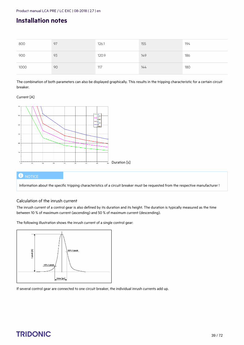
The combination of both parameters can also be displayed graphically. This results in the tripping characteristic for a certain circuitbreaker.
Current [A]
Duration [s]
Calculation of the inrush currentThe inrush current of a control gear is also defined by its duration and its height. The duration is typically measured as the timebetween 10 % of maximum current (ascending) and 50 % of maximum current (descending).
The following illustration shows the inrush current of a single control gear:
If several control gear are connected to one circuit breaker, the individual inrush currents add up.
I NOTICE
Information about the specific tripping characteristics of a circuit breaker must be requested from the respective manufacturer !
Product manual LCA PRE / LC EXC | 08-2018 | 2.7 | en
Installation notes
c 40 / 72
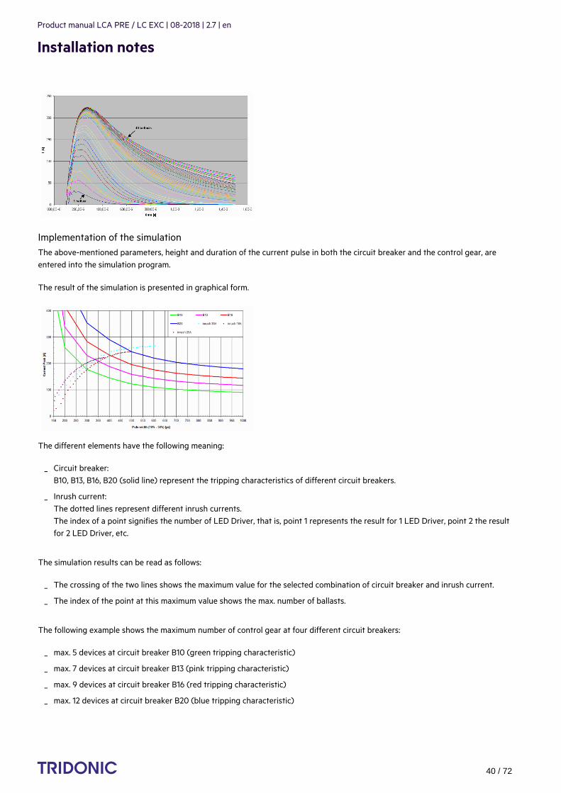
Implementation of the simulationThe above-mentioned parameters, height and duration of the current pulse in both the circuit breaker and the control gear, areentered into the simulation program.
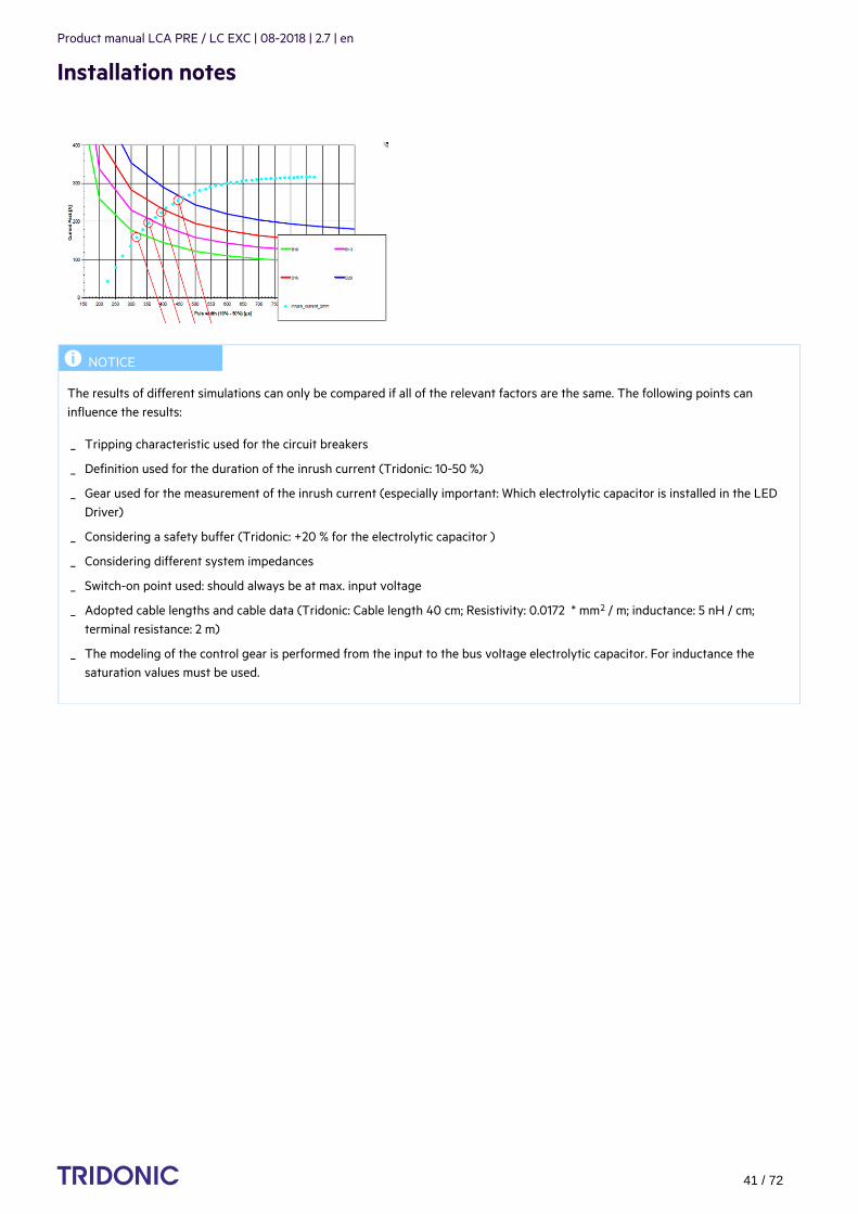
The result of the simulation is presented in graphical form.
The different elements have the following meaning:
The simulation results can be read as follows:
The following example shows the maximum number of control gear at four different circuit breakers:
Circuit breaker:B10, B13, B16, B20 (solid line) represent the tripping characteristics of different circuit breakers.
_
Inrush current:The dotted lines represent different inrush currents.The index of a point signifies the number of LED Driver, that is, point 1 represents the result for 1 LED Driver, point 2 the resultfor 2 LED Driver, etc.
_
The crossing of the two lines shows the maximum value for the selected combination of circuit breaker and inrush current._
The index of the point at this maximum value shows the max. number of ballasts._
max. 5 devices at circuit breaker B10 (green tripping characteristic)_
max. 7 devices at circuit breaker B13 (pink tripping characteristic)_
max. 9 devices at circuit breaker B16 (red tripping characteristic)_
max. 12 devices at circuit breaker B20 (blue tripping characteristic)_
Product manual LCA PRE / LC EXC | 08-2018 | 2.7 | en
Installation notes
c 41 / 72
...
I NOTICE
The results of different simulations can only be compared if all of the relevant factors are the same. The following points caninfluence the results:
Tripping characteristic used for the circuit breakers_
Definition used for the duration of the inrush current (Tridonic: 10-50 %)_
Gear used for the measurement of the inrush current (especially important: Which electrolytic capacitor is installed in the LEDDriver)
_
Considering a safety buffer (Tridonic: +20 % for the electrolytic capacitor )_
Considering different system impedances_
Switch-on point used: should always be at max. input voltage_
Adopted cable lengths and cable data (Tridonic: Cable length 40 cm; Resistivity: 0.0172 * mm / m; inductance: 5 nH / cm;2
terminal resistance: 2 m)_
The modeling of the control gear is performed from the input to the bus voltage electrolytic capacitor. For inductance thesaturation values must be used.
_

Product manual LCA PRE / LC EXC | 08-2018 | 2.7 | en
Functions
c 42 / 72
1.
2.
3.
4.
5.
6.
6.1. corridorFUNCTION V2 (PRE only)
6.1.1. DescriptionThe corridorFUNCTION enables the illuminance to be linked to the presence or absence of people. A conventional relay motion sensoris connected. The luminous intensity is increased when a person enters the room. When the person leaves the room the motion sensorswitches off after a certain delay and the luminous intensity is automatically reduced.
The corridorFUNCTION is particularly beneficial in applications in which light is needed round the clock for safety reasons, forexample in public buildings, large apartment complexes, car parks, pedestrian underpasses and underground railway stations. Sincethe luminous intensity only has to be increased when there is a demand for light the corridorFUNCTION offers effective lightingmanagement and helps saving energy and costs. Another benefit of the corridorFUNCTION is the enhanced convenience of automaticlighting control.
Profile settings:Standard profile for activating via 230V on the interface terminal DA/N - DA/L for 5 minutes is "Never off"
The LED Drivers have different profiles so they can provide the best possible performance in a range of conditions. The profiles aredefined by a series of values:
Fade-in time: the time that starts as soon as the presence of a person is detected. During the fade-in time the luminous intensityis faded up to the presence value (default: 0s).
Run-on time: the time that starts as soon as the presence of a person is no longer detected. If the presence of a person isdetected again during the run-on time the run-on time is restarted from zero. If no presence is detected during the run-on timethe fade time is started as soon as the run-on time expires.
Fade time: the time during which the luminous intensity is faded from the presence value to the absence value (default: 30 s).
Switch off delay: the time during which the absence value is held before the lighting is switched off. Depending on the profileselected the switch-off delay may have different values or may not be defined (default: "Never Off").
Absence value: the luminous intensity when there is no person present (default: 10 %).
Presence value: the luminous intensity when persons are present (default: 100 %).
½ CAUTION!
To ensure correct operation a sinusoidal mains voltage with a frequency of 50 Hz or 60 Hz is required at the control input.Special attention must be paid to achieving clear zero crossings. Serious mains faults may impair the operation of switchDIM andcorridorFUNCTION.

Product manual LCA PRE / LC EXC | 08-2018 | 2.7 | en
Functions
c 43 / 72
Variable switch-off times
The profiles and their values can be freely adjusted. The values can be adjusted via a connection to a DALI bus.
6.1.2. Commissioning
Activating the corridorFUNCTION
Procedure by means of the mains voltage
Activating the corridorFUNCTION is simple. If an a.c. voltage of 230 V is applied to the digital interface of the LED Driver for a periodof at least 5 minutes the LED Driver detects the corridorFUNCTION and automatically activates it. Activation is required only once perdevice.There are three procedures for activating by means of the mains voltage. The requirements are the same in each case.
Requirements:
Procedure Version 1:
Procedure Version 2:
Procedure Version 3: Only possible if the motion sensor offers a manual override option
Procedure via the masterCONFIGURATOR
The corridorFUNCTION can also be activated via the masterCONFIGURATOR.
Further information can be found in the masterCONFIGURATOR manual (see ).Reference list, p. 72
The LED Driver is correctly installed in the luminaire_
Input voltage is applied_
A motion sensor is connected to information DA/N or DA/L_
Remain in the activation range of the motion sensor for more than 5 minutes-> The motion sensor detects movement and switches on-> The corridorFUNCTION is activated automatically after 5 minutes-> The light value switches to presence level (default: 100 %)
_
Set the run-on time on the motion sensor to a value greater than 5 minutes_
Remain in the activation range of the motion sensor for a short time-> The motion sensor detects movement and switches on-> The corridorFUNCTION is activated automatically after 5 minutes-> The light value switches to presence value (default: 100 %)
_
Reset the run-on time of the motion sensor to the required value_
Set the slide switch on the motion sensor to the "Never-Off" function_
Wait 5 minutes-> The corridorFUNCTION is activated automatically after 5 minutes-> The light value switches to presence value (default: 100 %)
_
Reset the slide switch on the motion sensor to the "automatic" function_

Product manual LCA PRE / LC EXC | 08-2018 | 2.7 | en
Functions
c 44 / 72
Deactivating the corridorFUNCTIONIf the corridorFUNCTION is activated the LED Driver is controlled only by motion. To operate the LED Driver via DALI, DSI orswitchDIM the corridorFUNCTION must be deactivated.
Procedure via mains
Procedure via DALI/DSI
Procedure via masterCONFIGURATOR
If the corridorFUNCTION was activated via the masterCONFIGURATOR it can be deactivated as follows:
Adjusting the values of the corridorFUNCTIONThe values of the corridorFUNCTION can be individually adjusted. The values are set via a DALI USB on the bus and by enteringspecial DALI commands via the masterCONFIGURATOR.
Further information can be found in the masterCONFIGURATOR manual (see ).Reference list, p. 72
...
Connect mains voltage push button to the terminal marked DA/L_
Connect neutral conductor to the terminal marked DA/N_
Press the push button 5 times within 3 seconds_
Send 5 DALI or DSI commands within 3 seconds to the LED Driver_
Send 5 DALI or DSI commands within 3 seconds to the LED Driver_

Product manual LCA PRE / LC EXC | 08-2018 | 2.7 | en
Functions
c 45 / 72
6.1.3. Installation
Requirements:
Procedure:
Wiring versions:
The LED Driver is correctly installed in the luminaire and cabled on the power supply side_
A motion sensor is installed in the lighting system_
The motion sensor is connected to the LED Driver_
Connect the neutral conductor (N) to terminal DA/N on the LED Driver_
Connect the output of the motion sensor (switched phase) to terminal DA/L on the LED Driver_

Product manual LCA PRE / LC EXC | 08-2018 | 2.7 | en
Functions
c 46 / 72
Benefits:
Control can be changed at any time to a digital control signal (DSI or DALI) without having to change the luminaire or provide anadditional control line
...
½ CAUTION!
Use conventional relay motion sensors!Electronic motion sensors (Triac) are not suitable because of their technical design.
½ CAUTION!
Do not use glow switches!Glow switches may affect the control.
½ CAUTION!
Make sure that the control line (L') of the motion sensor is connected to terminal DA/L and the neutral conductor (N) to terminalDA/N.
½ CAUTION!
For five-pole wiring the neutral conductor must be connected to DA/N. This prevents 400 V being applied between adjacent terminals if a different phase is used for the control input.
I NOTICE
For large installations, supply to the LED Driver may be split among several phases (L1, L2, L3).Any phase can be used for the control input .Any number of motion sensors can be connected in parallel.

Product manual LCA PRE / LC EXC | 08-2018 | 2.7 | en
Functions
c 47 / 72
6.2. DSI (PRE only)
6.2.1. DescriptionDSI (Digital Serial Interface) enables DSI control gear to be controlled. The DSI line can be wired separately via a two-core cable ortogether with the mains cable in a five-core cable. Communication is not impaired by the mains cable. In contrast to DALI, there is noindividual addressing of the ballasts with DSI.
DSI offers a series of benefits:
The main benefits of DSI are the optimisation of energy consumption of extensive groups of luminaires (e.g. in sports stadiums andfactories).
6.2.2. Commissioning
Further information can be found in the DALI Handbook (see ).Reference list, p. 72
...
Expansion options via submodules, for example in combination with daylight control or additional switch modules_
Wiring: Simple wiring with five pole standard cables and line length of up to 250 metres_
Wiring: Polarity-free control lines can be used for mains and control lines_
Wiring: Multiple wiring possibilities (star, series and mixed wiring)_
Unaffected by electrical interference: Uniform light level from the first to the last light source_
reverse polarity protected connection: can be connected with any polarity_
I NOTICE
If the corridorFUNCTION is activated the LED Driver is controlled only by motion. To operate the LED Driver via DALI, DSI orswitchDIM the corridorFUNCTION must be deactivated.

Product manual LCA PRE / LC EXC | 08-2018 | 2.7 | en
Functions
c 48 / 72
6.3. switchDIM (PRE only)
6.3.1. DescriptionWith the switchDIM function it is possible to use the mains voltage as a control signal.The phase of a simple standard mains voltage push button is connected to the terminal marked DA/L and the neutral conductor isconnected to the terminal marked DA/N.
Using the function is easy and convenient:
switchDIM is therefore a very simple form of lighting management. It also has a positive effect on material and labour costs.
The device has a switchDIM memory function. This is used, among other things, for storing the last dimming value in the event ofinterruptions in the power supply.When power returns, the LED is automatically restored to its previous operating state and dimmed to the last value.
6.3.2. Commissioning
Using the switchDIM functionswitchDIM is operated by the mains voltage push button.
A short press (50-600 ms) switches the device on or off_
A long press (> 600 ms) fades the connected operating device alternately up and down (between 1 and 100 %)._
½ CAUTION!
Glow switches are not approved for controlling switchDIM.Glow switches may cause the LED Driver to spontaneously switch on or off or make sudden changes in the dimming value.
½ CAUTION!
To ensure correct operation a sinusoidal mains voltage with a frequency of 50 Hz or 60 Hz is required at the terminal.Special attention must be paid to achieving clear zero crossings. Serious mains faults may impair the operation of switchDIM andcorridorFUNCTION.
½ CAUTIONS!
A maximum number of 25 operating devices per switchDIM system should not be exceeded.If you have more devices please use DALI or DSI.
I NOTICE
If the corridorFUNCTION is activated the LED Driver is controlled only by motion. To operate the LED Driver via DALI, DSI orswitchDIM the corridorFUNCTION must be deactivated.
Product manual LCA PRE / LC EXC | 08-2018 | 2.7 | en
Functions
c 49 / 72
Procedure:
Synchronising devicesIf the devices in a system do not operate synchronously the devices must be synchronised, i.e. put in the same status (on/off).
Procedure:
Changing the fading timeThe default value for the fading time is approx. 3 seconds. It can be changed to approx. 6 seconds.
Procedure:
Switching the LED Driver to automatic mode In automatic mode the device detects which control signal (DALI, DSI, switchDIM, etc.) is connected and automatically switches to the
corresponding operating mode.
Procedure:
6.3.3. Installation
Wiring variantsThere are two options for installing switchDIM: four-pole and five-pole wiring
Switch the device on/off by briefly actuating the push button or_
Dim the device by holding down the push button_
Hold down the push button for 10 seconds-> All devices will be synchronised to the same status-> LEDs will will be set to a uniform light value (approx. 50 %) -> The fading time will be set to it default value (approx. 3 seconds)
_
Hold down the push button for 20 seconds-> After 10 seconds: all devices will be synchronised to the same status-> After 20 seconds: a fading time of approx. 6 seconds will be set-> LEDs will be set to a uniform light value (approx. 100 %)
_
Press the push button 5 times within 3 seconds_

Product manual LCA PRE / LC EXC | 08-2018 | 2.7 | en
Functions
c 50 / 72
Four-pole wiring
Configuration:
Phase (L), neutral (N), earth (PE), control line (L')
Benefits:
No need for a control line thanks to bridging terminal 8 and the N-connection of the luminaire
Five-pole wiring
Configuration:
Phase (L), neutral (N), earth (PE), control line (L), neutral (N)
Benefits:
Control can be changed at any time to a digital control signal (DSI or DALI) without having to change the luminaire or provide anadditional control line

Product manual LCA PRE / LC EXC | 08-2018 | 2.7 | en
Functions
c 51 / 72
...
½ CAUTION!
For five-pole wiring the neutral conductor must be connected to DA/N. This prevents 400 V being applied between adjacent terminals if a different phase is used for the control input.

Product manual LCA PRE / LC EXC | 08-2018 | 2.7 | en
Functions
c 52 / 72
6.4. Power-up Fading (PRE only)
6.4.1. DescriptionThe power-up fading function offers the opportunity to realise a soft start. The soft start will be applied at turning on the mains andat starts by switchDIM. The function is programmed as a DALI fade time in the range from 0.7 to 16 seconds and dims in the selectedtime from 0% to the power-on level.
By factory default power-up fading is not active (0 seconds).
6.4.2. Commissioning
Procedure via the masterCONFIGURATOR
Further information can be found in the masterCONFIGURATOR manual (see ).Reference list, p. 72
...
Open dialog box "Tridonic-specific configuration"_
Click tab "Power-up Fading"_
Choose value from drop-down menu "Power-up Fading"_
Click "save"-> Changes are saved
_
Product manual LCA PRE / LC EXC | 08-2018 | 2.7 | en
Functions
c 53 / 72
6.5. DALI (PRE only)
6.5.1. Description
DALI standard
DALI (Digital Addressable Lighting Interface) is an interface protocol for digital communication between electronic lightingequipment.
The DALI standard was developed by Tridonic together with renowned manufacturers of operating and control equipment. Today,these manufacturers belong to the DALI Activity Group which promotes the use and further development of DALI.
The DALI standard is defined in IEC 62386. A test procedure standardised by the DALI Activity Group ensures compatibility betweenproducts from different manufacturers. Tridonic products have undergone this test and meet all the requirements. This is indicated bythe logo of the DALI Activity Group on the device.
The agreement by the lighting industry to adopt a common protocol has opened up a virtually unlimited number of options. With theright choice of individual DALI components an extremely wide range of requirements can be met, from operating a simple light switchto lighting management systems for entire office complexes with thousands of light sources.
DALI in ActionDALI offers a lot of possibilities:
Technical data of a DALI line:
I NOTICE
LCA PRE devices support the new DALI standard V2 (according to EN 62386-102).
DALI line: 64 LED Driver can be grouped to a line_
DALI groups: Every LED Driver can be attributed into 16 groups_
Addressability: All LED Driver are individually addressable_
Grouping: Possible without complicated rewiring_
Programmability: Individual programmability makes it possible to use functions which transcend the DALI standard_
Monitoring: Easily possible thanks to status feedback_
Wiring: Simple wiring with five pole standard cables and a cable length of max. 300 metres_
Wiring: Polarity-free control lines can be used for mains and control lines_
Wiring: Multiple wiring possibilities (star, series and mixed wiring)_
Unaffected by interruptions: All luminaires receive the same, unaffected digital signal and dimming level_
Similar light level from first to last luminaire_
DALI voltage: 9.5 V - 22.4 DC_
Maximum DALI system current: max. 250 mA_
Data transfer rate: 1200 Baud_
Maximum line length: up to 300 m (for 1,5 mm )2_

Product manual LCA PRE / LC EXC | 08-2018 | 2.7 | en
Functions
c 54 / 72
6.5.2. Commissioning
Further information can be found in the DALI Handbook (see ).Reference list, p. 72
eDeD ("enhanced DALI") offers extended DALI commands. They can be used to activate specific commands of the LED Driver. ThemasterCONFIGURATOR software works with eD commands. These commands are Tridonic specific. They are not part of the DALIstandard and are not publicly available.
...
I NOTICE
If the corridorFUNCTION is activated the LED Driver is controlled only by motion. To operate the LED Driver via DALI, DSI orswitchDIM the corridorFUNCTION must be deactivated.
Product manual LCA PRE / LC EXC | 08-2018 | 2.7 | en
Functions
c 55 / 72
6.6. ready2mains
6.6.1. Description ready2mains uses the mains cable to transmit information: easily, reliably and professionally.
Luminaires are controlled and dimmed directly via the mains, with no need for any additional wiring. ready2mains can be used toconfigure both drivers with a separate communication interface as well as fixed output drivers. The configuration saves time and isvery flexibel. ready2mains reduces production costs and installation costs and also reduces possible sources of error.
6.6.2. Dimmingready2mains allows for mains-based group dimming, controlled via the ready2mains protocol and appropriate dimming interfaces. Fordetails on the operation of ready2mains and its components see the relevant technical information.
6.6.3. ConfigurationThe ready2mains interface can be used to configure the main parameters of LED Drivers via the mains wiring (LED output current,CLO and DC level for LCA PRE; LED output current for LC EXC). These parameters can be adjusted either via ready2mains-capableconfiguration software or directly via the ready2mains programmer (output current only). Further information can be found inthe Leaflet ready2mains (see ).Reference list, p. 72
...
Easy refurbishment of dimmable and non-dimmable installations_
No rewiring within the ceilings_
Allows cost-effective solutions_
Easy configuration of luminaires_
Simple integration in existing test setups_
Product manual LCA PRE / LC EXC | 08-2018 | 2.7 | en
Functions
c 56 / 72
6.7. Constant Light Output (PRE only)
6.7.1. DescriptionThe light output of an LED module reduces over the course of its life. The Constant Light Output function compensates for thisnatural decline by constantly increasing the output current of the LED Driver throughout its life. As a results, a virtually uniform lightoutput is achieved at all times.
For configuration purposes the expected module-specific values for lifetime and residual luminous flux must be specified. The outputcurrent is then controlled automatically on the basis of these values. The LED Driver typically starts with an output current ("Required Intensity") that corresponds to the expected residual luminous fluxand calculates the increase in the value on the basis of the anticipated lifetime.
If the OTL function is enabled, visual feedback is given as soon as the LED exceeds the expected LED lamp life. If the expected LEDlamp life is exceeded, the luminaire flashes for 2 seconds after being switched on.
6.7.2. Commissioning
Procedure via the masterCONFIGURATOR
Activating the Constant Light Output function
Activating the Over the Lifetime function
I NOTICE
To be able to adjust the parameters "Required intensity", "LED burning hours" and "Expected LED life" the "Advanced settings"must be activated. Further information can be found in the masterCONFIGURATOR manual (see ).Reference list, p. 72
Open dialog box "Tridonic-specific configuration"_
Click tab "CLO and OTL"_
Set drop-down menu "Constant intensity" to "enabled"_
Click "save"-> Changes are saved
_
Open dialog box "Tridonic-specific configuration"_
Click tab "CLO und OTL"_
Set drop-down menu "Visual feedback" to "enabled"_
Click "save"-> Changes are saved
_

Product manual LCA PRE / LC EXC | 08-2018 | 2.7 | en
Functions
c 57 / 72
Setting Required intensity and Expected LED life
Transferring existing values to a new LED Driver
If a control gear is replaced the existing parameter values can be transferred to the new LED Driver.
Replacing the LED module
If an LED module is replaced the parameter "LED burning hours" must be set to "0".
Further information can be found in the masterCONFIGURATOR manual (see ).Reference list, p. 72
...
Open dialog box "Tridonic-specific configuration"_
Click tab "CLO and OTL"_
Enter values in input fields "Required intensity" and "Expected LED life"_
Click "save"-> Changes are saved
_
Chose a control gear that is in the same room as the new control gear_
Open dialog box "Tridonic-specific configuration"_
Click tab "CLO and OTL"_
Note down the values for "Required intensity", "LED burning hours" and "Expected LED life"_
Close dialog box "Tridonic-specific configuration"_
Chose the new control gear_
Open dialog box "Tridonic-specific configuration"_
Click tab "CLO and OTL"_
Take the noted values and enter them in the input fields "Required intensity", "LED burning hours" and "Expected LED life"_
Click "save"-> Changes are saved
_
Open dialog box "Tridonic-specific configuration"_
Click tab "CLO and OTL"_
Delete value from input field "LED burning hours"-> CLO function is automatically restarted-> Changes are saved
_

Product manual LCA PRE / LC EXC | 08-2018 | 2.7 | en
Functions
c 58 / 72
6.8. DC recognition
6.8.1. DescriptionIn emergency light systems with central battery supply the DC recognition function uses the input voltage to detect that emergencymode is in place. The LED Driver then automatically switches to DC mode and dims the light to the defined DC level. Without DCrecognition different and more complex solutions need to be applied in order to detect emergency mode.
6.8.2. CommissioningThe function is integrated in the device as standard. No additional commissioning is necessary for activation.
...
LED Driver of the LCA PRE series are factory preset to a DC level of 15 %. This value can be customised. Further informationcan be found in the masterCONFIGURATOR manual (see ).Reference list, p. 72
_
LED Driver of the LC EXC series have different DC levels. Further information can be found in the data sheet of thecorresponding LED Driver (see ).Reference list, p. 72
_
I NOTICE
The LED Driver is designed to operate on DC voltage and pulsing DC voltage.In DC recognition connected sensors are ignored.
Product manual LCA PRE / LC EXC | 08-2018 | 2.7 | en
Functions
c 59 / 72
6.9. Dimming on DC (PRE only)
6.9.1. DescriptionIf Dimming on DC is activated the requirements of the DC recognition function are ignored. Even if DC is detected the LED Drivercontinues to behave as in AC mode:
6.9.2. Commissioning
Procedure with masterCONFIGURATORFurther information can be found in the masterCONFIGURATOR manual (see ).Reference list, p. 72
...
The present dimming level is retained_
An emergency light level defined for the DC recognition function (DC level) is ignored_
Control signals via DALI und DSI continue to be executed_
½ WARNING!
If Dimming on DC is activated then emergency mode is not recognised. The device no longer automatically switches to theemergency light level.Make sure that if Dimming on DC is activated an appropriate dimming level is selected for the emergency lighting mode.
Please also note the following:
Dimming on DC may only be activated by trained personnel_
A security code must be entered before activation_
The security code is issued only after a consent form has been signed_
Dimming on DC must not be used in emergency lighting systems to EN 50172_

Product manual LCA PRE / LC EXC | 08-2018 | 2.7 | en
Functions
c 60 / 72
6.10. Intelligent Temperature Guard
6.10.1. DescriptionThe Intelligent Temperature Guard function provides protection against temporary thermal overloads. It slowly reduces the output ifthe maximum T temperature is exceeded. This way instant failure of the LED Driver can be prevented. Thermal overload protection isc
triggered as soon as the T temperature is exceeded by around 5 to 10 °C. The precise trigger temperature depends on the device.c
The value is selected so that the protection function is not performed until there is a significant impact on rated life.
The output is reduced in small stages that are generally imperceptible to the user. The temperature is checked every two minutes.
6.10.2. BehaviourThe following table shows the exact behaviour and parameters of the Intelligent Temperature Guard function for LCA PRE and LCEXC
Parameters Description
Start of power reduction When maximum operating temperature (Tc) is exceeded by approx. 5-10 °C (1)
Power reduction rate Reduction of max level by 1 dim step / 2 min
Power reduction processand control
Power reduction is dependent on temperature:
Min power level ca. 50 % dim level (2)
Shut off behaviour No shut off behaviour:Device will not shut off if temperature still rises.
½ WARNING!
The T temperature is the maximum permitted in terms of safety.c
Operating the LED Drivers above the permitted T temperature is not compliant with relevant standards.c
The Intelligent Temperature Guard function does not replace the proper thermal design of the luminaire and does not enable thelighting to operate for lengthy periods of time in impermissible ambient temperatures.
Power reduction continues if temperature still rises_
Power reduction stops if temperature does not rise anymore or if maximum power reduction isreached (minimum power level = 50 %)
_
If temperature falls below a certain level, power is increased again until 100 % is reached_
If temperature still rises even if maximum power reduction is reached:_PRE drivers go to 15 % dim level_
EXC drivers go to minimum dim level_
AC mode: Device switches to 15 % dimming level for PRE and to minimum dim level for EXC_
DC mode: Intelligent Temperature Guard is not relevant because driver goes to EOFx levelanyway
_
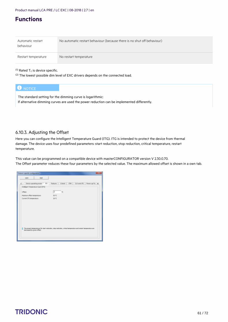
Product manual LCA PRE / LC EXC | 08-2018 | 2.7 | en
Functions
c 61 / 72
Automatic restartbehaviour
No automatic restart behaviour (because there is no shut off behaviour)
Restart temperature No restart temperature
(1) Rated T is device specific.c
The lowest possible dim level of EXC drivers depends on the connected load.(2)
6.10.3. Adjusting the OffsetHere you can configure the Intelligent Temperature Guard (ITG). ITG is intended to protect the device from thermaldamage. The device uses four predefined parameters: start reduction, stop reduction, critical temperature, restarttemperature.
This value can be programmed on a compatible device with masterCONFIGURATOR version V 2.30.0.70.The Offset parameter reduces these four parameters by the selected value. The maximum allowed offset is shown in a own tab.
...
I NOTICE
The standard setting for the dimming curve is logarithmic:If alternative dimming curves are used the power reduction can be implemented differently.
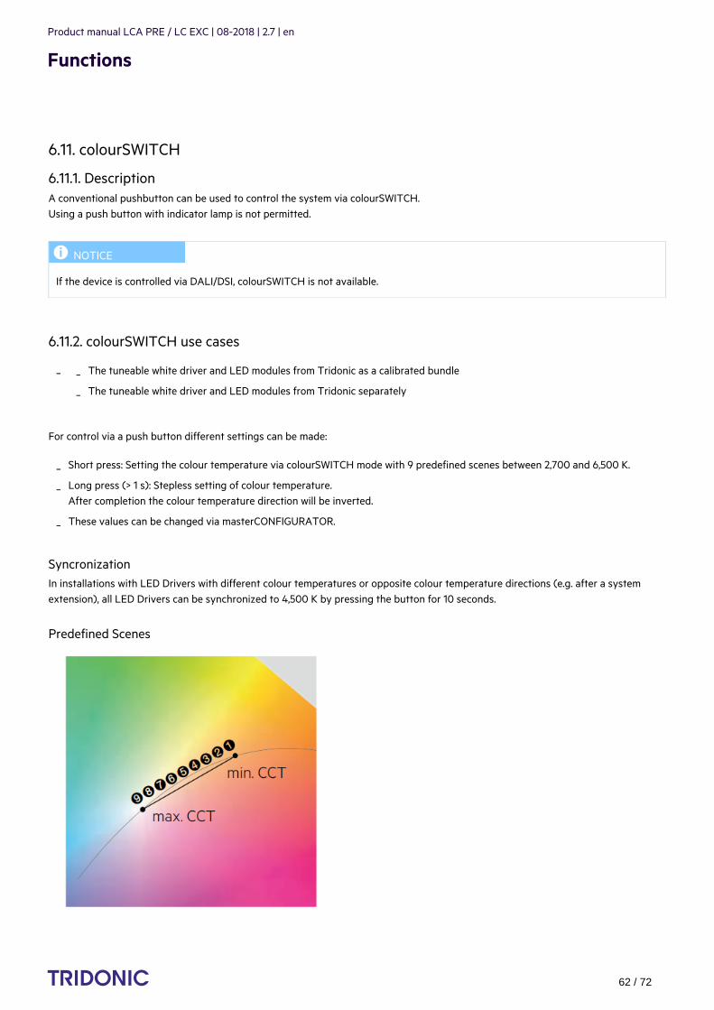
Product manual LCA PRE / LC EXC | 08-2018 | 2.7 | en
Functions
c 62 / 72
6.11. colourSWITCH
6.11.1. DescriptionA conventional pushbutton can be used to control the system via colourSWITCH. Using a push button with indicator lamp is not permitted.
6.11.2. colourSWITCH use cases
For control via a push button different settings can be made:
SyncronizationIn installations with LED Drivers with different colour temperatures or opposite colour temperature directions (e.g. after a systemextension), all LED Drivers can be synchronized to 4,500 K by pressing the button for 10 seconds.
Predefined Scenes
I NOTICE
If the device is controlled via DALI/DSI, colourSWITCH is not available.
_ The tuneable white driver and LED modules from Tridonic as a calibrated bundle_
The tuneable white driver and LED modules from Tridonic separately_
Short press: Setting the colour temperature via colourSWITCH mode with 9 predefined scenes between 2,700 and 6,500 K._
Long press (> 1 s): Stepless setting of colour temperature.After completion the colour temperature direction will be inverted.
_
These values can be changed via masterCONFIGURATOR._

Product manual LCA PRE / LC EXC | 08-2018 | 2.7 | en
Functions
c 63 / 72
Wiring diagram
Short press behaviourA short press provides the user the possibility to switch between different CCT (correlated color tempterature) values, which arestored as special scenes.
If at least one long press is in between two short presses, the next short press shall recall the current CCT value instead of continuingwith the next CCT value.
There shall be no reaction on short press if the gear is in standby mode (lamp is off).
Long press behaviourAt a long press, the gear shall fade the CCT using the actual colourSWITCH fade rate. The intensity shall not be changed due to a long press.
At each short press the next CCT value (= next scene) shall be set without fading._
If the last CCT value (= last scene) is reached the next short press shall continue with the first CCT value (= first scene)_
CCT values = MASK shall be skipped - the next Non-MASK value shall be set (could be also the first scene)_
I NOTICE
The default starting CCT value shall be the 4 CCT value (= scene 4) in the list (per default 4,000 K).th
default direction is from warm (default = 2,700 K) to cool (default = 6,500 K)_
each long press the direction of colour fading shall toggles_
after sync press the fade direction shall be always the default direction_
no reaction on long press if the gear is in standby mode (lamp is off)f_

Product manual LCA PRE / LC EXC | 08-2018 | 2.7 | en
Functions
c 64 / 72
Sync press behaviourAt any sync press of switchDIM or colourSWITCH, the gear will be set to default again on both functions!
Fade press behaviourAt any fade press (longer than 20 seconds) of switchDIM or colourSWITCH the colourSWITCH fading time will be set to 5 seconds.Likewise the fade press and also a sync press shall be applied to both switchDIM and colourSWITCH.
Memory Colour ValueOnce the device is in colourSWITCH mode the current CCT value and the currently selected scene number shall be stored atpower-down. These settings shall be recalled at the next power-on. For the very first power-on (no Memory CCT) the default settingsshall be applied.
Configuration and default settings
colourSWITCH fade rate Definition
default ca. 2,5s from 2700K to 6500K and vice versa, longer if CCT range is bigger
slow ca. 5s from 2700K to 6500K and vice versa, longer if CCT range is bigger
Scene no. CCT value Scene no. CCT value
1 0x0A8C (= 2,700 K) 6 0x1388 (= 5,000 K)
2 0x0BB8 (= 3,000 K) 7 0x157C (= 5,500 K)
3 0x0DAC (= 3,500 K) 8 0x1770 (= 6,000 K)
4 (default) 0x0FA0 (= 4,000 K) 9 0x1964 (= 6,500 K)
5 0x1194 (= 4,500 K) 10 0xFFFF (MASK)
6.11.3. colourSWITCH modecolourSWITCH is not a separate one4all mode but a functional extension to switchDIM mode.
This means:
The CCT value shall be set according to the 4 CCT value (= scene 4)th_
The direction of CCT fading for the next long press is set from warm to cool_
The colourSWITCH fade rate shall be set to default_
switchDIM is set to default (according sync press specification of switchDIM)_
The colourSWITCH fading time will be set to default (2.5 s)_
switchDIM is set to default (according to sync press specification of switchDIM)_
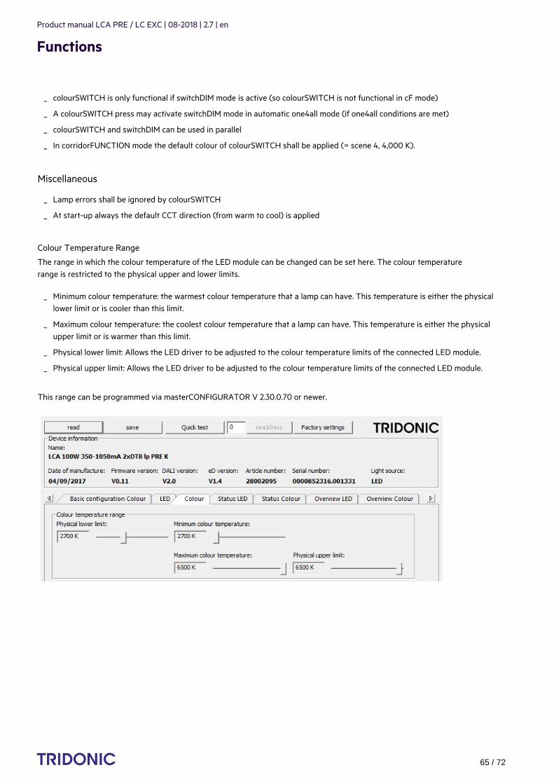
Product manual LCA PRE / LC EXC | 08-2018 | 2.7 | en
Functions
c 65 / 72
Miscellaneous
Colour Temperature Range
The range in which the colour temperature of the LED module can be changed can be set here. The colour temperaturerange is restricted to the physical upper and lower limits.
This range can be programmed via masterCONFIGURATOR V 2.30.0.70 or newer.
...
colourSWITCH is only functional if switchDIM mode is active (so colourSWITCH is not functional in cF mode)_
A colourSWITCH press may activate switchDIM mode in automatic one4all mode (if one4all conditions are met)_
colourSWITCH and switchDIM can be used in parallel_
In corridorFUNCTION mode the default colour of colourSWITCH shall be applied (= scene 4, 4,000 K)._
Lamp errors shall be ignored by colourSWITCH_
At start-up always the default CCT direction (from warm to cool) is applied_
Minimum colour temperature: the warmest colour temperature that a lamp can have. This temperature is either the physicallower limit or is cooler than this limit.
_
Maximum colour temperature: the coolest colour temperature that a lamp can have. This temperature is either the physicalupper limit or is warmer than this limit.
_
Physical lower limit: Allows the LED driver to be adjusted to the colour temperature limits of the connected LED module._
Physical upper limit: Allows the LED driver to be adjusted to the colour temperature limits of the connected LED module._

Product manual LCA PRE / LC EXC | 08-2018 | 2.7 | en
Functions
c 66 / 72
6.12. proportionSWITCH
6.12.1. DescriptionA conventional push button can be used to control the system via proportionSWITCH. Using a of push button with indicator lamp isnot permitted.
6.12.2. proportionSWITCH use cases
For control via pushbutton, different settings can be made:
In installations with LED Drivers with different dimming level or opposite dimming direction (e.g. after a system extension), all LEDDrivers can be synchronized to a standard value by a 10 seconds push.
I NOTICE
If the device is controlled via DALI/DSI, proportionSWITCH is not available.
For proportionSWITCH use cases a tuneable white device and the use of colourSWITCH is proposed. Theoretically it is also possible with static white driver and proportionSWITCH as well but the colour and dim performance isvery limited
_
Static driver with DT6 and possibility to individually dim direct and indirect light_
Short press: Setting of 5 pre-defined light levels (variable for each channel for direct and indirect applications).A maximum of 10 scenes can be programmed.
_
Long press (> 1 s): Stepless setting of dimming level. Both channels running in opposite directionAfter completion, the dimming direction of both channels will be inverted.Values can be changed via masterCONFIGURATOR.
_
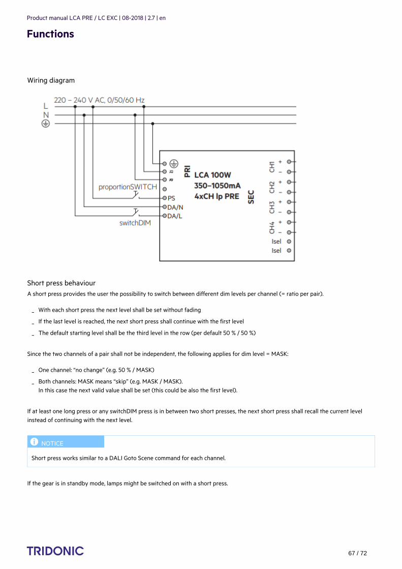
Product manual LCA PRE / LC EXC | 08-2018 | 2.7 | en
Functions
c 67 / 72
Wiring diagram
Short press behaviourA short press provides the user the possibility to switch between different dim levels per channel (= ratio per pair).
Since the two channels of a pair shall not be independent, the following applies for dim level = MASK:
If at least one long press or any switchDIM press is in between two short presses, the next short press shall recall the current levelinstead of continuing with the next level.
If the gear is in standby mode, lamps might be switched on with a short press.
With each short press the next level shall be set without fading_
If the last level is reached, the next short press shall continue with the first level_
The default starting level shall be the third level in the row (per default 50 % / 50 %)_
One channel: “no change” (e.g. 50 % / MASK)_
Both channels: MASK means “skip” (e.g. MASK / MASK). In this case the next valid value shall be set (this could be also the first level).
_
I NOTICE
Short press works similar to a DALI Goto Scene command for each channel.

Product manual LCA PRE / LC EXC | 08-2018 | 2.7 | en
Functions
c 68 / 72
Long press behaviour
If the gear is in standby mode, lamps shall be switched on with a long press using the default direction; this means:channel 1 and 3 (on 4 channel devices) dims up to 100% and channel 2 and 4 (on 4 channel devices) stays at Physical Mimimum Level(PHM)
Sync press behaviour:
Fade press behaviourAt any fade press of switchDIM or proportionSWITCH the switchDIM fading time shall be set to fast (5 seconds).Likewise the fade press and also a sync press shall be applied to both switchDIM and proportionSWITCH.
Memory levelOnce the device is in proportionSWITCH mode, the current dim level and the currently selected ratio shall be stored at power-down.These settings shall be recalled at the next power-on.
For the very first power-on (no memory dim level), the default settings shall be applied.
...
With a long press, the gear shall fade both channels up or down_
opposite direction using the actual switchDIM fade rate_
The direction of fading of each channel will toggle_
The default direction shall be upwards for 4 channel device channel 1 + 3 (= logical unit 1) and downwards for channel 2 + 4 (=logical unit 2)
_
With a sync press the fade direction shall be always the default direction_
Once one channel reaches its physical minimum or maximum level at a long press the corresponding channel stops dimming._
The other channel will continue dimming if the minimum or maximum isn’t reached at the same time_
With a sync press of switchDIM or proportionSWITCH, the gear shall be set to default again_
The dim level (ratio) setting shall be set to the third level for the next short press_
The dimming fade rate is set to default (2.5 seconds)_
The direction of dim level fading for the next long press shall be upwards for channel 1 + 3 (on 4 channel devcies) anddownwards for channel 2 + 4 (on 4 channel devices)
_
switchDIM fade rate shall be set to default_
The dim level after a sync press is 50 % for both channels, according to the switchDIM specification_
A sync press of proportionSWITCH shall synchronise switchDIM as well switchDIM._

Product manual LCA PRE / LC EXC | 08-2018 | 2.7 | en
Functions
c 69 / 72
Configuration and default settings
switchDIM fade rate Definition
default 2 DSI steps per mains period ( = ca. 2.5 s from 1 % to 100 % and vice versa)
slow 1 DSI steps per mains period ( = ca. 5 s from 1 % to 100 % and vice versa)
Level no. Level CH1 Level CH2 Level no. Level CH1 Level CH2
1 254 (100 %) PHM* 6 255 (MASK) 255 (MASK)
2 241 (70 %) 210 (30 %) 7 255 (MASK) 255 (MASK)
3 (default) 229 (50 %) 229 (50 %) 8 255 (MASK) 255 (MASK)
4 210 (30 %) 241 (70 %) 9 255 (MASK) 255 (MASK)
5 PHM* 254 (100 %) 10 255 (MASK) 255 (MASK)
* PHM (physical minimum level)
6.12.3. proportionSWITCH ModeproportionSWITCH is not a separate one4all mode, but a functional extension to switchDIM mode.This means:
6.12.4. proportionSWITCH programmingThe scenes for proportionSWITCH can be programmed via masterCONFIGURATOR.
proportionSWITCH is only functional if switchDIM mode is active (so proportionSWITCH is not functional in corridor mode)_
A proportionSWITCH press may activate switchDIM mode in automatic one4all mode (if one4all conditions are met)_
If proportionSWITCH and switchDIM are pressed in parallel switchDIM has priority (proportionSWITCH not functional)_

Product manual LCA PRE / LC EXC | 08-2018 | 2.7 | en
Functions
c 70 / 72
...
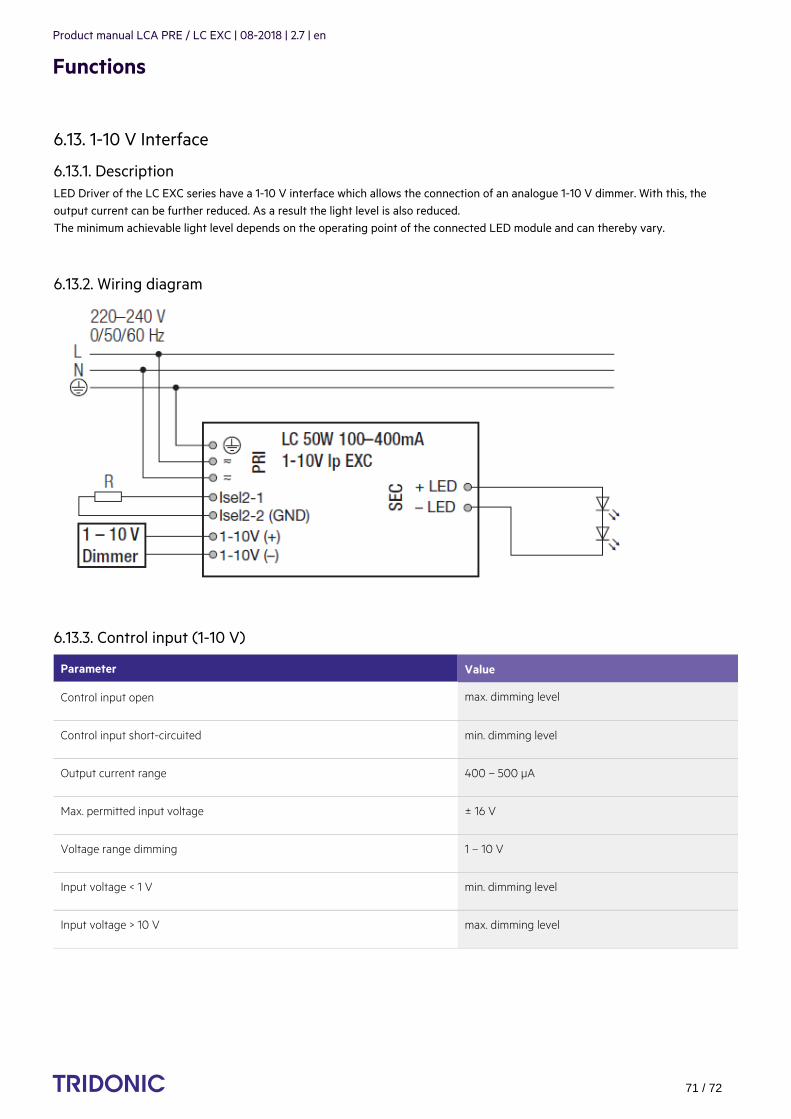
Product manual LCA PRE / LC EXC | 08-2018 | 2.7 | en
Functions
c 71 / 72
6.13. 1-10 V Interface
6.13.1. DescriptionLED Driver of the LC EXC series have a 1-10 V interface which allows the connection of an analogue 1-10 V dimmer. With this, theoutput current can be further reduced. As a result the light level is also reduced.The minimum achievable light level depends on the operating point of the connected LED module and can thereby vary.
6.13.2. Wiring diagram
6.13.3. Control input (1-10 V)
Parameter Value
Control input open max. dimming level
Control input short-circuited min. dimming level
Output current range 400 – 500 µA
Max. permitted input voltage ± 16 V
Voltage range dimming 1 – 10 V
Input voltage < 1 V min. dimming level
Input voltage > 10 V max. dimming level
...

Product manual LCA PRE / LC EXC | 08-2018 | 2.7 | en
Reference list
c 72 / 72
7.1. Additional information
7.2. Downloads
7.3. Technical data
Web page PREMIUM series (Compact dimming): http://www.tridonic.com/com/en/products/led-drivers-compact-dimming-premium.asp
_
Web page EXCITE series (Compact fixed output): http://www.tridonic.com/com/en/products/led-drivers-compact-fixed-output-excite.asp
_
Data sheets: Go to above web page link and click "Products" > "Downloads" > "Data sheet"_
Accessories: Go to above web page link and click "Products" > "Downloads" > "Accessories"_
DALI manual: http://www.tridonic.com/com/en/download/technical/DALI-manual_en.pdf_
Documentation masterCONFIGURATOR: http://www.tridonic.com/com/en/download/Manual_masterConfigurator_en.pdf
_
Leaflet ready2mains:http://www.tridonic.com/com/en/download/brochures/Leaflet_ready2mains_EN_web.pdf
_
Web page corridorFUNCTION: http://www.corridorfunction.com/corridorFUNCTION/index.html_
Tridonic software: http://www.tridonic.com/com/en/software.asp_
Download masterCONFIGURATOR: http://www.tridonic.com/com/de/software-masterconfigurator.asp_
Data sheets: http://www.tridonic.com/com/en/data-sheets.asp_
Company certificates: http://www.tridonic.com/com/en/company-certificates.asp_
Environmental declarations: http://www.tridonic.com/com/en/environmental-declarations.asp_
LED/lamp matrix: http://www.tridonic.com/com/en/lamp-matrix.asp_
Operating instructions: http://www.tridonic.com/com/en/operating-instructions.asp_
Other technical documents: http://www.tridonic.com/com/en/technical-docs.asp_
Tender text: http://www.tridonic.com/com/en/tender.asp_
Declarations of conformity: Available documents are found on each product page of our website in the "Certificates" tab forthe specific product, www.tridonic.com/com/en/products.asp
_