lecturer: tae-hyong kim (d132) [email protected] ch.2 direct link networks computer networks
TRANSCRIPT
2
How to connect hosts physically? Suitable medium Framing Encoding Media access control Error Detection Reliable Delivery
Problem: Physically Problem: Physically Connecting HostsConnecting Hosts
3
Signals Sine Wave Ti me & Frequency Domain Composite Signals Digital Signals Shannon Capacity
Hardware Building Blocks Encoding Framing Error Detection Reliable Transmission Project #1 Ethernet Wireless Assignment #2
ContentsContents
4
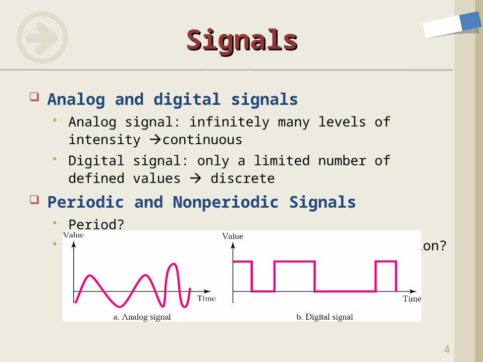
Analog and digital signals Analog signal: infinitely many levels of intensity
continuous Digital signal: only a limited number of defined values
discrete
Periodic and Nonperiodic Signals Period? What signals can be used for data transmission?
SignalsSignals
5
Sine WaveSine Wave
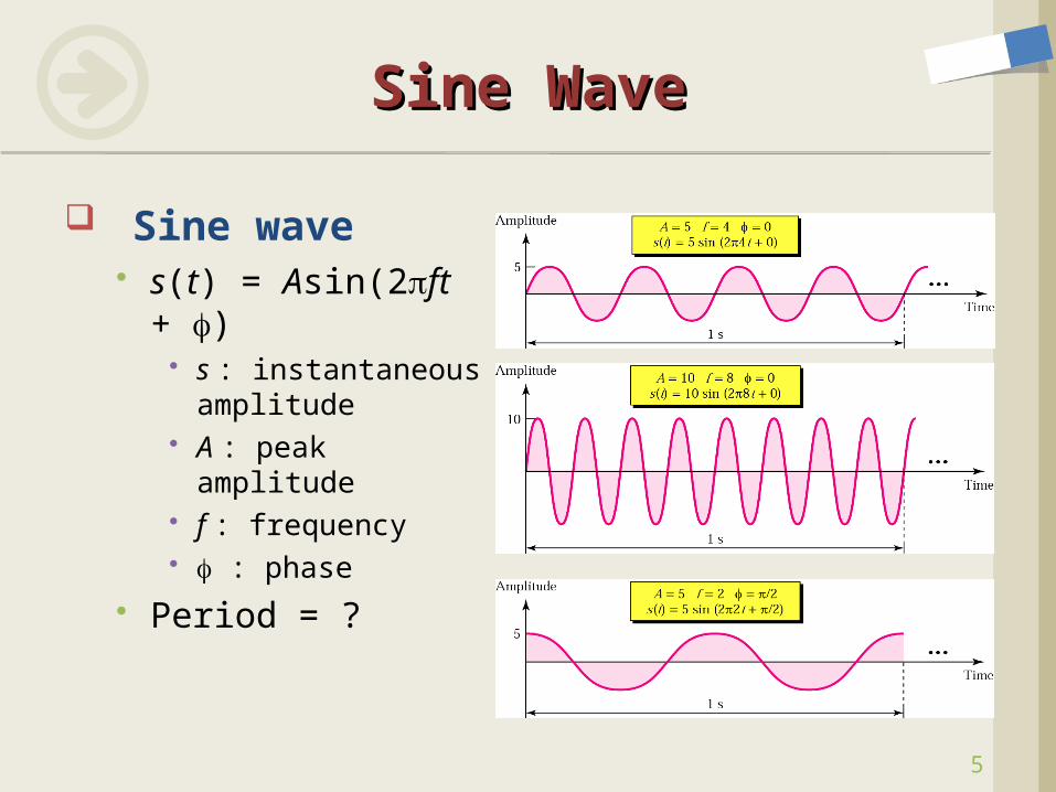
Sine wave s(t) = Asin(2ft +
) s : instantaneous
amplitude A : peak amplitude f : frequency : phase
Period = ?
6
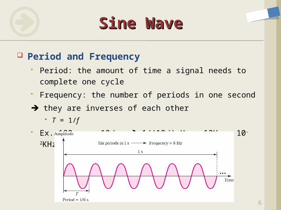
Period and Frequency Period: the amount of time a signal needs to complete
one cycle
Frequency: the number of periods in one second
they are inverses of each other T = 1/f
Ex. 100 ms = 10-1 s 1/(10-1) Hz = 10Hz = 10-2KHz
Sine WaveSine Wave
7
More about Frequency Frequency: the rate of change wrt. time.
Change in a short span of time high frequency Change over a long span of time low frequency
Two Extremes A signal does not change at all frequency = 0 (DC) A signal changes instantaneously frequency = infinite
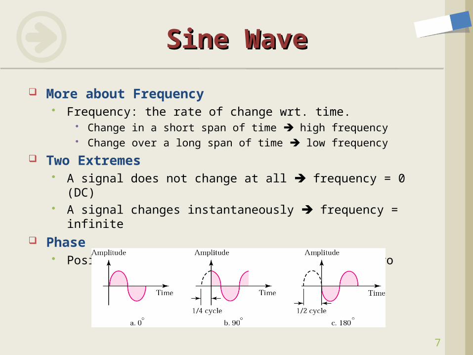
Phase Position of the waveform relative to time zero
Sine WaveSine Wave
8
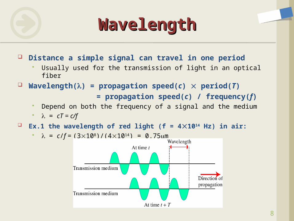
Distance a simple signal can travel in one period Usually used for the transmission of light in an optical fiber
Wavelength() = propagation speed(c) period(T) = propagation speed(c) / frequency(f)
Depend on both the frequency of a signal and the medium = cT = c/f
Ex.1 the wavelength of red light (f = 41014 Hz) in air: = c/f = (3108)/(41014) = 0.75m
WavelengthWavelength
9
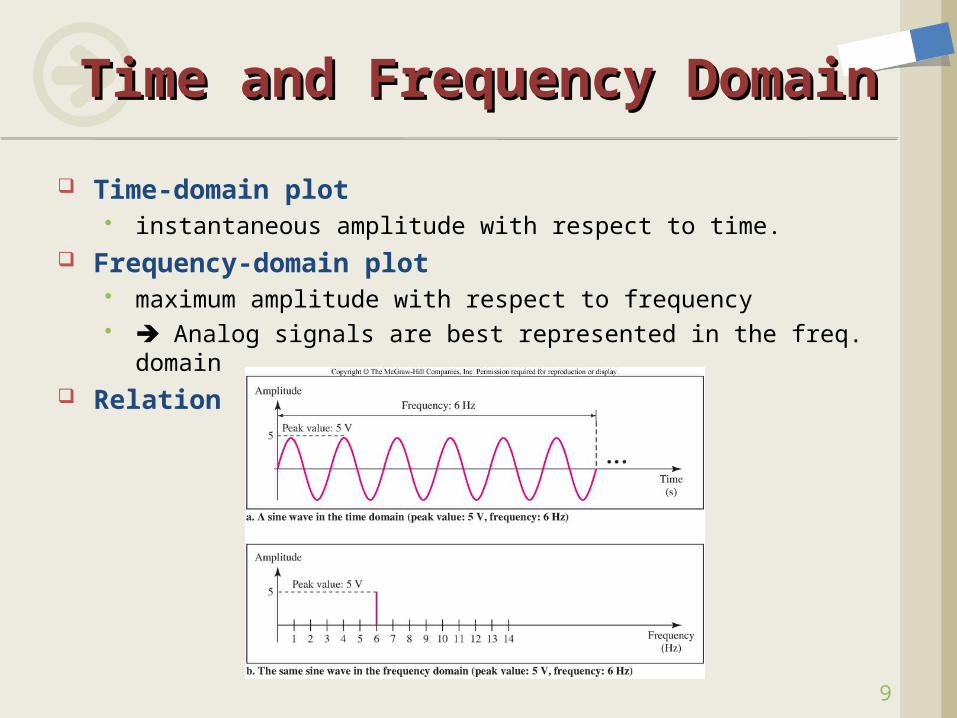
Time-domain plot instantaneous amplitude with respect to time.
Frequency-domain plot maximum amplitude with respect to frequency Analog signals are best represented in the freq. domain
Relation
Time and Frequency Time and Frequency DomainDomain
10
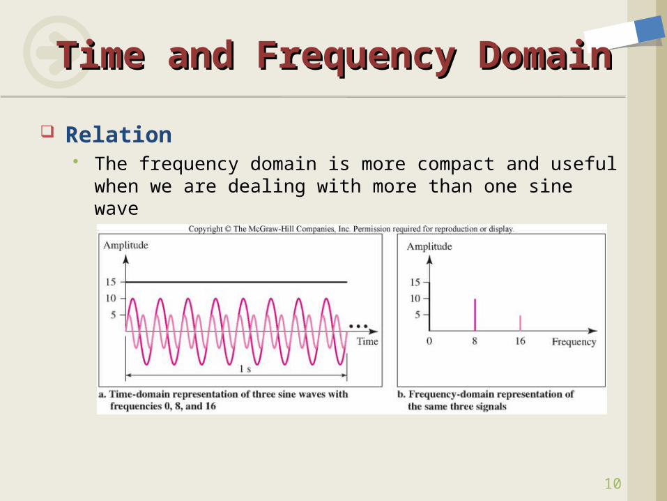
Relation The frequency domain is more compact and useful
when we are dealing with more than one sine wave
Time and Frequency Time and Frequency DomainDomain
11
Usage of a single sine wave Carry of electric energy (power) single tone not useful in data communications to make signals that can carry information, we
have to add several different sine waves (composite signals)
Composite Signals A periodic signal decomposed into two or more
sine waves. Fourier Analysis (Transform) is used to decompose
a composite signal into its components
Composite SignalsComposite Signals
12
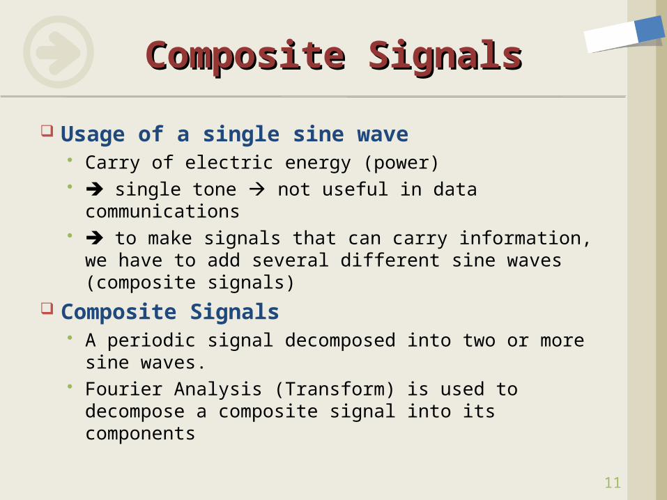
Fourier Analysis Any composite signal can be represented as a
combination of simple sine waves with different frequencies, phases, and amplitudes
An example: a square wave
Composite SignalsComposite Signals
13
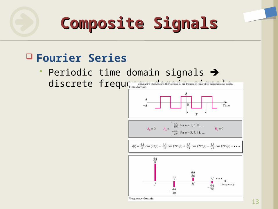
Fourier Series Periodic time domain signals discrete
frequency domain signals
Composite SignalsComposite Signals
14
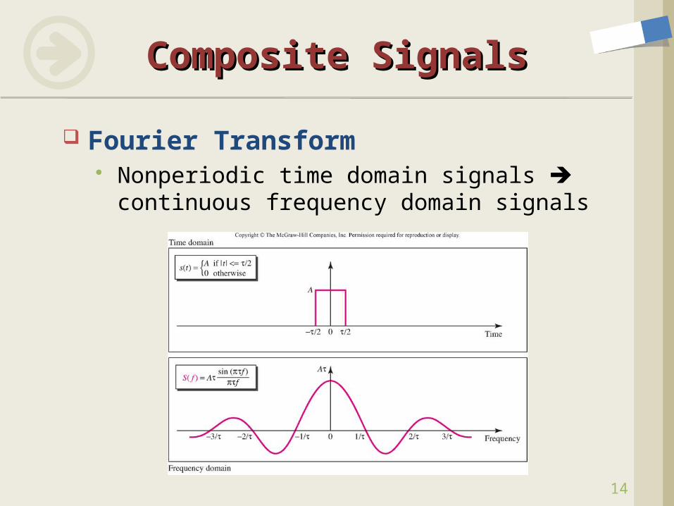
Fourier Transform Nonperiodic time domain signals
continuous frequency domain signals
Composite SignalsComposite Signals
15
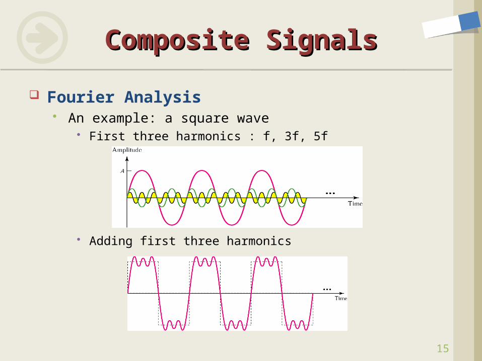
Fourier Analysis An example: a square wave
First three harmonics : f, 3f, 5f
Adding first three harmonics
Composite SignalsComposite Signals
16
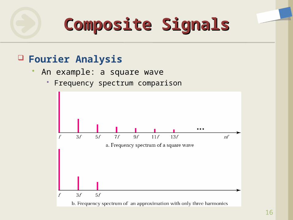
Fourier Analysis An example: a square wave
Frequency spectrum comparison
Composite SignalsComposite Signals
17
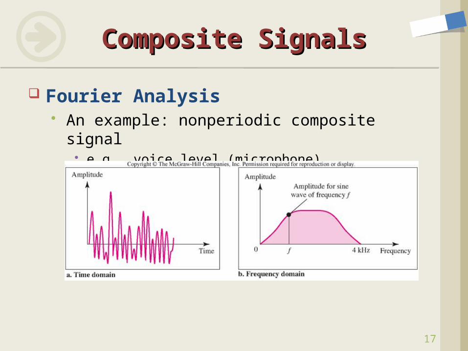
Fourier Analysis An example: nonperiodic composite signal
e.g., voice level (microphone)
Composite SignalsComposite Signals
18
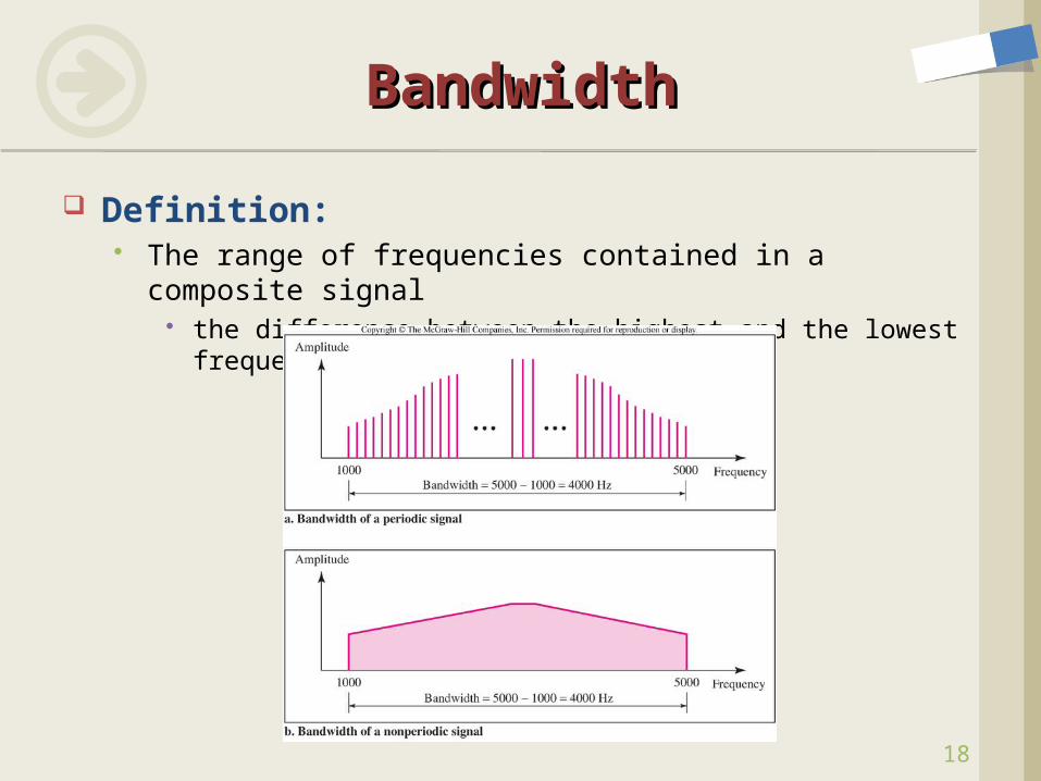
Definition: The range of frequencies contained in a composite
signal the difference between the highest and the lowest
frequencies
BandwidthBandwidth
19
Example: Which signal has a wider bandwidth, a
sine wave with a frequency of 100Hz or a sine wave with a frequency of 200Hz?
BandwidthBandwidth
20
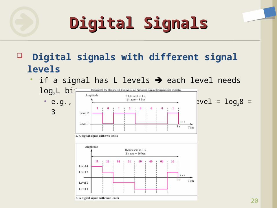
Digital signals with different signal levels if a signal has L levels each level needs log2L bits
e.g., 8 levels no. of bits per level = log28 = 3
Digital SignalsDigital Signals
21
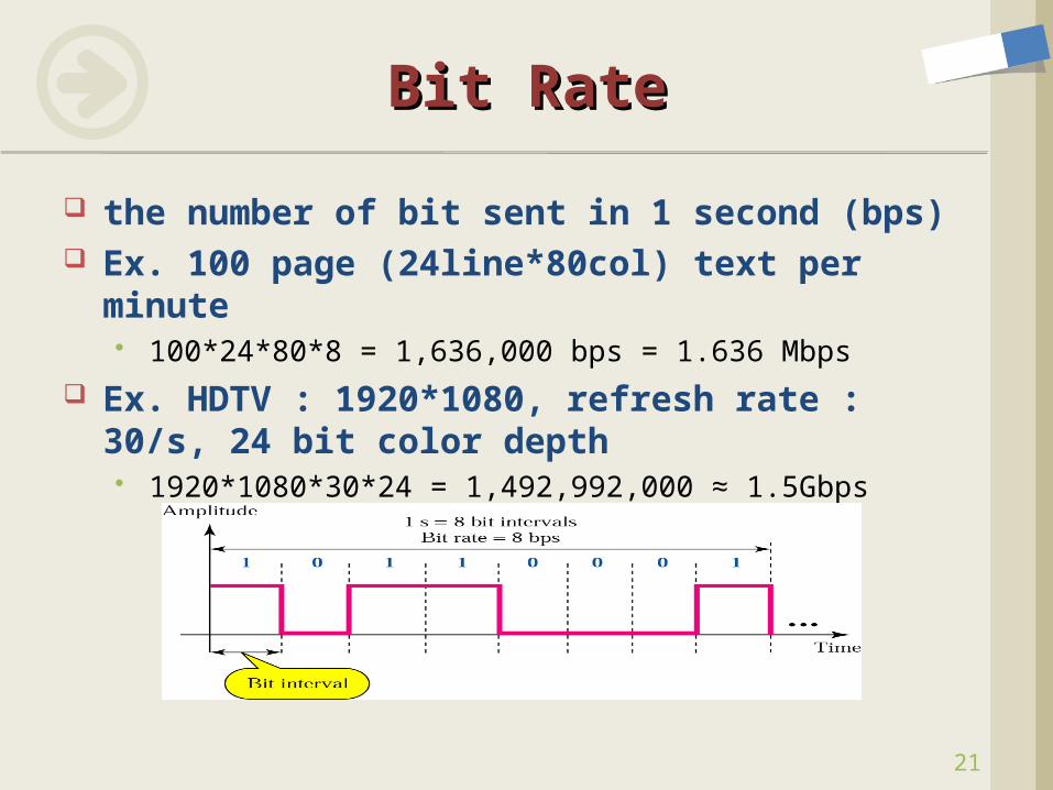
the number of bit sent in 1 second (bps) Ex. 100 page (24line*80col) text per minute
100*24*80*8 = 1,636,000 bps = 1.636 Mbps Ex. HDTV : 1920*1080, refresh rate : 30/s,
24 bit color depth 1920*1080*30*24 = 1,492,992,000 ≈ 1.5Gbps
Bit RateBit Rate
22
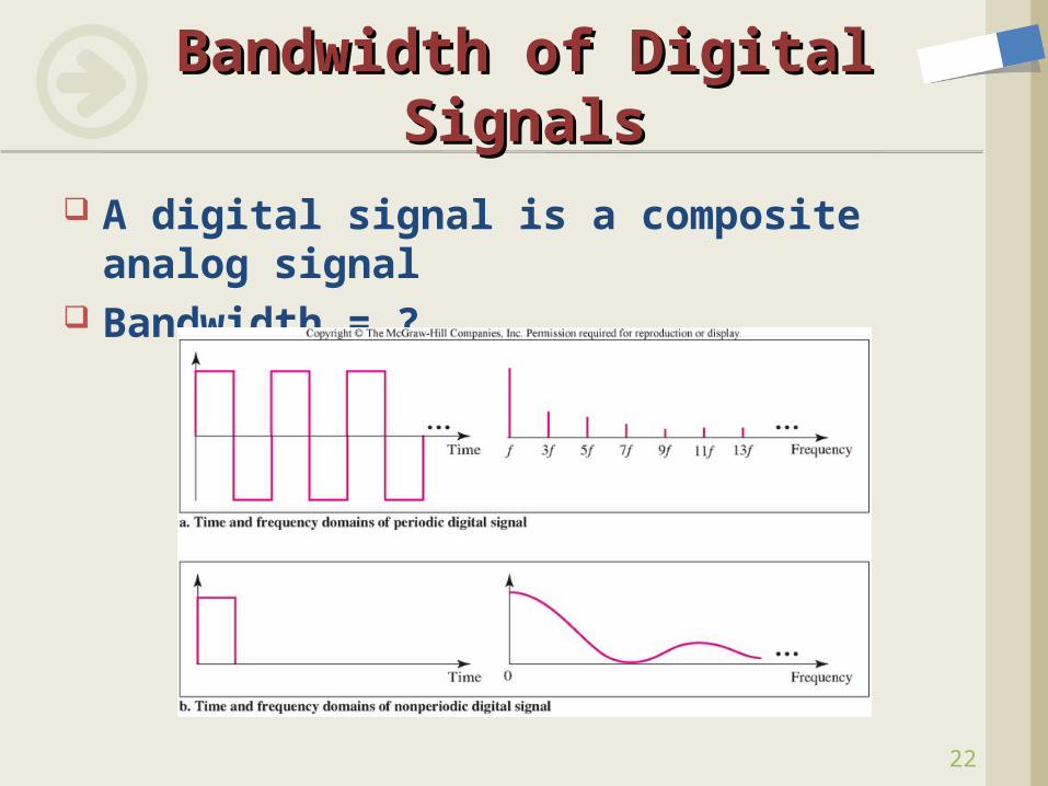
A digital signal is a composite analog signal
Bandwidth = ?
Bandwidth of Digital Bandwidth of Digital SignalsSignals
23
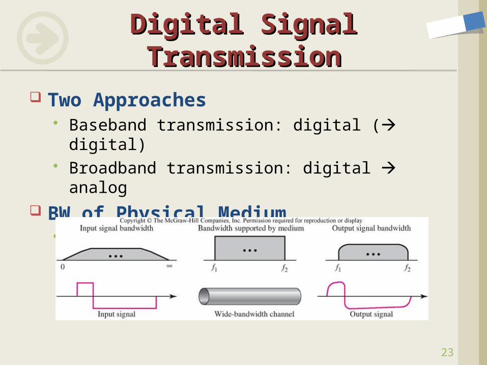
Two Approaches Baseband transmission: digital ( digital) Broadband transmission: digital analog
BW of Physical Medium The frequency BW that medium can pass
Digital Signal TransmissionDigital Signal Transmission
24
The required BW for the given bit rate Nyquist theorem (Noiseless assumption)
Bit Rate (n) 2BW log2L (L = # of signal levels) Why?
Ex.1 Consider the same noiseless channel, transmitting a signal with four signal levels. The maximum bit rate is:
BitRate = 2 3000 log24 = 12,000bps
Ex.2 We need to send 256 kbps over a noiseless channel with a BW of 20kHz. how many signal levels do we need?
256,000 = 2 20,000 log2L
log2L = 6.625, L = 26.625 = 98.7 levels 128 levels
Bit Rate and BW Bit Rate and BW
25
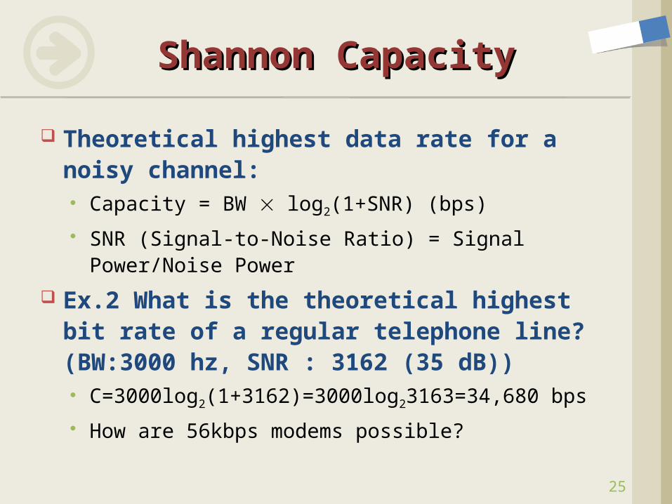
Theoretical highest data rate for a noisy channel: Capacity = BW log2(1+SNR) (bps)
SNR (Signal-to-Noise Ratio) = Signal Power/Noise Power
Ex.2 What is the theoretical highest bit rate of a regular telephone line? (BW:3000 hz, SNR : 3162 (35 dB)) C=3000log2(1+3162)=3000log23163=34,680 bps
How are 56kbps modems possible?
Shannon CapacityShannon Capacity
26
Using Both LimitsUsing Both Limits
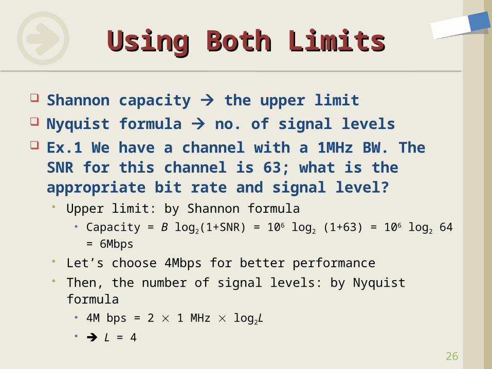
Shannon capacity the upper limit Nyquist formula no. of signal levels Ex.1 We have a channel with a 1MHz BW.
The SNR for this channel is 63; what is the appropriate bit rate and signal level? Upper limit: by Shannon formula
Capacity = B log2(1+SNR) = 106 log2 (1+63) = 106 log2 64
= 6Mbps
Let’s choose 4Mbps for better performance Then, the number of signal levels: by Nyquist formula
4M bps = 2 1 MHz log2L
L = 4
27
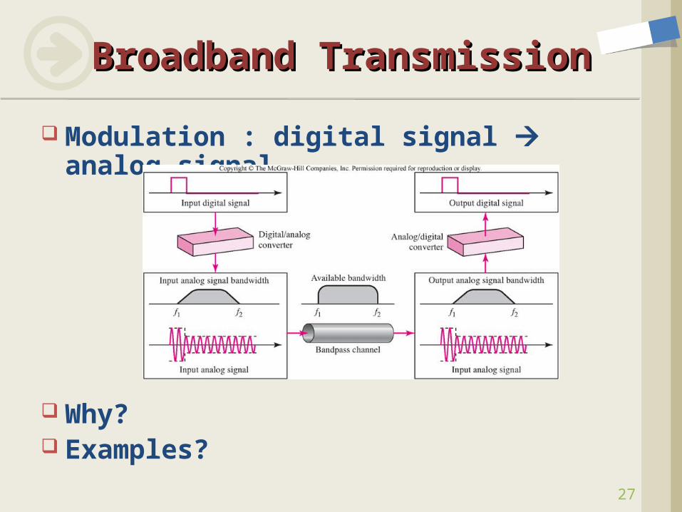
Modulation : digital signal analog signal
Why? Examples?
Broadband TransmissionBroadband Transmission
28
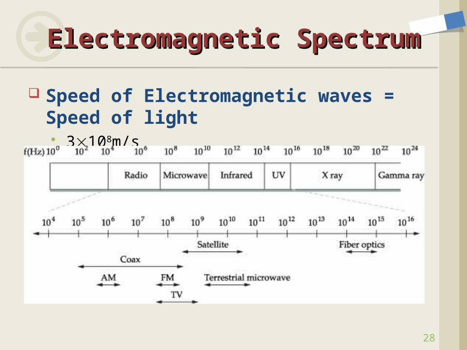
Speed of Electromagnetic waves = Speed of light 3108m/s
Electromagnetic SpectrumElectromagnetic Spectrum
29
Signals Hardware Building Blocks
Nodes Links
Encoding Framing Error Detection Reliable Transmission Project #1 Ethernet Wireless Assignment #2
ContentsContents
30
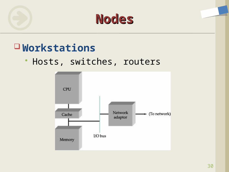
Workstations Hosts, switches, routers
NodesNodes
31
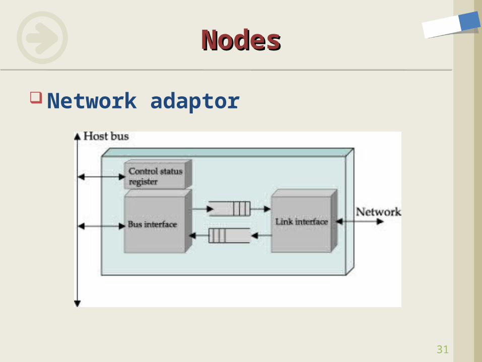
Network adaptor
NodesNodes
32
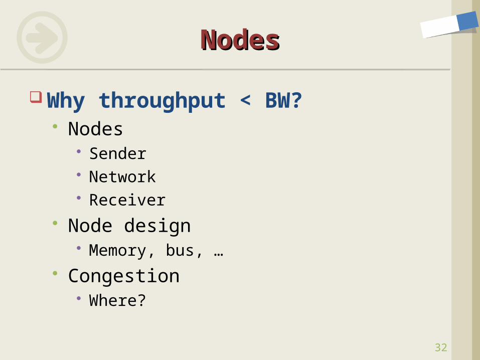
Why throughput < BW? Nodes
Sender Network Receiver
Node design Memory, bus, …
Congestion Where?
NodesNodes
33
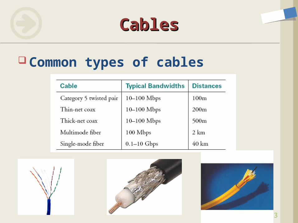
Common types of cables
CablesCables
34
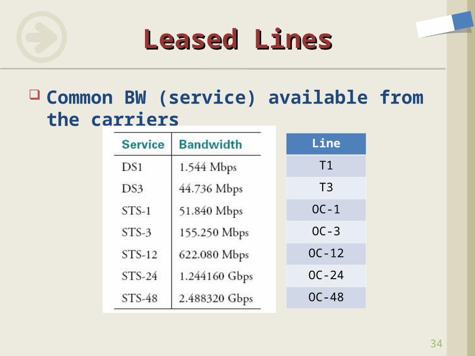
Common BW (service) available from the carriers
Leased LinesLeased Lines
Line
T1
T3
OC-1
OC-3
OC-12
OC-24
OC-48
35
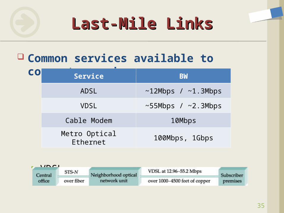
Common services available to connect your home
VDSL
Last-Mile LinksLast-Mile Links
Service BW
ADSL ~12Mbps / ~1.3Mbps
VDSL ~55Mbps / ~2.3Mbps
Cable Modem 10Mbps
Metro Optical Ethernet 100Mbps, 1Gbps
36
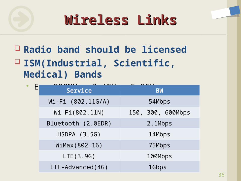
Radio band should be licensed ISM(Industrial, Scientific, Medical)
Bands Ex. 900MHs, 2.4GHz, 5.8GHz
Wireless LinksWireless Links
Service BW
Wi-Fi (802.11G/A) 54Mbps
Wi-Fi(802.11N) 150, 300, 600Mbps
Bluetooth (2.0EDR) 2.1Mbps
HSDPA (3.5G) 14Mbps
WiMax(802.16) 75Mbps
LTE(3.9G) 100Mbps
LTE-Advanced(4G) 1Gbps
37
Signals Hardware Building Blocks Encoding
NRZI, RZ, Manchester, Block coding Decoding Problems
Framing Error Detection Reliable Transmission Project #1 Ethernet Wireless Assignment #2
ContentsContents
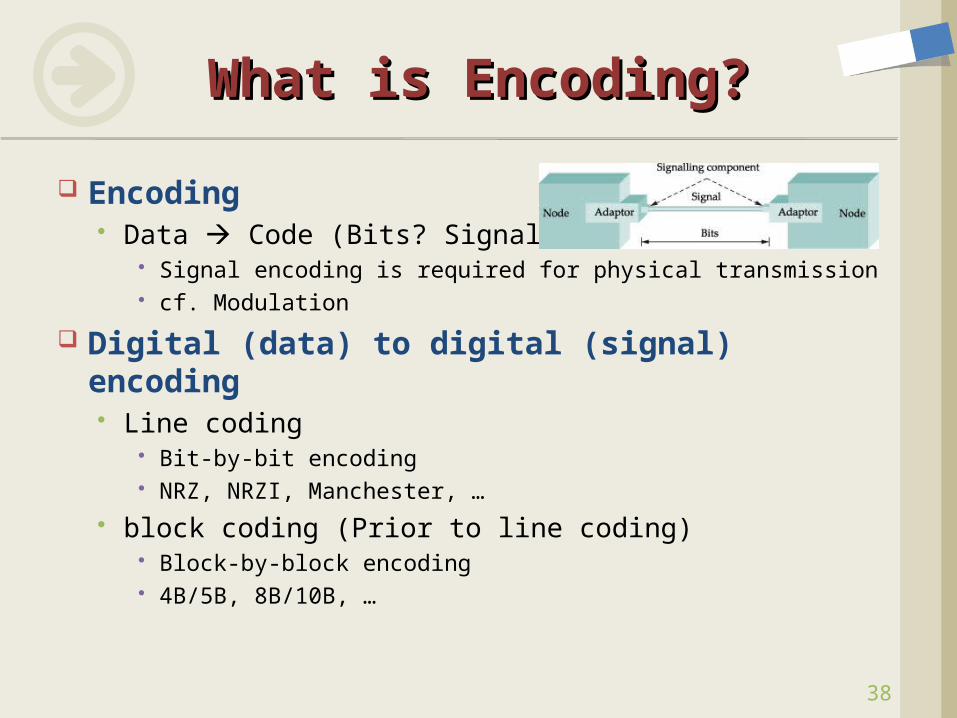
Encoding Data Code (Bits? Signals?)
Signal encoding is required for physical transmission cf. Modulation
Digital (data) to digital (signal) encoding Line coding
Bit-by-bit encoding NRZ, NRZI, Manchester, …
block coding (Prior to line coding) Block-by-block encoding 4B/5B, 8B/10B, …
What is Encoding?What is Encoding?
38
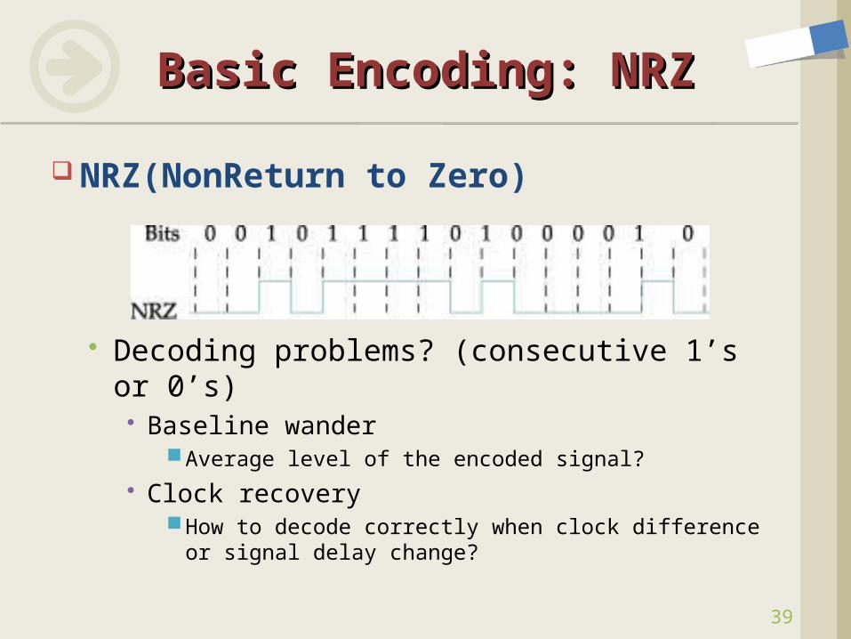
NRZ(NonReturn to Zero)
Decoding problems? (consecutive 1’s or 0’s)
Baseline wander Average level of the encoded signal?
Clock recoveryHow to decode correctly when clock difference or
signal delay change?
Basic Encoding: NRZBasic Encoding: NRZ
39
Baseline Wander How to make average = 0?
Clock Recovery Separate clock transmission?
Encoding Design Problem No Baseline Wander Self Clock Recovery Signal BW , bit rate Reliability (special features)
How to Solve Decoding How to Solve Decoding Problems?Problems?
40
41
Bit Rates and Baud RatesBit Rates and Baud Rates
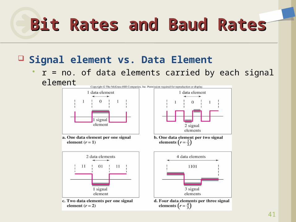
Signal element vs. Data Element r = no. of data elements carried by each signal element
42
Bit Rates and Baud RatesBit Rates and Baud Rates
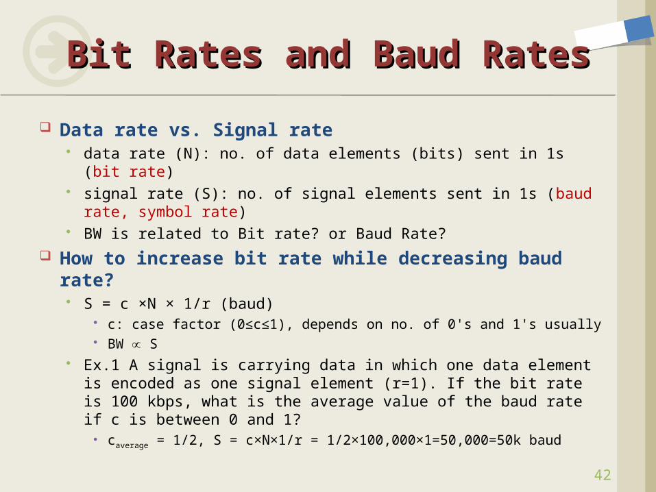
Data rate vs. Signal rate data rate (N): no. of data elements (bits) sent in 1s (bit rate) signal rate (S): no. of signal elements sent in 1s (baud rate,
symbol rate) BW is related to Bit rate? or Baud Rate?
How to increase bit rate while decreasing baud rate? S = c ×N × 1/r (baud)
c: case factor (0≤c≤1), depends on no. of 0's and 1's usually BW S
Ex.1 A signal is carrying data in which one data element is encoded as one signal element (r=1). If the bit rate is 100 kbps, what is the average value of the baud rate if c is between 0 and 1?
caverage = 1/2, S = c×N×1/r = 1/2×100,000×1=50,000=50k baud
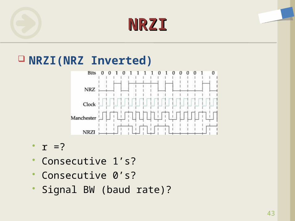
NRZI(NRZ Inverted)
r =? Consecutive 1’s? Consecutive 0’s? Signal BW (baud rate)?
NRZINRZI
43
44
RZRZ
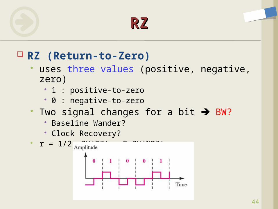
RZ (Return-to-Zero) uses three values (positive, negative, zero)
1 : positive-to-zero 0 : negative-to-zero
Two signal changes for a bit BW? Baseline Wander? Clock Recovery?
r = 1/2, BW(RZ) = 2 BW(NRZ)
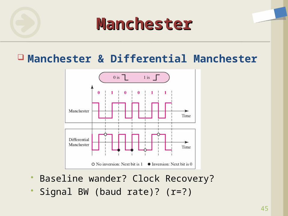
Manchester & Differential Manchester
Baseline wander? Clock Recovery? Signal BW (baud rate)? (r=?)
ManchesterManchester
45
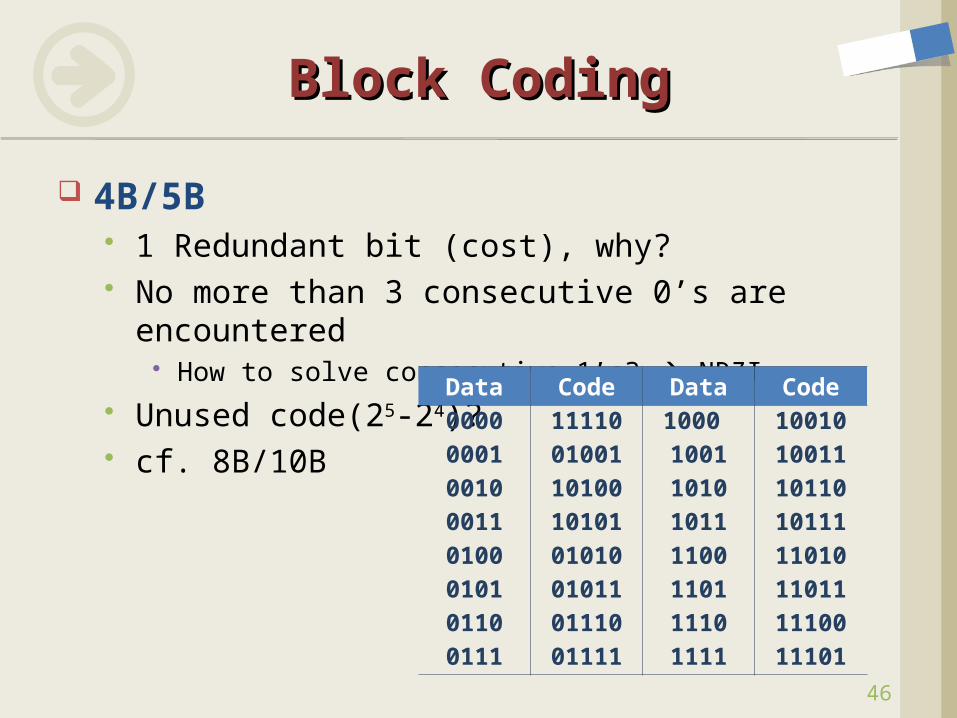
4B/5B 1 Redundant bit (cost), why? No more than 3 consecutive 0’s are
encountered How to solve consecutive 1’s? NRZI
Unused code(25-24)? cf. 8B/10B
Block CodingBlock Coding
46
Data Code Data Code0000 11110 1000 100100001 01001 1001 100110010 10100 1010 101100011 10101 1011 101110100 01010 1100 110100101 01011 1101 110110110 01110 1110 111000111 01111 1111 11101
47
Signals Hardware Building Blocks Encoding Framing
Byte-Oriented vs. Bit-Oriented Framing Approaches
Error Detection Reliable Transmission Project #1 Ethernet Wireless Assignment #2
ContentsContents
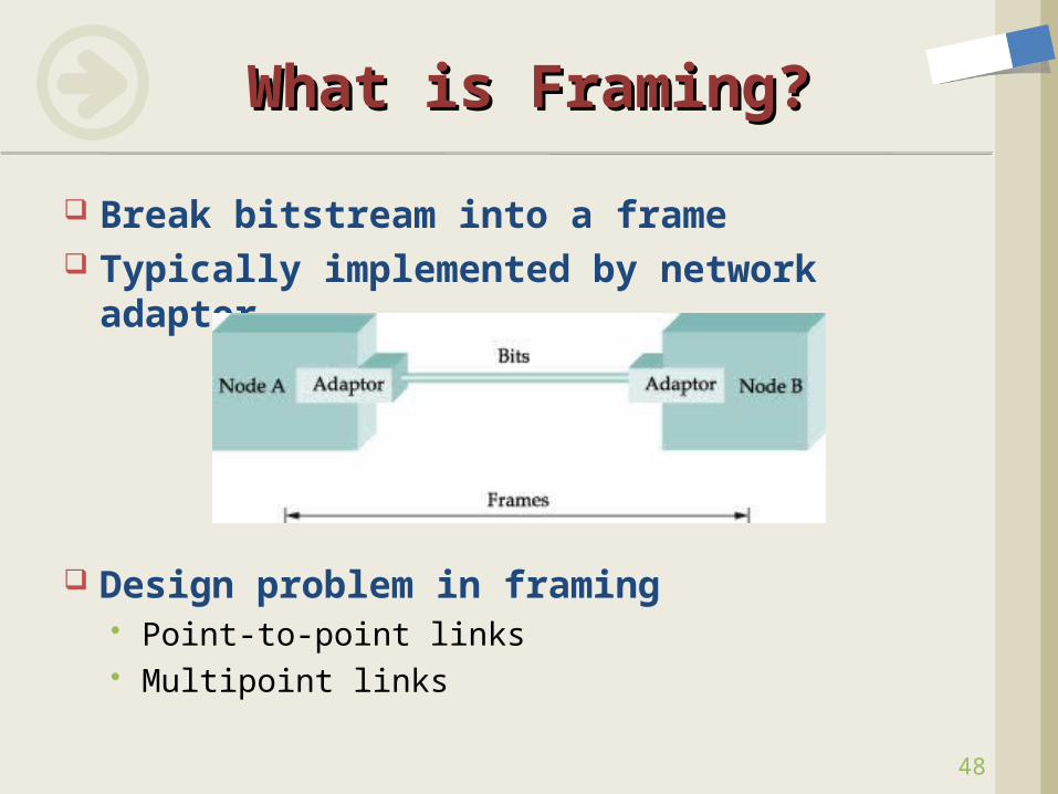
Break bitstream into a frame Typically implemented by network
adaptor
Design problem in framing Point-to-point links Multipoint links
What is Framing?What is Framing?
48
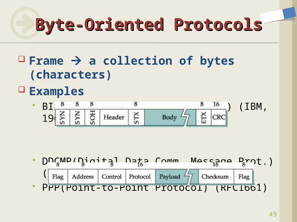
Frame a collection of bytes (characters)
Examples BISYNC(Binary Synchronous Comm.) (IBM,
1967)
DDCMP(Digital Data Comm. Message Prot.)(DECNET)
PPP(Point-to-Point Protocol) (RFC1661)
Byte-Oriented ProtocolsByte-Oriented Protocols
49
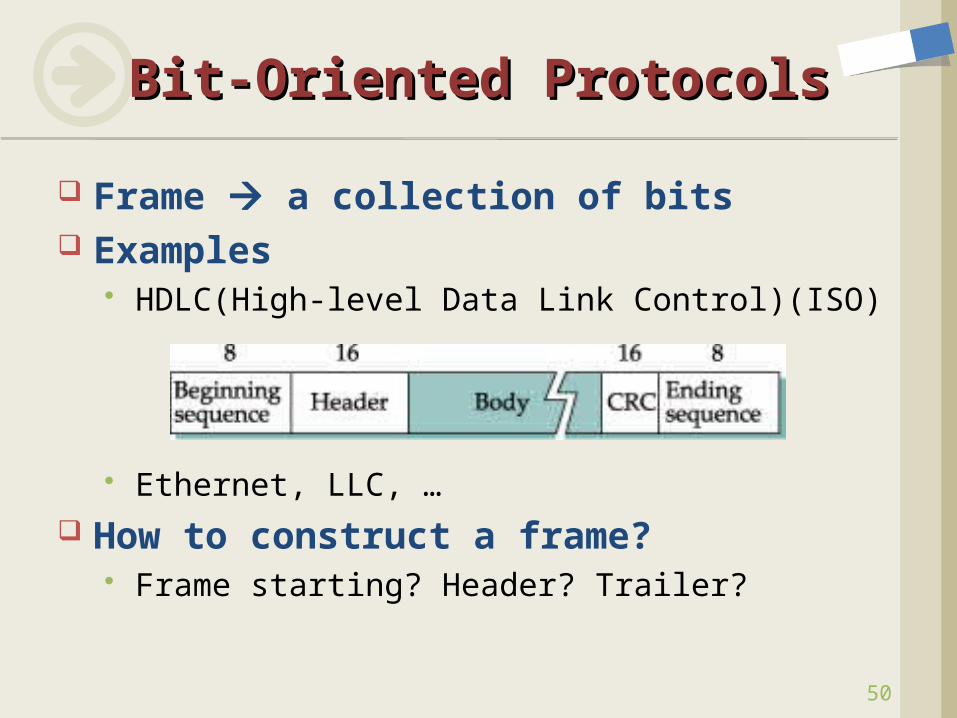
Frame a collection of bits Examples
HDLC(High-level Data Link Control)(ISO)
Ethernet, LLC, … How to construct a frame?
Frame starting? Header? Trailer?
Bit-Oriented ProtocolsBit-Oriented Protocols
50
Sentinel-based Delineate frame with special character or
pattern BISYNC, DDCMP: SYN character PPP, HDLC: Flag(01111110)
Problem: special char. or pattern appears in the payload
Charater stuffing (Byte-Oriented Protocols) Extra characters are inserted (ESC character)
Bit stuffing (Bit-Oriented Protocols) Sender: insert 0 after five consecutive 1’s (why?) Receiver: delete 0 that follows five consecutive 1’s
Framing ApproachesFraming Approaches
51
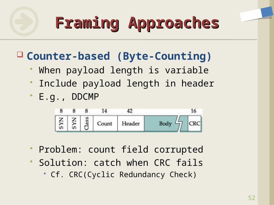
Counter-based (Byte-Counting) When payload length is variable Include payload length in header E.g., DDCMP
Problem: count field corrupted Solution: catch when CRC fails
Cf. CRC(Cyclic Redundancy Check)
Framing ApproachesFraming Approaches
52
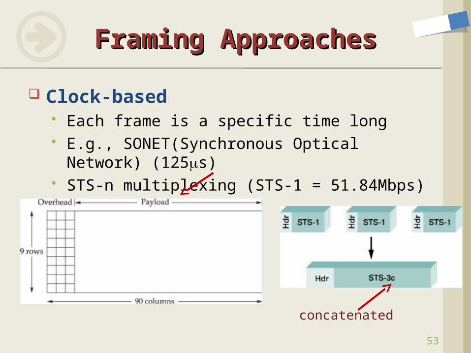
Clock-based Each frame is a specific time long E.g., SONET(Synchronous Optical Network)
(125s) STS-n multiplexing (STS-1 = 51.84Mbps)
Framing ApproachesFraming Approaches
53
concatenated
54
Signals Hardware Building Blocks Encoding Framing Error Detection
Error Detection and Error Correction 2D parity, Checksum, CRC
Reliable Transmission Project #1 Ethernet Wireless Assignment #2
ContentsContents
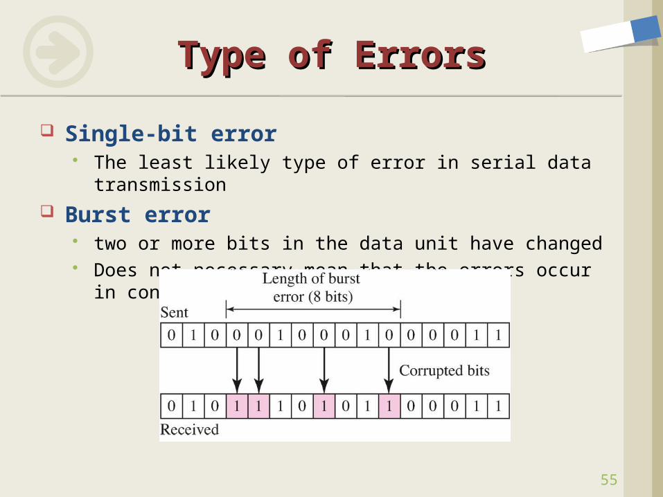
Single-bit error The least likely type of error in serial data transmission
Burst error two or more bits in the data unit have changed Does not necessary mean that the errors occur in
consecutive bits
Type of ErrorsType of Errors
55
56
Detection Vs. CorrectionDetection Vs. Correction
Redundancy Adding extra bits and Sending
Error Detection Has any error occurred?
Yes, or No
Error Correction the number of bits corrupted the location of corrupted bits ex. the number of bits: 10 bits, 1000 bit message
# of possibility: 1000C10 = 1000×999×…×991/(10×9×…×1)=?
Error correcting code (FEC) vs. Retransmission
57
Error Detecting CodeError Detecting Code
How do we create redundant bits? Cost? Performance?
Parity Check One bit is added (even-parity bit, odd-parity
bit) Performance?
Two-Dimensional Parity CRC (Cyclic Redundancy Check) Checksum
58
Modular ArithmeticModular Arithmetic
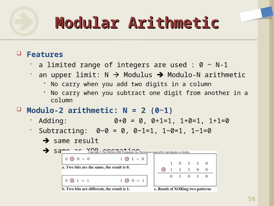
Features a limited range of integers are used : 0 ~ N-1 an upper limit: N Modulus Modulo-N arithmetic
No carry when you add two digits in a column No carry when you subtract one digit from another in a column
Modulo-2 arithmetic: N = 2 (0~1) Adding: 0+0 = 0, 0+1=1, 1+0=1, 1+1=0 Subtracting: 0−0 = 0, 0−1=1, 1−0=1, 1−1=0 same result same as XOR operation
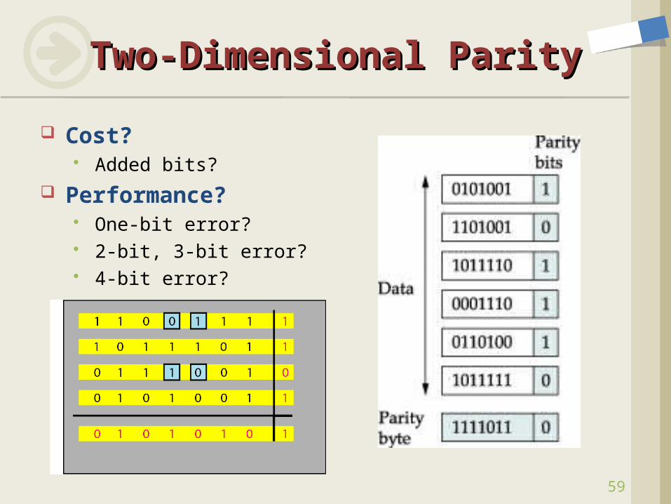
Cost? Added bits?
Performance? One-bit error? 2-bit, 3-bit error? 4-bit error?
Two-Dimensional ParityTwo-Dimensional Parity
59
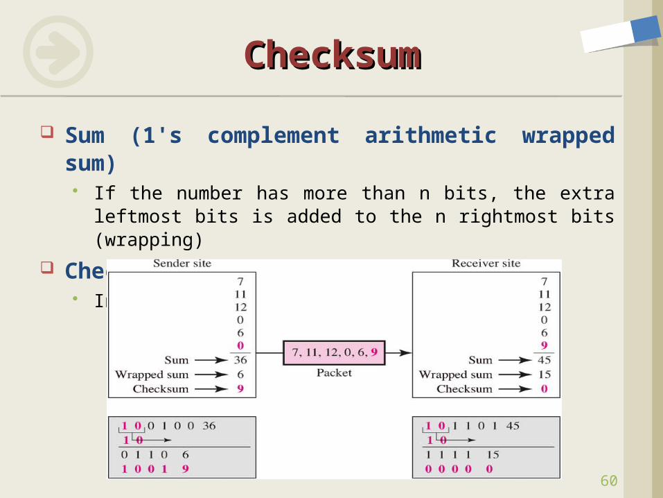
Sum (1's complement arithmetic wrapped sum) If the number has more than n bits, the extra leftmost
bits is added to the n rightmost bits (wrapping)
Checksum Inverting all bits of sum (negative value)
ChecksumChecksum
60
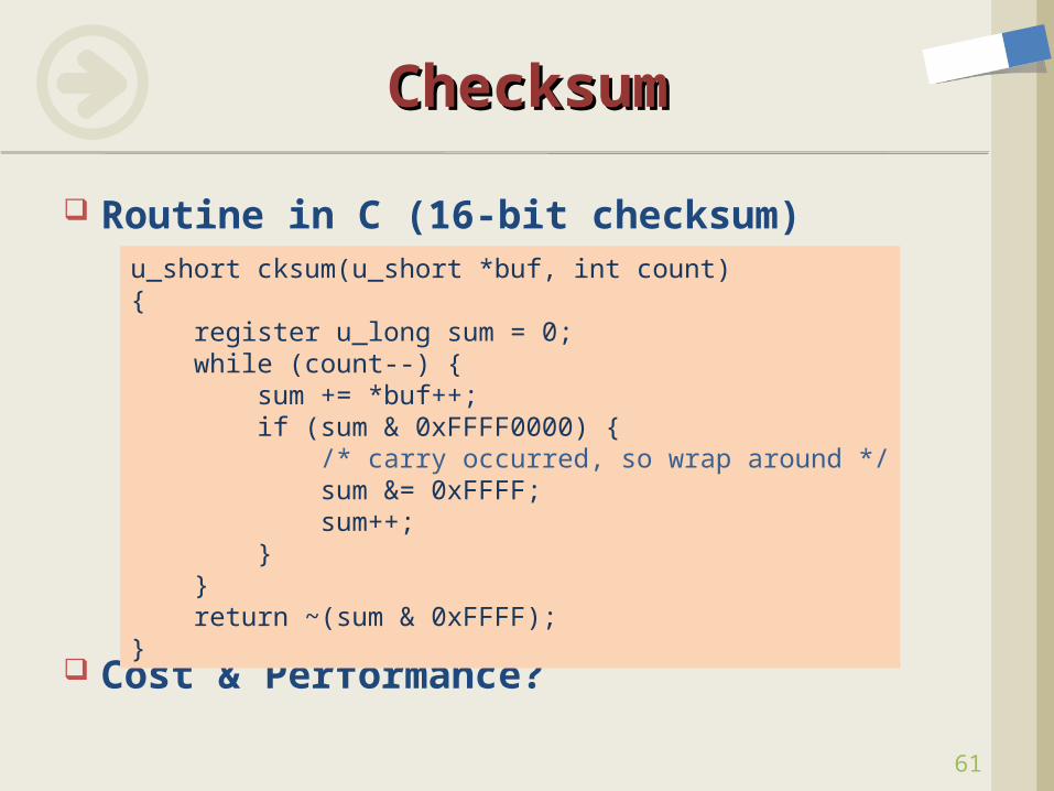
Routine in C (16-bit checksum)
Cost & Performance?
ChecksumChecksum
61
u_short cksum(u_short *buf, int count){ register u_long sum = 0; while (count--) { sum += *buf++; if (sum & 0xFFFF0000) { /* carry occurred, so wrap around */ sum &= 0xFFFF; sum++; } } return ~(sum & 0xFFFF);}
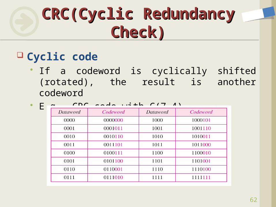
Cyclic code If a codeword is cyclically shifted (rotated), the
result is another codeword E.g., CRC code with C(7,4)
CRC(Cyclic Redundancy CRC(Cyclic Redundancy Check)Check)
62
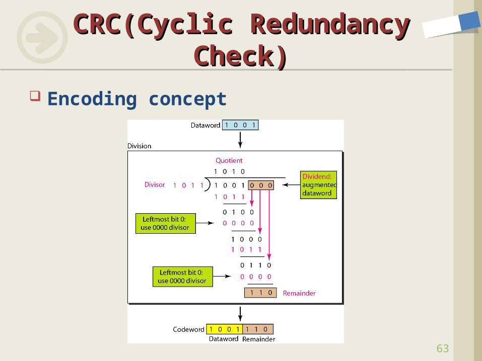
Encoding concept
CRC(Cyclic Redundancy CRC(Cyclic Redundancy Check)Check)
63
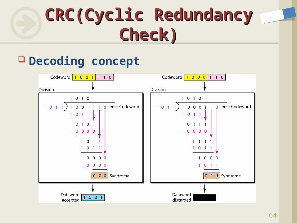
Decoding concept
CRC(Cyclic Redundancy CRC(Cyclic Redundancy Check)Check)
64
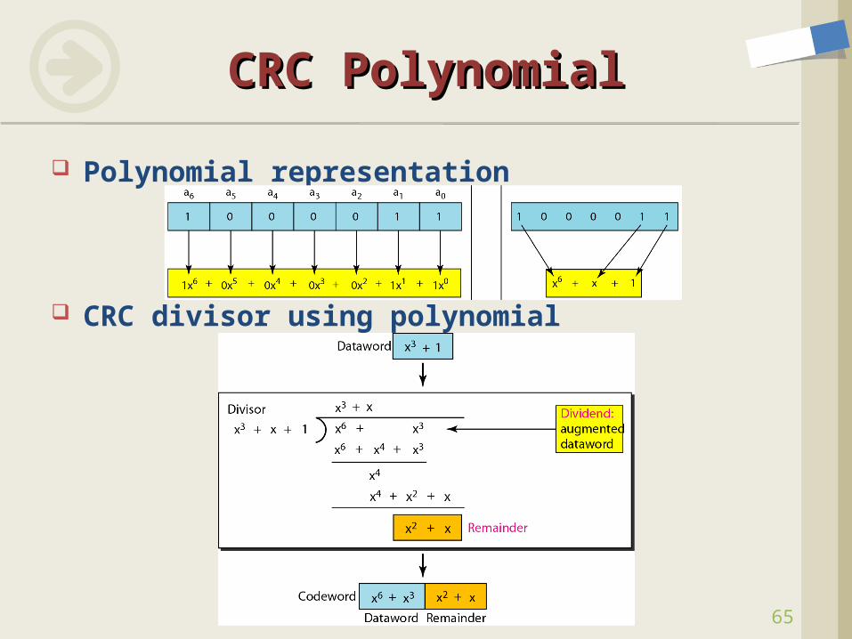
Polynomial representation
CRC divisor using polynomial
CRC PolynomialCRC Polynomial
65
66
CRC PerformanceCRC Performance
Some definitions Message: M(x) Transmitted Message: P(x) Divisor: C(x) Error: E(x)
In a cyclic code: If P(x)/C(x) ≠ 0, one or more bits is corrupted If P(x)/C(x) = 0, either
No bit is corrupted, or Some bits are corrupted, but the decoder failed to detect them
Received codeword = P(x) + E(x) Received codeword/g(x) = P(x)/C(x) + E(x)/C(x) E(x) errors that are divisible by C(x) are not caught
67
CRC PerformanceCRC Performance
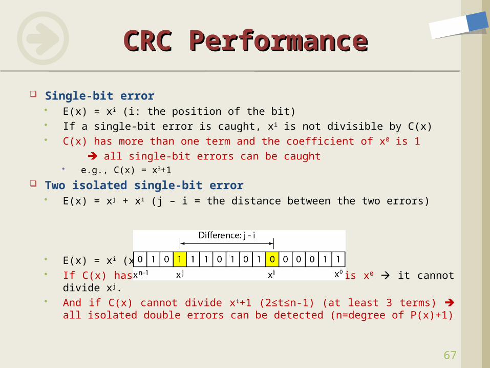
Single-bit error E(x) = xi (i: the position of the bit) If a single-bit error is caught, xi is not divisible by C(x) C(x) has more than one term and the coefficient of x0 is 1 all single-bit errors can be caught
e.g., C(x) = x3+1
Two isolated single-bit error E(x) = xj + xi (j – i = the distance between the two errors)
E(x) = xi (xj-i + 1), j-i>1, i≥0 If C(x) has more than one term and one term is x0 it cannot divide
xj. And if C(x) cannot divide xt+1 (2≤t≤n-1) (at least 3 terms) all
isolated double errors can be detected (n=degree of P(x)+1)
68
CRC PerformanceCRC Performance
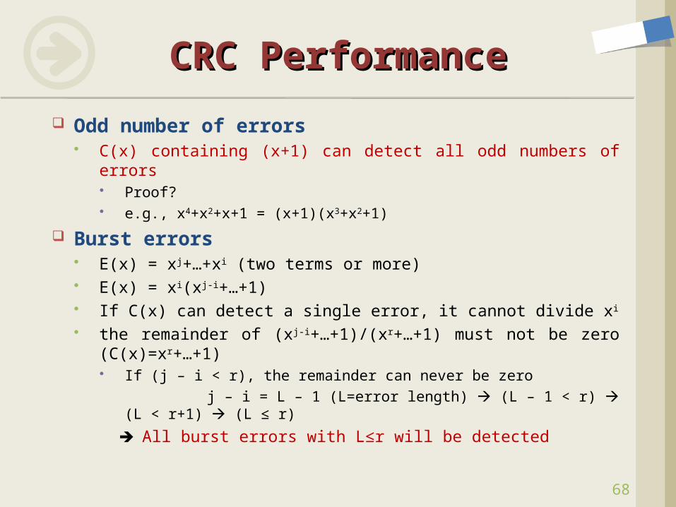
Odd number of errors C(x) containing (x+1) can detect all odd numbers of errors
Proof? e.g., x4+x2+x+1 = (x+1)(x3+x2+1)
Burst errors E(x) = xj+…+xi (two terms or more) E(x) = xi(xj-i+…+1) If C(x) can detect a single error, it cannot divide xi
the remainder of (xj-i+…+1)/(xr+…+1) must not be zero (C(x)=xr+…+1) If (j – i < r), the remainder can never be zero j – i = L – 1 (L=error length) (L – 1 < r) (L < r+1)
(L ≤ r)
All burst errors with L≤r will be detected
69
CRC Summary (1)CRC Summary (1)
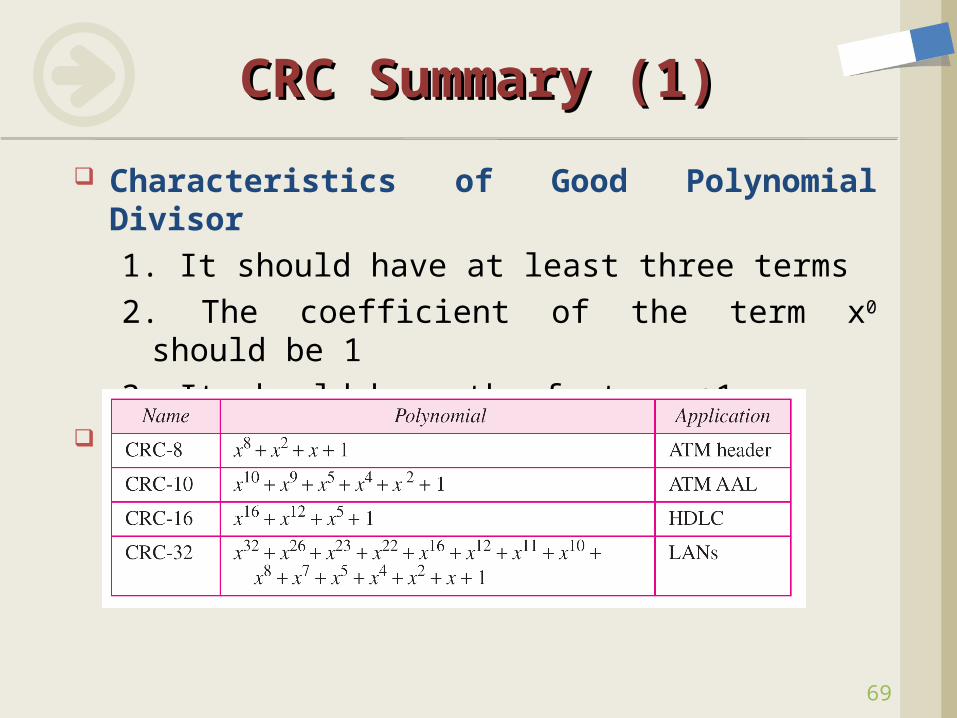
Characteristics of Good Polynomial Divisor1. It should have at least three terms2. The coefficient of the term x0 should be 13. It should have the factor x+1
Standard Polynomials
70
CRC Summary (2)CRC Summary (2)
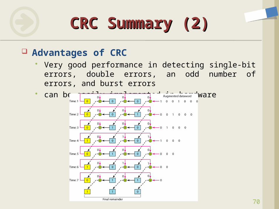
Advantages of CRC Very good performance in detecting single-bit errors,
double errors, an odd number of errors, and burst errors
can be easily implemented in hardware
71
Signals Hardware Building Blocks Encoding Framing Error Detection Reliable Transmission
Stop-and Wait Sliding Windows Go-Back-N, Selective Repeat
Project #1 Ethernet Wireless Assignment #2
ContentsContents
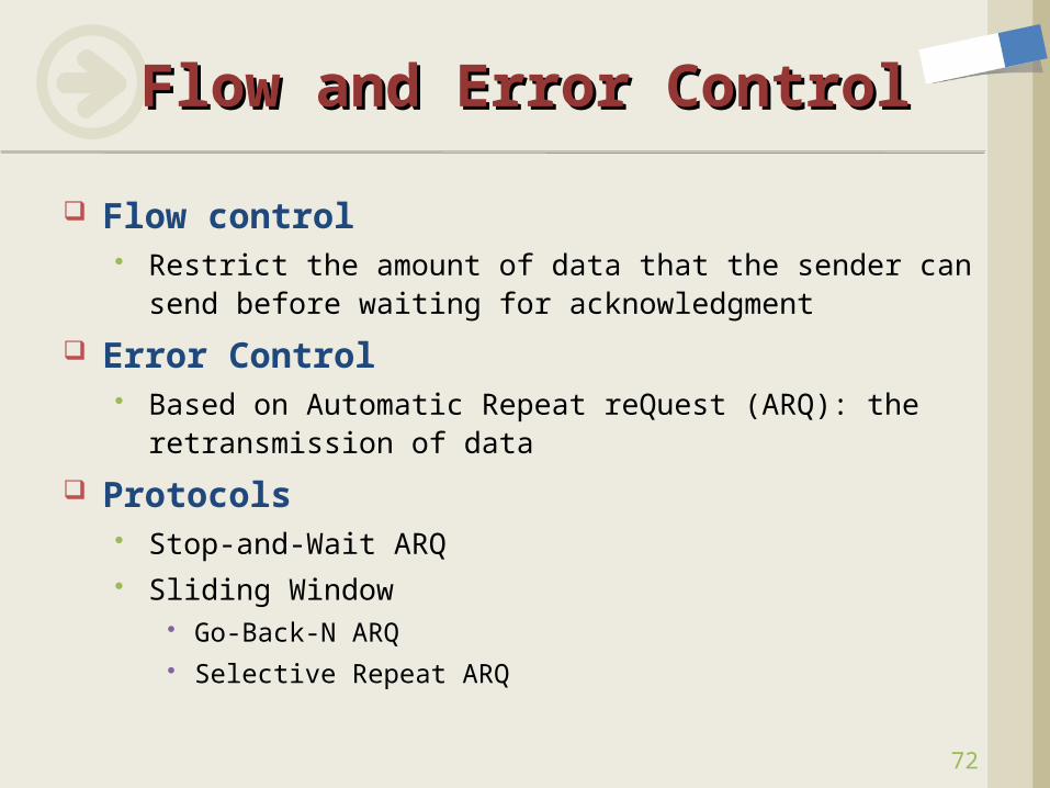
Flow control Restrict the amount of data that the sender can send
before waiting for acknowledgment
Error Control Based on Automatic Repeat reQuest (ARQ): the
retransmission of data
Protocols Stop-and-Wait ARQ Sliding Window
Go-Back-N ARQ Selective Repeat ARQ
Flow and Error ControlFlow and Error Control
72
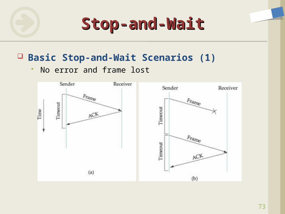
Basic Stop-and-Wait Scenarios (1) No error and frame lost
Stop-and-WaitStop-and-Wait
73
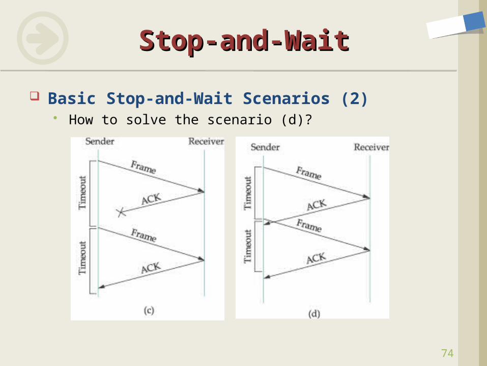
Basic Stop-and-Wait Scenarios (2) How to solve the scenario (d)?
Stop-and-WaitStop-and-Wait
74
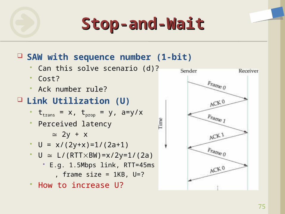
SAW with sequence number (1-bit) Can this solve scenario (d)? Cost? Ack number rule?
Link Utilization (U) ttrans = x, tprop = y, a=y/x Perceived latency 2y + x U = x/(2y+x)=1/(2a+1) U L/(RTTBW)=x/2y=1/(2a)
E.g. 1.5Mbps link, RTT=45ms , frame size = 1KB, U=?
How to increase U?
Stop-and-WaitStop-and-Wait
75
76
frame frame prop
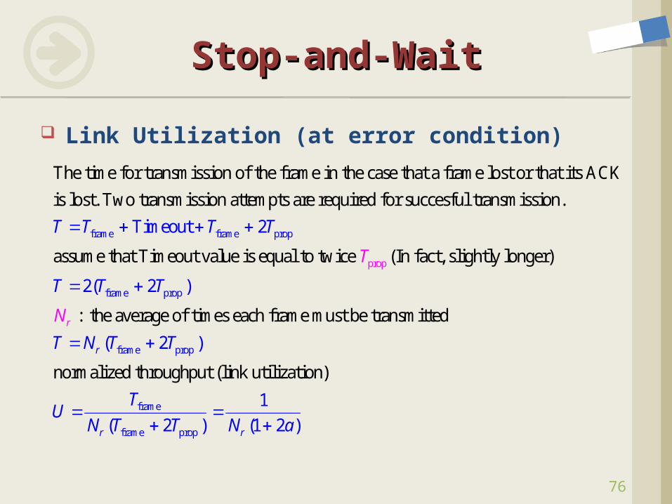
The time for transmission of the frame in the case that a frame lost or that its ACK
is lost. Two transmission attempts are required for succesful transmission
Timeout 2
.
assume that
T T T T
frame prop
frame prop
f
prop Timeout value is equal to twice (In fact, slightly longer)
: the average of
2( 2 )
( 2
times each frame must be transmitted
normalized throughput (link utilizat
)
ion)
r
r
T
N
T T T
T N T T
TU
rame
frame prop
1
( 2 ) (1 2 )r rN T T N a
Stop-and-WaitStop-and-Wait
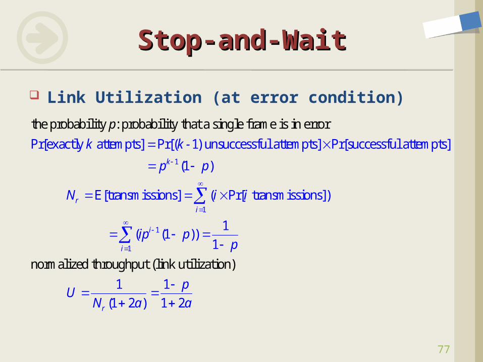
Link Utilization (at error condition)
77
1
Pr[exactly attempts] Pr[( 1) unsuccessful attempts] Pr[successful atte
the probability : probability
mpts]
that a single frame is
in error
(1
E
)k
r
k
N
p
k -
p p
1
1
1
[transmissions] ( Pr[ transmissions])
1 ( (1
normalized throughput (link utilizat
))1
1 1
(
ion)
1 2
) 2
1
i
i
i
r
i i
ip pp
pU
N a a
Stop-and-WaitStop-and-Wait
Link Utilization (at error condition)
78
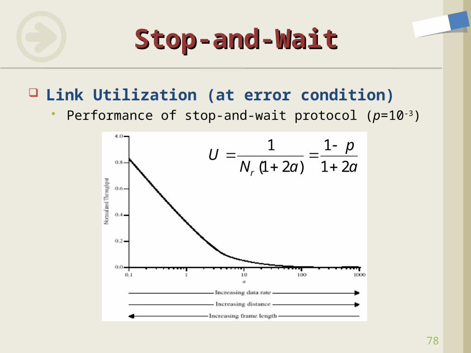
Stop-and-WaitStop-and-Wait
Link Utilization (at error condition) Performance of stop-and-wait protocol (p=10-3)
1 1
(1 2 ) 1 2r
pU
N a a
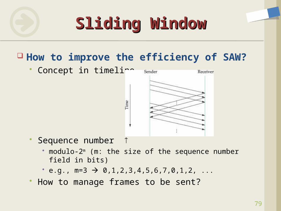
How to improve the efficiency of SAW? Concept in timeline
Sequence number modulo-2m (m: the size of the sequence number field in
bits) e.g., m=3 0,1,2,3,4,5,6,7,0,1,2, ...
How to manage frames to be sent?
Sliding WindowSliding Window
79
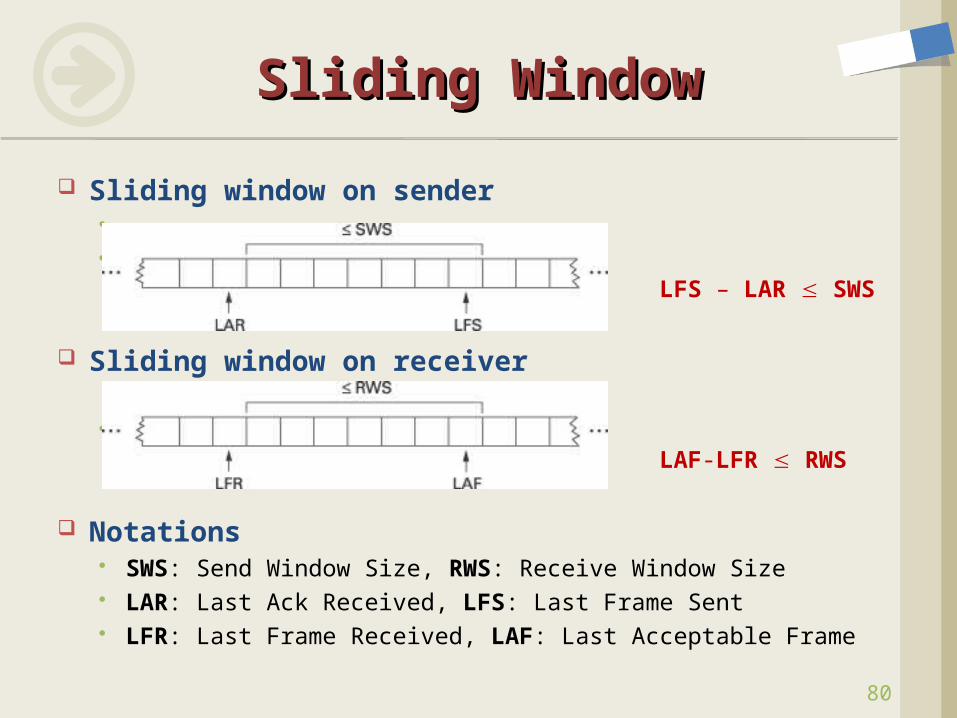
Sliding window on sender
LFS – LAR SWS
Sliding window on receiver
LAF-LFR RWS
Notations SWS: Send Window Size, RWS: Receive Window Size LAR: Last Ack Received, LFS: Last Frame Sent LFR: Last Frame Received, LAF: Last Acceptable Frame
Sliding WindowSliding Window
80
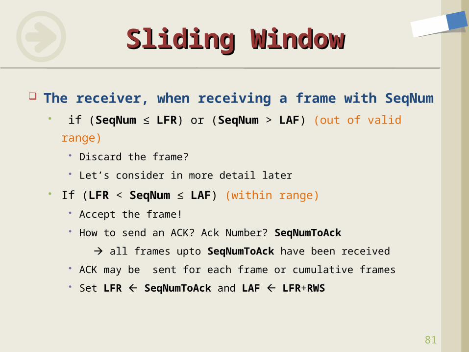
The receiver, when receiving a frame with
SeqNum if (SeqNum ≤ LFR) or (SeqNum > LAF) (out of valid range)
Discard the frame?
Let’s consider in more detail later
If (LFR < SeqNum ≤ LAF) (within range) Accept the frame!
How to send an ACK? Ack Number? SeqNumToAck
all frames upto SeqNumToAck have been received
ACK may be sent for each frame or cumulative frames
Set LFR SeqNumToAck and LAF LFR+RWS
Sliding WindowSliding Window
81
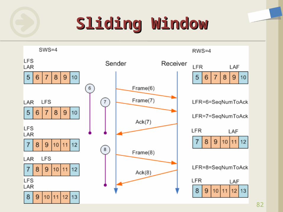
Sliding WindowSliding Window
82
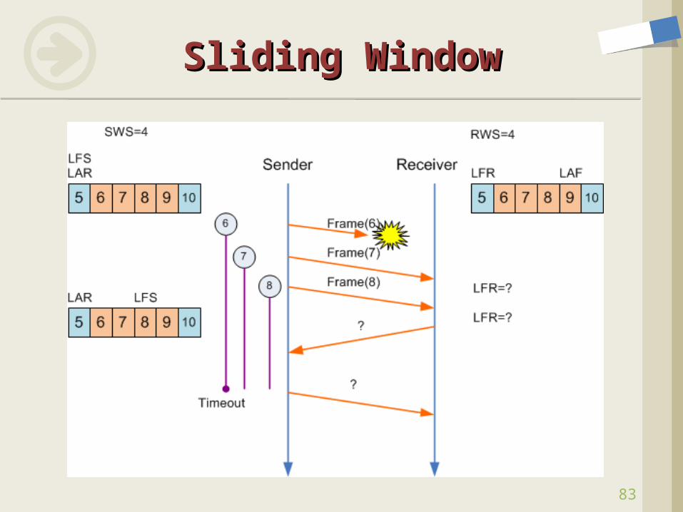
Sliding WindowSliding Window
83
Design Issues When the receiver receives the frame with
(LFR<SeqNum≤LAF) but (SeqNum ≠ LFR+1) ACK? AckNum? Negative ACK(NAK)? Selective ACK(SACK)? Pros and Cons?
When the timer for the lost frame expires, Send the frame only? Send the frame and the subsequent frames that
have been sent together? Pros and Cons?
Sliding WindowSliding Window
84
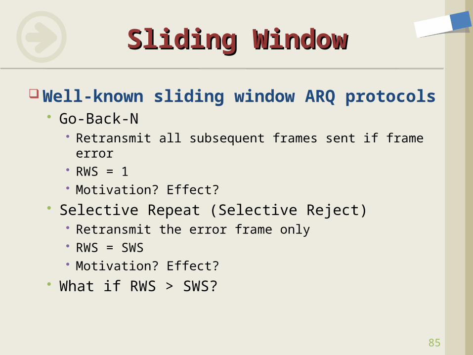
Well-known sliding window ARQ protocols Go-Back-N
Retransmit all subsequent frames sent if frame error RWS = 1 Motivation? Effect?
Selective Repeat (Selective Reject) Retransmit the error frame only RWS = SWS Motivation? Effect?
What if RWS > SWS?
Sliding WindowSliding Window
85
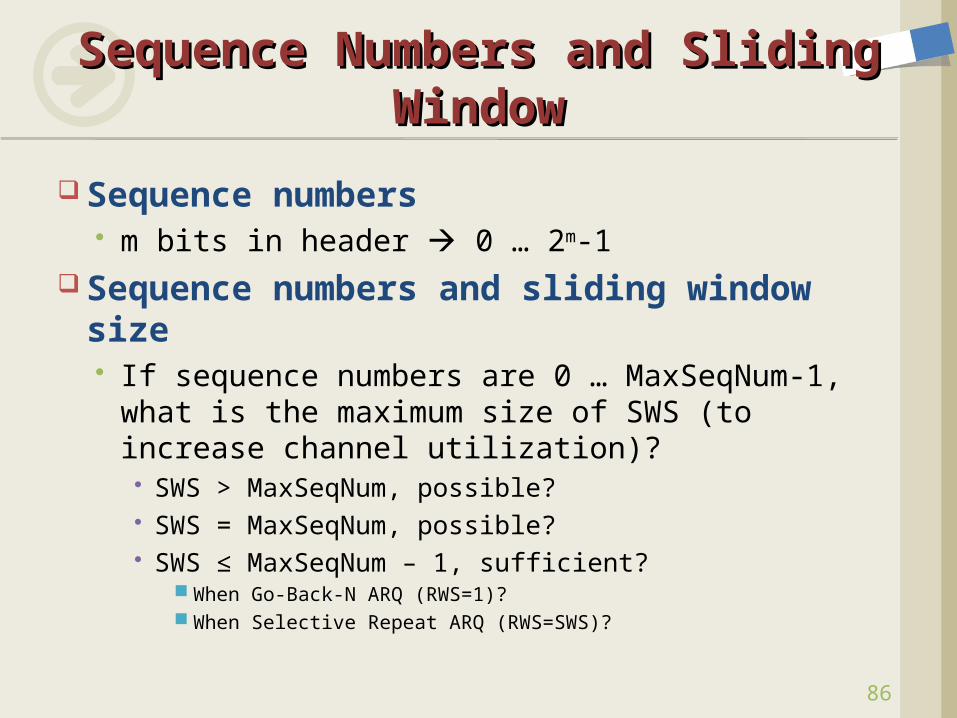
Sequence numbers m bits in header 0 … 2m-1
Sequence numbers and sliding window size If sequence numbers are 0 … MaxSeqNum-1,
what is the maximum size of SWS (to increase channel utilization)?
SWS > MaxSeqNum, possible? SWS = MaxSeqNum, possible? SWS ≤ MaxSeqNum – 1, sufficient?
When Go-Back-N ARQ (RWS=1)? When Selective Repeat ARQ (RWS=SWS)?
Sequence Numbers and Sequence Numbers and Sliding WindowSliding Window
86
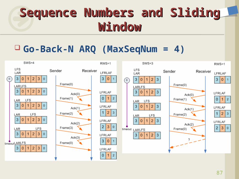
Go-Back-N ARQ (MaxSeqNum = 4)
Sequence Numbers and Sequence Numbers and Sliding WindowSliding Window
87
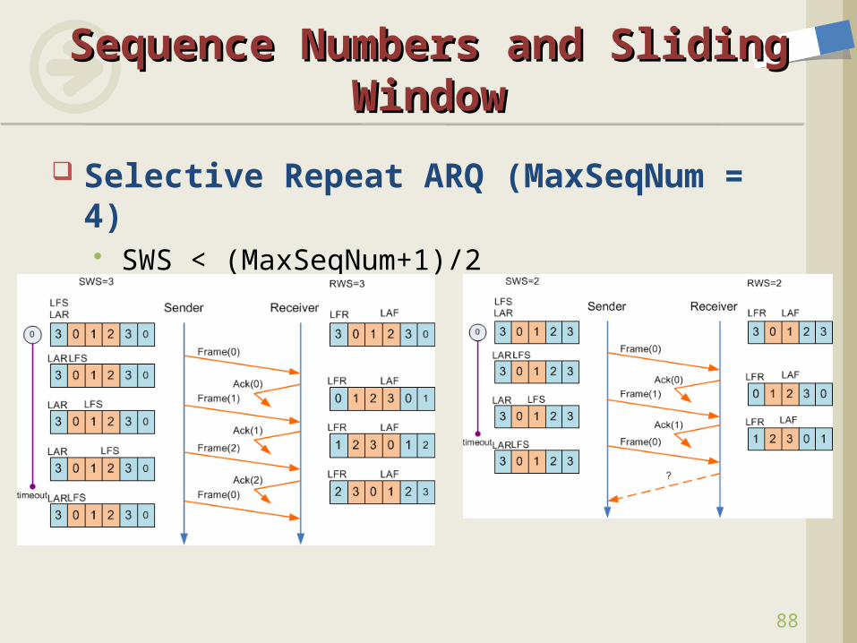
Selective Repeat ARQ (MaxSeqNum = 4) SWS < (MaxSeqNum+1)/2
Sequence Numbers and Sequence Numbers and Sliding WindowSliding Window
88
89
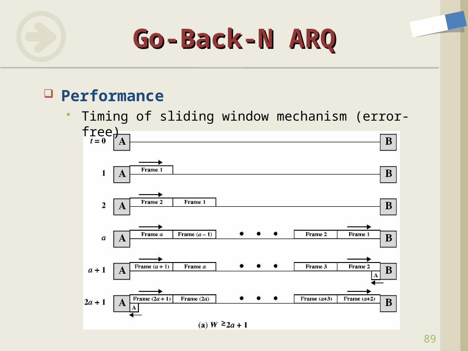
Go-Back-N ARQGo-Back-N ARQ
Performance Timing of sliding window mechanism (error-free)
≥
90
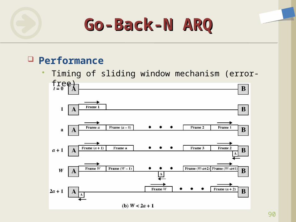
Go-Back-N ARQGo-Back-N ARQ
Performance Timing of sliding window mechanism (error-free)
91
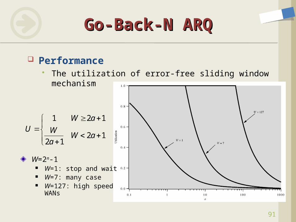
Go-Back-N ARQGo-Back-N ARQ
Performance The utilization of error-free sliding window mechanism
1 2 1
2 12 1
W aU W
W aa
W=2n-1 W=1: stop and wait W=7: many case W=127: high speed
WANs
92
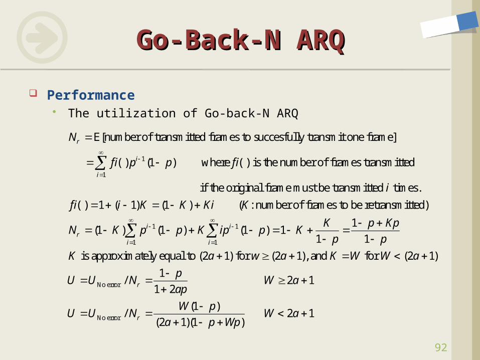
1
1
E[number of transmitted frames to succesfully transmit one frame]
( ) (1 ) where ( ) is the number of frames transmitted
if the
r
i
i
N
f i p p f i
1 1
1 1
original frame must be transmitted times.
( ) 1 ( 1) (1 ) ( : number of frames to be retransmitted)
1(1 ) (1 ) (1 ) 1
1 1
is approximately equal to
i ir
i i
i
f i i K K Ki K
K p KpN K p p K ip p K
p p
K
No error
No error
(2 1) for (2 1), and for (2 1)
1/ 2 1
1 2
(1 )/ 2 1
(2 1)(1 )
r
r
a w a K W W a
pU U N W a
ap
W pU U N W a
a p Wp
Performance The utilization of Go-back-N ARQ
Go-Back-N ARQGo-Back-N ARQ
93
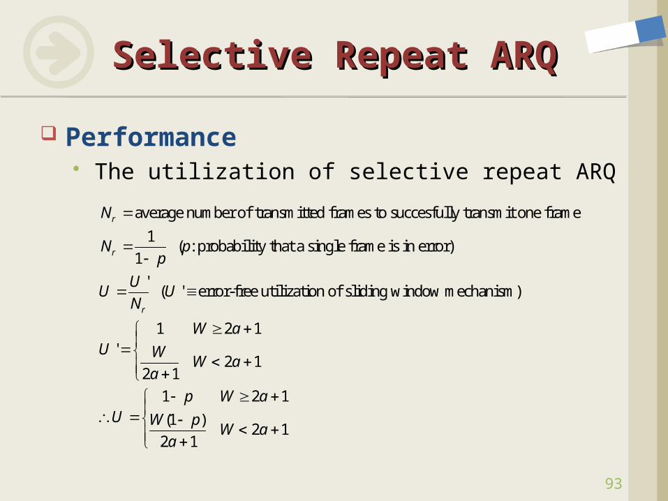
average number of transmitted frames to succesfully transmit one frame
1 ( : probability that a single frame is in error)
1
' ( ' error-free utilization of sliding window mechanism)
1 2'
r
r
r
N
N pp
UU U
N
WU
1
2 12 1
1 2 1
(1 )2 1
2 1
a
WW a
a
p W aU W p
W aa
Performance The utilization of selective repeat ARQ
Selective Repeat ARQSelective Repeat ARQ
94
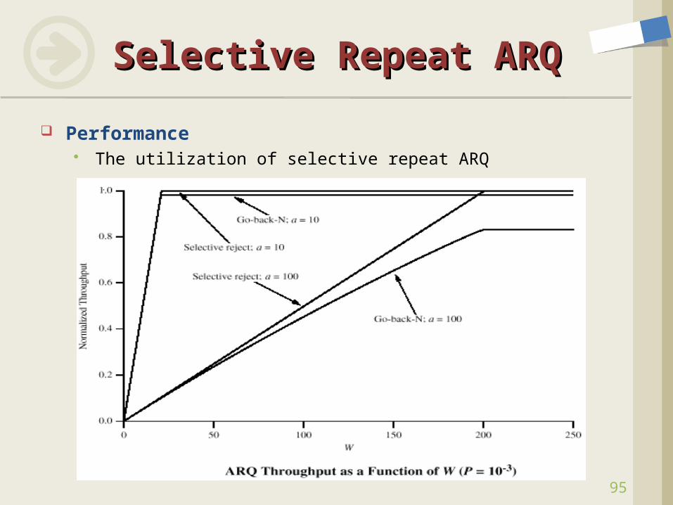
Selective Repeat ARQSelective Repeat ARQ
Performance The utilization of selective repeat ARQ
95
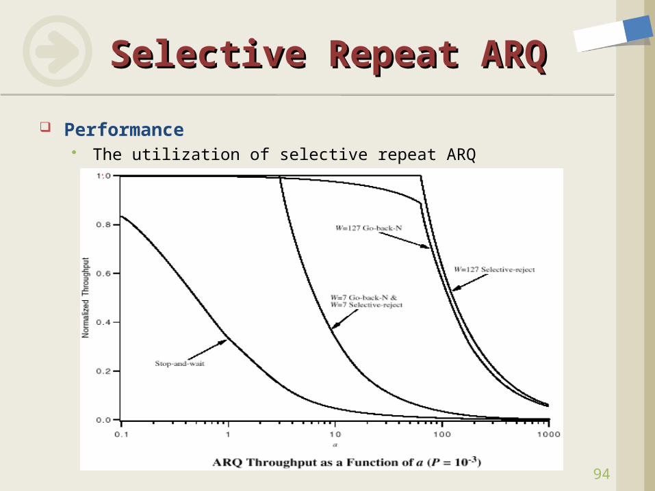
Selective Repeat ARQSelective Repeat ARQ
Performance The utilization of selective repeat ARQ
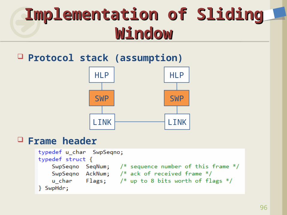
Protocol stack (assumption)
Frame header
Implementation of Sliding Implementation of Sliding WindowWindow
96
HLP
LINK
HLP
LINK
SWP SWP
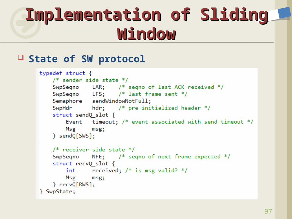
State of SW protocol
Implementation of Sliding Implementation of Sliding WindowWindow
97
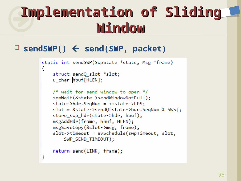
sendSWP() send(SWP, packet)
Implementation of Sliding Implementation of Sliding WindowWindow
98
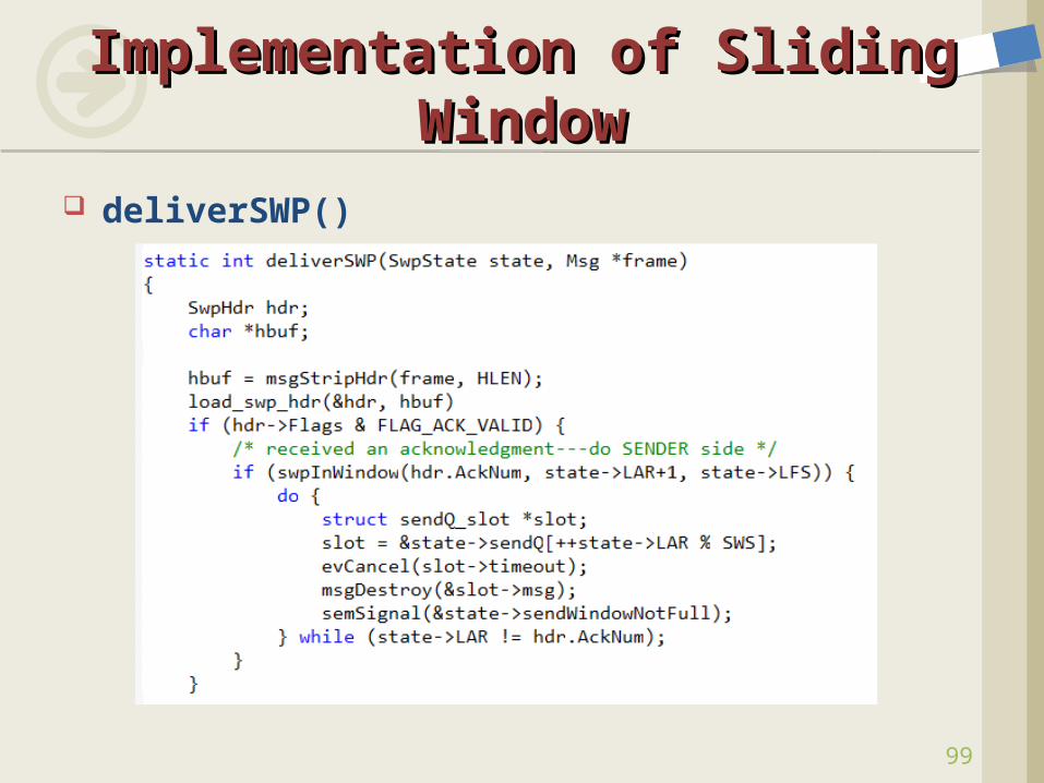
deliverSWP()
Implementation of Sliding Implementation of Sliding WindowWindow
99
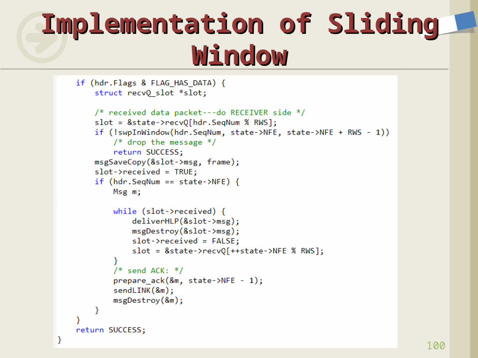
Implementation of Sliding Implementation of Sliding WindowWindow
100
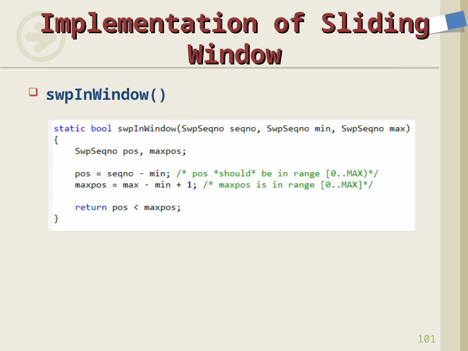
swpInWindow()
Implementation of Sliding Implementation of Sliding WindowWindow
101
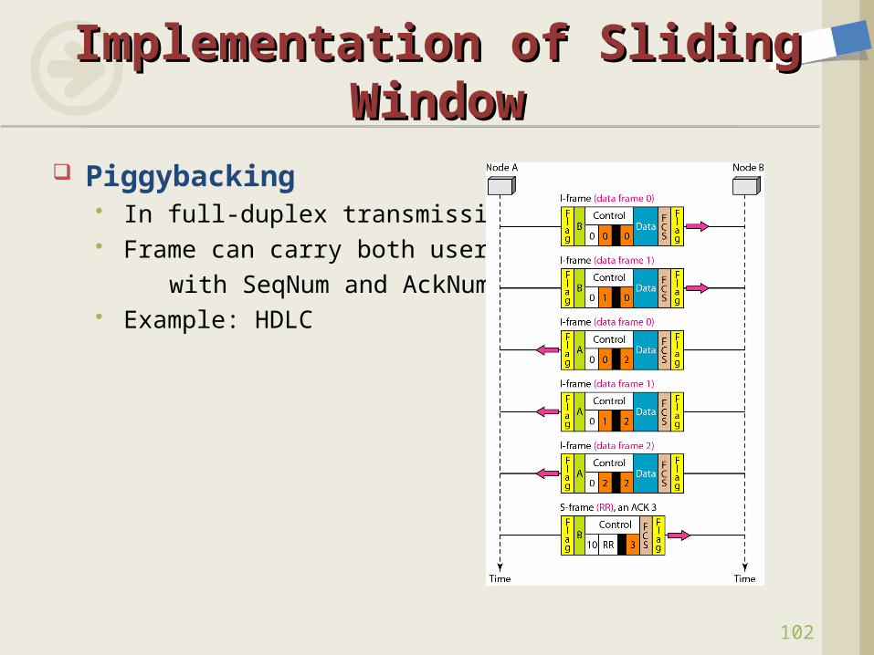
Piggybacking In full-duplex transmission Frame can carry both user data with SeqNum and AckNum Example: HDLC
Implementation of Sliding Implementation of Sliding WindowWindow
102
To reliably deliver frames across an unreliable link
To preserve the order in which frames are transmitted
To support flow control A feedback mechanism by which the
receiver is able to throttle the sender
The Role of Sliding Window The Role of Sliding Window AlgorithmAlgorithm
103
104
Signals Hardware Building Blocks Encoding Framing Error Detection Reliable Transmission Project #1 Ethernet Wireless Assignment #2
ContentsContents
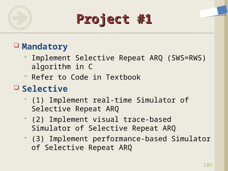
Mandatory Implement Selective Repeat ARQ (SWS=RWS)
algorithm in C Refer to Code in Textbook
Selective (1) Implement real-time Simulator of Selective
Repeat ARQ (2) Implement visual trace-based Simulator of
Selective Repeat ARQ (3) Implement performance-based Simulator
of Selective Repeat ARQ
Project #1Project #1
105
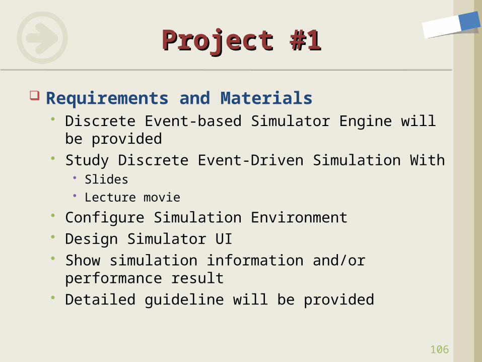
Requirements and Materials Discrete Event-based Simulator Engine will be
provided Study Discrete Event-Driven Simulation With
Slides Lecture movie
Configure Simulation Environment Design Simulator UI Show simulation information and/or
performance result Detailed guideline will be provided
Project #1Project #1
106
107
Signals Hardware Building Blocks Encoding Framing Error Detection Reliable Transmission Project #1 Ethernet
IEEE Standards Physical Properties Frame Format Transmitter Algorithm Evolution of Ethernet
Wireless Assignment #2
ContentsContents
108
IEEE StandardsIEEE Standards
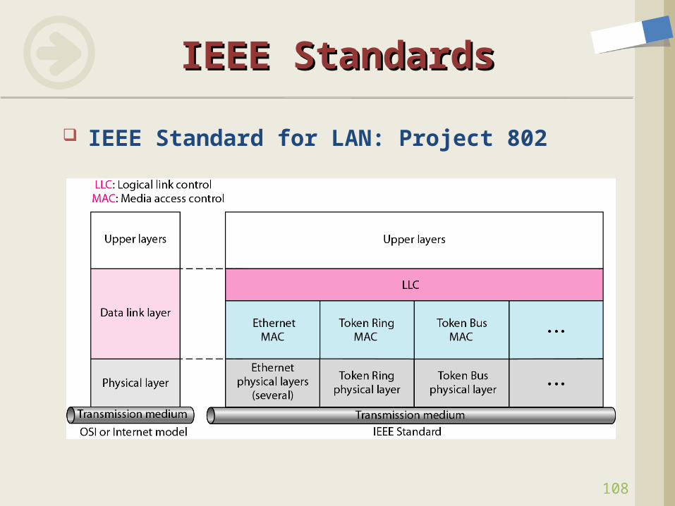
IEEE Standard for LAN: Project 802
109
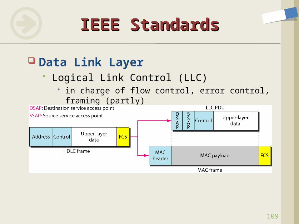
IEEE StandardsIEEE Standards
Data Link Layer Logical Link Control (LLC)
in charge of flow control, error control, framing (partly)
110
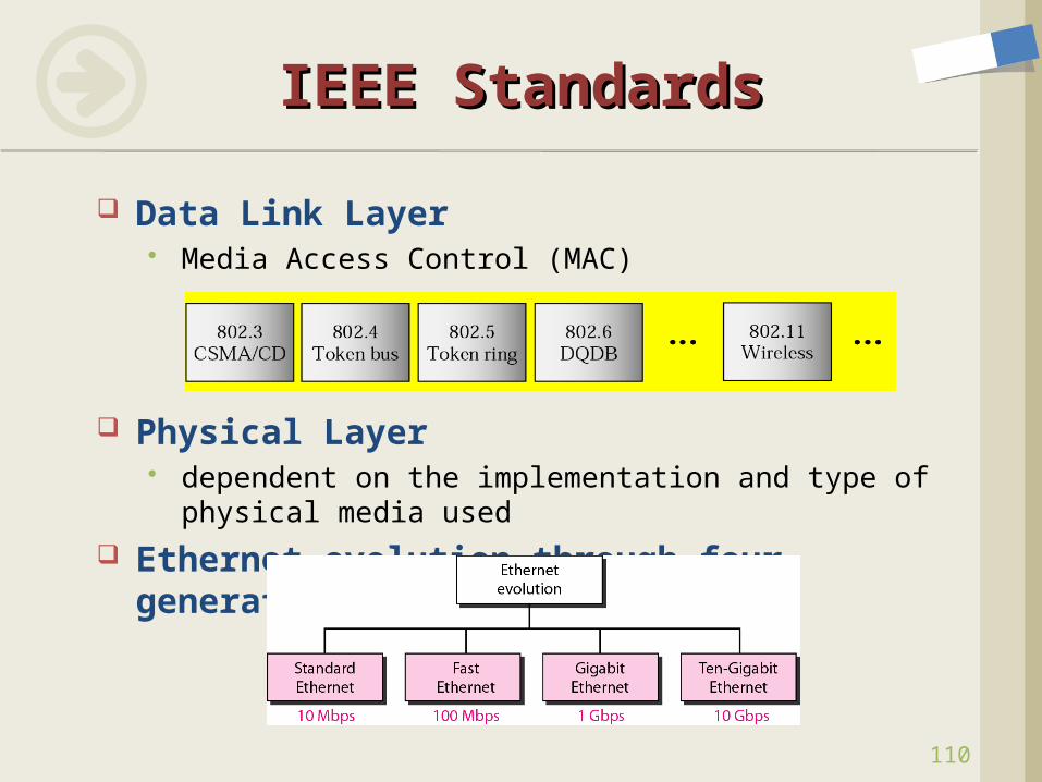
IEEE StandardsIEEE Standards
Data Link Layer Media Access Control (MAC)
Physical Layer dependent on the implementation and type of physical
media used Ethernet evolution through four
generations
111
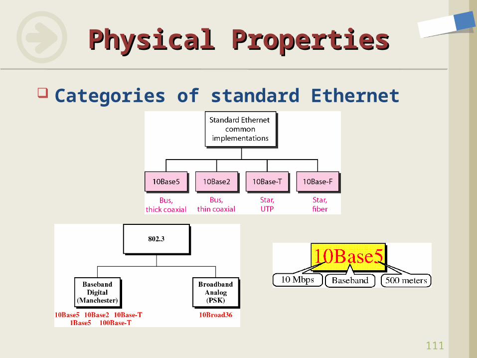
Physical PropertiesPhysical Properties
Categories of standard Ethernet
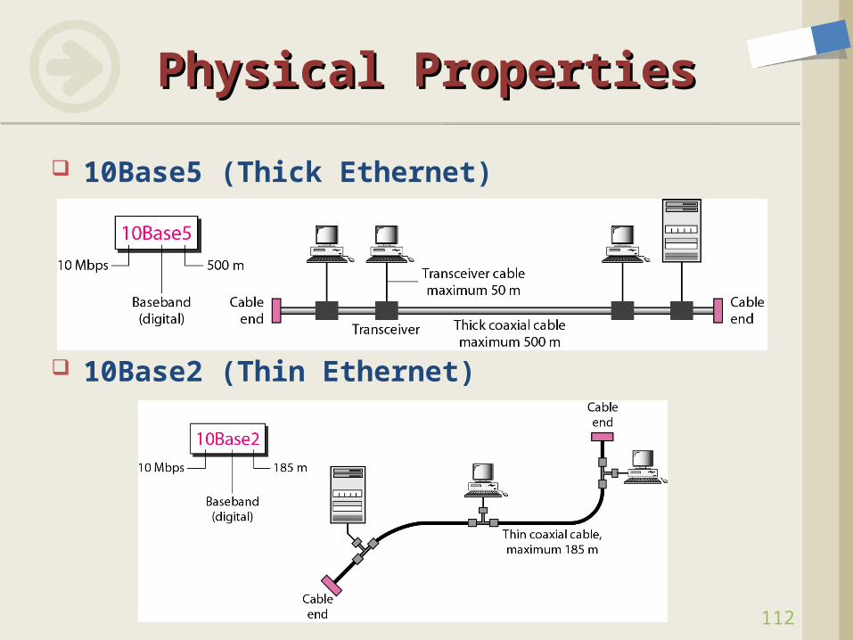
10Base5 (Thick Ethernet)
10Base2 (Thin Ethernet)
Physical PropertiesPhysical Properties
112
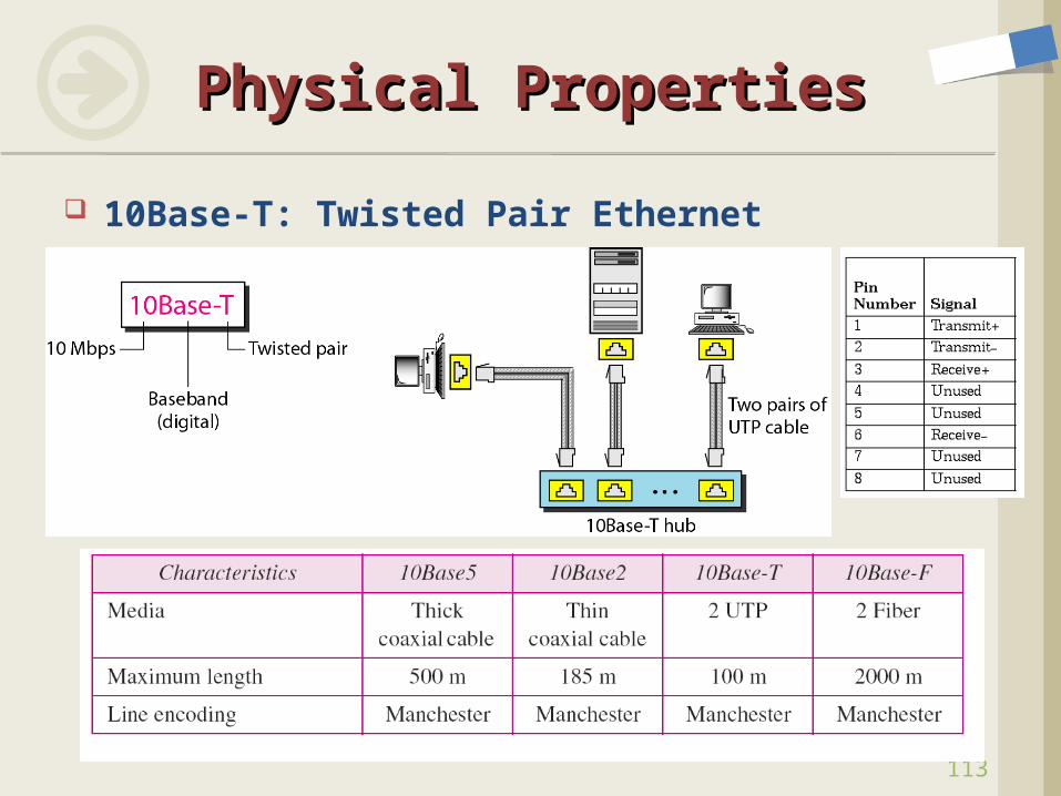
10Base-T: Twisted Pair Ethernet
Physical PropertiesPhysical Properties
113
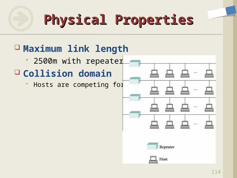
Maximum link length 2500m with repeaters
Collision domain Hosts are competing for access
Physical PropertiesPhysical Properties
114
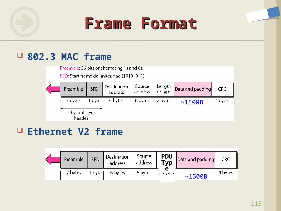
802.3 MAC frame
Ethernet V2 frame
115
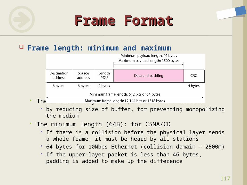
Frame FormatFrame Format
~1500B
PDUType ~1500B
116
Frame FormatFrame Format
Preamble (7B) for synchronization of receiver’s H/W with the incoming signal bit pattern : 10101010….. Added at the physical layer (not formal part of the frame)
SFD (1B: 10101011) indicates a last chance for synchronization
Destination/Source address (6B) serial number on the NIC (unique) Broadcast address (only for DA) : all 6 bytes set to 1
Length/Type (2B) < 1518 (802.3): length field length of data field > 1536 (V2): the type of the PDU packet encapsulated in the
frame Data (46-1500B) CRC (4B): CRC-32
117
Frame FormatFrame Format
Frame length: minimum and maximum
The maximum length (1518B): historical reasons by reducing size of buffer, for preventing monopolizing the
medium The minimum length (64B): for CSMA/CD
If there is a collision before the physical layer sends a whole frame, it must be heard by all stations
64 bytes for 10Mbps Ethernet (collision domain = 2500m) If the upper-layer packet is less than 46 bytes, padding is
added to make up the difference
118
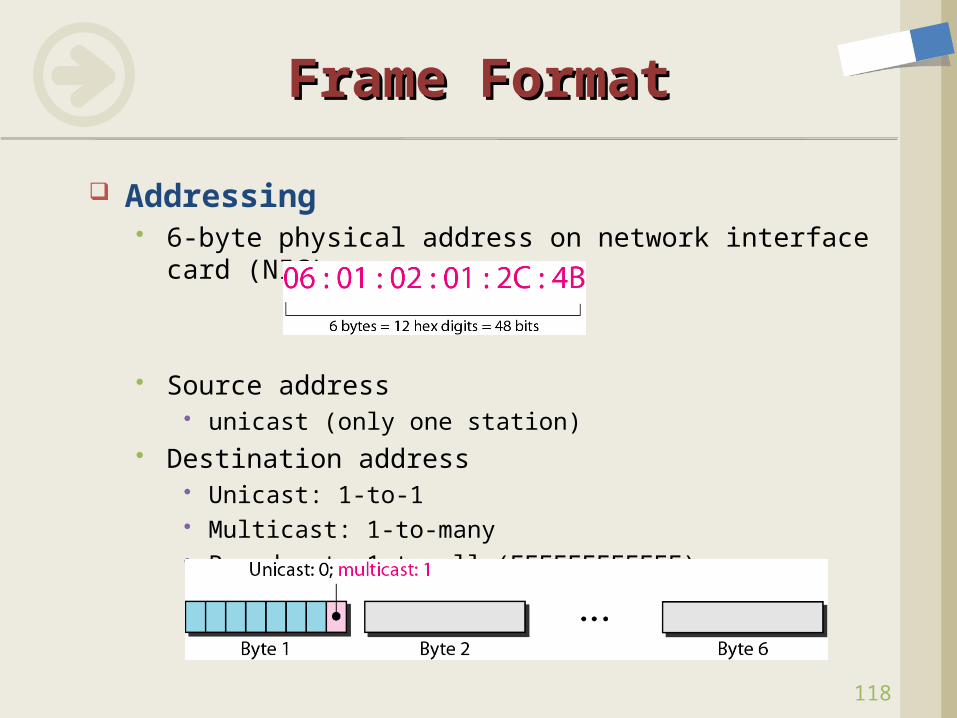
Frame FormatFrame Format
Addressing 6-byte physical address on network interface card
(NIC)
Source address unicast (only one station)
Destination address Unicast: 1-to-1 Multicast: 1-to-many Broadcast: 1-to-all (FFFFFFFFFFFF)
Who, When can send data? Random Access
CSMA/CD, CSMA/CA Controlled Access
Token Bus, Token Ring Reservation-based Polling-based
Channelization (Data Link Layer Techniques) FDMA, TDMA, CDMA
Access Control MethodsAccess Control Methods
119
120
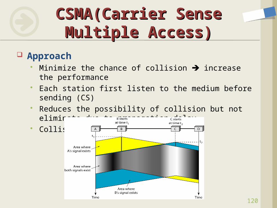
CSMA(Carrier Sense CSMA(Carrier Sense Multiple Access)Multiple Access)
Approach Minimize the chance of collision increase the
performance Each station first listen to the medium before sending
(CS) Reduces the possibility of collision but not eliminate
due to propagation delay Collision in CSMA
121
CSMACSMA
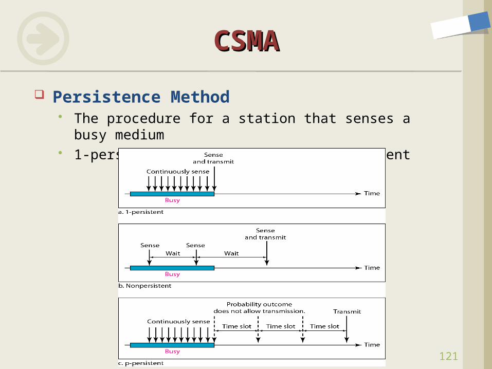
Persistence Method The procedure for a station that senses a busy
medium 1-persistent, nonpersistent, p-persistent
122
CSMACSMA
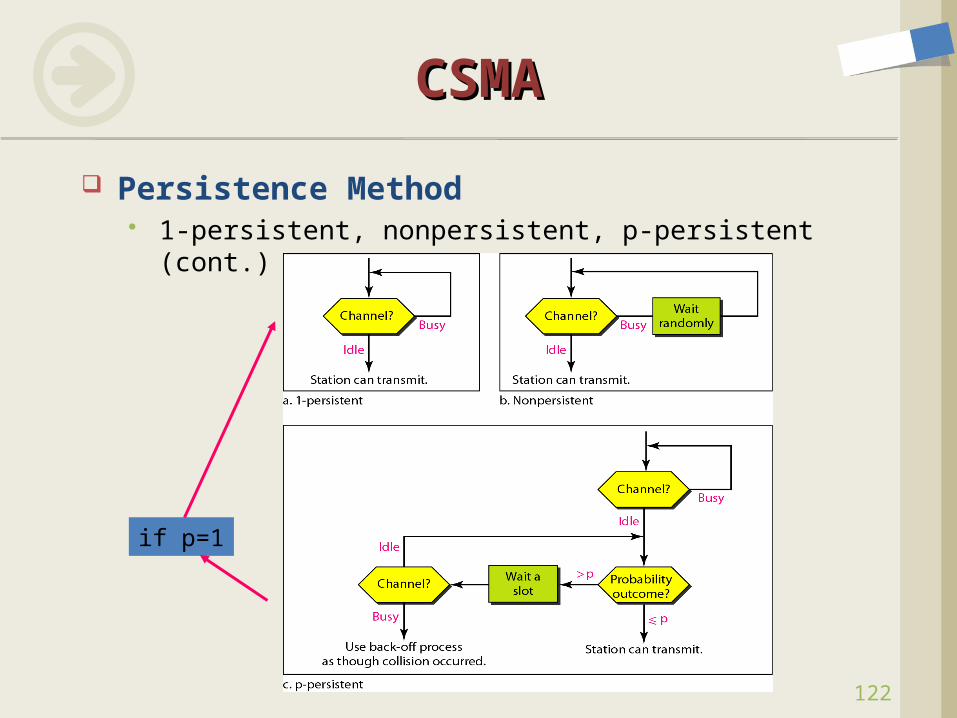
Persistence Method 1-persistent, nonpersistent, p-persistent (cont.)
if p=1
123
CSMA/CD (Collision CSMA/CD (Collision Detection)Detection)
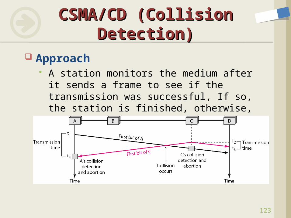
Approach A station monitors the medium after it sends
a frame to see if the transmission was successful, If so, the station is finished, otherwise, the frame is sent again
124
CSMA/CDCSMA/CD
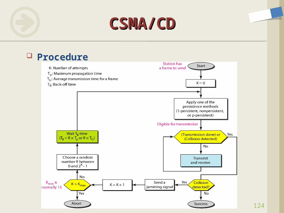
Procedure
125
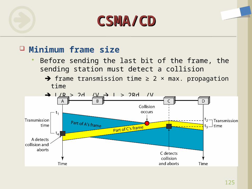
CSMA/CDCSMA/CD
Minimum frame size Before sending the last bit of the frame, the sending
station must detect a collision frame transmission time ≥ 2 × max. propagation time L/R ≥ 2dmax/V L ≥ 2Rdmax/V
126
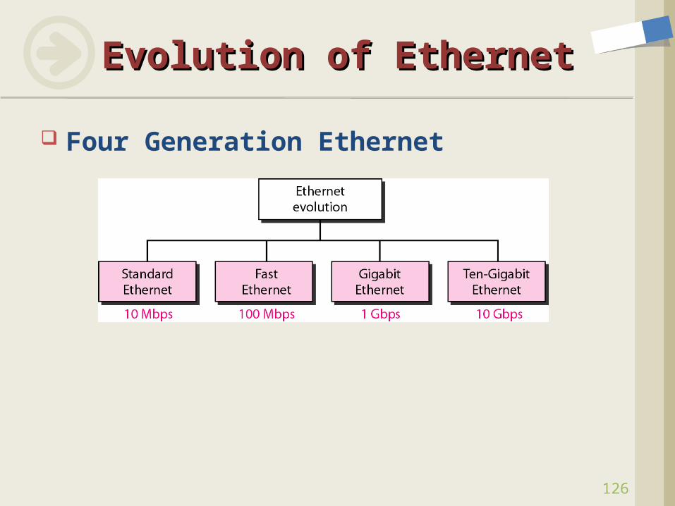
Evolution of EthernetEvolution of Ethernet
Four Generation Ethernet
127
Fast EthernetFast Ethernet
Goals Upgrade the data rate to 100 Mbps Make it compatible with Standard Ethernet Keep the same 48-bit address Keep the same frame format Keep the same minimum and maximum frame length
Access Method Half duplex: CSMA/CD (collision domain = 250m WHY?) Full duplex: no CSMA/CD The implementations keep CSMA/CD for backward compatibility
Minimum and maximum frame size: same as those of Ethernet

128
Fast EthernetFast Ethernet
Autonegotiation Allows two devices to negotiate the mode or data rate
of operation In order to allow incompatible devices to connect one
another In order to allow one device to have multiple capabilities In order to allow a station to check a hub’s capabilities
Implementations
129
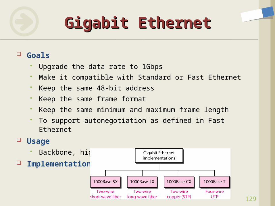
Gigabit EthernetGigabit Ethernet
Goals Upgrade the data rate to 1Gbps Make it compatible with Standard or Fast Ethernet Keep the same 48-bit address Keep the same frame format Keep the same minimum and maximum frame length To support autonegotiation as defined in Fast Ethernet
Usage Backbone, high-speed links
Implementation
130
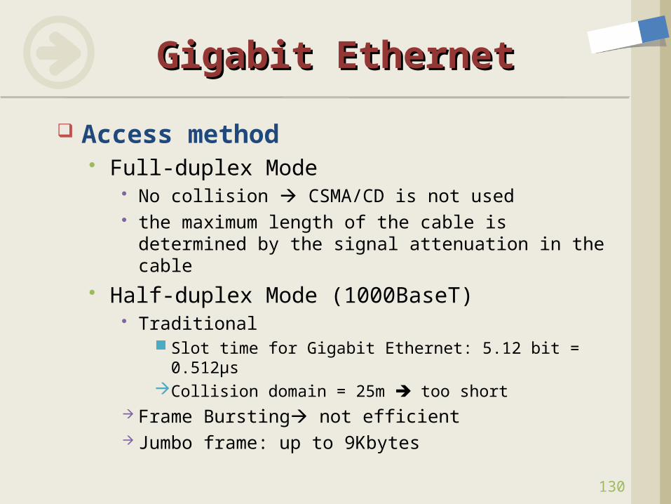
Gigabit EthernetGigabit Ethernet
Access method Full-duplex Mode
No collision CSMA/CD is not used the maximum length of the cable is determined by
the signal attenuation in the cable Half-duplex Mode (1000BaseT)
Traditional Slot time for Gigabit Ethernet: 5.12 bit = 0.512μsCollision domain = 25m too short
Frame Bursting not efficient Jumbo frame: up to 9Kbytes
131
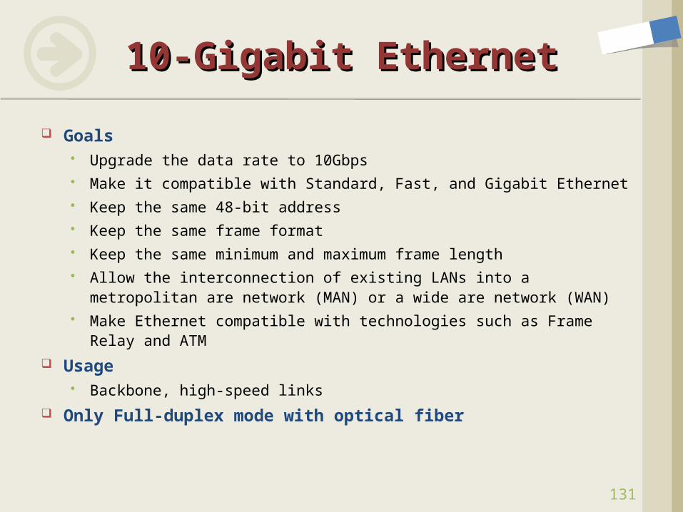
10-Gigabit Ethernet10-Gigabit Ethernet
Goals Upgrade the data rate to 10Gbps Make it compatible with Standard, Fast, and Gigabit Ethernet Keep the same 48-bit address Keep the same frame format Keep the same minimum and maximum frame length Allow the interconnection of existing LANs into a metropolitan
are network (MAN) or a wide are network (WAN) Make Ethernet compatible with technologies such as Frame
Relay and ATM
Usage Backbone, high-speed links
Only Full-duplex mode with optical fiber
Capture packets in Ethernet LAN Check the version of Ethernet Check the fields of Ethernet
frame Framing sequences Addresses Size/Type CRC
Packet Capture with Packet Capture with WiresharkWireshark
132
133
Signals Hardware Building Blocks Encoding Framing Error Detection Reliable Transmission Project #1 Ethernet Wireless
Overview Bluetooth (802.15.1) Wi-Fi (802.11): Physical, CSMA/CA, Architecture, Frame Format WiMax Cell Phone Technologies
Assignment #2
ContentsContents
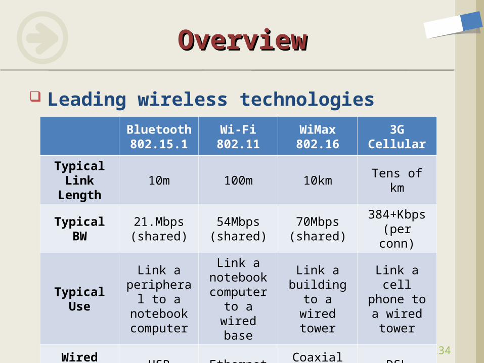
Leading wireless technologies
OverviewOverview
134
Bluetooth802.15.1
Wi-Fi802.11
WiMax802.16
3G Cellular
Typical Link
Length10m 100m 10km Tens of km
Typical BW
21.Mbps(shared)
54Mbps(shared)
70Mbps(shared)
384+Kbps(per conn)
Typical Use
Link a peripheral
to a notebook computer
Link a notebook computer to a wired
base
Link a building to
a wired tower
Link a cell phone to a
wired tower
Wired Analogy
USB EthernetCoaxial cable
DSL
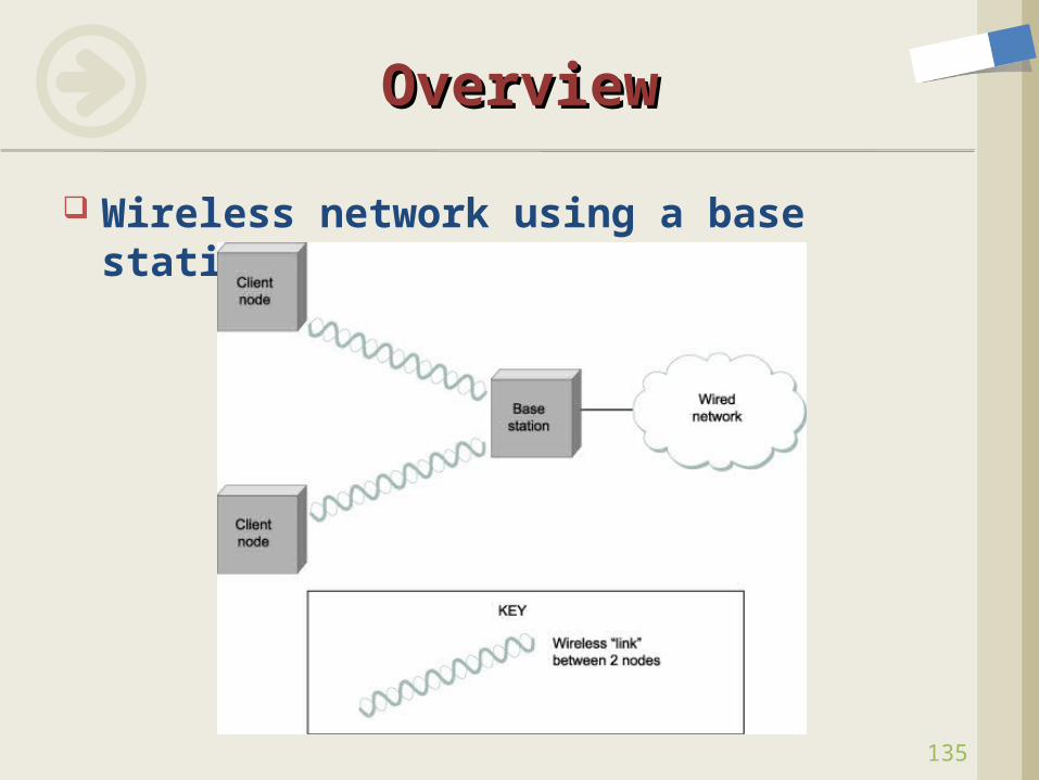
Wireless network using a base station
OverviewOverview
135
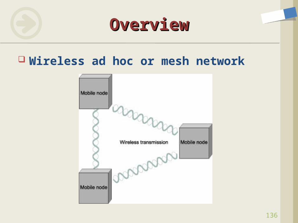
Wireless ad hoc or mesh network
OverviewOverview
136
137
BluetoothBluetooth
Features WLAN technology designed to connect devices of different
functions such as telephones, notebooks, computers, cameras, printers, coffee makers, and so on.
A Bluetooth LAN is an ad hoc network formed spontaneously Applications
Peripheral devices: wireless mouse or keyboard Monitoring devices: sensor devices, home security devices
Origin of name Harald Blaatand, king of Denmark (a project by the Ericsson Co.)
Standard IEEE 802.15.1
138
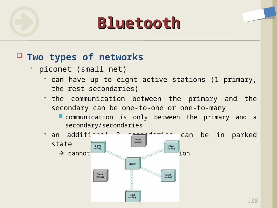
BluetoothBluetooth
Two types of networks piconet (small net)
can have up to eight active stations (1 primary, the rest secondaries)
the communication between the primary and the secondary can be one-to-one or one-to-many
communication is only between the primary and a secondary/secondaries
an additional 8 secondaries can be in parked state cannot take part in communication
139
ArchitectureArchitecture
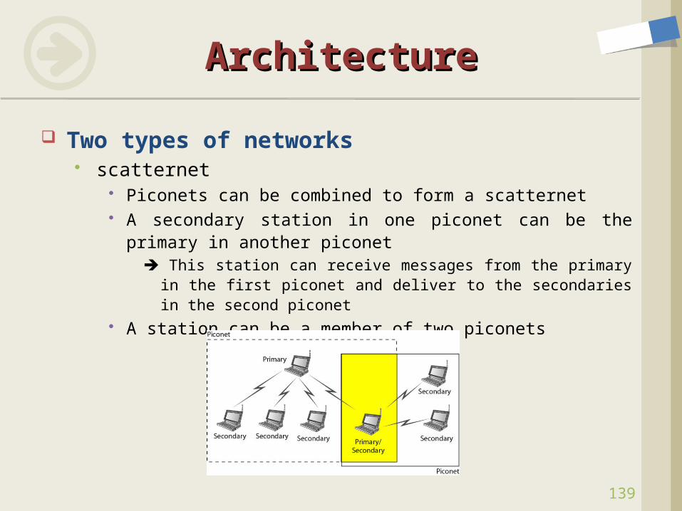
Two types of networks scatternet
Piconets can be combined to form a scatternet A secondary station in one piconet can be the primary in
another piconet This station can receive messages from the primary in the
first piconet and deliver to the secondaries in the second piconet
A station can be a member of two piconets
140
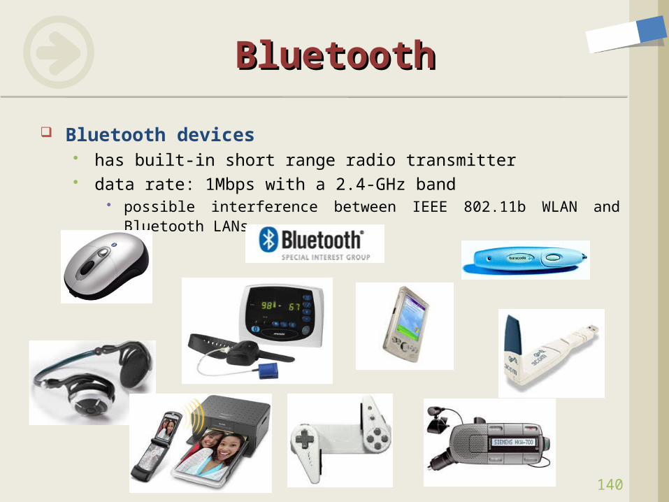
BluetoothBluetooth
Bluetooth devices has built-in short range radio transmitter data rate: 1Mbps with a 2.4-GHz band
possible interference between IEEE 802.11b WLAN and Bluetooth LANs
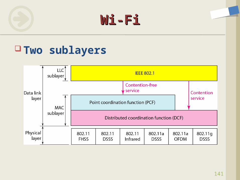
Two sublayers
Wi-FiWi-Fi
141
142
Wi-FiWi-Fi
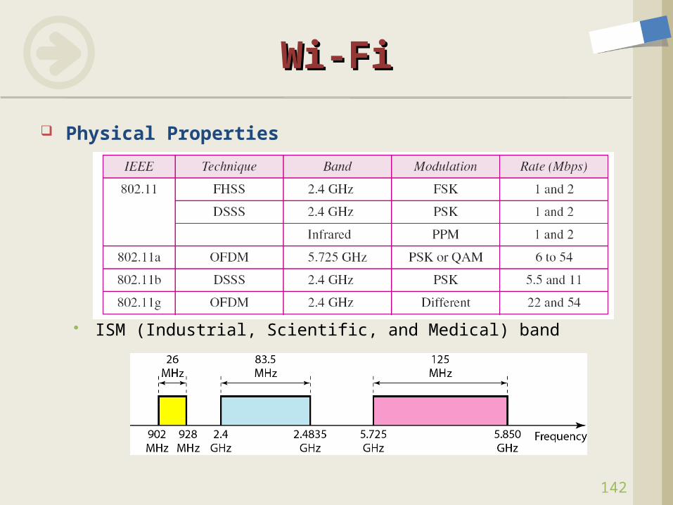
Physical Properties
ISM (Industrial, Scientific, and Medical) band
143
Wi-FiWi-Fi
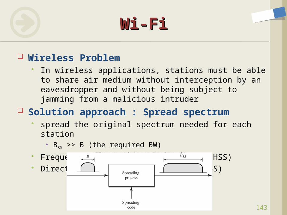
Wireless Problem In wireless applications, stations must be able to share
air medium without interception by an eavesdropper and without being subject to jamming from a malicious intruder
Solution approach : Spread spectrum spread the original spectrum needed for each station
BSS >> B (the required BW)
Frequency hopping spread spectrum (FHSS) Direct Sequence Spread Spectrum (DSSS)
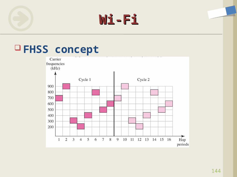
FHSS concept
Wi-FiWi-Fi
144
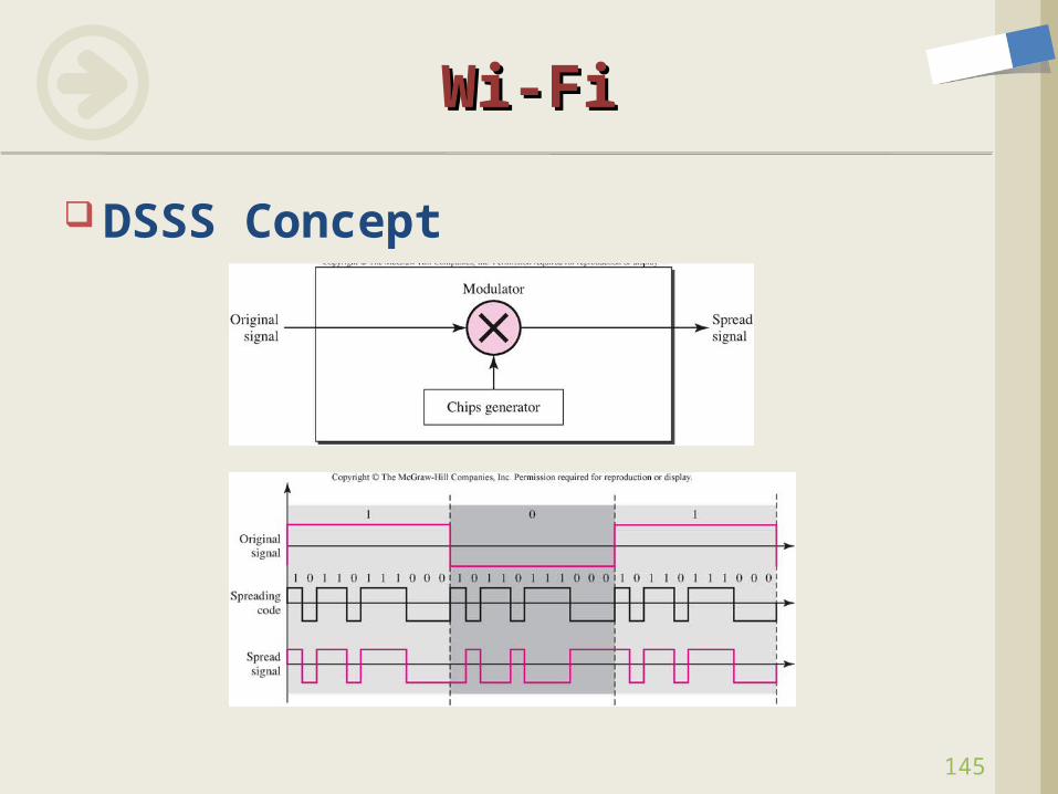
DSSS Concept
Wi-FiWi-Fi
145
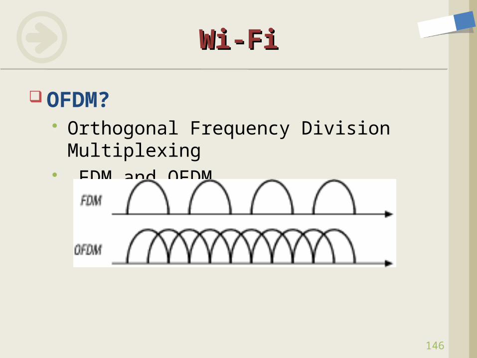
OFDM? Orthogonal Frequency Division
Multiplexing FDM and OFDM
Wi-FiWi-Fi
146
147
Wi-Fi MACWi-Fi MAC
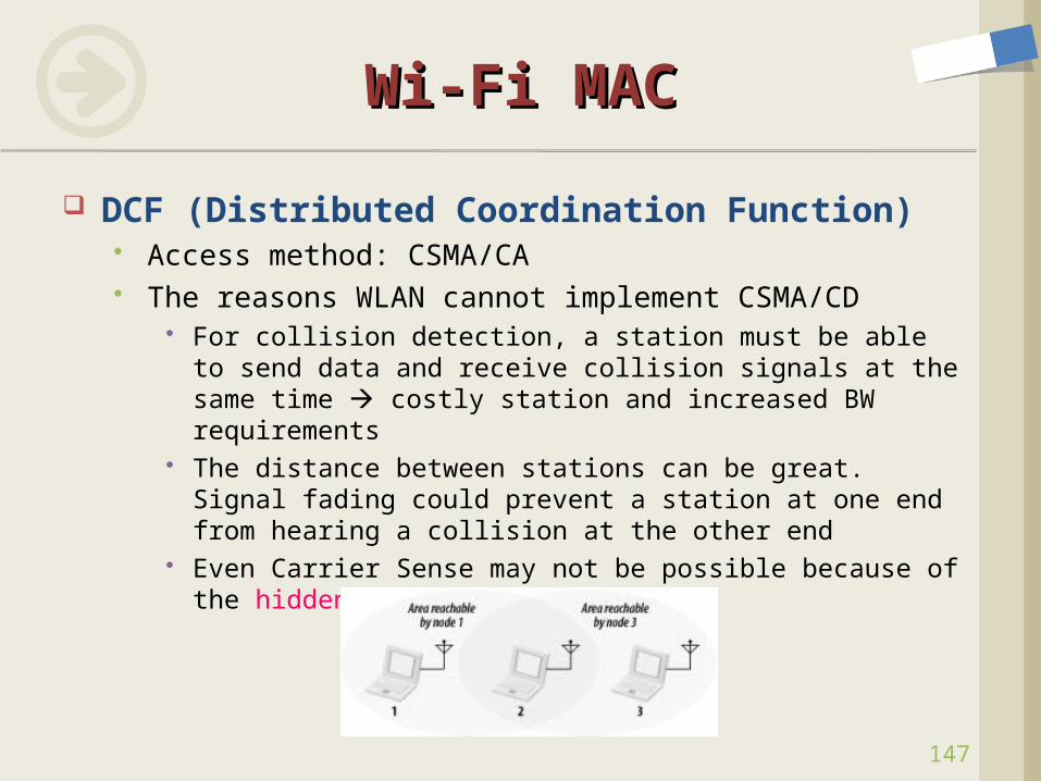
DCF (Distributed Coordination Function) Access method: CSMA/CA The reasons WLAN cannot implement CSMA/CD
For collision detection, a station must be able to send data and receive collision signals at the same time costly station and increased BW requirements
The distance between stations can be great. Signal fading could prevent a station at one end from hearing a collision at the other end
Even Carrier Sense may not be possible because of the hidden station problem
148
Wi-Fi MACWi-Fi MAC
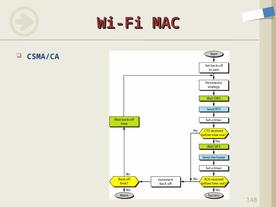
CSMA/CA
149
Wi-Fi MACWi-Fi MAC
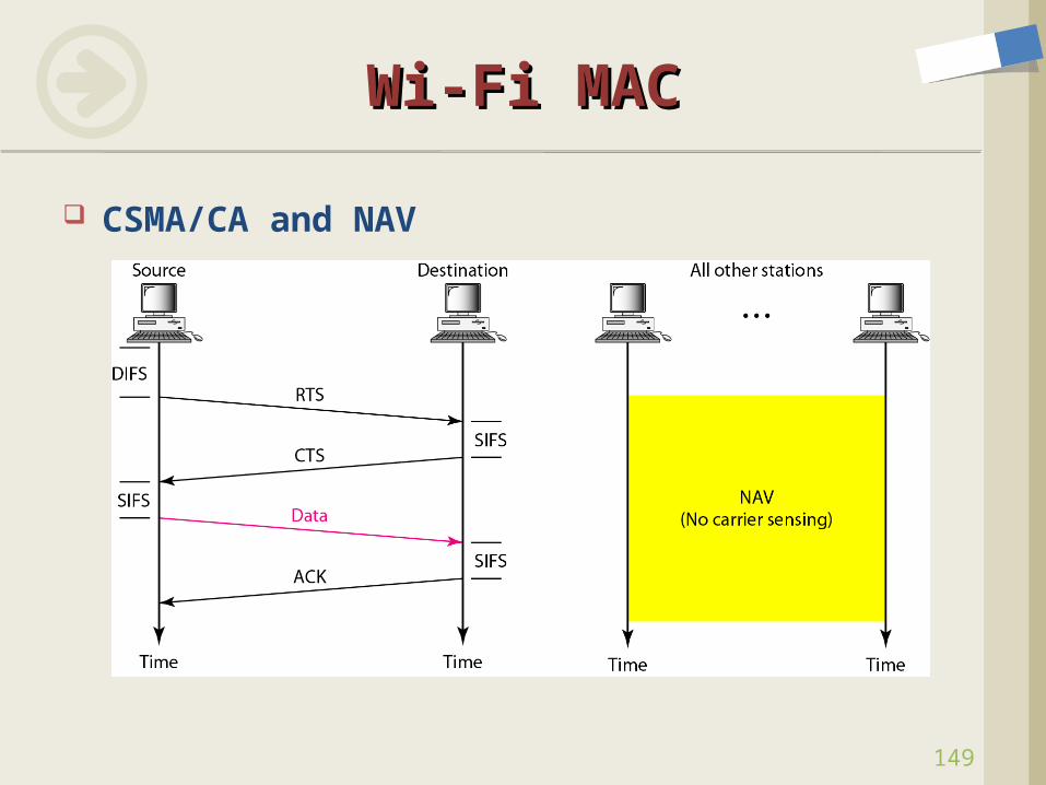
CSMA/CA and NAV
150
Wi-Fi MACWi-Fi MAC
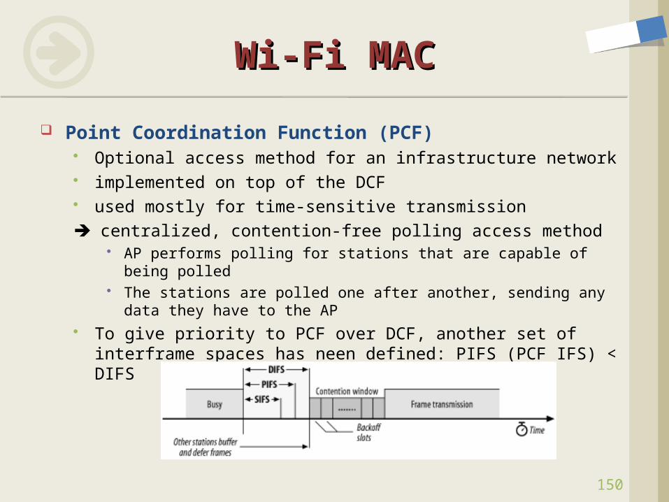
Point Coordination Function (PCF) Optional access method for an infrastructure network implemented on top of the DCF used mostly for time-sensitive transmission centralized, contention-free polling access method
AP performs polling for stations that are capable of being polled The stations are polled one after another, sending any data they
have to the AP To give priority to PCF over DCF, another set of interframe
spaces has neen defined: PIFS (PCF IFS) < DIFS
151
Wi-Fi MACWi-Fi MAC
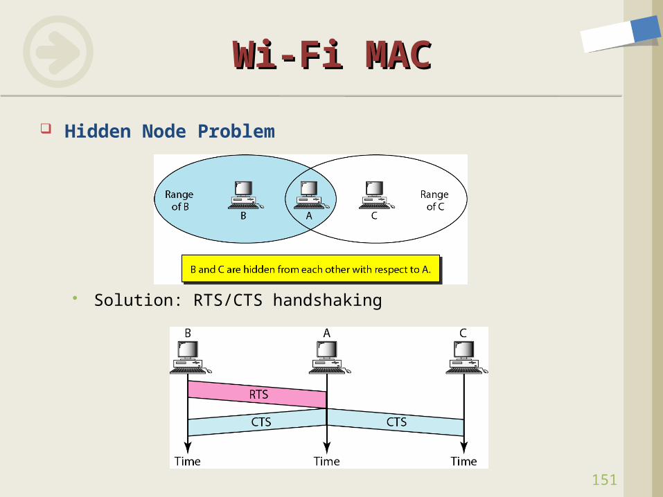
Hidden Node Problem
Solution: RTS/CTS handshaking
152
Wi-Fi MACWi-Fi MAC
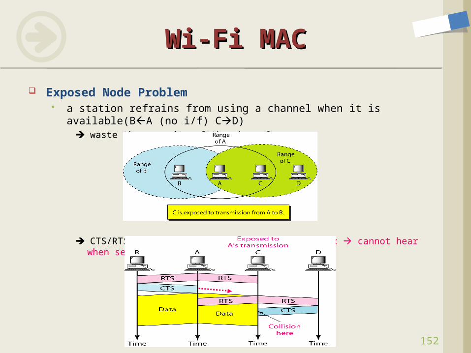
Exposed Node Problem a station refrains from using a channel when it is available(BA (no
i/f) CD) waste the capacity of the channel
CTS/RTS cannot help in this case: half-duplex cannot hear when sending
153
Wi-Fi MACWi-Fi MAC
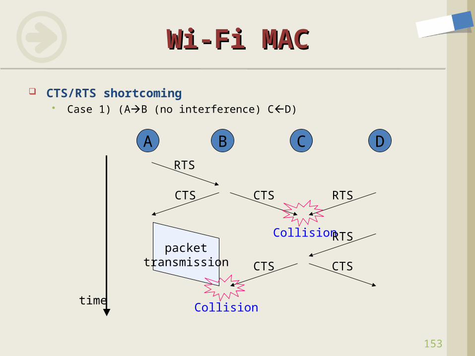
CTS/RTS shortcoming Case 1) (AB (no interference) CD)
A B C DRTS
CTS CTS RTS
Collisionpacket
transmission CTS
RTS
Collision
CTS
time
154
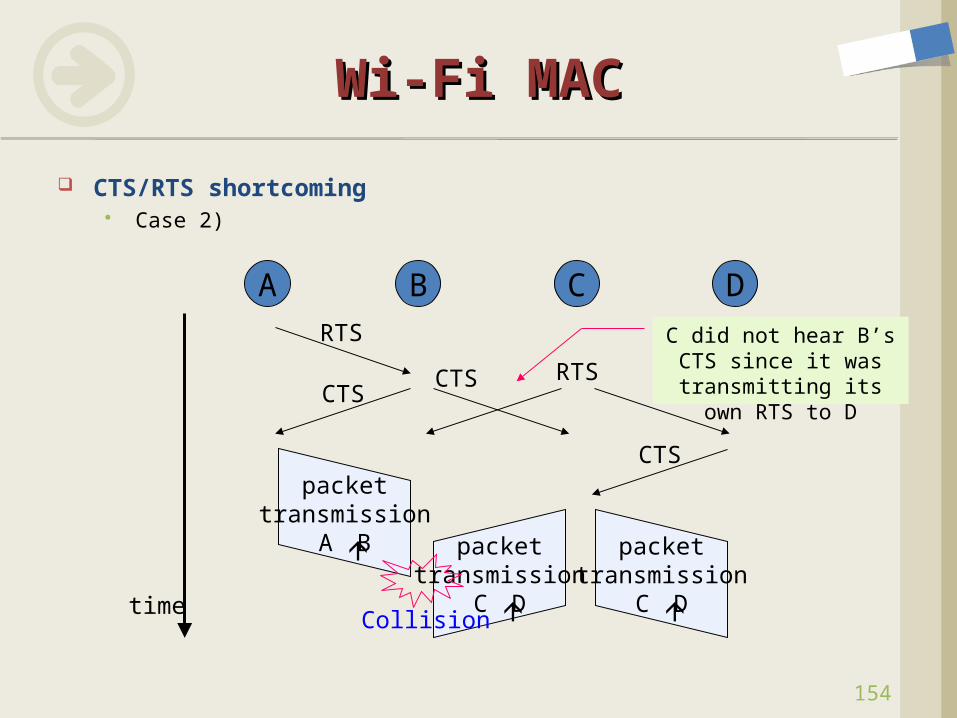
Wi-Fi MACWi-Fi MAC
CTS/RTS shortcoming Case 2)
A B C DRTS
CTSCTS RTS
packettransmission
A B
CTS
time
packettransmission
C D
packettransmission
C DCollision
C did not hear B’s CTS since it was
transmitting its own RTS to D
155
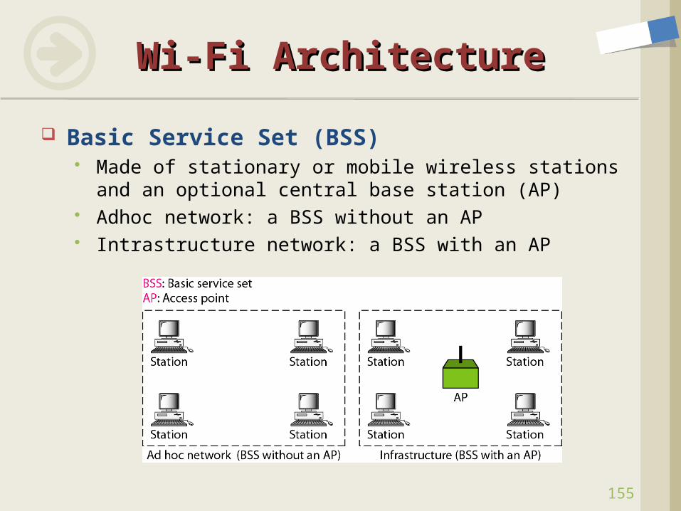
Wi-Fi ArchitectureWi-Fi Architecture
Basic Service Set (BSS) Made of stationary or mobile wireless stations and an
optional central base station (AP) Adhoc network: a BSS without an AP Intrastructure network: a BSS with an AP
156
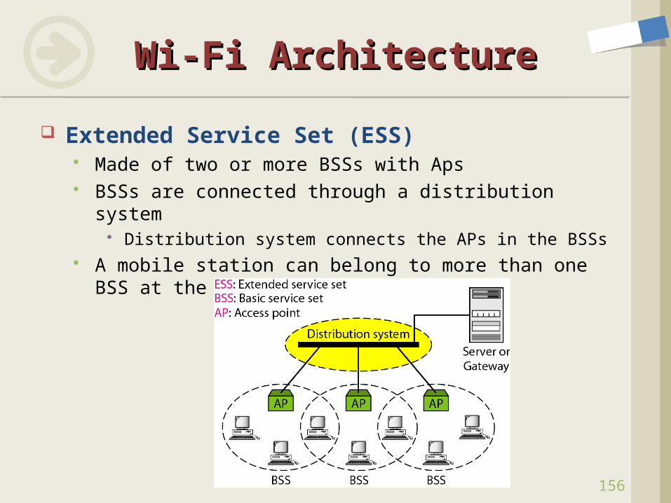
Wi-Fi ArchitectureWi-Fi Architecture
Extended Service Set (ESS) Made of two or more BSSs with Aps BSSs are connected through a distribution system
Distribution system connects the APs in the BSSs A mobile station can belong to more than one BSS at
the same time
157
Wi-Fi ArchitectureWi-Fi Architecture
Station Types Based on mobility
No-transition mobility Stationary : not moving Moving only inside a BSS
BSS-transition mobility Moving from one BSS to another inside one BSS Inter-BSS Handover
ESS-transition mobility Moving from one ESS to another Inter-ESS Handover
cf. Handover (Handoff) Issues Seamless HO, Smooth HO, Fast HO Soft HO, Hard HO Vertical HO
158
Wi-Fi Frame FormatWi-Fi Frame Format
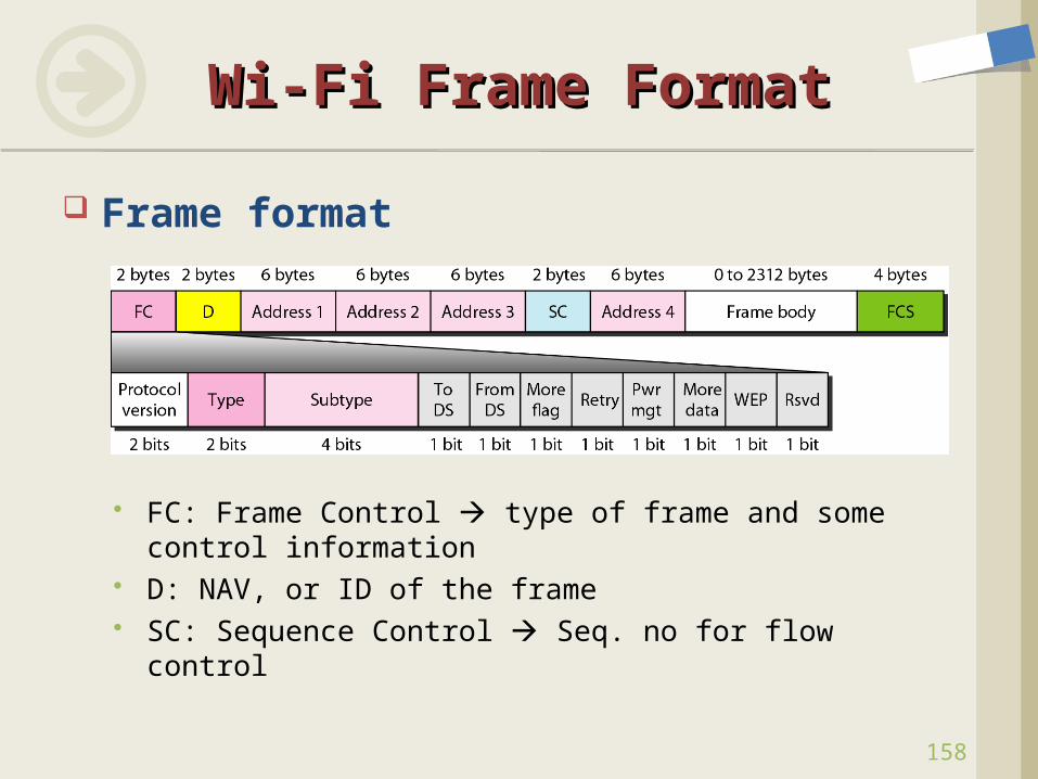
Frame format
FC: Frame Control type of frame and some control information
D: NAV, or ID of the frame SC: Sequence Control Seq. no for flow control
159
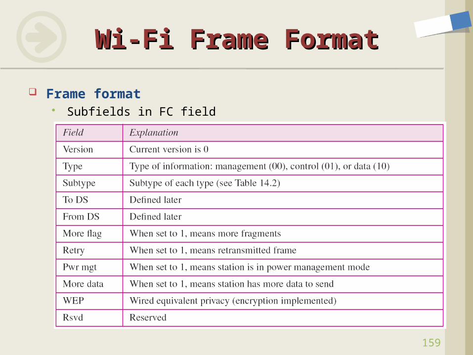
Wi-Fi Frame FormatWi-Fi Frame Format
Frame format Subfields in FC field
160
Wi-Fi Frame FormatWi-Fi Frame Format
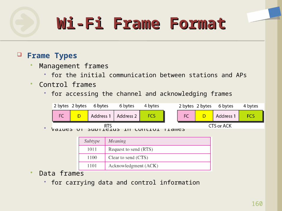
Frame Types Management frames
for the initial communication between stations and APs Control frames
for accessing the channel and acknowledging frames
values of subfields in control frames
Data frames for carrying data and control information
161
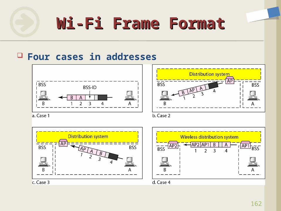
Wi-Fi Frame FormatWi-Fi Frame Format
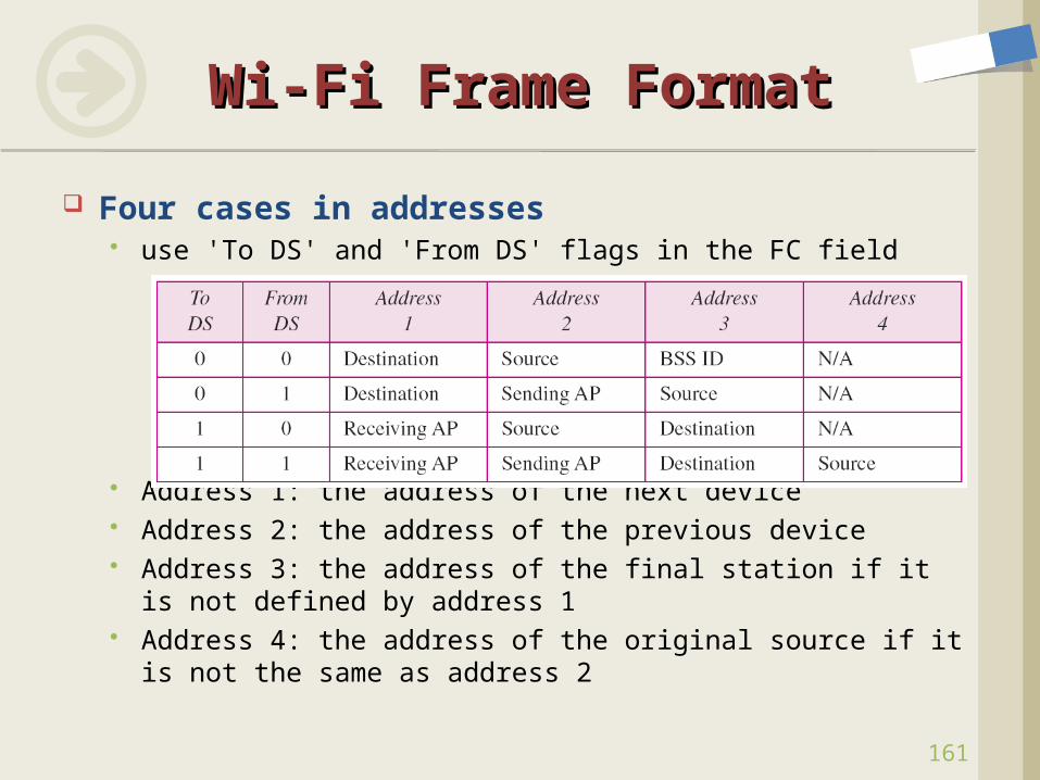
Four cases in addresses use 'To DS' and 'From DS' flags in the FC field
Address 1: the address of the next device Address 2: the address of the previous device Address 3: the address of the final station if it is not
defined by address 1 Address 4: the address of the original source if it is not
the same as address 2
162
Wi-Fi Frame FormatWi-Fi Frame Format
Four cases in addresses
Capture packets in Wireless LAN Check Wireless LAN technology Check the fields of WLAN frame
Non-security frame Security frame
Consider WLAN Security Issues Eavesdropping Hacking
Packet Capture with Packet Capture with WiresharkWireshark
163
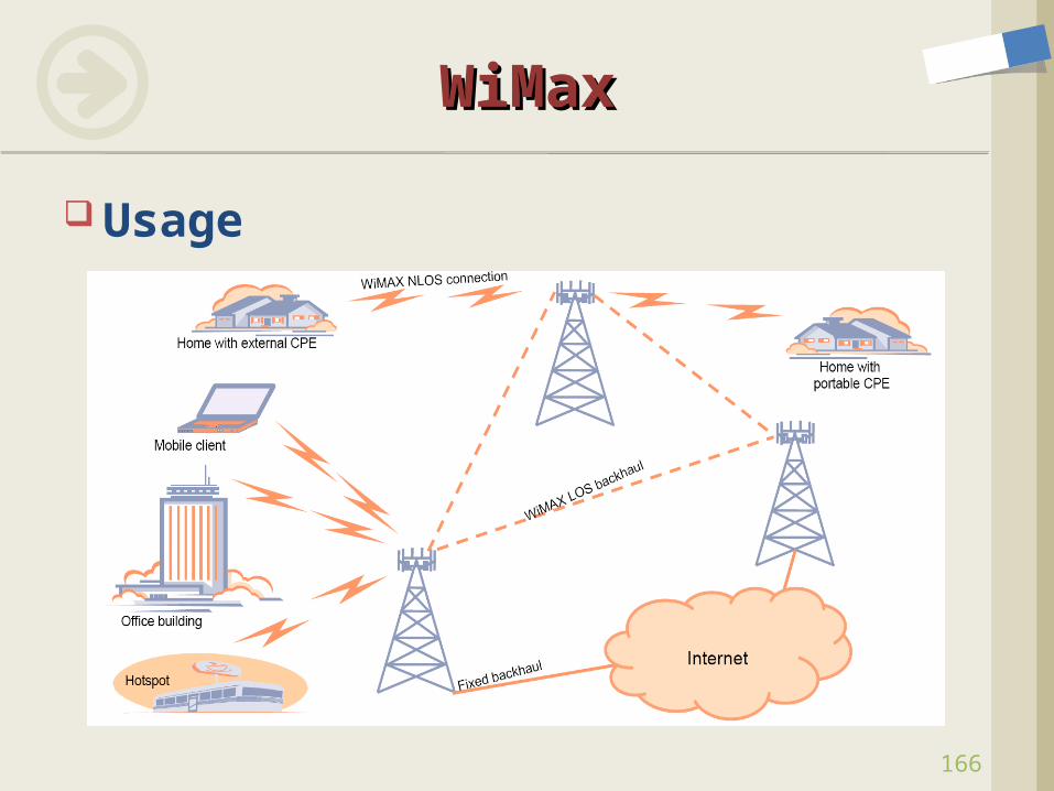
What is WiMax(Worldwide Interoperability for Microwave Access)? For the delivery of last mile wireless broadband access as
an alternative to cable and DSL. Provides fixed, nomadic, portable and, eventually, mobile
wireless broadband connectivity without the need for direct line-of-sight (LOS) with a base station.
In a typical cell radius deployment of three to ten kilometers, WiMAX Forum Certified™ systems can be expected to deliver capacity of up to 40 Mbps per channel, for fixed and portable access applications.
Mobile network deployments are expected to provide up to 15 Mbps of capacity within a typical cell radius deployment of up to three kilometers.
WiMaxWiMax
164
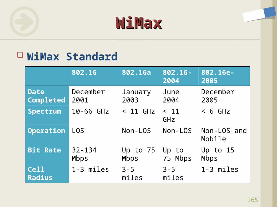
WiMax Standard
WiMaxWiMax
165
802.16 802.16a 802.16-2004
802.16e-2005
Date Completed
December 2001
January 2003
June 2004
December 2005
Spectrum 10-66 GHz < 11 GHz < 11 GHz
< 6 GHz
Operation
LOS Non-LOS Non-LOS Non-LOS and Mobile
Bit Rate 32-134 Mbps
Up to 75 Mbps
Up to 75 Mbps
Up to 15 Mbps
Cell Radius
1-3 miles 3-5 miles 3-5 miles 1-3 miles
Usage
WiMaxWiMax
166
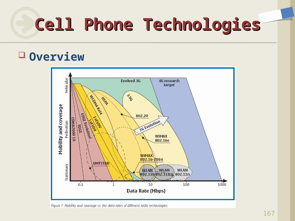
Overview
Cell Phone TechnologiesCell Phone Technologies
167
168
Cell Phone TechnologiesCell Phone Technologies
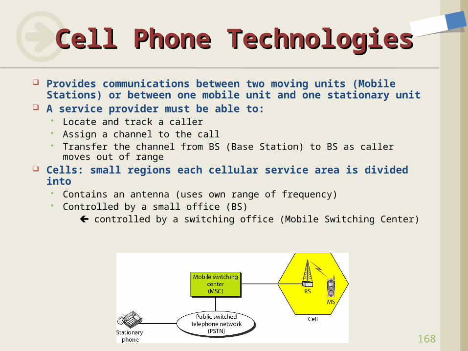
Provides communications between two moving units (Mobile Stations) or between one mobile unit and one stationary unit
A service provider must be able to: Locate and track a caller Assign a channel to the call Transfer the channel from BS (Base Station) to BS as caller moves out
of range Cells: small regions each cellular service area is divided
into Contains an antenna (uses own range of frequency) Controlled by a small office (BS) controlled by a switching office (Mobile Switching Center)
169
Cell Phone TechnologiesCell Phone Technologies
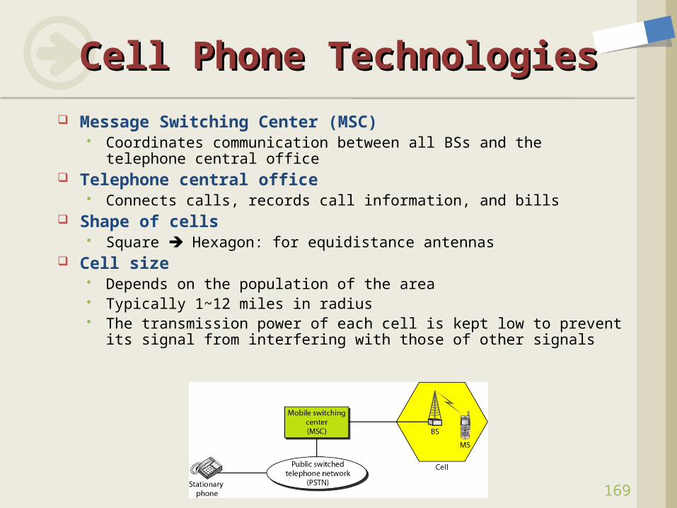
Message Switching Center (MSC) Coordinates communication between all BSs and the telephone
central office Telephone central office
Connects calls, records call information, and bills Shape of cells
Square Hexagon: for equidistance antennas Cell size
Depends on the population of the area Typically 1~12 miles in radius The transmission power of each cell is kept low to prevent its
signal from interfering with those of other signals
170
Cell Phone TechnologiesCell Phone Technologies
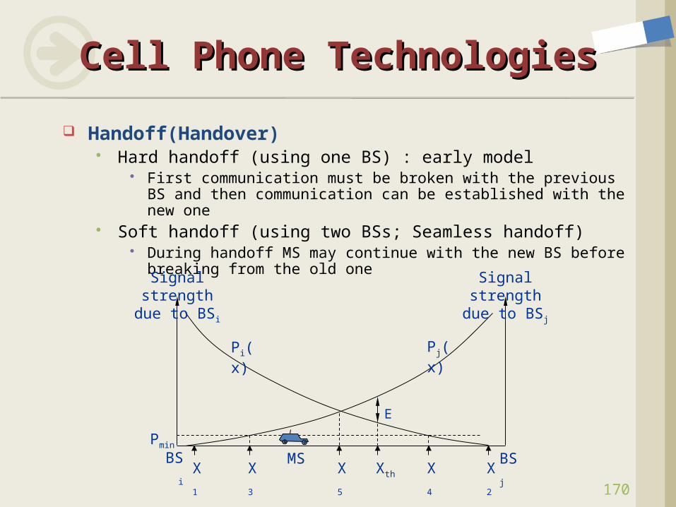
Handoff(Handover) Hard handoff (using one BS) : early model
First communication must be broken with the previous BS and then communication can be established with the new one
Soft handoff (using two BSs; Seamless handoff) During handoff MS may continue with the new BS before
breaking from the old one
BSi
Signal strength due
to BSj
E
X
1
Signal strength due
to BSi
BSjX
3
X
4
X
2
X
5
Xth
MSPmin
Pi(x)
Pj(x)
171
Cell Phone TechnologiesCell Phone Technologies
Roaming Problem A user can have access to
communication or can be reached where there is coverage
But a service provider usually has limited coverage
Solution approach: roaming Neighboring service providers can
provide extended coverage through a roaming contract
172
Cell Phone TechnologiesCell Phone Technologies
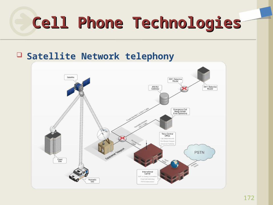
Satellite Network telephony
Exercises Calculate: 1, 3, 7, 19, 31, 32, 33, 34, 41, 43, 44, 47, 48 Analyze: 13, 24, 27, 28, 35, 52, 66
Experiments Wireshark experiments
Capture HTTP traffic from your PC with capture filter Screenshots: capture filter, captured traffic and information
5-Slide Survey Wireless mesh networks Motivation (why?), Problem (what?), Technique (how?)
Use PPT slides and upload at the Report board
Assignment #2Assignment #2
173