lecture 13 umts long term evolution - unipa.itilenia/course/13-lte-2013.pdf · release 99 (mar...
TRANSCRIPT

I. Tinnirello
Lecture 13
UMTS
Long Term Evolution

I. Tinnirello
Beyond 3G
� International Mobile Telecommunications (IMT)-2000
introduced global standard for 3G
� Systems beyond IMT-2000 (IMT-Advanced) are set to
introduce evolutionary path beyond 3G
� Mobile class targets 100 Mbps with high mobility and
nomadic/local area class targets 1 Gbps with low mobility
� 3GPP and 3GPP2 are currently developing
evolutionary/revolutionary systems beyond 3G
� 3GPP Long Term Evolution (LTE)
� 3GPP2 Ultra Mobile Broadband (UMB)
� IEEE 802.16-based WiMax is also evolving towards 4G
through 802.16m

I. Tinnirello
3GPP Evolution
�Release 99 (Mar 2000): UMTS/WCDMA
�Release-5 (Mar 2002): HSDPA
�Release-6 (Mar 2005): HSUPA
�Release-7 (2007): DL MIMO, IMS (IP Multimedia Subsystem), optimized realt time services (VoIP, gaming, push-to-talk)
�Long Term Evolution (LTE)
�3GPP work started in Nov 2004
�Standardized in the form of Release 8
�Spec finalized and approved in Jan 2008
�Target deployment starting from 2010
�LTE-Advanced study in progress

I. Tinnirello
IEEE 802.16 Evolution
�802.16 (2002): Line-of-isght fixed operation in 10 to 66 GHz
�802.16a (2003): Air interface support fro 2 to 11 GHz
�802.16d (2004): Minor improvements
�802.16e (2006): Support for vehicular mobility and asymmetrical links
�802.16m (2011): Higher data rate, reduced latency, efficient security mechanisms

I. Tinnirello
Requirements of LTE
� Peak data rate
� 100 Mbps DL/50 Mbps UP within 20 MHz bandwidth
� Up to 200 active users in a cell (5 MHz)
� Less than 5 ms user-plane latency
� Mobility
� Optimized for 0-15 Km/h
� 15-120 Km/h supported with high performance
� Supported up to 350 Km/h or even up to 500 Km/h
� Enhanced multimedia broadcast multicast service (E-MBMS)
� Spectrum flexibility: 1.25-20 MHz
� Enhanced support for end-to-end QoS

I. Tinnirello
LTE Enabling Technologies
�OFDM (Orthogonal Frequency Division Multiplexing)
�SC-FDMA (Single Carrier FDMA)
�MIMO (Multi-input Multi-output)
�Multicarrier channel-dependent resource scheduling
�Fractional frequency reuse

I. Tinnirello
LTE Enabling Technologies
�Single Carrier FDMA (SC-FDMA)
�A new multiple access technique which has similar
structure and performance to OFDMA
�Linearly pre-coded OFDMA
�Utilizes single carrier modulation and orthogonal frequency multiplexing using DFT-spreading in the transmitter and frequency domain equalization in the receiver
�Low PAPR respect to OFDMA
�H.G: Myung et al, “Single Carrier FDMA for Uplink wireless transmission”; IEEE Vehic. Tech.

I. Tinnirello
Key Features of LTE
� Multiple access scheme
� DL: OFDMA; UP: SC-FDMA
� Adaptive modulation and coding
� DL/UP modulations: QPSK, 16QAM and 64QAM
� Convolutional codes and Rel-6 turbo codes
� Advanced MIMO spational multiplexing techniques
� (2 or 4)x(2 or 4) downlink and uplink supported
� Multi-user MIMO
� TDD/FDD
� H-ARQ, mobility support, rate control, security, etc.

I. Tinnirello
Key Features of LTE

I. Tinnirello
Mobility Intra and Inter Technology
I. Tinnirello
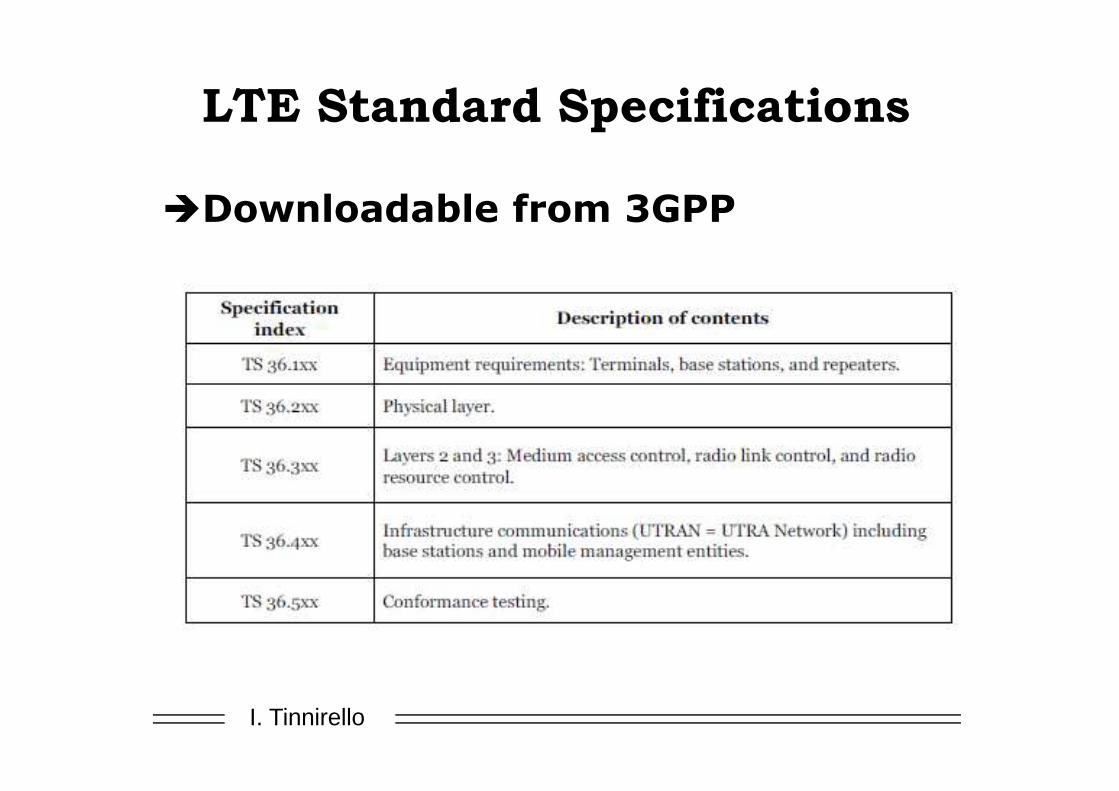
LTE Standard Specifications
�Downloadable from 3GPP

I. Tinnirello
Network and Protocol
Architecture

I. Tinnirello
Protocol Architecture

I. Tinnirello
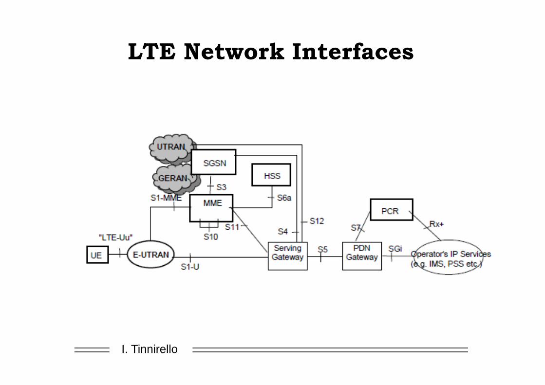
LTE Network Architecture
� E-UTRAN: Evolved Universal Terrestrial Radio Access Network

I. Tinnirello
LTE Network Architecture
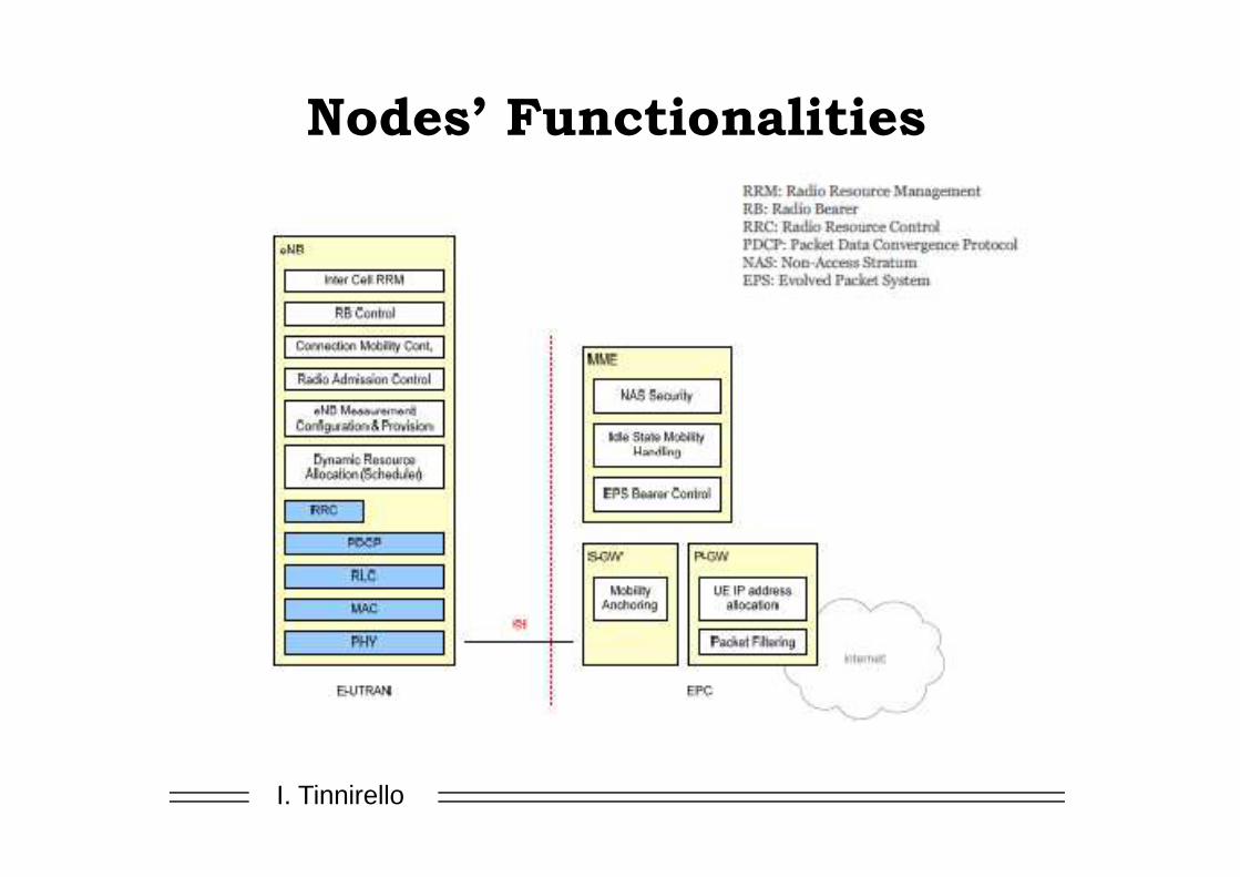
�eNB: enhanced Node B
�All radio interface-related functions
�MME: Management Mobility Entity
�Manages Mobility, UE identity and security parameters
�S-GW: Serving Gateway
�Node that terminates the interface towards E-UTRAN
�P-GW: Packet Data Network Gateway
�Node that terminates the interface towards PDN

I. Tinnirello
Novel Components
�The overall system architecture was revisited:�New Radio-Access Network (RAN)
�New Core Network (referred as EPC)
�The RAN is responsible of:�Scheduling and radio-resource handling
�Retransmission protocols
�Coding and antenna schemes
�The EPC is responsible of:�Authentication
�Charging functionality
�Connections setup
Evolved Packet System (EPS)

I. Tinnirello
Core Network
�The EPC is a radical evolution from the other core network (GSM/GPRS, WCDMA/HSPA)
�Supports access to the packet-switched domain only (no access to the circuit-switched domain)
�Contains several nodes:�Mobility Management Entity (MME)
�The Serving Gateway (S-GW)
�The Packet Data Network Gateway (PDN/P-GW)
�Other nodes:�Policy and Charging Rules Function
�Home Subscriber Service
�Multimedia Broadcast Multicast Services
�All this nodes are logical nodes!
I. Tinnirello
LTE Network Interfaces
I. Tinnirello
Nodes’ Functionalities

I. Tinnirello
Protocol Stacks

I. Tinnirello
Circuit-Switched Fall Back
(CSFB)
�LTE is a pure PS-switched network!
�natively supports VoIP using IMS services
�CSFB mechanism allows to handle voice calls by means of
3G/2G networks

I. Tinnirello
Message Sequence for CSFB

I. Tinnirello
Background on OFDMA
I. Tinnirello
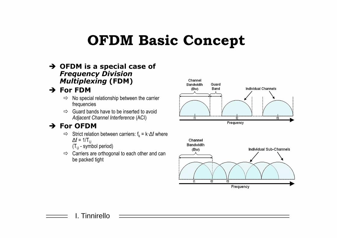
OFDM Basic Concept
� OFDM is a special case of Frequency Division Multiplexing (FDM)
� For FDM� No special relationship between the carrier
frequencies
� Guard bands have to be inserted to avoid Adjacent Channel Interference (ACI)
� For OFDM� Strict relation between carriers: fk = k·∆f where
∆f = 1/TU
(TU - symbol period)
� Carriers are orthogonal to each other and can be packed tight

I. Tinnirello
How does OFDM work?
�In principle similar to CDMA, with continous orthogonal codes!

I. Tinnirello
OFDM Transmission model
Channel, h(t)
Modulatorand transmitter
Wireless channel
Receiver and demodulator

I. Tinnirello
Orthogonality – the essential property
� Example: Receiver branch k
� Ideal channel: No noise and no multipath
Tu = 1/∆f gives subcarrier orthogonality over one Tu
=> possible to separate subcarriers in receiver
( )
≠=
==⋅
⋅ ∑ ∫∫ ∑
−
=
⋅−π∆π−
−
=
∆π
qk,0
qk,adte
T
adteea
T
1 k1N
0q
T
0
tT
1kq2j
U
qT
0
ftk2j1N
0q
ftq2jq
U
c U
U
U c
Received signal, r(t)
I. Tinnirello
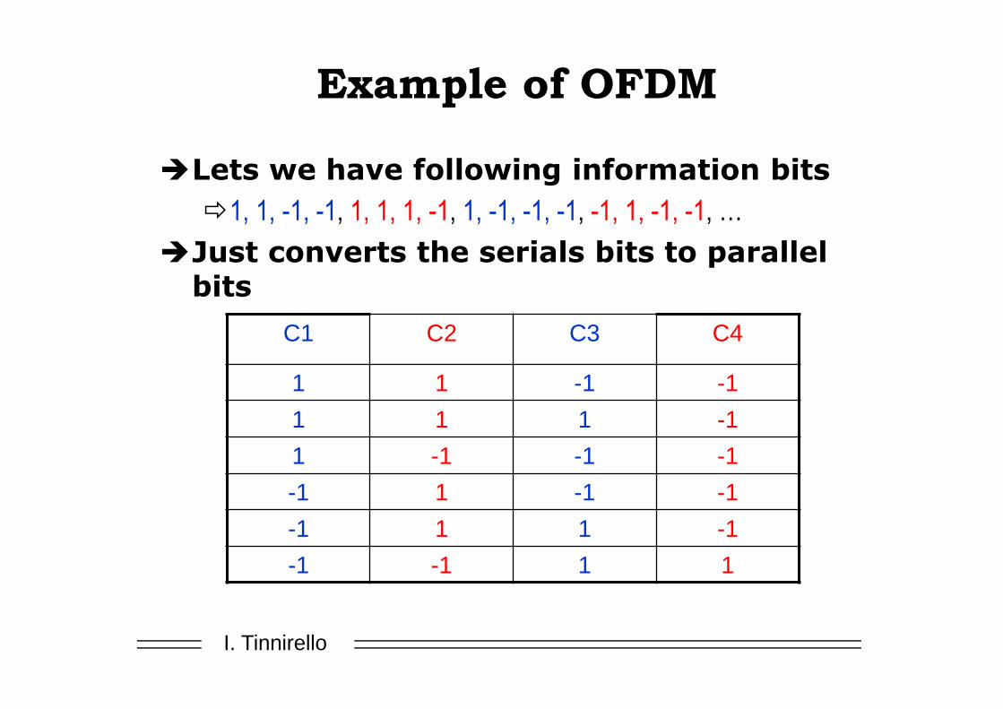
Example of OFDM
�Lets we have following information bits
�1, 1, -1, -1, 1, 1, 1, -1, 1, -1, -1, -1, -1, 1, -1, -1, …
�Just converts the serials bits to parallel bits
C1 C2 C3 C4
1 1 -1 -1
1 1 1 -1
1 -1 -1 -1
-1 1 -1 -1
-1 1 1 -1
-1 -1 1 1

I. Tinnirello
Example of OFDM cont..
Modulated signal for C1 Modulated signal for C2
Modulated signal for C3 Modulated signal for C4
Modulate each column with corresponding sub-carrier using BPSK

I. Tinnirello
Example of OFDM cont..
�Final OFDM Signal = Sum of all signal
)2sin()()(1
0nttItV
N
nn
π∑−
==
Generated OFDM signal, V(t)
V(t)

I. Tinnirello
Multipath channel
],[ 00 τα
],[ 11 τα
Diffracted and Scattered Paths
Reflected Path
LOS Path
],[ kk τα

I. Tinnirello
Multipath channel (cyclic prefix)
Time[τ]
Amplitude [α]
Example multipath profile
τ0 τ1 τ2 The prefix is made cyclic to avoid inter-carrier-interference (ICI) (maintain orthogonality)
Multipath introduces inter-symbol-interference (ISI)
TU
Prefix is added to avoid ISITUTCP

I. Tinnirello
Multipath channel (cyclic prefix)
� Tcp should cover the maximum length of the time dispersion
� Increasing Tcp implies increased overhead in power and bandwidth (Tcp/ TS)
� For large transmission distances there is a trade-off between power loss and time dispersion
CP Useful symbol CP Useful symbolCP Useful symbol
TUTcp
TS

I. Tinnirello
Multipath channel (frequency diversity)
=
• The OFDM symbol can be exposed to a frequency selective channel
• The attenuation for each subcarrier can be viewed as “flat”– Due to the cyclic prefix there is no need for a complex equalizer
• Possible transmission techniques– Forward error correction (FEC) over the frequency band– Adaptive coding and modulation per carrier

I. Tinnirello
Frequency/subcarrier
Pilot carriers /reference signalsData carriers
Multipath channel (pilot symbols)
� The channel parameters can be estimated based on known symbols (pilot symbols)
� The pilot symbols should have sufficient density to provide estimates with good quality (tradeoff with efficiency)
� Different estimation methods exist� Averaging combined with interpolation
� Minimum-mean square error (MMSE)
Pilot symbol
Time
Frequency

I. Tinnirello
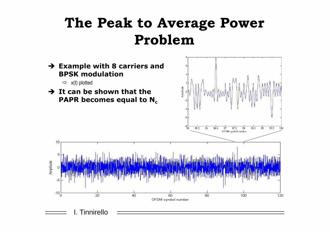
The Peak to Average Power
Problem� A OFDM signal consists of a number of independently
modulated symbols
� The sum of independently modulated subcarriers can have large amplitude variations
� Results in a large peak-to-average-power ratio (PAPR)
∑−
=
∆π⋅=1N
0k
tfk2jk
c
ea)t(x
PA
I. Tinnirello
The Peak to Average Power
Problem
� Example with 8 carriers and BPSK modulation � x(t) plotted
� It can be shown that the PAPR becomes equal to Nc

I. Tinnirello 38
The Peak to Average Power Problem
� High efficiency power amplifiers are desirable� For the handset, long battery life
� For the base station, reduced operating costs
� A large PAPR is negative for the power amplifier efficiency
� Non-linearity results in inter-modulation� Degrades BER performance
� Out-of-band radiation
PA
PIN
POUT
IBO
AM/AM characteristic
OBO
Average Peak

I. Tinnirello
The Peak to Average Power Problem
� Different tools to deal with large PAPR
� Signal distortion techniquesClipping and windowing introduces distortion and out-of-band radiation, tradeoff with respect to reduced backoff
� Coding techniquesFEC codes excludes OFDM symbols with a large PAPR (decreasing the PAPR decreases code space). Tone reservation, and pre-coding are other examples of coding techniques.
� Scrambling techniquesDifferent scrambling sequences are applied, and the one resulting in the smallest PAPR is chosen

I. Tinnirello
Summary
� Advantages
� Splitting the channel into narrowband channels enables significant simplification
of equalizer design
� Effective implementation possible by applying FFT
� Flexible bandwidths enabled through scalable number of sub-channels
� Possible to exploit both time and frequency domain variations (time domain
adaptation/coding + freq. domain adaptation/coding)
� Challenges
� Large peak to average power ratio

I. Tinnirello
Radio Interface

I. Tinnirello
Frame Structure
�Two radio frame structures
�Type 1: FS1 FDD
�Type 2: FS2 TDD
�A radio frame has a duration of 10 ms
�A resource block (RB) spans 12 subcarriers over a slot duration of 0.5ms
�One subcarrier has a 15 KHz bandwidth, thus 180
KHz per RB

I. Tinnirello
Frame Structures
�FDD
�TDD

I. Tinnirello
Resource Grid

I. Tinnirello
LTE Bandwidth/Resource
Configuration

I. Tinnirello
Bandwidth Configuration
Example

I. Tinnirello
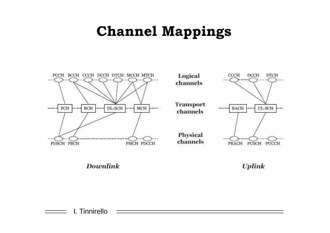
LTE Physical Channels
� A set of subcarriers lasting some symbols
� DL:
� Physical Broadcast Channel (PBCH)
� Physical Control Format Indicator Channel (PCFICH)
� Physical Downlink Control Channel (PDCCH)
� Physical Hybrid ARQ Indicator Channel (PHICH)
� Physical Downlink Shared Channel (PDSCH)
� Physical Multicast Channel (PMCH)
� UP:
� Physical Uplink Control Channel (PUCCH)
� Physical Uplink Shared Channel (PUSCH)
� Physical Random Access Channel (PRACH)

I. Tinnirello
LTE Transport Channels
�DL:
�Broadcast Channel (BCH)
�Downlink Shared Channel (DL-SCH)
�Paging Channel (PCH)
�Multicast Channel (MCH)
�UP:
�Uplink Shared Channel (UL-SCH)
�Random Access Channel (RACH)
I. Tinnirello
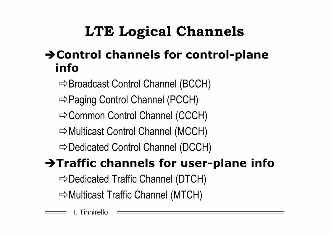
LTE Logical Channels
�Control channels for control-plane info
�Broadcast Control Channel (BCCH)
�Paging Control Channel (PCCH)
�Common Control Channel (CCCH)
�Multicast Control Channel (MCCH)
�Dedicated Control Channel (DCCH)
�Traffic channels for user-plane info
�Dedicated Traffic Channel (DTCH)
�Multicast Traffic Channel (MTCH)
I. Tinnirello
Channel Mappings

I. Tinnirello
LTE Layer 2

I. Tinnirello
RRC Layer
�Terminated in eNB on the network side
�Broadcast, Paging
�RRC connection management
�Radio Bearer management
�Mobility Functions
�UE measurement reporting and control
�RRC states:
�RRC_IDLE, RRC_CONNECTED

I. Tinnirello
Resource Scheduling of Shared
Channels
�Dynamic resource scheduler resides in eNB on MAC layer
�Radio resource assignment based on radio condition, traffic volume and QoS requirements
�Radio resource assignment consists of:
�Physical Resource Block (PRB)
�Modulation and Coding Scheme (MCS)

I. Tinnirello
Radio Resource Management
�Radio Bearer Control (RBC)
�Radio Admission Control (RAC)
�Connection mobility Control (CMC)
�Dynamic resource allocation (DRA) or packet scheduling
�Inter-cell interference coordination (ICIC)
�Load Balancing (LB)
�Other: ARQ, H-ARQ, Rate Control, DRX, QoS, Scurity
I. Tinnirello
LTE Uplink

I. Tinnirello
UL Resource BLock
I. Tinnirello
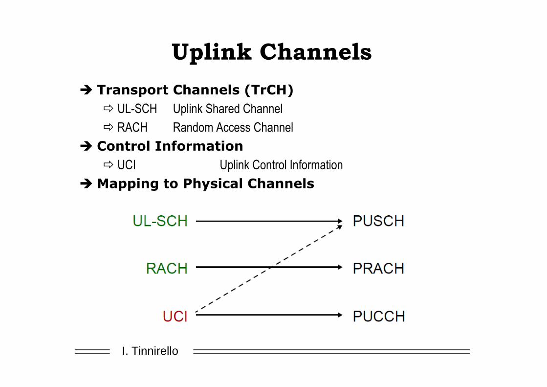
Uplink Channels
� Transport Channels (TrCH)
� UL-SCH Uplink Shared Channel
� RACH Random Access Channel
� Control Information
� UCI Uplink Control Information
� Mapping to Physical Channels

I. Tinnirello
Uplink Control Signalling
�Conveys L1 and L2 control information
�HARQ acknowledhements for DL-SCH blocks
�Channel quality reports: CQI, RI and PMI
�Scheduling requests
�Transmitted on
�PUCCH if no resources are allocated to UL-SCH
�Multiplexed with UL-SCH on the PUSCH (before
SC_FDMA) if there is a valid schedule grant

I. Tinnirello
Data and Control Information on PUSCH

I. Tinnirello
Channels and Signals
� A physical channel is defined as a set of resource elements carrying information originating at a higher layer or in support to the physical layer itself
� For the uplink, the following PHY channels are defined..
� PUSCH: Phy Uplink Shared Channel
� PUCCH: Phy Uplink Control Channel;
� PRACH: Phy Random Access Channel
� ..plus the following signals
� Souding Reference Signal (SRS)
�Not associated with any other transmission
� Demodulation Reference Signal (DRS)
�associated with PUSCH or PUCCH, for channel estimation
�Desired features: small power variations in time and frequency

I. Tinnirello
Sounding Reference Signal
� eNodeB needs channel quality information in order to assign resources
� From DRS eNobeB can only get channel estimates on UE allocated spectrum
� No information available out of assigned spectrum
� SRS overcomes this problem!

I. Tinnirello
Sounding Reference Signal (2)
� May cover large frequency span (not assigned to UE)
� Multiple of 4 resource blocks span
� Can be transmitted from every 2ms to every 160ms
� Transmitted on last symbol of subframe (at most every 2 subframes)
� Multiple UEs can transmit simultaneously thanks to cyclic shifts (orth codes)� Wideband: one transmission covers band of interest
� Frequency hopping: narrowband, location changes with time

I. Tinnirello
Physical Uplink Control Channel
�PUCCH:
�Conveys uplink control information
�Used when UE has no valid schedule grant
�Never transmitted simulanteously with PUSCH
�Transmitted with frequency hopping on band edges to leave contiguos bandwidth to PUSCH
�Multiple PUCCH over a RB by means of orthogonal codes

I. Tinnirello
Physical Uplink Shared Channel
� PUSCH:
� Carries data and control information, by means of the following
processing chain
� Allocated spectrum to a UE can changge every subframe

I. Tinnirello
SC-FDMA Modulation in LTE UP

I. Tinnirello
Uplink Summary

I. Tinnirello
LTE Downlink

I. Tinnirello
Downlink Channels
� Transport Channels (TrCH)
� DL-SCH Downlink Shared Channel
� BCH Broadcast Channel
� PCH Paging Channel
� MCH Multicast Channel
� Control Information
� CFI Control Format Indicator
� HI HARQ Indicator
� DCI Downlink Control Information
� Mapping to Phy Channels

I. Tinnirello
Downlink Channels and Signals
� Phy Channel: set of resource elements carrying information from higher layers
� Phy DL Shared Ch PDSCH; Phy DL Control CH PDCCH; Phy Multicast
Ch PMCH; Phy Broadcast Channel PBCG; Phy Control Format Indicator
Channel PCFIC; Phy HARQ Indicator Channel PHICH
� Phy Signal: set of resource elements used for physical layer information
� Reference Signals
� Synchronization Signals

I. Tinnirello
Phy Donwlink Channels
�PCFICH: Specifies how many OFDM symbols are used for PDCCH transmission
�PDCCH: carries control information including scheduling assignments;
�PHICH: hybrid ARW and NACK indicators for Ues
�PDSCH: main downlink channel to transport data blocks to the mobiles
�PBCH: broadcast information with a coded block of 1920 samples every 40 ms

I. Tinnirello
Donwlink Reference Signals
�Used for channel estimations and to obtain quality measurements at the UE side
�Cell-specific:
�Structure depends on the cell ID
�UE- specific
�Used for beamforming
�Arranged across time and frequency

I. Tinnirello
DL Reference Signal

I. Tinnirello
Synchronization Signals
�Always transmitted in the same place regardless of the total bandwidth
�First 72 carriers around DC carrier
�OFDM symbols 5 and 6 of first slot in subframe 0 and 5

I. Tinnirello
Downlink Processing Chain
�The general structure of downlink physical channels processing is the following one (for PDSCHs)
I. Tinnirello
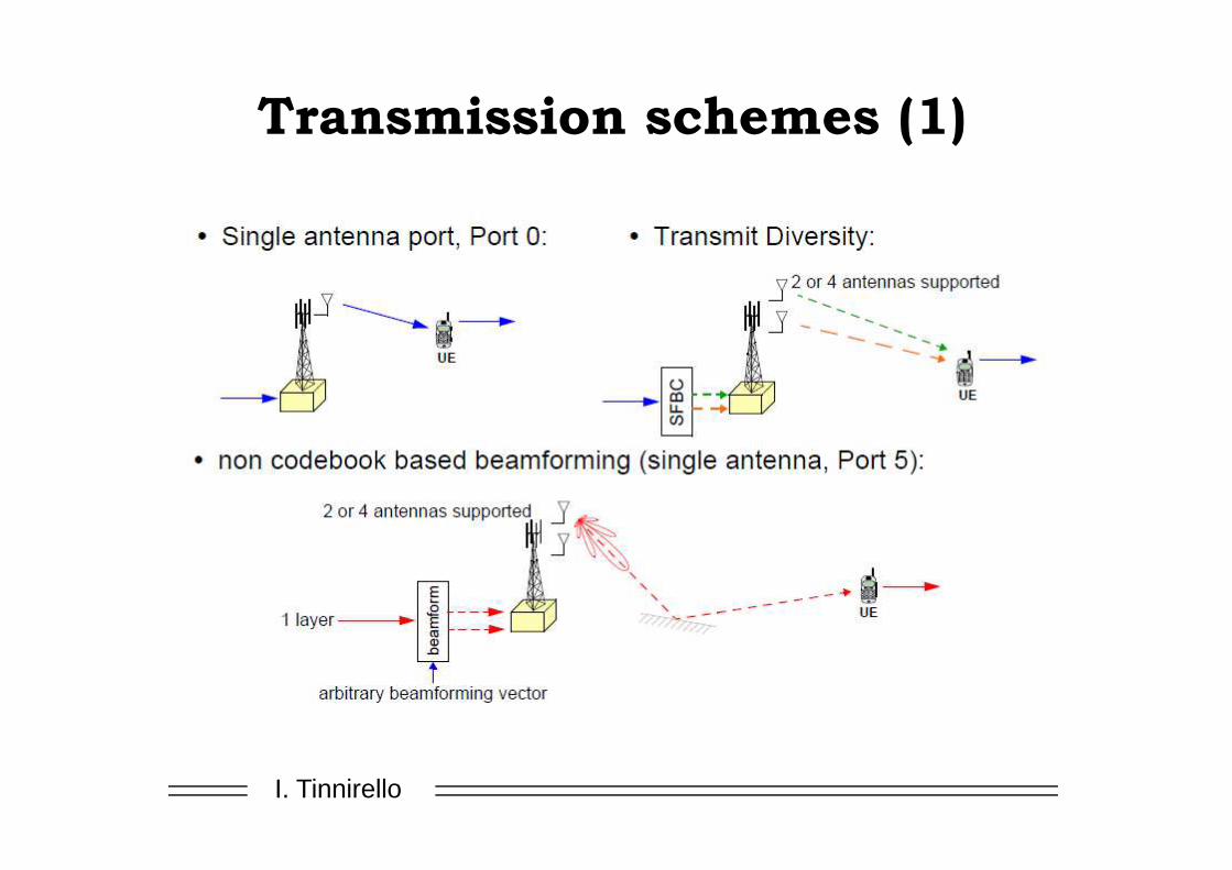
Transmission schemes (1)

I. Tinnirello
Transmission Schemes (2)

I. Tinnirello
Transmission Schemes (3)

I. Tinnirello
Downlink Summary
I. Tinnirello
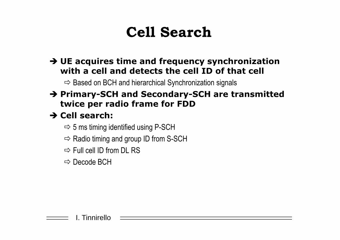
Cell Search
� UE acquires time and frequency synchronization with a cell and detects the cell ID of that cell
� Based on BCH and hierarchical Synchronization signals
� Primary-SCH and Secondary-SCH are transmitted twice per radio frame for FDD
� Cell search:
� 5 ms timing identified using P-SCH
� Radio timing and group ID from S-SCH
� Full cell ID from DL RS
� Decode BCH

I. Tinnirello
Random Access
�Open loop power controlled with power ramping
�RACH signal bandwidth: 1.08 MHz (6RBs)

I. Tinnirello
LTE Release 10 and beyond
�Carrier aggregation to give up to 100MHz bandwidth
�Downlink transmission with 8 antennas and layers
�Uplink multi-antenna up to 4 antennas
�Coordinated Multi Point transmission
�Relaying from Relay Nodes to eNB
�Latency Improvements
�Self Optimising Networks enhancements
�Home eNobeB (femtocells)