leak detection and repair ldar
TRANSCRIPT
LEAK DETECTION AND REPAIR
LDAR
TECHNICAL RECOMMENDATIONS BASED ON BEST PRACTICES APPLIED BY EUROPEAN GAS SYSTEM
OPERATORS
April 2021

1
Contact
MARCOGAZ AISBL
Rue Belliard, 40
1040 Brussels - Belgium
www.marcogaz.org
ABOUT MARCOGAZ
Founded in 1968, Marcogaz represents 29 member organisations from 20 countries. Its mission encompasses monitoring and policy advisory activities related to the European technical regulation, standardisation and certification with respect to safety and integrity of gas systems and equipment, rational use of energy as well as environment, health and safety issues. It is registered in Brussels under number BE0877 785 464.
DISCLAIMER
This document and the material herein are provided “as is”. All reasonable precautions have been taken by MARCOGAZ to verify the reliability of the content in this document. However, neither MARCOGAZ nor any of its officials, agents, data or other third-party content providers provides a warranty of any kind, either expressed or implied, and they accept no responsibility or liability for any consequence of use of the document or material herein.
The information contained herein does not necessarily represent the views of all Members of MARCOGAZ. The mention of specific companies or certain projects or products does not imply that they are endorsed or recommended by MARCOGAZ in preference to others of a similar nature that are not mentioned. The designations employed, and the presentation of material herein, do not imply the expression of any opinion on the part of MARCOGAZ concerning the legal status of any region, country, territory, city or area or of its authorities, or concerning the delimitation of frontiers or boundaries.

2
CONTENT
I. Introduction .............................................................................................. 4 II. General information on LDAR programmes ............................................... 4
Preparation & improvement ........................................................................... 5 On-site surveys ........................................................................................... 6 Leak repairs & monitoring ............................................................................. 6 Reporting & data analysis .............................................................................. 6
III. LDAR programmes in the above ground installations of gas transmission networks, LNG terminals and UGS ...................................................................... 7
Preparation & improvement ........................................................................... 7 On-site surveys ........................................................................................... 8 Leak repairs & monitoring ........................................................................... 10 Reporting & data analysis ............................................................................ 11
IV. LDAR programmes in gas distribution networks ..................................... 11 Preparation & improvement ......................................................................... 11 On-site surveys ......................................................................................... 12 Leak repairs & monitoring ........................................................................... 13 Reporting & data analysis ............................................................................ 13
V. Closing remarks ...................................................................................... 14 VI. References .............................................................................................. 15 Annex I – Repair cases and strategies ............................................................. 16
Simple case ............................................................................................... 16 Intermediate complexity case ...................................................................... 17 Complex case ............................................................................................ 18 Typical repair strategy for DSO .................................................................... 20
Annex II – LDAR survey performed by GIE and MARCOGAZ ............................. 22 Slides 1-24 (23/12/2020) ........................................................................... 22 Remaining slides (21/01/2021) .................................................................... 33
LIST OF FIGURES
Figure 1 - Process for LDAR programmes ................................................................. 5 Figure 2 - Example of exercise of detection of leak at above ground asset. ................... 9 Figure 3 - Example of emission quantification at above ground asset. ........................ 10 Figure 4 - Example of leak detection with car driving along buried lines. .................... 12 Figure 5 – Illustration of a leak to be repaired – simple case. .................................... 16

3
Figure 6 - Simple case – Simplified P&ID ................................................................ 16 Figure 7 – Illustration of a leak to be repaired – intermediate complexity case. ........... 17 Figure 8 - Intermediate complexity case – Simplified P&ID ....................................... 17 Figure 9 – Illustration of a leak to be repaired – complex case. ................................. 18 Figure 10 – Complex case – Simplified P&ID ........................................................... 18 Figure 11 – Dutch standard for leak survey (NEN 7244-6) ........................................ 20 Figure 12 – Illustration of walking detection via carpet probe .................................... 20 Figure 13 – Carpet probe / methane detector ......................................................... 21

4
I. Introduction
In a global context where decarbonisation of the energy systems is crucial for accelerating the energy transition and contribute to the European objective to reach climate neutrality by 2050, methane (CH4) emissions have an important impact and need to be mitigated.
On the 14th of October 2020, the European Commission published the Communication1 on an “EU strategy to reduce methane emissions”. The Strategy states that a legislative process will be conducted and new regulations will be delivered in 2021. The Commission calls on companies to set up more robust leak detection and repair (LDAR) programmes to be prepared for legislation that would make such programmes mandatory.
Methane emissions management and reduction is among the European gas industry top priorities and operators remain more than ever committed to deliver EU Green Deals’ objectives. As part of its methane emissions mitigation strategy, gas companies conduct LDAR programmes on regular basis.
MARCOGAZ developed this recommendation document on LDAR programmes for the gas midstream (above ground2 installations of transmission networks, LNG regasification terminals and underground gas storages) and downstream (distribution networks) segments taking into consideration the best practices applied by European gas system operators. Annex II shows the current status and practice of the European gas infrastructure concerning LDAR, this should be considered for future developments.
The recommendations are intended to be used as a technical guide to improve the results of the programme for companies that have not thoroughly applied LDAR programmes yet.
II. General information on LDAR programmes
For several decades, gas system operators have been routinely conducting detection and mitigation of methane emissions, not only as a safety requirement but also for environmental reasons. The LDAR programme is part of the core business of a gas system operator and the good execution of this activity remains under his reponsibility, even if he decides to delegate the operational tasks to a third party. A wide literature of best practices to mitigate methane emissions is already available for the gas industry [1].
Periodic LDAR programmes contribute to effectively reduce methane emissions from operated assets. LDAR is a programme to identify and repair the equipment or infrastructure that can be a source of emissions due to tightness failure. While LDAR in certain jurisdictions can have a specific regulatory definition, it is more generally used to
1 COM(2020) 663 final – Communication from the Commission on an EU strategy to reduce methane emissions https://ec.europa.eu/commission/presscorner/detail/en/ip_20_1833 2 Some gas system elements (f.i. valves) are located underground but with access without digging and are therefore included in the scope.

5
describe the processes and systems by which leaking equipment is identified, prioritized and then repaired.
The LDAR programme involves the comprehensive scanning of individual equipment and components to detect leaks and repair them. These activities may also give a good opportunity to quantify the emissions of certain types of assets.
A typical LDAR programme follows four different stages comprising preparation which is the first phase of the process, followed by on-site surveys and if leak is detected, it is followed by leak repairs and maintenance and the last is reporting and data analysis. Figure 1 depicts the LDAR process:
Figure 1 - Process for LDAR programmes
The four different stages of LDAR, identified as being the best practices for most gas operators are briefly described in the following sessions:
Preparation & improvement
Each LDAR campaign requires a detailed preparation phase to ensure high level performances. At least the following tasks have to be executed prior to the on-site surveys:
• Define leaks and leak criteria for repair and quantification:
o Classify the leaks considering the specific threshold limit value (may be set differently for individual elements), and/or
o Classify other considerations, such as the surrounding of the leak.
• Identify all the potential emission sources (e.g. valves) taking into account the characteristics of the asset. This information needs to be recorded.

6
• Plan the process comprising schedule, resources and organisation of the field activities. The planning of LDAR survey and quantification activities can be by fixed overall schedule or can be condition based. MARCOGAZ recommends a condition based approach as this recognizes the wide variety of asset conditions that exists and enables smart optimization. Transparency of the approach should be assured by clearly documented critera and considerations.
• Select the technologies/instruments to detect, measure and/or quantify methane emissions.
The Methane Guiding Principles Best Practice Guide on identification, detection, measurement and quantification of methane emissions [2] contains a detailed description on the current and emerging technologies (main use, level of confidence, accuracy, advantages and disadvantages, …).
On-site surveys
• On-site detection of methane leaks.
• In some cases, simultaneous on-site detection of leaks and on-site measurements.
• Record the location of emission source in case a repair cannot be executed immediately.
• Record all the obtained results.
Leak repairs & monitoring
• Confirm the origin of the leaks (e.g. separating it from biogenic methane emissions).
• Immediate repair of leaking components wherever possible or otherwise classify the leaks.
• Prioritise the repairs according to the classification and set up a monitor and repair plan.
• After the leak is repaired, it is recommended to verify the effectiveness of the repair (mainly done for larger leaks).
Reporting & data analysis
MARCOGAZ recommends that the report on the methane emission contains an explanation of the gas system considered, a description of asset division into groups and methane emission types, documentation on which emission factors have been based, and information of own emission factors and their uncertainty.
For each leak, it is recommended to record the obtained results:
• Reference of the instruments used if relevant,

7
• Location/identification of the leaking component,
• Measurements when needed for quantification,
• Date when the leak was detected,
• Date when the leak was repaired,
• Results of monitoring tests to determine if the repair was successful if suitable (i.e. systematic periodic detection performed every year),
As more information is recorded per source, more accurate analysis of the leakage behavior can be performed.
To ensure effective use of information, relevance, completeness, consistency and transparency are key principles for analysing and reporting on emission.
The above described stages are considered as the generic ways followed to perform the LDAR programme. However, depending on the circumstances or peculiarity of the pre-defined criteria, the operators may consider different and additional phases.
Technical recommendations, LDAR protocols, personnel training requirements, and reporting and repair procedures should be available to ensure that the company has set up robust LDAR programmes.
LDAR programmes for the gas midstream and downstream segments have in common the four above-mentioned stages but due to the distinctive specificities of above ground installations of transmission networks, LNG regasification terminals, underground gas storages and the distribution networks, the following section III and section IV present respectivelly these different approaches in detail.
III. LDAR programmes in the above ground installations of gas transmission networks, LNG terminals and UGS
Preparation & improvement
Leak threshold
A leak is considered to be assessed or quantified if it exceeds a certain threshold limit value (e.g. concentration or flow rate) as defined in the preparation phase.
MARCOGAZ recognizes that operator’s practices are different and that a common threshold is not existing at the moment.
Identification
The identification of all potentially leaking components (valves, connectors, blow-down open-ended lines, flanges, control valves, pressure relief valves, pumps) at LNG terminals, underground gas storages and the above ground installations of the

8
gas transmission network (i.e. compressor stations, regulating / reduction / metering stations, valve stations, measurement stations, gas delivery station) is performed based on the technical documentation of the asset (P&IDs, process diagrams, parameters).
Leak detection, measurement and/or quantification instruments
The following instruments3 can be eligible to detect, measure and/or quantify leaks depending on the purpose, the characteristics of the asset and the cost-effectiveness:
• Soap spray;
• Portable leak detectors (such as flame ionisation detectors (FID) or semiconductor sensors);
• Fixed detectors (to monitor in real-time the methane concentration),
• Bagging;
• Portable mass flow detectors (such as hi flow sampler);
• Mass flow meters;
• Optical gas imaging (OGI);
• Other proven techniques (i.e. volume and pressure drop measurements).
Detection limits for the instruments may vary over a large range.
On-site surveys
Detection
A robust identification programme is established for the above ground installations of gas transmission grids, compressor stations, LNG terminals and UGS. The devices of these assets must be inspected to detect leaks by means of the leak detection instrument selected.
3 MGPs Best Practice Guide Identification, Detection, Measurement and Quantification [2] and the MARCOGAZ’ Assessment of methane emissions for Gas Transmission & Distribution System Operators [3].

9
Figure 2 - Example of exercise of detection of leak at above ground asset. Source: MARCOGAZ’ members
Frequency of the inspection (detection)
The frequency of the inspections is set in some countries through the national regulation and/or technical standards (mainly for safety reasons) or by the operators (for both safety and environmental reasons) while in other countries there may not be a pre-defined frequency for inspection.
MARCOGAZ recommends that assets are periodically inspected. Companies should set the inspection frequency based on the results of previous campaigns. At least for the relevant assets, initial inpections should be performed on an annual basis.
These inspections can be carried out with soap spray, portable leak detectors or OGI, but other instruments may be used as well.
Quantification
In addition to the previous steps, quantification of emission can be done using measurements (concentration or mass flow4) and appropriate correlation equation or by direct quantification according to the instrument used.
Correlation factors are used to estimate emission rates of every identified leak and annual emission rates considering the detection/measurement dates and repair dates. The correlation factors are based on the factors published in the European standard EN 154465, SOCMI correlations (developed for Chemical Industry) and EPA Petroleum Industry correlation. As there are significant differences in the quantification of emissions, the equation of correlation is different.
MARCOGAZ recommends to further develop and harmonise specific correlation factors for the gas industry.
4 For bigger leaks, mass flow measurements are proven to be more accurate, but more time consuming. 5 EN 15446: “Fugitive and diffuse emissions of common concern to industry sectors - Measurement of fugitive emission of vapours generating from equipment and piping leaks”.

10
Figure 3 - Example of emission quantification at above ground asset. Source: MARCOGAZ’ members
In case of direct quantification measurements (e.g. Hi Flow, mass flow) the annual emission rates are directly recorded.
A representative sample of components and equipment can be used to define specific emissions factors.
Frequency of measurements/quantification
Based on the current and best practices at European level, MARCOGAZ recommends:
• For the above ground installations of gas transmission grids, compressor stations, LNG terminals and UGS, methane emissions should be measured/quantified every 4-years.
• For less complex transmission assets (e.g. grid valve stations, R&R stations), the recommendation is to measure a representative sample of these assets every 4-years and to extrapolate the results for the quantification of the total installation emissions.
Leak repairs & monitoring
Repairs
The detected leaks needs to be repaired as soon as possible taking into account safety, technical and economic aspects.
Immediate repair can be understood as the repair done during the routine maintenance carried out just following the detection campain, having both activity synchronized allow to repair quickly most of the leak in safe conditions (e.g.

11
replacement of seals, greasing and/or quick adjustments). The responsible for the LDAR programme assesses whether the reparation is feasible at that moment (parallel repair).
Leaks that cannot be directly repaired are classified. The classification of the leaks takes into consideration the safety and environmental impact, the amount of methane, the concentration of the leak, the accessibility, and the cost-effectiveness.
For those leaks that cannot be repaired directly, monitoring is recommended.
Period for planned repairs - Prioritisation
Based on the classification of the leaks, prioritisation and a planning of the repairs are included in the maintenance plan.
MARCOGAZ recommends to carry out the repairs within 1 year from detection considering its safety impact, the environmental aspects and its cost-effectiveness. Some specific situations need to solved via dedicated procedures with possibiliy to deviate from the 1 year recommendation. (See annex I)
After each repair, it is recommended to remeasure the leak and check the result of the repair (mainly done for larger leaks) and to carry out periodic controls.
Reporting & data analysis
The recommendation on the information to be recorded in the inventory is in line with the above general information.
The results and data should be analysed to improve the process.
IV. LDAR programmes in gas distribution networks
Preparation & improvement
Leak threshold
A leak is considered to be assessed or quantified if it exceeds a certain threshold limit value (e.g. concentration) as defined in the preparation phase. (See §VI.4).
MARCOGAZ recognizes that operator’s practices are different and that a common threshold is not existing at the moment.
Identification
The identification of potentially leaking components and equipment of the gas distribution network, including all above ground installations (i.e. pressure

12
regulating stations, metering stations, city gate stations) is performed based on the technical documentation of the asset (P&IDs, process diagrams, parameters).
Leak detection and/or measurement instruments
Leak survey of distribution systems can be done using different platforms (e.g. Walking with carpet probe, or car driving along buried lines). Sensors should be suitable for the way that they are used. Possible sensor types are flame ionisation, or semiconductor devices, laser-based absorption or spectroscopic (cavity ring down). Other proven techniques (e.g. soap bubble screening, volume and pressure drop measurements …) may also be used. Attention must be paid to the probability of false positive and non-detection, specific to the sensors and methods used.
See §VI.4 for a specific example.
Figure 4 - Example of leak detection with car driving along buried lines. Source: MARCOGAZ’ members
On-site surveys
Detection
The components of the gas distribution network must be inspected for the release of gas by means of an suitable leak detection instrument.
Frequency of the inspection
The frequency of inspections is set in some countries through the national regulation and/or technical standards (mainly for safety reasons) or by the operator (for safety and environmental reasons). Apart from these regulations and/or standards, the distribution grid operator may determine the frequency of the inspection based on parameters such as:

13
• Type of device or component;
• Operating pressure;
• Material’s properties;
• Age of the device or component;
• Results of previous LDAR campaign;
• Additional risk assessments (generally according to EN 12007-1).
Quantification
Specific emission factors (depending on the material of the pipes) can be used to estimate emission rates of every identified leak and annual emission rates taking into account the detection/measurement dates and repair dates. Activity factors (number of leaks) are derived from survey activities.
Leak repairs & monitoring
Repairs
The detected leaks needs to be repaired as soon as possible taking into account safety, technical and economic aspects. Immediate repairs are those carried out during the campaign, at the same time of detection (e.g. retightening, seal replacement and/or adjustments). The person responsible for detecting and measuring assesses whether the repair is feasible at the same moment (instant repair). If so, that person will initiate the appropriate repair procedure.
Repairs that cannot be performed immediately are planned and they need to be classified taking into consideration different aspects such as safety impact, amount of methane, concentration of the leak, accessibility, cost-effectiveness evaluation. Those leaks are included in the monitor and repair plan.
Period for repair - Prioritisation
MARCOGAZ recommends to carry out the repairs within 1 year from detection considering its safety impact, the environmental aspects and its cost-effectiveness.
Reporting & data analysis
The data collected during all the phases of the LDAR campaign is to be conserved at least until the next reporting period. For each leak, the minimum requirement is to record data including the location (or component), date and method of detection and date of repair. An overall analysis of the leak data should be performed periodically in accordance with the LDAR program cycle.

14
V. Closing remarks
Gas industry in Europe has included among its priorities the mitigation of methane emissions and this commitment is to continue over the coming decades to contibute towards the climate objectives by 2050. On geographical perspective, given that methane emission is a global issue, the European gas industry is ready to share its expertise and to play a leadership role in influencing other regions.
Although most of the gas companies in Europe are already implementing LDAR programmes, different regions/countries have reached different levels of achievement today, mostly due to different regulations and standards and the voluntary approach of gas operators.
For the mid and downstream segments of the gas industry to minimise their methane emissions, it is recommended to effectively assess the frequency of LDAR programme implementation and follow the above-mentioned stages, namely preparation; on-site surveys; leak repairs & monitoring; and reporting & analysis.
The effectiveness of LDAR campaigns depends on the know-how, quality of criteria for both survey and repairs and the extent to which the analysis of the results of the previous LDAR campaigns contribute to improve the process. It is important to highlight that research in the area of leak detection and quantification technologies have to be kept as priority.
Last but not least is the need for knowledge and experience sharing among the players in the gas industry to accelerate the mitigation of methane emissions. MARCOGAZ and GIE has been a collaborative platform for industry knowledge sharing on methane emissions.
15
VI. References
[1] Reducing Methane Emissions: Best Practice Guide Transmission, Storage, LNG Terminals and Distribution https://methaneguidingprinciples.org/wp-content/uploads/2020/09/Reducing-Methane-Emissions-transmission-storage-LNG-terminals-and-distribution-Guide.pdf [2] Methane Guiding Principles Best Practice Guide Identification, Detection, Measurement and Quantification
https://methaneguidingprinciples.org/wp-content/uploads/2020/09/Reducing-Methane-Emissions_Identification-Detection-Measurement-and-Quantification_Guide.pdf
[3] MARCOGAZ’ Assessment of methane emissions for Gas Transmission & Distribution System Operators [WG_ME-485] https://www.marcogaz.org/app/download/8161672063/WG_ME-485-Assessment+of+methane+emissions+for+gas+Transmission+and+Distribution+system+operator.pdf?t=1588852446

16
Annex I – Repair cases and strategies
Simple case
A majority of cases are of this type (roughly 80%).
Figure 5 – Illustration of a leak to be repaired – simple case. Source: MARCOGAZ’ members
Figure 6 - Simple case – Simplified P&ID
A leaking fitting (red arrow on Figure 5) was detected on a valve.
The repair must be performed on an unpressurised device, and to do so, that valve must be isolated and depressurized.
The fitting will be either repaired or replaced.
The valve can easily be isolated during the annual maintenance.
As the leak detection part of the LDAR is preformed just before the annual maintenance, that leak will be repaired almost immediately.
17
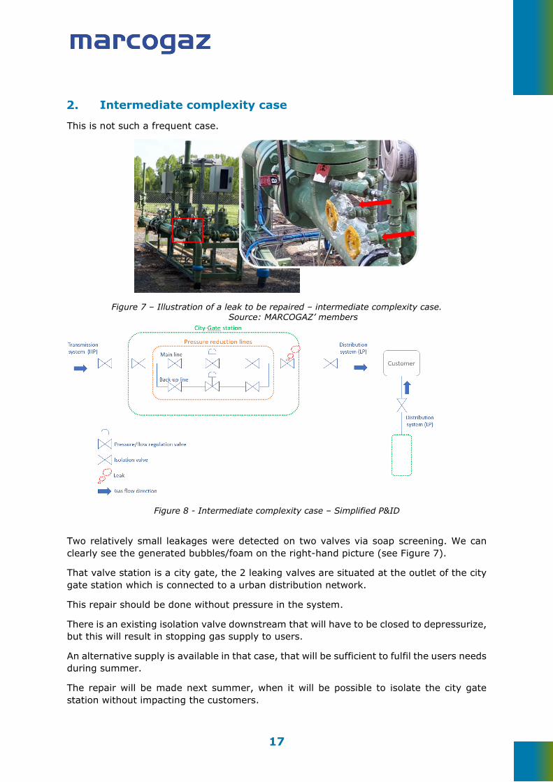
Intermediate complexity case
This is not such a frequent case.
Figure 7 – Illustration of a leak to be repaired – intermediate complexity case. Source: MARCOGAZ’ members
Figure 8 - Intermediate complexity case – Simplified P&ID
Two relatively small leakages were detected on two valves via soap screening. We can clearly see the generated bubbles/foam on the right-hand picture (see Figure 7).
That valve station is a city gate, the 2 leaking valves are situated at the outlet of the city gate station which is connected to a urban distribution network.
This repair should be done without pressure in the system.
There is an existing isolation valve downstream that will have to be closed to depressurize, but this will result in stopping gas supply to users.
An alternative supply is available in that case, that will be sufficient to fulfil the users needs during summer.
The repair will be made next summer, when it will be possible to isolate the city gate station without impacting the customers.
18
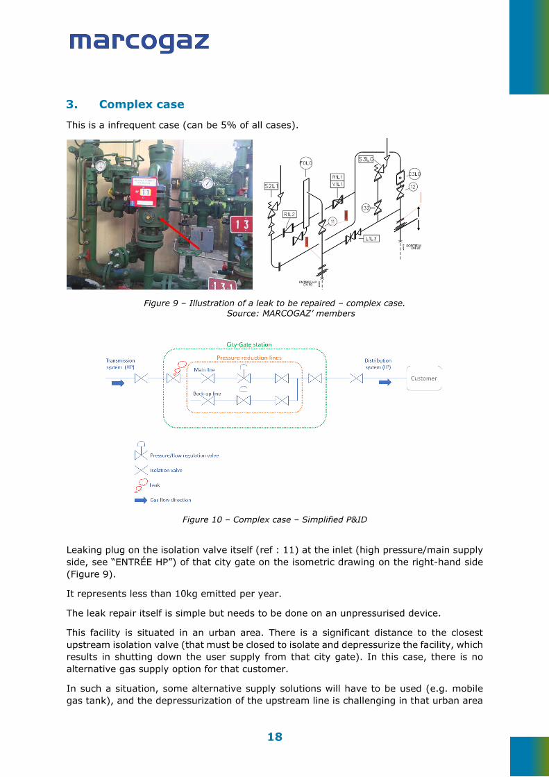
Complex case
This is a infrequent case (can be 5% of all cases).
Figure 9 – Illustration of a leak to be repaired – complex case. Source: MARCOGAZ’ members
Figure 10 – Complex case – Simplified P&ID
Leaking plug on the isolation valve itself (ref : 11) at the inlet (high pressure/main supply side, see “ENTRÉE HP”) of that city gate on the isometric drawing on the right-hand side (Figure 9).
It represents less than 10kg emitted per year.
The leak repair itself is simple but needs to be done on an unpressurised device.
This facility is situated in an urban area. There is a significant distance to the closest upstream isolation valve (that must be closed to isolate and depressurize the facility, which results in shutting down the user supply from that city gate). In this case, there is no alternative gas supply option for that customer.
In such a situation, some alternative supply solutions will have to be used (e.g. mobile gas tank), and the depressurization of the upstream line is challenging in that urban area

19
and will request a specific set up. The environmental and financial cost/benefit of a dedicated intervention on that limited leakage will have to be carefully studied, and this will delay the repair.
It will be potentially more efficient to wait for an intervention opportunity on the main supply line in order to isolate and depressurize that city gate.
20
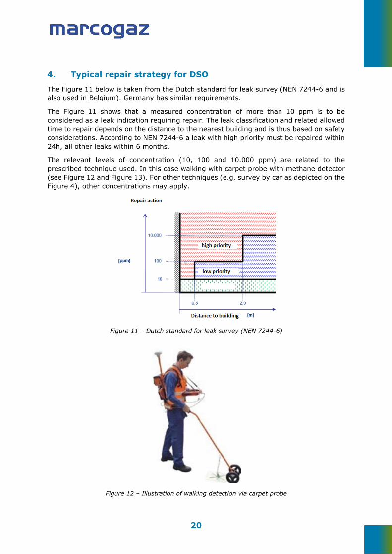
Typical repair strategy for DSO
The Figure 11 below is taken from the Dutch standard for leak survey (NEN 7244-6 and is also used in Belgium). Germany has similar requirements.
The Figure 11 shows that a measured concentration of more than 10 ppm is to be considered as a leak indication requiring repair. The leak classification and related allowed time to repair depends on the distance to the nearest building and is thus based on safety considerations. According to NEN 7244-6 a leak with high priority must be repaired within 24h, all other leaks within 6 months.
The relevant levels of concentration (10, 100 and 10.000 ppm) are related to the prescribed technique used. In this case walking with carpet probe with methane detector (see Figure 12 and Figure 13). For other techniques (e.g. survey by car as depicted on the Figure 4), other concentrations may apply.
Figure 11 – Dutch standard for leak survey (NEN 7244-6)
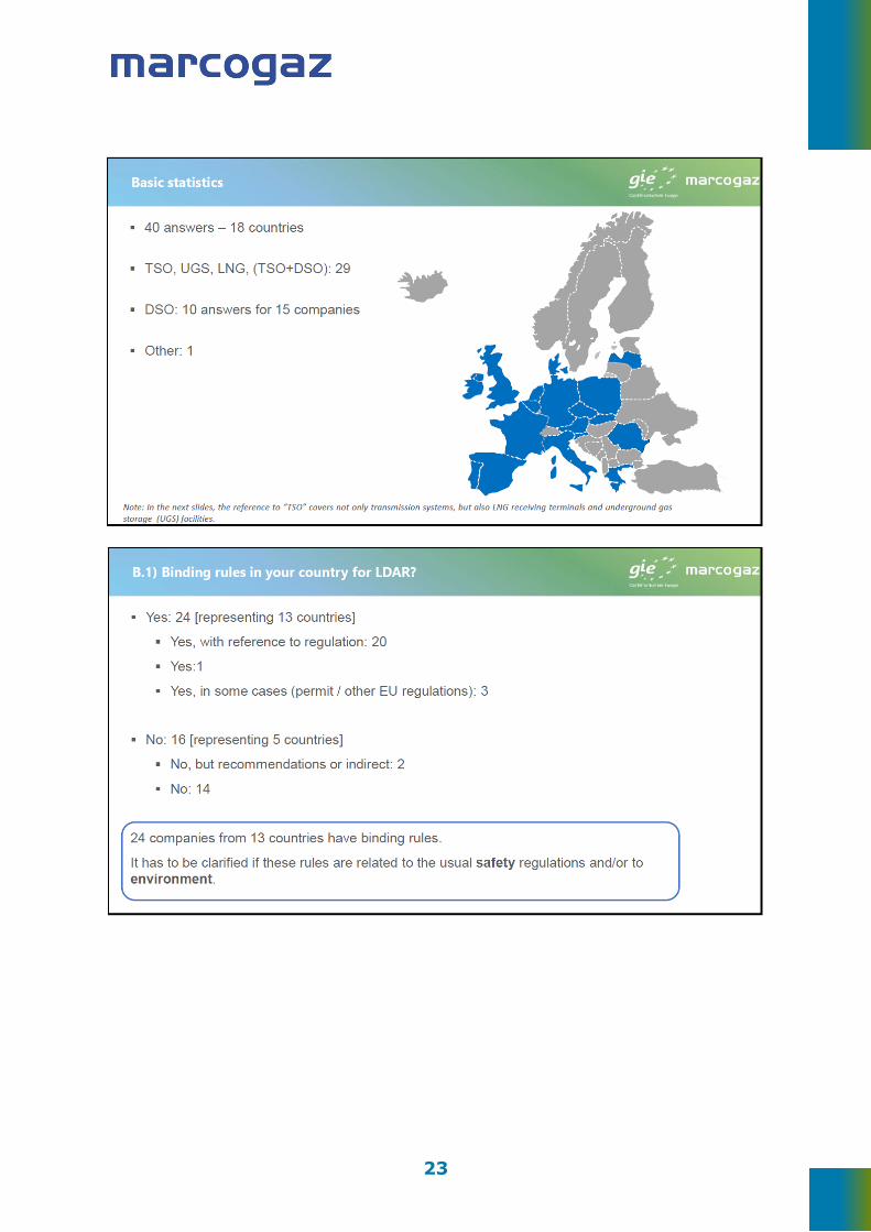
Figure 12 – Illustration of walking detection via carpet probe

21
Figure 13 – Carpet probe / methane detector

22
Annex II – LDAR survey performed by GIE and MARCOGAZ
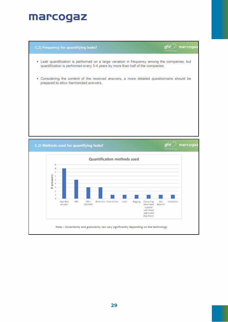
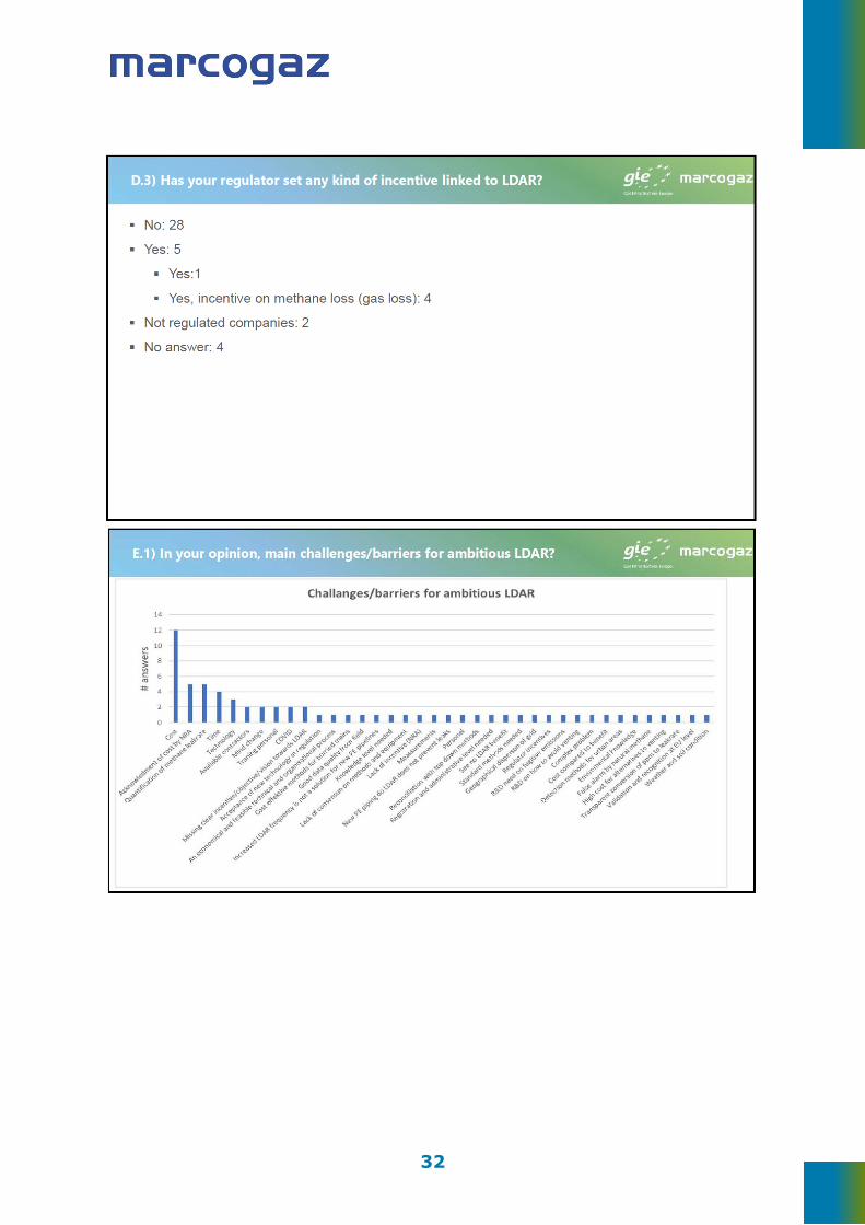
The following slides show the results of a MARCOGAZ/GIE survey on leak detection and repair (LDAR) programmes in the European mid and downstream gas sector. The answers to the questionnaire cover transmission, distribution, LNG receiving and underground storage activities in Europe.
The survey was performed in the autumn 2020 and a total of 40 answers were collected across the gas industry, and the covered topics included regulation, technical aspects and costs for LDAR.
The slides 1-24 were sent to the European Commission on the 23rd of December 2020.
The remaining slides with comments were used to clarify follow up questions on some details in a meeting on the 21st January 2021.
Slides 1-24 (23/12/2020)
23

24

25

26

27

28
29

30

31
32
33
Remaining slides (21/01/2021)
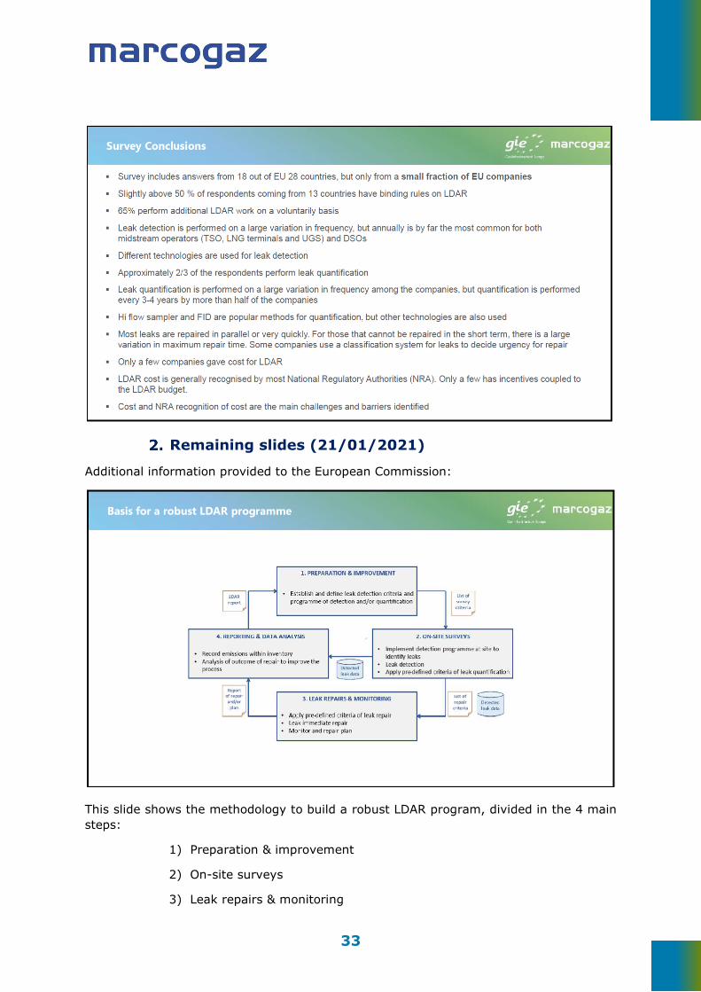
Additional information provided to the European Commission:
This slide shows the methodology to build a robust LDAR program, divided in the 4 main steps:
1) Preparation & improvement
2) On-site surveys
3) Leak repairs & monitoring
34
4) Reporting & data analysis
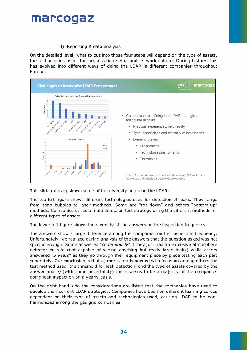
On the detailed level, what to put into those four steps will depend on the type of assets, the technologies used, the organization setup and its work culture. During history, this has evolved into different ways of doing the LDAR in different companies throughout Europe.
This slide (above) shows some of the diversity on doing the LDAR.
The top left figure shows different technologies used for detection of leaks. They range from soap bubbles to laser methods. Some are “top-down” and others “bottom-up” methods. Companies utilize a multi detection test strategy using the different methods for different types of assets.
The lower left figure shows the diversity of the answers on the inspection frequency.
The answers show a large difference among the companies on the inspection frequency. Unfortunately, we realized during analysis of the answers that the question asked was not specific enough. Some answered “continuously” if they just had an explosive atmosphere detector on site (not capable of seeing anything but really large leaks) while others answered “3 years” as they go through their equipment piece by piece testing each part separately. Our conclusion is that a) more data is needed with focus on among others the test method used, the threshold for leak detection, and the type of assets covered by the answer and b) (with some uncertainty) there seems to be a majority of the companies doing leak inspection on a yearly basis.
On the right hand side the considerations are listed that the companies have used to develop their current LDAR strategies. Companies have been on different learning curves dependant on their type of assets and technologies used, causing LDAR to be non-harmonized among the gas grid companies.
35
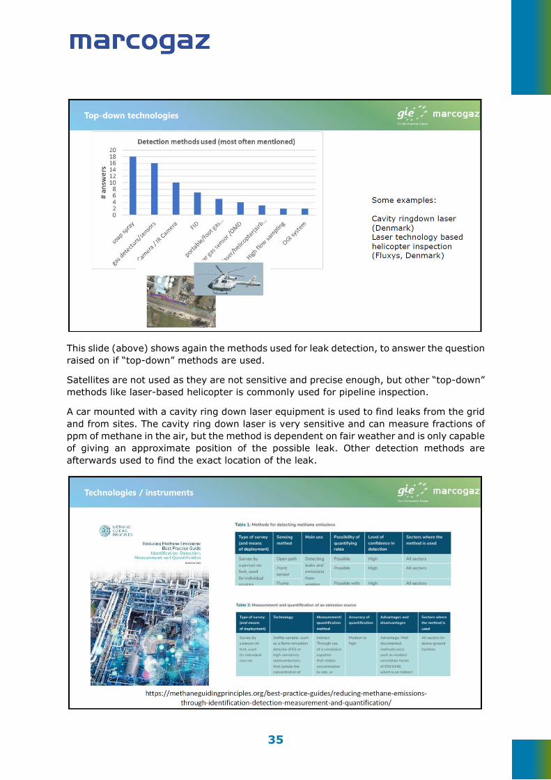
This slide (above) shows again the methods used for leak detection, to answer the question raised on if “top-down” methods are used.
Satellites are not used as they are not sensitive and precise enough, but other “top-down” methods like laser-based helicopter is commonly used for pipeline inspection.
A car mounted with a cavity ring down laser equipment is used to find leaks from the grid and from sites. The cavity ring down laser is very sensitive and can measure fractions of ppm of methane in the air, but the method is dependent on fair weather and is only capable of giving an approximate position of the possible leak. Other detection methods are afterwards used to find the exact location of the leak.

36
MARCOGAZ has been deeply involved in the development of the Methane Guiding Principles “Best Practice Guide on Reducing methane emissions: Identification, detection, measurement and quantification”. This guide contains a good overview on the current and emerging technologies (main use, level of confidence, accuracy, advantages and disadvantages, …).
This is the reason why additional details were not added into the MARCOGAZ technical recommendation on LDAR.
The gas industry uses correlation factors to quantify methane emissions rates (i.e. to convert ppm obtained with a certain technology into a rate). The current correlation factors were not designed for the gas assets/sources and they add, therefore, uncertainty to the estimation of methane emissions. That is the reason why MARCOGAZ recommends defining specific correlation factors.
The next step would be to evaluate if an R&D project (potentially under the umbrella of GERG) could be launched to obtain specific correlation factors for the gas sector. Once these factors are defined, the proposal should be submitted to CEN to start the standardization process.
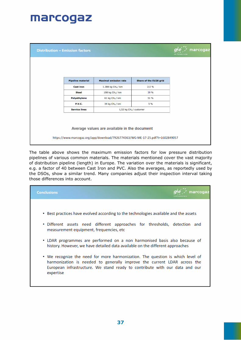
37
The table above shows the maximum emission factors for low pressure distribution pipelines of various common materials. The materials mentioned cover the vast majority of distribution pipeline (length) in Europe. The variation over the materials is significant, e.g. a factor of 40 between Cast Iron and PVC. Also the averages, as reportedly used by the DSOs, show a similar trend. Many companies adjust their inspection interval taking those differences into account.