le l - defense technical information · pdf filei 7 us army test and evaluation command test...
TRANSCRIPT
UNCLASSIFIED LE - L 'SECURITY CLASSIFICATION OF THIS PAGE (When Dog& Entered)
REPORT DOCUMENTATION PAGE aE MPLETING FORMSEP 2.GOVT ACCESSION NO. 3. RFCIPIFNT'S CATALt!G NUMBER
- ~ ~ U ARYTS N EVALUATION COMM4AND Tinal ~ ~~OOCVEE
$VHILETEST FACILITIES ATkBERDEF'I PROVING..RU ________________________MM
mum..~ S. B1TflIT Il 0.-T NUMBERf(O)
9. PERFORMING O~AIAINNMLAND ADDRESS IkO. PROGRAM ELEMENT, PROJECT, TASKAREVA 6 WORK UN IT NUMBERS
F US ARMY ABERDEEN PROVING GROUND (STEAP-MT-M)ABERDEEN PROVING GROUND, MARYLAND 21005 DARCOM-R 310-6
I I. CONTROLLING CTFICE N ?%ME AND ADDRESS 1 Z~ ..-
US ARMY TEST AND EVALUATION COMMAND (DRSTE-AD-MyJ 6 Ju l 8
F 1 4. MONITORING AGENCY NAME G ADORESSý:l different fromi Controlling Office) 1S. SECURITY CLASS. (of this report)
DS ISTRIBUTION STATEMENT (of this Report)
Approved for pUblic release; distribution unlimited.
17. DISTRIBUTION STATEMENT (of the abstract entered In Block 20, If different from Report)
S IS. SUPPLEMENTARY NOTES
19. KEY WORDOS (Continue on rev~ree side if noceeeuy end Identify by block nwmber) JI
Automotive Test Courses Road TestBridging (Obstacle) TransportabilityLoad Vibration Test Course Vehiclr- Test CoursesMobility WeaponI Vehicle-mounted
20. ABSTRACT (ainthue -m revurse ofil N necessay amm idenilf) by block numnber)
<'Describes Aberdeen Proving Ground facilities for testing wheeled and tracked(vehicles including vehicular weapon facilities. Includes photographs anddrawings showing test course dimensions and characteristics. Does not coverequipment and instrumentation used on the courses, nor laborAtory facilitiesexcept for climatic test chambers
EDITION OPSECURITY CLASSIIICATtOII OF THIS PAGE (When, Diet& EnIMed)
S1 26 019

I 7
US ARMY TEST AND EVALUATION COMMANDTEST OPERATIONS PROCEDURE
DRSTE-RP-702-102*Test Operations Procedure 1-1-011 6 July 1981AD No.
VEHICLE TEST FACILITIES AT A3ERDEEN PROVING GROUNDPage-
Paragraph 1. SCOPE .................... ........................ 12. CHURCHVILLE TEST AREA ........ ................ . 43. CLIMATIC TESriNG FACILITIES ........ ............. 74. DYNAMOMETER COURSE ............... ................. 75. MILE LOOP .................. ..................... 86. MOUNTAIN HIGHWAY ....... .................. . 117. MUNSON TEST AREA ....... .................. .. 138. PERRYMAN TEST AREA ....... ................. .. 429. POOLE'S ISLAND ................... . 4910. TANK GUNNERY RANGES ...... ................... 5011. TILT TABLE ........... ..................... ... 56
Appendix A. REFERENCES ............. ..................... .. A-i
1. SCOPE. This TOP describes the mobility test facilities of Aberde.,n ProvingGround (APG), Maryland. It is designed for use in planning tests of wheeled andtracked vehicles, including vehicuhlr weapon sy3tems. It does not cover theequipment and instrumentation used on the test courses to obtain and measure testdata, or laboratory facilities except for the climatic test chambers.(Automotive laboratory instrumentation and field t st equipment and instrumenta-tion are covered in TOP/MTP 2-1-002 and 2-1-00.'5 , respectively.) 'he testfacilities at APG are adequate to meet the needs of the DARCOM mobility model,HIL-M-8090F, and the automatic shock test (Procedure 514.2) of MIL-STD-810C.
At APG, there are nbout 64 km (40 miles) of automotive test courses on more than1320 hectares (3,300 acres) of land, in addition to the water areas and firingranges used in vehicle testing. Each course is designed to meet a particularmilitary vehicle specification, and many of the coursef exceed commercial stan-dards. Test course severity is covered in TOP 1-1-010.• -, :-r
*This TOP supersedes TOP/MTP 1-1-011 dated 17 March 1976. : 'mt
**Footnote numbers correspond to reference numbers in Appendix .11, .
Approved for public release; distribution unlimited.
v .i Co( I ' t
v0I 1P
"WHO'.,t .L'i•

6 July 1981 TOP 1-1-011
TABLE ICOURSE COMPOSITION AND LENGTHS
Test Couiz ae iegt~h[described on pAge in () English Metric
CHURCHVILLE TEST AREA (4)Hilly Cross-Country (4)
Course A: Virgin wooded terrain in-cluding brush, stone, atumps,side slopes, ravines
Course B: Native soil and stone,grades to 29%
Hilly Secondary Road (C)(6) Grades to 10% 1.5 mi 2.4 kmPrepared Mud Slopes (6) Loami 10% 220 ft 67 m
15% 250 ft 76 m_ 20% 220 ft 67 m
DYNAMOMETER COURSE (7) Bituminous concrete 1 mi 1.6 Km____L _ OP" (8) Paved and gravel i=m' 1.6 km
Winch Test Facility (10) Concrete basePothole-Crosstie Course (10) Concrete potholes 200 ft 61 m
Wooden crossries in concrete 132 ft 40 m1-inch Bump Course (11) Iron rods in concrete 220 ft 67 m
MOUNTAIN HIGHWAY (11) Paved 40 mi 64.4 kmMUNSON TEST AREA (13)
High Speed Paved Road (15) Bituminous concrete 2,235 ft 681 mImproved Gravel Road (16) Compacted bank gravel 10,714 ft 3266 mRolling Hill Course (17) Compacted stone/dust 2.034 ft 620 mSand Course (18) Washed beach sand 503 1t 153 mClay Soil Bin (19) Patapsco red clay 3?5 ft 39 mAbrasive Mud Course (20) Sand loam 240 x 950 ft 73 x 290 w.Marsh (21) INatural mudFording Basin (22) Concrete 270 ft 82 mUnderwater Fording (23) Concrete 315 ft 96 m
FacilityApphibian Ramp (23) Bituminous conere.te 20 x 50 ft 6 x 15 mShallow Water Swimming (24) Channel, 10 ft deep 1,000 ft 305 m
Area x 50 ft wide (3 m Y. 15 w')leading to Bay
Belgian Block Course (25) Granite blocks in concrete 3,940 ft 1201 mImbedded Rock Course (26) Grantte stones in concrete 800 ft 244 m
Side Slopes (27) Concrete: 20% 271 ft 83 m30% 723 ft 220 m35% 100 ft 31 m40% 300 ft 91 m
Gradeability elapes (28) Asphalt: 5% 483 ft 147 m7% 185 ft 56 w
10% 300 ft 91 m15% 256 ft 78 m20% 199 ft 51 m
2
6 July 1981 TOP 1-1-011
Test Course T Length
Gradeability Slopes Concrete: 30% 149 ft 45 m40% 112 ft 34 a45% 58 ft 18 a50% 97 ft 30 m.
60% 81 ft 25 m
Simulated Loading Ramp (29) Concrete 40 ft 12 a
2-inch Washboard (30) Concrete 822 ft 251 m
2- to 4-inch Radial (31) Concrete 243 ft 74 m
Washboard3-inch Spaced Bump (32) Concrete 764 ft 233 m
6-inch Washboard (33) Concrete 798 ft 243 m
Wave Course (34) Concre.te 443 ft 135 m
5- to 12-inch 3taggered (35 Concrete 230 ft 70 m
BumpVertical Walls (36) Concrete and wood
Bridging Device (37) Steel
Ditch Prof ile (38) Concrete 25 ft 6 in 7.8 m
Turning Circle (38) Concrete 250 ft 76 m(diameter)
Winch Test Facility (40) Concrete base
Load Vibration Course (40) (miscellaneous) 9,786 ft 2983 m
Fuel Consumption Course (41) (miscellaneous) 8,003 ft 2439 m
PERRYMAN TEST AREA (42)CroCs-Country courses: 1 Moderate; native loam with 5.2 mi 8.4 km
(42) quarry spall/gravel2 Moderat" rough; native loam 1.8 mi 2.9 km
with qua.ry spall3 Rough; native loam 3.3 mi 5.3 km
4 Severe; native loam with 2.5 mi 4 km
natural marsh
Deep Water Fording (47) Earth bottom covered with metal 200 ft 61 m
Facility screens
High Speed Paved Road (47) Bituminous concrete (including 3.8 mi 6.1 km
turnarounds)
Mud Bypass Course (47) Native loam ?repared by tilling 700 ft 213 m
Mud Mobility Course (47) Native soil prepared by tilling 410 ft 125 m
Mobile Bridge Test Facility Pond an deep as 2 m (7 ft) 225 ft 69 m
Secondary Roads: A (47) Native soil 2.4 mi 3.9 km
B (47) Bank gravel/crushed stone 3.2 mi 5.1 km
Swamu Quarter Mobility Aree Swamp; soft soil; "rice" 2 ac .8 ha
POOLE'S ISLAND (49) Beach sand sloping to 5-m (15-ft) 1 mi 1.6 kmwater depth
-TANK GUR (50) Rangesfor direct fire; moving max. range
target; cross-country courses 5,500 mi 8851 km
Cross-country loop, native loam 1 mi 1.6 km
T T E (56) Steel, 3.7 m x 4 m (12 ft x12 ft 6 in)
3
6 July 1981 TOP 1-1-011
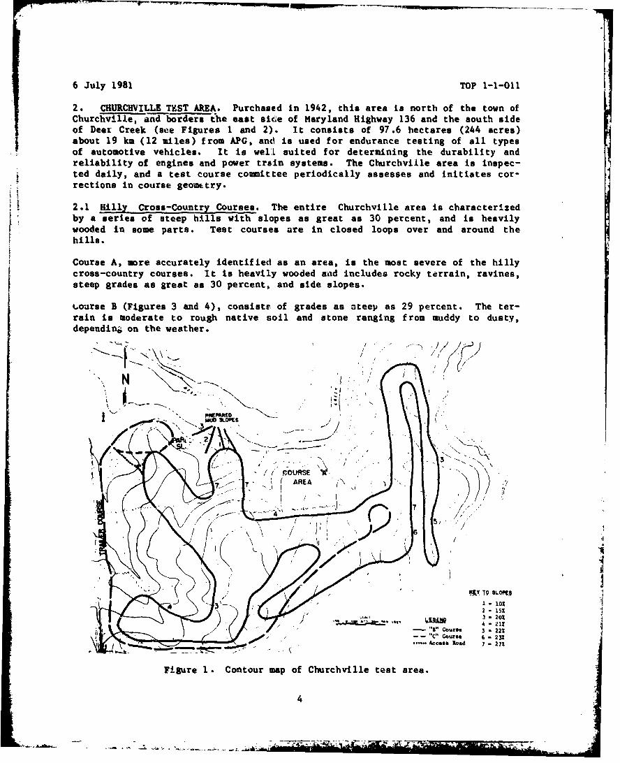
2. CHURCHVILLE TEST AREA. Purchased in 1942, this area is north of the town ofChurchville, and borders the east side of Maryland Highway 136 and the south sideof Deer Creek (see Figures 1 and 2). It consists of 97.6 hectares (244 acres)about 19 km (12 miles) from APG, and is used for endurance testing of all typesof automotive vehicles. It is well suited for determining the durability andreliability of engines and power train systems. The Churchville area is inspec-ted daily, and a test course committee periodically assesses and initiates cor-rections in course geometry.[I2.1 Hilly Cross-Country Courses. The entire Churchville area is characterizedby a series of steep hills with slopes as great as 30 percent, and is heavilywooded in some parts. Test courses are in closed loops over and around the
Course A, more accurately identified as an area, is the most severe of the hillycross-country courses. It is heavily wooded and includes rocky terrain, ravines,steep grades as great as 30 percent, and side slopes.
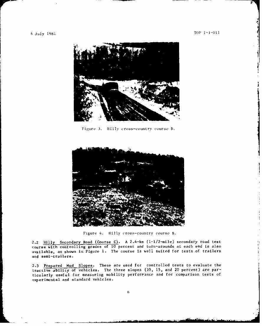
.wourse B (Figures 3 and 4), consists of grades as steep as 29 percent. The ter-rain is moderate to rough native soil and stone ranging from muddy to dusty,dependin& on the weather.
" MUD S•OlLO PESI N
-~ N K COURSE )
"/ / O/• -
' A R E A
," N
/ \/ ,
J" M-IY TQ SLO9P
1 -101
3-201118" Curse - 22Z12"C" course 6 - 22%
'Ac ....- Access Road 7 - 27%
Figure 1. Contour map of Churchville test area.
4
iAi
5L
6 July 198i TOP 1-1-011
4'1
IJ
Figure 3. Hilly cross-country course B.
Figure 4. Hilly cross-country course B.
2.2 Hilly Secondary Road (Course C). A 2.4-k•i (1-1/2-mile) secondary road testcourse with controlling grades of 10 percent and torn-arounds at each end is alsoavailable, as shown in Figure 1. The course is well suited for tests of trailersand semi-trailers.
2.3 Prepared Mud Slopes. These are used for controlled tests to evaluate the
tracrive ability of vehicles. The three slopes (10, 15, and 20 percent) are par-
ticularly useful for measuring mobility perforrance and for comparison tests ofexperimental and standard vehicles.
6

6 July 1981 TOP 1-1-011
3. CLIMATIC TESTING FACILIVrIES. The facilities described in the table beloware used for simulated climatic testing of a variety of equipment at APG. Someof these chambers are of the proper size and capacity to accommodate automotivevehicles.
TABLE 2CLIMATIC TEST CHAMBERS
Characteris•cis FirIng:Door Size Chamber Size Max Wpn.
Facility Width Height Width Length Height Temp. Range Bore Cap.
Chamber 1 124 In 124 in 15 ft 24 ft 1OftlOin -70 to +160F 155-mm(315 cm 315 cm 4.6 m 7.3 m 3in25cm -21 to +71C)
Chamber 2 112 in 91 in lOft8in 19 ft 1oft91n -70 to +165F 105-mm(284 cm 231 cm 3m2Ocm 5.8 m 3m23cm -21 to +74C)
Chamber 3 164 in 138 in 13ft6in 28ft4in 13ftllin -70 to +165F 175-mm(417 cm 351 cm 4ml5cm 9ml0cm 4m28cm -21 to +74C)
Conditioning 177 in 140 in 23ft8in 41fr7in 14 ft 0 to +150F N/ARoom (450 cm 356 cm 7m20ciNm 13ri.8cm 4 m 0 to, +66C)
*Stratosphere 98 in 72 in 8ft2in 9 ft 6ft6in -70 to +160F 40-mm
(249 cm 183 cm 2m5cm 3 m 2ml5cm -21 to +71C)
Simulated 168 in 174 in 24ft6in 34ft6in 14 ft (variable rainfall toRain (427 cm 442 cm 7m15c-t 10ml5cm 4 m) 61 cm [24 in] per hour)Facility
*The barometric pressure of the stratosphere chamber can be dropped to a pressureequivalent to 30500-meter (100,000-foot) altitude. The other chambers are at am-bient barometric pressure.
4. DYNAMOMETER COURSE. This course is in the Michaelsville area of APG, 4 milesfrom headquarters (see Figure 5). Constructed of reitdorced concrete, with a hotmixed bituminous surface, it is suitable for operating the heaviest track-layingvehicles. The course hes a total gradient of less than 0.1 percent in its 1.6-km(1-mile) length, and turn-arounds are provided at each end. It is used forclosely controlled engineering tests such as drawbar pull and tractive resistancemeasurements, acceleration and braking tests, and fuel consungtion measurements.
7
S. ...... :.. .• 1. . , ,- - . , .

6 July 1981 TOP 1-1-011
Figure 5. M-2 Infantry Fighting Vehicle undergoingdrawbar pull test on dynamometer course.
5. MILE LOOP. This oval-shaped facility was originally constructed ia 1933 asa level concrete course for continuous high-speed operating tests of vehicles(aee Figure 6). Situated near APO headquarters, the Mile Lc09 consists of twostraight sections, each .4 km (1/4 mile) long, joined at each end by 0.4-km sec-tions of regular curvature to form an oval totalling 1.6 km iu circumference.
The course has been modified by covering and maintaining the surface with hotmixed bituminous concrete and by adding a gravel surface parallel to and outsidethe oval. Several facilities have also been added in the area, as describedbelow
8
.9
I
I
I
a 4
$
I
C
49
9
6 July 1981 Tor 1-1-011
5.1 Winch Test and Tie-down Facility. This device has a restraining capabilityof 45360 kg (100,000 po-ands), and is used mainly as an anchor during winch en-durance testing.
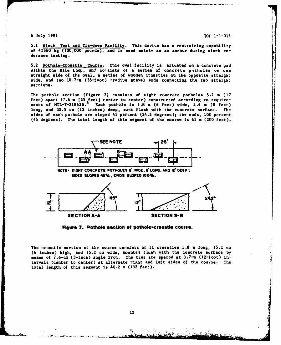
5.2 Pothole-Crosstle Course. This oval facility is situated on a concrete padwithin the Nile Loop, anA cosiats of a series of concrete potholes on onestraight side of the oval, a series of wooden crossties on the opposite straightside, and two 10.7-a (35-foot) -radius gravel ends connecting the two straight Nsections.
The pothole section (Figure 7) consists of eight concrete potholes 5.2 a (17feet) apart (7.6 a 125 feet) center to center) constructed according to require-ments of MIL-T-21863D. Each pothole is 1.8 a (6 feet) wide, 2.4 m (8 feet)long, and 30.5 ca (12 inches) deep, sunk flush with the concrete surface. Thesides of each pothole are sloped 45 percent (24.2 degrees); the ends, 100 percent
(45 degrees). The total length of this segment of the course is 61 m (200 feet).
SEE NOTE 25' i.
NOTE' EIGHT CONCRETE POTHOLE! G' WIDE, le LONG, AND It DEEP;SImS SLOMD 45%, END$ SLOPED 100%.
45 2426
SECTION A-A SECTION Bo-
FIgure 7. Pothole section of potholo-orosetle courte.
The crosatie section of the coucse consists of 11 crosaties 1.8 m long, 15.2 ca(6 inches) high, and 15.2 cm wide, muntei flush with the concrete surface bymeans of 7.6-cm (3-inch) angle iron. The ties are spaced at 3.7-r (12-foot) in-tervals (center to center) at alternate right and left sides of the coule. Thetotal length of this segment is 40.2 m (132 feet).
10
-' .'
6 July 1981 TOP 1-1-011
5.3 1-Inch Dup Course. The 2.5-cm (1-inch) bumps are iron rods 4.3 m (14 feet)long, 5 cm (2 inches) wide, and 2.5 cm high, mounted on the flat concrete surfacein the center of the pothole-croestie course. A total of 39 1-inch btms arespaced at random 1.5- and 1.8-a (5- and 6-foot) inttrvals perpendicular to thedirection of travel in accordance with MIL-M-008090 . The course length is 67 m(220 feet).
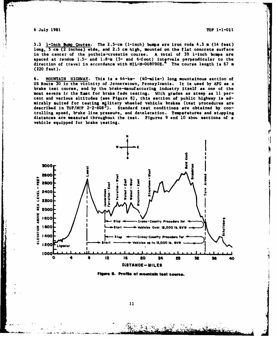
6. MOUNTAIN HIGHWAY. This is a 64-k.- (40-mile-) long mountainous section ofUS Route 30 in the vicinity of Jennerstown, Pennsylvania. It is used by APC as abrake test course, and by the brake-manufacturing industry itself as one of themost severe ic the East for brake fade testing. With grades as steep as 11 per-cent and various altitudes (see Figure 8), this settion of public highway is ad-mirably suited for testing military wheeled vehicle brakes (test procedures aredescribed in TOP/WfP 2 -2- 6 0 8 J). Standard test conditions are obtained by con-trolling speed, brake line pressure, and deceleration. Temperatures and stappingdistances are measured throughout the test. Figures 9 and 10 shou. sections of avehicle equipped for brake testing.
"it I
,. oo1 , -. •3.000
ha II,\ . _ • It
0o 1800 -PL •- Stop -0- Cres- Country Procedure for -
1I6-O 3 1600 so Start Vehicles Over 1.,000 lb. SVW0 :I S , , . -~ .=1.400 Stop ~-Cross- Comatvy Proedersfre
he 1 -0 Start 1 - Vehicles up to 2,000 lb. OVW
1000aSlcs1 1 . 10 4 II to 20 24 to 3t 36 40
DuSTANCE- MILES
Figue S. Profile of mountain test ecwoe.
11

6 July 1981 TOP 1-1-011
4
144
I Figure 9. Brake testing instrumentation installed in truck cab.
Figure 10. Fifth wheel attached to M-1 for brake test.
12
b .

6 July 1981 TOP 1-1-011
7. MUNSON TEST -AREA. Located near the eastern boundary of APG and borderingthe shores of the Spesutie Island Narrows portion of the Chesapeake D~ay, theMunson Test Area encompasses about 60 hectares (150 acres) of land. The facilityis named in honor of Lt. Max Munson who lost his life in 1941 while testing anexperimental vehicle.
The test courses are designed for making specific measurements and determinationsof vehicle performance in the field. All special obstacles and test roads arepermanently constructed and maintained according to specifications. The coursesand network of connecting roads total 14.5 km (9 miles). Figure 11 shows rela-tive locations of the courses, and Figure 12 is an aerial view.
'~~~ SPOEED•
pPV
kOOOE
DITCH PROFILEI. e/20%
vtRMN , it,"g
NOT SHOWN mA .
FUEL CO#$UMTIO4 CU4JR. ( p 31 I /,
I.OAO VIBRA&TIONl C;:ORS[" I P 32 }"
I Figure 11. Munson test area.
S13
-. ~ ~ -. t ' . ..
WA Cea,
$41
141
tuii

6 July 1981 MfP 1-1-011
7.1 High Speed Paved Road. This is a level road (see Figures 13 and 14) thatpermits the operation of most military vehicles at maximum speed. It provides asharp contrast in operating conditions when used as part of a loop including theBelgian block course. This road is one of two used for high speed operation; theother is in the Perryman area.
4
15- 0' 15-0"
0'- 3'- 0"
1/6" PER VT. TO CROWN
II2"BINDER a 2"WEAR COURSE RESURFACED IN 19452"'EAR COURSE RESURFACEO IN 1955---
LENGTH OF COURSE, 2,235 FT
Figure 13. Cross-section of high speed paved road.
Figure 14. High speed paved road.
15
Aga.~

AN .*- M -ou
6 July 1.981 Top 1-1-011
7.2 I!Mproved Qr&vel load. This is a loop of about 3.2 ka (2 miles) with leftand right curves (see Figures 15 and 16); the surface is compacted gravel main-tained by grading. The gravel road Is one of four basic course used for en-durance testing; the others are a payed road and level cross-country in the
Perrywan area and the cross-country h~ill course in the Churchville area.
20- P" 26-0"
V COMPACTED GRAVEL-'
NOTE wiDTH OF ROAD VARIES
LENGTH OF COURSE, 10,714 FT.
Figure 15. Cross-section of gravel road.
16W 1Figure 16. Improved gravel road.

--- ,-~ -- ~~-,, ------. ---IMMIO -
6 July M9 i. TOP 1-1-011
7.3 Rolling Hill Course. This was designed to provide short, closely spacedgrades. As a vehicle alternates between lip- and down-,grades on this caurse (seeFigures 17 and 18), the engine and poster train are subjected to rapid variationsin loading. The surf ace consitits of~ crushed stone compacted with stone dustb~inder.
I __ _J0.01-0.00 3.00 4.CO 5.00 I..00 7.OC 7.50
"0C4" l.00 1.0 0 12-00 13.00 14.00 1!.0C' 15,.54
fit,
Figure 17. Profile of rolling hill course.
Figure 18. Rolling hill course.
17
6 July 1981 TOP 1-1-011
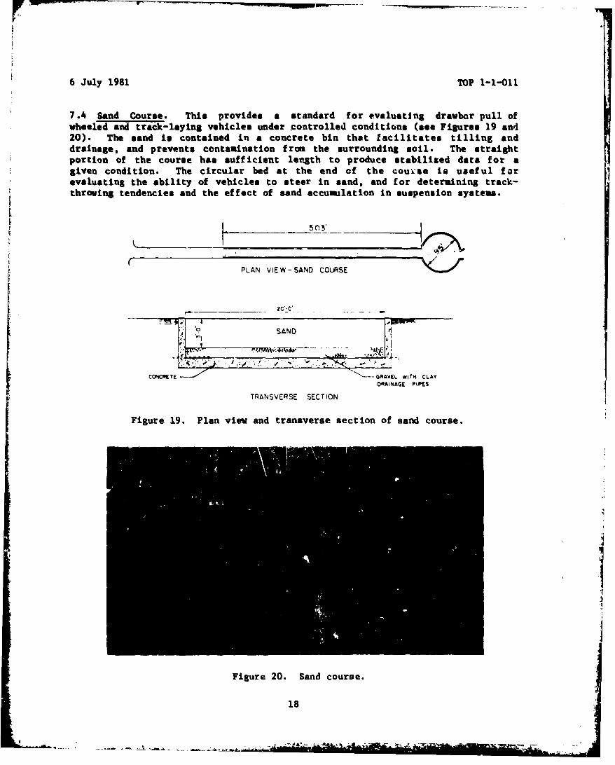
7.4 Sand Course. This provides a standard for evaluating drawbar pull ofwheeled and track-laying vehicles under controlled conditions (see Figures 19 and20). The sand is contained in a concrete bin that facilitates tilling anddrainage, and prevents contamination from the surrounding soil. The straightportion of the course has sufficient length to produce stabilized data for agiven condition. The circular bed at the end of the couvse is useful forevaluating the ability of vehicles to steer in sand, and for determining track-throwing tendencies and the effect of sand accumulation in suspension systems.
PLAN ViEW-SAND COLURSE
20 -C"
*..•.: ;... , .... ;..•.:...... .. I0 ~~SAND iS
* .: .J . '-L
CONCRETE - *"-GRAVl wITH CLAY
TRANSVERSE SECTION
Figure 19. Plan view and transverse section of sand course.
Figure 20. Sand course.
18

6 July 1981 TOP 1-1-011
7.v Clay Soil Bin. The mobility of test vehicles is quantitatively determinedin the f inely grained Patapsco clay of the soil bin (see Fi~tures 21 and 22).Soil preparation between test programs consists of leveling the clay surface andmaintaining a wet, slippery condition.
PL.AN VIEW
-. PAAPI~O CLAY Sk IL. ~ .
SECTIONI THRU :LA 5OtL BIN
LENGTH OF COURSE, 3ZGFT.
Figure 21. Plan view and cross-section of clay soil bin.
'MM
Figure 22. Vehicle in clay soil bin.
19
f
6 July 1981 TOP 1-1-011
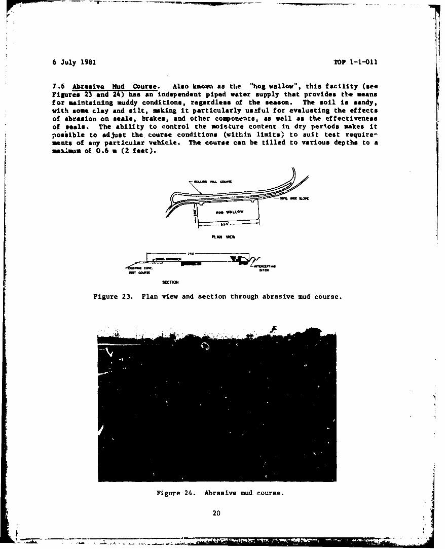
7.6 Abrasive Mud Course. Also known as the "hog wallow", this facility (seeFigures 23 and 24) has an independent piped water supply that provides the meansfor maintaining muddy conditions, regardless of the season. The soil is sandy,with some clay and silt, making it particularly us.ful for evaluating the effectsof abrasion on seals, brakes, and other components, as well as the effectivenessof seals. The ability to control the mois.ture content in dry periods makes itFpossible to adjust the course conditions (within limits) to suit test require-ments of any particular vehicle. The course can be tilled to various depths to amasmum of 0.6 a (2 feet).
PLAN EW
SECTION
Figure 23. Plan view and section through abrasive mud course.
Figure 24. Abrasive mud course.
20
6 July 1981 TOP 1-1-011
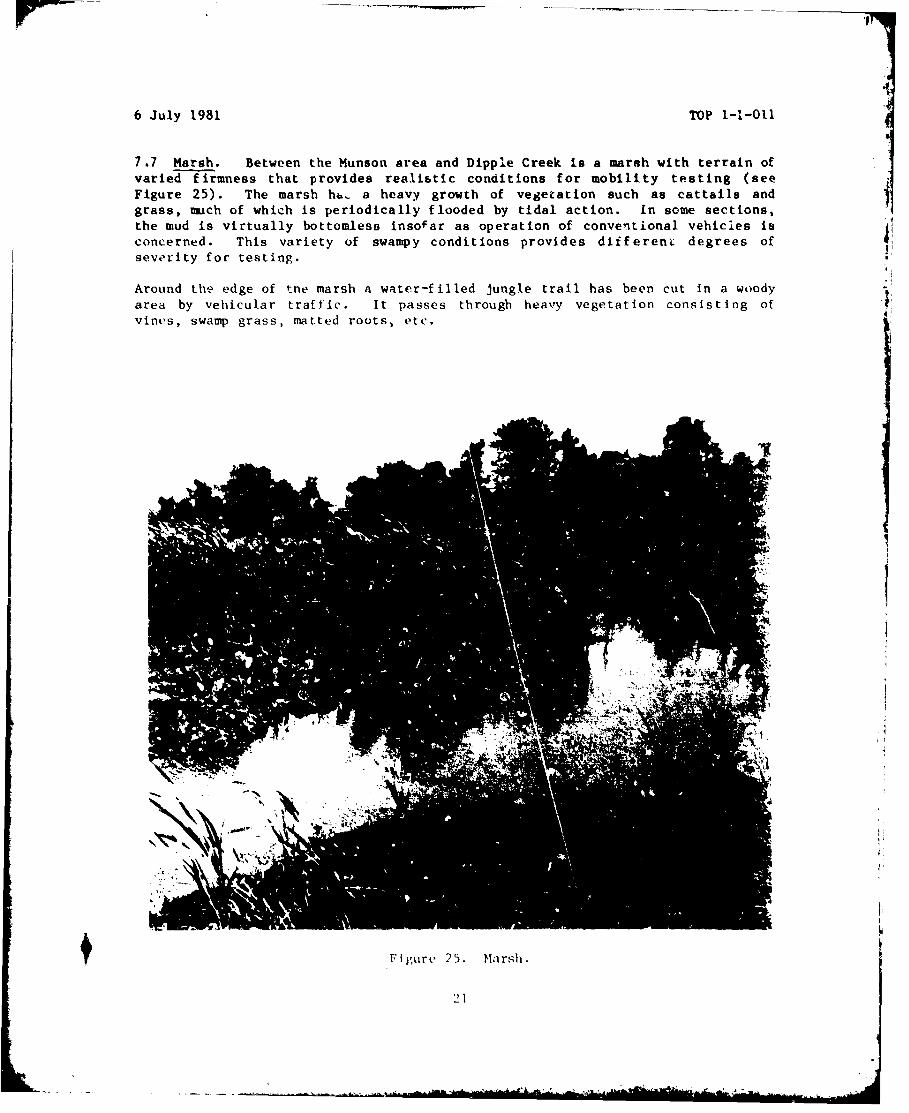
7.7 Marsh. Between the Munson area and Dipple Creek is a marsh with terrain ofvaried firmness that provides realistic conditions for mobility testing (seeFigure 25). The marsh hu. a heavy growth of vegetation such as cattails andgrass, much of which is periodically flooded by tidal action. In some sections,the mud is virtually bottomless insofar as operation of conventional vehicles isconcerned. This variety of swampy conditions provides differeni. degrees ofseverity for testing.
Around the edge of the marsh a water-filled jungle trail has been cut in a woodyarea by vehicular traffic. It passes through heavy vegetation consisting ofvines, swamp grass, matted roots, etc.
II
Sigure 25. Marsh
21
6 July 1981 TOP 1-1-011
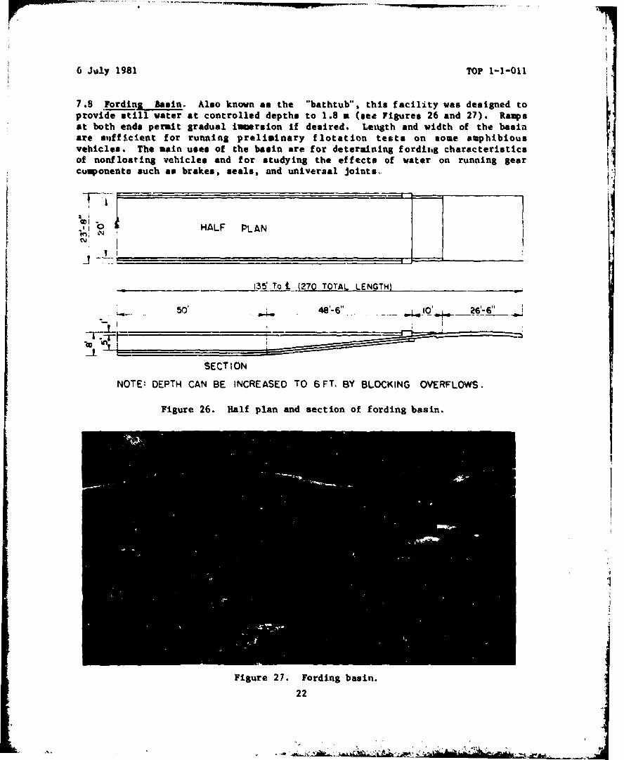
7.8 Fording Biasin. Also known as the "bathtub", this facility was designed toprovide still water at controlled depths to 1.8 a (see Figures 26 and 27). Rampsat both ends permit gradual immeruion if desired. Lenigth and width of the basinsire sufficient for running preliminary f lotation tests on some amphibiousvehicles. The main uses of the basin are for determining fordlitg characteristicsof nonfloating vehicles and for studying the effects of water on running gear icumponents such as brakes, seals, and universal joints.
0 HALF PLAN
135 To t. (270 TOTAL LENGTH)
5'48'-6" --IO4 6'-L
SECTION
NOTE: DEPTH CAN BE INCREASED TO 6 FT. BY BLOCKING OVERFLOWS.
Figure 26. Half plan and section of fording basin.
Figure 27. Fording basin.
22
6 July 1981 TOP 1-1-011
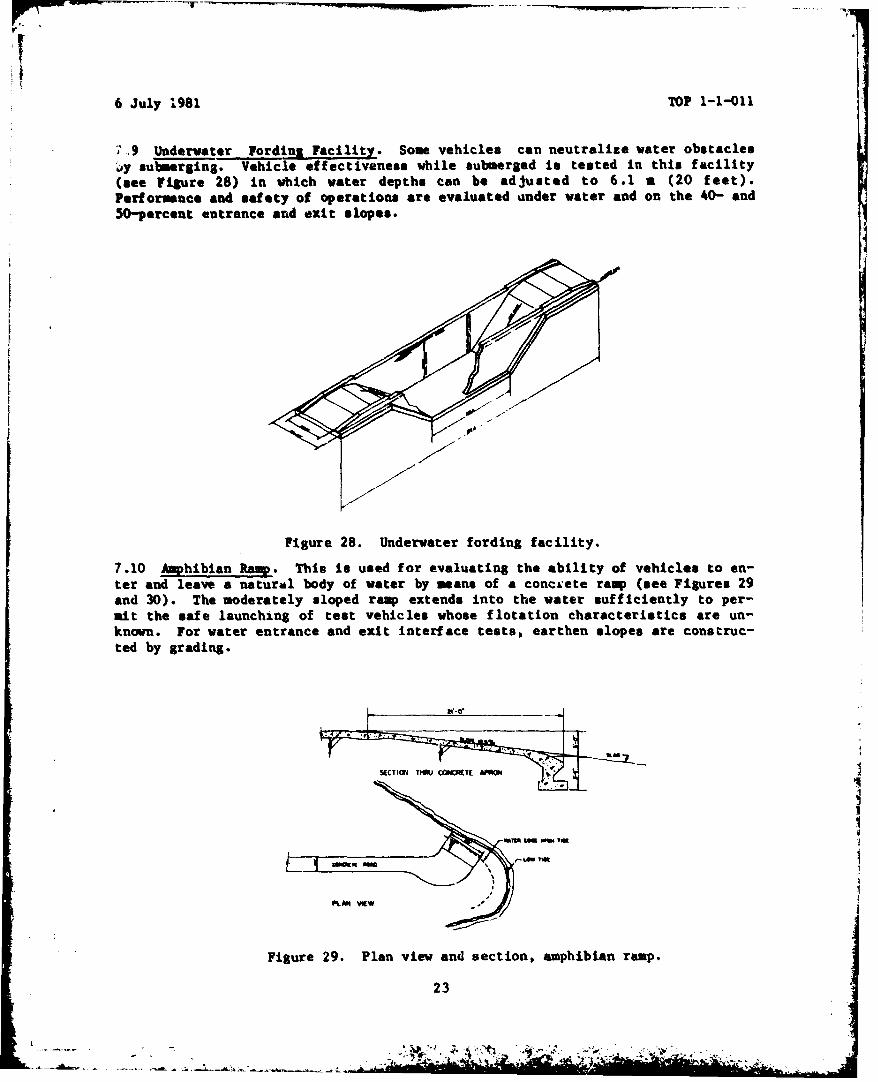
7.9 Underwater Fordina Facility. Some vehicles can neutralize water obstacles.y submerging. Vehicle effectiveness while submerged is tested in this facility(see Figure 28) In which water depths can be adjusted to 6.1 a (20 feet).Performance and safety of operations are evaluated ander water and on the 40- and50-percent entrance and exit slopes.
Figure 28. Underwater fording facility.
7.10 Amphibian Ramp. This is used for evaluating the ability of vehicles to en-ter and leave a natural body of water by means of a concaLete ramp (see Figures 29and 30). The moderately sloped ramp extends into the water sufficiently to per-mit the safe launching of test vehicles whose flotation characteristics are un-known. For water entrance and exit interface tests, earthen slopes are construc-ted by grading.
PLANl VIEW
Figure 29. Plan view and section, amphibian ramp.
23

6 July 1981 TOP 1-1-011
7.11 Shallow Water Swimming Area. The Spesutie Island Narrows has a 305-m
(1,000-foot) dredged channel 3 mn (10 feet) deep and 15 m (50 feet) wide, suitable
for evaluating the swimming and floating capabilities of amphibious vehicles in
still water. Fuel consumption and speed tests, as well as tests to evaluate
floating bridges and rafts, are conducted here. Entering Spesutie Narrows is by
way of the arphibian ramp. The Spesutie Narrows leads to deeper waters of the
Chesapeake Bay where further tests may be conducted if necessary. Rather large
vessels such as landing craft can gain access to the Munson area through the
Chesapeake Bay and the Spesutie channel.
24

16 July 1981 TOP 1-1-011
7.12 'Belgian Block Course. This facility is paved with unevenly laid granite
blocks f orming an undulating surface (see Figures 31 and 32). It duplicates the
rough cobblestone road found in many parts of the world. About 1.2 km (3/4 mile)
long, the course is useful as a standard roughi road f or accelerated testa of
wheeled vehicles, and is generally included In cycles of course@ used for vibra-
tion studies. The motion imparted to a vehicle is a random combination of roll
and pitch and high-frequency vibrations imparted by the granite paving blocks.
6"GRAVEL GRANITE 81-0ý:I5 IN CONJCeTET
LENGTH OF COURSE.3.9'4OFT
Figure 31. Transverse section, Belgian block course.
Figure 32. Belgian block course.
25
- -,A

6 July 1981 TOP 1-1-011
7.13 Imbedded Rock Course. This course (see Figures 33 and 34) provides an ex-tremely rough surface for testing wheeled vehicles. It not only has an irregularsurface suitable for evaluating suspensions, but is also a severe test forpneumatic tires.
8,-0" '8'-0" ..
•.•, .- - 2" 'TO 4" PPOTRUSION- -- GRANITE STONES 3
,, 77.,., ./4.- CONCRETE 6G
LENGTH OF COURSE, 8OOFT.
Figure 33. Transverse section of imbedded rock course.
14
Figure 34. Imbedded rock course.
26
'S. V . . .... ...
4.-', .
6 July 1981 TOP 1-1-011
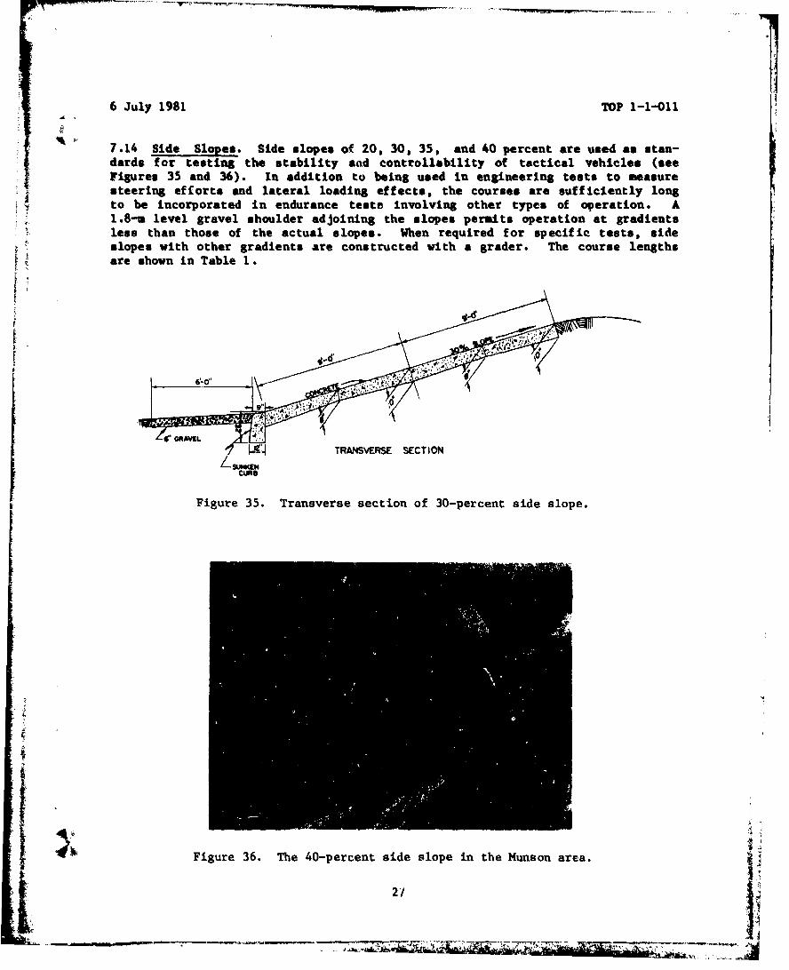
S* 7.14 Side Slopes. Side slopes of 20, 30, 35, and 40 percent are used as stan-dards for testing the stability and controllability of tactical vehicles (seeFigures 35 and 36). In addition to being used In engineering tests to measuresteering efforts and lateral loading effects, the courses are sufficiently longto be incorporated in endurance tests Involving other types of operation. A1.8-u level gravel shoulder adjoining the slopes permits operation at gradientsless than those of the actual slopes. When required for specific tests, sideslopes with other gradients are constructed with a grader. The course lengthsare shown in Table 1.
A'1
i•'49 GRAVEL•:
TRNVES SCTION
Figure 35. Transverse section of 30-percent side slope.
II
, Figure 36. The 40-percent side slope in the Munson area.
27
6 July 1981 TOP 1-1-011
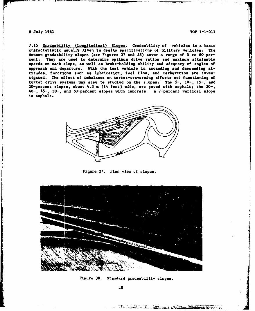
7.15 Gradeability (Longitudinal) Slopes. Gradeability of vehicles is a basiccharacteristic usually given in design specifications of military vehicles. TheMunson gradeability slopes (see Figures 37 and 38) cover a range of 5 to 60 per-cent. They are used to determine optimum drive ratios and maximum attainablespeeds on each slope, as well as brake-holding ability and adequacy of angles ofapproach and departure. With the test vehicle in ascending and descending at-titudes, functions such as lubrication, fuel flow, and carburetion are inves-tigated. The effect of imbalance on turret-traversing efforts and functioning ofturret drive systems may also be studied on the slopes. The 5-, 10-, 15-, and20-percent slopes, about 4.3 a (14 feet) wide, are paved with asphalt; the 30-,40-, 45-, 50-, and 60-percent slopes with concrete. A 7-percent vertical slopeis asphalt.
Figure 37. Plan view of slopes.
" ~1
Figure 38. Standard gradeability slopes.
28

6 July 1981 TOP 1-1-011
7.16 Simulated Loading Ramp. Tactical vehicles designed for transportation byeither aircraft or ramp-equipped landing craft must be capable of entering andleaving the transporting vehicle by means of an inclined surface or ramp. Thesimulated loading ramp (see Figures 39 and 40) enable6 vehicles to be tested notonly for adequacy of approach and departure angles, but also for adequate groundclearance and freedom from interference at the point of articulation betwer.ntowing and towed vehicles.
EXISTING ROLLING STONE ROAD
6" STONE DUS r W/2" ST. CONC. SURFFAýCE
PLAN
3759
13 60'
SEC iON
Figure 39. Plan view and section of simulated loading ramp.
As
Figure 40. Vehicle on simulated loading ramp.
29
6 July 1981 TOP 1-1-011
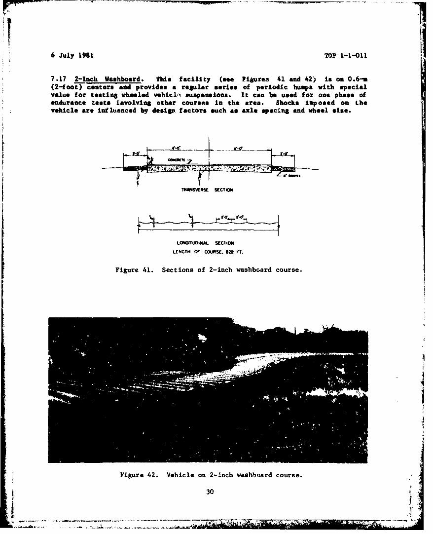
7.17 2-Inch Washboard. This facility (see Figurea 41 and 42) is on 0.6-u(2-foot) centers and provides a regular series of periodic humps with specialvalue for testing wheeled vehicl. suspensions. It can be used for one phase ofendurance tests involving other courses In the area. Shocks Imposed on Lhevehicle are influenced by desi&P factors such as axle spacing and wheel else.
ca"M 7II
1ThNSWVERSE SECTION
LONGITUOINAL S•ECI ION
LENGTH OF COURSE. 022 FT.
Figure 41. Sections of 2-inch washboard course.
I
Figure 42. Vehicle on 2-inch washboard course.
30
-~~~~~~:-. 1- -k ---. -- *-.

6 July '.981 TOP 1-1-011
7.1I6 2- to 4-Inch Radial Washboard. This is laid out on reverse curves in suchI
a manner that the wheels of a test vehicle ore subjected to impacts at variedfrequencies tor any given speed. The course is useful for evaluating "wheelfight" and tendencies toward front-wheel "shimmy" (see Figures 43 and 44).
TRANSVERSE SECTION
WKS I WViS 3, To 4"
~.* ., - * 4
Z COWIETZLONGITUDINAL SECTION
LENGTH OF COURSE. 243 FT.
Figure 43. Sections of radial washboard.
"IT
Figure 44. Radial washboard course.
31
6 July 1981 TOP 1-1-011
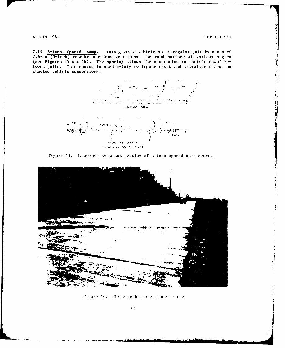
7.19 3-Inch Spaced Bump. This givts a vehicle an irregular jolt by means of7.6-cm (3-inch) rounded sections kLnat cross the road surface at various angles(see Figures 45 and 46). The spacing allows the suspension to "settle down" be-tween jolts. This course is used mp.inly to impose shock and vibration stress onwheeled vehicle suspensions.
.. ~ ... . ... ... . .......... .. .. . . .
Sk:ME TH IC VIEW
1 RAN5V RSI St C I ION
L.EN61 H Of COURSE, 1b4 V I
Figure 45. Isometric view and sect ion of 3-inch spaced bump) coursoS.
..........

6 July 1981 TOP 1-1-011
7.20 6-Inch Washboard.* This Is the most severe of the regular washboard cour-ses, and was designed to evaluate vehicle pitching characteristics (see Figures47 and 48). The pitching is Induced at various speeds. The relatively largeradius of the wave configuration and the 1.8-m intervals ensure that the largerwheels and track pitches ordinarily do a'it bridge the depressions.
TRANSVERSE SECTION
LONGITUDINAL SECTION
LENGTH OF COURSE, 798 FT.
Figure 47. Sections of 6-inch washboard course.
Figure 48. US Roland on 6-inch washboard course.
33
6 July 1981 TOP 1-1-011
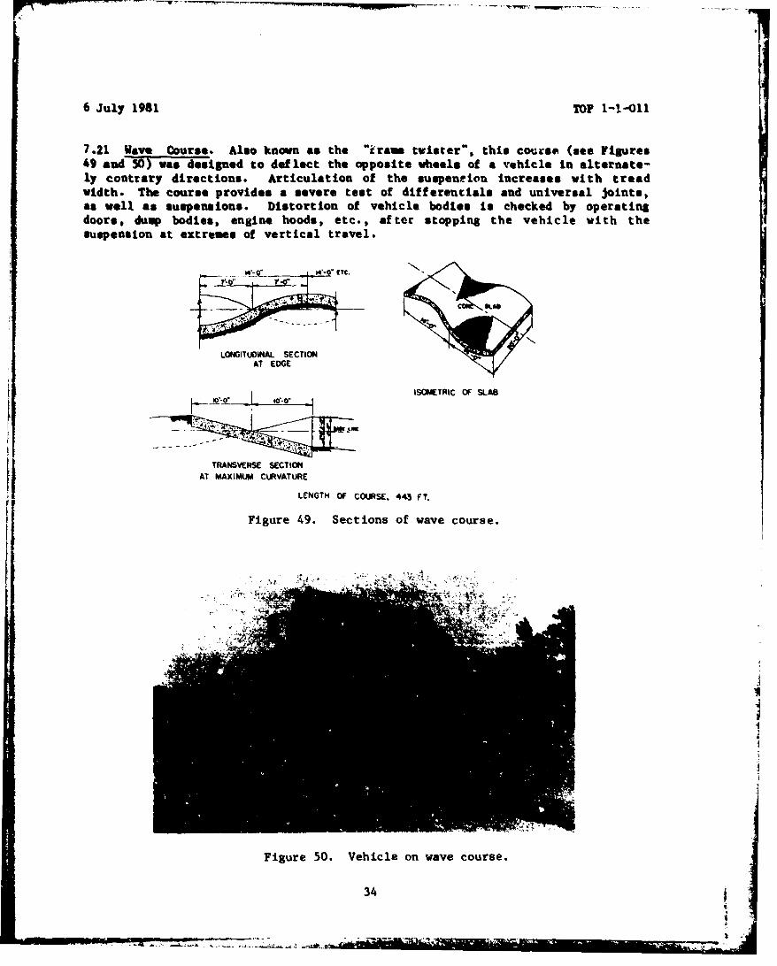
7.21. Wave Course. Also known as the "irams twister", this course (aee Figures49 and 50)3 -wasdesigned to deflect the opposite wheels of a vehicle In alternate-ly contrary directions. Articulation of the suspention Increases with treadwidth. The course provides a severe test of differentials and universal joints,as well as suspensions. Distortion of vehicle bodies is checked by operatingdoors, dump bodies, engine hoods, etc., after stopping the vehicle with thesuspension at extremes of vertical travel.
A,-*" EC.
LONGITUDINAL SECTIONAT EDGE
ISOMETRIC OF SLA13
TRANSVERSE SECTIONAT MAXIMUM CURVATURELI LENGTH OF COURSE. 443 FT.
Figure 49. Sections of wave course.
Figure 50. Vehicle on wave course.
34
6 July 1-9S1 TOP 1-1-oi1
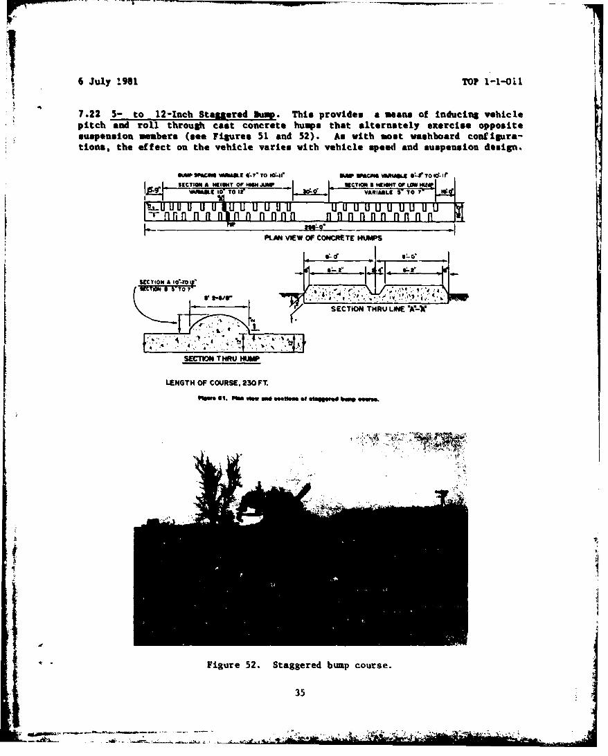
7.22 5-to 12-Inch Staggered Dump. This provides a means of inducing vehiclepitch and roll through cast concrete humps that alternately exercise oppositesuspension members (see Figures 51 and 52). As with isot washboard configure-tions, the effect on the vehicle varies with vehicle speed and suspension design.
VAOX 10cIW Toi VtT -I WUACRIABLE V- TO T' ~
PLAN VIEW OF CONCRETE HUMPS
SECTION THRU LINE OA7-V
4'4
K.SECTIOIN THRIJ HUMP
LENGTH OF COURSE. 230 FT.
IFI," 111. P168 vww Mi 9mehoS of etgs ed 001
Figure 52. Staggered bumup course.
35
6 July 1981 TOP 1-1-Ol
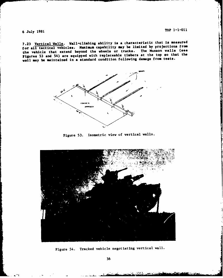
7.23 Vertical Walls. Wall-climbing ability is a characteristic that is maasured
for all tactical vehicles. Maximus capability may be lialted by projections from
the vehicle that extend beyond the wheels or tracks. The Munson walls (see
Figures 53 and 54) are equipped with replaceable timbers at the top so that the
wall may be maintained in a standard condition following damage from tests.
AmAW
Figure 53. Isometric view of vertical walls.
Figure 54. Tracked vehicle negotiating vertical wall.
36

6 July 1981 TOP 1-1-011
7.24 Bridging Device. The bridging requirement f or various types of trackedvehicles is usually specified in the technical characteristics or designspecifications. The bridging device provides an adjustable gap for measuring the
maximum opening that the vehicle can cross -unsupported (see Figures 55 and 56).
AP="
IS3OWTRI( VIEW
Figure 55. Plan and isometric view of bridging device.
Figure 56. 37ridging device.
I 37ý
6 July 1981 TOP 1-1-011
7.25 Ditch Profile. The standard ditch is used to check the adequacy of theangles of approach and departure of tactical vehicles. Tracklayers usuallyrequire rubber tracks for sufficient traction for pulling out of the trench (seeFigures 57 and 58).
SM. "St calm
Figure 57. Plan view and section of ditch profile.
Figure 58. Ditch profile.
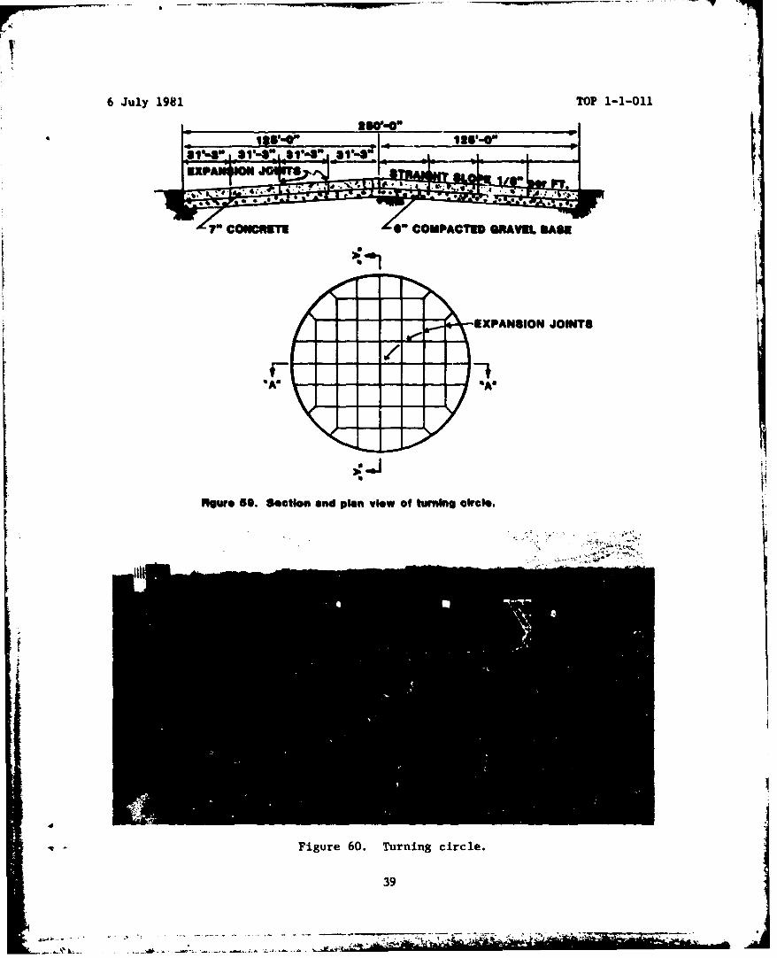
7.26 Turning Circle. This is used for measuring turning diameters on a hardsurface. It is large enough to permit figure-8 turns by the largest vehicles andfor plotting limits of vision (see Figures 59 and 60). It is also used for otheractivities requiring a large and essentially flat concrete surface. An overheadplatform is available at the edge for taking photographs from high angles. Theplatform floor is at a height 7 m 20 cm (24 feet 8 inches) above the circle; thecamera mount, 8 m 23 cm (25 feet 9 inches).
38
6 July 1981 TOP 1-1-011
TO~ ~ ~ CNRT COMPACTED GRAVE sASE
- - - -EXPANSION JOINTS
( 19
Now*e SO. Section and plan vlew of turnkn circle.
Figure 60. Turning circle.
39

6 July 1981 TOP 1-1-011
7.27 Winch Test Pacility. This is used to perform functional tests, e.g.,winch-hclding capability. By means of a cable and pulley arrangement, selectedweights can be liftead vertically while the winch being tested is pulling on acable parallel to the ground.
7.28 Load Vibration Course. This comprises nearly 3.2 km (2 miles) of Munsoncourses (see Figure 61) selected to subject electronic equipment and other sensi-tive loads in wheeled vehicles to various vehicle reactions. The course was ar-ranged to accommodate the standard load vibration test developed in cooperationwith the former Signal Corps Laboratories at Fort Monmouth as a means for deter-mining the ability of electronic units to withstand shock and vibration inspecified vehicles. All road shock and vibration tests now use the automaticdata-acquisition and processing techniques (ADAPT) system. The data aredigitized directly from the test item and transmitted in pulse-coded modulation(PCM) form to a central control station where they are converted by analog-to-digital computer to desired form (tabular and/or graph).
The course is also used for evaluating the portability of other special militaryloads, including those of the Navy and Air Force. The individual courses areparallel with smooth roads for the operation of instrument vehicles.
A ramp-type bump course is employed to impact tracked vehicle pitch in ovder totest turret fire-control components.
IMBEDOED '1 i-SPACED ROCK
BUMPCU~sE 800 FT.S764 FT 20
20 MPH ''.\
WASHBOARDRADIALS ,-123FT. MPH 12OFT I
15M
WAHOAD2MPH % ~ <,~'I ~ nod~oVbaIo~t'I tIURS
-/I/ CO r%7*'EDIST T,/ II / Six-Inch Washboard -7T.
~ I,' 01#ie Block 3940- I4 Imbedded Rock 8004 I RadlolWashboard 243
Three-inch 3pacedwq 764i -Gravel ConnectlngRoods 3241
Total 9786
,,,,-:- ,-, ,S-" ,,
Figure 61. Load vibration test course.40
6 July 1981 TOP 1-1-011
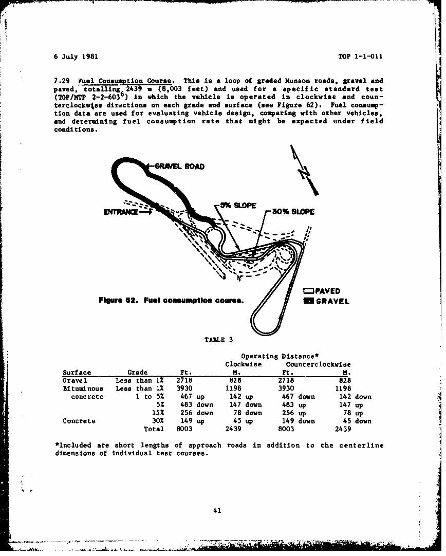
7.29 Fuel Consu'ption Course. This is a loop of graded Munson roads, gravel andpaved, totalling 2439 m (8,003 feet) and used for a specific standard test(TOP/MTP 2-2-6036) in which the vehicle is operated in clockwise and coun-terclockwvse directions on each grade and surface (see Figure 62). Fuel consump-tion data are used for evaluating vehicle design, comparing with other vehicles,and determining fuel consumption rate that might be expected under fieldconditions.
HT~lRI~i9- SLOPESOP
-
Figure 62. Fuel consumptlon course. n GRAVEL
TABLE 3
Operating Distance*Clockwise Counterclockwise
Surface Grade Ft. M. Ft. M.Gravel Less than 1% 2718 828 2718 828Bituminous Less than 1% 3930 1198 3930 1198
concrete 1 to 5% 467 up 142 up 467 down 142 down5% 483 down 147 down 483 up 147 up
15% 256 down 78 down 256 up 78 upConcrete 30% 149 up 45 up 149 down 45 downTotal 8003 2439 8003 2439
*Included are short lengths of approach roads in addition to the centerline
dimensions of individual test courses.
41
- ~7.
6 July 1981 TOP 1-1-011
S. PEIRRYAN TIST ARUA. Perryman adjoins the northwestern boundary of APG, andincludes about 800 hectares (2,000 acres) about 8 km (5 miles) f rom post head-quarters (see Figure 63). Originally devoted to farming, the area is now usedmainly for cross-country testing of vehicles for durability and reliabIlity.Facilities for other tests are also in the area.
Although surface variations due to weather are a desirable feature of mostPerryman courses, changes in course geometry are assessed periodically by a testcourse commnittee that restores the courses to the same severity. Details of theprocedure are contained in TOP 1-1-010. Test course area supervisors also makedaily inspections and maintain an on-site 1og of climatic and course conditions.
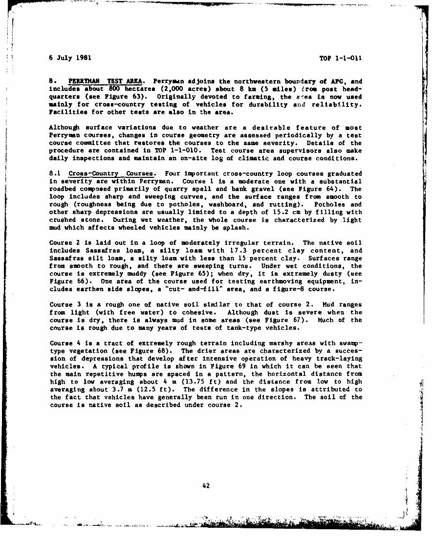
8.1 Cross-Country Courses. Four important cross-country loop courses graduatedin severity are within Perryman. Course 1 is a moderate one with a substantialroadbed composed primarily of quarry spall and bank gravel (see Figure 64). Theloop includes sharp and sweeping curves, and the surface ranges from smooth torough (roughness being due to potholes, washboard, and rutting). Potholes andother sharp depressions are usually limited to a depth of 15.2 cm by filling withcrushed stone. During wet weather, the whole course is characterized by lightmud which affects wheeled vehicles mainly be splash.
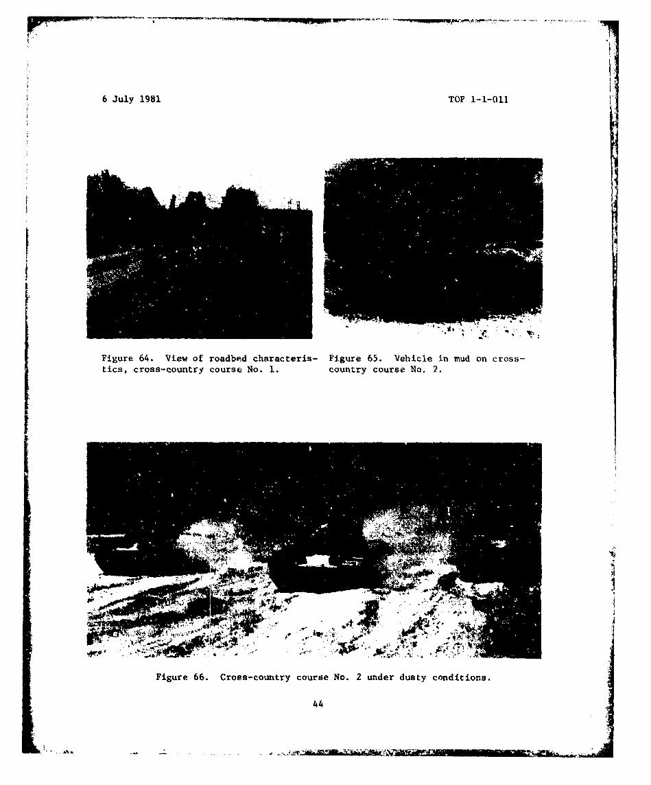
Course 2 is laid out in a loop of moderately irregular terrain. The native soilincludes Sassafras loamu, a silty loam with 17.3 percent clay content, andSassafras silt loam, a silty loam with less than 15 percent clay. Surfaces rangefrom smooth to rough, and there are sweeping turns. Under wet conditions, thecourse is extremely muddy (see Figure 65); when dry, it is extremely dusty (BeeFigure 66). One area of the course used for testing earthmoving equipment, in-cludes earthen side slopes, a "cut- and-fill" area, and a figure-B course.
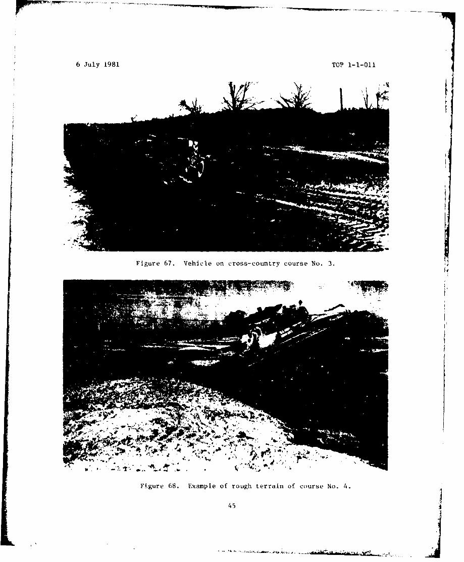
Course 3 is a rough one of native soil similar to that of course 2. Mud rangesfrom light (with free water) to cohesive. Although dust is severe when thecourse is dry, there is always mud in some areas (see Figure 67). Much of thecourse is rough due to many years of tests of tank-type vehicles.
Course 4 is a tract of extremely rough terrain including marshy areas with swamp-type vegetation (see Figure 68). The drier areas are characterized by a succes-sion of depressions that develop af ter intensive operation of heavy track-layingvehicles. A typical profile is ehown in Figure 69 in which it can be seen thatthe main repetitive humps are spaced in a pattern, the horizontal distance fromhigh to low averaging about 4 m (13.75 f t) and the distance from low to highaveraging about 3.7 m (12.5 ft). The difference in the slopes is attributed tothe fact that vehicles have generally been run in one direction. The soil of thecourse is native soil as described under course 2.
42
tL

6 Jilyv 1qg1 TOP 1-1-011
4t1
Figure 63. Aerial view o~f Perrymnan Test Area.
a. No. 1 cross-country course h. Mud bypass course
b. No. 2 cross-country course i. Mud mobility course
c. No. 3 cross-country coorge j. Mobile bridge test facility
d. No. 4 cross-country course k. Deep water fording facility
e. Secondary road A 1. Swamp quarter mobility area
f. Secondary road B mn. Crash barrier
g. 3-mile high speed road n. 3hop area
43
-....... ....j .- -~ . ...~ .s .
6 July 1981 TOP 1-1-011
Figure 64. View of roadbed characteris- Fi~gure 65. Vehicle in mud on cross-tics, cross-country course No. 1. country course No. 2.
IN
Figure 66. Cross-country course No. 2 under dusty conditions.
44
6 J1uly 1981 TOP 1-1-011
Figure 67. Vehicle on cross-country course No. 3.
Figure 68. Example of rough terrain of course No. 4.
45

6 July 1981 TOP 1-1-011
r -pLi r
-I I-SI \ s**
4"
II 3 5 *g S1 -.'•- " a-,
I .... '
nuf
00 a
n 0 .,
•: .' ,
I *.I- "/ "
o p -0 i ., .,
N I•
0pgn I:I*'•_
r,,
(A , 0
.t' -,
(to
00
oet 546
lyr.
6 July 1981 TOP 1-1-0o1
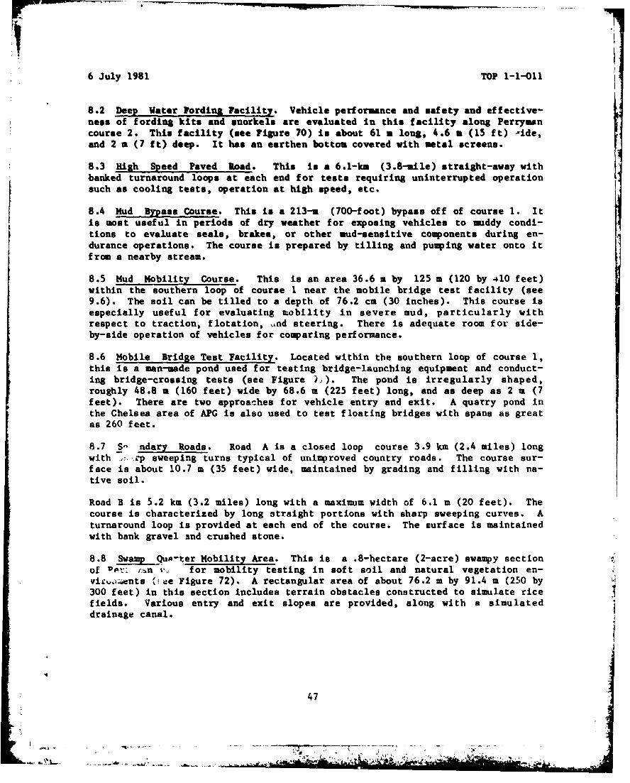
8.2 Deep Water Fording Facility. Vehicle performance and safety and effective-ness of fording kits and snorkels are evaluated in this facility along Perrymancourse 2. This facility (see Figure 70) is about 61 a long, 4.6 a (15 ft) -ide,and 2 a (7 ft) deep. It has an earthen bottom covered with metal screens.
8.3 High Speed Paved Road. This in a 6.1-km (3.8-mile) straight-away withbanked turnaround loops at each end for tests requiring uninterrupted operationsuch as cooling tests, operation at high speed, etc.
8.4 Mud Bypass Course. This is a 213-a (700-foot) bypass off of course 1. It
is most useful in periods of dry weather for exposing vehicles to mddy condi-tions to evaluate seals, brakes, or other mud-sensitive components during en-durance operations. The course is prepared by tilling and pumping water onto itfrom a nearby stream.
8.5 Mud Mobility Course. This is an area 36.6 m by 125 a (120 by 410 feet)within the southern loop of course 1 near the mobile bridge test facility (see9.6). The soil can be tilled to a depth of 76.2 cm (30 inches). This course isespecially useful for evaluating mobility in severe mud, particularly withrespect to traction, flotation, ind steering. There is adequate room for side-by-side operation of vehicles for comparing performance.
8.6 Mobile Bridge Test Facility. Located within the southern loop of course 1,this is a man-made pond used for testing bridge-launching equipment and conduct-ing bridge-crossing tests (see Figure ')). The pond is irregularly shaped,roughly 48.8 m (160 feet) wide by 68.6 a (225 feet) long, and as deep as 2 m (7feet). There are two approaches for vehicle entry and exit. A quarry pond inthe Chelsea area of APG is also used to test floating bridges with spans as greatas 260 feet.
8.7 S- ndary Roads. Road A is a closed loop course 3.9 km (2.4 miles) longwith ,1, rp sweeping turns typical of unimproved country roads. The course sur-face is about 10.7 m (35 feet) wide, maintained by grading and filling with na-tive soil.
Road B is 5.2 km (3.2 miles) long with a maximum width of 6.1 m (20 feet). Thecourse is characterized by long straight portions with sharp sweeping curves. Aturnaround loop is provided at each end of the course. The surface is maintainedwith bank gravel and crushed stone.
8.8 Swamp Qa-ter Mobility Area. This is a .8-hectare (2-acre) swampy sectionof upp: r.n v. for mobility testing in soft soil and natural vegetation en-vii:%,ants ('%,ee Figure 72). A rectangular area of about 76.2 m by 91.4 m (250 by300 feet) in this section includes terrain obstacles constructed to simulate ricefields. Various entry and exit slopes are provided, along with a simulateddrainage canal.
447
Ik47
__* '~*4~ .-- ~ * ~ - - ~ . ~ - . -.-- '--- -- -"-----

6 July 1981 TOP 1-1-011
Figure 70. Vehicle in deep water fording facility.
Figure 71. Ribbon bridge across pond in Chelsea area.
Figure 72. "Rice" field.
48
IA&
6 July 1981 TOP 1-1-011
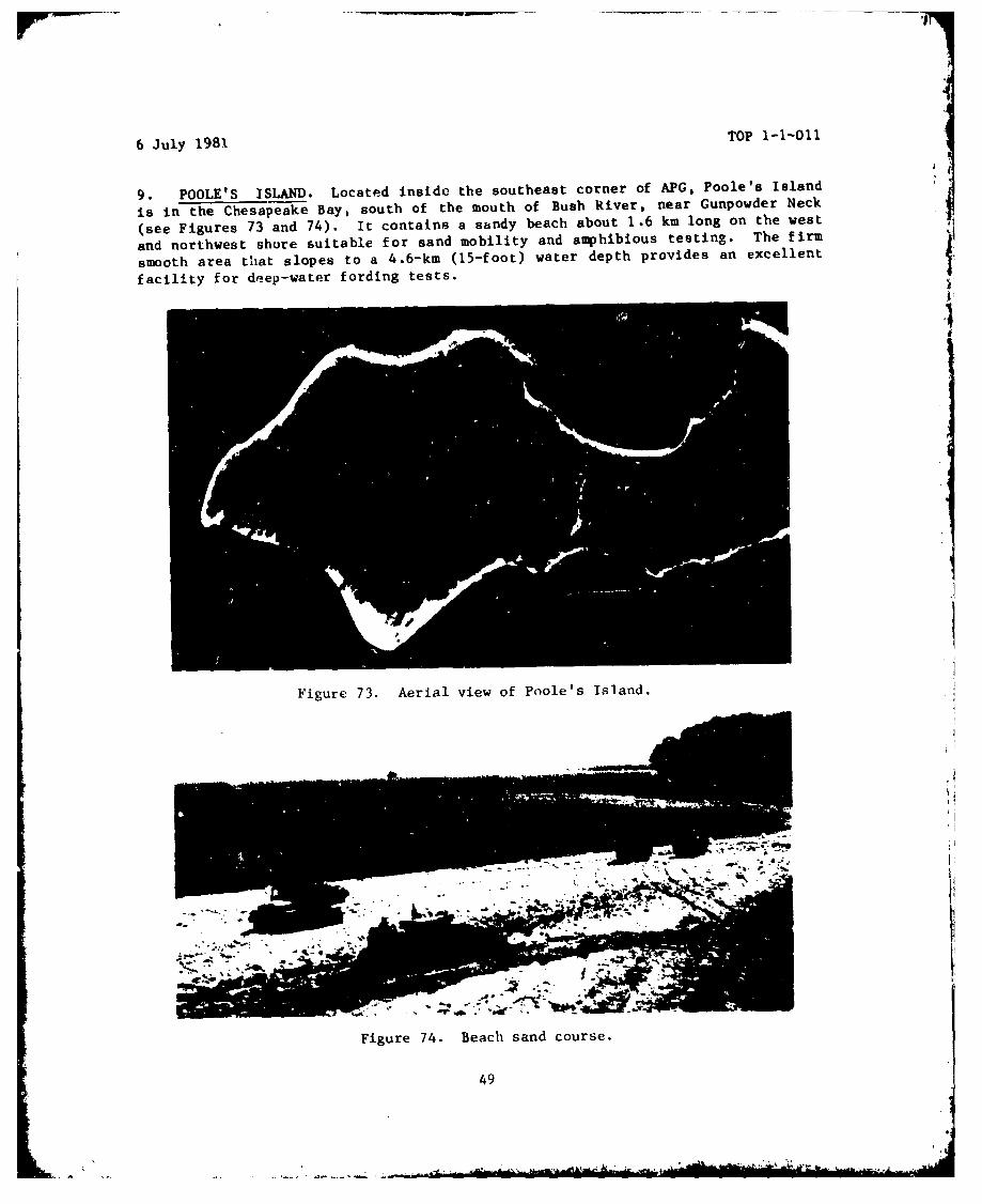
9. POOLE'S ISLAND. Located inside the southeast corner of APG, Poole's Island
is in the Chesapeake Bay, south of the mouth of Bush River, near Gunpowder Neck
(see Figures 73 and 74). It contains a sandy beach about 1.6 km long on the west
and northwest shore suitable for sand mobility and amphibious testing. The firm
smooth area that slopes to a 4.6-km (15-foot) water depth provides an excellent
facility for deep-water fording tests.
Figure 73. Aerial view of Poole's Island.
Figure 74. Beach sand course.
49
- .,4"-_• • -'
6 July 1981 TOP 1-1-011
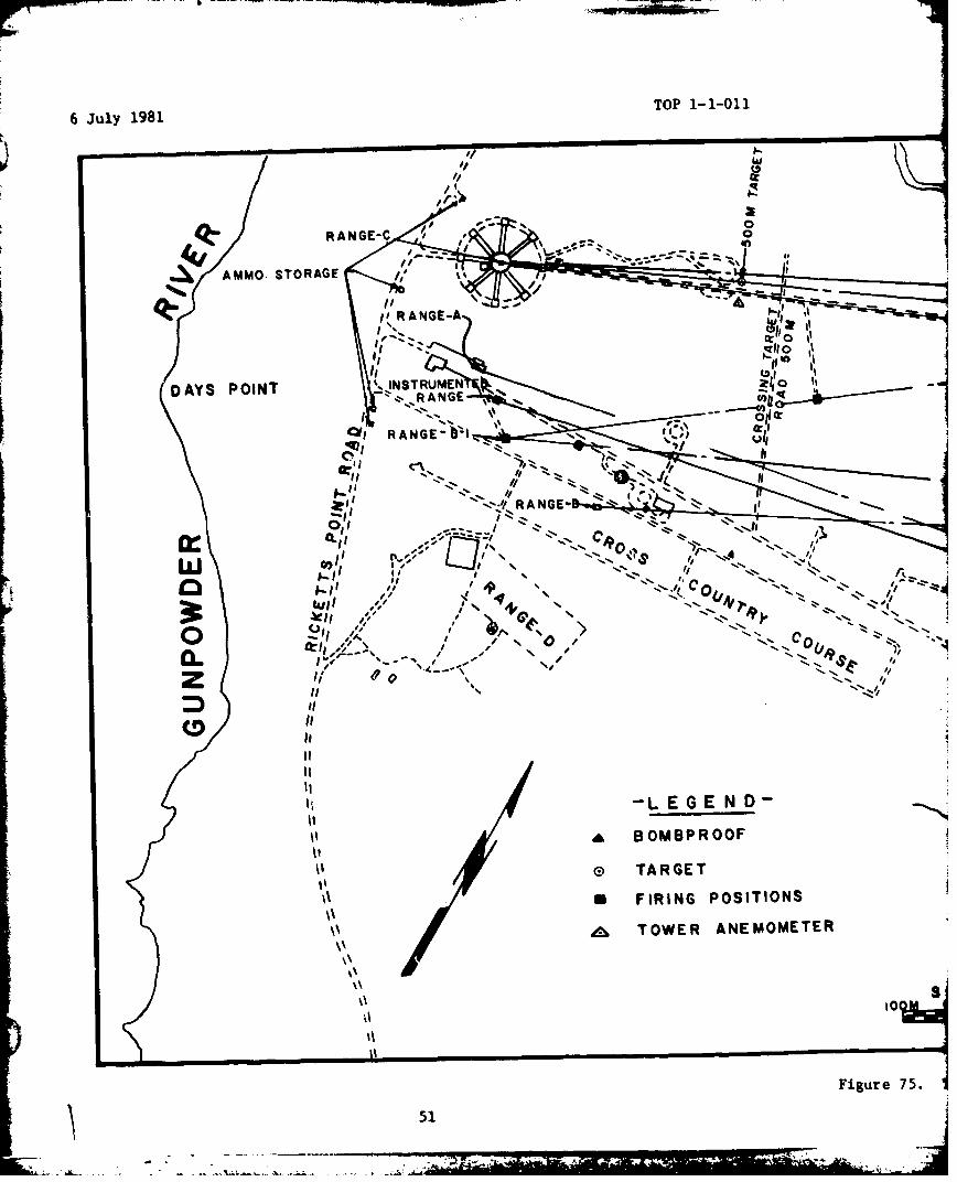
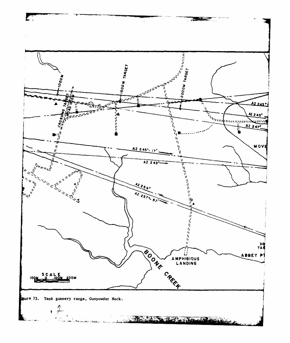
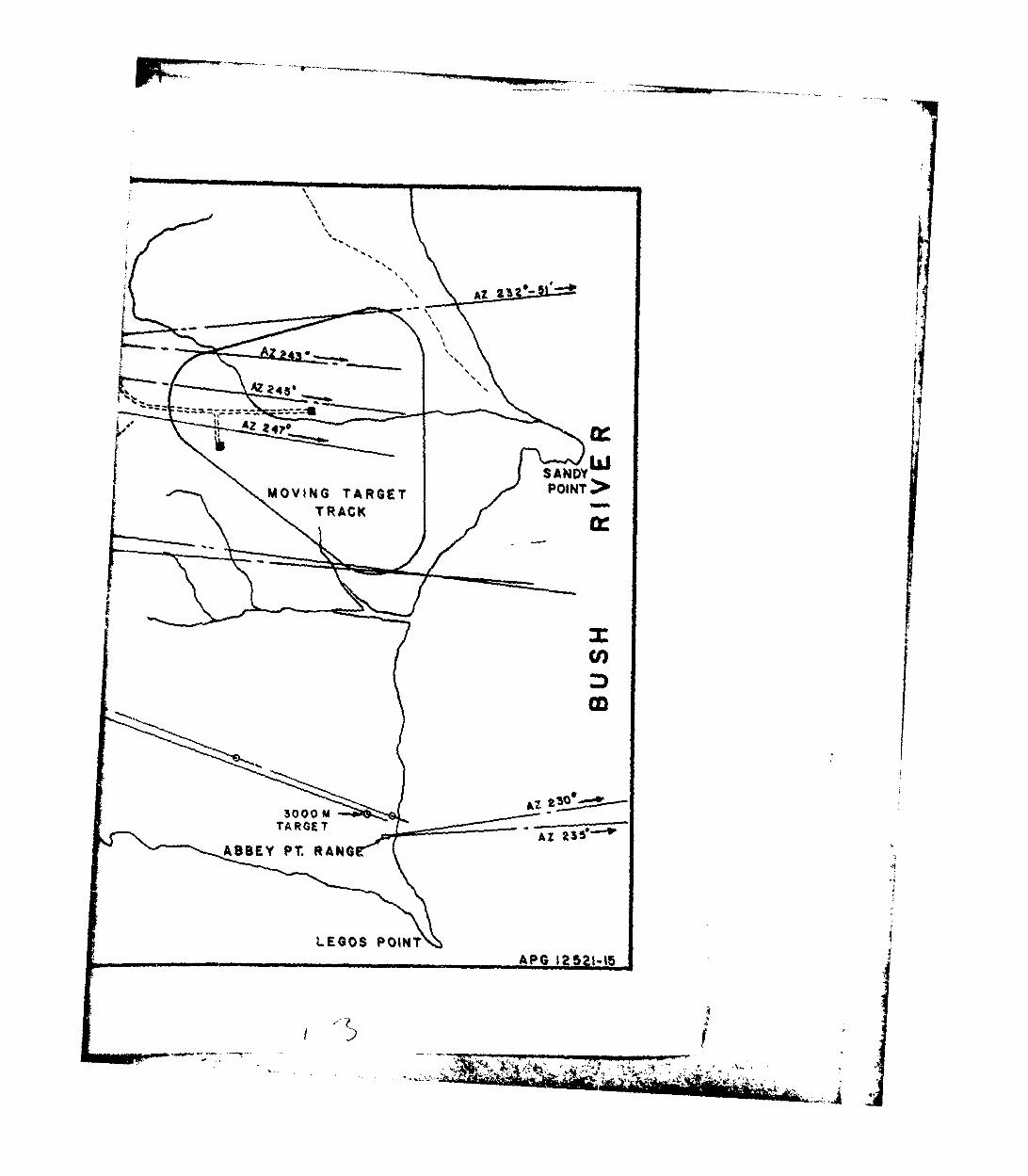
10. TANK GUNNERY RANGES. The testing and evaluation of tank armament is con-ducted on unique firing ranges on Gunpowder Neck and trench warfare (see Figure75). At the H-field area of Gunpowder Neck (see Figure 76), the direct-fireranges are arranged with wide-angle "safety fans" with line-of-sight targets asfar away as 3000 meters. For specialized long-range firing, a range of 5000meters (partly over water) is available. Special firing slopes (15 percent up,30 percent down, and various combination slopes up to 20%) permit firing at maxi-mum gun elevation and depression, as well as over a variety of vehicle attitudes.Supporting facilities include a four-bay maintenance shop, ammunition magazines,wind velocity instrumentation, and communications and other equipment. Thetarget-simulation facility at the C-field area of Gunpowder Neck is used for gunlaying, tracking, and fire control system accuracy/performance tests. I' employsa computer-controlled laser beam on a large screen mounted inside a building.
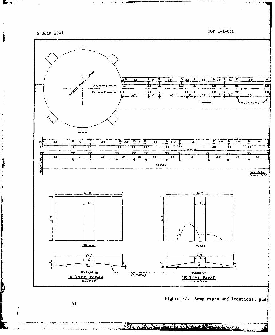
Standardized cross-country courses and test conditions (e.g., bump) are availablefor comparative performance testing of tank turret-stabilized fire control sys-tems (see Figure 77). A cross-country course of about 1.6 km long is in the areafor determining durability characteristics of gunnery systems during vehicleoperation.
A 6- by 6-m (20- by 20-foot) moving target facility (see Figure 78) has speeds asgreat as 56 km (35 miles) per hour. On the zig-zag course (range C), remote con-trols and a 2-km (1-1/4-mile) triangular railroad layout are used to alter thespeed and orientation of the moving target to the line of fire. The moving tar-get is used to measure accuracy of fire for tank turrets, including thoseequipped with hyper-velocity guns or guided missiles. A specially instrumentedrange is installed for use with tank-fired missiles (see Figure 79).
In addition, the H-field ranges are equipped with video scoring instrumentationto remotely record target impacts, by means of a fully automated meteorologicalstation. Other telemetry and data-processing instrumentation are available torecord and reduce date obtained from monitoring on-board vehicular nquipment suchas gun sight optics, ballistics computer output, rangefinder readings, and maingun aimpoint.
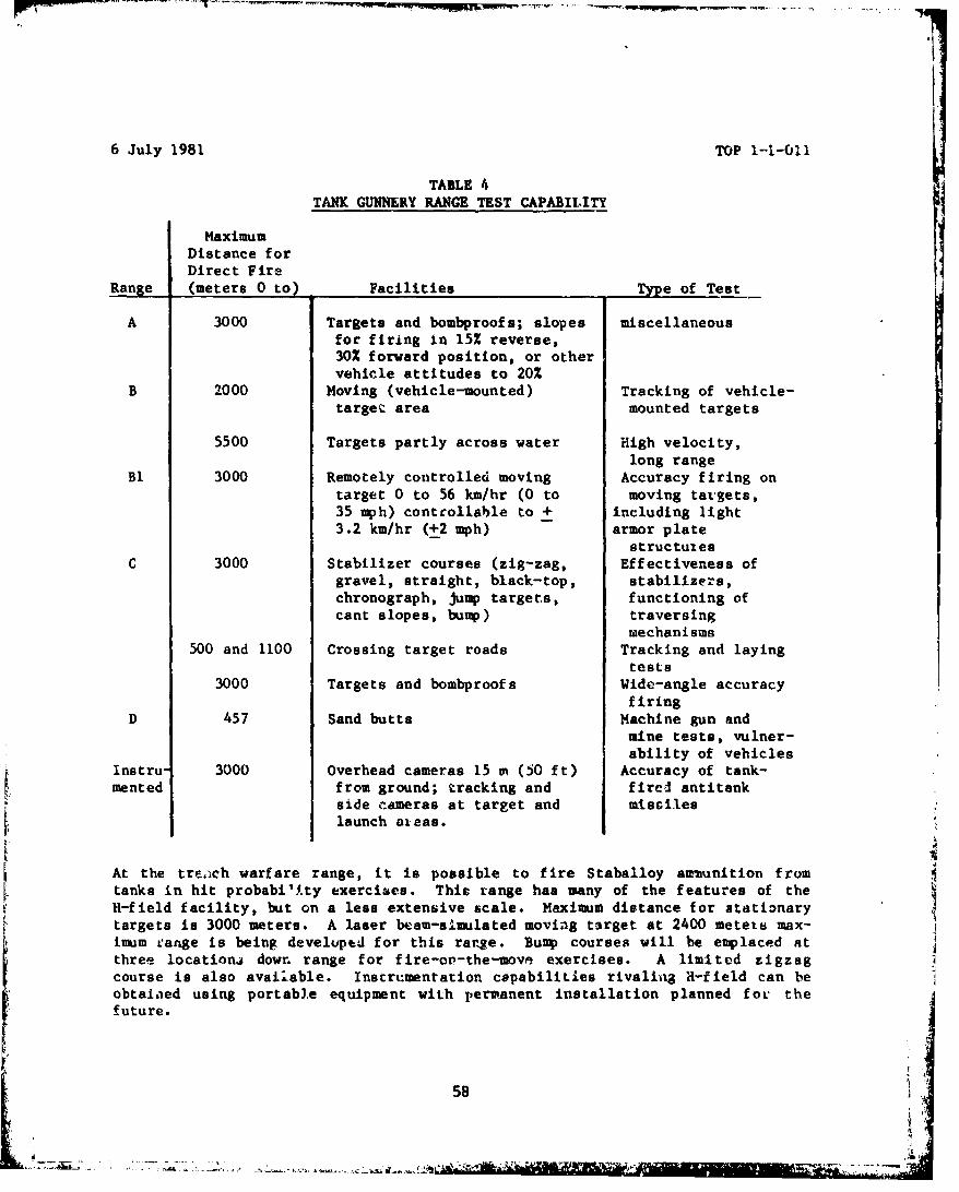
Testing capabilities at the principal ranges are summarized in Table 4.
so
50
6 July 1981 TOP 1-1-011
RANGE-C 0'
AMMO. STORAGE
DAYS POINT YINSTRUMEN a
oil R ANGE RA GI
it'l I. cl' ý, X..R, A' N p 111,N ý
0.111
z~ o,
It
-LEGEND-
SBOMBPROOFIt
0 TARGETU1 FIRING POSITIONS
STOWER ANEMOMETER
10
Figure 75.
51
11111I 114
P6,,
A~ ,.
56 // I
It mooAZo 45---
IITAI
0 AMPIBOU
re 75. Tank gunnery range, Gunpowder Neck.
AZA
AZ 243
2 2~ 470

53 3
..... ....
6 July 1981 TOP 1-1-011
r,- -r -- -r -- --- r - - iT.e4' Lme a, - .f - U0- ru- Evf ru- rUU U U-i
At ~-4**
t5 is' -J7IT-1-11ri0-'~ '-I' i-ri ru-i ri r-ri i-ri
'4 -d -
101
.L~bMA~*M~' 81 )L~I-IOE5 - - I.~I~higA
A ~ ~UAP CA) *~ W-01A
Figure 77. Bump types and locations, gun1
(5

•li Li ii l lil .l J 1. 1 . - I I III
fa,,n SO " I j 'AS
1 fin rri •rn frl F- -- !I:
.__ _. _____-_• __'.__.......I _ -t------ a"7t;nnv vu• " J utJ . ....L UtU :I EDI LIU
5LLI .ZO'
,1
ocations, gun stabilizer test course.
S-* A- ,

6 July 1981 TOP 1-1-011
Figure 78. Moving target facility.
Figure 79,. Tank missile firing setup.
57
6 July 1981 TOP 1-1-011
TABLE 4TANK GUNNERY RANGE TEST CAPABILITY
MaximumDistance forDirect Fire
Range (meters 0 to) Facilities Type of Test
A 3000 Targets and bombproofs; slopes miscellaneousfor firing in 15% reverse,30% forward position, or othervehicle attitudes to 20%
B 2000 Moving (vehicle-mounted) Tracking of vehicle-target area mounted targets
5500 Targets partly across water High velocity,long range
B1 3000 Remotely controlled moving Accuracy firing ontarget 0 to 56 km/hr (0 to moving targets,35 mph) contcollable to + including light3.2 km/hr (+2 mph) armor plate
structutesC 3000 Stabilizer courses (zig-zag, Effectiveness of
gravel, straight, black-top, stabilizers,chronograph, jump targets, functioning ofcant slopes, bump) traversing
mechanisms500 and 1100 Crossing target roads Tracking and laying
tests3000 Targets and bombproof s Wide-angle accuracy
firingD 457 Sand butts Machine gun and
mine tests, vulner-ability of vehicles
Instru- 3000 Overhead cameras 15 m (50 ft) Accuracy of tank-mented from ground; tracking and fircd antitank
side cameras at target and miscileslaunch areas.
At the tre,6 ,ch warfare range, it is possible to fire Staballoy ammunition fromtanks in hit probabi'1ty exercises. Thic range has many of the features of theH-field facility, but on a less extensive scale. Maximum distance for atationarytargets is 3000 meters. A laser b+.am-s'.mulated moving target at 2400 meters max-imum eange is being develuped for this range. Bump courses will be emplaced atthree locationa down range for fire-or-the-move exercises. A limited zigzagcourse is also available. Instri.mentation capabilities rivaling H-field can beobtained using portable equipment with perwanent installation planned for the
future.
58

6 July 1981 TOP 1-1-011
Trench warfrre is also used for longer distance nonfiring target surveillance andobservation exercises to evaluate combat vehicle night sights. Its large openarea with undulating terrain can accommodate targets as far as 4000 meters fromthe viewing vehicle.
The motion of the maneuvering target (target simulation facility) is emulated bya moving image projected onto a screen in flont of the tank. A small CW HeNelaser is now used as the projection light source, and a scanning mirror is usedto control the movement of the target image. A digital minicomputer is used tocontrol mirror and target movement, calibration, fire commands sent to the gun-ner, and generation of documentation words to be recorded with the data. Thecomputer requests input from the test director and then controls all testingautomatically.
Tracking data are generated by two gated TV systems with input from a videocamera boresighted with the tank gun (to collect lead angle and tracking data)and another video camera in the sight (to collect gunner tracking data). Thesesystems are video digitizers that output constantly updated error signals equalto the target's azimuth and elevation deflections in the field of view of thevideo cameras. These systems essentially accomplish real time automatic filmreading with video input, and error signal output recorded directly on magnetictape. Video recorders provide video documentation of the gated TV tracking data,and monitors allow the test director real time monitoring of the video data.
11. TILT TABLE. This is adjacent to a shop building near Mulberry Point. Thissteel table, 0.3 m (1 foot) high, is used to determine tipping angles ofvehicles, most cosmonly small warehouse and rough terrain forklifts. Two5-ton-capacity manual chain hoists at the rear of the table regulate its slopefrom 0 to 40 percent. The overall surface dimensions of the table are 3.8 m (12feet 6 inches) wide by 3.7 m (12 feet) long (the 3.7-m edge being the tippingedge).
Recommended changes of this publication should be forwardedto Commander, US Army Test and Evaluation Command, ATTN:DRSTE-AD-K, Aberdeea Proving Ground, Md. 21005. Technicalinformation may be obtained from the preparing activity:Commander, US Army Aberdeen Proving Ground, ATTN:STEAP-MT-M, Aberdeen Proving Ground, Md. 21005. Additionalcopies are available from the Defense Technical InformationCenter, Cameron Station, Alexandria, Va. 22314. This docu-ment is identified by the accession number (AD No.) printedon the first page.
59
wNo
6 July 1981 TOP 1-1-011
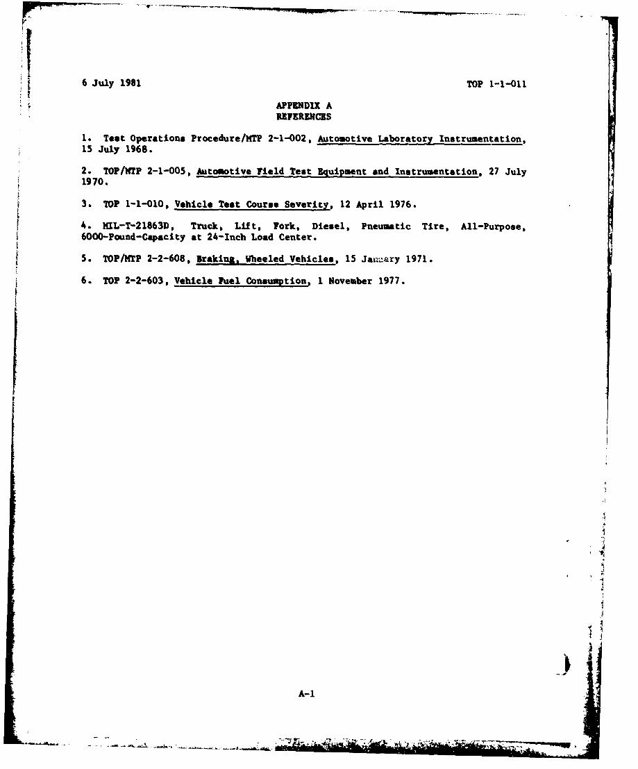
APPENDIX AlnFI•RE CES
1. Test Operations Procedure/MTP 2-1-002, Automotive Laboratory Instrumentation,15 July 1968.
2. TOP/KTP 2-1-005, Automotive Field Test Equipment and Instrumentation, 27 July
1970.
3. TOP 1-1-010, Vehicle Test Course Severity, 12 April 1976.
4. MIL-T-21863D, Truck, Lift, Fork, Diesel, Pneumatic Tire, All-Purpose,6000-Pound-Capacity at 24-Inch Load Center.
5. TOP/HTP 2-2-608, Braking, Wheeled Vehicles, 15 Jav.&ry 1971.
6. TOP 2-2-603, Vehicle Fuel Consumption, 1 November 1977.
A-1
r -. ','