lcls injector experiments feng zhou ard thanks brachmann, emma, gilevich, huang, ding, and dowell...
TRANSCRIPT
LCLSInjector experiments
Feng ZhouARD
Thanks Brachmann, Emma, Gilevich, Huang, Ding, and Dowell for great contributions and fruitful discussions

Contents
• Injector experiments at LCLS– Spatial laser Gaussian-cut – Thermal emittance vs. QE– Cathode R&D
• LCLS operations
Spatial Gaussian-cut experiment
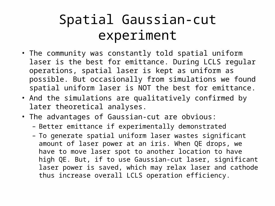
• The community was constantly told spatial uniform laser is the best for emittance. During LCLS regular operations, spatial laser is kept as uniform as possible. But occasionally from simulations we found spatial uniform laser is NOT the best for emittance.
• And the simulations are qualitatively confirmed by later theoretical analyses.
• The advantages of Gaussian-cut are obvious:– Better emittance if experimentally demonstrated– To generate spatial uniform laser wastes significant amount of
laser power at an iris. When QE drops, we have to move laser spot to another location to have high QE. But, if to use Gaussian-cut laser, significant laser power is saved, which may relax laser and cathode thus increase overall LCLS operation efficiency.
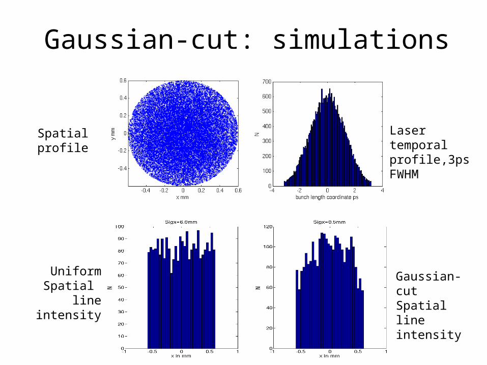
Gaussian-cut: simulations
Gaussian-cut Spatial line intensity
Laser temporal profile,3ps FWHM
Spatial profile
Uniform Spatial
line intensity

Simulated emittances

Theory
(Z. Huang)
x/r=0.5
x/r=1.0
x/r=10
• For the Gaussian distributions in x/y/z, an exact solution of transverse space charge field can be obtained. The calculation is done with truncated spatial Gaussian and pure temporal Gaussian (conditions same as simulations).
• Assume r=0.6mm, space charge linearity with x=0.6mm is better than both x=6mm (uniform) and x=0.3mm at -0.6<x<0.6mm

Drive laser setup• Two spatial laser profiles for 250 pC:
– Uniform-like for LCLS regular operation to have ‘5.8%’ of transmission through C_iris
– Gaussian-cut by adjusting telescope upstream of C_iris to have ‘10.2%’ of transmission through C_iris
• Laser power/QE is critical for the LCLS operation, with QE of 03/02/2011:– 5.8% transmission 42% of max. laser energy needed (uniform-like)– 10.2% transmission 22% of max. laser energy needed (Gaussian-cut)
5.8% case – 5.8% of transmission through C_iris
10.2% case – 10.2% of transmission through C_iris
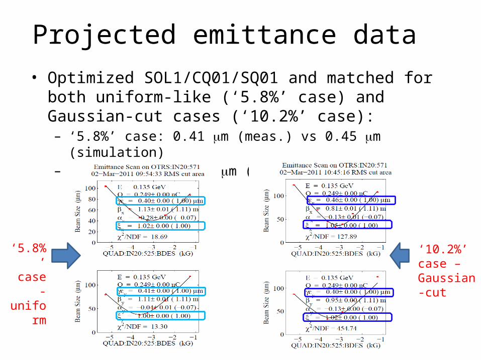
Projected emittance data • Optimized SOL1/CQ01/SQ01 and matched for both uniform-
like (‘5.8%’ case) and Gaussian-cut cases (‘10.2%’ case):– ‘5.8%’ case: 0.41 m (meas.) vs 0.45 m (simulation)– ‘10.2%’ case: 0.43 m (meas.) vs 0.48 m (simulation)
‘5.8%’ case -
uniform
‘10.2%’ case – Gaussian-cut

Slice emittance data
‘5.8%’ case –
uniform
’10.2%’ case – Gaussian-cut
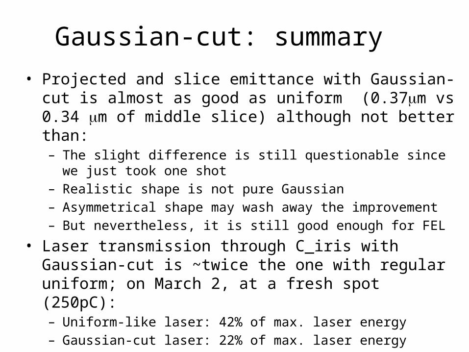
Gaussian-cut: summary • Projected and slice emittance with Gaussian-cut is almost as
good as uniform (0.37m vs 0.34 m of middle slice) although not better than:– The slight difference is still questionable since we just took one shot– Realistic shape is not pure Gaussian– Asymmetrical shape may wash away the improvement– But nevertheless, it is still good enough for FEL
• Laser transmission through C_iris with Gaussian-cut is ~twice the one with regular uniform; on March 2, at a fresh spot (250pC):– Uniform-like laser: 42% of max. laser energy – Gaussian-cut laser: 22% of max. laser energy
• Next MD:– Check the sensitivity of profile asymmetry on emittance – Measure FEL parameters and set up for operation if justified.
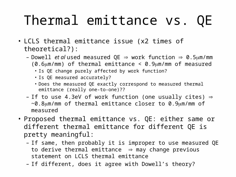
Thermal emittance vs. QE• LCLS thermal emittance issue (x2 times of theoretical?):
– Dowell et al used measured QE work function 0.5m/mm (0.6m/mm) of thermal emittance < 0.9m/mm of measured
• Is QE change purely affected by work function? • Is QE measured accurately?• Does the measured QE exactly correspond to measured thermal emittance
(really one-to-one)??
– If to use 4.3eV of work function (one usually cites) ~0.8m/mm of thermal emittance closer to 0.9m/mm of measured
• Proposed thermal emittance vs. QE: either same or different thermal emittance for different QE is pretty meaningful:– If same, then probably it is improper to use measured QE to derive
thermal emittance may change previous statement on LCLS thermal emittance
– If different, does it agree with Dowell’s theory?
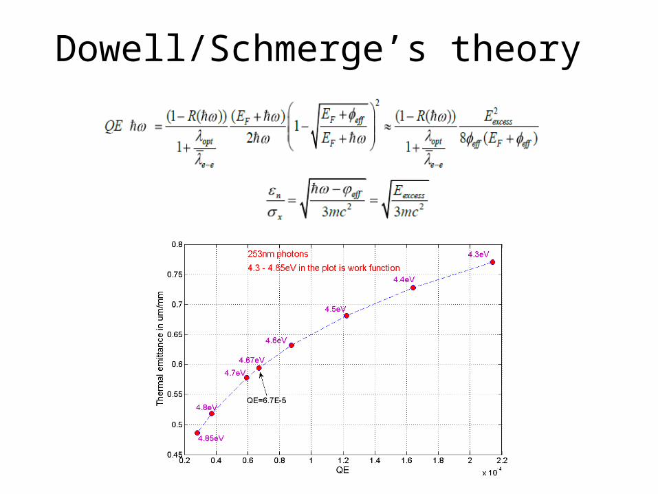
Dowell/Schmerge’s theory
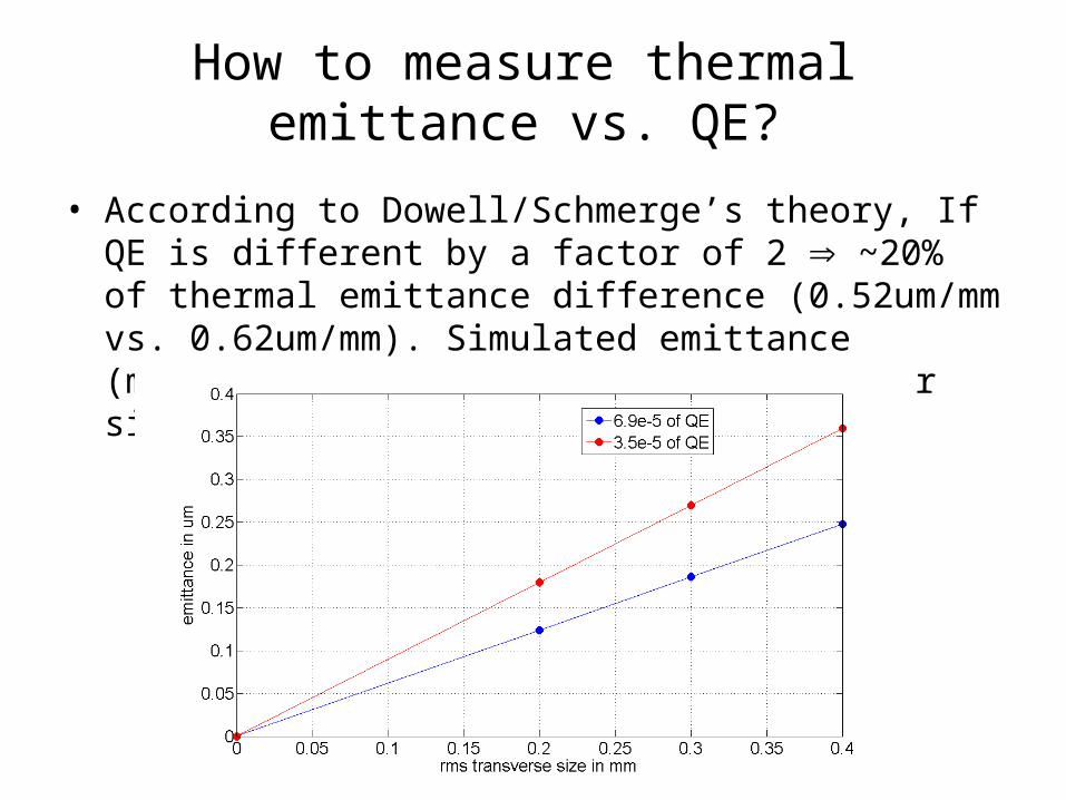
• According to Dowell/Schmerge’s theory, If QE is different by a factor of 2 ~20% of thermal emittance difference (0.52um/mm vs. 0.62um/mm). Simulated emittance (middle slice) vs. rms transverse laser size:
How to measure thermal emittance vs. QE?
How to measure thermal emittance vs. QE (con’t)?
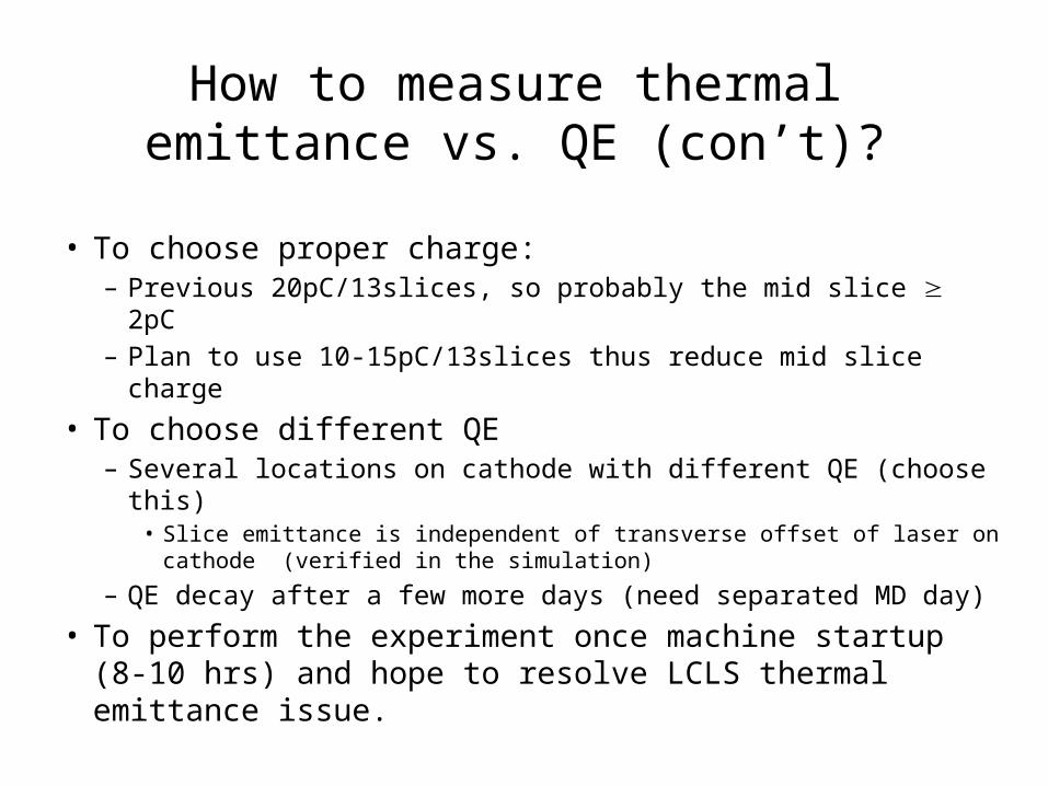
• To choose proper charge: – Previous 20pC/13slices, so probably the mid slice 2pC– Plan to use 10-15pC/13slices thus reduce mid slice charge
• To choose different QE– Several locations on cathode with different QE (choose this)
• Slice emittance is independent of transverse offset of laser on cathode (verified in the simulation)
– QE decay after a few more days (need separated MD day)
• To perform the experiment once machine startup (8-10 hrs) and hope to resolve LCLS thermal emittance issue.
LCLS cathode R&D (Led by Brachmann)
• Cathode R&D is being performed by Brachmann, Steffen, and me:– Setup test chamber and relevant data acquisitions– Test plasma cleaning sources, and– Clean cathodes in test chamber– Test cathode transfer to mimic practical cathode
transfer condition • Results, issues and near-term plans
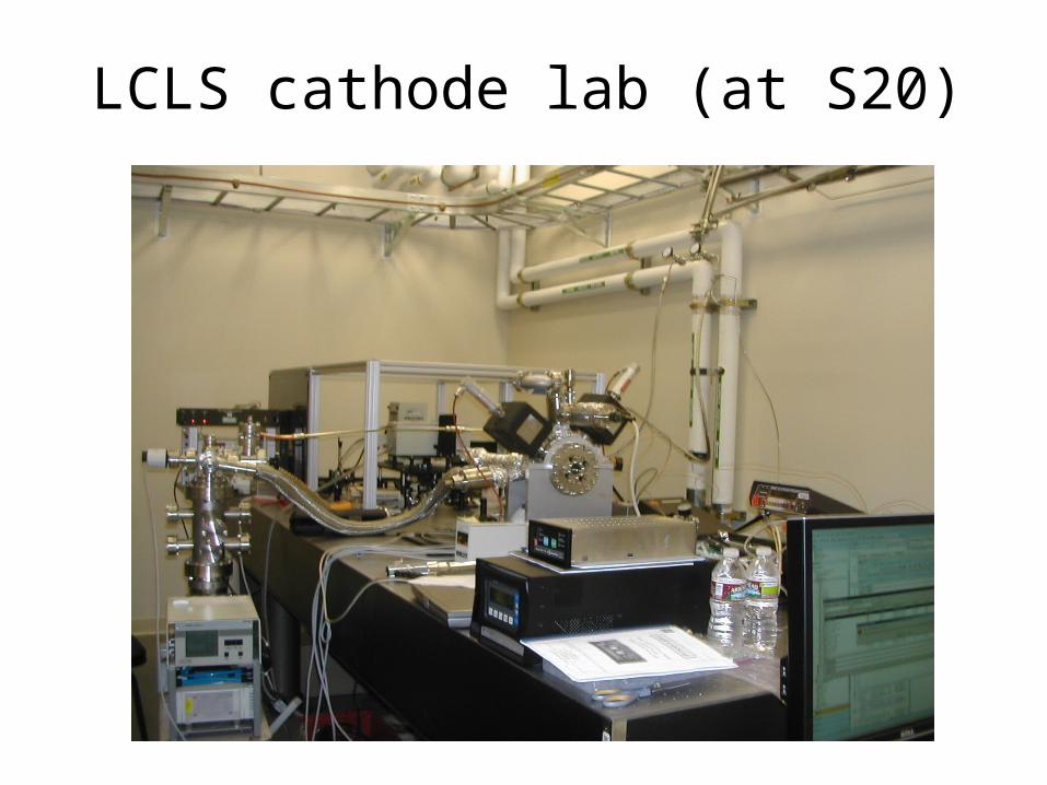
LCLS cathode lab (at S20)

Hydrogen cleaning
• The carbon from disassociated hydrocarbons is then attracted to cathode, which may increase work function and thus reduce QE.
• Hydrogen cleaning can remove hydrogen. The products of CO2, CO, and H2O can be removed by roughing pump.
• We have two plasma source working at 70mT and one working at high vacuum 1E-8 to 1E-9 Torr. So far we tested the ones working at 70mT.
Initial results, issues, and plans• Before cleaning most cathodes’ QE died. After cleaning, QE can be up to
2e-4, and can stay constant for many days.• When exposed to air for ~1 minute during cathode transfer, QE drops by an
order of magnitude, which indicate cleaning must be at gun in-situ. • Near-term plans (probably my personal view) after this cathode crisis is
solved:– First to make the cleaning source working at 70mT going:
• Develop solid recipes in the current test chamber • Then test it at NLCTA or GTF? Maybe temporary and may not get recipes to have best QE due
to lack of online diagnostics when cleaning. • We should build a permanent LCLS gun-like test chamber with extension tube (just exactly
same as in-situ cleaning setup in the current gun) and develop the recipes which can be solidly applied into LCLS gun
– Next to make the cleaning source working at 1e-9 Torr going:• Develop solid recipes in the current test chamber• Develop recipes in the LCLS-like test chamber • Confirm the recipes at NLCTA or GTF?• Install into the LCLS gun and then can fresh QE on-line - all problems solved and one cathode
can survive forever.
LCLS operations
• Participate LCLS operations, and start program deputy (PD) shifts
• Modified some operation software Matlab GUI, and will be tested when machine startup