lavina 13x/13x-hv user manual - amazon s3 · the lavina® 13x machine is intended for grinding,...
TRANSCRIPT

LAVINA® 13X/13X-HV User Manual
Tech Support Line: 800-987-8403 | www.superabrasive.com | [email protected]
Superabrasive User Manual Original Language Lavina®13X/Lavina®13X-HV 2/2015
2
Superabrasive User Manual Original Language Lavina®13X/Lavina®13X-HV 2/2015
3
WARRANTYANDRETURNSWARRANTY POLICY FOR LAVINA® X MACHINES A warranty card must be submitted to Superabrasive within 30 days of purchase in order for the foregoing warranty to apply.
You can either mail a hard copy of the warranty card or submit it electronically - see page 2. Superabrasive warrants, from the time of delivery and receipt by the original customer, new and unused products sold by Superabrasive or Superabrasive-appointed distributors or dealers. Goods shall be free from defects in materials and workmanship. Superabrasive or a Superabrasive-appointed repair facility shall either replace or repair any defects in the Goods resulting from faulty design, materials, or workmanship. Products repaired or replaced during the warranty period shall be covered by the foregoing warranty for the remainder of the original warranty period, or ninety (90) days from date of the repair or shipment of the replacement, whichever is longer. Spare parts for repair will be either new or equivalent to new.
Warranty period shall be 2 years from the time of delivery and receipt by the original customer, or 600 operating hours on the machine - whichever occurs first. Superabrasive will cover the shipping charges for the transportation of the machine to Superabrasive (or an approved repair facility) and back to the customer (within the contiguous 48 States) in the event that the damage occurs and is reported within 200 operating hours .Shipping charges, if covered by Superabrasive, must be agreed upon in advance and approved by Superabrasive. Thereafter, the customer will have to cover the shipping charges to Superabrasive and back. Superabrasive will not warranty Goods after a period of 2 years from the time of delivery and receipt by the original customer, or 600 operating hours on the machine - whichever occurs first. Superabrasive shall not be liable for any defects that are caused by circumstances that occur after the Goods have been delivered and whilst the Goods are in the possession of the purchaser. Furthermore, the warranty does not include normal wear and tear or deterioration. Wear parts are not warranted. Superabrasive is not liable for defects arising out of use of non-OEM parts.
The Warranty is void if the purchaser has not followed the maintenance plan stipulated by the machine’s manual and warranty card. The warranty is void if the purchaser repairs said Goods himself, or if repairs are conducted by a repair facility that is not approved by Superabrasive. Superabrasive’s liability does not cover defects which are caused by faulty maintenance, incorrect operation, faulty repair by the purchaser, or by alterations conducted without Superabrasive’s prior written consent. The same applies to any alterations of the Goods or services performed by another party other than Superabrasive, a Superabrasive-appointed distributor, or a Superabrasive-approved repair facility. The warranty is not applicable on a defect that arises due to tools or parts that are not original to Superabrasive. Replaced defective parts shall be placed at Superabrasive’s disposal and shall become property of Superabrasive. If such defective parts are replaced within the warranty period, the shipping charges will be covered by Superabrasive. In warranty complaint cases, when no defects are found for which Superabrasive is liable, Superabrasive shall be entitled to compensation for the labor, material cost, and shipping charges, incurred by Superabrasive as as a result of the complaint.
The warranty herein is non-transferable, and only applies to the original owner or purchaser of the machine.
RETURN POLICY FOR LAVINA® X MACHINES
The Lavina® X machines may be returned, subject to the following terms: In no case, a machine is to be returned to Superabrasive Inc. for credit or repair without prior authorization. Please contact Superabrasive Inc. or your local distributor for an authorization and issuance of a return authorization number. This number along with the serial number of the machine must be included on all packages and correspondence. Machines returned without prior authorization will remain property of the sender and Superabrasive Inc. will not be responsible for them. No machines will be credited after 90 days from the date of invoice.
All returns must be shipped freight prepaid. Returned machines may be exchanged for other equipment or parts of equal dollar value. If machines are not exchanged, they are subject to a fifteen percent (15%) restocking fee.
Superabrasive User Manual Original Language Lavina®13X/Lavina®13X-HV 2/2015
4
WARRANTYANDRETURNS................................3 WARRANTY POLICY FOR LAVINA® X MACHINES ........................... 3
RETURN POLICY FOR LAVINA® X MACHINES ................................. 3
1. GENERAL INFORMATION.....................................5 Manufacturer ................................................................................. 5
General Description ....................................................................... 5
Machine characteristics ................................................................. 5
MAIN DESIGN................................................................................. 5
Environmental Conditions ............................................................. 5
Electrical Connection ..................................................................... 5
Vacuum Connection ....................................................................... 6
Technical Data ............................................................................... 6
VIBRATIONS ................................................................................... 6
SONOROUS EMISSIONS ................................................................. 6
LABEL DATA ................................................................................... 6
Customer Service ........................................................................... 6
2. SAFETY INSTRUCTION...........................................7 Recommended Use ........................................................................ 7
Prohibited Use ............................................................................... 7
Preparation for work ..................................................................... 7
Protection Devices ......................................................................... 7
Arrest Functions ............................................................................. 7
Safe Use ......................................................................................... 7
Residual Risks ................................................................................ 7
Before You Begin ........................................................................... 7
Operating Machine ........................................................................ 7
After Work is completed ................................................................ 7
The Work Area ............................................................................... 7
PERSONAL PROTECTIVE Equipment (ppe) ...................................... 7
Operator ........................................................................................ 8
3. OPERATION............................................................8 Preliminary Controls ...................................................................... 8
Mounting Tools .............................................................................. 8
leveling after mounting the tool .................................................... 9
Adjusting handle ............................................................................ 9
Tool protecting guard .................................................................... 9
the Control Board ........................................................................ 10
Starting the Machine ................................................................... 10
Operating the Machine ................................................................ 10
Stopping the Machine .................................................................. 10
4. TOOLS AND ACCESSORIES................................11 WEIGHTS ...................................................................................... 11
Tool holder key ............................................................................ 11
Foam Plate ................................................................................... 11
Security plate for Quickchange pads ............................................ 11
5. POPULAR TOOLS.................................................12
6. MAINTENANCE AND INSPECTION....................13 Cleaning ...................................................................................... 13
Check Daily .................................................................................. 13
Check and replace after the first 15 Working Hours .................... 13
Check Every 200 Working Hours .................................................. 13
Check Every 500 Working Hours .................................................. 13
Vacuum ....................................................................................... 13
Mechanical Parts ......................................................................... 13
Electrical System ......................................................................... 13
Lavina® 13X Electrical schemes with YASKAWA Inverter 200‐240 Volt
.................................................................................................... 14
LAVINA® 13X ELECTRICAL SCHEMES YASKAWA CONNECTION MAIN
CIRCUIT TERMINALS .................................................................... 14
Lavina® 13X‐HV Electrical schemes with YASKAWA Inverter 440‐480 Volt
.................................................................................................... 15
LAVINA® 13X‐HV ELECTRICAL SCHEMES YASKAWA CONNECTION MAIN
CIRCUIT TERMINALS .................................................................... 15
Index of Problems and Solutions ................................................. 16
7.1 Replacing Power Cord and Plugs ........................................... 16
7.2 DISMOUNTING TOOL HOLDER TO CHANGING V‐RINGS AND FELT‐
RINGS .......................................................................................... 16
7.3 DISASSEMBLING AND MOUNTING TOOL HOLDER TO CHANGE BUFFERS
AND ELASTIC ELEMENT ................................................................ 16
7.4 TENSIONING THE BELTS ......................................................... 18
7.5 Changing the belt .................................................................. 18
7.6 Motor connection .................................................................. 19
7.7 Fault diagnosis Inverter YASKAWA V1000 ............................. 20
8. DISPOSAL..............................................................22
9. MANUFACTURER’S CONTACTS.........................22
10. SPARE PARTS.....................................................23 1. LAVINA®13X General Parts ..................................................... 23
ASSEMBLY AND PARTS SPECIFICATIONS ...................................... 23
2. LAVINA®13X Main Head 1 ...................................................... 23
3. LAVINA®13X Main Head 2 ...................................................... 24
4. LAVINA®30G‐X Tool Holder Parts ........................................... 24
5. LAVINA®13X option for Water ................................................ 24
7. CONTROL BOX PARTS 200‐240 Volt ........................................ 26
7. LAVINA® 13N‐S CONTROL BOX PARTS 200‐240 Volt ............... 26
8. CONTROL BOX PARTS 440‐480 Volt ........................................ 27
8. LAVINA® 13X‐HV CONTROL BOX PARTS 440‐480 Volt ............. 27
Superabrasive User Manual Original Language Lavina®13X/Lavina®13X-HV 2/2015
5
1. GENERAL INFORMATIONThis owner’s manual is intended for the operator of the Lavina® 13X machine, the servicing technician as well as for anyone
involved with operating or servicing the machine. We recommend that you read the instructions very carefully and follow them
strictly. The manual includes information about assembling, using, handling, adjusting and maintaining your Lavina® 13X floor
grinding and polishing machine.
MANUFACTURER Superabrasive was founded in 1987, as a manufacturer of high quality diamond tools for the stone and concrete industry. Today,
Superabrasive is one of the world’s leading companies in the production of diamond tools and floor grinding machinery. At
Superabrasive, we strive to deliver the very best solutions to our customers, and enable them to work more efficiently.
GENERAL DESCRIPTION The Lavina® 13X machine is intended for grinding, polishing and buffing concrete, marble, granite, limestone and terrazzo surfaces with diamond tools. The Lavina® 13X is a one‐disc machine. The Lavina® 13X is intended to grind/polish edges, corners, steps of stairs or difficult to reach surfaces. Additionally, the machine could be used for grinding wood floor surfaces. For best results, use only tools manufactured or recommended by Superabrasive and its distributors.
The Lavina®13X machine is manufactured and fitted for the above‐mentioned applications only! Every other use may possess risks to the persons involved.
MACHINE CHARACTERISTICS The Lavina®13X is designed grind/polish surfaces that bigger machines would have difficulties reaching.
MAIN DESIGN
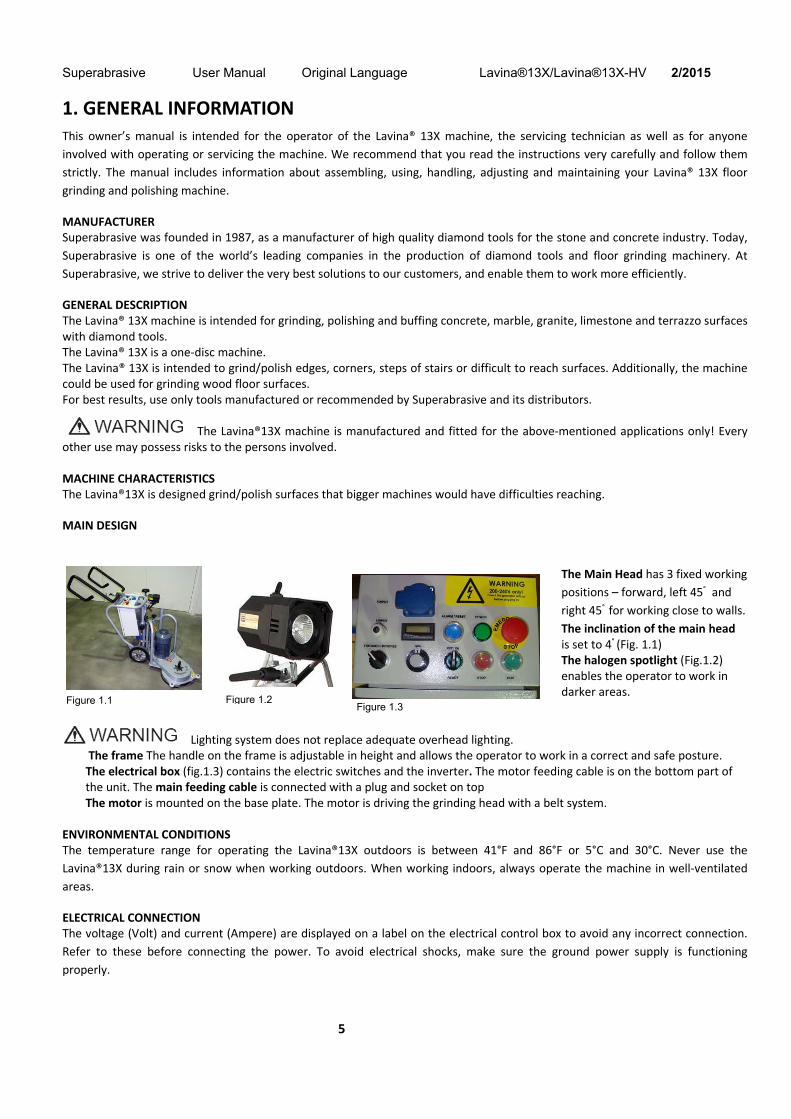
The Main Head has 3 fixed working
positions – forward, left 45° and
right 45° for working close to walls.
The inclination of the main head is set to 4° (Fig. 1.1) The halogen spotlight (Fig.1.2) enables the operator to work in darker areas.
Lighting system does not replace adequate overhead lighting. The frame The handle on the frame is adjustable in height and allows the operator to work in a correct and safe posture. The electrical box (fig.1.3) contains the electric switches and the inverter. The motor feeding cable is on the bottom part of the unit. The main feeding cable is connected with a plug and socket on top The motor is mounted on the base plate. The motor is driving the grinding head with a belt system.
ENVIRONMENTAL CONDITIONS The temperature range for operating the Lavina®13X outdoors is between 41°F and 86°F or 5°C and 30°C. Never use the
Lavina®13X during rain or snow when working outdoors. When working indoors, always operate the machine in well‐ventilated
areas.
ELECTRICAL CONNECTION The voltage (Volt) and current (Ampere) are displayed on a label on the electrical control box to avoid any incorrect connection.
Refer to these before connecting the power. To avoid electrical shocks, make sure the ground power supply is functioning
properly.
Figure 1.2 Figure 1.1 Figure 1.3
Superabrasive User Manual Original Language Lavina®13X/Lavina®13X-HV 2/2015
6
VACUUM CONNECTION A connection for a vacuum dust extractor is located on the handle. The Lavina®13X does not include a vacuum dust extractor. The
customer must purchase the vacuum dust extractor separately. The hose of the vacuum extractor must be Ø 50.8 mm and can be
glided over the pipe. The vacuum dust extractor must be adapted for floor grinders and have a minimum air displacement of
300m3/h with a negative vacuum of 21 kPa.
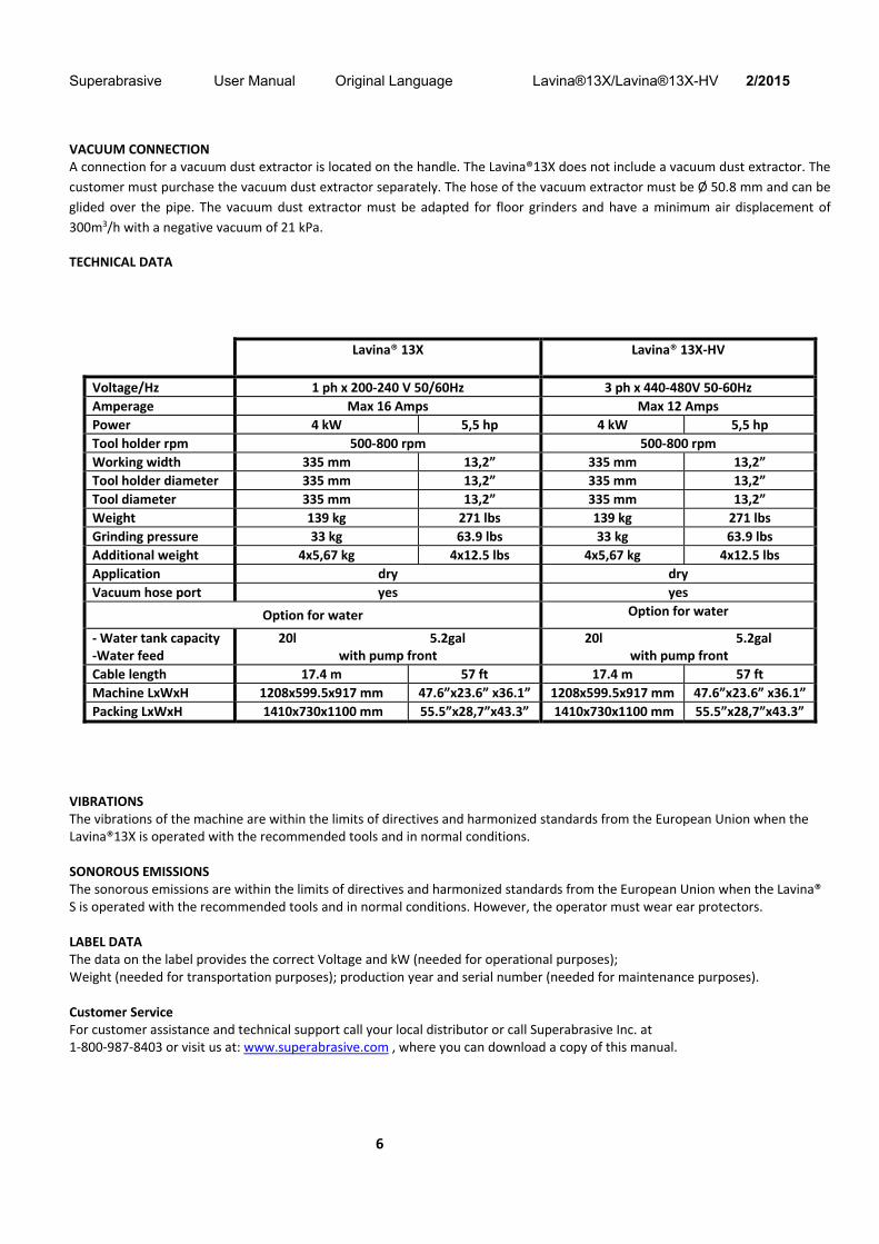
TECHNICAL DATA
VIBRATIONS The vibrations of the machine are within the limits of directives and harmonized standards from the European Union when the Lavina®13X is operated with the recommended tools and in normal conditions.
SONOROUS EMISSIONS The sonorous emissions are within the limits of directives and harmonized standards from the European Union when the Lavina® S is operated with the recommended tools and in normal conditions. However, the operator must wear ear protectors.
LABEL DATA The data on the label provides the correct Voltage and kW (needed for operational purposes); Weight (needed for transportation purposes); production year and serial number (needed for maintenance purposes).
Customer Service For customer assistance and technical support call your local distributor or call Superabrasive Inc. at 1‐800‐987‐8403 or visit us at: www.superabrasive.com , where you can download a copy of this manual.
Lavina® 13X Lavina® 13X‐HV
Voltage/Hz 1 ph x 200‐240 V 50/60Hz 3 ph x 440‐480V 50‐60Hz
Amperage Max 16 Amps Max 12 Amps
Power 4 kW 5,5 hp 4 kW 5,5 hp
Tool holder rpm 500‐800 rpm 500‐800 rpm
Working width 335 mm 13,2” 335 mm 13,2”
Tool holder diameter 335 mm 13,2” 335 mm 13,2”
Tool diameter 335 mm 13,2” 335 mm 13,2”
Weight 139 kg 271 lbs 139 kg 271 lbs
Grinding pressure 33 kg 63.9 lbs 33 kg 63.9 lbs
Additional weight 4x5,67 kg 4x12.5 lbs 4x5,67 kg 4x12.5 lbs
Application dry dry
Vacuum hose port yes yes
Option for water Option for water
‐ Water tank capacity ‐Water feed
20l 5.2gal with pump front
20l 5.2gal with pump front
Cable length 17.4 m 57 ft 17.4 m 57 ft
Machine LxWxH 1208x599.5x917 mm 47.6”x23.6” x36.1” 1208x599.5x917 mm 47.6”x23.6” x36.1”
Packing LxWxH 1410x730x1100 mm 55.5”x28,7”x43.3” 1410x730x1100 mm 55.5”x28,7”x43.3”
Superabrasive User Manual Original Language Lavina®13X/Lavina®13X-HV 2/2015
7
2. SAFETY INSTRUCTION
RECOMMENDED USEThe Lavina®13X machine is designed and manufactured to grind and polish concrete, terrazzo and natural stone floors. It can be used for renovations as well as for polishing. The machine is designed for dry use. Use a vacuum of appropriate size. For more information, please refer to the chapter on handling the vacuum connection.
PROHIBITED USE The machine MUST NOT be used:
For applications different from the ones stated in the General
Description chapter.
For unsuitable materials. In environments which:
Possess risks of explosion
Possess high concentration of powders or oilsubstances
in the air
Possess risks of fire
Feature inclement conditions.
Possess electromagnetic radiation.
PREPARATION FOR WORK Make sure that:
You have closed the work area, so that no person unfamiliar
with operating the machine can enter the area
The tool plate and tools are adjusted to the machine properly There are no missing parts of the machine The machine is in upright working position The protection devices are working properly. The electrical cable is free to move and follow the machine easily. In order to keep the electrical cable from being damaged, no vehicle should cross the zone where electrical cables are situated.
PROTECTION DEVICES The machine is equipped with several protection devices including the following: An emergency stop button A protection skirt and a hood for protecting the tool plates. These devices protect the operator and/or others persons from potential injuries. Do not remove them. On counterry, before using the machine, please ensure that all protection devices are mounted and function properly.
ARREST FUNCTIONSFunctions of arresting of the machine are following:
Button to stop the motor (category 1) Emergency button (category 1)
SAFE USEThe Lavina®13X is designed to eliminate all risks correlated with its use. However, it is not possible to eliminate the risks of an eventual accident with the machine. Unskilled or
uninstructed operator may cause correlated residual risks. Such risks are: Position Risks due to operator’s incorrect working position Entanglement Risks due to wearing inappropriate working clothes Training Risks due to lack of operational training NOTE: In order to reduce all consequences of the above‐
mentioned risks, we advise that machine operators will follow
the instructions in the manual at all times.
RESIDUAL RISKS During the normal operating and maintenance cycles, the operator is exposed to few residual risks, which cannot be eliminated due to the nature of the operations.
BEFORE YOU BEGINWorking area must be clear from any debris or objects. A first‐time operator must always read the manual and pay attention to all safety instructions. All electric connections and cables must be inspected for potential damages. Ground wire system of the power supply must be also inspected. Perform general daily inspections of the machine and inspect the machine before each use. Always inspect the safety devices: The emergency break must be clear and working The tool protector must be working The machine must be clean Never operate the machine in the rain! Confirm that there are no missing parts especially after transportation, repair or maintenance.
OPERATING MACHINE When operating the Lavina®13X, make certain that there is no one, but you around the machine. Never leave the machine unattended while working. The electrical cable must move freely and must be damage‐free. Check if the floor, you work on, is not too uneven. If this is the case, it may damage the machine.
AFTER WORK IS COMPLETED Clean the machine and its surroundings properly Unplug the machine and wind up the electrical cable Store the machine in a safe place
THE WORK AREA Prevent persons and vehicles from entering the work area. Clear the path of hoses and cables Always check the floor for debris
PERSONAL PROTECTIVE EQUIPMENT (PPE) Always wear safety shoes when working with the machine. Always wear ear protectors when working with the machine.
Superabrasive User Manual Original Language Lavina®13X/Lavina®13X-HV 2/2015
8
All personnel in the immediate work area must wear safety glasses with side shields. Always wear safety gloves when changing the tools. Always wear clothes suitable for the work environment.
OPERATORThe Lavina®13X machine. The operator must know the machine’s work environment. Only one operator can work with the machine at a time. The operator must be properly trained and well instructed prior operating the machine.
The operator must understand all the instructions in this manual. The operator must understand and be able to interpret all the drawings and designs in manual. The operator must know all sanitation and safety regulations pertaining to the operation of The operator must have floor grinding experience. The operator must know what to do in case of emergency. The operator must have an adequate technical knowledge and preparation.
3. OPERATIONPRELIMINARY CONTROLS Inspect the working area as explained in the safety instructions. For dry use, connect the vacuum extractor and ensure that the
vacuum hose is clear and it will follow the machine easily. Plug in the machine and make sure that the power cord is free to follow the
working direction of the Lavina®13X.
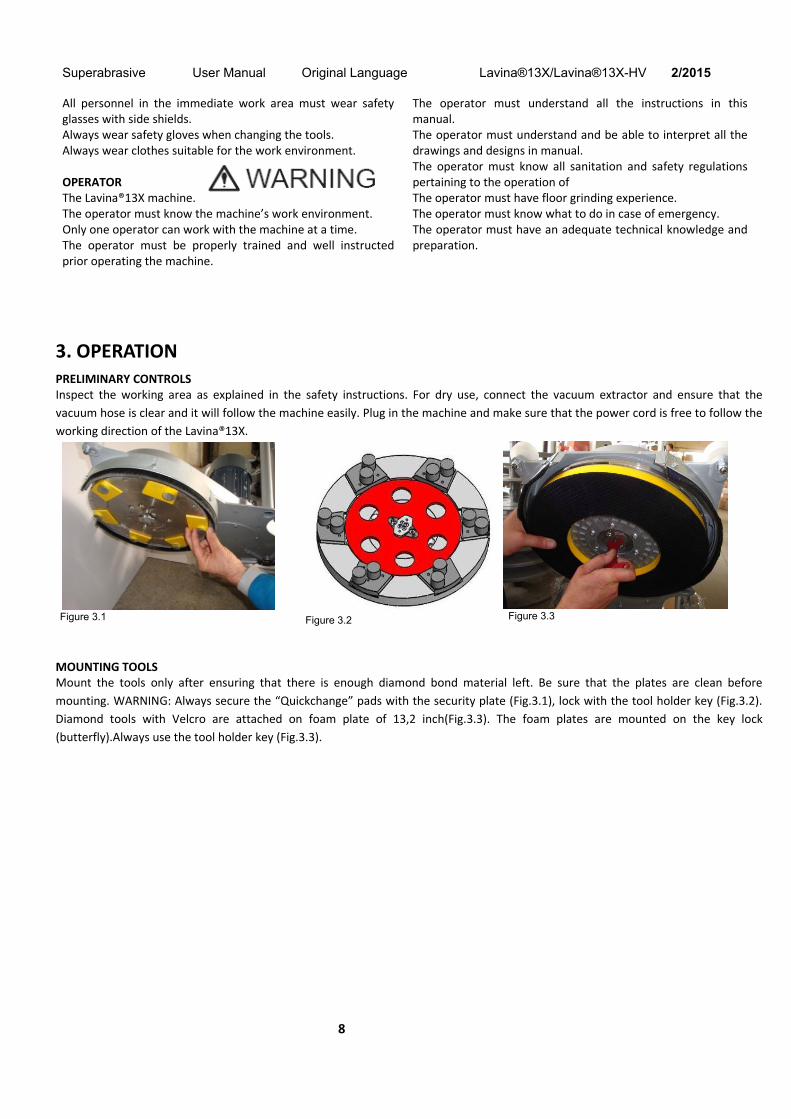
MOUNTING TOOLS Mount the tools only after ensuring that there is enough diamond bond material left. Be sure that the plates are clean before
mounting. WARNING: Always secure the “Quickchange” pads with the security plate (Fig.3.1), lock with the tool holder key (Fig.3.2).
Diamond tools with Velcro are attached on foam plate of 13,2 inch(Fig.3.3). The foam plates are mounted on the key lock
(butterfly).Always use the tool holder key (Fig.3.3).
Figure 3.1 Figure 3.2 Figure 3.3
Superabrasive User Manual Original Language Lavina®13X/Lavina®13X-HV 2/2015
9
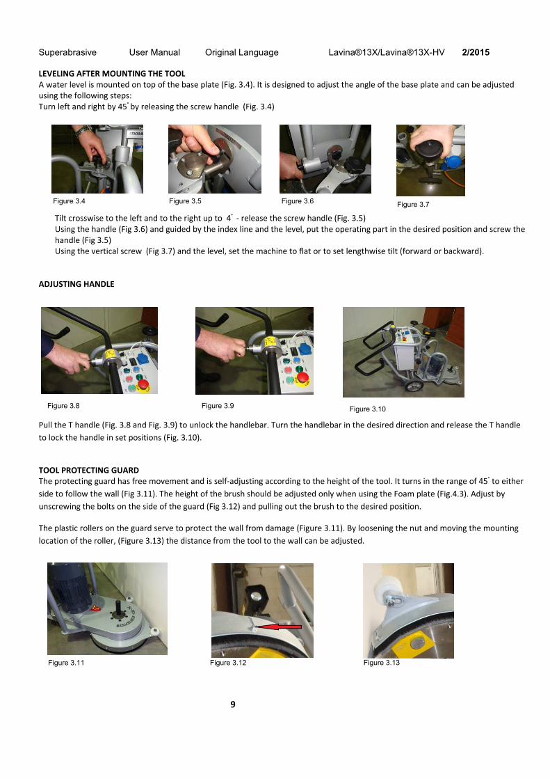
LEVELING AFTER MOUNTING THE TOOL A water level is mounted on top of the base plate (Fig. 3.4). It is designed to adjust the angle of the base plate and can be adjusted using the following steps: Turn left and right by 45° by releasing the screw handle (Fig. 3.4)
Tilt crosswise to the left and to the right up to 4° ‐ release the screw handle (Fig. 3.5) Using the handle (Fig 3.6) and guided by the index line and the level, put the operating part in the desired position and screw the handle (Fig 3.5) Using the vertical screw (Fig 3.7) and the level, set the machine to flat or to set lengthwise tilt (forward or backward).
ADJUSTING HANDLE
Pull the T handle (Fig. 3.8 and Fig. 3.9) to unlock the handlebar. Turn the handlebar in the desired direction and release the T handle
to lock the handle in set positions (Fig. 3.10).
TOOL PROTECTING GUARD The protecting guard has free movement and is self‐adjusting according to the height of the tool. It turns in the range of 45° to either
side to follow the wall (Fig 3.11). The height of the brush should be adjusted only when using the Foam plate (Fig.4.3). Adjust by
unscrewing the bolts on the side of the guard (Fig 3.12) and pulling out the brush to the desired position.
The plastic rollers on the guard serve to protect the wall from damage (Figure 3.11). By loosening the nut and moving the mounting
location of the roller, (Figure 3.13) the distance from the tool to the wall can be adjusted.
Figure 3.13 Figure 3.12
Figure 3.8 Figure 3.9 Figure 3.10
Figure 3.11
Figure 3.4 Figure 3.5 Figure 3.6 Figure 3.7

Superabrasive User Manual Original Language Lavina®13X/Lavina®13X-HV 2/2015
10
THE CONTROL BOARD 1. Digital Tachometer Indicates the revolution per minute of
the grinding plates.2. Alarm/Reset button resets the alarm of the inverter.
Button lights blue when the inverter goes into alarmmode.
3. Power led lights green when the power is on
4. Emergency button stops the motor in case ofemergency
5. Forward/Reverse switch Select forward for clockwiserotation of the grinding plates or reverse forcounterclockwise rotation of the grinding plates(Recommended configuration). The preferred operatingdirection should be when the switch is in the forwardposition. The proper direction of rotation of the motor(counterclockwise) is indicated by an arrow on its cover
6. Potentiometer controls the RPM of the grinding plates ona range of 500‐800 rpm
7. Ready OFF/ON switch Switching to ON puts the machine in standby mode. The switch lights to indicate this.Switching to OFF takes the machine out of standby. The light extinguishes to indicate this.The switch returns to its starting position after being released.
8. OFF button stops motor 9. RUN button starts motor
STARTING THE MACHINE First, follow the directions in the chapter on Safety Devices and Safety Instructions. Next, release the emergency stop (Fig. 3.14‐4) and
turn the Ready switch (Fig. 3.14‐7) to ON to put the machine in standby mode. Check the potentiometer (Fig. 3.14‐6) and ensure that
it is set to the working speed. Switch on the vacuum unit. Finally, hold the machine firmly and push the run button (Fig. 3.14‐9).
OPERATING THE MACHINE Work at a constant speed allowing the tools time to work at a speed appropriate for the tools’ grit size. Avoid vibrations. Do not stop
the Lavina ®13X machine in one spot while the tools are still working because they will leave marks on the floor surface. Check the
floor surface periodically to ensure that dust is not accumulating on the surface, also check regularly if your vacuum works properly.
In case you use Lavina ®13X as one disc machine for floor maintenance guide the machine in straight lines across the floor, and with
each new line overlap a little bit of the previously completed surface.
STOPPING THE MACHINE The stopping of the machine must be done gradually until the motor stops. Do not stop moving the machine before the motor comes to rest, as the tools could damage the surface. To stop the machine: 1.Push the STOP button (8) .2.Turn the ON/OFF (7) switch in position OFF, this will cut the voltage to the invertor and the green light will turn off.
While working, do not turn off directly from the Ready switch or from the Emergency Stop, bmentioned steps 1 and .
Use the Emergency button (4) only in case of emergency. Remember not to hold the machine in one spot before turning off the motor.
Figure 3.14
Superabrasive User Manual Original Language Lavina®13X/Lavina®13X-HV 2/2015
11
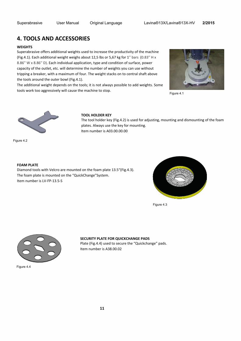
4. TOOLS AND ACCESSORIESWEIGHTS Superabrasive offers additional weights used to increase the productivity of the machine
(Fig.4.1). Each additional weight weighs about 12,5 lbs or 5,67 kg for 1'' bars (0.83'' H x
8.86'' W x 8.86'' D). Each individual application, type and condition of surface, power
capacity of the outlet, etc. will determine the number of weights you can use without
tripping a breaker, with a maximum of four. The weight stacks on to central shaft above
the tools around the outer bowl (Fig.4.1).
The additional weight depends on the tools; it is not always possible to add weights. Some
tools work too aggressively will cause the machine to stop.
TOOL HOLDER KEY The tool holder key (Fig.4.2) is used for adjusting, mounting and dismounting of the foam
plates. Always use the key for mounting.
Item number is A03.00.00.00
FOAM PLATE Diamond tools with Velcro are mounted on the foam plate 13.5“(Fig.4.3).
The foam plate is mounted on the “QuickChange”System.
Item number is LV‐FP‐13.5‐S
SECURITY PLATE FOR QUICKCHANGE PADS Plate (Fig.4.4) used to secure the “Quickchange” pads.
Item number is A38.00.02
Figure 4.2
Figure 4.3
Figure 4.4
Figure 4.1
Superabrasive User Manual Original Language Lavina®13X/Lavina®13X-HV 2/2015
12
5. POPULAR TOOLSRECOMMENDED TOOLS
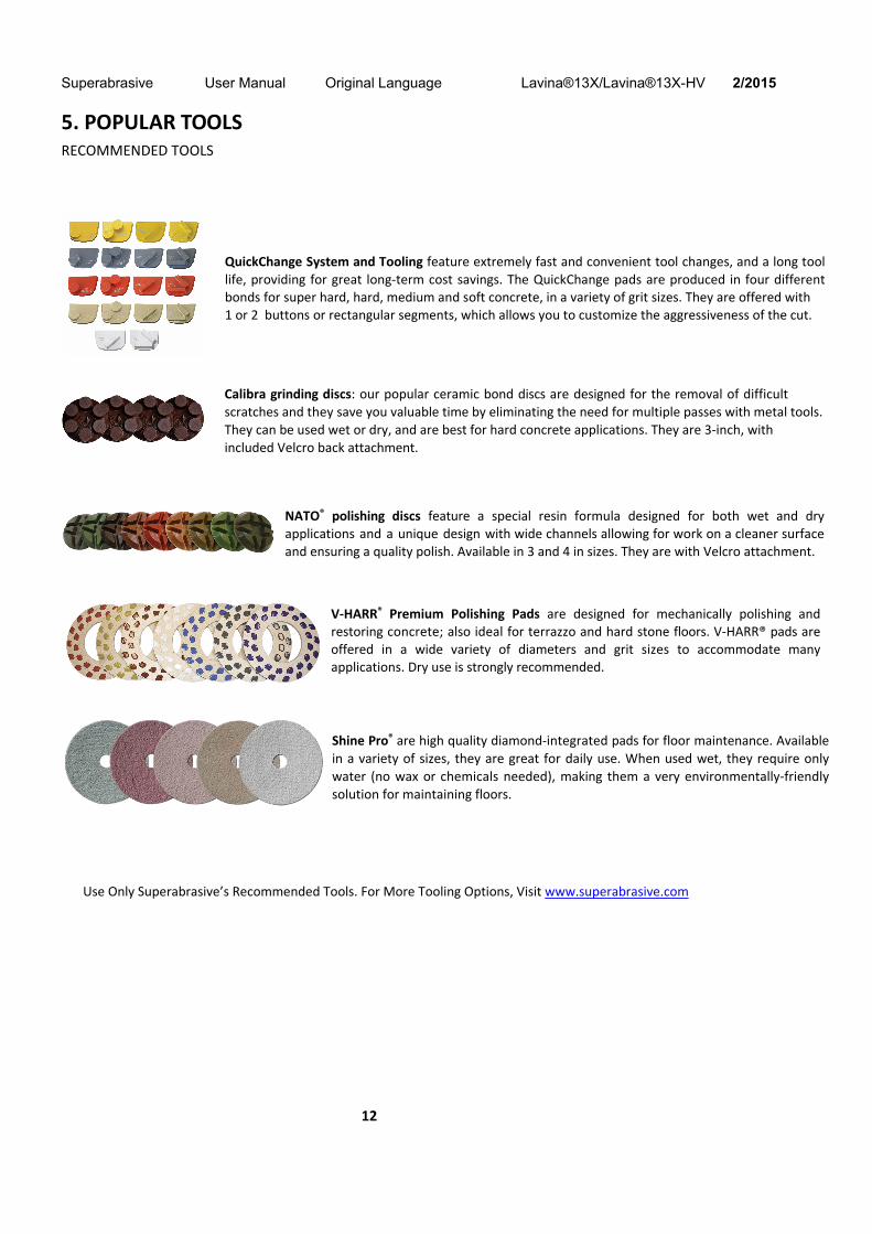
QuickChange System and Tooling feature extremely fast and convenient tool changes, and a long tool life, providing for great long‐term cost savings. The QuickChange pads are produced in four different bonds for super hard, hard, medium and soft concrete, in a variety of grit sizes. They are offered with 1 or 2 buttons or rectangular segments, which allows you to customize the aggressiveness of the cut.
Calibra grinding discs: our popular ceramic bond discs are designed for the removal of difficult scratches and they save you valuable time by eliminating the need for multiple passes with metal tools. They can be used wet or dry, and are best for hard concrete applications. They are 3‐inch, with included Velcro back attachment.
NATO® polishing discs feature a special resin formula designed for both wet and dry applications and a unique design with wide channels allowing for work on a cleaner surface and ensuring a quality polish. Available in 3 and 4 in sizes. They are with Velcro attachment.
V‐HARR® Premium Polishing Pads are designed for mechanically polishing and restoring concrete; also ideal for terrazzo and hard stone floors. V‐HARR® pads are offered in a wide variety of diameters and grit sizes to accommodate many applications. Dry use is strongly recommended.
Shine Pro® are high quality diamond‐integrated pads for floor maintenance. Available
in a variety of sizes, they are great for daily use. When used wet, they require only
water (no wax or chemicals needed), making them a very environmentally‐friendly
solution for maintaining floors.
Use Only Superabrasive’s Recommended Tools. For More Tooling Options, Visit www.superabrasive.com

Superabrasive User Manual Original Language Lavina®13X/Lavina®13X-HV 2/2015
13
6. MAINTENANCE AND INSPECTION CLEANING Keep your machine clean. Cleaning the machine on a regular basis will help detect and solve
potential problems before they cause damage to the machine. Most importantly, check and clean
the tool plate connections, power cord and plugs, vacuum hoses.
CHECK DAILY After operating the Lavina®13X machine, the operator should conduct a visual inspection of the
machine. Any defect should be solved immediately. Pay attention to power cords, plugs and vacuum
hoses, loose bolt or screws.
Tool holders: Buffers and elastic element are consumables and must be visually checked daily and
replaced if needed. See flanges or discs are mounted locked well in place .
The key lock holders should be also checked.
Check the rubber buffers and fixing of the holders. The flange holding the buffers (Fig.6.1‐1 ) and
elastic element must be firmly fixed to the unit. A gap seen here indicates loose screws fixing the
holder. The screws must be tightened immediately for safe operation. Working with loose screws on the holder could also cause bad
damages to the machine.
It is very important to regularly check the screws(Fig.6.1‐2) that fix the "Quickchange" holder to the safety part, so that
holder will not fly away if the buffers get damaged.“Quickchange” should also be cleaned.
CHECK AFTER THE FIRST 15 WORKING HOURS Check the belt tension after 15 hours working with the machine.
For instructions to correct tension, see TROUBLESHOOTING.
CHECK EVERY 200 WORKING HOURS Every 200 working hours, the operator should inspect all parts of the machine carefully. Most importantly, inspect and clean the tool
plate connections, power cord and plugs, vacuum. Check the guard assembly. Make certain the wheels are clean and rotate properly.
Inspect the control buttons. If there are defective control parts, they should be replaced immediately. Replace worn vacuum‐ and
water hoses. Carefully inspect the seal rings and bearings of the grinding units, and replace any showing signs of excessive wear.
For more information, refer to chapter troubleshooting below.
CHECK EVERY 500 WORKING HOURS In addition to the checks made every 200 working hours, open up the bottom cover like described in chapter “TROUBLE SHOOTING
REPLACING BELT Check if sealers, belt and bearings are in good condition, change if needed. Be wary when tensioning the belt not to
“over tension”; the belt will not regain its original tension.
VACUUM As stated previously, frequently check hoses and other parts for clogging.
MECHANICAL PARTS Parts such as the belt, seal rings, cap rings, spiders and buffers and guard assembly are subject to wear and should be replaced as
needed.
ELECTRICAL SYSTEM Dust should not enter the control box as it will destroy the contacts.
Remove (blow out) any dust present.
Figure 6.1

Superabrasive User Manual Original Language Lavina®13X/Lavina®13X-HV 2/2015
14
LAVINA® 13X ELECTRICAL SCHEMES WITH YASKAWA INVERTER 200‐240 VOLT
LAVINA® 13X ELECTRICAL SCHEMES YASKAWA CONNECTION MAIN CIRCUIT TERMINALS
The motor is connected in “Delta”
(triangle) 230 Volt,
reminder for the wire connection
of the motor
Figure 6.4
Figure 6.3
Superabrasive User Manual Original Language Lavina®13X/Lavina®13X-HV 2/2015
15
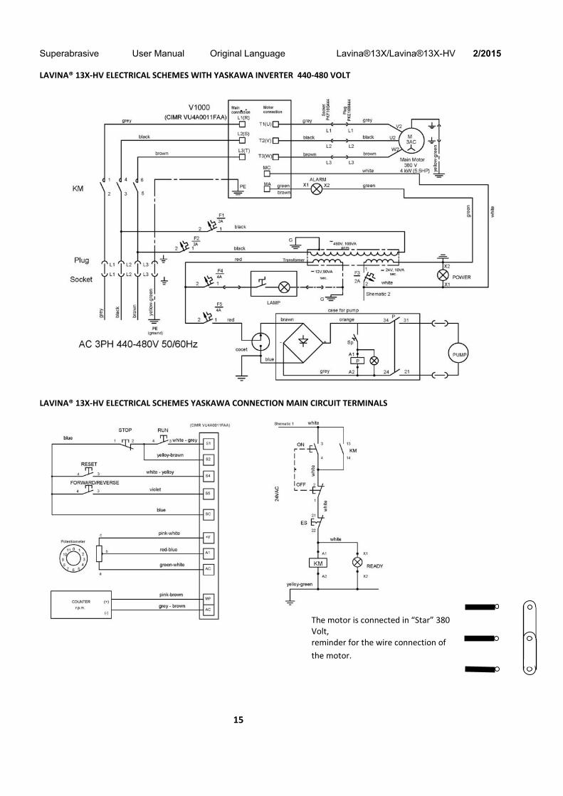
LAVINA® 13X‐HV ELECTRICAL SCHEMES WITH YASKAWA INVERTER 440‐480 VOLT
LAVINA® 13X‐HV ELECTRICAL SCHEMES YASKAWA CONNECTION MAIN CIRCUIT TERMINALS
The motor is connected in “Star” 380 Volt, reminder for the wire connection of
the motor.
Superabrasive User Manual Original Language Lavina®13X/Lavina®13X-HV 2/2015
16
7. TROUBLESHOOTING
INDEX OF PROBLEMS AND SOLUTIONS
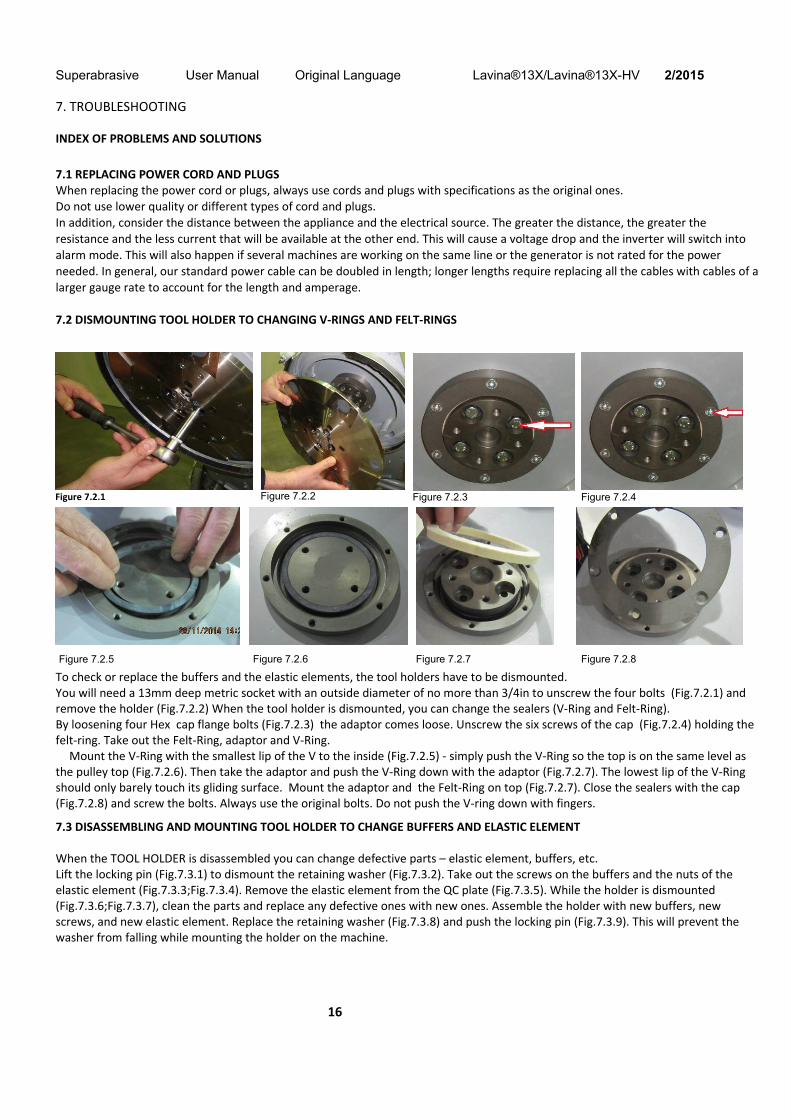
7.1 REPLACING POWER CORD AND PLUGS When replacing the power cord or plugs, always use cords and plugs with specifications as the original ones. Do not use lower quality or different types of cord and plugs. In addition, consider the distance between the appliance and the electrical source. The greater the distance, the greater the resistance and the less current that will be available at the other end. This will cause a voltage drop and the inverter will switch into alarm mode. This will also happen if several machines are working on the same line or the generator is not rated for the power needed. In general, our standard power cable can be doubled in length; longer lengths require replacing all the cables with cables of a larger gauge rate to account for the length and amperage. 7.2 DISMOUNTING TOOL HOLDER TO CHANGING V‐RINGS AND FELT‐RINGS
To check or replace the buffers and the elastic elements, the tool holders have to be dismounted. You will need a 13mm deep metric socket with an outside diameter of no more than 3/4in to unscrew the four bolts (Fig.7.2.1) and remove the holder (Fig.7.2.2) When the tool holder is dismounted, you can change the sealers (V‐Ring and Felt‐Ring). By loosening four Hex cap flange bolts (Fig.7.2.3) the adaptor comes loose. Unscrew the six screws of the cap (Fig.7.2.4) holding the felt‐ring. Take out the Felt‐Ring, adaptor and V‐Ring.
Mount the V‐Ring with the smallest lip of the V to the inside (Fig.7.2.5) ‐ simply push the V‐Ring so the top is on the same level as the pulley top (Fig.7.2.6). Then take the adaptor and push the V‐Ring down with the adaptor (Fig.7.2.7). The lowest lip of the V‐Ring should only barely touch its gliding surface. Mount the adaptor and the Felt‐Ring on top (Fig.7.2.7). Close the sealers with the cap (Fig.7.2.8) and screw the bolts. Always use the original bolts. Do not push the V‐ring down with fingers.
7.3 DISASSEMBLING AND MOUNTING TOOL HOLDER TO CHANGE BUFFERS AND ELASTIC ELEMENT When the TOOL HOLDER is disassembled you can change defective parts – elastic element, buffers, etc. Lift the locking pin (Fig.7.3.1) to dismount the retaining washer (Fig.7.3.2). Take out the screws on the buffers and the nuts of the elastic element (Fig.7.3.3;Fig.7.3.4). Remove the elastic element from the QC plate (Fig.7.3.5). While the holder is dismounted (Fig.7.3.6;Fig.7.3.7), clean the parts and replace any defective ones with new ones. Assemble the holder with new buffers, new screws, and new elastic element. Replace the retaining washer (Fig.7.3.8) and push the locking pin (Fig.7.3.9). This will prevent the washer from falling while mounting the holder on the machine.
Figure 7.2.1 Figure 7.2.2 Figure 7.2.3 Figure 7.2.4
Figure 7.2.5 Figure 7.2.6 Figure 7.2.7 Figure 7.2.8

Superabrasive User Manual Original Language Lavina®13X/Lavina®13X-HV 2/2015
17
Make sure sure the four bolts holding the adaptor (Fig.7.3.12) are reliably tightened. Mount the holder on the machine using the same socket as in 7.2 (Fig.7.3.10;Fig.7.3.11). The retaining washer fits into the central hole C of adaptor and the four bolts into the thread holes Т (Fig.7.3.12). The holder is centered on the outside diameter of the adaptor. Ensure the holder is properly connected to the plate of the adaptor and then tight evenly the four bolts. Tightening force on the bolts has to be 22...25N.m(16...18 lbf.ft). Mounting the holder without the retaining washer (Fig.7.3.2) is INADMISSIBLE because the security system preventing the separation of part of the holder in case of broken buffers and elastic element will not function! You can change the butterfly of the holder without dismounting the holder from the machine. Fig.7.3.13 is a 3‐d section view of the holder, showing its parts. The numbering is the same as in Spare parts.
Figure 7.3.10 Figure 7.3.11
T C
Figure 7.3.12
Figure 7.3.5
Figure 7.3.1 Figure 7.3.2
Figure 7.3.7
Figure 7.3.4
Figure 7.3.8 Figure 7.3.9
Figure 7.3.6
Figure 7.3.3
Figure 7.3.13
Superabrasive User Manual Original Language Lavina®13X/Lavina®13X-HV 2/2015
18
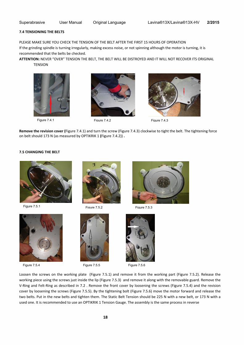
7.4 TENSIONING THE BELTS
PLEASE MAKE SURE YOU CHECK THE TENSION OF THE BELT AFTER THE FIRST 15 HOURS OF OPERATION
If the grinding spindle is turning irregularly, making excess noise, or not spinning although the motor is turning, it is
recommended that the belts be checked.
ATTENTION: NEVER “OVER” TENSION THE BELT, THE BELT WILL BE DISTROYED AND IT WILL NOT RECOVER ITS ORIGINAL
TENSION
Remove the revision cover (Figure 7.4.1) and turn the screw (Figure 7.4.3) clockwise to tight the belt. The tightening force on belt should 173 N (as measured by OPTIKRIK 1 (Figure 7.4.2)) .
7.5 CHANGING THE BELT
Loosen the screws on the working plate (Figure 7.5.1) and remove it from the working part (Figure 7.5.2). Release the
working piece using the screws just inside the lip (Figure 7.5.3) and remove it along with the removable guard. Remove the
V‐Ring and Felt‐Ring as described in 7.2 . Remove the front cover by loosening the screws (Figure 7.5.4) and the revision
cover by loosening the screws (Figure 7.5.5). By the tightening bolt (Figure 7.5.6) move the motor forward and release the
two belts. Put in the new belts and tighten them. The Static Belt Tension should be 225 N with a new belt, or 173 N with a
used one. It is recommended to use an OPTIKRIK 1 Tension Gauge. The assembly is the same process in reverse
Figure 7.4.3Figure 7.4.2Figure 7.4.1
Figure 7.5.3Figure 7.5.2Figure 7.5.1
Figure 7.5.4 Figure 7.5.5 Figure 7.5.6
Superabrasive User Manual Original Language Lavina®13X/Lavina®13X-HV 2/2015
19
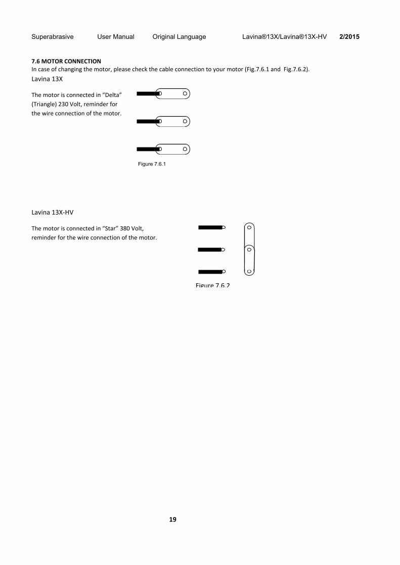
7.6 MOTOR CONNECTION In case of changing the motor, please check the cable connection to your motor (Fig.7.6.1 and Fig.7.6.2).
Lavina 13X
The motor is connected in “Delta”
(Triangle) 230 Volt, reminder for
the wire connection of the motor.
Lavina 13X‐HV
The motor is connected in “Star” 380 Volt,
reminder for the wire connection of the motor.
Figure 7.6.1
Figure 7.6.2

Superabrasive User Manual Original Language Lavina®13X/Lavina®13X-HV 2/2015
20
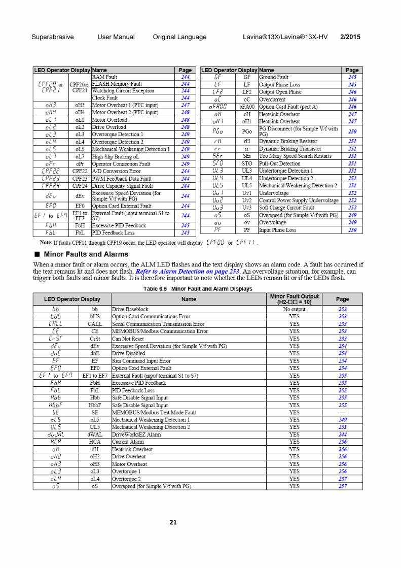
7.7 FAULT DIAGNOSIS INVERTER YASKAWA V1000 Pages are referring to
Yaskawa Electric SIEP C710606 18A YASKAWA AC Drive – V1000 Technical Manual
Superabrasive User Manual Original Language Lavina®13X/Lavina®13X-HV 2/2015
21
Superabrasive User Manual Original Language Lavina®13X/Lavina®13X-HV 2/2015
22
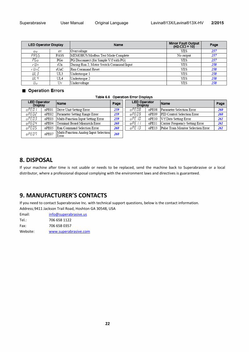
8. DISPOSAL If your machine after time is not usable or needs to be replaced, send the machine back to Superabrasive or a local
distributor, where a professional disposal complying with the environment laws and directives is guaranteed.
9. MANUFACTURER’S CONTACTS If you need to contact Superabrasive Inc. with technical support questions, below is the contact information.
Address; 9411 Jackson Trail Road, Hoshton GA 30548, USA
Email: [email protected]
Tel.: 706 658 1122
Fax: 706 658 0357
Website: www.superabrasive.com

Superabrasive User Manual Original Language Lavina®13X/Lavina®13X-HV 2/2015
23
10. SPARE PARTS ASSEMBLY AND PARTS SPECIFICATIONS
1. LAVINA®13X GENERAL PARTS
No. Item No. Description Pcs.
1 L13X.10.00.00 Main Head 1
2 L13X.20.00.00 Carriage 1
3 L13X.30.00.00 Electric Cabinet 1
4 M16DIN125A Washer 2
5 M16DIN982 Self Locking Nut 2
6 М8х20DIN6921 Bolt 4
2. LAVINA®13X MAIN HEAD 1
No. Item No. Description Pcs.
1 М8х25DIN933 Bolt 4
2 М8DIN127B Spring Washer 4
3 М8DIN125A Washer 4
4 M10DIN125A Washer 4
5 М10DIN127B Spring Washer 5
6 M10x25DIN933 Bolt 4
7 М4х12DIN85A Screw М4х12 2
8 DWL‐K5 Double Water Level 1
9 L13S‐10.70.00 Weights Holder 1
10 M5x12DIN6921 Bolt 2
11 М8х12DIN7991‐10.9 Screw 6
12 L13S‐10.20.00 ‐SET Frame SET 1
13 XPZ 887 Belt 2
14 L13X.10.10.00 Driven Bearing 1
15 M6x12DIN7991 Screw 9
16 L13S‐10.00.40 Disc Cover 1
17 M6x20DIN7991 Screw 5
18 L25LS‐14.00.02 Flange 1
19 М5х10DIN933 Bolt 6
20 М5DIN7980 Spring Washer 6
21 L13S‐10.00.20 Cover 1
22 М6х20DIN912 Screw 4
23 M10x70DIN931 Bolt 1
24 M6DIN125A Washer М6 4
25 M6DIN985 Self Locking Nut 4
26 L13S‐10.50.00 Tubular Axle 1
27 L7P‐00.00.00.02 Handle М12 1
28 M6x14DIN912 Screw 3
29 L13S‐10.30.00 Plate Strain 1
30 L25SPS‐00.00.00.15 Front Washer 1
31 L13S‐10.00.08 Belt Sheave 1
32 S‐131 Electro Motor 1
32.1 L13N‐S‐10.00.53‐01 Fan Cover 1
32.2 L13N‐S‐10.00.53‐02 Fan 1

Superabrasive User Manual Original Language Lavina®13X/Lavina®13X-HV 2/2015
24
3. LAVINA®13X MAIN HEAD 2
No. Item No. Description Pcs.
1 L13‐S‐10.00.22 Axis Roll 2
2 РО 050 19 22 OG Roll РО 2
3 М8DIN134 Washer 2
4 М8DIN125A Washer 2
5 M8DIN 982 Self Locking Nut 2
6 М5DIN7980 Spring Washer 6
7 M5x12DIN912 Screw 6
8 TWVA00800 V‐Ring Type A 1
9 A42.03.00 Adaptor 1
10 110X90X8.5 Felt Ring 1
11 L13‐S‐10.00.11 Protecting Disc 1
12 М5DIN125А Washer 7
13 М5х8DIN933 Bolt 7
14 L13‐S‐10.00.38 Strip Brush 1
15 L13‐S‐10.40.00 Succer Cover 1
16 L25LS‐14.00.03 Outer Cover 1
17 M6x12DIN7991 Screw 6
18 A43.00.00 Tool Holder A43 1
18.1 М8х16DIN6921 Bolt 4
4. LAVINA®30G‐X TOOL HOLDER PARTS
No. Item No. Description Pcs.
1 A43.10.00 Quick Change Assembly 1
1.1 A31.12.00 Keylock Set 1
1.2 A43.11.00 Quick Change plate 1
1.3 A41.12.00 Security set 1
1.3.1 A41.00.05 Washer A41 1
2 A25.00.10-K Buffer with two screw 6
2.1 M8X12DIN7991 Screw 12
2.2 A25.00.10 Buffer 6
3 A41.20.03-K Driving Set A41 1
3.1 A41.20.03 Elastic Element 1
3.2 M6DIN985 Self Locking Nut 12
3.3 M6X40DIN7991 Screw 6
3.4 M6X30DIN7991 Screw 6
3.5 A41.21.00 Set of plates 1
4 М8х16DIN6921 Bolt 4
5 A41.20.01 Flange 1
5. LAVINA®13X OPTION FOR WATER
No. Item No. Description Pcs.
1 L13S-40.00.00 Set Water 1

Superabrasive User Manual Original Language Lavina®13X/Lavina®13X-HV 2/2015
25
6. LAVINA®13X CARRIAGE PARTS
No. Item No. Description Pcs. No. Item No. Description Pcs.
1 L25S‐23.10.00 Handle Assembly 1 21 L13S‐21.10.00 Carnage Frame 1
2 L27160 Handle 1 22 L25G ‐20.00.04 Wheel 2
3 L25S‐23.00.09 Nut 1 23 M10X16DIN7991 Screw 2
4 L25S‐23.00.07 Spring 1 24 L32D‐20.00.03 Cap 2
5 L25S‐23.00.06 Axle 1 25 L13S‐20.00.05 Bottom Axle 1
6 M6X12DIN912 Screw 4 26 F17840 Knob Bolt 1
7 L25S.23.00.02 Outer cap 2 27 M10DIN125A Washer 1
8 M8X12DIN7991 Screw 4 28 L13X‐20.20.00 Axle 1
9 L13S‐20.00.18 Plate 1 29 M10DIN440R Washer 1
10 M16 DIN982 Self Locking Nut 2 30 M6X20DIN7991 Screw 4
11 L13X‐20.00.23 Washer 1 31 L13S‐20.40.00 Screw Flat 1
12 L13X‐20.10.00 Frame 1 32 M6 DIN125B Washer 4
13 L13S‐20.00.21 Axle 2 33 L20NS‐30.30.00 Lamp Unit Incl. Cable 1
14 L13S‐20.00.23 Washer 2 34 M6DIN127B Spring Washer 4
15 M16DIN125A Washer 1 35 M6X16DIN912 Screw 4
16 M12 DIN125A Washer 2 36 L13S‐20.00.32 Handle 1
17 M12 DIN982 Self Locking Nut 2 37 M8X16DIN912 Screw 1
18 L13S‐21.00.06 Bush 1 38 M8DIN433 Washer 1
19 L13S‐21.20.00 Connecting Rod 1 39 M6X8DIN915 Screw 1
20 L13S‐21.00.07 Washer 1
Superabrasive User Manual Original Language Lavina®13X/Lavina®13X-HV 2/2015
26
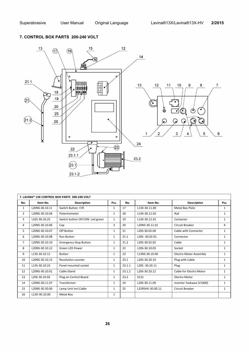
7. CONTROL BOX PARTS 200-240 VOLT
7. LAVINA® 13X CONTROL BOX PARTS 200‐240 VOLT
No. Item No. Description Pcs. No. Item No. Description Pcs.
1 L20NS‐30.10.11 Switch Button F/R 1 17 L13X‐30.11.00 Metal Box Plate 1
2 L20NS‐30.10.04 Potentiometer 1 18 L13X‐30.11.02 Rail 1
3 L32S‐30.10.25 Switch button OFF/ON Led green 1 19 L13X‐30.11.01 Contactor 1
4 L20NS‐30.10.06 Cap 3 20 L20NS‐30.11.01 Circuit Breaker 4
5 L20NS‐30.10.07 Off Button 1 21 L20S‐30.02.00 Cable with Connector 1
6 L20NS‐30.10.08 Run Button 1 21.1 L20S ‐30.02.01 Connector 1
7 L20NS‐30.10.10 Emergency Stop Button 1 21.2 L20S‐30.02.02 Cable 1
8 L20NS‐30.10.12 Green LED Power 1 22 L20S‐30.10.03 Socket 1
9 L13S‐30.10.12 Button 1 23 L13NS‐30.10.00 Electro Motor Assembly 1
10 L20NS‐30.10.15 Revolution counter 1 23.1 L20S‐30.20.10 Plug with Cable 1
11 L13S‐30.10.23 Panel mounted socket 1 23.1.1 L20S ‐30.20.11 Plug 1
12 L20NS‐30.10.01 Cable Gland 1 23.1.2 L20S‐30.20.12 Cable for Electro Motor 1
13 L20S‐30.10.02 Plug on Control Board 1 23.2 S131 Electro Motor 1
14 L20NS‐30.11.07 Transformer 1 24 L20S‐30.11.09 Inverter Yaskawa (V1000) 1
15 L20NS‐30.30.00 Lamp Unit Incl.Cable 1 25 L32RSHV‐30.00.11 Circuit Breaker 1
16 L13X‐30.10.00 Metal Box 1
Superabrasive User Manual Original Language Lavina®13X/Lavina®13X-HV 2/2015
27
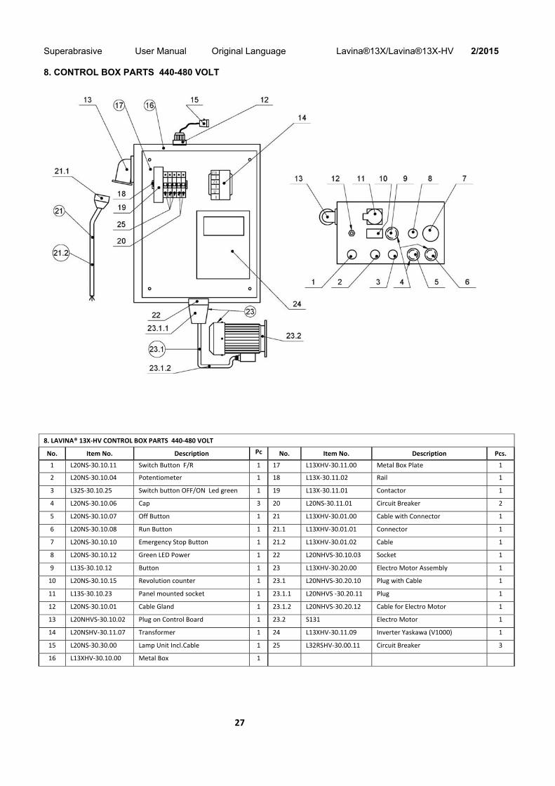
8. CONTROL BOX PARTS 440-480 VOLT
8. LAVINA® 13X‐HV CONTROL BOX PARTS 440‐480 VOLT
No. Item No. Description Pcs
No. Item No. Description Pcs.
1 L20NS‐30.10.11 Switch Button F/R 1 17 L13XHV‐30.11.00 Metal Box Plate 1
2 L20NS‐30.10.04 Potentiometer 1 18 L13X‐30.11.02 Rail 1
3 L32S‐30.10.25 Switch button OFF/ON Led green 1 19 L13X‐30.11.01 Contactor 1
4 L20NS‐30.10.06 Cap 3 20 L20NS‐30.11.01 Circuit Breaker 2
5 L20NS‐30.10.07 Off Button 1 21 L13XHV‐30.01.00 Cable with Connector 1
6 L20NS‐30.10.08 Run Button 1 21.1 L13XHV‐30.01.01 Connector 1
7 L20NS‐30.10.10 Emergency Stop Button 1 21.2 L13XHV‐30.01.02 Cable 1
8 L20NS‐30.10.12 Green LED Power 1 22 L20NHVS‐30.10.03 Socket 1
9 L13S‐30.10.12 Button 1 23 L13XHV‐30.20.00 Electro Motor Assembly 1
10 L20NS‐30.10.15 Revolution counter 1 23.1 L20NHVS‐30.20.10 Plug with Cable 1
11 L13S‐30.10.23 Panel mounted socket 1 23.1.1 L20NHVS ‐30.20.11 Plug 1
12 L20NS‐30.10.01 Cable Gland 1 23.1.2 L20NHVS‐30.20.12 Cable for Electro Motor 1
13 L20NHVS‐30.10.02 Plug on Control Board 1 23.2 S131 Electro Motor 1
14 L20NSHV‐30.11.07 Transformer 1 24 L13XHV‐30.11.09 Inverter Yaskawa (V1000) 1
15 L20NS‐30.30.00 Lamp Unit Incl.Cable 1 25 L32RSHV‐30.00.11 Circuit Breaker 3
16 L13XHV‐30.10.00 Metal Box 1