lattice girder elements - investigation of structural...
TRANSCRIPT
Lattice Girder Elements - Investigation of Structural Behaviour and Performance Enhancements
Ingemar Löfgren M.Sc. in Civil Engineering Department of Structural Engineering / Concrete Structures Chalmers University of Technology SE-412 96 Göteborg, Sweden E-mail: [email protected].
ABSTRACT
In an ongoing research programme at Chalmers University of Technology, a study was made of the structural behaviour of lattice girder elements. The project was initiated by AB Färdig Betong and Thomas Concrete together with Chalmers as a response to the growing demand for improved construction methods for in-situ cast concrete structures. The study was based on experiments as well as numerical analyses. Its purpose was to gain knowledge of the structural behaviour and identify performance enhancements enabled by new materials. Through a deep understanding of the structural behaviour coupled with the possibilities to virtually investigate the effects of different material properties, new opportunities are available for an economical and safe way of introducing and using new materials. In the numerical analyses, four different types of concrete were investigated: a normal-strength concrete (C30), a fibre-reinforced normal-strength concrete (FRC30), a high-strength concrete (C80), and a fibre-reinforced high-strength concrete (FRC80). The results show that the structural behaviour of the lattice girder elements can be simulated and that, by changing the behaviour and properties of the concrete, both the peak load and the stiffness of the elements can be increased. For high-strength concrete an increased toughness seems to be important. Key words: In-situ cast concrete, lattice girder elements, structural behaviour, experiments, numerical analysis, fracture mechanics, fibre-reinforced concrete.
1. INTRODUCTION
In this paper, the structural behaviour of the lattice girder system is studied and, with this as a basis, performance enhancements of the system are discussed and analysed. The ideas and methods presented are based on experimental and numerical studies together with current knowledge and developments in materials science and structural engineering. An experimental program was set up to investigate the behaviour in question. The lattice girder system has been used as a case study in order to explore the potential value of new materials in structural concrete systems. This approach could lead to a safe and economical way of introducing new materials like fibre-reinforced concrete. The reason for choosing the lattice girder system is that it is thought that new materials might enhance the performance of the elements. Moreover, in design practice in Sweden, there is a lack of a consistent mechanical model able to describe the
Nordic Concrete Research, 1/2003 85
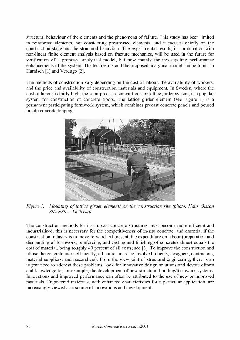
structural behaviour of the elements and the phenomena of failure. This study has been limited to reinforced elements, not considering prestressed elements, and it focuses chiefly on the construction stage and the structural behaviour. The experimental results, in combination with non-linear finite element analysis based on fracture mechanics, will be used in the future for verification of a proposed analytical model, but now mainly for investigating performance enhancements of the system. The test results and the proposed analytical model can be found in Harnisch [1] and Verdugo [2]. The methods of construction vary depending on the cost of labour, the availability of workers, and the price and availability of construction materials and equipment. In Sweden, where the cost of labour is fairly high, the semi-precast element floor, or lattice girder system, is a popular system for construction of concrete floors. The lattice girder element (see Figure 1) is a permanent participating formwork system, which combines precast concrete panels and poured in-situ concrete topping.
Figure 1. Mounting of lattice girder elements on the construction site (photo, Hans Olsson SKANSKA, Mellerud).
The construction methods for in-situ cast concrete structures must become more efficient and industrialised; this is necessary for the competitiveness of in-situ concrete, and essential if the construction industry is to move forward. At present, the expenditure on labour (preparation and dismantling of formwork, reinforcing, and casting and finishing of concrete) almost equals the cost of material, being roughly 40 percent of all costs; see [3]. To improve the construction and utilise the concrete more efficiently, all parties must be involved (clients, designers, contractors, material suppliers, and researchers). From the viewpoint of structural engineering, there is an urgent need to address these problems, look for innovative design solutions and devote efforts and knowledge to, for example, the development of new structural building/formwork systems. Innovations and improved performance can often be attributed to the use of new or improved materials. Engineered materials, with enhanced characteristics for a particular application, are increasingly viewed as a source of innovations and development.
Nordic Concrete Research, 1/2003 86
2. THE LATTICE GIRDER SYSTEM
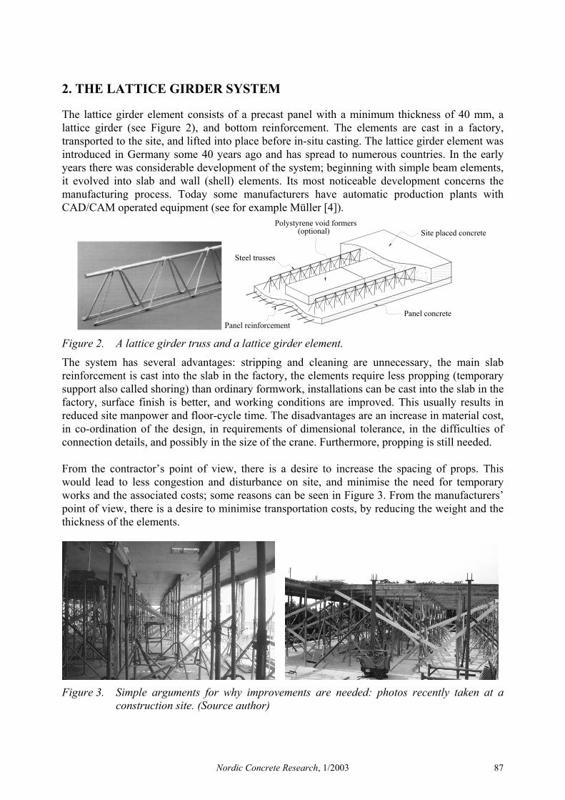
The lattice girder element consists of a precast panel with a minimum thickness of 40 mm, a lattice girder (see Figure 2), and bottom reinforcement. The elements are cast in a factory, transported to the site, and lifted into place before in-situ casting. The lattice girder element was introduced in Germany some 40 years ago and has spread to numerous countries. In the early years there was considerable development of the system; beginning with simple beam elements, it evolved into slab and wall (shell) elements. Its most noticeable development concerns the manufacturing process. Today some manufacturers have automatic production plants with CAD/CAM operated equipment (see for example Müller [4]).
Panel reinforcement
(optional)
Steel trusses
Panel concrete
Site placed concretePolystyrene void formers
Figure 2. A lattice girder truss and a lattice girder element.
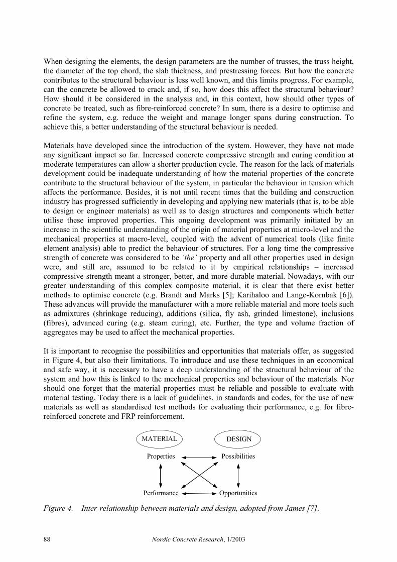
The system has several advantages: stripping and cleaning are unnecessary, the main slab reinforcement is cast into the slab in the factory, the elements require less propping (temporary support also called shoring) than ordinary formwork, installations can be cast into the slab in the factory, surface finish is better, and working conditions are improved. This usually results in reduced site manpower and floor-cycle time. The disadvantages are an increase in material cost, in co-ordination of the design, in requirements of dimensional tolerance, in the difficulties of connection details, and possibly in the size of the crane. Furthermore, propping is still needed. From the contractor’s point of view, there is a desire to increase the spacing of props. This would lead to less congestion and disturbance on site, and minimise the need for temporary works and the associated costs; some reasons can be seen in Figure 3. From the manufacturers’ point of view, there is a desire to minimise transportation costs, by reducing the weight and the thickness of the elements.
Figure 3. Simple arguments for why improvements are needed: photos recently taken at a construction site. (Source author)
Nordic Concrete Research, 1/2003 87
When designing the elements, the design parameters are the number of trusses, the truss height, the diameter of the top chord, the slab thickness, and prestressing forces. But how the concrete contributes to the structural behaviour is less well known, and this limits progress. For example, can the concrete be allowed to crack and, if so, how does this affect the structural behaviour? How should it be considered in the analysis and, in this context, how should other types of concrete be treated, such as fibre-reinforced concrete? In sum, there is a desire to optimise and refine the system, e.g. reduce the weight and manage longer spans during construction. To achieve this, a better understanding of the structural behaviour is needed. Materials have developed since the introduction of the system. However, they have not made any significant impact so far. Increased concrete compressive strength and curing condition at moderate temperatures can allow a shorter production cycle. The reason for the lack of materials development could be inadequate understanding of how the material properties of the concrete contribute to the structural behaviour of the system, in particular the behaviour in tension which affects the performance. Besides, it is not until recent times that the building and construction industry has progressed sufficiently in developing and applying new materials (that is, to be able to design or engineer materials) as well as to design structures and components which better utilise these improved properties. This ongoing development was primarily initiated by an increase in the scientific understanding of the origin of material properties at micro-level and the mechanical properties at macro-level, coupled with the advent of numerical tools (like finite element analysis) able to predict the behaviour of structures. For a long time the compressive strength of concrete was considered to be ‘the’ property and all other properties used in design were, and still are, assumed to be related to it by empirical relationships – increased compressive strength meant a stronger, better, and more durable material. Nowadays, with our greater understanding of this complex composite material, it is clear that there exist better methods to optimise concrete (e.g. Brandt and Marks [5]; Karihaloo and Lange-Kornbak [6]). These advances will provide the manufacturer with a more reliable material and more tools such as admixtures (shrinkage reducing), additions (silica, fly ash, grinded limestone), inclusions (fibres), advanced curing (e.g. steam curing), etc. Further, the type and volume fraction of aggregates may be used to affect the mechanical properties. It is important to recognise the possibilities and opportunities that materials offer, as suggested in Figure 4, but also their limitations. To introduce and use these techniques in an economical and safe way, it is necessary to have a deep understanding of the structural behaviour of the system and how this is linked to the mechanical properties and behaviour of the materials. Nor should one forget that the material properties must be reliable and possible to evaluate with material testing. Today there is a lack of guidelines, in standards and codes, for the use of new materials as well as standardised test methods for evaluating their performance, e.g. for fibre-reinforced concrete and FRP reinforcement.
MATERIAL
Properties
Performance
DESIGN
Possibilities
Opportunities
Figure 4. Inter-relationship between materials and design, adopted from James [7].
Nordic Concrete Research, 1/2003 88
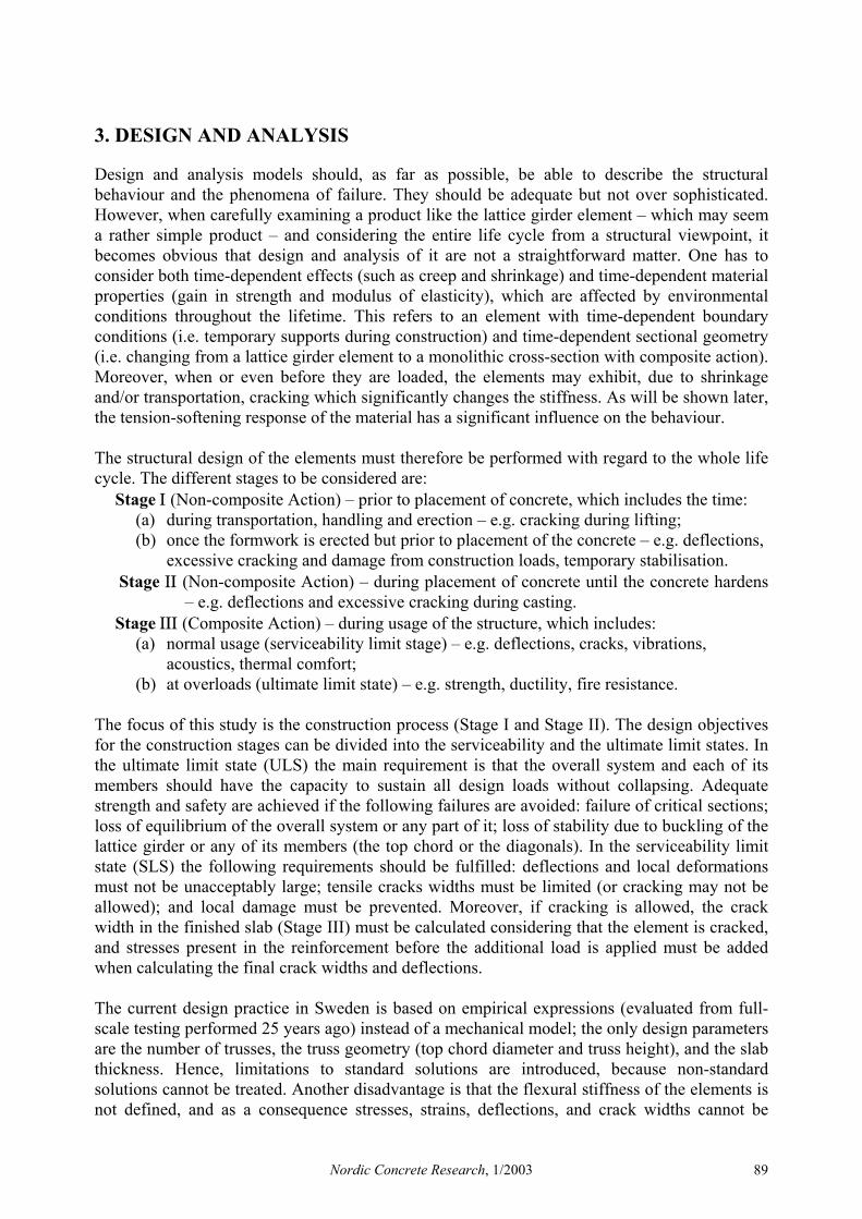
3. DESIGN AND ANALYSIS
Design and analysis models should, as far as possible, be able to describe the structural behaviour and the phenomena of failure. They should be adequate but not over sophisticated. However, when carefully examining a product like the lattice girder element – which may seem a rather simple product – and considering the entire life cycle from a structural viewpoint, it becomes obvious that design and analysis of it are not a straightforward matter. One has to consider both time-dependent effects (such as creep and shrinkage) and time-dependent material properties (gain in strength and modulus of elasticity), which are affected by environmental conditions throughout the lifetime. This refers to an element with time-dependent boundary conditions (i.e. temporary supports during construction) and time-dependent sectional geometry (i.e. changing from a lattice girder element to a monolithic cross-section with composite action). Moreover, when or even before they are loaded, the elements may exhibit, due to shrinkage and/or transportation, cracking which significantly changes the stiffness. As will be shown later, the tension-softening response of the material has a significant influence on the behaviour. The structural design of the elements must therefore be performed with regard to the whole life cycle. The different stages to be considered are:
Stage Ι (Non-composite Action) – prior to placement of concrete, which includes the time: (a) during transportation, handling and erection – e.g. cracking during lifting; (b) once the formwork is erected but prior to placement of the concrete – e.g. deflections,
excessive cracking and damage from construction loads, temporary stabilisation. Stage ΙΙ (Non-composite Action) – during placement of concrete until the concrete hardens
– e.g. deflections and excessive cracking during casting. Stage ΙΙΙ (Composite Action) – during usage of the structure, which includes:
(a) normal usage (serviceability limit stage) – e.g. deflections, cracks, vibrations, acoustics, thermal comfort;
(b) at overloads (ultimate limit state) – e.g. strength, ductility, fire resistance. The focus of this study is the construction process (Stage I and Stage II). The design objectives for the construction stages can be divided into the serviceability and the ultimate limit states. In the ultimate limit state (ULS) the main requirement is that the overall system and each of its members should have the capacity to sustain all design loads without collapsing. Adequate strength and safety are achieved if the following failures are avoided: failure of critical sections; loss of equilibrium of the overall system or any part of it; loss of stability due to buckling of the lattice girder or any of its members (the top chord or the diagonals). In the serviceability limit state (SLS) the following requirements should be fulfilled: deflections and local deformations must not be unacceptably large; tensile cracks widths must be limited (or cracking may not be allowed); and local damage must be prevented. Moreover, if cracking is allowed, the crack width in the finished slab (Stage III) must be calculated considering that the element is cracked, and stresses present in the reinforcement before the additional load is applied must be added when calculating the final crack widths and deflections. The current design practice in Sweden is based on empirical expressions (evaluated from full-scale testing performed 25 years ago) instead of a mechanical model; the only design parameters are the number of trusses, the truss geometry (top chord diameter and truss height), and the slab thickness. Hence, limitations to standard solutions are introduced, because non-standard solutions cannot be treated. Another disadvantage is that the flexural stiffness of the elements is not defined, and as a consequence stresses, strains, deflections, and crack widths cannot be
Nordic Concrete Research, 1/2003 89
calculated. Furthermore, an accurate stiffness is needed in order to calculate the shoring/propping loads in multi-storey buildings. Additionally, as mentioned, materials like fibre reinforcement are not treated in the existing design method – this is a major impediment to improving the system.
4. TEST PROGRAM
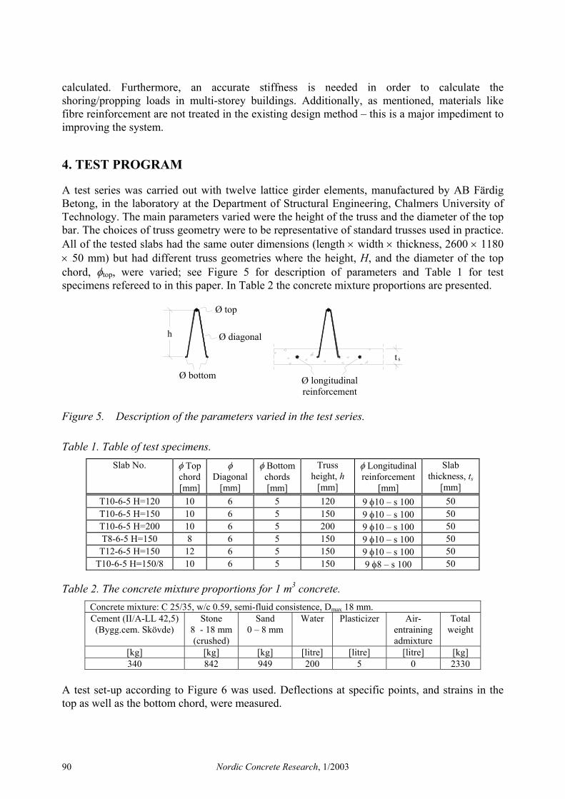
A test series was carried out with twelve lattice girder elements, manufactured by AB Färdig Betong, in the laboratory at the Department of Structural Engineering, Chalmers University of Technology. The main parameters varied were the height of the truss and the diameter of the top bar. The choices of truss geometry were to be representative of standard trusses used in practice. All of the tested slabs had the same outer dimensions (length × width × thickness, 2600 × 1180 × 50 mm) but had different truss geometries where the height, H, and the diameter of the top chord, φtop, were varied; see Figure 5 for description of parameters and Table 1 for test specimens refereed to in this paper. In Table 2 the concrete mixture proportions are presented.
Ø bottom
Ø diagonal
Ø top
Ø longitudinalreinforcement
t s
h
Figure 5. Description of the parameters varied in the test series.
Table 1. Table of test specimens. Slab No. φ Top
chord [mm]
φ Diagonal
[mm]
φ Bottom chords [mm]
Truss height, h
[mm]
φ Longitudinal reinforcement
[mm]
Slab thickness, ts
[mm] T10-6-5 H=120 10 6 5 120 9 φ10 – s 100 50 T10-6-5 H=150 10 6 5 150 9 φ10 – s 100 50 T10-6-5 H=200 10 6 5 200 9 φ10 – s 100 50 T8-6-5 H=150 8 6 5 150 9 φ10 – s 100 50
T12-6-5 H=150 12 6 5 150 9 φ10 – s 100 50 T10-6-5 H=150/8 10 6 5 150 9 φ8 – s 100 50
Table 2. The concrete mixture proportions for 1 m3 concrete. Concrete mixture: C 25/35, w/c 0.59, semi-fluid consistence, Dmax 18 mm. Cement (II/A-LL 42,5) (Bygg.cem. Skövde)
Stone 8 - 18 mm (crushed)
Sand 0 – 8 mm
Water Plasticizer
Air-entraining admixture
Total weight
[kg] [kg] [kg] [litre] [litre] [litre] [kg] 340 842 949 200 5 0 2330
A test set-up according to Figure 6 was used. Deflections at specific points, and strains in the top as well as the bottom chord, were measured.
Nordic Concrete Research, 1/2003 90

Displacementtransducers
Displacementtransducers
Displacementtransducers
Spreaderbeams
Woodenbeams
700 800 700
400 300 400 400 700
Loadcell
Hydraulicjack
Figure 6. Test set-up used in the experiments.
5. TEST RESULTS
We will now focus on the structural behaviour and discuss the mechanisms underlying it; only some of the results are presented here. For further information on the test series and the results, see Harnisch [1] and Verdugo [2].
5.1 Material Properties
Material properties were obtained from standard material tests: compressive strength on cubes, fc.cube, and cylinders, fc.cyl; splitting tensile strength on cubes, fct.sp; and modulus of elasticity on cylinders, Ec0 (see Table 3). The fracture energy, GF, was tested in an earlier experiment (see Löfgren [8]) and, since the same concrete mix was used, it was assumed that the result from this test could be used in the numerical analysis (GF = 133 Nm/m2).
Table 3. Measured material properties of the concrete, at 28 and 42 days. Material property
Age [days] 28
Age [days] 42
fc,cube [MPa] 46.5 - fct.sp [MPa] 3.6 - fc,cyl [MPa] 33.5 35.3 Ec0 [GPa] 25.1 25.6
The lattice girder truss is produced by welding cold-worked reinforcement (see Figure 2). The reinforcement in the truss was of the type Ps700, with a measured tensile strength, f0.2, of 720 MPa and measured modulus of elasticity, Es, of 210 GPa. The reinforcements used in the concrete slab were ribbed hot-rolled bars of Swedish type K500, with a measured yield strength, fy, of 586 MPa and measured modulus of elasticity, Es, of 211 GPa.
5.2 Structural Behaviour
The main drawback with concrete is the brittleness problem; cracking of concrete usually takes place at low stresses and is thus, in almost every case, inevitable in reinforced concrete
Nordic Concrete Research, 1/2003 91

elements. Large crack widths are not aesthetically appealing and may also cause initiating of reinforcement corrosion in severe environments. Furthermore, the structural behaviour is highly influenced by cracking and the cracking process, it results in a gradual reduction of the stiffness, as can be seen in Figure 7.
0
5
10
15
20
25
30
0 2 4 6 8 10 12 14 16 mid-span deflection
[mm]
Q [kN]
Micro cracking
Macro crackingPrimary cracks forming
Buckling of top-chord
A
B
C
ED
Upper limit (Elastic stiffness)
Lower limit (Stiffness of the truss)
Figure 7. Typical load–deflection curve, for slab T10-6-5 H=150.
Generally, the load-deflection behaviour is characterised by the following. The initial, almost linear relationship between load, Q, and deflection applies until the onset of macro-cracking (A). The cracks continue to grow and form as the load, Q, increases; in the load–displacement curve this is indicated in a region of decreasing stiffness (A-B). Primary cracks are primarily initiated where the diagonals intersect each other. A second near-linear range of behaviour occurs until the next set of primary cracks is formed (B-C). A third near-linear range of behaviour occurs when the crack pattern is well developed (C-D). The last stage (D-E) is reached when the top chord of the lattice girder is affected by second-order effects, which reduce the stiffness of the system; this takes place until buckling occurs and the peak load is reached (E). What is interesting with the lattice girder system is that relatively small reinforcement strains and small crack widths are introduced due to the geometrical configuration: the reinforcement is placed in the middle of the concrete slab. The crack widths are relatively small, typically < 0.1 mm at peak load and < 0.2 mm at a deflection of L0/100, and are not visible until about 60 percent of the peak load. The measured strains are typically on the order of 500-1000×10-6 at peak load, and less than 300×10-6 at 60 percent of the peak load; see Figure 10. However, the geometry of the truss (height and diameter of the top chord) influences the strain distribution in the section. For the same top chord diameter, a higher truss results in smaller strains in the bottom chord. For the same truss height, a larger top chord diameter results in larger strains in the bottom chord. As a result of the relatively small reinforcement strains and crack widths, the ability of concrete to carry tensile stresses after cracking plays a significant role for the tension-stiffening effect in the service stage. This is important for limitation of deflections, which is one of the main design parameters. The load–deflection curves are presented in Figures 8 and 9. Figure 10 shows a typical load–strain curve for the embedded truss reinforcement. Figure 11(a) shows the obtained crack pattern and 11(b) shows a deformed truss.
Nordic Concrete Research, 1/2003 92

0
5
10
15
20
25
30
35
40
45
0 5 10 15 20 25 mid-span deflection
[mm]
Q [kN]
T10-6-5 H=200
T10-6-5 H=150
T10-6-5 H=120
Figure 8. Load versus mid-span deflection, influence of the truss height.
0 5
10 15 20 25 30 35 40 45
0 5 10 15 20 25[mm]
Q [kN]
T12-6-5 H=150
T10-6-5 H=150/ φ 8
T10-6-5 H=150/ φ 10
T10-6-5 H=150
mid-span deflection
Figure 9. Load versus mid-span deflection, influence of the top chord diameter.
0
5
10
15
20
25
30
0 200 400 600 800 1000 1200 1400strain [10 -6 ]
Q [kN]
Figure 10. Typical load–strain curve for the embedded truss reinforcement, measured at mid-span, for slab T10-6-5 H=150.
Nordic Concrete Research, 1/2003 93
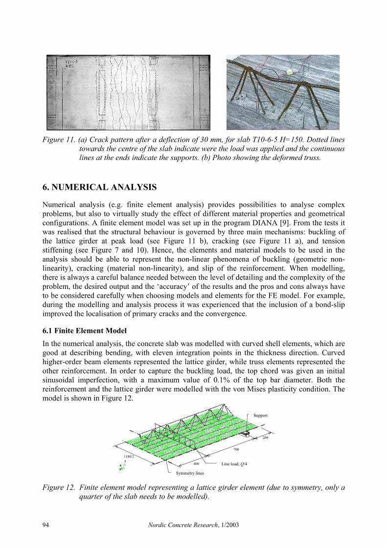
Figure 11. (a) Crack pattern after a deflection of 30 mm, for slab T10-6-5 H=150. Dotted lines towards the centre of the slab indicate were the load was applied and the continuous lines at the ends indicate the supports. (b) Photo showing the deformed truss.
6. NUMERICAL ANALYSIS
Numerical analysis (e.g. finite element analysis) provides possibilities to analyse complex problems, but also to virtually study the effect of different material properties and geometrical configurations. A finite element model was set up in the program DIANA [9]. From the tests it was realised that the structural behaviour is governed by three main mechanisms: buckling of the lattice girder at peak load (see Figure 11 b), cracking (see Figure 11 a), and tension stiffening (see Figure 7 and 10). Hence, the elements and material models to be used in the analysis should be able to represent the non-linear phenomena of buckling (geometric non-linearity), cracking (material non-linearity), and slip of the reinforcement. When modelling, there is always a careful balance needed between the level of detailing and the complexity of the problem, the desired output and the ‘accuracy’ of the results and the pros and cons always have to be considered carefully when choosing models and elements for the FE model. For example, during the modelling and analysis process it was experienced that the inclusion of a bond-slip improved the localisation of primary cracks and the convergence.
6.1 Finite Element Model
In the numerical analysis, the concrete slab was modelled with curved shell elements, which are good at describing bending, with eleven integration points in the thickness direction. Curved higher-order beam elements represented the lattice girder, while truss elements represented the other reinforcement. In order to capture the buckling load, the top chord was given an initial sinusoidal imperfection, with a maximum value of 0.1% of the top bar diameter. Both the reinforcement and the lattice girder were modelled with the von Mises plasticity condition. The model is shown in Figure 12.
Symmetry lines
Line load, Q/4
Support
1180/2
200
700
400
Figure 12. Finite element model representing a lattice girder element (due to symmetry, only a quarter of the slab needs to be modelled).
Nordic Concrete Research, 1/2003 94
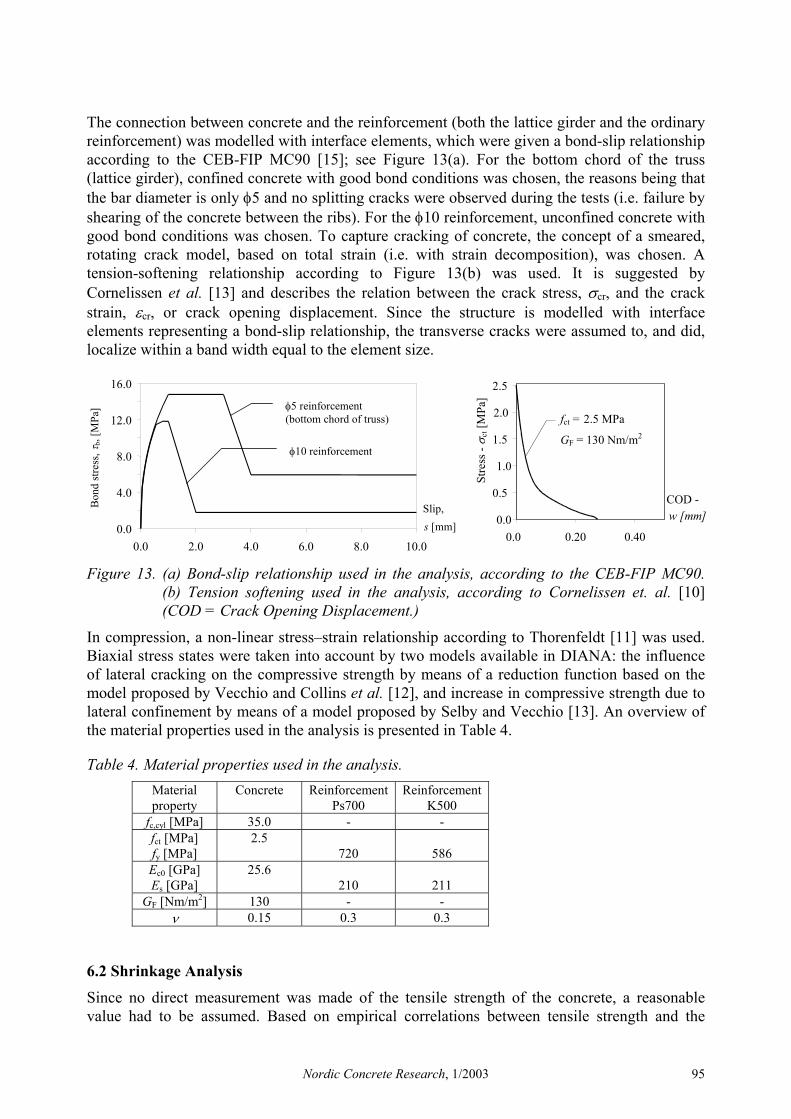
The connection between concrete and the reinforcement (both the lattice girder and the ordinary reinforcement) was modelled with interface elements, which were given a bond-slip relationship according to the CEB-FIP MC90 [15]; see Figure 13(a). For the bottom chord of the truss (lattice girder), confined concrete with good bond conditions was chosen, the reasons being that the bar diameter is only φ5 and no splitting cracks were observed during the tests (i.e. failure by shearing of the concrete between the ribs). For the φ10 reinforcement, unconfined concrete with good bond conditions was chosen. To capture cracking of concrete, the concept of a smeared, rotating crack model, based on total strain (i.e. with strain decomposition), was chosen. A tension-softening relationship according to Figure 13(b) was used. It is suggested by Cornelissen et al. [13] and describes the relation between the crack stress, σcr, and the crack strain, εcr, or crack opening displacement. Since the structure is modelled with interface elements representing a bond-slip relationship, the transverse cracks were assumed to, and did, localize within a band width equal to the element size.
0.0
4.0
8.0
12.0
16.0
0.0 2.0 4.0 6.0 8.0 10.0
Slip, s [mm]
Bon
d st
ress
, τb,
[MPa
]
φ10 reinforcement
φ5 reinforcement (bottom chord of truss)
0.0
0.5
1.0
1.5
2.0
2.5
0.0 0.20 0.40
COD - w [mm]
fct = 2.5 MPa
GF = 130 Nm/m2
Stre
ss -
σ ct [
MPa
]
Figure 13. (a) Bond-slip relationship used in the analysis, according to the CEB-FIP MC90. (b) Tension softening used in the analysis, according to Cornelissen et. al. [10] (COD = Crack Opening Displacement.)
In compression, a non-linear stress–strain relationship according to Thorenfeldt [11] was used. Biaxial stress states were taken into account by two models available in DIANA: the influence of lateral cracking on the compressive strength by means of a reduction function based on the model proposed by Vecchio and Collins et al. [12], and increase in compressive strength due to lateral confinement by means of a model proposed by Selby and Vecchio [13]. An overview of the material properties used in the analysis is presented in Table 4.
Table 4. Material properties used in the analysis. Material property
Concrete Reinforcement Ps700
Reinforcement K500
fc,cyl [MPa] 35.0 - - fct [MPa] fy [MPa]
2.5 720
586
Ec0 [GPa] Es [GPa]
25.6 210
211
GF [Nm/m2] 130 - - ν 0.15 0.3 0.3
6.2 Shrinkage Analysis
Since no direct measurement was made of the tensile strength of the concrete, a reasonable value had to be assumed. Based on empirical correlations between tensile strength and the
Nordic Concrete Research, 1/2003 95
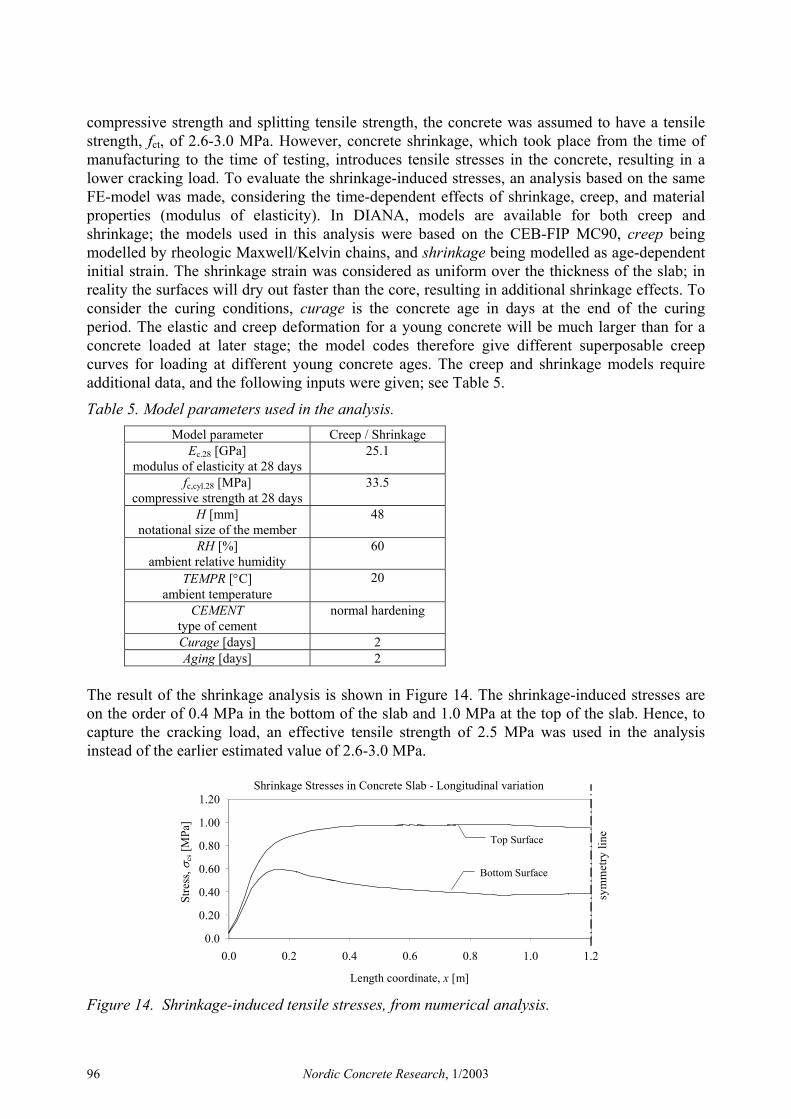
compressive strength and splitting tensile strength, the concrete was assumed to have a tensile strength, fct, of 2.6-3.0 MPa. However, concrete shrinkage, which took place from the time of manufacturing to the time of testing, introduces tensile stresses in the concrete, resulting in a lower cracking load. To evaluate the shrinkage-induced stresses, an analysis based on the same FE-model was made, considering the time-dependent effects of shrinkage, creep, and material properties (modulus of elasticity). In DIANA, models are available for both creep and shrinkage; the models used in this analysis were based on the CEB-FIP MC90, creep being modelled by rheologic Maxwell/Kelvin chains, and shrinkage being modelled as age-dependent initial strain. The shrinkage strain was considered as uniform over the thickness of the slab; in reality the surfaces will dry out faster than the core, resulting in additional shrinkage effects. To consider the curing conditions, curage is the concrete age in days at the end of the curing period. The elastic and creep deformation for a young concrete will be much larger than for a concrete loaded at later stage; the model codes therefore give different superposable creep curves for loading at different young concrete ages. The creep and shrinkage models require additional data, and the following inputs were given; see Table 5.
Table 5. Model parameters used in the analysis. Model parameter Creep / Shrinkage
Ec.28 [GPa] modulus of elasticity at 28 days
25.1
fc,cyl.28 [MPa] compressive strength at 28 days
33.5
H [mm] notational size of the member
48
RH [%] ambient relative humidity
60
TEMPR [°C] ambient temperature
20
CEMENT type of cement
normal hardening
Curage [days] 2 Aging [days] 2
The result of the shrinkage analysis is shown in Figure 14. The shrinkage-induced stresses are on the order of 0.4 MPa in the bottom of the slab and 1.0 MPa at the top of the slab. Hence, to capture the cracking load, an effective tensile strength of 2.5 MPa was used in the analysis instead of the earlier estimated value of 2.6-3.0 MPa.
Shrinkage Stresses in Concrete Slab - Longitudinal variation
0.0
0.20
0.40
0.60
0.80
1.00
1.20
0.0 0.2 0.4 0.6 0.8 1.0 1.2
Length coordinate, x [m]
Stre
ss,
σ cs [
MPa
]
Top Surface
Bottom Surface
sym
met
ry li
ne
Figure 14. Shrinkage-induced tensile stresses, from numerical analysis.
Nordic Concrete Research, 1/2003 96
6.3 Results From Numerical Analysis
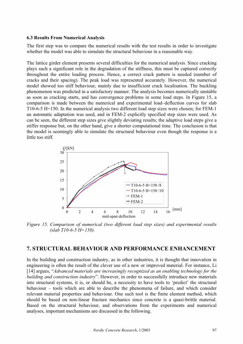
The first step was to compare the numerical results with the test results in order to investigate whether the model was able to simulate the structural behaviour in a reasonable way. The lattice girder element presents several difficulties for the numerical analysis. Since cracking plays such a significant role in the degradation of the stiffness, this must be captured correctly throughout the entire loading process. Hence, a correct crack pattern is needed (number of cracks and their spacing). The peak load was represented accurately. However, the numerical model showed too stiff behaviour, mainly due to insufficient crack localisation. The buckling phenomenon was predicted in a satisfactory manner. The analysis becomes numerically unstable as soon as cracking starts, and has convergence problems in some load steps. In Figure 15, a comparison is made between the numerical and experimental load–deflection curves for slab T10-6-5 H=150. In the numerical analysis two different load step sizes were chosen; for FEM-1 an automatic adaptation was used, and in FEM-2 explicitly specified step sizes were used. As can be seen, the different step sizes give slightly deviating results; the adaptive load steps give a stiffer response but, on the other hand, give a shorter computational time. The conclusion is that the model is seemingly able to simulate the structural behaviour even though the response is a little too stiff.
0
5
10
15
20
25
30
0 2 4 6 8 10 12 14 16 mid-span deflection
[mm]
Q [kN]
T10-6-5 H=150 /8
T10-6-5 H=150 /10
FEM-1
FEM-2
Figure 15. Comparison of numerical (two different load step sizes) and experimental results (slab T10-6-5 H=150).
7. STRUCTURAL BEHAVIOUR AND PERFORMANCE ENHANCEMENT
In the building and construction industry, as in other industries, it is thought that innovation in engineering is often the result of the clever use of a new or improved material. For instance, Li [14] argues, “Advanced materials are increasingly recognized as an enabling technology for the building and construction industry”. However, in order to successfully introduce new materials into structural systems, it is, or should be, a necessity to have tools to ‘predict’ the structural behaviour – tools which are able to describe the phenomena of failure, and which consider relevant material properties and behaviour. One such tool is the finite element method, which should be based on non-linear fracture mechanics since concrete is a quasi-brittle material. Based on the structural behaviour, and observations from the experiments and numerical analyses, important mechanisms are discussed in the following.
Nordic Concrete Research, 1/2003 97
7.1 Cracking and Tension Softening
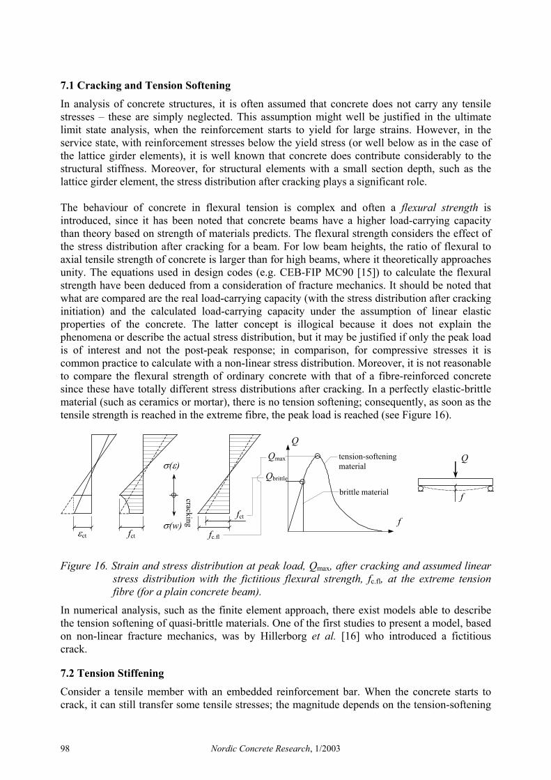
In analysis of concrete structures, it is often assumed that concrete does not carry any tensile stresses – these are simply neglected. This assumption might well be justified in the ultimate limit state analysis, when the reinforcement starts to yield for large strains. However, in the service state, with reinforcement stresses below the yield stress (or well below as in the case of the lattice girder elements), it is well known that concrete does contribute considerably to the structural stiffness. Moreover, for structural elements with a small section depth, such as the lattice girder element, the stress distribution after cracking plays a significant role. The behaviour of concrete in flexural tension is complex and often a flexural strength is introduced, since it has been noted that concrete beams have a higher load-carrying capacity than theory based on strength of materials predicts. The flexural strength considers the effect of the stress distribution after cracking for a beam. For low beam heights, the ratio of flexural to axial tensile strength of concrete is larger than for high beams, where it theoretically approaches unity. The equations used in design codes (e.g. CEB-FIP MC90 [15]) to calculate the flexural strength have been deduced from a consideration of fracture mechanics. It should be noted that what are compared are the real load-carrying capacity (with the stress distribution after cracking initiation) and the calculated load-carrying capacity under the assumption of linear elastic properties of the concrete. The latter concept is illogical because it does not explain the phenomena or describe the actual stress distribution, but it may be justified if only the peak load is of interest and not the post-peak response; in comparison, for compressive stresses it is common practice to calculate with a non-linear stress distribution. Moreover, it is not reasonable to compare the flexural strength of ordinary concrete with that of a fibre-reinforced concrete since these have totally different stress distributions after cracking. In a perfectly elastic-brittle material (such as ceramics or mortar), there is no tension softening; consequently, as soon as the tensile strength is reached in the extreme fibre, the peak load is reached (see Figure 16).
fc.fl fct
σ(ε)
σ(w) εct
fct
cracking
QQmax
Qbrittle
tension-softening material
brittle material f
Q
f
Figure 16. Strain and stress distribution at peak load, Qmax, after cracking and assumed linear stress distribution with the fictitious flexural strength, fc.fl, at the extreme tension fibre (for a plain concrete beam).
In numerical analysis, such as the finite element approach, there exist models able to describe the tension softening of quasi-brittle materials. One of the first studies to present a model, based on non-linear fracture mechanics, was by Hillerborg et al. [16] who introduced a fictitious crack.
7.2 Tension Stiffening
Consider a tensile member with an embedded reinforcement bar. When the concrete starts to crack, it can still transfer some tensile stresses; the magnitude depends on the tension-softening
Nordic Concrete Research, 1/2003 98
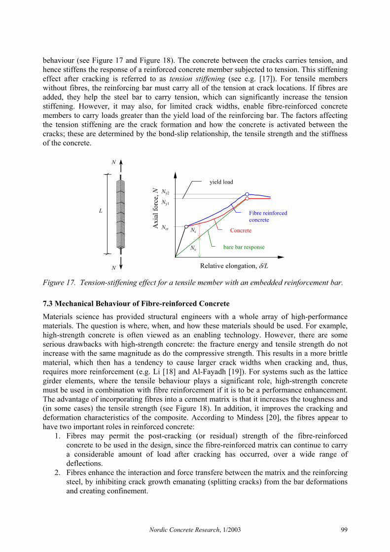
behaviour (see Figure 17 and Figure 18). The concrete between the cracks carries tension, and hence stiffens the response of a reinforced concrete member subjected to tension. This stiffening effect after cracking is referred to as tension stiffening (see e.g. [17]). For tensile members without fibres, the reinforcing bar must carry all of the tension at crack locations. If fibres are added, they help the steel bar to carry tension, which can significantly increase the tension stiffening. However, it may also, for limited crack widths, enable fibre-reinforced concrete members to carry loads greater than the yield load of the reinforcing bar. The factors affecting the tension stiffening are the crack formation and how the concrete is activated between the cracks; these are determined by the bond-slip relationship, the tensile strength and the stiffness of the concrete.
Relative elongation, δ/L
Axi
al fo
rce,
N
bare bar response
Ncr
Ny1
Ny2
N
N
L
Ns
Nc
Fibre reinforced concrete
Concrete
yield load
Figure 17. Tension-stiffening effect for a tensile member with an embedded reinforcement bar.
7.3 Mechanical Behaviour of Fibre-reinforced Concrete
Materials science has provided structural engineers with a whole array of high-performance materials. The question is where, when, and how these materials should be used. For example, high-strength concrete is often viewed as an enabling technology. However, there are some serious drawbacks with high-strength concrete: the fracture energy and tensile strength do not increase with the same magnitude as do the compressive strength. This results in a more brittle material, which then has a tendency to cause larger crack widths when cracking and, thus, requires more reinforcement (e.g. Li [18] and Al-Fayadh [19]). For systems such as the lattice girder elements, where the tensile behaviour plays a significant role, high-strength concrete must be used in combination with fibre reinforcement if it is to be a performance enhancement. The advantage of incorporating fibres into a cement matrix is that it increases the toughness and (in some cases) the tensile strength (see Figure 18). In addition, it improves the cracking and deformation characteristics of the composite. According to Mindess [20], the fibres appear to have two important roles in reinforced concrete:
1. Fibres may permit the post-cracking (or residual) strength of the fibre-reinforced concrete to be used in the design, since the fibre-reinforced matrix can continue to carry a considerable amount of load after cracking has occurred, over a wide range of deflections.
2. Fibres enhance the interaction and force transfere between the matrix and the reinforcing steel, by inhibiting crack growth emanating (splitting cracks) from the bar deformations and creating confinement.
Nordic Concrete Research, 1/2003 99
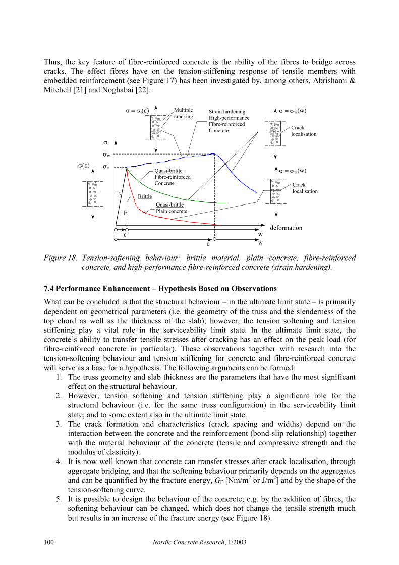
Thus, the key feature of fibre-reinforced concrete is the ability of the fibres to bridge across cracks. The effect fibres have on the tension-stiffening response of tensile members with embedded reinforcement (see Figure 17) has been investigated by, among others, Abrishami & Mitchell [21] and Noghabai [22].
w ε
deformation
σε
σ
E
σ(ε)
σ = σt(ε)
σw
Quasi-brittle Plain concrete
Quasi-brittle Fibre-reinforced Concrete
Strain hardening: High-performance Fibre-reinforced Concrete
σ = σw(w)
w ε
Multiple cracking
σ = σw(w)
Crack localisation
Crack localisation
Brittle
Figure 18. Tension-softening behaviour: brittle material, plain concrete, fibre-reinforced concrete, and high-performance fibre-reinforced concrete (strain hardening).
7.4 Performance Enhancement – Hypothesis Based on Observations
What can be concluded is that the structural behaviour – in the ultimate limit state – is primarily dependent on geometrical parameters (i.e. the geometry of the truss and the slenderness of the top chord as well as the thickness of the slab); however, the tension softening and tension stiffening play a vital role in the serviceability limit state. In the ultimate limit state, the concrete’s ability to transfer tensile stresses after cracking has an effect on the peak load (for fibre-reinforced concrete in particular). These observations together with research into the tension-softening behaviour and tension stiffening for concrete and fibre-reinforced concrete will serve as a base for a hypothesis. The following arguments can be formed:
1. The truss geometry and slab thickness are the parameters that have the most significant effect on the structural behaviour.
2. However, tension softening and tension stiffening play a significant role for the structural behaviour (i.e. for the same truss configuration) in the serviceability limit state, and to some extent also in the ultimate limit state.
3. The crack formation and characteristics (crack spacing and widths) depend on the interaction between the concrete and the reinforcement (bond-slip relationship) together with the material behaviour of the concrete (tensile and compressive strength and the modulus of elasticity).
4. It is now well known that concrete can transfer stresses after crack localisation, through aggregate bridging, and that the softening behaviour primarily depends on the aggregates and can be quantified by the fracture energy, GF [Nm/m2 or J/m2] and by the shape of the tension-softening curve.
5. It is possible to design the behaviour of the concrete; e.g. by the addition of fibres, the softening behaviour can be changed, which does not change the tensile strength much but results in an increase of the fracture energy (see Figure 18).
Nordic Concrete Research, 1/2003 100
6. For fibre-reinforced concrete, it is known that the type of fibre (material properties, length, diameter, surface characteristics, etc.) and the volume fraction, as well as the type of the matrices it is embedded in, have a significant impact on the softening behaviour.
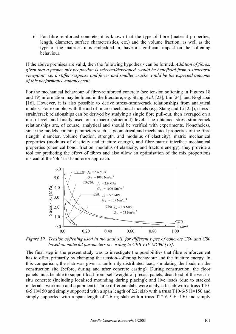
If the above premises are valid, then the following hypothesis can be formed. Addition of fibres, given that a proper mix proportion is selected/developed, would be beneficial from a structural viewpoint; i.e. a stiffer response and fewer and smaller cracks would be the expected outcome of this performance enhancement. For the mechanical behaviour of fibre-reinforced concrete (see tension softening in Figures 18 and 19) information may be found in the literature, e.g. Stang et al. [23], Lin [24], and Noghabai [16]. However, it is also possible to derive stress–strain/crack relationships from analytical models. For example, with the aid of micro-mechanical models (e.g. Stang and Li [25]), stress–strain/crack relationships can be derived by studying a single fibre pull-out, then averaged on a meso level, and finally used on a macro (structural) level. The obtained stress-strain/crack relationships are, of course, analytical and should be verified with experiments. Nonetheless, since the models contain parameters such as geometrical and mechanical properties of the fibre (length, diameter, volume fraction, strength, and modulus of elasticity), matrix mechanical properties (modulus of elasticity and fracture energy), and fibre-matrix interface mechanical properties (chemical bond, friction, modulus of elasticity, and fracture energy), they provide a tool for predicting the effect of fibres and also allow an optimisation of the mix proportions instead of the ‘old’ trial-and-error approach.
0.0
1.0
2.0
3.0
4.0
5.0
6.0
0.0 0.20 0.40 0.60 0.80 1.00
COD - w [mm]
Stre
ss -
σ ct [
MPa
] fct = 2.9 MPaG F = 1000 Nm/m 2
f ct = 5.6 MPaG F = 1000 Nm/m 2
fct = 2.9 MPaG F = 75 Nm/m 2
fct = 5.6 MPaG F = 135 Nm/m 2
FRC80:
FRC30:
C80:
C30:
Figure 19. Tension softening used in the analysis, for different types of concrete C30 and C80 based on material parameters according to CEB-FIP MC90 [15].
The final step in the present study was to investigate the possibilities that fibre reinforcement has to offer, primarily by changing the tension-softening behaviour and the fracture energy. In this comparison, the slab was given a uniformly distributed load, simulating the loads on the construction site (before, during and after concrete casting). During construction, the floor panels must be able to support load from: self-weight of precast panels; dead load of the wet in-situ concrete (including localised mounding during placing); and live loads (due to stacked materials, workmen and equipment). Three different slabs were analysed: slab with a truss T10-6-5 H=150 and simply supported with a span length of 2.2; slab with a truss T10-6-5 H=150 and simply supported with a span length of 2.6 m; slab with a truss T12-6-5 H=150 and simply
Nordic Concrete Research, 1/2003 101
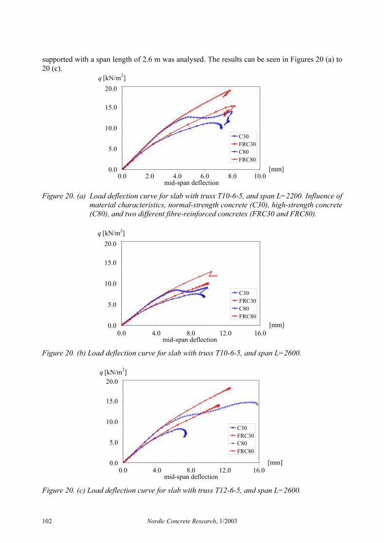
supported with a span length of 2.6 m was analysed. The results can be seen in Figures 20 (a) to 20 (c).
0.0
5.0
10.0
15.0
20.0
0.0 2.0 4.0 6.0 8.0 10.0 mid-span deflection
[mm]
q [kN/m 2 ]
C30
FRC30
C80
FRC80
Figure 20. (a) Load deflection curve for slab with truss T10-6-5, and span L=2200. Influence of
material characteristics, normal-strength concrete (C30), high-strength concrete (C80), and two different fibre-reinforced concretes (FRC30 and FRC80).
0.0
5.0
10.0
15.0
20.0
0.0 4.0 8.0 12.0 16.0 mid-span deflection
[mm]
q [kN/m2]
C30
FRC30
C80
FRC80
Figure 20. (b) Load deflection curve for slab with truss T10-6-5, and span L=2600.
0.0
5.0
10.0
15.0
20.0
0.0 4.0 8.0 12.0 16.0 mid-span deflection
[mm]
q [kN/m 2 ]
C30
FRC30
FRC80
C80
Figure 20. (c) Load deflection curve for slab with truss T12-6-5, and span L=2600.
Nordic Concrete Research, 1/2003 102

The numerical analyses suggest that the toughness, which the addition of fibres produces, plays a significant role for the structural behaviour, both for the serviceability- (limiting deflections) and the ultimate limit state. The stiffness of the system, after cracking, is increased and it is thus able to carry a larger load at the same deflection; this is more pronounced for the high-strength concrete. Furthermore, the peak load is increased, even though the top chord buckles at the same stress, since the concrete is able to participate in the load-carrying capacity. The crack formation differed between the normal-strength concrete and the high-strength concrete, with fewer cracks forming for the high-strength concrete. The increased modulus of elasticity of the high-strength concrete significantly increases the stiffness of the system. However, when cracks are initiated this results in a rapid degradation of the stiffness, and the top chord now has to carry a larger compressive force in order to balance the bending moment. Furthermore, as cracking is initiated for a rather high load, almost the same as the peak load, the behaviour becomes brittle. The increased toughness seems to be of particular importance for the high-strength concrete where the crack initiation leads to a rapid stiffness reduction.
8. CONCLUSIONS
This investigation has shown that with numerical tools it is possible to virtually study the effects of different materials on the structural behaviour of the system. The study was limited to simulating the effect, within certain geometrical configurations, on four types of concrete: normal-strength, high-strength, fibre-reinforced normal-strength, and fibre-reinforced high-strength. The structural behaviour of the lattice girder element is, above all, affected by the geometrical configuration of the lattice girder. However, tension stiffening as well as the tension softening of the concrete has a substantial influence on the structural behaviour. Further:
1. The results of the numerical analyses show that it is possible to analyse lattice girder elements. It is essential, though, to use a model able to describe the tension softening of the concrete and to obtain a reasonable crack pattern.
2. A bigger top chord bar increases, as expected, the stiffness and the peak load. 3. An increased modulus of elasticity of the concrete increases the stiffness of the elements. 4. A tougher concrete, which the addition of fibres produces, may increase both the peak
load and the stiffness of the elements. 5. The increased toughness seems to be particularly important for the high-strength
concrete, where the crack initiation leads to a rapid stiffness reduction. Lattice girder elements could be one interesting application for fibre-reinforced concrete and, with the opportunities that exist today for designing materials, an appropriate mix proportion should not be impossible to develop. Based on a deep understanding of the structural behaviour, the link between structural behaviour and material properties/behaviour can be used to optimise the structural performance. Moreover, when the mechanisms behind the structural behaviour have been identified, the design optimisation to achieve the desired performance of the product can be realised by optimising both the geometry and the properties of the materials used. However, this study has so far been limited to the construction stage, and only the performance in this case has been investigated for a single-span element. A complete investigation of the entire life cycle is needed for a genuine optimisation of the system, as described in Chapter 3. Furthermore, improved engineered materials require additional studies and a closer collaboration with materials scientists.
Nordic Concrete Research, 1/2003 103

9. REFERENCES [1] Harnisch, J.: Comparative Studies on Lattice Girder Elements (Full-scale tests and a finite element simulation), Master’s Thesis 01:13, Dept. of Structural Engineering – Concrete Structures, Chalmers University of Technology, Göteborg, Sweden, 2001, 81 pp. [2] Verdugo, G.: Full-scale Tests and Analytical Model for Lattice Girder Elements, Master’s Thesis 01:11, Dept. of Structural Engineering – Concrete Structures, Chalmers University of Technology, Göteborg, Sweden, 2001, 53 pp. [3] Löfgren, I. and Gylltoft, K.: In-situ cast concrete building: Important aspects of industrialised construction , Nordic Concrete Research, 1/2001, 2001, pp. 61-81. [4] Müller, J. P.: Element or Lattice Girder Floors – Conventionally Reinforced and Prestressed – with Costing Examples, Betonwerk + Fertigteil-Technik, BFT 4/1991, pp. 44-50. [5] Brandt, A. M. and Marks, M.: Optimization of the Material Structure and Composition of Cement Based Composites, Cement and Concrete Composites, 18 (1996), Elsevier, pp. 271-279. [6] Karihaloo, B. L. and Lange-Kornbak, D.: Optimization techniques for the design of high-performance fibre-reinforced concrete, Struct Multidisc Optim 21 (2001), Springer-Verlag, pp. 32-39. [7] James, M. N.: Engineering Materialism and Structural Integrity, Journal of Engineering Design, Vol. 9, No. 4, CARFAX, pp. 329-342. [8] Löfgren, I.: Lattice Girder Elements in Four Point Bending – Pilot Experiment, Report No. 01:7, Dept. of Structural Engineering – Concrete Structures, Chalmers University of Technology, Göteborg, Sweden, 2001. [9] TNO Building and Construction Research: DIANA Finite Element Analysis, User’s Manual 7. Deen Haag, 1998. [10] Cornelissen, H. A. W., Hordijk, D. A., and Reinhardt, H. W.: Experimental determination of crack softening characteristics of normalweight and lightweight concrete. Heron 31, 2 (1986). [11] Thorenfeldt, E., Tomaszewicz, A., and Jensen, J. J.: Mechanical properties of high-strength concrete and applications in design. In Proc. Symp. Utilization of High-Strength Concrete (Stavanger, Norway) (Trondheim, 1987), Tapir. [12]Vecchio, F. J. and Collins, M. P.: Compression Response of Cracked Reinforced Concrete. J. Str. Eng., ASCE 119, 12 (1993), pp. 3590-3610. [13] Selby, R. G. and Vecchio, F. J.: Three-dimensional Constitutive Relations for Reinforced Concrete. Tech. Rep. 93-02, Dept. of Civil Eng., Univ. of Toronto, Toronto, Canada, 1993. [14] Li, V. C.: From Micromechanics to Structural Engineering – The design of cementitious composites for civil engineering applications, Structural Eng. / Earthquake Eng. Vol. 10, No. 2, July 1993, pp. 37-48. [15] CEB-FIP Model Code 1990: Bulletin d’information 213/214. Lausanne, Switzerland, May 1993, 437 pp. [16] Hillerborg, A., Modéer, M. and Petersson, P-E.: Analysis of crack formation and crack growth in concrete by means of fracture mechanics and finite elements, Cement and Concrete Research, Vol. 6 (1976), pp. 773-782. [17] CEB Bulletin d’Information 235: Serviceability Models – Behaviour And Modelling In Serviceability Limit States Including Repeated And Sustained Loads. Progress report, April 1997, Lausanne, Switzerland, 265 pp. [18] Li, V.C.: Technological Implications of Concrete Fracture Research – An Overview of Tensile Failure in Cementitious Materials and Structures, in Fracture Mechanics : Application to Concrete, Eds. V.C. Li and Z. Bazant, ACI SP-118, pp. 1-16, 1989. [19] Al-Fayadh, S.: Cracking Behaviour of Reinforced Concrete Tensile Members, Master’s Thesis 97:3, Dept. of Structural Engineering – Division of Concrete Structures, Chalmers University of Technology, Göteborg, Sweden 1997. [20] Mindess, S.: Fiber Reinforced Concrete: Challenges and Prospects, in Fiber Reinforced Concrete, Eds. N. Banthia and S. Mindess, Second University-Industry Workshop on Fiber Reinforced Concrete and other Advanced Composites, Toronto, Canada, March 26-29, 1995. [21] Abrishami, H. H. and Mitchell, D.: Influence of steel fibers on tension stiffening, ACI Structural Journal, Vol. 94, No. 6, Nov-Dec 1997, pp. 769-776. [22] Noghabai, K.: Effect of tension softening on the performance of concrete structures – experimental, analytical and computational studies, PhD thesis 1998:21, Luleå University of Technology, Luleå, Sweden, 1998, 147 pp. [23] Stang, H., Li, V. C. and Krenchel, H.: Design and structural application of stress–crack width relations in fibre reinforced concrete, Materials and Structures, 28, 1995, pp. 210-219. [24] Lin, Y-Z.: Tragverhalten von Stahlfaserbeton, Deutscher Ausschuss für Stahlbeton, Heft 494, Berlin, 1999. [25] Stang, H. and Li, V. C.: Mechanics of Fibre Reinforced Cement Based Composites, International Graduate Research School in Applied Mechanics, course material, Lyngby, Denmark 2001.
Nordic Concrete Research, 1/2003 104