large utility oiler design onsiderations for ycling and ... · pdf filefriends who operate...
TRANSCRIPT
This informational newsletter is written for our
friends who operate large utility boilers that
were originally designed for base load operation
at loads from 60% to 100% MCR (Maximum Con-
tinuous Rating). There are some concerns that
many engineers have not thought about for
many years. In the early years of my career I was
employed as a startup engineer. When new 300-
500 MW coal units were started up we were vigi-
lant in watching for superheater clearing of con-
densate, using furnace startup probes to make
certain the furnace exit gases did not exceed
1,000°F before the turbine was synchronized and
reheater flows were established. Also we were
cognizant of the very low superheater and re-
heater pressure drops at low loads.
Why? Because of such common factors as water
plugging of non-drainable pendant tubes and
possible overheating of select circuits due to une-
qual flows of steam through the superheater and
reheater on the steam side and also non uniform
flue gas temperatures on the fire-side. It has
come to our attention that current operations of
the existing coal fleet, designed in the 1970’s and
1980’s is being operated at conditions the large
utility boilers were not designed for.
STORM TECHNOLOGIES, INC. July 2015
Large Utility Boiler Design Considerations for Cycling and Low Load Operation
These base load designed units are being cycled off
on weekends and operated at low loads at nights.
This is what it takes to competitively generate power
to supply the “grid” for best economic dispatch.
Page 1
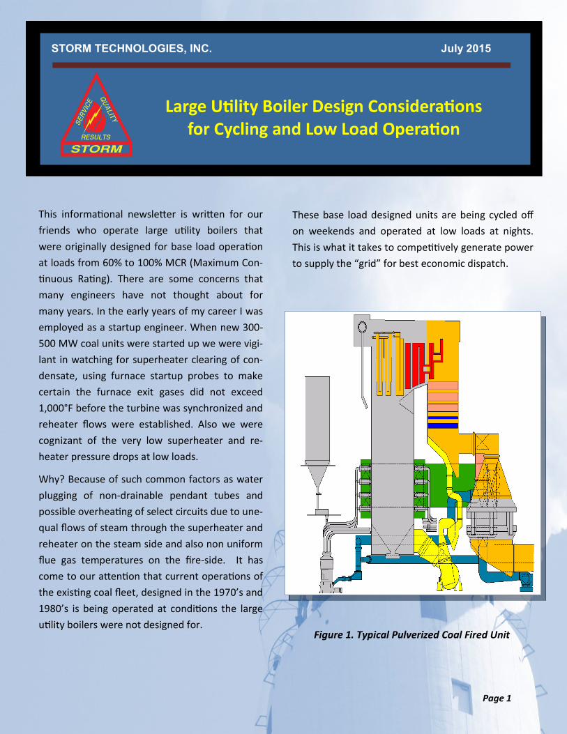
Figure 1. Typical Pulverized Coal Fired Unit

The situation today requires more cycling and low load operation for at least four reasons:
America’s 24/7 industrial demand is less now than it was in the 1980’s so, loads at nights and weekends are much lower with more commercial and residential load to-day, less primary metals production and other heavy manufacturing that we en-joyed thirty years ago.
Must run renewable wind turbines come onto the Grid when the wind blows and often this is at the time of day that it is not needed. The result, backing down of the coal plant loads, even shutting the plants down overnight.
Low cost natural gas combined cycle units in some cases have replaced the “Base load” capacity of 300-500 MW pulverized coal units. The coal plants in some cases are taking the swing load demand of the Grid.
The nuclear units which make up about 20% of America’s generation fleet continue to operate as base load
Those of us involved in the operations and maintenance of large coal units cannot do anything about the external business pres-sures that subject our pride and joy, large coal units, to such abuse but we can be aware of the design details and do our best to work around a difficult situation. This newsletter is being written in July, a time of reasonably high summer power demand. In a few months it will be fall, bringing cooler weather and the night-time and weekend power de-mand even lower. So, the problems created by low load operation and cycling are likely to persist for years. The best we can do is to re-view the design principles of large utility boil-er superheaters and reheaters and the weak-nesses that are exposed by low load opera-tions. Once the weaknesses are identified, there are some operations and maintenance procedures and techniques that can be used to further protect these important assets.
Let me use a wall-fired B&W 2,400 psi, 1,000/1,000° F. RB Boiler as an example. This is a boiler rated at 360 MW and is typical of many units designed in the 1980’s.
Page 2
Table 1: Unit Design Data
MCR Steam Flow 2,510, 000 pounds per hour
Superheater Outlet Design Temperature
1,005 ° F.
Reheater Outlet Design Temperature
1,005° F.
Guaranteed Superheater Differential at MCR
189 psi (Drum to SH outlet) This is pressure differential all three
sections of the superheater
Guaranteed Reheater Differential
25 psi
Figure 2. Wall-Fired Boiler Arrangement
Note: The superheater and reheater guaranteed pres-sure drops are just that, guaranteed. The actual de-sign calculated pressure drops are less than the design to make certain the guaranteed pressure drops are not exceeded. These design pressure drops are:
Superheater total design pressure drop – 157.8 psi
Reheater design pressure drop—18 psi
The total 18 psi pressure drop includes 3 psi for the pipes and headers. The tube bank pressure drop de-sign is only about 15 psi at MCR.

The data presented above is all for MCR. The con-cern of this message is, what happens when units designed such as this example are subjected to very low loads and firing rates?
The pressure drop of superheaters and reheaters basically follow the “square law,” that is, at 25% load, the pressure drop if the steam had the same properties, specific volume and temperature, would be 1/16th of MCR when the load is reduced to 25% of MCR. From the above, it is apparent that the total superheater pressure drop will be in the range of 10 psi at 25% load and about 1.5 psi at 10% load.
The reheater will be far less at about 1.1 psi. At 10% load the reheater differential is well less than 1 psi. One key point is, if the contract design guar-antees are consulted, remember the design engi-neers that originally designed the boiler surfaces, actually designed some margin into these to make absolutely certain that the guaranteed pressure drops were not exceeded.
It is even worse for the superheater when the differentials through the pendant, non-drainable tubes is considered. The total design pressure drop of about 158 psi is for all three superheater sections. When low loads are considered for the pendant superheaters alone, then the differential at startup or low load operation is single digits or less. For this boiler in the example, the finishing SSH (secondary superheater) differential is de-signed to be as follows:
Platen SH 9.8 psi SSH Inlet Bank 14.7 psi SSH Outlet Bank 56.2 psi
The platen SH and SSH are located at the furnace exit. When firing coal with two lower rows of burn-ers in service, this zone of the furnace will be at a temperature of about 1,200°F-1,500°F at minimum loads of say 10-25% of MCR. The pressure differen-tial will be less than 1 psi at about 15% load. This is the total head available to distribute the steam-flows to all tube circuits and to lift any accumulated condensate.
The preceding represents the steam side pressure drops at high and low loads. Now, let's consider the fire-side. As a large coal unit is started up the FEGT (Furnace Exit Gas Temperature) will be maintained in accordance with standard SH and RH protective practices, at a temperature below 1,000°F for re-heater and superheater tube metals protection. It is customary on many large units I have experience with, that as soon as the turbine-generator is syn-chronized and load increased, it requires the start of a pulverizer to provide sufficient fuel to increase load from 10% to say 25% of turbine load. In my experi-ence for a typical large coal unit, as soon as the first pulverizer is put into operation, the FEGT will make a step change from about 1,000°F to the range of 1,200°F to 1,600°F.
Page 3
All of the superheater components from the
Drum to the SSH Outlet including connecting
piping, attemperators, PSH, Furnace Platens, SSH
and drum dry pan: 157.8 psi
Figure 3. SSH Differential Pressure vs. Percent Load
of MCR

Of course this depends somewhat on the specific type of unit (wall-fired, corner-fired, turbo, cy-clone) and other factors such as total airflow, idle burner air registers open, etc. The point is, at very low loads, the FEGT will be in the range of 1,200°F-1,600°F. The superheater and reheater metals most likely have maximum limits well be-low 1,150°F. Therefore, the potential for over-heating of the metals exists at low loads as much as it does at high loads. Even if natural gas fuel is utilized for loads between 10% and 25% the FEGT is likely to be well above 1,200°F due to the fact that gas flames have less radiant heat release or emissivity for a given heat input. For operation at lower than 5 psi SH and RH differential pressures it is recommended that the SH and RH tube metal thermocouples and furnace exit gas measure-ments be monitored to make certain some select tube circuits are not being overheated.
© STI, Storm Technologies, Inv. – All Rights Reserved
Page 4
Figure 4. FEGT vs. Percent Load of MCR
Table 2: Maximum Allowable Metal Temperatures for Common Alloys
What about “Water-Plugging” of Circuits?
I have not heard the term water plugging or clearing of SH tubes for years. The foregoing discusses low pressure drops at low loads and the flue gas temper-atures that are common at 10-25% of MCR loads. Getting back to the “steam-side” conditions, here is a reminder of the water-plugging situation that can contribute to the problem for tube metals over-heating.
Think about the platen SH and the SSH superheater when a boiler MFT (Main Fuel Trip) is experienced. Let’s say a nuisance trip occurs during a peak load demand period. The unit trips and is desired back at full load immediately. Under this scenario, the tur-bine load is decreased to minimum and a five minute combustion air purge is started. As the boiler is be-ing “purged” with the fans at about 25% airflow (we wish, more on that later), the superheater tempera-ture drops to saturation temperature. Instead of the pendant SH assemblies being exposed to 2,150°F. flue gases, now during the purge, the non-drainable superheater pendants are exposed to purge air flow-ing over the SH that is cooler than the saturation temperature of the steam inside the tubes. This causes condensation and some circuits will become blocked with condensate.
Because of the low pressure drop at low loads, as described above, it only takes a few quarts of con-densate to create a head of more than the available differential across the SH (or RH) to clear the con-densate. If the condensate is not cleared before the pulverizers are restarted and the FEGT increased to above 1,200°- 1,600°F, then metals overheating can result. It has been my experience that when such an occurrence is experienced, the tube leak that results may be days, weeks or months later and at the time of failure, be for no apparent reason. The evidence of condensate is gone to perform an analysis of the “root cause” of the failure.
For more metallurgical references, check our alliance partner, UDC/David French Metallurgists Website - http://davidnfrench.com/custdocs/Penthouse%20Winter%202000.pdf

What do we recommend?
We recommend tube metal thermocouples to read out into the control room so that tube clear-ing can be proven on startup by showing that a representative number of tubes are well above saturation temperature and have been “cleared” of condensate. Also, at low loads the mal-distribution of steam-flows and tube cooling can be worked around. If you can measure these pa-rameters then they can be managed.
The super-heater in the example boiler, has 528 circuits. With very low pressure differential be-tween the inlet and outlet headers the possibility for selective flows is obvious when we consider the actual design and review the fundamentals of fluid flow.
From our observations, it has become apparent that these fundamental design factors are worth discussing to protect superheaters and reheaters from overheating damage at low loads and cy-cling. It is now more important than ever to pre-vent superheater and reheater overheating dam-age. Why? One reason is because it is harder to obtain replacement tubing and the skilled crafts-men to replace the assemblies when they are damaged. Thirty years ago replacing a superheat-er or reheater pendant was routine maintenance. Today, it is a large project that requires careful budgeting and planning. Therefore, preventive actions are suggested.
Another factor that we have seen to be a large prob-lem, is the “25% minimum total airflow” It is the NFPA (National Fire Protection Association) that sets this minimum level. Most plants have set the actual “minimum” at well above 25%, sometimes as high as 40% by actual measurements. A clue that this is a contributing problem in your plant is, when you op-erate at low load, say 25% of MCR and the oxygen analyzer is showing 10% + excess oxygen. For more information, please review our March 2015 News-letter which is available on our website at: http://www.stormeng.com/pdf/2015MarchNewsletter.pdf
Want to discuss the care of boilers at low loads and other topics in more detail? Consider participating in our summer seminar to be held at Hilton Head, SC this August 18-20th. Our groups are small and the ratio of senior engineers to seminar participant is high. This provides time to discuss topics of interest to individuals and specific concerns that you may have.
Applying the fundamentals has always been im-portant. If you wish to discuss any plant challenges with a senior Storm Technologies engineer, kindly send us an email or give us a call.
Wishing you the best for a good summer run,
Richard F. (Dick) Storm, Senior Consultant
and the staff of Storm Technologies, Inc.
Page 5
Figure 5. Example of Water Plugging

Page 6