landsat data continuity mission (ldcm) scale model...white glue (e.g., elmers) is recommended, or a...
TRANSCRIPT

LDCM Paper Model Instructions Page 1 Rev. C – 2012
Landsat Data Continuity Mission (LDCM) Scale Model This 1/48th scale model represents the general arrangement of the Landsat Data Continuity Mission (LDCM) observatory as of early 2012. General Instructions Tools and materials needed:
• Scissors • Hobby knife • White glue (optional: glue stick, Alene’s Tacky Glue) • Coffee stirring stick or straw, plastic • Optional: removable low-tack tape
The model should be printed on heavy cardstock and can be cut out using scissors or a hobby knife (e.g., X-Acto). The dashed lines on the drawings indicate folds. To get a sharp fold, lightly score the paper (before or after cutting) with a dull pointed object like an orange stick (cuticle stick for cosmetics) or a dried ballpoint pen. Alternatively, a dull hobby knife can be used with care and a very light touch, being careful not to cut all the way thru. Most of these scores are on the front (printed) side, and where a score on the reverse is required, that is noted on the drawing. Note that not all scores/folds are shown, as the obvious ones (main bus structure panels for example) are indicated by features of the drawing itself. Areas on the drawings that are filled with a dot pattern are gluing surfaces. White glue (e.g., Elmers) is recommended, or a glue stick can also be used for larger areas. You may need to hold the pieces together for a few minutes to allow the glue to set. This can be done by hand, small clamps, rubber bands or removable (low tack) tape. Remember to use only a little bit of glue, as the more you use, the longer it takes to dry. Building Your Model 1. Before building the main structure, you need to construct a feature to reinforce the mounting rod for the solar array. This is labeled area A on the drawing. Cut this part out and score it in three places on the back surface and twice on the printed side. Use your knife and a toothpick or pencil to punch out the three small holes. Fold it as shown in the little diagram. The coffee stirrer will slide into these holes to form a solid mount for the solar array in a later step. 2. Cut out the main bus structure, B, and score it in eight places to achieve the octagon shape. Also score across the top and bottom to make the gluing tabs. As with the inner array mount from the previous step, punch a hole for the solar array. It is best to have the stick you will use for this (coffee stirrer or similar) so that the hole is large enough but still snug.

LDCM Paper Model Instructions Page 2 Rev. C – 2012
3. Before gluing the bus together, glue the solar array mount to the inside of the bottom (hex shape) of the bus, making sure to align the SADA (Solar Array Drive Assembly) hole with the holes in the interior mount.
4. Wrap the bus around into a hexagon shaped box, and just glue the edge together that forms that hex-cylinder. Tuck the bottom tabs around the solar array mount and gradually glue those on. Don’t try to glue the entire assembly at once. Do a few panels, make sure it is aligned and square, let it dry and then do the rest after a bit. Lastly, fold the top down and glue that to the tabs to form a nice solid bus.
5. Cut out the two pieces of the propulsion module (section C). On the round piece, score a circle on the ring inside the cross hatched rim. Then snip along the multiple radial lines and bend those tabs up.
6. The long piece forms the outer wall of the module and there are five tabs that need to be scored and folded in. Wrap this around the round piece with the five tabs opposite the round wall, using the small tabs on the wall to glue to the rim. Glue a few tabs at a time so that you get it nice and flat. Hold it until the glue sets.
7. When you glue the prop module to the bottom of the bus, make sure you align the small engine nozzles on the module with those on the bottom of the bus.

LDCM Paper Model Instructions Page 3 Rev. C – 2012
8. Cut out the main spacecraft deck, D. The folds on the left half form the edges and the right half wraps around. Score on the dashed lines and the folds on the cross-hatched glue tabs. Fold it over itself and glue together to make a flat box.
9. When dry, glue the deck to the bus, making sure to align the three marks that indicate the three flexures on the bus with those on the deck.
10. Cut out the OLI deck, E. Like the main deck, score the edges, fold down, then tuck the glue tabs underneath. Glue the side tabs on the back and angled side to estalbish a box structure (near side and right side in the photo).
11. Note some tabs tuck under the corners of the sides, and some of the edges come down at an angle.
12. When dry, attach it to the main deck, matching the blue outline of this shape.
13. Next cut out the main OLI unit, parts area G. This part has an inner box plus an outer section that folds around to form the backing for the radiators. Score and fold the glue tabs to make the inner box first. Note the bottom is has the roughly trapezoidal footprint shape so glue that and the main shape first.

LDCM Paper Model Instructions Page 4 Rev. C – 2012
14. Note there is a score to form a shallow angle on the top. After the main box glue is dry, then glue down the top.
15. Next rotate the outer section and glue it to the main box, using the tabs and base.
16. Next cut out the OLI sensor head, and form it into a box.
17. Glue it to the main OLI instrument unit.
18. The other piece on section E is the OLI radiator and Earth shade. Cut this out and score the cross hatched tabs. The top piece has a triangular truss on each side. Score these and fold back to form the folded Earth shield. Then glue it to the hatched area on the side box. Note it will stick out above and to the right of that boxed feature.
19. When the main OLI assembly is dry, glue it to the instrument deck on the shaded trapezoid area.
LDCM Paper Model Instructions Page 5 Rev. C – 2012
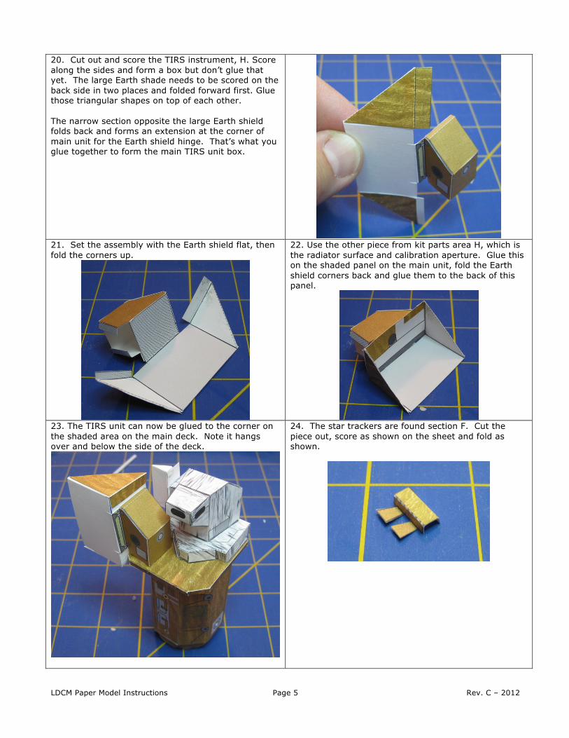
20. Cut out and score the TIRS instrument, H. Score along the sides and form a box but don’t glue that yet. The large Earth shade needs to be scored on the back side in two places and folded forward first. Glue those triangular shapes on top of each other. The narrow section opposite the large Earth shield folds back and forms an extension at the corner of main unit for the Earth shield hinge. That’s what you glue together to form the main TIRS unit box.
21. Set the assembly with the Earth shield flat, then fold the corners up.
22. Use the other piece from kit parts area H, which is the radiator surface and calibration aperture. Glue this on the shaded panel on the main unit, fold the Earth shield corners back and glue them to the back of this panel.
23. The TIRS unit can now be glued to the corner on the shaded area on the main deck. Note it hangs over and below the side of the deck.
24. The star trackers are found section F. Cut the piece out, score as shown on the sheet and fold as shown.

LDCM Paper Model Instructions Page 6 Rev. C – 2012
25. Glue the star trackers to the underside of the main deck in the location indicated by the small shaded rectangle.
26. Cut out the solar array but don’t cut the two halves apart. Simply score along the long edge and fold back on itself and glue that together to make a nice stiff panel. A glue stick works best for this, as white glue may warp the large area.
27. Take a short piece of coffee stirrer (plastic straw) cut to the length noted and cut a slit in the end. Slide the tab at the root of the solar array into the slit (which should go from the root to the edge of the cells), glue, and allow plenty of time to dry. A thick craft glue like Alene’s Tacky Glue works well for this, but regular white glue (Elmers) will do.
28. Once the glue between the straw and solar panel sets up, add another layer of glue to reinforce this joint. You can also use the two L-shaped pieces over this joint for further strength. One goes on each side.
29. When dry, slide the solar array rod into the holes in the bus, being careful to align it through the interior structure you installed in Step 1.
30. You’re done! You now have a really cool LDCM model to show all your friends!
Model design copyright 2012, Michael Mackowski
For more information on building models of real spacecraft, see www.spaceinminiature.com.