land navigation - · pdf filechapter 5 land navigation terrain is another name for a piece of...
TRANSCRIPT
CHAPTER 5
LAND NAVIGATION
Terrain is another name for a piece of ground. Forour purposes, it is a region or territory viewed for itssuitability as a battleground. How you make use of theterrain-its texture, even its color at different times of theday-affects everything you or the enemy do or can do.Both you and the enemy have the terrain of thebattlefield in common. More often than not, victory goesto whoever understands and uses the terrain best.
Usually, the terrain dictates troop movements andformations, positions to be defended, and locations ofweapons. You cannot memorize definite rules to coverevery situation. However, there are certain principlesdiscussed in this chapter that, when applied intelligently,will result in sound solutions or decisions. Knowledgeof these principles is not enough to give you theadvantage. You must know the terrain intimately to useit properly. Other than making a personalreconnaissance of the terrain, you must be thoroughlyfamiliar with the use of commercially prepared maps aswell as maps drawn hastily in the field. You must alsointerpret signs and symbols used on maps, prepare fieldsketches and overlays, and use the lensatic compassproperly.
TERRAIN APPRECIATION
Terrain appreciation is the analysis of an area todetermine the effect that the terrain features have onprobable military operations by either of the opposingforces. Terrain can be viewed with either offensive ordefensive intentions in mind. However, regardless of thetype of mission, each Seabee leader must evaluate theterrain for both offense and defense. Then the Seabeeleader can anticipate the enemy’s analysis of thesituation as well as his own. Information on the terrainmay be acquired through various sources, but a physicalreconnaissance of the area is the most important andreliable method of obtaining accurate information.When a physical reconnaissance is not possible oradditional information is desired, it may be provided byone or more of the following sources:
1.
2.
3.
Aerial reconnaissance and photographs
Maps of the area
Terrain models provided by higher authority
4. Intelligence reports
5. Patrolling
6. Friendly natives, undercover agents, or capturedenemy prisoners
COMPONENTS OF TERRAIN
In military terminology, terrain is simply the groundover which we intend or propose to. fight. To a militaryman, the word terrain is an all-inclusive term, referringnot only to the ground itself, but to all other conditionsthat influence the ability of the combatant to carry outan assigned mission. For the sake of simplicity, terrainhas two major aspects. The first is weather, climate, andseason; the second is topography.
WEATHER CLIMATE, AND SEASON
WEATHER is the day-to-day changes in atmos-pheric conditions. CLIMATE is the average weatherover an extended period of time. SEASONS arecharacterized by particular conditions of weather, suchas summer and winter in the United States or the rainyand dry seasons in Southeast Asia. Of these threeelements, weather is the most important considerationfrom a tactical viewpoint. For long-range planning or inthe absence of weather information, climatological andseasonal data may be used to estimate weatherconditions.
The Elements of Weather
Weather consists of several atmospheric elements,each affecting tactics in its own way. These elements areas follows:
1. TEMPERATURE. The degree of hotness orcoldness in a geographic area.
2. HUMIDITY. The percentage of water vapor inthe air.
3. VISIBILITY. The ability to see bothhorizontally and vertically. It is influenced by fog, haze,heat refraction, clouds, or precipitation.
5-1

4. PRECIPITATION. The depositing of moisture(rain, mist, snow, sleet, hail) from the atmosphere uponthe surface of the earth, expressed in kind and amount.
5. WIND. The movement of air within theatmosphere. It is expressed as strength (velocity) anddirection.
6. PHASES OF THE MOON. Usually, phases ofthe moon are expressed in quarters. The first quarter isbetween the new moon and the full moon; the second,or last quarter, between the full moon and the new moon.The two phases have a direct bearing on night visibilityand the amount of rise and frill of the tides.
The Effect of Weather on Tactics
Weather has a direct effect on the visibility, themovement, and the use and effect of weapons.Horizontal visibility may be materially reduced(resulting in reducing the observation of the enemy orthe effect of your fire on them) by fog, haze, heatrefraction, or precipitation. Vertical visibility may berestricted by fog, precipitation, or a large mass oflow-lying clouds, thus reducing the effectiveness of airsupport or aerial reconnaissance. Ease of movement,both logistical and tactical, on roads or cross-countrymay vary drastically from day to day because ofprecipitation and temperature changes. A heavy rainmay change a passable area into an impassablequagmire; but a severe temperature drop may cause thesame quagmire to frieeze, thus aiding movement.
Weather affects weapons, both in employment andin the effectiveness of the weapon itself. The trajectoryof artillery and mortar rounds is greatly influenced bytemperature and humidity. Extreme cold and hotweather require special treatment and handling ofgasoline engines, thus affecting the use of equipmentand vehicles. The effects of weather are particularlynoticeable in air and naval weapon systems support. Airsupport may be restricted or prevented entirely byclouds, fog, or heavy precipitation. Fog, snow, or heavyrainfall reduce visibility; therefore, naval gunfiresupport cannot be delivered as effectively, and newtargets cannot be rapidly located and engaged.
TOPOGRAPHY
Topography consists of the physical aspects of thesurface of the earth and includes such features as reliefand drainage, vegetation, surface materials, and culturalfeatures.
Relief and Drainage
RELIEF is the term given to the differing areas ofelevation and depression on the surface of the earth.DRAINAGE refers to those areas of surface depressionthat serve as water runoffs or collection points, such asmarshes, swamps, streams, rivers, ponds, and lakes.Knowledge of the general shape of the land is gainedthrough a detailed study of the relief and drainagefeatures. The steepness of slopes; the height and size ofhill masses; the depth, the width, and the length ofdrainage features; and the sizes of valleys and draws aremajor features to consider when studying the terrain ofa given area. These irregularities in the surface of theearth influence tactics by the degree of observation theyprovide the opposing forces, the ease or difficulty ofmovement, and the degree of protection providedagainst enemy fire. Flat ground provides equalobservation for the opposing forces; normally, highground in rolling or mountainous terrain provides forbetter observation.
Any advances made parallel to a series of ridges orto a river or stream are mechanically easier thanmovement perpendicular to them. The steepness of aslope may limit movement; tanks, for instance, cannotclimb slopes greater than 30 degrees.
Flat ground offers little protection against enemyfire, but rolling ground will, particularly againstflat-trajectory weapons.
Vegetation
Vegetation is classified for practical purposes aseither NATURAL or CULTIVATED. Natural plant lifeincludes all types of grasses, bushes, and trees growingwithout the assistance of man; cultivated vegetationincludes all crops and orchards tended by man. Density,height, and types of growth, as well as the diameter oftree trunks, are significant features when you arestudying vegetation.
Although vegetation may restrict vision, it offersconcealment and limited cover. Of course, the thickerthe growth, the harder it is for the forces to move about.
Surface Materials
Surface materials are studied to determine thetrafficability of an area. “Trafficability” is defined as theability of a soil in its normal state to support vehiculartraffic moving cross-country or on unimproved roadsand trails. In general, all types of soil, except very loosesand, afford good trafficability when dry. However, soils
5-2

are seldom completely dry. Water may change soil froma hard, baked clay to slippery, impassable mud within amatter of minutes, especially in tropical areas. Anotheraspect to consider, along with the types and condition ofthe soils, is the slope of the ground, the type ofvegetation, and the roughness of the surface.
Cultural Features
CULTURAL FEATURES include all the works ofman, such as towns, airfields, roads, railroads, andbridges. For military purposes, man-made features areconsidered an integral part of terrain. Cities and townsare frequently the objectives of an attacking force. Fortactical purposes, cultural features may be centers ofresistance as well as physical obstacles in your path.Roads, railroads, and bridges are vulnerable links inlogistics and communication networks.
MILITARY ASPECTS OF TERRAIN
Various combinations of weather and topographygive certain qualities to an area. These qualities, knownas the MILITARY ASPECTS OF TERRAIN, must beclosely evaluated by each unit leader. These qualitiesdetermine to a large degree how he employs his forcesand weapons. You can remember these military aspectsof terrain by using the acronym KOCOA.
K – Key terrain features
O – Observation and fields of fire
C – Cover and concealment
O – Obstacles
A – Avenues of approach
KEY TERRAIN FEATURES
Key terrain is any locality or area that provides thepossessor a marked advantage over the enemy. Usually,the factors that make a feature or an area key terrain aresuperior observation and fields of fire. Obstacles maybe considered key terrain when their possession by oneforce prevents the movement of the opposing force. Insome areas, such as mountains and jungles, wheremovement depends on established roads and paths,routes of communications could be key terrain. A bridgeover an unfoldable river could be key terrain,particularly when its seizure eliminates the need for anassault crossing. An airfield could be key terrain whenits seizure facilitates the success of local operations orserves as a base to support future operations.
In selecting key terrain, the unit leader is beginningto tie his mission to the ground. Inasmuch as key terrainfeatures offer an advantage to one or both combatants,it is apparent that the defender will strive to retain themwhile the attacker tries to seize them. For this reason,key terrain is often assigned as the objectives ofattacking units; conversely, key terrain aids the defenderin disposing his forces to best maintain his battleposition.
Selection of key terrain features varies according tothe mission. In the attack, the unit leader selects keyterrain features forward of the line of departure. In thedefense, the terrain that must be held to maintain theintegrity of the battle position is designated as keyterrain.
Selection of key terrain also varies at the differentlevels of command. For example, at force level, a largecity may offer a marked advantage as a communicationscenter or as a base for supply and maintenance facilities.At division or regiment level, high ground dominatingthe city may be important for observation and fields offire. At battalion, company, and lower echelons, keyterrain might be hills and valleys within the general highground around the city.
OBSERVATION AND FIELDS OF FIRE
OBSERVATION of the battlefield is essential tobring effective fire on the enemy, to controlmaneuvering of your troops, and to prevent beingsurprised by the enemy. Observation is classified aseither long or short range. Long-range observation isthat which provides observation in excess of theeffective range of small-arms fire (usually over 400meters). Short-range observation covers the immediateforeground and extends to the effective range ofsmall-arms fire. Observation is limited or denied bysuch factors as fog, heavy precipitation, heat refraction,darkness, vegetation, cultural features, and relief.
FIELDS OF FIRE are areas into which yourweapons can be fired effectively. An ideal field of firefor the defense would be gentle sloping ground, fitted tothe trajectory of your weapons, and on which the enemycan be seen with no protection from your fire. Thissituation is rarely encountered. However, you canimprove the natural fields of fire by cutting or burningweeds, grass, and crops; by clearing brush and trees; bydemolishing buildings; and by cutting lanes throughwoods. The commander must exercise caution inordering such work, since obviously constructed fire
5-3

lanes can disclose the location of your positions to anobservant enemy.
Observation and fields of fire are so closely relatedthat they are considered together. They are notsynonymous, but fields of fire are based on observation,since the enemy must be seen to bring effective fire onhim. These aspects are particularly important to thedefender. The primary considerations for choosing adefensive position are maximum observation and longfields of fire.
COVER AND CONCEALMENT
COVER is shelter protection from enemy fire,either natural or artificial. Geographical relief features,drainage areas, cultural features, and other artificialshelters provide cover. Cover from flat trajectory fire isbest exemplified by the concept of reverse slope; that is,when there is a projection of relief, such as a hill,between you and the enemy. Cover must be consideredin relation to the types of fire encountered. For example,a trench offers excellent protection against rifle fire, butonly limited protection against mortar or artillery fire.
CONCEALMENT is protection from observation.Vegetation, cultural features, geographical relieffeatures, drainage areas, weather conditions, anddarkness can provide protection from observation.Frequently, you can obtain concealment by properlyevaluating and using just the terrain. At other times, youmay need artificial means (camouflage) in addition tonatural, available concealment.
Concealment is the reverse concept of observation.Since the defender usually has the opportunity to choosethe ground he wishes to defend, he selects positions thattake maximum advantage of natural cover andconcealment, adding field fortifications and naturalconcealment with camouflage to improve the position.It is important that you judge your own cover andconcealment by looking at it from the point of view ofa potential attacker.
OBSTACLES
Obstacles are obstructions that stop or divert troopmovement. Common natural obstacles of military valueinclude mountains, rivers, streams, lakes, marshes,gullies, steep inclines, and heavily wooded areas.Common artificial obstacles include minefield, cut andfalls, trenches, antitank ditches, roadblocks, barbed wire,blown bridges, and road craters. The proper evaluationof natural obstacles permits the most effective use ofartificial obstacles. Obstacles perpendicular to the
advance route of the enemy generally favor thedefending force. Obstacles parallel to the advance of theenemy may favor the enemy by protecting his flanks,although the obstacles may also limit his lateralmovement. The effectiveness of an obstacle must becarefully examined. An obstacle by itself is rarely anabsolute block to military movement by a determinedenemy. A defender who puts full faith in an obstacle byitself stands the risk of being surprised by enemymovement over or through that obstacle. Maximumeffectiveness is gained from an obstacle kept underobservation and fire.
AVENUES OF APPROACH
An avenue of approach is a terrain feature orcombination of features that offer a maneuvering unit asuitable route of movement to their objective. Thedesirable characteristics of an avenue of approach arelisted below.
EASE OF MOVEMENT toward the objective
COVER and CONCEALMENT from the fireand observation of the defender
FAVORABLE OBSERVATION and fields of firefor the attacker
Adequate ROOM FOR MANEUVER anddispersal by the attacking unit
You, as a defender, must pay particular attention toall avenues of approach. These approaches into yourSeabee position represent potential weak spots in thedefense, and Seabees must be positioned to block andcover them effectively. As a defender, you must alsoconsider the use of these avenues of approach by yourown forces should you wish to launch a counterattack.
MAPS AND THE COMPASS
In a combat situation, your life may depend uponyour ability to read and use a map and compass. Whenyou are on a night patrol and become separated from therest of the patrol, you must find your way back tofriendly lines by yourself. This could be next toimpossible without using a map that shows theapproximate location of friendly forces. With a map andcompass, you should be able to locate your position andthen follow a route to your destination.
In this phase of our discussion, we discuss militarymaps first. Then, special attention is given to topics thatshould help you to read maps accurately andintelligently. Later, we discuss the use of a lensatic
5-4

Figure 5-1.—Portion of military map.
compass. Finally, we include instruction on ways toorient a map with a lensatic compass.
MAPS
A map is a small-scale, flat-surfaced representationof a part of the surface of the earth. Man-made and
natural features are shown by the use of symbols, lines,colors, and forms. (See fig. 5-1.) Maps show thelocation and distances between ground features, such astowns, populated areas, roads, airfields, streams, andother lines of communication. They also indicatevariations in the landform and the height of naturalfeatures.
5-5

Figure 5-1.—Portion of military map–Continued.
Some of the types of maps you will use areas follows: are measured from a specified vertical datum plane,
l TOPOGRAPHIC MAP. This map portrays usually mean sea level.
terrain and landforms in a measurable form as well as l PLANIMETRIC MAP. This map presents onlythe horizontal positions of the features represented. The the horizontal positions for the features represented. Thevertical positions, or relief, are normally represented by omission of relief in a measurable form distinguishes itcontours. On relief maps, the elevations and contours from a topographic map.
5-6

Figure 5-1.—Portion of military map–Continued.
l PHOTOMAP. This map is a reproduction of anaerial photograph or a photomosaic made from a seriesof aerial photographs. Photomaps show grid lines,marginal data, place names, route numbers, importantelevations, boundaries, approximate scale, andapproximate direction.
l PICTOMAP. A map on which the photographicimagery of a standard photomap has been converted intointerpretable colors and symbols.
Reference Systems
One of the oldest reference systems is based uponthe geographic coordinates-meridians and parallels.MERIDIANS are great circles of north-south ringscrossing the equator at right angles and converging atthe North and South Poles. (See fig. 5-2.) One meridianthat runs through Greenwich, England, is known as theprime meridian. Meridians are used to measureLONGITUDE–the distance of a point east or west of theprime meridian. PARALLELS are great circles of
Figure 5-2.—Reference lines.
5-7

Figure 5-3.—Position location.
east-west rings running parallel to the equator. (See figs.5-2 and 5-3.) Parallels are used to measureLATITUDE–the distance of a point north or south of theequator. Using meridians and parallels, you can locateany point on the surface of the earth.
Geographic coordinates are expressed in angularmeasurement. The earth is divided into 360 degrees;each degree into 60 minutes; and each minute into 60seconds. The degree is symbolized by °; the minute by´;and the second by´´.
Starting with 0° at the equator, the parallels oflatitude are numbered to 90° both north and south. Theextremities are the North Pole at 90° north latitude andthe South Pole at 90° south latitude. Latitude can havethe same numerical value north or south of the equator,so the direction N or S must always be given.
Starting with 0° at the prime meridian, longitude ismeasured both east and west around the world. Lineseast of the prime meridian are numbered from 0° to 180°and are identified as east longitude. Lines west of theprime meridian are numbered 0° to 180° and areidentified as west longitude. The direction E or W mustalways be given to longitude. The line directly oppositethe prime meridian, 180°, may be referred to as eithereast or west longitude.
Grids
Military maps are divided into grids to provide auniform system for referencing and making
Figure 5-4.—Grid system.
measurements. Military grids consist of two sets ofequally spaced parallel, straight lines intersecting atright angles and forming a series of squares. Each gridline is an even interval of the selected measurement unit,such as yards or meters. A portion of a military grid, ormap, is shown in figure 5-1. The dimensions andorientation of different types of grids vary, but allmilitary grids have three things in common:
1. They are all true rectangular grids.
2. They are superimposed; that is, drawn on top ofthe geographic projection.
3. They permit linear and angular measurements.
The regularly spaced lines that make up the grids onany large-scale map are divisions of the 100 000-meterssquare; the lines are spaced at 10 000- or 1000-meterintervals. Each of these lines is labeled at both ends witha number showing its relation to the origin of the zone.For the 1000-meter grid, except for the numbers labelingthe first grid line in each direction from the southwestcorner of the sheet, the last three digits (000) of thenumber are omitted. (See fig. 5-1.) Two digits of thenumbers are printed in large type, and the same twodigits appear at intervals along the grid line on the faceof the map. They are called the PRINCIPAL DIGITSand represent the 10,000 and 1,000 digits of the gridnumber; they are of major importance to the map readerbecause they are numbers he uses most often forreferencing points. The smaller digits complete theCOORDINATES of the grid lines, but they are rarelyused for point designation. On sheets with grid linespacing at 10000 meters, only one principal digit isshown, representing the 10,000 digit of the grid number.
5-8

Figure 5-5.—Grid square, close-up.
The designation of a point is based on the militaryprinciple of “Read RIGHT then UP.” The precisiondesired determines the number of digits to be readbeyond the principal digits. Remember that the termgrid coordinate often indicates both the 100 000-meters-square identification and the desired number ofdigits. In many instances, it is a tactical requirement thatthe 100 000-meters-square identification be included inany point designation. Figure 5-4 shows a section of asimple grid system. Each line is numbered, starting atthe lower left-hand corner, reading to the right and up.Remember, when you read a military map, you shouldalways read from left to right and from bottom to top.Three squares in figure 5-4 have numbers in them toidentify that particular grid square. The letter X has beenplaced in grid square 6937. To locate this point moreprecisely, see figure 5-5. You can see that the sides ofthe grid square have been divided into ten parts. Thiscan be done by eye or with a scale. As shown in thisfigure, the X is located at coordinate 697373. The gridcoordinates are written as one number but always
contain an even number of digits. Examples are 6937and 697373.
Elevation and Relief
A knowledge of map symbols, grids, scale, anddistance provides enough information to identify twopoints. You locate them, measure between them, anddetermine the length of time required to travel betweenthem. But what happens if there is a 300-foot cliffbetween the two points? The map user must alsobecome proficient in recognizing the various landformsand irregularities of the surface of the earth. Then he isable to determine the elevation and differences in theheight of all terrain features.
1. DATUM PLANE. This is a reference fromwhich vertical measurements are taken. The datumplane for most maps is mean, or average, sea level.
2. ELEVATION. This is defined as the height(vertical distance) of an object above or below a datumplane.
5-9

3. RELIEF. Relief is the representation of the shapeand height of landforms and the characterization of thesurface of the earth.
The elevation of points and the relief of an areaaffect the movement and deployment of units bylimiting the route of travel, their speed of movement,and the ease or difficulty of attacking or defending anarea. Also relief affects observation, fields of fire,cover, concealment, and the selection of key terrainfeatures.
Contour Lines
There are several ways of indicating elevation andrelief on maps. The most common way is by contourlines. A CONTOUR LINE is a line representing animaginary line on the ground along which all points areat the same elevation.
Contour lines indicate a vertical distance aboveor below a datum plane. Starting at sea level,normally the zero contour, each contour linerepresents an elevation above sea level. Thevertical distance between adjacent contour lines isknown as the CONTOUR INTERVAL. The amountof the contour interval is given in the marginalinformation. On most maps, the contour lines areprinted in brown. Starting at zero elevation, everyfifth contour line is drawn with a heavier line.These are known as INDEX CONTOURS.Someplace along each index contour, the line isbroken and its elevation is given. The contour linesfalling between index contours are calledINTERMEDIATE CONTOURS. They are drawnwith a finer line than the index contours and,usually, do not have their elevations given.
Using the contour lines on a map, you maydetermine the elevation of any point as follows:
1. Find the contour interval of the map from themarginal information, and note both the amount and theunit of measure.
2. Find the numbered contour line (or other givenelevation) nearest the point for which the elevation isbeing sought.
3. Determine the direction of slope from thenumbered contour line to the desired point.
4. Count the number of contour lines that must becrossed to go from the numbered line to the desired pointand note the direction-up or down. The number of lines
Figure 5-6.—Estimating elevations between contour lines.
Figure 5-7.—Uniform, gentle slope.
crossed multiplied by the contour interval is the distanceabove or below the starting value.
When the desired point is on a contour line, itselevation is that of the contour.
For a point between contours, most military needsare satisfied by estimating the elevation to an accuracyof one half of the contour interval. All points less thanone fourth of the distance between the lines areconsidered to be at an elevation of one half of the contourinterval above the lower line (fig. 5-6).
To estimate the elevation of the top of an unmarkedhill, add half of the contour interval to the elevation ofthe highest contour line around the hill.
5-10

Figure 5-8.—Uniform, steep slope.
To estimate the elevation of the bottom of adepression, subtract half of the contour interval from thevalue of the lowest contour around the depression.
On some maps, the index and intermediate contourlines do not show the elevation and relief in as muchdetail as may be needed; then SUPPLEMENTARYCONTOURS may be used. These contour lines aredashed brown lines, usually at one half of the contourinterval for the map. A note in the marginal informationindicates the interval used. They are used exactly likesolid contour lines.
On some maps, the contour lines may not meet thestandards of accuracy but are sufficiently accurate inboth value and interval to be shown as contours ratherthan as form lines. On maps of this type, the contoursare considered as approximate and are shown with adashed symbol; elevation values are given at intervalsalong the heavier (index contour) dashed lines. The
5-11
Figure 5-9.—Concave slope.
contour note in the map margin identifies them asapproximate contours.
In addition to the contour lines, bench marks andspot elevations are used to indicate points of knownelevation on the map. BENCH MARKS, the moreaccurate of the two, are symbolized by a black X, forexample, XBM 124. The elevation value shown in blackrefers to the center of the X. SPOT ELEVATIONS,shown in brown, generally are located at road junctions,on hilltops, and other prominent landforms. The symbol‘PAP designates an accurate horizontal control point.When a bench mark and a horizontal control point arelocated at the same point, the symbol BMAPAPAP isused.
The spacing of the contour lines indicates the natureof the slope. Contour lines evenly spaced and wide apartindicate a uniform, gentle slope (fig. 5-7). Contour linesevenly spaced and close together indicate a uniform,steep slope. The closer the contour lines are to eachother, the steeper the slope (fig. 5-8).
Contour lines closely spaced at the top and widelyspaced at the bottom indicate a concave slope (fig. 5-9).Considering relief only, an observer at the top of aconcave slope can observe the entire slope and the

Figure 5-10.—Convex slope.
Figure 5-11.—Hill.
Figure 5-12.—(a) Valley; (b) Draw.
terrain at the bottom. However, a unit attacking upa concave slope would have no cover or conceal-ment from observers or weapons at or near the top;also, farther up the slope, the climb would be moredifficult.
Contour lines widely spaced at the top and closelyspaced at the bottom indicate a convex slope (fig. 5-10).An observer at the top of a convex slope would have noobservation of most of the slope or of the terrain at thebottom. But a unit attacking up a concave slope wouldhave a much greater degree of cover and concealmentthan on a concave slope; also, the climb farther up theslope would be easier.
In order to show the relationship of land formationsto each other and how they would be symbolized on a
5-12

Figure 5-13.—(a) Ridge; (b) Spur.
contour map, stylized panoramic sketches of themajor relief formations are drawn. Then a contourmap of each sketch is developed. Each of thefigures that follow shows a sketch and a map witha different relief feature and its characteristiccontour pattern.
1. HILL. This is a point or small area of highground (fig. 5-11). When you are located on a hilltop,the ground slopes down in all directions.
2. VALLEY. A valley is a course of a stream thathas at least a limited extent of reasonably level groundbordered on the sides by higher ground. (See fig. 5-12,views A and B, top and bottom.) The valley generallyhas maneuvering room within its confines. Contoursindicating a valley are U-shaped and tend to parallela major stream before crossing it. The more gradualthe fall of a stream, the farther each contour parallelsit. The curve of the contour crossing always pointsupstream.
3. DRAW. A draw is a less developed course of astream in which there is essentially no level groundand, therefore, little or no maneuvering room withinits confines. (See fig. 5-12, views A and B, top and
Figure 5-14.—Saddle.
bottom.) The ground slopes upward on each side andtoward the head of the draw. Draws occurfrequently along the sides of ridges at right anglesto the valleys between them. Contours indicating adraw are V-shaped, with the point of the V towardthe head of the draw.
4. RIDGE. Normally, a ridge is a line of highground with minor variations along its crest. (See fig.5-13, views A and B, top and bottom.) The ridge isnot simply a line of hills; all points of the ridge crestare appreciable y higher than the ground on both sidesof the ridge.
5. SPUR. A spur is a short, continuously slopingline of higher ground normally jutting out from theside of a ridge. (See fig. 5-13, views A and B, top andbottom.) A spur is often formed by two roughlyparrallel streams cutting draws down the side of aridge.
6. SADDLE. A saddle is a dip or low point alongthe crest of a ridge. A saddle is not necessarily thelower ground between two hilltops; it maybe simplya dip or break along an otherwise level ridge crest (fig.5-14).
5-13
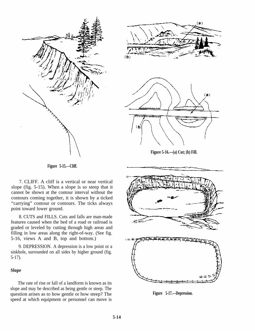
Figure 5-15.—Cliff.
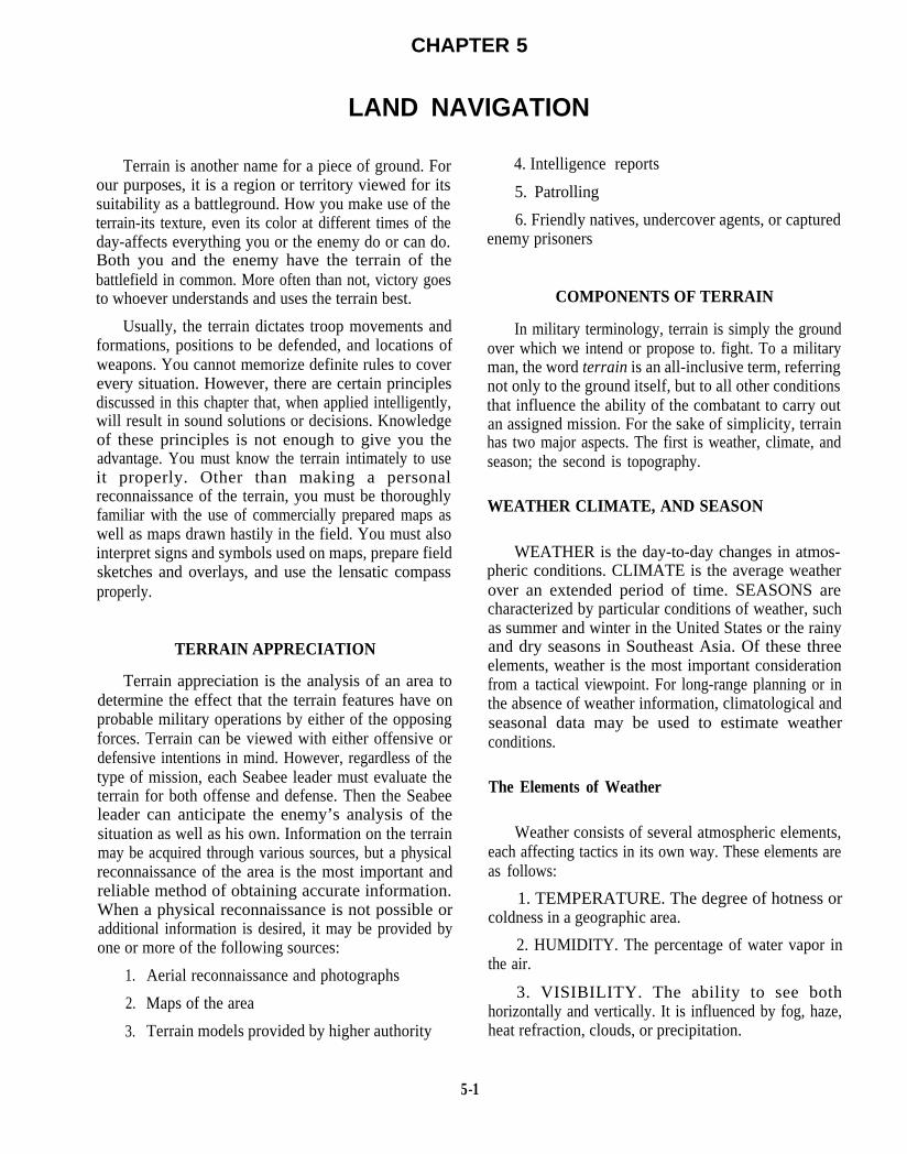
7. CLIFF. A cliff is a vertical or near verticalslope (fig. 5-15). When a slope is so steep that itcannot be shown at the contour interval without thecontours coming together, it is shown by a ticked“carrying” contour or contours. The ticks alwayspoint toward lower ground.
8. CUTS and FILLS. Cuts and falls are man-madefeatures caused when the bed of a road or railroad isgraded or leveled by cutting through high areas andfilling in low areas along the right-of-way. (See fig.5-16, views A and B, top and bottom.)
9. DEPRESSION. A depression is a low point or asinkhole, surrounded on all sides by higher ground (fig.5-17).
Slope
The rate of rise or fall of a landform is known as itsslope and may be described as being gentle or steep. Thequestion arises as to how gentle or how steep? Thespeed at which equipment or personnel can move is
Figure 5-16.—(a) Cut; (b) Fill.
Figure 5-17.—Depression.
5-14
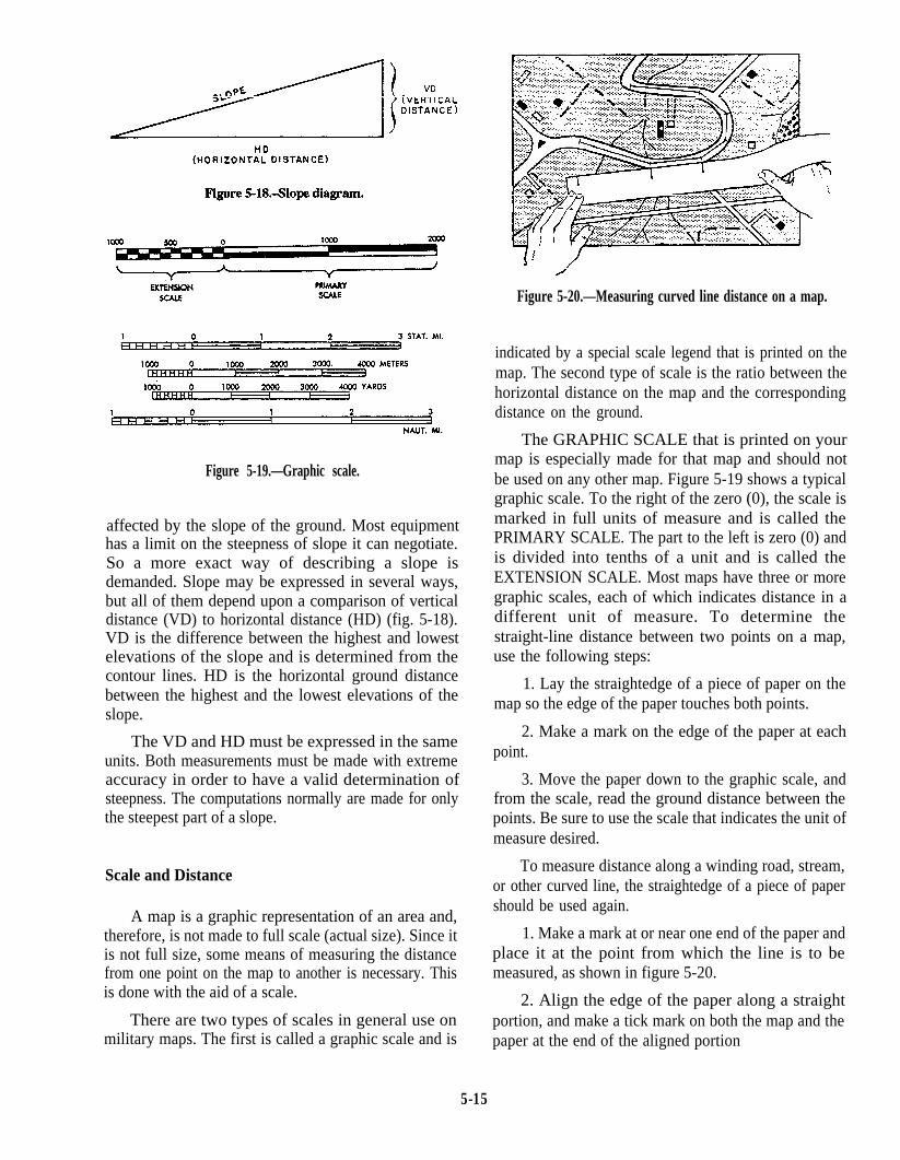
Figure 5-20.—Measuring curved line distance on a map.
Figure 5-19.—Graphic scale.
affected by the slope of the ground. Most equipmenthas a limit on the steepness of slope it can negotiate.So a more exact way of describing a slope isdemanded. Slope may be expressed in several ways,but all of them depend upon a comparison of verticaldistance (VD) to horizontal distance (HD) (fig. 5-18).VD is the difference between the highest and lowestelevations of the slope and is determined from thecontour lines. HD is the horizontal ground distancebetween the highest and the lowest elevations of theslope.
The VD and HD must be expressed in the sameunits. Both measurements must be made with extremeaccuracy in order to have a valid determination ofsteepness. The computations normally are made for onlythe steepest part of a slope.
Scale and Distance
A map is a graphic representation of an area and,therefore, is not made to full scale (actual size). Since itis not full size, some means of measuring the distancefrom one point on the map to another is necessary. Thisis done with the aid of a scale.
There are two types of scales in general use onmilitary maps. The first is called a graphic scale and is
indicated by a special scale legend that is printed on themap. The second type of scale is the ratio between thehorizontal distance on the map and the correspondingdistance on the ground.
The GRAPHIC SCALE that is printed on yourmap is especially made for that map and should notbe used on any other map. Figure 5-19 shows a typicalgraphic scale. To the right of the zero (0), the scale ismarked in full units of measure and is called thePRIMARY SCALE. The part to the left is zero (0) andis divided into tenths of a unit and is called theEXTENSION SCALE. Most maps have three or moregraphic scales, each of which indicates distance in adifferent unit of measure. To determine thestraight-line distance between two points on a map,use the following steps:
1. Lay the straightedge of a piece of paper on themap so the edge of the paper touches both points.
2. Make a mark on the edge of the paper at eachpoint.
3. Move the paper down to the graphic scale, andfrom the scale, read the ground distance between thepoints. Be sure to use the scale that indicates the unit ofmeasure desired.
To measure distance along a winding road, stream,or other curved line, the straightedge of a piece of papershould be used again.
1. Make a mark at or near one end of the paper andplace it at the point from which the line is to bemeasured, as shown in figure 5-20.
2. Align the edge of the paper along a straightportion, and make a tick mark on both the map and thepaper at the end of the aligned portion
5-15

3. Keeping both tick marks together, place thepoint of the pencil on the tick mark of the paper to holdit in place. Pivot the paper until another straight portionis aligned and make another mark on both map andpaper.
4. Continue in this manner until the measurementis complete. Then place the paper on the graphic scaleand read the ground distance.
The RATIO-TYPE SCALE is simply a comparisonbetween a given distance measured on the map and onthe ground. It is independent of any unit of measure.A scale of 1/25,000 means that one unit of measure onthe map is equal to 25,000 of the same units ofmeasure on the ground. The ground distance betweentwo points may be determined by measuring betweenthe points on the map and multiplying the mapmeasurement by the scale. For example, the distancebetween two bridges on a certain map is 15 inches.The scale of the map is 1:50,000. Therefore, the actualdistance on the ground is found by multiplying 15inches by 50,000 (15 times 50,000 equals 750,000inches). If this is to mean anything to you, change itto units that can be easily pictured in your mind. Theseunits might be feet, yards, meters, kilometers, ormiles. To change the 750,000 inches to feet, you needto divide by 12 (the number of inches in a foot); hence750,000 divided by 12 equals 62,500 feet. To changethe 62,500 feet to miles, divide again by 5,280 (thenumber of feet per mile); thus 62,500 divided by 5,280equals 11.8 miles.
By using either of the methods described above, youcan determine the distance between any two points.
Direction
Directions are expressed in everyday life as right,left, straight ahead, and so forth. But the question arises,To the right of what? Military personnel require amethod of expressing a direction that is accurate,adaptable for use in any area of the world, and has acommon unit of measure.
Directions are expressed as units of angularmeasure, and there are several systems used.
1. The most commonly used unit of angularmeasure is the degree with its subdivisions of minutesand seconds.
2. Another unit, less frequently used, is the mil(abbreviated m). For the U.S. military Purposes, acomplete circle is divided into 6,400 mils. The mil is
Figure 5-21.—True, magnetic, and grid azimuths.
commonly used in artillery, tank, and mortar gunnery. Itis convenient for many practical uses because it isapproximately one unit of length at a distance (range) ofone thousand units.
Base Line
In order to measure anything, there must always bea starting point, or zero measurement. To express adirection as a unit of angular measure, there must be astarting point, or zero measure, and a point of reference.These two points designate the base, or reference, line.There are three base lines–true north, magnetic north,and grid north. Those most commonly used aremagnetic and grid; the magnetic when working with acompass, and the grid when working with a militarymap.
TRUE NORTH. This is a line from any position onthe surface of the earth to the North Pole. All lines oflongitude are true north lines. True north is usuallysymbolized by a star (fig. 5-21).
MAGNETIC NORTH. The direction to themagnetic North Pole is indicated by the north-seekingneedle of a magnetic instrument. Magnetic north isusually symbolized by a half arrowhead (fig. 5-21).
GRID NORTH. This is the north established by thevertical grid lines on the map. Grid north may besymbolized by the letters GN (fig. 5-21).
Topographic Map Symbols
The purpose of a topographic map is to permit youto visualize an area of the surface of the earth with
5-16

Figure 5-22.—Topographic symbols.
pertinent features properly positioned. Ideally, allfeatures within an area would appear on the map in theirtrue proportion, position, and shape. However, this is notpractical. Many of the features would be-unimportantand others could not be recognized because of theirreduction in size. Therefore, the map maker has beenforced to use symbols to represent these features. Thesesymbols resemble, as closely as possible, the actualfeatures themselves. (See fig. 5-22.)
Topographic symbols are usually printed in anumber of standardized colors. This is done so thefeatures on the map are easier to identify and to givethem a more natural appearance and contrast.
Black–the majority of cultural or man-madefeatures
Blue–water features, such as lakes, rivers, andswamps
Green–vegetation, such as woods, orchards, orvineyards
Brown–all relief features, such as contours
Red–main roads, built up areas, and special features
Others–occasionally used to show specialinformation; generally, explained in the marginal notes
Military Symbols
In addition to topographic symbols used to representnatural and man-made features of the earth, the militaryestablishment requires some method for showing theidentity, strength, locations, and movements of itstroops, activities, and installations. The symbols used torepresent these features are known as military symbols.As these features are constantly changing and moving,they are not normally printed on the maps. They appearon special maps and overlays and are handled by
5-17

Figure 5-23.—Typica1 military symbols.
following proper security precautions. Figure 5-23shows many of these symbols.
Care of Maps
One of the first precautions in caring for maps isfolding the map properly. Figures 5-24 and 5-25 showways of folding maps to make them small enough to becarried easily and still be available for use withouthaving to unfold them entirely.
Your maps may have to last a long time, so protectthem as best you can. Whenever possible, carry a mapin a waterproof packet, in a pocket, under an outergarment, or other place where it is handy but stillprotected.
In marking a map, use light lines that maybe erasedeasily without smearing, smudging, or leaving marksthat may later tend to confuse someone. If you must trimthe margins of a map for any reason, be careful to copyany marginal information that may be needed later, such
Figure 5-24.—Two methods of folding a map.
5-18

Figure 5-25.—How to slit and fold.
as grid and magnetic declination data or overlappinggrid values and ticks.
LENSATIC COMPASS
The lensatic compass is the most commonly usedand simplest instrument for measuring directions andangles in the field. Two varieties of magneticcompasses are standard for military use today: thelensatic compass (fig. 5-26) and the artillery (M2)compass. Since the M2 is a special-purpose compass,it is not discussed in this chapter.
In order to use a map effectively in the field forpurposes of identification, location, or reporting, youmust orient, or align, the map with the ground. A mapis oriented when, in a horizontal position, its northpoints to the north and all map lines are parallel totheir corresponding lines on the ground. A map useris oriented when he knows his position on theoriented map.
A fast and accurate way to orient a map is with alensatic compass. When a compass rose (picture of acompass card) appears on the map, place the map ona flat surface and draw the magnetic north line. Openthe compass and place it over the magnetic north lineso the sight points toward the top of the map and isdirectly over the magnetic north line that you havedrawn. Turn the map, taking care not to move thecompass from its position over the north line until thenorth arrow of the compass is aligned under the indexline of the compass. The map is now oriented. Formaps that do not have a compass rose, align thecompass sights over a north-south grid line. Thenrotate the map and compass together until the northarrow of the compass points in the same direction andamount from the grid line, shown in the declinationdiagram.
To orient a map when a compass is not availablerequires a careful examination of the map and theground features of the area to find linear features thatare common to both the map and the ground. Linear
Figure 5-26.—Lensatic compass.
5-19

Figure 5-27.—A method of holding the compass. Figure 5-28.—A method of determining the azimuth of a visibleobject.
features are those that have length. Good examples areroads, railroads, fence lines, power lines, and so forth.By aligning the features on the map with the features onthe ground, you can orient the map.
The lensatic compass must always be held level andfirm when you are sighting on an objective and readingan azimuth (a horizontal angle measured in a clockwisereamer from a north base line). There are severaltechniques for holding the compass and sighting, but wewill discuss only two methods.
To sight an objective and read an azimuth with thefirst method, use the following steps:
1. Open the cover of the compass so it forms a rightangle with the compass. Move the eyepiece so thecompass dial is visible through the lens, as shown infigure 5-27.
2. Align the slot in the eyepiece with the hairlinesighting wire in the cover and with the target.
3. Read the azimuth by glancing down at the dialthrough the lens.
This technique provides a reading precise enough touse for “Intersection” and “Resection” (discussed laterin this chapter).
The second method has an advantage because itkeeps the compass lower and farther away from the steel
helmet of the user; but it is less precise than the methodjust described.
To learn the second method, study the followingsteps:
1. Open the cover until it forms a straightedge withthe compass base, as shown in figure 5-26.
2. Pull the eyepiece as far to the rear as possible,perpendicular to the compass base.
3. Place your thumb through the thumb loop,forming a steady base with your third and fourth fingers,and extend your index finger along the side of thecompass.
4. Extend the other index finger along theremaining side of the compass and place the remainingfingers around the fingers of the other hand.
5. Pull your elbows firmly into your sides. Thisplaces the compass between your chin and your belt.
6. To take an azimuth reading, simply turn yourentire body toward the object, pointing the compasscover directly at the object. (See fig. 5-28.)
7. Then just look down and read the azimuth frombeneath the fixed, black index line.
For night use, special features of the compass arethe luminous markings and the 3° bezel serration and
5-20

clicking device. Turning the bezel ring to the left causesan increase in azimuth, while turning it to the rightcauses a decrease. The bezel has a stop and spring thatallows clockwise and counterclockwise turns at 3°intervals per click and holds the bezel ring in any desiredposition. One method for determining compassdirections at night is as follows:
1. Rotate the bezel until the luminous line is overthe black index line.
2. Hold the compass with the left hand andcontinue to rotate the bezel ring with the right hand in acounterclockwise direction for the number of clicksrequired. The number of clicks is determined bydividing the value of the required azimuth by 3. Forexample, for an azimuth of 51°, the bezel ring is rotated17 clicks counterclockwise.
3. Turn the compass until the north arrow isdirectly under the luminous line on the bezel.
4. Hold the compass open and level in the palm ofthe left hand with the thumb along the flat side of thecompass. In this manner, the compass can be heldconsistently in the same position. Position the compassapproximately halfway between the chin and the belt,pointing directly ahead of yourself. A little practice indaylight should make you proficient in pointing thecompass the same way every time. Looking directlydown into the compass, turn your body until the northarrow is under the luminous line. Then move forward inthe direction of the front cover luminous sighting dots(fig. 5-26).
Certain precautions about the care and use of alensatic compass are important because they assure,within reason, that a compass works when and whereyou need it.
1. Handle the compass with care. The dial is set atsuch a delicate balance that a shock could damage thecompass.
2. Close and return the compass to its specialcontainer when it is not in use. In this way, it is not onlyprotected from possible damage but is readily availablefor use when needed.
3. When the compass is to be used in darkness, aninitial azimuth should be set, whenever possible, whilelight is still available. With this initial azimuth as a base,you can read any other azimuth that is a multiple of 3°by using the clicking feature of the bezel.
4. Compass readings should NEVER be taken nearvisible masses of iron or electrical circuits. The
following are suggested as approximate safe distancesto ensure proper functioning of the compass:
High tension power lines . . . . . . . . 55 yards
Field gun, truck, or tank . . . . . . . . 18 yards
Telegraph and telephone wires andbarbed wire . . . . . . . . . . . . . . . 10 yards
Machine gun . . . . . . . . . . . . . . 2 yards
Helmet or rifle . . . . . . . . . . . . . 0.5 yards
Nonmagnetic metals and alloys do not affectcompass readings.
5. Practice by using the compass at regularintervals. This is to help you become competent in itsuse during an emergency.
Azimuth and Back Azimuth
The most common military method of expressing adirection is by using azimuths. As stated before, an“azimuth” is defined as a horizontal angle, measured ina clockwise reamer from a north base line. When theazimuth between two points on a map is desired, thepoints are joined by a straight line. Then a protractor isused to measure the angle between grid north and thedrawn line. This measured angle is the grid azimuth ofthe drawn line (fig. 5-29). When using an azimuth, youimagine the point from which the azimuth originates as
Figure 5-29.—Azimuth angle.
5-21

Figure 5-30.—Origin of azimuth circle.
the back azimuth is the forward azimuth minus 180°.For example, if the forward azimuth of a line is 112°(fig. 5-31), the back azimuth is as follows:
Figure 5-31.—Azimuth and back azimuth.
the center of the azimuth circle (fig. 5-30). Azimuthstake their name from the base line from which they havebeen measured; true azimuths from true north, magneticazimuths from magnetic north, and grid azimuths fromgrid north (fig. 5-21). Therefore, any one given directioncan be expressed in three different ways: a grid azimuth,when measured on a military map; a magnetic azimuth,when measured by a compass; or a true azimuth, whenmeasured from a meridian of longitude.
The BACK AZIMUTH of a line is its forwardazimuth plus 180°; or if this sum is greater than 360°,
Figure 5-32.—Detour around enemy positions or obstacles.
112° + 180° = 292°
When the forward azimuth of a line is 310°, the backazimuth is as follows:
310° - 180° = 130°
Figure 5-32 shows an example of how to bypassenemy positions or obstacles by detouring around them.This allows you to stay oriented by moving at rightangles for specified distances. For example, if you aremoving on an azimuth of 360° and wish to bypass anobstacle or position, you change direction to 90° andtravel for 100 yards; change direction back to 360° andtravel for 100 yards; change direction to 270° and travelfor 100 yards; then change direction to 360°; and youare back on your original azimuth
Bypassing an unexpected obstacle at night is a fairlysimple matter. To make a 90° turn to the right, hold thecompass as described earlier in the method for night use;turn until the center of the luminous letter E is under theluminous line (do NOT change the setting of the
5-22

Figure 5-33.—Types of protractors.
luminous line). To make a 90° turn to the left, turn untilthe center of the luminous letter W is under the luminousline. The compass setting (bezel ring) does not requirechanging, and you can be sure of accurate 90° turns. Forexample, you decide to detour to the right. You turn untilE is under the luminous line and move ahead in thatdirection until you have outflanked the obstacle. Youthen turn until the north arrow is under the luminous lineand move parallel to your original course until you havebypassed the obstacle. You then turn again until the W
is under the luminous line and move back the samedistance you originally moved out. Finally, you turnuntil the north arrow is under the luminous line and goahead on your original course. This method worksregardless of what your initial azimuth may be.
Protractor
Protractors come in several forms–full circle, halfcircle, square, and rectangle (fig. 5-33). All of them
5-23

Figure 5-34.—Measuring an azimuth on a map.
divide a circle into units of angular measure; andregardless of their shape, they consist of a scale aroundthe outer edge and an index mark The INDEX MARKis the center of the protractor circle from which all thedirection lines radiate.
To determine the grid azimuth of a line from onepoint to another on the map (from A to B or C to D), referto figure 5-34 as you study the following:
1. Draw a line connecting the two points.
2. Place the index of the protractor at the pointwhere the line crosses a vertical (north-south) grid line.
3. Keeping the index at this point, align the0°-180° line of the protractor on the vertical grid line.
4. Read the value of the angle from the scale; thisis the grid azimuth of the point.
To plot a direction line from a known point on a map,refer to figure 5-35 as you study the following:
1. Convert, if necessary, the direction toazimuth.
2. Construct a north-south grid line through theknown point. Then proceed in the following steps:
l First, approximately align the 0°- 180° line ofthe protractor in a north-south direction through theknown point.
5-24

Figure 5-35.—Plotting an azimuth on a map.
l Second, holding the 0° - 180° line of the Intersectionprotractor on the known point, slide the protractor in thenorth-south direction. Slide it until the horizontal line of Locating an unknown point by successivelythe protractor (connecting the protractor index and the90° tick mark) is aligned on an east-west grid line.
l Draw a line connecting 0°, the known point, and180°.
l Holding the 0° - 180° line coincident with thisline, slide the protractor index to the known point.
l Make a mark on the map at the required angle.
l Draw a line from the known point through the markmade on the map. This is the GRID DIRECTiON line.
occupying at least two, but preferably three, knownpositions and sighting on the unknown point is calledintersection. It is used to locate features that are notdefined on the map or which are not readilyidentifiable. The two methods of intersection are themap and compass method and the straightedgemethod.
MAP AND COMPASS METHOD.— Study thefollowing steps to locate an unknown point using the
5-25

Figure 5-36.—Intersection using map and compass.
map and compass method of intersection. (See fig.5-36.)
1. Orient the map using the compass.
2. Locate and mark your position (Point A) on themap.
3. Measure the magnetic azimuth to the unknownposition; convert it to grid azimuth.
4. Draw a line on the map from your position onthis grid azimuth.
5. Move to a second known position (Point B) fromwhich the unknown point is visible. Locate this positionon the map and again orient the map using the compass.
6. Repeat Steps 3 and 4 above.
7. As a check on accuracy, move to a third position(Point C) and repeat Steps 1 through 4 above.
8. The point where the lines cross is the location ofthe unknown position. Using three lines, you sometimesform a triangle instead of an intersection. This is calledthe TRIANGLE OF ERROR. If the triangle is large,
5-26

Figure 5-37.—Intersection without compass.
recheck your work to find the error. Do not assume thatthe position is at the center of the triangle.
STRAIGHTEDGE METHOD (WHEN NOCOMPASS IS AVAILABLE).— Study the followingsteps to locate an unknown point using the straightedgemethod of intersection. (See fig. 5-37.)
1. Orient the map on a flat surface by the inspectionmethod.
2. Locate and mark your position on the map.
3. Lay a straightedge on the map and place one endat the position of the user (Point A) as a pivot point. Then
rotate the straightedge until the unknown point is sightedalong the edge.
4. Draw a line along the straightedge.
5. Repeat the above procedures at Point B, and fora check on accuracy, at a third position.
6. The intersection of the lines is the location ofunknown Point C.
Resection
Locating the unknown position of the user bysighting on two or three known features is called
5-27

Figure 5-38.—Resection.
resection (fig. 5-38). Resection can be done with orwithout a compass.
MAP AND COMPASS METHOD.— Study thefollowing steps to locate the unknown position of theuser by the map and compass method:
1. Orient the map using the compass.
2. Locate two or three known positions on theground and mark them on the map.
3. Measure the magnetic azimuth to a knownposition; convert it to grid azimuth.
4. Change the grid azimuth to a back azimuth anddraw a line on the map from the known position backtoward your unknown position.
5. Repeat Steps 3 and 4 above for a second knownposition.
6. For a check on your accuracy, repeat Steps 3 and4 above for a third known position.
7. The intersection of the lines is your location.Using three lines, a triangle of error maybe formed. Ifthe triangle is large, recheck your work.
5-28
STRAIGHTEDGE METHOD.— Study thefollowing steps to locate the unknown position of theuser by the straightedge method:
1. Orient the map on a flat surface by the inspectionmethod.
2. Locate two or three known positions on theground and mark them on the map.
3. Lay a straightedge on the map with the centerof the straightedge at a known position as a pivotpoint. Rotate the straightedge until the known positionon the map is aligned with the known position on theground.
4. Draw a line along the straightedge away fromthe known position on the ground toward yourposition.
5. Repeat Step 3 above using a second knownposition; and as a check on your accuracy, repeat Step 3above, using a third known position.
6. The intersection of the lines is your location.

SKETCHES AND OVERLAYS TOPOGRAPHIC SKETCHES
You are not expected to be a draftsman. But youshould be able, if necessary, to make rough drawings ofmaps, field sketches, and overlays. The instructionpresented in this chapter about maps is designed to assistyou in making rough drawings of them. The informationbelow will be useful in preparing a rough drawing of afield sketch or map overlay.
The two types of sketches are panoramic andtopographic.
PANORAMIC SKETCHES
A panoramic sketch is a picture of the ground orterrain. It shows the height and view from your point ofobservation. A panoramic sketch prepared by one scoutmay assist another scout in finding himself for a brieftime in the same location.
To make a panoramic sketch, use the followingguidance:
1. First, determine the information you desire toconvey.
2. Next, draw in the landscape lines that are moreor less horizontal.
3. Show the main points of the area on the sketch.Do not put in any unimportant details that might only beconfusing, and do not show the foreground. Be sure youshow the location of the information you are conveying.
4. Place any explanatory notes above the sketchwith arrows pointing to the features explained.
5. The most prominent point in the sketch shouldbe used as a reference point. After selecting this point,indicate the azimuth reading used to locate it.
6. Place a title on the sketch, show where it wasprepared, indicate the date and the time it was made;then sign it.
A topographic sketch is prepared so the personreceiving it can plot on a map your scouting position orthe information you wish to convey. To prepare atopographic sketch, you need a map similar to one yourcommander has in his possession.
1. Read the azimuth from your position to theposition of an object you can easily see and describe.
2. Estimate the distance, using the most accuratemeans available.
3. Draw the azimuth line from you to the object.Then mark the azimuth above this line and the distancebelow this line.
4. At the proper end of the line, indicate the object.At the other end of the line, indicate your own position.
5. Find the azimuth and the distance to some otherpoint on the map or to the position of the command post.
6. Draw this line on the sketch. Then indicate theazimuth, the distance, and the object to which it isdrawn.
7. Finally, sign the sketch.
MAP OVERLAYS
A map overlay is generally used to send backreconnaissance information. The overlay is made byplacing apiece of transparent paper on a map, markingthe location, and numbering the corners of the gridsquares. At least two corners should be marked orcrossed. These crosses are called REGISTER MARKSand are used to orient the overlay on a map later on. Afterthe register marks have been made, you only need towrite the information that is to be sent back to thecommand post. When the overlay is receive&it will beplaced on a similar map and oriented by its registermarks and the information you recorded.
5-29
