laker: learning from past actions to guide future behaviors in ad hoc routing
TRANSCRIPT

WIRELESS COMMUNICATIONS AND MOBILE COMPUTINGWirel. Commun. Mob. Comput. 2007; 7:495–511Published online 24 July 2006 in Wiley InterScience (www.interscience.wiley.com). DOI: 10.1002/wcm.368
LAKER: learning from past actions toguide future behaviors in ad hoc routing
Jian Li*,y and Prasant Mohapatra
Department of Computer Science, University of California, Davis, CA 95616, U.S.A.
Summary
In this paper, we present a location aided knowledge extraction routing (LAKER) protocol for mobile ad hoc
networks (MANETs). The novelty of LAKER is that it learns from past actions to guide future behaviors. In
particular, LAKER can gradually discover current topological characteristics of the network, such as population
density distribution, residual battery map, and traffic load status. This knowledge can be organized in the form of a
set of guiding routes, each of which consists of a chain of guiding positions between a pair of source and
destination locations. The guiding route information is learned by individual nodes during route discovery phase,
and it can be used to guide future route discovery processes in a more efficient manner. LAKER is especially
suitable for mobility models where nodes are not uniformly distributed. LAKER can exploit topological
characteristics in these models and limit the search space in route discovery processes in a more refined
granularity than location aided routing (LAR) protocol. Simulation results show that LAKER outperforms LAR
and DSR in term of routing overhead, saving up to 30–45% broadcast routing messages compared to LAR
approach. Copyright # 2006 John Wiley & Sons, Ltd.
KEY WORDS: guiding route and forwarding route; knowledge discovery; knowledge guided routing; LAKER;
mobile ad hoc networks
1. Introduction
Mobile ad hoc network (MANET) is an infrastruc-
tureless network formed by a set of wireless nodes that
are capable of moving around freely. There is no fixed
infrastructure such as base stations. Each mobile node
acts as an end-system as well as a router. Two mobile
nodes within the transmission range of each other can
communicate directly via the ad hoc wireless link. A
multihop route is needed when the destination is
beyond the coverage of the sender. Hence routing is
a key component of MANET performance. A number
of routing protocols have been proposed for MANETs
during the recent years [1,2]. Most of these routing
protocols can be classified into two categories: proac-
tive protocols and reactive (on-demand) protocols. In
proactive approaches, each node will maintain routing
information to all possible destinations irrespective of
its usage. In on-demand approaches, a node performs
route discovery and maintenance only when needed.
*Correspondence to: Jian Li, Department of Computer Science, University of California, Davis, CA 95616, U.S.A.yE-mail: [email protected]
Contract/grant sponsor: National Science Foundation; contract/grant numbers: CCR-0296070, ANI-0296034.
Copyright # 2006 John Wiley & Sons, Ltd.

Due to the nodal mobility and fast changing topology,
on-demand protocols generally outperform purely
proactive protocols.
In wireless network simulations, the mobility
model has a significant impact on the performance
of the protocol under evaluation. The mobility model
dictates how the nodes move in the networks, which
results in network dynamics such as link breakages,
route failures, and changes in nodal density and
topology. All these factors can affect the performance
of the ad hoc routing protocol, in terms of routing
overhead, packet delivery ratio, and end-to-end delay.
A good summary and comparison of various mobility
models can be found in Reference [3].
Among the proposed models, the ‘Random Way-
point’ [18] mobility model is most widely used in
performance evaluation of ad hoc routing protocols.
In this model, initially all the mobile nodes are uni-
formly distributed in the simulation area. When the
simulation starts, each node stays at its initial position
for a specific duration called pausetime, and then
randomly selects a destination within the simulation
area, and starts moving towards this destination with a
stable speed, which is randomly chosen from a pre-
defined range. When the mobile node arrives at the
destination, it will stay there for pausetime seconds,
then chooses another destination and new speed and
continues to move, and so on.
The ‘Random Waypoint’ mobility model does not
capture the mobility and topological characteristics in
the cases where nodes may cluster at some sub-
regions of interest instead of randomly moving
around. For example, there are several events occur-
ring at different places on a large campus, mobile
users roam from one event location to another, paus-
ing for a certain period of time at each location. We
believe this is more realistic than randomly choosing
destination. Another example is that there is an
obstacle region (like a lake) within the simulation
area and the mobile users are restricted from entering
these regions. In order to capture this kind of mobility
patterns, a recent work [4] proposed the ‘Restricted
Random Waypoint’ model. In this modified mobility
model, a mobile node will randomly choose a destina-
tion only from a set of sub-regions, which are sepa-
rated as small parts of the whole simulation area. A
similar mobility model was used in Reference [5].
Some more recent work on ad hoc mobility modeling
can be found in References [6,7].
In this paper, we adopt the ‘Restricted Random
Waypoint’ mobility model, and propose a new routing
approach: location aided knowledge extraction rout-
ing (LAKER) protocol. The design of LAKER is
aimed at taking advantage of topological character-
istics (e.g., distribution of population density) of the
network. During a route discovery process, our ap-
proach attempts to extract knowledge of the node
density distribution in the network, and memorizes
the series of locations along the route where the nodal
density is high. We call the series of ‘important’
locations (not nodes) as a guiding route. The motiva-
tion behind the guiding route is that, in many situa-
tions, even though individual nodes may move fast,
the population density distribution of the network
does not change so rapidly. Take a look at the previous
campus events example: while individual users may
come and go from an event location to another,
relatively fast, the topological distribution of these
populated event spots will stay mostly unchanged
over the time. This observation justifies the possibility
of discovering topological characteristics of the net-
work, which we term as guiding information. Using
the guiding information, we can further narrow the
search space in the route discovery process and, at the
same time, overcome the problem of ‘void’ area in
the network. Simulation results show that LAKER can
save up to 30–45% broadcast control messages com-
pared to the LAR approach, while achieving higher
delivery ratio and similar or better end-to-end delay.
The rest of this paper is organized as follows. In
Section 2, we provide some preliminaries. The
design of LAKER protocol is described in Section 3.
Performance evaluation of LAKER based on simula-
tion is presented in Section 4. Section 5 outlines the
related efforts, followed by the concluding remarks in
Section 6.
2. Preliminaries
In this section, we first introduce the operation of
flooding-based route discovery in ad hoc networks as
well as techniques in reducing flooding overhead
during the process. Our LAKER approach is related
to this line of discussion. We then present some
important assumptions made to facilitate the discus-
sion for the rest of this paper. We will also discuss the
notion of guiding route, which is the cornerstone of
our work in this paper, and the difference between
guiding route and forwarding route.
LAKER inherits the route caching strategy from
DSR. In addition to caching forwarding route as DSR
does, LAKER also attempts to cache a new kind of
information about the network topology—guiding
496 J. LI AND P. MOHAPATRA
Copyright # 2006 John Wiley & Sons, Ltd. Wirel. Commun. Mob. Comput. 2007; 7:495–511

route. By caching the guiding routes in LAKER,
the topological characteristics of the network are
exploited, hence the mobility model used in study
will have a greater impact on our algorithm.
2.1. Flooding Based Route Discovery
On-demand protocols, such as dynamic source routing
(DSR) [8] and ad hoc on demand distance vector
(AODV) routing [9], often use flooding techniques
to search for a new route. Flooding-based route dis-
covery works as follows. When a node S has some
data to send to node D but has no existing route to the
destination, it will initiate a route discovery process
by broadcasting a route-request packet. An intermedi-
ate node I, upon receiving the route-request packet for
the first time, will rebroadcast the route-request again
if it does not know a route to the destination node D.
Finally, when the route-request packet arrives at a
node (which may be the destination node D itself) that
has a route to node D, a route-reply packet is sent back
to the sender node S.
To reduce the flooding overhead, a variety of
optimizations have been developed. For example,
DSR aggressively utilizes route caching strategy to
reduce the number of route-request messages. As the
route-reply message propagates back to the requester,
all neighboring nodes along the route can listen to the
route information in a promiscuous way and store the
route information in its cache. Later, when a new
route-request message is propagating in the network,
an intermediate node that has a cached route to the
destination can reply to the requester without relaying
the route-request message. So the total routing over-
head can be reduced. The disadvantage of caching
route is that these cached routes may be obsolete by
the time it is used, especially under relatively high
mobility. Our idea is that it will be more desirable to
cache some long-lived properties of the network other
than the to-be-broken routes. In real mobility patterns,
nodal density may not be uniform across the network.
Some parts of the network may have dense clusters of
nodes, while some other parts may have sparsely
distributed nodes. We believe it is helpful to discover
and cache this kind of nodal distribution information
and use it to guide future route discovery processes.
Another technique to reduce flooding overhead is
using the geographical location to limit the flooding
area. This approach is used in some protocols such as
LAR [10] and DREAM [11]. According to both the
sender and the receiver’s locations, a reduced flooding
sub-region can be defined instead of flooding the
entire network. For example, in LAR the geographical
location information is carried with the route-request
messages. Upon receiving a route-request message, an
intermediate node will determine if it is in the reduced
flooding area. Only those nodes in the limited area
rebroadcast the route-request message, hence the
number of routing messages is reduced. In some
cases, however, this method of defining the flooding
area solely by the source and destination locations is
too coarse in granularity. In some other cases, it may
not be able to overcome the ‘void’ area in the network
and has to resort to flooding the entire network
(discussed later in Subsection 3.1).
Our motivation behind LAKER is to exploit the
topological characteristics in non-uniform network
environments. With the assistance of guiding knowl-
edge, LAKER naturally leads to even more limited
search space and thus more reduced routing overhead,
while being capable of bypassing some ‘void’ area.
2.2. Assumptions
The assumptions we make for our discussion about
LAKER are as follows.
� Each node knows its current location, for example,
by means of global positioning system (GPS) [14].
In cases where the mobile nodes do not have GPS
capabilities, some form of localization technique
can been used to obtain location information of
individual nodes. A lot of GPS-free localization
methods for mobile networks have been proposed
in the literature (e.g., see [15,16]), which is beyond
the scope of this paper.
� Each node keeps track of the number of neighbors it
has. This can be achieved, for example, by means of
periodic beaconing messages on the network layer,
or with assistance from the data link layer.
� Each node has an end-system unique identifier
(EUI).
� There exists a geographical location service (e.g.,
see Reference [17]). When node S has data to send
to node D, node S can obtain node D’s approximate
location by looking up the location service.
2.3. Guiding Route Versus Forwarding Route
The basic idea of LAKER is to distinguish guiding
route from forwarding route. A forwarding route is
a series of node EUIs, which connect a source node to
a destination node hop by hop. A guiding route is a
LAKER 497
Copyright # 2006 John Wiley & Sons, Ltd. Wirel. Commun. Mob. Comput. 2007; 7:495–511
series of ‘important’ locations, which start from one
location (source) and lead to another location (desti-
nation). In particular, we consider node population
distribution in this paper, and the importance of a
location is determined by the number of neighboring
nodes at that place. In this context, a guiding route is a
series of locations along a forwarding route where
there seems to be many nodes clustering together. For
example, S! B! L!M! A! C!W! D is a
forwarding route between nodes S and D. Assume that
nodes B, M, Ware in locations where the node density
is high, whereas nodes L, A, C are in lightly populated
areas. Therefore, a guiding route between S’s location
and D’s location is: (Xs, Ys)! (Xb, Yb)! (Xm, Ym)!(Xw, Yw) ! (Xd, Yd).
The rationale behind this approach is that, although
individual nodes may come and go fast, the structure
of populated areas is not expected to change so
rapidly. So it is possible to discover and cache this
long-lasting guiding information during the route
discovery process. In the next round of route discov-
ery process, this information can be used to guide the
route discovery direction and narrow the search space,
even at a finer granularity than the LAR approach.
3. LAKER Protocol
In this section, we describe our proposal — a LAKER
protocol for MANETs. The guiding routes—which
have the knowledge of the population density distri-
bution of the network—play an important role in
LAKER’s route discovery process. Existing knowl-
edge can be used to guide the flooding, and new
knowledge may be discovered in the course of route
discovery. We will discuss two important functional-
ities of LAKER: knowledge guided route discovery
and location aided knowledge discovery.
3.1. Knowledge Guided Route Discovery
With self-discovered knowledge of current network
status, LAKER can direct route discovery processes
in a more efficient manner. In this subsection, we
describe the new fields we add to LAKER’s routing
messages to accommodate guiding information. We
also present LAKER’s knowledge guided routing
algorithm, and the advantages of using this approach.
3.1.1. Extensions to routing messages
In addition to the functionalities of DSR and LAR,
LAKER needs extensions to the route-request and
route-reply messages to facilitate knowledge discov-
ery and smart routing behaviors. The important fields
in LAKER’s route-request message and their mean-
ings are listed in Table I.
As shown in Table I, the first three items are
standard contents of a DSR route-request message.
As the name indicates, traversed forwarding route
stores a chain of node EUIs that have been traversed
so far. The next two items, source location and
destination location, are introduced in LAR to define
the request zone, which may be chosen as a rectan-
gular shape. The last two items are newly introduced
in our proposal of LAKER. The field guiding route
stores the existing guiding information to direct
current route discovery process. Initially this field
may be empty if the source node does not have
any guiding route to the destination location. As
the route-request message propagates in the network,
intermediate nodes may fill in some guiding informa-
tion if they have. Even if the route-request message
starts with a guiding route, intermediate nodes
can still update the field guiding route if they have
newer information. The field traversed guiding route
stores a chain of ‘important’ positions, that is, the
newly discovered partial guiding information, as the
route-request message propagates in the network.
The route-reply message contains these fields: sour-
ce EUI, destination EUI, discovered forwarding route,
and discovered guiding route. Their meanings are si-
milar to those fields in the route-request message.
3.1.2. Route discovery algorithm
LAKER uses an on-demand request-reply mechanism
in route discovery. When node S needs a route to node
D but cannot find one in its cache, it will initiate a
route discovery process by broadcasting route-request
message into the network.
The LAKER route discovery algorithm is shown
in Algorithm 1. RREQ stands for a route-request
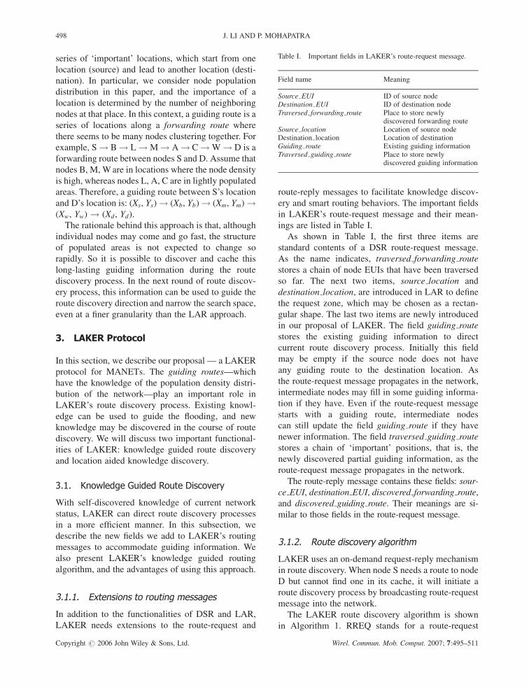
Table I. Important fields in LAKER’s route-request message.
Field name Meaning
Source EUI ID of source nodeDestination EUI ID of destination nodeTraversed forwarding route Place to store newly
discovered forwarding routeSource location Location of source nodeDestination location Location of destinationGuiding route Existing guiding informationTraversed guiding route Place to store newly
discovered guiding information
498 J. LI AND P. MOHAPATRA
Copyright # 2006 John Wiley & Sons, Ltd. Wirel. Commun. Mob. Comput. 2007; 7:495–511
message, and RREP for a route-reply message. Upon
receiving RREQ, intermediate node X first adds its
guide position to the traversed guiding route field in
RREQ if it thinks its location is important (this will be
further discussed in Subsection 3.2). Node X then
decides if it is within the request zone based on the
guiding information carried in RREQ, and processes
RREQ accordingly, that is, rebroadcasts or drops it.
During this process, intermediate nodes can update
the guiding route field in RREQ if they have newer
guiding information towards the destination location.
This algorithm is executed at intermediate nodes,
hop by hop, until the route-request message reaches a
node that has a forwarding route to the destination, or
reaches the destination node itself. One or multiple
route-reply messages will get back to the source node.
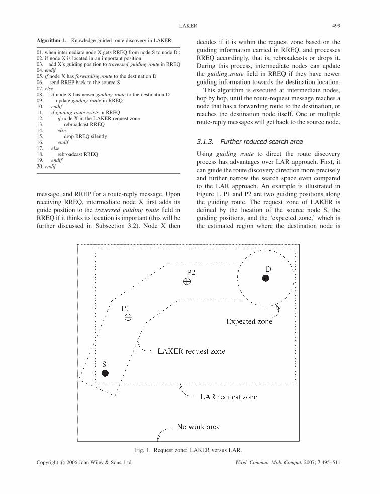
3.1.3. Further reduced search area
Using guiding route to direct the route discovery
process has advantages over LAR approach. First, it
can guide the route discovery direction more precisely
and further narrow the search space even compared
to the LAR approach. An example is illustrated in
Figure 1. P1 and P2 are two guiding positions along
the guiding route. The request zone of LAKER is
defined by the location of the source node S, the
guiding positions, and the ‘expected zone,’ which is
the estimated region where the destination node is
Fig. 1. Request zone: LAKER versus LAR.
Algorithm 1. Knowledge guided route discovery in LAKER.
01. when intermediate node X gets RREQ from node S to node D :02. if node X is located in an important position03. add X’s guiding position to traversed guiding route in RREQ04. endif05. if node X has forwarding route to the destination D06. send RREP back to the source S07. else08. if node X has newer guiding route to the destination D09. update guiding route in RREQ10. endif11. if guiding route exists in RREQ12. if node X in the LAKER request zone13. rebroadcast RREQ14. else15. drop RREQ silently16. endif17. else18. rebroadcast RREQ19. endif20. endif
LAKER 499
Copyright # 2006 John Wiley & Sons, Ltd. Wirel. Commun. Mob. Comput. 2007; 7:495–511
currently located. As discussed earlier, the population
density is not uniformly distributed in the network
area. There are some sub-regions with higher popula-
tion density. In route discovery phase, it is very likely
to find a feasible route by limiting the search space
along this chain of ‘populated spots.’ Only nodes in
this narrow band will participate in the route discov-
ery process. Since the search area is further reduced,
LAKER is expected to incur less routing overhead
than LAR approach.
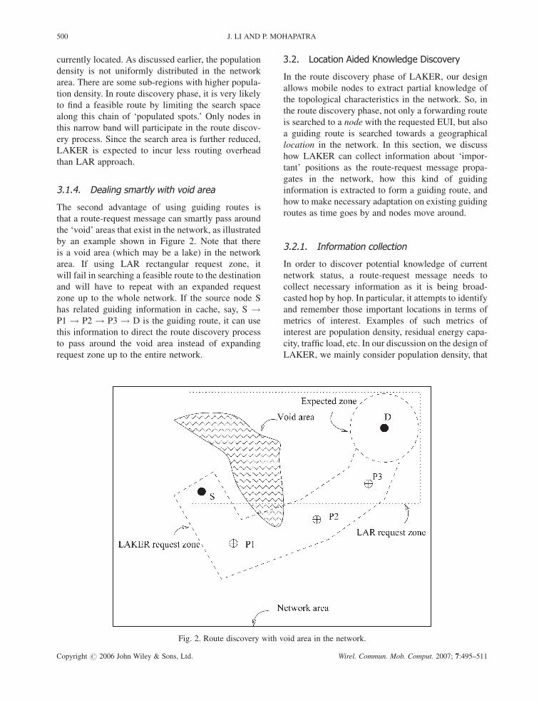
3.1.4. Dealing smartly with void area
The second advantage of using guiding routes is
that a route-request message can smartly pass around
the ‘void’ areas that exist in the network, as illustrated
by an example shown in Figure 2. Note that there
is a void area (which may be a lake) in the network
area. If using LAR rectangular request zone, it
will fail in searching a feasible route to the destination
and will have to repeat with an expanded request
zone up to the whole network. If the source node S
has related guiding information in cache, say, S !P1 ! P2 ! P3 ! D is the guiding route, it can use
this information to direct the route discovery process
to pass around the void area instead of expanding
request zone up to the entire network.
3.2. Location Aided Knowledge Discovery
In the route discovery phase of LAKER, our design
allows mobile nodes to extract partial knowledge of
the topological characteristics in the network. So, in
the route discovery phase, not only a forwarding route
is searched to a node with the requested EUI, but also
a guiding route is searched towards a geographical
location in the network. In this section, we discuss
how LAKER can collect information about ‘impor-
tant’ positions as the route-request message propa-
gates in the network, how this kind of guiding
information is extracted to form a guiding route, and
how to make necessary adaptation on existing guiding
routes as time goes by and nodes move around.
3.2.1. Information collection
In order to discover potential knowledge of current
network status, a route-request message needs to
collect necessary information as it is being broad-
casted hop by hop. In particular, it attempts to identify
and remember those important locations in terms of
metrics of interest. Examples of such metrics of
interest are population density, residual energy capa-
city, traffic load, etc. In our discussion on the design of
LAKER, we mainly consider population density, that
Fig. 2. Route discovery with void area in the network.
500 J. LI AND P. MOHAPATRA
Copyright # 2006 John Wiley & Sons, Ltd. Wirel. Commun. Mob. Comput. 2007; 7:495–511

is, try to remember those places with dense distribu-
tion of mobile nodes.
As described in Algorithm 1, when relaying a route-
request packet, if an intermediate node believes that
its location is of importance, it will calculate its
guiding position, and append this information to the
traversed guiding route field in the route-request
packet. Note that a node’s guiding position is different
from its own geographical location. Instead, it is a
calculated position which indicates a spot where there
are many mobile nodes.
How can a node determine its guiding position?
The procedure is shown in Algorithm 2. First, each
node keeps track of the number of its direct neighbors.
If the number of slow neighbors (i.e., with speed under
S1) exceeds a certain threshold, K1, the node will
consider itself located in an important position in term
of population density. We only consider relatively
slow neighbors because we are interested in stabler
clusters. Second, the node calculates its guiding posi-
tion by obtaining the average of coordinates of all its
slow neighbor nodes. This use of average coordinates
can overcome inaccuracy when an intermediate node
is located at the edge of a populated spot because its
guiding position is the center of its neighbors instead
of its own position. An example for such cases is
illustrated in Figure 3.
3.2.2. Knowledge extraction
When a route-request message finally reaches the
destination node, it contains both forwarding route
and guiding positions information. Based on our
assertion, a guiding route is a chain of locations that
indicates a ‘good’ search direction for route discovery
process. To achieve this design goal, we need to
Fig. 3. An example: how node X gets its ‘accurate’ guiding position.
Algorithm 2. Determination of a node’s guiding position.
01. At intermediate node I, upon relaying a RREQ message:02. ctr = 0; G=fg /* G is initially an empty set*/03. for each neighboring node Ni of node I04. if speed(Ni) < S105. put Ni into G set06. ctr ++07. endif08. if ctr > K1
09. mark this position as ‘‘important’’ in RREQ message10. calculate node I’s guiding position:
11. Guide PosðIÞ:X ¼PjGj
i¼1Xi
jGj /* jGj is the number of nodes in Gset */
12. Guide PosðIÞ:Y ¼PjGj
i¼1Yi
jGj13. endif
LAKER 501
Copyright # 2006 John Wiley & Sons, Ltd. Wirel. Commun. Mob. Comput. 2007; 7:495–511

extract appropriate guiding positions from all those
potential candidates to form a ‘good’ guiding route.
By appropriate, we mean that we do not want two
adjacent guiding positions to be too close or too far
away. If they are too close or too far, the resultant
guiding route will lose its function as an indicator of
search direction. In our simulations, we find that this
parameter is quite application-specific and depends on
factors such as wireless transmission range and net-
work density.
After the destination node extracts forwarding route
and guiding route information from the received
route-request message, it will send a route-reply
message back to the route requester (i.e., the source).
As the route-reply packet propagates back to the
source node, it contains both forwarding route and
guiding route between the source and destination pair.
We assume that each mobile node operates in a
promiscuous mode, so it can snoopz guiding route as
well as forwarding route information from all pass-by
routing packets it eavesdrops.
When the route-reply message gets back to the
source node, it will cache both the guiding route as
well as the forwarding route information. Note that,
before adding newly learned guiding route to its
cache, a node will first decide whether this guiding
route adds new knowledge by comparing it with prior
guiding routes in cache. If it is determined that this
new guiding route is fairly close to one of the existing
guiding routes in cache, the new guiding route will be
discarded. Since cache size is limited, if the cache if
full, a victim entry will chosen to be deleted based on
their freshness in order to spare space for the new
guiding route. After caching useful knowledge, the
node starts sending data packet using the newly
obtained forwarding route. After some time, the for-
warding route may be broken. The source node will
then pick a guiding route from its cache, and initiate a
new route discovery process.
3.2.3. Knowledge adaptation
The motivation of caching guiding routes is to learn
from the past and better direct future behaviors. As
time goes by and a node moves around significantly,
some guiding routes in the cache may become ob-
solete. So a node needs to adapt its knowledge in the
cache from time to time as it moves around. There are
two possibilities: the node has moved closer to, or
farther away from the first position of a guiding route.
If the node has moved too far away from the first
guiding position, it will just delete the guiding route
from its cache. If the node has moved towards the first
guiding position and it is now close enough to the
second guiding position, it will update the guiding
route by deleting the first guiding position.
4. Performance Evaluation
In this section, we evaluate the performance of LA-
KER protocol through simulations using the ns-2
simulator [20]. The Monarch Group’s mobility exten-
sion [21] to the ns-2 simulator provides detailed
implementation of IEEE 802.11 radio and MAC
specifications. In order to compare the results of the
LAKER approach and the LAR approach, we utilize
the code-base of DSR in the ns-2 simulator and
integrate LAR and LAKER algorithms into DSR.
To evaluate the performance of LAKER, we mainly
consider three metrics: the number of routing mes-
sages, the packet delivery ratio, and the end-to-end
delay. For each pausetime (i.e., each point of the
curves), we run multiple rounds of simulations using
different moving patterns. We then obtain the average
results and compare the performance of DSR, LAR,
and LAKER protocols.
4.1. Non-Uniform Network
As discussed in Section 1, mobility modeling will
have great impact on the performance of routing
protocols. To show LAKER’s ability in exploiting
the topological characteristics of the network, we
use a more or less artificial model in simulation as
shown in Figure 4. Note that population density is not
uniform in different parts of the network. Connections
take place between mobile nodes located in the
diagonal ‘corner’ parts of the network.
The simulation area is 1200� 1200 square meters.
A node’s speed is uniformly distributed in the range of
(0, 10) meters per second, and the wireless transmis-
sion range is 250m. We use a 150 node network in
simulation. There are 12 constant bit rate (CBR)
connections, each of which randomly starts during
the first 100 s and has a bit rate of two packets per
second. We intendedly choose a relatively light to
medium traffic load to evaluate the routing perfor-
mance while avoiding unacceptable packet drop due
to traffic queue overflow for all three protocols. Each
zThe technique of snooping has been used in dynamicsource routing (DSR) protocol.
502 J. LI AND P. MOHAPATRA
Copyright # 2006 John Wiley & Sons, Ltd. Wirel. Commun. Mob. Comput. 2007; 7:495–511

simulation runs for 300 s of simulation time. Mobile
nodes move within the simulation area according to
the ‘Restricted Random Waypoint’ mobility model.
The parameter pausetime reflects the degree of mobi-
lity. For different mobility degree, we use different
pausetimes of 0, 30, 60, 120, 180, 240, and 300 s.
When pausetime is 0 s, it means that all nodes are
moving all the time and the MANET has a high degree
of mobility. When pausetime is 300 s, it means that all
nodes are stationary during the simulation.
First, the routing overhead is shown in Figure 5. We
can observe that LAKER can greatly reduce the
number of broadcast routing messages, compared to
both DSR and LAR. LAKER protocol can discover
topological characteristics of the network and use this
information to guide its route discovery in a more
efficient manner. On an average, LAKER can save up
to 30% broadcast control message compared to LAR.
As the pausetime increases, the difference between
routing overhead in LAKER, LAR, and DSR reduces.
This is because the mobility of the network reduces as
pausetime increases, and routing activities become
less and less. Note that the number of broadcast
routing messages in LAR is just a little less than
that of DSR in our simulation, which is natural
because communicating nodes are in the four corners
and connections take place between nodes in the
diagonal corners, and thus the LAR request zone is
often comparable to the entire network area.
Fig. 5. Non-uniform network: number of broadcast routing messages.
Fig. 4. Simulation mobility model I: a non-uniform network.
LAKER 503
Copyright # 2006 John Wiley & Sons, Ltd. Wirel. Commun. Mob. Comput. 2007; 7:495–511

Second, the path optimality ratio is shown in Figure 6.
The path optimality ratio is defined as:
Path optimality ratio ¼ Hop count of actual route
Hop count of ideal route
ð1Þ
The path optimality ratio is an important metric for
considering the quality of routes that are discovered.
Because routes discovered will be used to transfer
many data packets, the smaller is the path optimality
ratio, the better are the discovered routes. We observe
that, on an average, all the three protocols can achieve
almost the same path optimality ratios. Considering
that LAKER uses a further reduced search space in
route discovery processes, it is very desirable that it
does not sacrifice path optimality while reducing
routing overhead.
Third, Figure 7 shows the end-to-end delivery ratio.
As pausetime increases, the packet delivery ratios in
all three protocols increase because the network
mobility is reduced. We observe that LAKER can
achieve a higher delivery ratio than LAR and DSR.
We believe this is because of the fact that LAKER can
reduce the number of broadcasting messages, which
leads to fewer packet collisions.
Now let us observe the end-to-end delay shown in
Figure 8. Except for some cases at small pausetimes
(such as 0 and 30 s), LAKER can achieve almost the
same delay as LAR and DSR. The reason that LAKER
has a little higher end-to-end delay at low pausetimes
is because LAKER attempts to search for new routes
in a very limited space, which may lead to the
discovery of some fragile routes, which in turn will
incur more delay for packet delivery.
4.2. Network with Void Area
To verify LAKER capability of dealing smartly with
‘void’ area, we have run simulations with a non-
uniform network with a lake of rectangular shape, as
shown in Figure 9. The network area is 1200� 1200
square meters, and a lake of 300� 500 square meters
is located in the center region. Here we assume that no
mobile node can enter the lake area. For the purpose
of guide route discovery, we place two flag nodes near
the two ends of the rectangular lake. When a mobile
node finds itself close enough (say, 150m) to a flag
node, it will think it is located in an important
position. In our simulations, two CBR connections
take place between the shadowed parts on the right
and the left sides. All other simulation parameters are
the same as those in Sub-section 4.1 unless it is stated
otherwise.
First, the number of broadcast routing messages is
shown in Figure 10. As the pausetime increases, all
three protocols incur less and less routing overhead
because the network becomes more stable. In general,
LAKER has reduced routing overhead compared to
Fig. 6. Non-uniform network: path optimality ratio.
504 J. LI AND P. MOHAPATRA
Copyright # 2006 John Wiley & Sons, Ltd. Wirel. Commun. Mob. Comput. 2007; 7:495–511

both DSR and LAR. On an average, LAKER can save
up to 30% broadcast control message compared to
LAR. In cases of low pausetimes (0 and 30 s), LAR
has even higher overhead than DSR. This is because
LAR does not realize the existence of void area, and it
fails a couple of times in search of new routes using its
rectangular request zone. LAR has to enlarge its
request zone when the outstanding route-request is
expired without any reply message. In the worst case,
it has to resort to network wide flooding for route
discovery. This trial process of LAR results in un-
necessary routing overhead when there exists obsta-
cles in the network area. On the contrary, LAKER can
discover helpful guiding route information and bypass
Fig. 7. Non-uniform network: delivery ratio.
Fig. 8. Non-uniform network: end-to-end delay.
LAKER 505
Copyright # 2006 John Wiley & Sons, Ltd. Wirel. Commun. Mob. Comput. 2007; 7:495–511

the lake area and go through only the top or the bottom
region, which naturally leads to reduced routing over-
head.
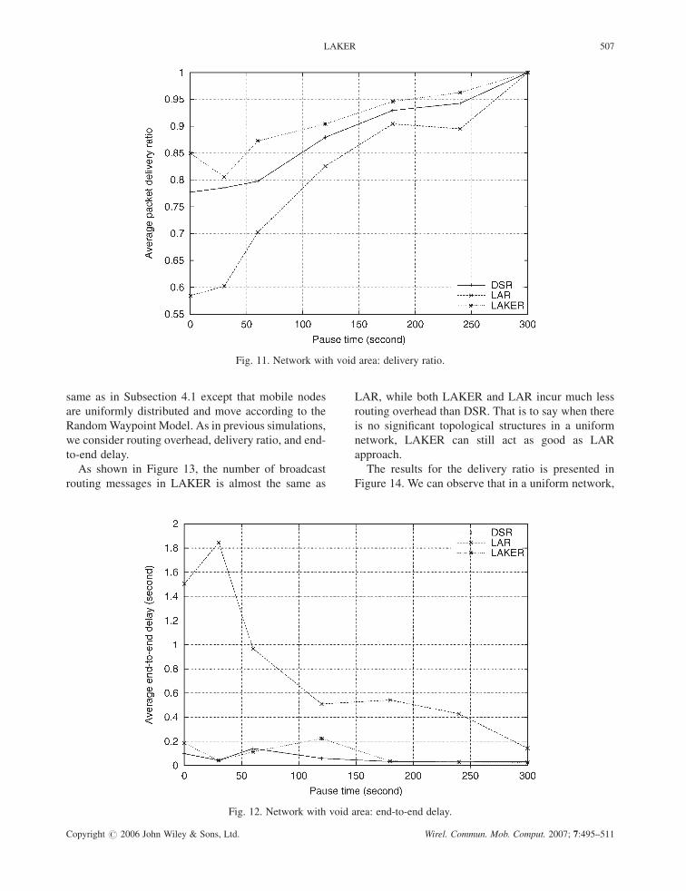
Second, Figure 11 shows the packet delivery ratio.
We observe that LAKER outperforms both DSR and
LAR. LAR achieves worse delivery ratio than DSR in
all pausetimes. We believe that LAKER performs
better because it successfully reduces the broadcasting
overhead, which translates to fewer collisions and
higher delivery ratio. The reason that LAR delivers
much less traffic is twofold. On one hand, its higher
routing overhead (at low pausetime cases) can result
in more transmission collisions. On the other hand,
more importantly, LAR process of expanding ring
search incurs too much delay in route discovery,
which may lead to many data packets’ drop-off due
to lifetime expiration.
Third, as shown in Figure 12, LAKER achieves
almost the same end-to-end delay as DSR. However,
LAR shows much higher end-to-end delay than
both DSR and LAKER. Since transmission time
should be basically the same in all three protocols,
the end-to-end delay is mainly due to the waiting time
for new routes to be discovered. This again demon-
strate s that LAR route discovery process incurs too
much delay in presence of void areas in the network.
As a summary for this sub-section, in presence of
void areas in the network, LAR may end up with poor
performance without any knowledge of the topology.
On the contrary, LAKER can bypass the void areas
using discovered guiding information, and achieve
better routing performance than LAR and DSR.
4.3. Uniform Network
We also run simulations in networks with uniform
node distributions. The network area is 1200� 1200
square meters. All the simulation parameters are the
Fig. 9. Simulation mobility model II: a network with voidarea.
Fig. 10. Network with void area: number of broadcast routing messages.
506 J. LI AND P. MOHAPATRA
Copyright # 2006 John Wiley & Sons, Ltd. Wirel. Commun. Mob. Comput. 2007; 7:495–511
same as in Subsection 4.1 except that mobile nodes
are uniformly distributed and move according to the
RandomWaypoint Model. As in previous simulations,
we consider routing overhead, delivery ratio, and end-
to-end delay.
As shown in Figure 13, the number of broadcast
routing messages in LAKER is almost the same as
LAR, while both LAKER and LAR incur much less
routing overhead than DSR. That is to say when there
is no significant topological structures in a uniform
network, LAKER can still act as good as LAR
approach.
The results for the delivery ratio is presented in
Figure 14. We can observe that in a uniform network,
Fig. 11. Network with void area: delivery ratio.
Fig. 12. Network with void area: end-to-end delay.
LAKER 507
Copyright # 2006 John Wiley & Sons, Ltd. Wirel. Commun. Mob. Comput. 2007; 7:495–511

both LAKER and LAR achieve almost the same
performance as DSR. As the pausetime increases,
network mobility decreases and all the three protocols
achieve a higher delivery ratio. Figure 15 shows the
end-to-end delay. On an average, all the three proto-
cols achieve almost the same end-to-end delay.
In summary, we observe that LAKER performs
almost the same as LAR in a uniform network. This
is because, by design, LAKER will degrade to LAR
when there is no topological structure in the network.
However, in the presence of any topological non-
uniformity, LAKER outperforms both DSR and LAR.
Fig. 13. Uniform network: number of broadcast routing messages.
Fig. 14. Uniform network: delivery ratio.
508 J. LI AND P. MOHAPATRA
Copyright # 2006 John Wiley & Sons, Ltd. Wirel. Commun. Mob. Comput. 2007; 7:495–511

5. Related Work
Mobility modeling and location guided routing
have gained much attention from researchers
recently. A survey on mobility models in ad hoc
networks can be found in Reference [3], and a number
of position-based routing protocols are summarized in
Reference [2]. Here we only discuss a few efforts that
are closely related to our work.
LANMAR routing protocol [19] attempts to
exploit the network characteristics aiming at addres-
sing the scalability problem. The protocol adopts a
‘Reference Point Group Mobility’ model and attempts
to keep track of logical subnets in which the members
have a commonality of interests and are likely to move
as a ‘group.’ LAKER is different from LANMAR in
that it attempts to keep track of the population
density distribution of the network, aiming at reducing
routing overhead by means of better guidance in route
discovery.
The restricted random waypoint mobility model
we adopt in this paper was proposed in Reference
[4]. The authors of Reference [4] also proposed
an ‘Anchored Geodesic Packet Forwarding’ approach
to solve the problem of ‘void’ area in the network.
As proposed in Reference [4], the knowledge of
‘anchored path’ is generated with assistance from
a set of friend nodes in the network, or based on a
predefined map of population density. When forward-
ing data packet,‘anchored path’ is used as loose
source routing information, which is similar to our
notion of ‘guiding route.’ Our work is different from
Reference [4] in the sense that we use a different way
to generate and utilize this guiding information. In
particular, LAKER can gradually discover partial
knowledge of the network characteristics in route
discovery phase, and smartly use this information to
guide future route discovery processes.
GFG routing protocol proposed in Reference [12]
can achieve guaranteed delivery in unicasting, broad-
casting, and geocasting in ad hoc networks. A
major feature of GFG is that it does not require
duplicate message or persistent use of memory of
any node during message delivery. Based on a static
and connected topology, the authors showed the
correctness of the protocol, even in face of a ‘void’
area where all neighbors are further away towards
the destination. Another protocol proposed in
Reference [13], named GPSR routing protocol,
also aggressively uses geographical location informa-
tion in making routing decision. When an intermedi-
ate node receives a packet, it will greedily forward
this packet to one of its neighbors, which can mostly
reduce the distance towards the destination node.
When a packet is stuck at some intermediate node
due to the existence of ‘void’ area in the network, a
perimeter routing technique is applied to find a
bypassing route towards the destination.
Fig. 15. Uniform network: end-to-end delay.
LAKER 509
Copyright # 2006 John Wiley & Sons, Ltd. Wirel. Commun. Mob. Comput. 2007; 7:495–511

6. Conclusion
In this paper, we present a LAKER protocol for
MANETs. In mobility models where nodes are
not uniformly distributed, LAKER can gradually dis-
cover topological characteristics of the network, such
as population density distribution, during the route
discovery process. This kind of knowledge can be
organized in the form of a set of guiding routes, and
can be used to guide future route discovery processes
more precisely and more efficiently. Simulation
results show that, in networks with non-uniform
node population distributions, LAKER can save up
to 30–45% broadcast control messages compared
to LAR approach, while achieving higher delivery
ratio and similar or better end-to-end delay. In
the presence of void areas in the network, LAKER
can smartly direct its route discovery process to
bypass the void area and thus achieve much better
performance than DSR and LAR approach.
The key feature of LAKER is that it learns from
past actions to improve future performance. In our
simulations, we only use population density distribu-
tion and a lake as void area for demonstration. It is
also possible for LAKER to discover other topological
characteristics such as residual energy map and
current traffic load. LAKER can be considered as
a generic approach for knowledge discovery and
knowledge guided routing in wireless ad hoc net-
works.
Acknowledgment
This research was supported in part by the National
Science Foundation through the grants CCR-
0296070 and ANI-0296034, and a generous gift
from Hewlett-Packard Corporation. The authors
also thank the anonymous reviewers for their valu-
able comments and input which helped improve the
quality of this paper.
References
1. Royer EM, Toh CK. A review of current routing protocolsfor ad-hoc mobile wireless networks. IEEE Personal Commu-nications 1999; 6(2): 46–55.
2. Mauve M, Widmer J, Hartenstein H. A survey on position-based routing in mobile ad hoc networks. IEEE NetworkMagazine 2001; 15(6): 30–39.
3. Camp T, Boleng J, Davies V. Mobility models for ad hocnetwork simulations. Wireless Communication & MobileComputing (WCMC): Special issue on Mobile Ad HocNetworking: Research, Trends and Applications, 2002; 2(5):483–502.
4. Blazevic L, Giordano S, Boudec JL. Self organization inmobile ad hoc networks: the approach of Terminodes. IEEECommunications 2001; 39(6): 166–174.
5. Elmallah E, Hassanein H, AboElFotoh H. Supporting QoSrouting in mobile ad hoc networks using probabilistic localityand load balancing. In Proceedings of IEEE GLOBECOM2001.
6. Yoon J, Liu M, Nobel B. Random waypoint considered harm-ful. In Proceedings of IEEE INFOCOM 2003; pp. 1312–1321.
7. Jardosh A, Belding-Royer EM, Almeroth KC, Suri S. Towardsrealistic mobility models for mobile ad hoc networks. InProceedings of ACM MOBICOM 2003; pp. 217–229.
8. Johnson DB, Maltz DA, Broch J. DSR: The dynamic sourcerouting protocol for multi-hop wireless ad hoc networks. InAd Hoc Networking, Perkins CE (ed.). Addison-Wesley:Boston, MA, USA, 2001.
9. Perkins CE, Royer EM. Ad hoc on-demand distance vectorrouting. In Ad Hoc Networking, Perkins CE (ed.). Addison-Wesley: Boston, MA, USA, 2001.
10. Ko YB, Vaidya NH. Location-aided routing (LAR) in mobilead hoc networks. ACM/Baltzer Wireless Networks (WINET)journal 2000; 6(4): 307–321.
11. Basagni S, Chlamtac I, Syrotiuk VR, Woodward BA. Adistance routing effect algorithm for mobility (DREAM).In Proceedings of ACM MOBICOM 1998; pp. 76–84.
12. Bose P, Morin P, Stojmenovic I, Urrutia J. Routing withguaranteed delivery in ad hoc wireless networks. ACMWirelessNetworks 2001; 7(6): 609–616; In Proceeding of 3rd ACMInternational Workshop DIAL-M, Seattle, August 20, 1999;pp. 48–55.
13. Karp B, Kung HT. GPSR: Greedy perimeter stateless routingfor wireless networks. In Proceedings of ACM MOBICOM2000; pp. 243–254.
14. McNeff JG. The global positioning system. IEEE Transactionson Microwave Theory and Techniques 2002; 50(3): 645–652.
15. Bulusu N, Heideimann J, Estrin D. GPS-less low cost outdoorlocalization for very small devices. IEEE Personal Commu-nications Magazine 2000; 7(5): 28–34.
16. Capkun S, HamdiM, Hubaux J. GPS-free positioning in mobilead hoc networks. In Proceedings of the 34th HICSS, Vol. 9,2001.
17. Li J, Jannotti J, Decouto D, Karger D, Morris R. A scalablelocation service for geographic ad-hoc routing. In Proceedingsof ACM MOBICOM, 2000.
18. Broch J, Maltz DA, Johnson DB, Hu YC, Jetcheva J. Aperformance comparison of multi-hop wireless ad-hoc networkrouting protocols. In Proceedings of ACM MOBICOM 1998,pp. 85-97.
19. Gerla M, Hong X, Pei G. Landmark routing for large ad hocwireless networks. In Proceedings of IEEE GLOBECOM,2000.
20. The Network Simulator ns-2, available online at http://www.isi.edu/nsnam/ns/.
21. The Monarch Group at Rice University, http://www.monarch.cs.rice.edu/.
510 J. LI AND P. MOHAPATRA
Copyright # 2006 John Wiley & Sons, Ltd. Wirel. Commun. Mob. Comput. 2007; 7:495–511

Authors’ Biographies
Jian Li is a Ph.D. candidate in theDepartment of Computer Science atthe University of California, Davis.His research interests include wirelessnetworking and mobile computing.Li received his M.S. in ComputerScience from UC Davis in 2002, hisM.Eng. in Intelligent System, and aB.Eng. in Automatic Control, bothfrom Tsinghua University, Beijing,China, in 2000 and 1997, respectively.
Dr Prasant Mohapatra is currently aprofessor in the Department of Com-puter Science at the University ofCalifornia, Davis. He has also heldvarious positions at Iowa State Univer-sity, Michigan State University, IntelCorporation, Panasonic Technologies,Institute of Infocomm Research, Sin-
gapore, and the National ICT, Australia. Dr Mohapatrareceived his Ph.D. in Computer Engineering from thePennsylvania State University in 1993. He was/is on theeditorial boards of the IEEE Transactions on Computers,ACM/Springer WINET, and Ad hoc Networks Journal. Hehas served on numerous technical program committees forinternational conferences, and served on several panels. Hewas the Program vice-chair of INFOCOM 2004, and theProgram co-chair of the First IEEE International Confer-ence on Sensor and Ad Hoc Communications and Net-works (SECON-2004). Dr Mohapatra’s research interestsare in the areas of wireless networks, sensor networks,Internet protocols, and QoS
LAKER 511
Copyright # 2006 John Wiley & Sons, Ltd. Wirel. Commun. Mob. Comput. 2007; 7:495–511