laadullinen tutkimus - theseus
TRANSCRIPT

Ilpo Mettovaara
DFMA – PROCESS DEVELOPMENT IN SASKEN FINLAND OY

DFMA – PROCESS DEVELOPMENT IN SASKEN FINLAND OY
Ilpo Mettovaara Master’s Thesis Autumn 2010 Degree Programme in Industrial Management Oulu University of Applied Sciences

3
ABSTRACT Oulu University of Applied Sciences Degree Programme in Industrial Management Author(s): Ilpo Mettovaara Title of thesis: DFMA – Process Development in Sasken Finland Oy Supervisor(s): Mikko Ylimaula, Mikko Keskilammi, Kyösti Kataja Term and year when the thesis was submitted: Autumn 2010 Number of pages: 37 ABSTRACT
The objective of this research was to develop the DFMA process for mechanics engineers and to link it into the product development (PD) process of the Sasken Finland Oy. To develop guidelines, checklist, etc. tools for mechanics engineers to help them in their design work, documentation and reporting. One of the big objectives was to create the DFMA process required by one of the main customers.
This research addresses on DFM (Design for Manufacturability) and DFA (Design for Assembly) engineering theories and implementing these theories in practice. DFM takes into consideration possibilities and limits of certain manufacturing processes and aims at designing parts which are easy to fabricate and produce. DFA takes into consideration possibilities and limits of assembly processes and aims at designing assemblies or products that are easy to assemble and produce.
This research was done and the future development will be done at the Sasken Finland site. The research was done in a group of seven mechanics engineers. The research method was the so called Action Method.
As a result of this research DFMA process for mechanics, design guidelines, design checklists and DFMA analyze template will be taken into use at least at the Beijing and Bangalore sites.
The DFMA process and documentation will be yearly updated and developed under the Sasken Finland Research and Capability management.
Keywords: Product Design, Design for Manufacturability / Assembly, Concurrent Engineering

4
1 INTRODUCTION ........................................................................................... 5
1.1 Subject Matter .................................................................................... 5 1.2 Objective ............................................................................................ 7 1.3 Definition ............................................................................................ 7 1.4 Theoretical Background ...................................................................... 8 1.5 Research Method ............................................................................... 8
1.5.1 Research Scope....................................................................... 8 1.5.2 Methods of Data Collection ...................................................... 8
2 DFMA AND CONCURRENT ENGINEERING ............................................. 10
2.1 DFM / DFA ....................................................................................... 10 2.2 Concurrent Engineering .................................................................... 11 2.3 DFX Design for Everything ............................................................... 12
3 OUTCOME .................................................................................................. 18
3.1 DFMA Guideline for Mechanics ........................................................ 18 3.2 DFMA Check Lists ............................................................................ 19 3.3 DFMA Analysis ................................................................................. 21 3.4 DFMA Lecture .................................................................................. 33
4 CONCLUSION ............................................................................................ 34
5 CONTEMPLATION ..................................................................................... 35
REFERENCES ................................................................................................... 36
APPENDIXES .................................................................................................... 37

5
1 INTRODUCTION
1.1 Subject Matter
This research was commissioned by my employee Sasken Finland Oy and is
part of the global HW Resource and Capability development.
Sasken Finland Oy is a subsidiary of Sasken Communication Technologies
Ltd., a global leader in R&D and support services to companies across the
communications value chain. Sasken provides products and services to leading
semiconductor, terminal device, network equipment and test and measurement
companies, and service providers globally. Established in 1989, the company
has over 3,500 associates, and operates out of offices in India, China, France,
Finland, Germany, Japan, Mexico, UK and the U.S.
Sasken Finland Group is a service provider for companies wishing to generate
winning products and services in the rapidly growing wireless technology area.
Sasken Finland’s vision is to be a leading product and solution design company
for wireless applications. The employees are highly trained experts. Most of
them have advanced degrees and are experienced in their field. They are
continuously developing their knowledge. The driving force is to be innovative
and solution oriented.
HW Business Line is a division specializing in wireless technology products
offering hardware and mechanical design services and solutions with a
particular strength in RF-design know-how. It also includes testing services and,
therefore, offers a one stop shop method for testing and is capable of testing
whole products with the main focus on R&D testing of wireless technology
products.
SW Business Line is a division focusing on software engineering, integration &
consulting. It represents the top knowledge of the industry in mobile software
development. SW Business Line is continuously involved in several demanding

6
software projects - that ensures durable competence, which can be leveraged
for your benefit. (http://www.sasken.fi/company_profile.htm 27 Oct. 2009)
The research addresses on DFM (Design for Manufacturability) and DFA
(Design for Assembly) engineering theories and implementing these theories in
practice. DFM takes into consideration possibilities and limits of certain
manufacturing processes and aims at designing parts which are easy to
fabricate and produce. DFA takes into consideration possibilities and limits of
assembly processes and aims at designing assemblies or products that are
easy to assemble and produce.
These two definitions are very narrow and simple explanations of quite complex
issues. These two philosophies or theories are more or less mixed, and go side
by side and are very much connected to each other. Because of this, in many
contexts, these two issues are under the letters DFM, DFA or DFMA. There are
also some letter combinations to describe some special processes like DFBA,
Design for Board Assembly. Or DFFA Design For Final Assembly.
In my research I have decided to use letters DFMA, which I think, is the best
way of describing the issues. Dr. David M. Anderson describes in his book:
DFM is the process of proactively designing products to: (a) optimize all the manufacturing functions: fabrication, assembly, test, procurement, shipping, service and repair; and (b) assure the best cost, quality, reliability, regulatory compliance, safety, time-to-market, and customer satisfaction; and (c) ensure that lack of manufacturability doesn’t compromise functionality, styling, new product introductions, product delivery, improvement programs, strategic initiatives and unexpected surges in product demand. (Anderson 2008)
In my opinion it is alright to talk about DFMA as “Design for all”. DFMA is not a
new invention but it is a thing that rarely is focused systematically on product
development processes. This was also one of my basic assumptions at the very
beginning of the study and also was confirmed later on by interviews with
designers.
7
1.2 Objective
The objective of this research was to develop a DFMA process for a mechanics
engineering group and link it into the product development (PD) process, as
were as, to develop guidelines, checklists, etc. tools for mechanics engineers to
help them with design work, documentation and reporting.
One of the main objectives was to create a DFMA process required by one of
the main customers. They were developing their own DFM capabilities and
competencies and were also setting requirements for suppliers. The customer
was committed to the DFMA process development, giving their support and
arranged DFMA training to the company’s management and mechanics team.
1.3 Definition
Issues included in this research are as follows:
1. To get knowledge from DFMA issues
2. To get understanding of the level of DFMA capabilities and competencies
among mechanics engineers, by means of interviews
3. To find out a way to join the DFMA process part of the PD process
4. To develop guidelines, checklists, etc. to ease DFMA design work and
documentation for mechanics engineers
6. To arrange an internal DFMA course for mechanics engineers, containing
use of documents created during this development process and how to join
DFM issues in the PD process
8
1.4 Theoretical Background
The literatures mainly used in this research are as follows:
Dr. David M. Anderson; Design for Manufacturability & Concurrent Engineering,
2008
Boothroyd and Dewhurst DFM methods, 1983
1.5 Research Method
1.5.1 Research Scope
This research was carried out at the company’s site here in Finland, in a
mechanics engineering group consisting of seven mechanics engineers. The
Research method is the so called Action Method. Future development work will
be done together with the company’s sites in Finland, Bangalore and Beijing.
Sasken Finland has already had some co-operation with the Bangalore site.
The outputs from this research are as follows: DFMA process for mechanics,
DFMA Guideline for Mechanics document, DFMA Appendix 1 Assembly Check
List document, DFMA Appendix 2 Part Design Check List document, DFMA
Analyze Template document and DFMA Analyze lecture material and lesson
from the DFMA process and new tools for Mechanics Engineers.
In the future the DFMA process and documents will be employed and used at
least at the Beijing and Bangalore sites.
1.5.2 Methods of Data Collection
There were two interview rounds among the mechanics engineers. The first
round was arranged to get understanding of what the level of DFMA capabilities
and competencies among the mechanics engineers was. How they saw the
DFMA issues were taken care of and what kind of ideas they had to improve the
9
situation. In my opinion this was one of the most important phases of this
research. This way the engineers were involved in this development process,
their ideas were listened and recorded. They got an opportunity to affect the
coming process. The second round was to track the situation after they had
participated in the customer’s DFM course, they had been familiarized with the
guidelines, checklist, etc. tools, and they had participated in an internal course.
The interviews were open conversations in person between the author and a
mechanics engineer. In the interviews a few open questions were used to keep
the conversation in track and to have comments to the same issues from
everyone. (Appendix 1) Conversations were recorded and analyzed. The
records are in the hands of the author.
As a member of the mechanics engineering group I had a very good position to
make observations about the following: How DFMA is understood, how it was
taken care of in practice and what happened during the process. Many times
during this study I ended up in a situation where someone pointed out some
DFMA related issue to me, or I got an opportunity to point out some issues that
were related to DFMA.
Theoretic data was collected from literature, different kinds of publications, the
internet and the customer’s training material.

10
2 DFMA AND CONCURRENT ENGINEERING
2.1 DFM / DFA
Engineers are generally not taught DFM or concurrent engineering at college –
the focus is usually on how to design for functionality. Further, they are typically
trained to design parts, not products or systems. Most design courses do not
even talk about how the parts are to be manufactured. And engineering
students rarely follow through designs to completion to get feedback on the
manufacturability of their designs. (Anderson 2008)
This is one of the main problems that were also found out in this research.
Based on the interviews and my own experience I can agree with Dr. Anderson.
The first interview round showed that new engineers did not seem to have so
much knowledge about DFM or DFA as more experienced engineers had. It
was also noticed that the engineers who had been actively working in R&D
programs with the customer, had good or very good knowledge about DFM/A
issues. This tells that these issues are learnt in working life and real product
development tasks. It was also noticed that all the engineers had more
understanding about DFM than DFA. This way that can be understood easily. It
is more common that DFM issues are taken care of in R&D projects than DFA
issues. I think it is more natural to take care of DFM with the part supplier,
maybe not under DFM letters but as some kind of “Design Feedback”.
Because DFMA knowledge seemed to be very much dependent on the
persons` working history, some of them knew more than the others, and
because the company was not having a certain process for DFMA, these DFMA
issues were more or less taken care of by individual engineers, handled and
based on the persons` “gray information”, if they were. According to my
experience DFMA issues were not the first thoughts in mind when a new
product was designed, but functionality, reliability, and demand for marketing
and industrial design and keeping schedules. It happened many times that all
constrains were already locked when a production engineer and/or a part
supplier gave feedback of manufacturability or assembly. As we all know in this

11
phase, maybe just before the file release, it is a bit too late to start thinking
about DFMA.
On the other hand, when the DFMA issues are not in a systematic process,
product development managers usually stress schedule and cost, but, if not
measured right, may further reinforce the suboptimal behavior described above.
Pressuring engineers to complete tasks “on schedule” is really telling them to
“throw it over the wall on-time”. In reality, the most important measure of
schedule is the time within the product has ramped up to stable production and
is satisfying all the customers who want to buy the product. (Anderson 2008)
2.2 Concurrent Engineering
“Throw over the wall” effect can be caused either by schedule oriented design
process, lack of systematic DFMA work or cultural fact, “we are designing the
product, DFMA is the supplier’s problem”. Here we come to another very
important thing; Concurrent Engineering. Concurrent Engineering is the
proactive practice of designing products to be built in standard processes, or
concurrently developing new processes while concurrently developing new
products. If existing processes are to be utilized, then the product must be
designed for the processes. If new processes are to be utilized, then the
product and the process must be developed concurrently. This requires a lot of
knowledge about manufacturing processes and one of the best ways of doing
so is to develop products in multifunctional teams. The most critical factor in the
success of Concurrent Engineering is the availability of resources to form
multifunctional teams with all specialties present and active early. (Anderson
2008)
I would like to open this Concurrent Engineering a little bit more. When we talk
about Concurrent Engineering at a single part design level, we can either
design the part for existing technology, e.g. a plastic part for injection molding,
just following the design guidelines and having a discussion with the part
supplier. In this case the DFM and Concurrent Engineering would be at the
simplest level. Or we can design the part and develop the new a technology to
make the part. In this case Design House and Part supplier work together as a

12
team; concurrently. Still we can only say that DFM is done concurrently, not yet
DFA. When we go into a more wider perspective, not just designing a part, but
designing a product, we need a more wider range of expertise, e.g. in a handset
we need: mechanics designers, PWB layout designers, RF designers, audio
designers, HW designers, industrial designers, marketing, management,
graphical designers, etc, all this from a design house and when we go further
we need tool designers from part suppliers, production engineers and
operators, preproduction, etc. When all of them are working together as a team,
we can speak about high level Concurrent Engineering.
During the interviews the engineers often mentioned co-operation, co-operation
with part suppliers and material suppliers. The engineers seem to know and
understand DFM and the importance of DFM. Often, when they were asked to
describe DFMA, they were actually describing DFM, which, in my opinion, is
only a half of DFMA. Also our customer highlighted this issue, they have had
situations when they have arranged DFA training for their part suppliers and
they have asked part suppliers to describe DFA, part suppliers have actually
described DFM issues. In the interviews the engineers often were also talking
about concurrent engineering inside the design house, many times concurrent
engineering was limited in the design house and did not reach the part suppliers
or other partners.
2.3 DFX Design for Everything
Engineers are trained to design for functionality and their CAD tool
predominantly designs for functionality. However, really good product
development comes from designing for everything, which is sometimes called
DFX. Here is a list of design considerations for Design for Everything. The key
here is to consider all goals & constrains at the early stage of the PD process.
Function. Of course the product has to work properly, but it must be kept in
mind that, although, function is the most obvious consideration, it is far from
being the only one.

13
Cost. Cost has been the battlefield of competition for decades now. Design
determines more than three fourths of cost of a product.
Delivery. Delivery is greatly affected by the product design, because the design
determines how difficult it is to build and assemble. The choice and the design
of parts determine how hard it is to produce the parts and how vulnerable
production is when supplying glitches. Standardization and staying within well-
known materials and technologies affect the effectiveness of lean production,
which is the key of a fast factory throughput.
Quality and reliability. Like cost, quality and reliability are determined more by
design than is commonly realized. Designers specify the parts and, thus, the
quality of the parts. Designers determine the number of parts and this way
determine the cumulative effect of part quality on product quality, which is
especially important for complex products. Designers are responsible for
tolerance sensitivity. The processes specified by designers determine the
inherent quality of the parts. Designers are responsible for ensuring that parts
are designed so that they cannot be assembled wrong, which in Japan is called
poka-yoke, or what we would call mistake-proofing. These are very much DFM
issues since quality problems must be consistently corrected at plants before
products can be shipped.
Ease of assembly. Ease of assembly is one of the main targets of DFMA, and
also one of the main focus areas of this research. There is a method developed
by Boothroyd and Dewhurst; Boothroyd and Dewhurst DFM methods, 1983.
Also software to analyze designs to look for opportunities to improve the
assembly of high volume products. More about this later in chapter 3.3.
Ability to test. Test strategy is very much affected by the company quality
“culture”. In companies with good quality culture, quality is everyone’s
responsibility, including designers. The TQM (Total Quality management)
philosophy is that, instead of being tested in, quality should be designed in and
then built in by using process controls. Theoretically, products need not to be
tested if all processes are 100% in control. However, few factories are that
confident and in real life designers are responsible for devising ways of not only
testing products but, also diagnosing them if needed by the factory. As to

14
complex products, test development costs can exceed product development
costs and even take more calendar time.
Ease of service and repair. Being able to repair a defective product is a DFMA
issue because any product failing any test will have to be repaired, thus
consuming valuable manufacturing resources. Service and repair in the field
can be more troublesome because field service centers usually have less
sophisticated equipment than factories. In extreme cases, field failures may be
sent back to the factory for repair, thus diluting manufacturing recourses.
Supply Chain management. Supply chain management can be greatly
simplified by the standardization of parts and raw materials, by part selection
based on adequate availability over time, and by product line rationalization to
eliminate or outsource the, low volume, unusual products that have the most
unusual parts. In many cases, this simplification, performed in product portfolio
planning and product development, is essential to the success of supply chain
management initiatives as well as programs to implement lean production,
build-to-order, and mass customization.
Shipping and distribution. The distribution of products will be revolutionized
by build-to-order, which is capable of building products on-demand and shipping
them directly to customers, stores, or other factories instead of the mass
production tradition of building huge batches and then shipping them through
warehouses and distribution centers. Packaging considerations should not be
left a side until the first manufactured product reaches the shipping dock.
Packaging variety and its logistics can be reduced with standard packaging that
can be used for many products. Unique information can be added by printing
on-demand labels or directly onto the boxes. Environmentally friendly packaging
materials and recycled packages are now becoming more important.
Human factors. Human factors and ergonomics are social considerations that
should be considered in the very beginning, since ergonomic changes would be
difficult to implement after the design has been complete. Good human factors
in the design of a product and a process will reduce errors and accidents in use
and during manufacture. In some industries e.g. the electronics industry, many
service calls are made to correct customer setup and operation errors.

15
Appearance and style. Appearance and style should be considered an integral
part of the design, not something that is added later. Sometimes, the style
dictated by an early industrial design study. This can really hamper
incorporating DFMA principles if these were not considered in the “styling”
design. All factors of design, including styling, need to be considered
simultaneously throughout the design.
Safety. Safety should not be considered after the recall of the first law suit.
Careful design and simulation should be utilized to prevent safety problems
before they would manifest. If a safety issue appears, the root of the problem
must be determined and remedied immediately. This can be a major disruption
to Engineering, Manufacturing, and Sales, in addition to jeopardizing the
reputation of the product and the company. Designers should make all they can
to design safe products from the start as their moral and legal obligation.
Customer’s needs. The ultimate goal in designing a product is to meet the
needs of the customer. In order to do that, designers must thoroughly identify
and understand customer needs and then systematically develop the product to
meet those needs. Engineers must be beware of the “next bench syndrome”
and avoid designing products for themselves or their peers.
Breadth of product line. When the principles of lean production and build-to-
order are used, products can be designed with standard parts and produced on
flexible manufacturing lines or cells. Common parts, standard design features,
modular subassemblies, and flexible manufacturing can be combined to satisfy
more customers.
Product customization. Customized products can be built as quickly and
efficiently as in mass production if products and processes are designed for
mass customization.
Time-to-market. Time-to-market is a major source of competitive advantage. In
fast moving markets, being the first to the market can be a major market share
implication.
Expansion and upgrading. Designers should design their products so that
they are easy to expand or upgrade by the plant or by the customer. This
possibility may allow the company to increase profits by extending the lifetime of

16
each product. Marketing and finance representatives should be involved at an
early stage to help formulate the product upgrading strategy and calculate its
value.
Future designs. Similarly, current products should be designed so that
subsequent products can be based largely on current designs. This would save
much time and cost in the next design if the maximum use can be reached by
employing current engineering, parts, modules, and software.
Product pollution. Environmental design considerations should not be left
aside when a product or its process is fired up for the first time. Problems
discovered at this stage may require major changes or a redesign to be
corrected. Designers should anticipate environmental trends and design
products clean enough for future environmental standards.
Processing pollution. Product designers specify the process whether they
realize it or not. Even if a usual process is specified, it may continue with a
process causing pollution from solvents, combustion products, chemical waist,
and so forth. Designers of new products have the opportunity of optimizingg the
environmental cleanliness of processes. This is much easier to do at the early
stages of design than later. Do not wait until environmental activists or a
regulatory agency force your company to change your processes, which would
result in disruptive changes in the factory, costly penalties, engineering change
orders, and maybe a product redesign.
3M Corporation formulated an environmental strategy called the 3P program:
“Pollution Prevention Pays”. The theme is prevention of pollution at its source.
The three elements of the program are: 1 Recycling, 2 Redesign products and
equipment for less pollution and 3 Create products that do not pollute in the first
place.
Note that two out of three methods depend on the design to reduce pollution.
Ease of recycling the products. Similarly, companies should be concerned
about what happens to the product after its useful lifetime is over. Can it be
recycled into a new product? Can it be upgraded for extended lifetime?
All these DFXs should be emphasized early enough by product development
teams since redesigns or major product design changes consume a great deal

17
of design and manufacturing resources to implement the changes. Remember
that changes and redesigns consume the engineering time and money that
should be invested in new product development.
18
3 OUTCOME
One of the main targets of this research was to develop, as an outcome,
guidelines, checklists, etc. documents to ease DFMA design work and
documentation of mechanics engineers. During the interviews the engineers got
an opportunity to share their ideas and thoughts for future documents and
processes. DFMA Guideline for Mechanics (appendix 3) includes three
appendixes: DFMA Appendix 1 Assembly Check List, DFMA Appendix 2 Part
Design Check List and DFMA Analyze Template were developed to serve four
purposes. First to work as a short introduction into DFMA issues. Secondly to
help Mechanics Engineers during a product development process to design and
to optimize the product design for manufacturability and assembly. Thirdly,
finalized documents DFMA Appendix 1 Assembly Check List, DFMA Appendix
2 Part Design Check List are part of the Product Development process
documentation. Fourthly, DFMA Analyze template (appendix 3) is used to
evaluate, compare and develop a certain assembly or product and collect data
for DFMA metrics.
3.1 DFMA Guideline for Mechanics
DFMA Guideline for Mechanics document (appendix 3) works as a short
introduction into DFMA issues, this is something that especially young
engineers need. To help mechanics engineer during the product development
process to design and to optimize the product design for manufacturability and
assembly. In the document there is shortly explained what DFMA is and what it
is not. In the document there are key principles of DFMA and the generic
guidelines of DFMA for a product development process. Short and simple
examples, how you can optimize the design from the point of view of DFMA.
The document also includes chapters for the different phases of the PD
process. What should be considered in the concept/architecture phase? What

19
should be considered in product design, integration and verification phases?
Type approval and certification phase? Volume production phase?
The DFMA Guideline for Mechanics document including current and coming
appendixes is authored, reviewed and updated every year under HW Recourse
and Capability Management.
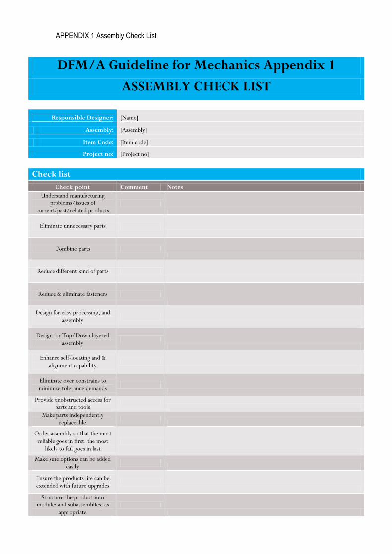
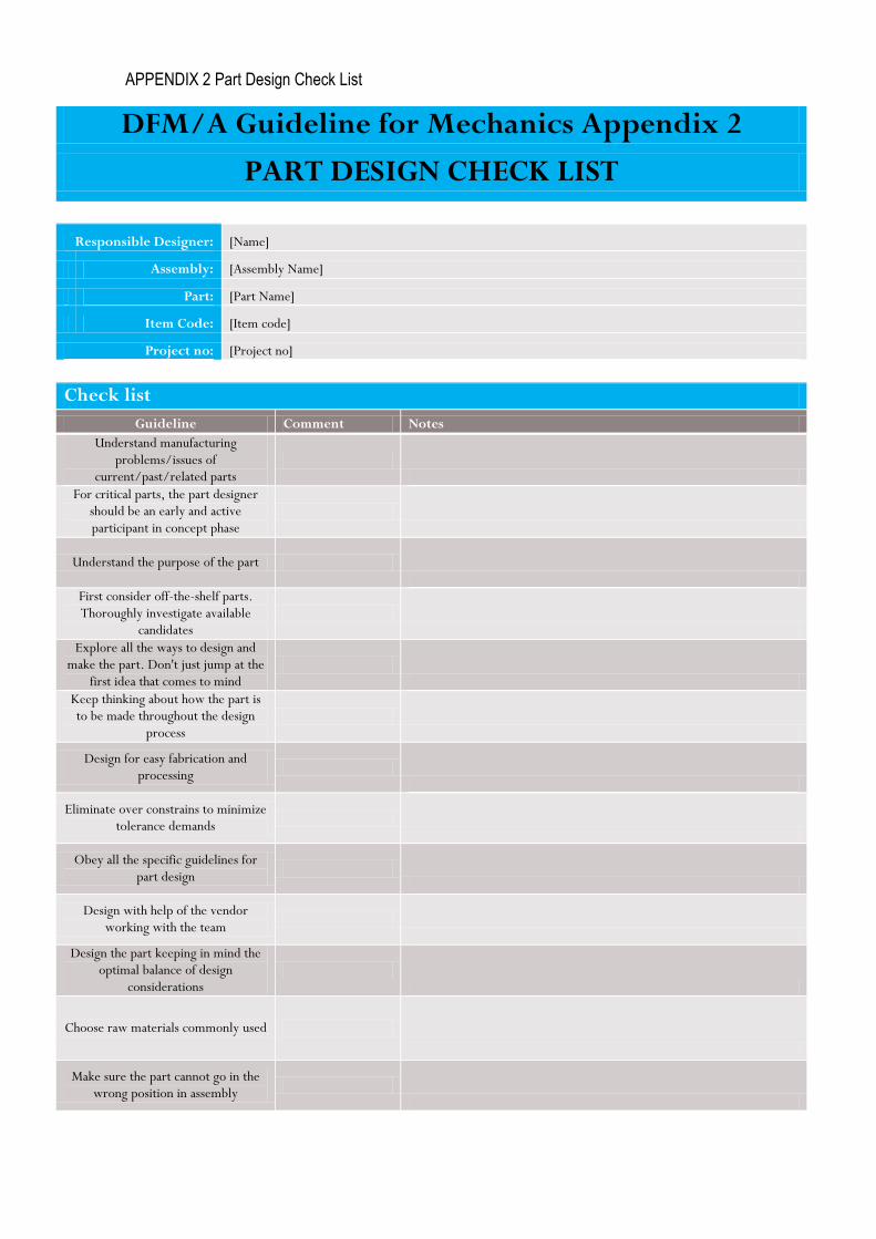
3.2 DFMA Check Lists
As part of the DFMA Guideline for Mechanics, there are DFMA Appendix 1
Assembly Check List and DFMA Appendix 2 Part Design Check List documents
which were developed to work as check lists for mechanics designers during
the PD process, to give some very practical check points, in the question form,
not to control too tightly the design but more likely to work as an inspiration to
the right direction.
These check lists also work as documents from the DFMA work done. In the
check list a responsible designer gives comments OK, NOK or N/A based on
how the designer sees the current check point is fulfilled. The designer also
gives short comments on every check point, how the OK stage is exceeded or
why some check point is in NOK or N/A stage. (pictures 1 and 2)

20
PICTURE 1
PICTURE 2
21
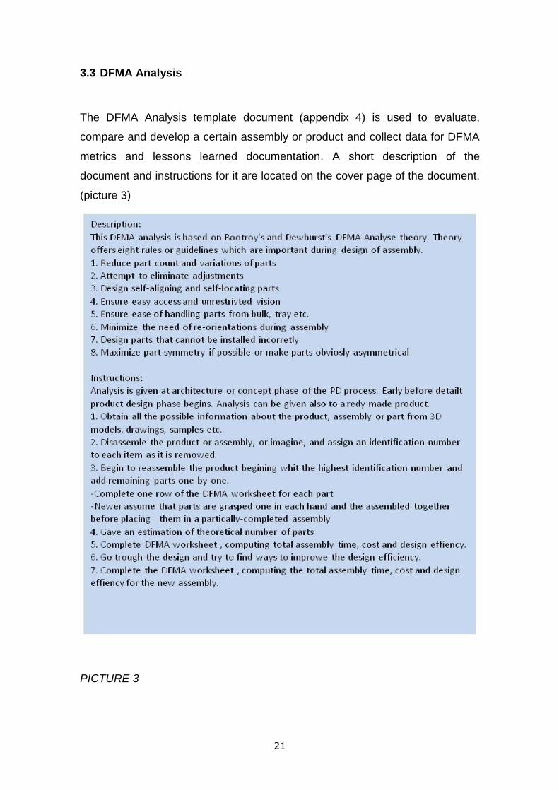
3.3 DFMA Analysis
The DFMA Analysis template document (appendix 4) is used to evaluate,
compare and develop a certain assembly or product and collect data for DFMA
metrics and lessons learned documentation. A short description of the
document and instructions for it are located on the cover page of the document.
(picture 3)
PICTURE 3

22
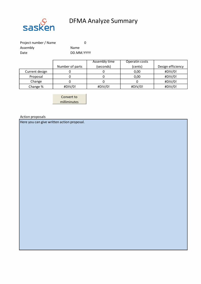
On the summary page there is the a field (picture 4) including all the important
numerical information needed to evaluate and to compare one assembly with
another. This information is used to support decision making, and to collect
numerical information. The idea is to minimize the number of parts and
subassemblies in the main assembly, in this way to minimize assembly and
operating time and operating costs.
PICTURE 4

23
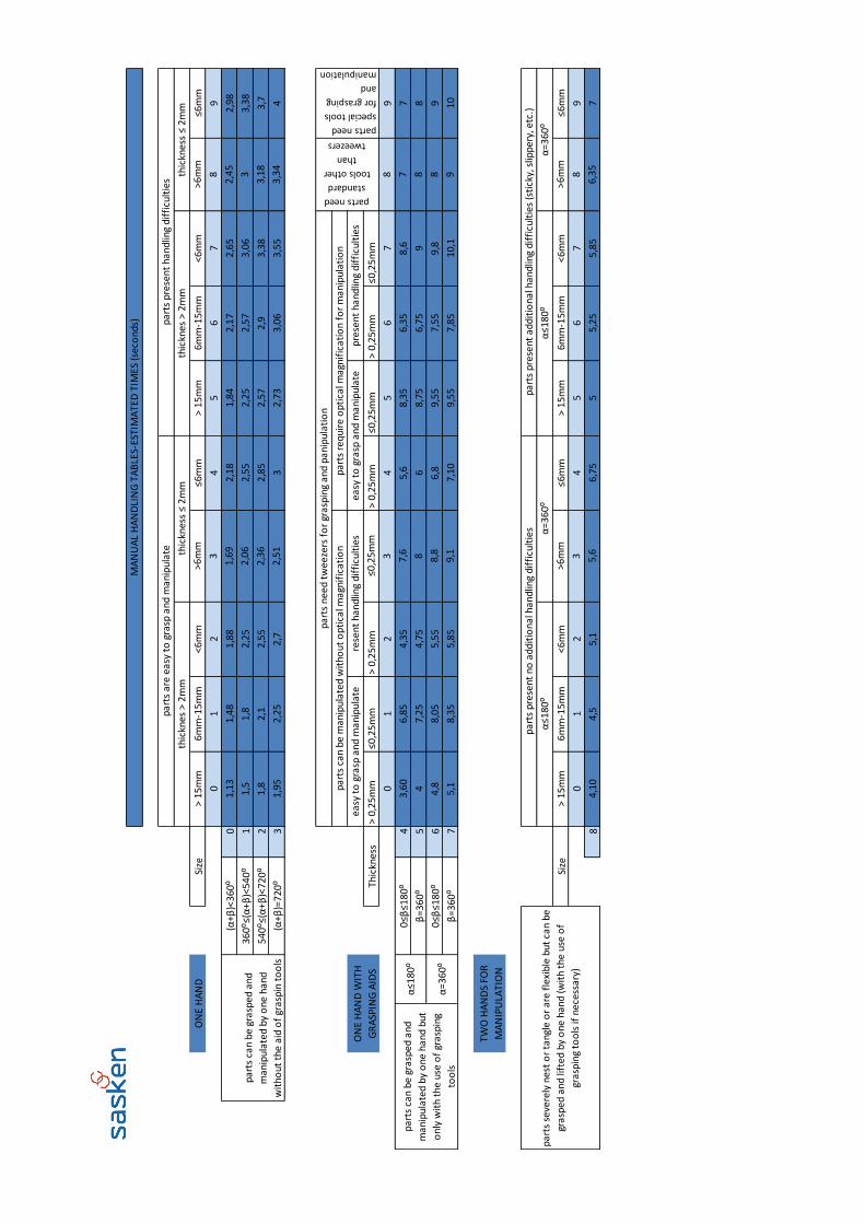
On the analysis page (picture 5) all parts and/or subassemblies are listed and
identified with Part ID. Handling code and Handling time are generated from
Manual Handling Worksheet in five steps. The operation cost/second
information is fed into the Analysis worksheet. The Analysis Worksheet counts
the assembly time (n parts), operation cost, total assembly time (TM) and total
operation cost (CM).
PICTURE 5

24
In the first step you need to pick up an option which describes best assembled
part. (picture 6).
PICTURE 6
25
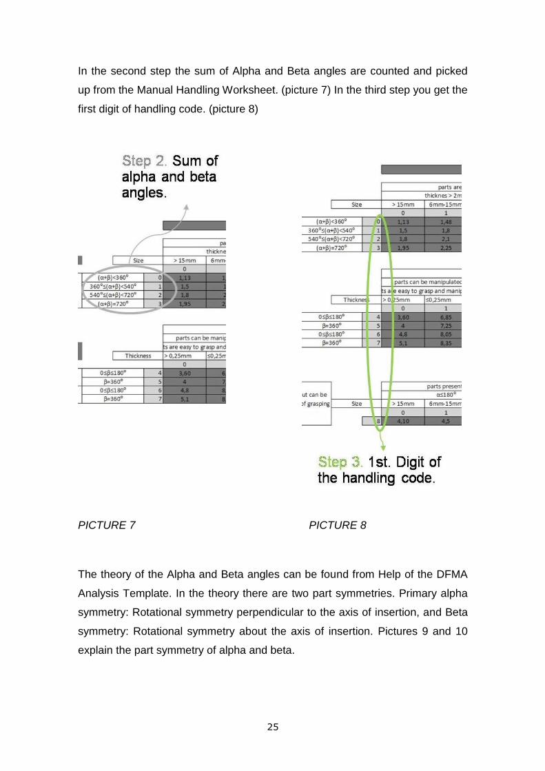
In the second step the sum of Alpha and Beta angles are counted and picked
up from the Manual Handling Worksheet. (picture 7) In the third step you get the
first digit of handling code. (picture 8)
PICTURE 7 PICTURE 8
The theory of the Alpha and Beta angles can be found from Help of the DFMA
Analysis Template. In the theory there are two part symmetries. Primary alpha
symmetry: Rotational symmetry perpendicular to the axis of insertion, and Beta
symmetry: Rotational symmetry about the axis of insertion. Pictures 9 and 10
explain the part symmetry of alpha and beta.

26
PICTURE 9
http://www.scribd.com/doc/4355719/Lecture-5-DFA-Boothro
PICTURE 10
http://www.scribd.com/doc/4355719/Lecture-5-DFA-Boothro

27
In the fourth step you pick up an option that describes the best assembled part.
(picture 11)
PICTURE 11

28
In the fifth step you get the second digit of the handling code. (picture 12)
PICTURE 12

29
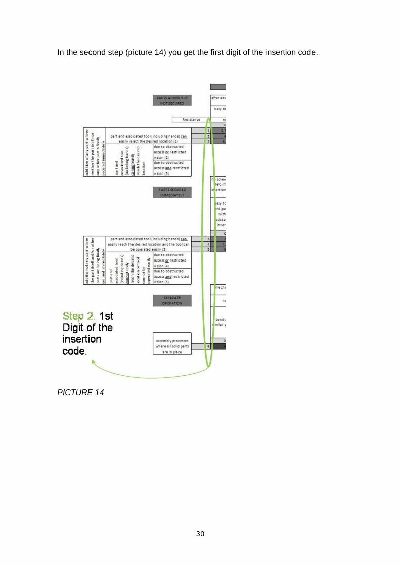
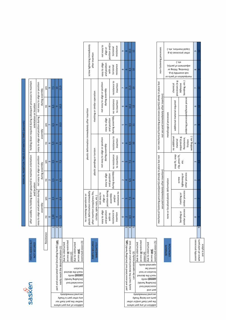
Insertion code and insertion time are generated from Manual Insertion
Worksheet in four steps. In the first step (picture 13) you need to pick up the
option which describes the best assembled part.
PICTURE 13
30
In the second step (picture 14) you get the first digit of the insertion code.
PICTURE 14

31
In the third step (picture 15) you need to pick the option which best describes
the assembled part.
PICTURE 15
In the fourth step (picture 16) you get the second digit of the insertion code.
PICTURE 16
Now you have the first and the second digits of the handling code and the first
and the second digits of the insertion code, you can get the estimated
theoretical handling and insertion times for the part or assembly. Now you need
to insert these times in DFMA Analysis worksheet (picture 5). Next you need to
get operation cost cent/second information. This information can be provided by
the sourcing organization. With this information you can actually convert the
design change proposals into Euros. The theoretical number of the minimum of
parts is a theory which handles the single part or subassembly by three

32
questions. If any of these three questions is answered “yes”, you should keep
the parts independent, separated parts. If all the questions are answered “no”,
you should combine the parts with the others (picture 17). The engineering
solution of course in real life is not this straight and simple. We need to keep in
mind that this is a theoretical and very simplified solution to minimize the
number of parts. In real life you need to compromise.
1. Does the part have to be moved in relation to the rest of the assembly?
2. Must the part be made of a different material from the rest of the assembly for
fundamentally physical reasons?
3. Does the part have to be separated from the assembly for assembly access,
replacement or repair?
PICTURE 17
http://www.scribd.com/doc/4355719/Lecture-5-DFA-Boothro

33
3.4 DFMA Lecture
One of the outcomes of this research was to have a lecture for our mechanical
engineers about DFMA issues. I also had to introduce the DFMA Guideline for
mechanics document, DFMA checklists and DFMA Analysis documents and
how DFM issues are joined in our PD process. I created the lecture material
(appendix 4), arranged and gave the lecture to our engineers. With the same
content I had a second round of interviews to track how the DFMA knowledge
was increased during the process and how the engineers thought about the
outcomes of this research. At the same time I introduced my Master Thesis to
our mechanical engineers.
34
4 CONCLUSION
This research and development was done under our company’s HW capability
& resource development. At the very beginning of this research one of the main
objectives was to create a DFMA process, required by one of our main
customers. They were developing their own DFM capabilities and competencies
and were also setting requirements for suppliers. The customer was especially
interested in the question: At what level our DFM competences were, and
whether we had systematic processes and tools to implement the DFM theory
in design work.
The outcomes of this thesis with Sasken Finland are as follows:
Got understanding of the level of DFMA capabilities and competencies among
mechanics engineers
Improved the knowledge level of DFMA issues among mechanics engineers
Found out and introduced a way of joining the DFMA process part of the PD
process
Developed guidelines, checklists, etc. tools to ease the DFMA design work and
documentation for mechanics engineers
Arranged an internal DFMA course to mechanics engineers, containing use of
documents that were created during this development process and how to join
DFM issues in our PD process
35
5 CONTEMPLATION
I can say that in the organization there was an actual need for the subject of this
master’s thesis. This fact gave me motivation to carry out the thesis work to the
very end. The thesis work was done in schedule, but I have to admit that
completing the master’s report took more time than I had expected. I think that
the outcomes match what is defined at the beginning of this thesis work. Yet
there are some things which I think should be further developed. For example,
the DFMA Analyze template should be transformed into a more usable format,
for example, with a more interactive web based tool. I also think that Design
check lists should be created more, for example, based on different kinds of
production technologies.
I got feedback from the mechanics team mainly after the internal course and it
was mainly positive. The engineers felt that this kind of tools would help them in
their design work especially at the beginning of their career. With this kind of
tools DFMA work is systematic, proven and documented it is not like it was
before.

36
REFERENCES
(1). Boothroyd and Dewhurst, DFM methods 1983
(2). Dr. David M. Andersons, Design for Manufacturability & Concurrent
Engineering, 2008
(3). http://www.scribd.com/doc/4355719/Lecture-5-DFA-Boothro
(4). http://www.sasken.fi/company_profile.htm 27 Oct. 2009

37
APPENDIXES
1. Interview Check List
2. DFMA Guideline for Mechanics
3. DFMA Analysis Template
4. DFMA Analysis Lecture

APPENDIX 1 Interview Check List
Interview Check List
Interviewee: [Name]
Date: [Date]
1st Interview, Survey
Issue Comment
What is DFM/A?
Good example of DFM/A?
Bad example of DFM/A?
Consequence of good DFM/A?
Consequence of bad DFM/A?
Who takes care of the DFM/A?
How DFM/A shows in our PD process?
Who is responsible that DFM/A issues are taken care of?
At which state of the PD process DFM/A issues should be considered?
Where can you get information/support in DFM/A issues?
How well do you think DFM/A issues are taken care of in our company?
Do you think the company should do some corrections?
Do you think you should do something different?
Date: [Date]
2nd Interview, Follow-Up
Issue Comment
What is DFM/A?
Good example of DFM/A?
Bad example of DFM/A?
Consequence of good DFM/A?
Consequence of bad DFM/A?
Who takes care of the DFM/A?
How DFM/A shows in our PD process?
Who is responsible that DFM/A issues are taken care of?
At which state of the PD process DFM/A issues should be considered?
Where can you get information/support in DFM/A issues?
How well do you think DFM/A issues are taken care of in our company?
Do you think the company should do some corrections?
Do you think you should do something different?

APPENDIX 2 DFMA Guideline for Mechanics
15 April 2009
DFMA Guideline for Mechanics
DFMA Process Development
Ilpo Mettovaara
DFMA Guideline for Mechanics

APPENDIX 2 DFMA Guideline for Mechanics
15 April 2009
DFMA Guideline for Mechanics
DFMA Process Development
Ilpo Mettovaara
Change History:
Version State Date Author Description
0.1 Draft 28.04.2009 Mikko Keskilammi Reviewed
0.2 Draft 12.05.2009 Mikko Keskilammi Reviewed
0.3 Draft 19.08.2009 Mikko Keskilammi Reviewed
0.4 Draft 15.10.2009 Mikko Keskilammi Reviewed
1.0 19.11.2010 Ilpo Mettovaara

15 April 2009
DFMA Guideline for Mechanics
DFMA Process Development
Ilpo Mettovaara
Copyright © 2010 Sasken Finland Oy Ilpo Mettovaara 08.12.2010
CONTENTS 1 Purpose of this document ............................................................................ 4
1.1 DFM/DFA ............................................................................................. 4
1.2 Key DFM/A Principles ............................................................................ 4
1.3 What DFM/A is not ................................................................................ 5 2 Generic Guidelines ..................................................................................... 5
2.1 Simplify the design and reduce the number of parts ................................. 5
2.2 Standardize and use common parts and materials .................................... 6
2.3 Design for ease of fabrication ................................................................. 6
2.4 Design within process capabilities and avoid unneeded surface finish
requirements ...................................................................................... 6
2.5 Design Mistake-proof product design and assembly (poka-yoke) ................ 7
2.6 Design for part orientation and handling .................................................. 7
2.7 Minimize flexible parts and interconnections ............................................ 8
2.8 Design for ease of assembly .................................................................. 9
2.9 Design for efficient joining and fastening ................................................. 9
2.10 Design modular products ....................................................................... 9
2.11 Design for automated production .......................................................... 10
2.12 Design printed circuit boards for assembly ............................................. 10 3 DFM/A trough concept/architecture ............................................................ 11
4 DFM/A trough product design, integration & Verification ............................... 11
5 DFM/A trough Type approval & certification ................................................. 12
6 DFM trough Volume production phase ......................................................... 12
7 APPENDIX ..................................................... Error! Bookmark not defined.
8 REFERENCES ........................................................................................... 13

15 April 2009
DFMA Guideline for Mechanics
DFMA Process Development
Ilpo Mettovaara
Copyright © 2010 Sasken Finland Oy Ilpo Mettovaara 08.12.2010
1 Purpose of this document
The purpose of this document is to help Mechanics Engineers during the Product
Development process to design and to optimize the product design for
manufacturability and assembly. The purpose of this document is to act as a short
introduction and guideline in DFMA. In the appendix there are several guidelines
which act as checklists and documentation of DFMA issues during the whole Product
Development process. The final document is part of the Product Development
process documentation. DFMA Analysis template (appendix 3) is used to evaluate,
compare and develop certain assembly or product and collect data for DFMA
metrics.
This document is authored, reviewed and updated every year under HW Recourse
and Capability Management.
1.1 DFM/DFA
Design For Manufacturability/Assembly is the theory or process of proactively
designing product to: a) optimize all the manufacturing functions: fabrication,
assembly test, procurement, shipping, service and repair; b)assure the best cost,
quality, reliability, regulatory compliance, safety, time-to-market, and customer
satisfaction; and c) ensure that lack of manufacturability doesn’t compromise
functionality, styling, new product introductions, product delivery, improvement
programs, strategic initiatives and unexpected surges in product demand.
1.2 Key DFM/A Principles
Do it right first time; you can’t afford to do it over. No arbitrary decisions.
It’s everyone’s responsibility to consider all the goals and constraints early.
Don’t throuw it over the wall.
Define the product well to satisfy the “voice of the customer”.
The most important time-to-market measurement is the time to stable,
trouble-free production. No energy and time wasted on firefighting in mass
production phase.
The further into a design, harder it is to start satisfying additional needs. No
late engineering changes.
The most effective way to achieve quality is to design it in and then build it
in.
Cost is designed into the product, especially by early concept decisions, and
is difficult to remove later.
Design to optimize the system, not just many parts that are hard to
integrate together. The team should be designing the product concurrently
as a team.
Break down the walls by working together, in multifunctional design teams,
all members are expected to jointly design the product.
Make sure all the specialties are present to confront all the difficult tradeoffs
and resolve the issues early.

15 April 2009
DFMA Guideline for Mechanics
DFMA Process Development
Ilpo Mettovaara
Copyright © 2010 Sasken Finland Oy Ilpo Mettovaara 08.12.2010
Early Vendor involvement, one of the main strengths of Concurrent
Engineering is early and active participation of vendors. Past relationships
and proven record of performance.
Use proven features and modules from previous designs to avoid reinventing
the wheel. Use standard parts for New Designs. Optimize the Utilization of
Off-the-Shelf Parts. ”Never design a part you can buy out of a catalog”
Use methodical approaches to specifying tolerances for an optimal balance
of performance, cost, quality, and safety.
Work with other projects to design product families to maximize synergies
and avoid duplication of effort.
Proactively manage product variety by designing for lean production, build-
to- order, and mass customization.
1.3 What DFM/A is not
DFM/A is not a late step that, once checked off, gets you trough a design
review or gate
DFM/A is not done by the “DFM/A Engineer”
DFM/A is not done by a “tool”
DFM/A is not just done at the parts level; most opportunities are at the
system level
DFM/A is not an afterthought
DFM/A is not to be “caught” later in design reviews
DFM/A is not to be accomplished by changes
DFM/A is not thrown over the wall to Vendor or production engineers
2 Generic Guidelines
Following list is meant to followed trough during the Product Development process.
Following list is generic and should be used together with part/assembly based
checklists, shown in appendix of this document.
2.1 Simplify the design and reduce the number of
parts
”The best part is the undone part”
Because of each part, there is an opportunity for a defective part an assembly
error. As the number of parts goes up, the total cost of fabricating and assembling
goes up. The designer should go through the assembly part by part and evaluate
whether the part can be eliminated, combined with another part, or the function
can be performed in another way.
15 April 2009
DFMA Guideline for Mechanics
DFMA Process Development
Ilpo Mettovaara
Copyright © 2010 Sasken Finland Oy Ilpo Mettovaara 08.12.2010
2.2 Standardize and use common parts and materials
To facilitate design activities, to minimize the amount of inventory in the system,
and to standardize handling and assembly operations. Operator learning is
simplified and there is a great opportunity for automation. Limit exotic or unique
components, materials or processes. Use similar designs and common material.
2.3 Design for ease of fabrication
Select process compatible with material and production volumes. Avoid
unnecessary part features because they involve extra processing effort and/or more
complex tooling. Apply specific guidelines for the fabrication process. Work closely
together with part supplier as early as possible.
2.4 Design within process capabilities and avoid unneeded surface finish requirements
Know the production process capabilities of equipment and establish controlled
process. Avoid unnecessarily tight tolerances that are beyond the natural capability
of the manufacturing processes. Also avoid tight tolerances on multiple, connected
parts. Design in the center of a components parameter range to improve reliability
and limit the range of variance around the parameter objective. Surface finish
requirements likewise may be established based on standard practices and may be
15 April 2009
DFMA Guideline for Mechanics
DFMA Process Development
Ilpo Mettovaara
Copyright © 2010 Sasken Finland Oy Ilpo Mettovaara 08.12.2010
applied to interior surfaces resulting in additional costs where these requirements
may not be needed.
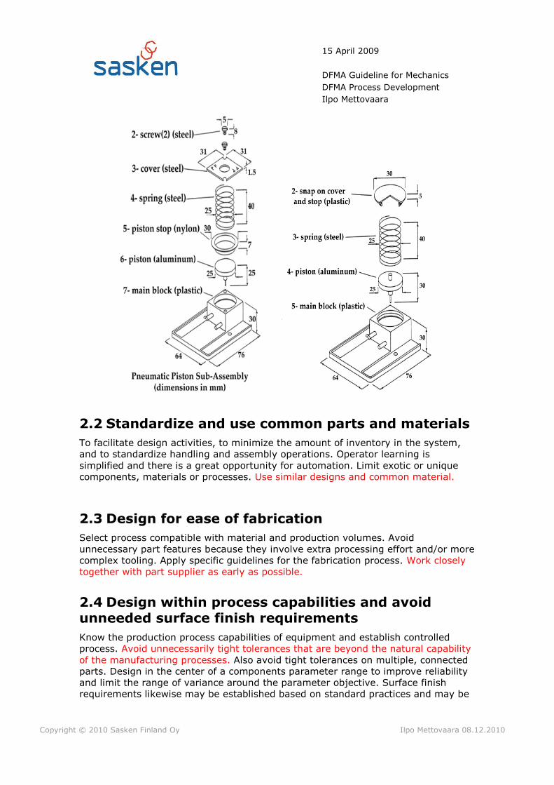
2.5 Design Mistake-proof product design and assembly (poka-yoke)
So that assembly process in unambiguous. Components should be designed so that
they can only be assembled in one way; they cannot be reserved. Notches,
asymmetrical holes and stops can be used to mistake-proof proof the assembly
process. For mechanics products, verifiability can be achieved with simple go/no go
tools. Products should be designed to avoid or simplify adjustment.
2.6 Design for part orientation and handling
To minimize non-value-added manual effort and ambiguity in orienting and merging
parts. Basic principles to facilitate parts handling and orienting are:
Parts must be designed to consistently orient themselves when fed into a
process.
Product design must avoid parts which can become tangled, wedged or
disoriented. Avoid holes and tabs and designed "closed" parts. This type of
design will allow the use of automation in parts handling and assembly such
as vibratory bowls, tubes, magazines, etc.
Part design should incorporate symmetry around both axes of insertion
wherever possible. Where parts cannot be symmetrical, the asymmetry
should be emphasized to assure correct insertion or easily identifiable
feature should be provided.
With hidden features that require a particular orientation, provide an
external feature or guide surface to correctly orient the part.
Guide surfaces should be provided to facilitate insertion.
Parts should be designed with surfaces so that they can be easily grasped,
placed and fixed. Ideally this means flat, parallel surfaces that would allow a

15 April 2009
DFMA Guideline for Mechanics
DFMA Process Development
Ilpo Mettovaara
Copyright © 2010 Sasken Finland Oy Ilpo Mettovaara 08.12.2010
part to picked-up by a person or a gripper with a pick and place robot and
then easily fixed.
Minimize thin, flat parts that are more difficult to pick up. Avoid very small
parts that are difficult to pick-up or require a tool such as a tweezers to
pick-up. This will increase handling and orientation time.
Avoid parts with sharp edges, burrs or points. These parts can injure
workers or customers, they require more careful handling, they can damage
product finishes, and they may be more susceptible to damage themselves if
the sharp edge is an intended feature.
Avoid parts that can be easily damaged or broken.
Avoid parts that are sticky or slippery (thin oily plates, oily parts, adhesive
backed parts, small plastic parts with smooth surfaces, etc.).
Avoid heavy parts that will increase worker fatigue, increase risk of worker
injury, and slow the assembly process.
Design the work station area to minimize the distance to access and move a
part.
2.7 Minimize flexible parts and interconnections
Avoid flexible and flimsy parts such as belts, gaskets, tubing, cables and wire
harnesses. Their flexibility makes material handling and assembly more difficult and
these parts are more susceptible to damage.
15 April 2009
DFMA Guideline for Mechanics
DFMA Process Development
Ilpo Mettovaara
Copyright © 2010 Sasken Finland Oy Ilpo Mettovaara 08.12.2010
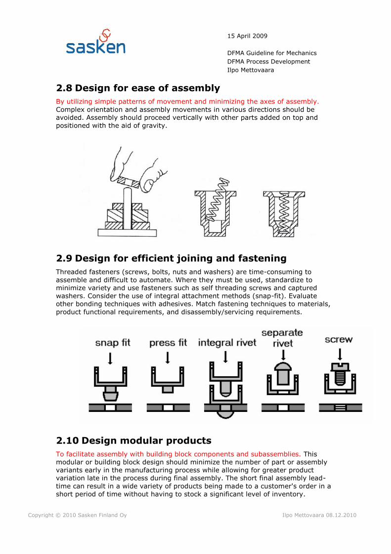
2.8 Design for ease of assembly
By utilizing simple patterns of movement and minimizing the axes of assembly.
Complex orientation and assembly movements in various directions should be
avoided. Assembly should proceed vertically with other parts added on top and
positioned with the aid of gravity.
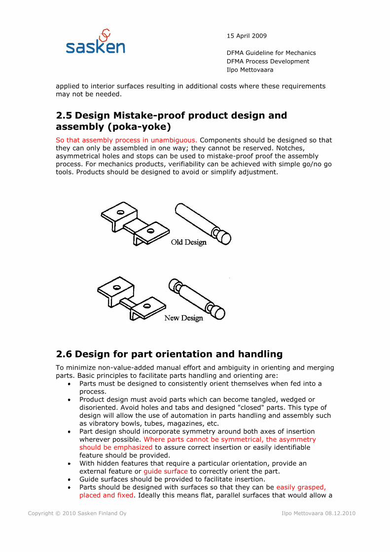
2.9 Design for efficient joining and fastening
Threaded fasteners (screws, bolts, nuts and washers) are time-consuming to
assemble and difficult to automate. Where they must be used, standardize to
minimize variety and use fasteners such as self threading screws and captured
washers. Consider the use of integral attachment methods (snap-fit). Evaluate
other bonding techniques with adhesives. Match fastening techniques to materials,
product functional requirements, and disassembly/servicing requirements.
2.10 Design modular products
To facilitate assembly with building block components and subassemblies. This
modular or building block design should minimize the number of part or assembly
variants early in the manufacturing process while allowing for greater product
variation late in the process during final assembly. The short final assembly lead-
time can result in a wide variety of products being made to a customer's order in a
short period of time without having to stock a significant level of inventory.

15 April 2009
DFMA Guideline for Mechanics
DFMA Process Development
Ilpo Mettovaara
Copyright © 2010 Sasken Finland Oy Ilpo Mettovaara 08.12.2010
Production of standard modules can be leveled and repetitive schedules
established.
2.11 Design for automated production
Automated production involves less flexibility than manual production. The product
must be designed in a way that can be handled with automation.
2.12 Design printed circuit boards for assembly
Design together with HW designer and PWB lay out designer the coming interfaces
between mechanics and PWB.

15 April 2009
DFMA Guideline for Mechanics
DFMA Process Development
Ilpo Mettovaara
Copyright © 2010 Sasken Finland Oy Ilpo Mettovaara 08.12.2010
3 DFM/A through concept/architecture
Voice of the customer captured and documented
Lessons learned from previous projects understood with respect to
manufacturability, quality and so forth
Concept simplification at the product/process level
Architecture optimization for product, product families, processes and supply
chain
All issues raised and resolved early
Optimal utilization of off-the-shelf parts
Modular strategy determined early
Outsourcing/integration strategy optimizes concurrent engineering,
manufacturability, cost, quality, and responsiveness
Strategy is determined for variety, options, customizations, extensions, and
derivatives
DFMA Analysis done and documented
4 DFM/A through product design, integration
& Verification
DFMA Analysis, if not done yet
The product is designed as a system, not just a collection of parts
Vendors are on the team early to help design parts for their processes
Products are designed for existing processes or concurrently designed new
processes
DFM guidelines are obeyed for all relevant processes
Quality and reliability targets are achieved by design
Mistake proofing by design
Robust design ensures optimal tolerances and compatibility with process
capabilities
Arbitrary decisions are avoided by early participation of complete teams and
early inclusion of all design considerations
Standard parts lists are determined and used for new designs
Parts are selected for quality, availability, and supply chain management
optimization
Cost is computed by total cost measurements
Time is measured to stable, trouble-free production
Documentation is complete and unambiguous

15 April 2009
DFMA Guideline for Mechanics
DFMA Process Development
Ilpo Mettovaara
Copyright © 2010 Sasken Finland Oy Ilpo Mettovaara 08.12.2010
5 DFM/A through Type approval & certification
Assembly and testing of the construction is analyzed
Actual assembly times of each part or assembly is compared with target
values
Unidentified problems are mapped and improvements in construction details
are made.
6 DFM through Volume production phase
Follow-up and reporting of DFM metrics, MFR and assembly and testing
process improvement
Reviewing and finalizing DFM documentation
Identifying improvements in construction design, manufacturing, assembly
or testing processes.
Creating DFM part of Project’s Lessons Learned Report
15 April 2009
DFMA Guideline for Mechanics
DFMA Process Development
Ilpo Mettovaara
Copyright © 2010 Sasken Finland Oy Ilpo Mettovaara 08.12.2010
7 APPENDIXES
|1| Document name: Assembly Check List
Storage:
Author: Ilpo Mettovaara
|2| Document name: Part Design Check List
Storage:
Author: Ilpo Mettovaara
|3| Document name: DFMA Analysis template
Storage:
Author: Ilpo Mettovaara
8 REFERENCES
1. Dr. David M. Andersons, Design for Manufacturability & Concurrent
Engineering, 2008
2. http://www.scribd.com/doc/4355719/Lecture-5-DFA-Boothro
APPENDIX 1 Assembly Check List
DFM/A Guideline for Mechanics Appendix 1
ASSEMBLY CHECK LIST
Responsible Designer: [Name]
Assembly: [Assembly]
Item Code: [Item code]
Project no: [Project no]
Check list
Check point Comment Notes
Understand manufacturing problems/issues of
current/past/related products
Eliminate unnecessary parts
Combine parts
Reduce different kind of parts
Reduce & eliminate fasteners
Design for easy processing, and assembly
Design for Top/Down layered assembly
Enhance self-locating and & alignment capability
Eliminate over constrains to minimize tolerance demands
Provide unobstructed access for parts and tools
Make parts independently replaceable
Order assembly so that the most reliable goes in first; the most
likely to fail goes in last
Make sure options can be added easily
Ensure the products life can be extended with future upgrades
Structure the product into modules and subassemblies, as
appropriate

Make sure the wrong part cannot go in the intended position
Make sure the part cannot go in the wrong position
Design so that parts cannot be installed in the wrong orientation
Revisions to the product design are clearly conveyed to
manufacturing and implemented
Design so that omissions cannot happen
Design so that subsequent part installation will sense previous
part omission
Design so that omissions would be visually obvious
Design so that omissions would be easy to see during inspection
Eliminate process steps that depend on operator's memory
APPENDIX 2 Part Design Check List
DFM/A Guideline for Mechanics Appendix 2
PART DESIGN CHECK LIST
Responsible Designer: [Name]
Assembly: [Assembly Name]
Part: [Part Name]
Item Code: [Item code]
Project no: [Project no]
Check list
Guideline Comment Notes
Understand manufacturing problems/issues of
current/past/related parts
For critical parts, the part designer should be an early and active participant in concept phase
Understand the purpose of the part
First consider off-the-shelf parts. Thoroughly investigate available
candidates
Explore all the ways to design and make the part. Don't just jump at the
first idea that comes to mind
Keep thinking about how the part is to be made throughout the design
process
Design for easy fabrication and processing
Eliminate over constrains to minimize tolerance demands
Obey all the specific guidelines for part design
Design with help of the vendor working with the team
Design the part keeping in mind the optimal balance of design
considerations
Choose raw materials commonly used
Make sure the part cannot go in the wrong position in assembly

Design so that parts cannot be installed in the wrong orientation
Avoid right/left hand parts; use paired parts
Design parts with symmetry
If part symmetry is not possible, make parts very asymmetrical
Design for fixturing; concurrently design fixtures

APPENDIX 3 DFMA Analysis Template Confidential
11 Aug 2009
DFMA Analysis Template
DFMA Process Development
Ilpo Mettovaara
Version State Date Author Description
0.1 Draft 11 Aug.2009 Mikko Keskilammi 1st Draft
0.2 Draft 17 Sept.2009 Mikko Keskilammi Draft, Reviewed
0.3 Draft 12 Oct.2009 Mikko Keskilammi Draft
0.4 Draft 18 Feb. 2010 Mikko Keskilammi Draft
1.0 21.Now.2010 Ilpo Mettovaara
Description:
This DFMA analysis is based on Bootroy's and Dewhurst's DFMA Analyse theory. Theory offers eight rules or guidelines which are important during design of assembly.
1. Reduce part count and variations of parts2. Attempt to eliminate adjustments3. Design self-aligning and self-locating parts
4. Ensure easy access and unrestrivted vision5. Ensure ease of handling parts from bulk, tray etc.
6. Minimize the need of re-orientations during assembly7. Design parts that cannot be installed incorretly8. Maximize part symmetry if possible or make parts obviosly asymmetrical
Instructions:Analysis is done in architecture or concept phase of the PD process. Early before
detailt product design phase begins. Analysis can be done also to redy made product.1. Obtain all the possible information about the product, assembly or part from 3D
models, drawings, samples etc.2. Disassemle the product or assembly, or imagine, and assign an identification number to each items as it is remowed.
3. Begin to reassemble the product begining whit highest identification number and add remaining parts one-by-one.
-Complete one row of the DFMA worksheet for each part-Newer assume that parts are grasped one in each hand and the assembled together before placing them in a partically-completed assembly
4. Do the estimation of theoretical number of parts5. Complete DFMA worksheet , computing total assembly time, cost and design effiency.
6. Go trough the design and try to find ways to improwe design efficiency.7. Complete DFMA worksheet , computing total assembly time, cost and design
effiency for the new assembly.
0
Name
Date DD.MM.YYYY
Action proposals
DFMA Analyze Summary
0,00
0,00
Number of parts
Assembly time
(seconds)
Operatin costs
(cents)
0 0
0
Assembly
Project number / Name
Design efficiency
#DIV/0!Current design
Here you can give written action proposal.
#DIV/0! #DIV/0! #DIV/0!
Proposal
0 0
#DIV/0!
#DIV/0!Change
Change % #DIV/0!
0
0
Convert to
milliminutes

> 15
mm
6m
m-1
5m
m<6
mm
≤6m
m>
15m
m6
mm
-15
mm
<6m
m≤6
mm
01
24
56
79
01
,13
1,4
81
,88
2,1
81
,84
2,1
72
,65
2,9
8
11
,51
,82
,25
2,5
52
,25
2,5
73
,06
3,3
8
21
,82
,12
,55
2,8
52
,57
2,9
3,3
83
,7
31
,95
2,2
52
,73
2,7
33
,06
3,5
54
> 0,
25
mm
≤0,2
5m
m>
0,2
5m
m>
0,2
5m
m≤0
,25
mm
> 0,
25
mm
≤0,2
5m
m
01
24
56
79
43
,60
6,8
54
,35
5,6
8,3
56
,35
8,6
7
54
7,2
54
,75
68
,75
6,7
59
8
64
,88
,05
5,5
56
,89
,55
7,5
59
,89
75
,18
,35
5,8
57
,10
9,5
57
,85
10
,11
0
> 15
mm
6m
m-1
5m
m<6
mm
≤6m
m>
15m
m6
mm
-15
mm
<6m
m≤6
mm
01
24
56
79
84
,10
4,5
5,1
6,7
55
5,2
55
,85
7
ON
E H
AN
D
TW
O H
AN
DS
FOR
MA
NIP
ULA
TIO
N
thic
knes
> 2
mm
pa
rts
are
ea
sy t
o g
rasp
an
d m
an
ipu
late th
ickn
ess
≤ 2m
m
8 8,8
9,1
easy
to
gra
sp a
nd
ma
nip
ula
te
pa
rts
can
be
ma
nip
ula
ted
wit
hou
t o
pti
cal m
agn
ific
ati
on
pa
rts
can
be
gra
sped
an
d
ma
nip
ula
ted
by
on
e ha
nd
bu
t
on
ly w
ith
the
use
of
gra
spin
g
too
ls
thic
knes
> 2
mm
thic
knes
s ≤
2mm
pa
rts
pre
sen
t h
an
dlin
g d
iffi
cult
ies 3,3
4
>6m
m
3
1,6
9
2,0
6
2,3
6
2,5
1
>6m
m
8
2,4
5
3
3,1
8
83 7,6
pre
sen
t h
an
dlin
g d
iffi
cult
ies
≤0,2
5m
m
rese
nt
ha
nd
ling
dif
ficu
ltie
sea
sy t
o g
rasp
an
d m
an
ipu
late
MA
NU
AL
HA
ND
LIN
G T
AB
LES-
EST
IMA
TE
D T
IME
S (s
eco
nd
s)
Size
pa
rts
pre
sen
t n
o a
dd
itio
na
l ha
nd
ling
dif
ficu
ltie
sp
art
s p
rese
nt
ad
dit
ion
al h
an
dlin
g d
iffi
cult
ies
(sti
cky,
slip
per
y, e
tc.)
α≤1
80
⁰α
=36
0⁰
α≤1
80
⁰α
=36
0⁰parts need
special tools
for grasping
and
manipulation
7 8 8 9
pa
rts
nee
d t
wee
zers
fo
r gr
asp
ing
an
d p
an
ipu
lati
on
pa
rts
req
uir
e o
pti
cal m
agn
ific
ati
on
fo
r m
an
ipu
lati
on
parts need
standard
tools other
than
tweezers
>6m
m>6
mm
38
5,6
6,3
5
pa
rts
seve
rely
nes
t o
r ta
ngl
e o
r a
re f
lexi
ble
bu
t ca
n b
e
gra
sped
an
d li
fted
by
on
e ha
nd
(w
ith
the
use
of
gra
spin
g to
ols
if n
eces
sary
)
(α+β
)<3
60
⁰
36
0⁰≤
(α+β
)<5
40
⁰
54
0⁰≤
(α+β
)<7
20
⁰
(α+β
)=7
20
⁰
pa
rts
can
be
gra
sped
an
d
ma
nip
ula
ted
by
on
e ha
nd
wit
hou
t th
e ai
d o
f gr
asp
in t
oo
ls
0≤β
≤18
0⁰
β=
36
0⁰
0≤β
≤18
0⁰
β=
36
0⁰
α≤1
80
⁰
α=3
60
⁰
Size
Th
ickn
ess
ON
E H
AN
D W
ITH
GR
ASP
ING
AID
S
no
yes
no
yes
no
yes
no
yes
01
23
67
89
11
,50
2,5
2,5
3,5
5,5
6,5
6,5
7,5
24
55
68
99
10
35
,56
,56
,57
,59
,51
0,5
10
,51
1,5
01
23
45
67
89
32
54
56
78
96
8
44
,57
,56
,57
,58
,59
,51
0,5
11
,58
,51
0,5
56
98
91
01
11
21
31
01
2
01
23
45
67
89
94
75
3,5
78
12
12
91
2
PA
RTS
AD
DED
BU
T
NO
T SE
CU
RED R
esis
tan
ce
easy
to
alig
n a
nd
po
siti
on
du
rin
g
asse
mb
ly
no
t ea
sy t
o a
lign
or
po
siti
on
du
rin
g as
sem
bly
wel
d/b
raze
pro
cess
sold
erin
g p
roce
ss
no
ad
dit
ion
al
mat
eria
l
req
uir
ed (
e.g.
Res
ista
nce
,
fric
tio
n
wel
din
g, e
tc.)
snap
fit
, sna
p
clip
, pre
ss f
it,
etc.
scre
w
tigh
ten
ing
or
oth
er p
roce
ss
rive
ttin
g o
r
sim
ilar
pro
cess
ben
din
g o
r
sim
ilar
pro
cess
asse
mb
ly p
roce
sses
wh
ere
all s
olid
par
ts
are
in p
lace
PA
RTS
SEC
UR
ED
IMM
EDIA
TELY
easy
to
alig
n
and
po
siti
on
du
rin
g as
sem
bly
no
t ea
sy t
o
alig
n o
r
po
siti
on
du
rin
g
asse
mb
ly
and
/or
resi
stan
ce t
o
inse
rtio
n
easy
to
alig
n
and
po
siti
on
wit
h n
o
resi
stan
ce t
o
inse
rtio
n
MA
NU
AL
INSS
RTI
ON
TA
BLE
S-ES
TIM
ATE
D T
IMES
(se
con
ds)
ho
ldin
g d
ow
n r
equ
ired
du
rin
g su
bse
qu
ent
pro
cess
es t
o m
ain
tain
ori
enta
tio
n o
r lo
cati
on
afte
r as
seb
ly n
o h
old
ing
do
wn
geq
uir
ed t
o m
ain
tain
ori
enta
tio
n
and
loca
tio
n
easy
to
alig
n a
nd
po
siti
on
du
rin
g
asse
mb
ly
no
t ea
sy t
o a
lign
or
po
siti
on
du
rin
g as
sem
bly
addition of any part where
neither the part itself nor
any other part is finally
secured immediately
pla
stic
pen
din
g o
r to
rsio
nri
vett
ing
or
sim
ilar
op
erat
ion
pla
stic
def
orm
atio
n im
med
iate
ly a
fter
inse
rtio
n
par
t an
d a
sso
ciat
ed t
oo
l (in
clu
din
g h
and
s) c
an
easi
ly r
each
the
des
ired
loca
tio
n (
1)
du
e to
ob
stru
cted
acce
ss o
r re
stri
cted
visi
on
(2
)
du
e to
ob
stru
cted
acce
ss a
nd
rest
rict
ed v
isio
n (
3)
part and
associated tool
(including hands)
cannot easily
reach the desired
location
no
scr
ewin
g o
per
atio
ns
or
pla
stic
def
orm
atio
n im
med
iatl
y
afte
r in
sert
ion
(sn
ap/p
ress
fit
s,
circ
lips,
spi
re n
uts
, etc
.)
no
t ea
sy t
o a
lign
or
po
siti
on
du
rin
g as
sem
bly
no
res
ista
nce
to in
sert
ion
resi
stan
ce t
o
inse
rtio
n
scre
w t
igh
ten
ing
imm
edia
tely
afte
r in
sert
ion
easy
to
alig
n
and
po
siti
on
du
rin
g as
sem
bly
no
t ea
sy t
o a
lign
or
po
siti
on
du
rin
g as
sem
bly
no
res
ista
nce
to in
sert
ion
resi
stan
ce t
o
inse
rtio
n
easy
to
alig
n
and
po
siti
on
wit
h n
o
tors
ion
al
resi
stan
ce
no
t ea
sy t
o
alig
n o
r
po
siti
on
an
d/o
r
tors
ion
al
resi
stan
ce
addition of any part where
the part itself and/or other
parts are being finally
secured immediately
par
t an
d a
sso
ciat
ed t
oo
l (in
clu
din
g h
and
s) c
an
easi
ly r
each
the
des
ired
loca
tio
n a
nd
the
to
ol
can
be
op
erat
ed e
asi
ly (
3)
part and
associated tool
(including hands)
cannot easily
reach the desired
location or tool
cannot be
operated easily
du
e to
ob
stru
cted
acce
ss o
r re
stri
cted
visi
on
(4
)
du
e to
ob
stru
cted
acce
ss a
nd
rest
rict
ed v
isio
n (
5)
mec
han
ical
fas
ten
ing
pro
cess
es(p
art(
s) a
lrea
dy
in p
lace
bu
t n
ot
secu
red
imm
edia
tely
aft
er in
sert
ion
)
chem
ical
pro
cess
es (e
.g.
Ad
hes
ive
bo
nd
ing,
etc
.)
manipulation of parts or
sub-assembly (e.g.
Orienting, fitting or
adjustment of part(s),
etc.)
other processes (e.g.
Liquid insertion, etc.)
no
n-f
aste
nin
g p
roce
sses
no
ne
or
loca
lized
pla
stic
def
orm
atio
nm
etal
lurg
ical
pro
cess
es
add
itio
nal
mat
eria
l req
uir
ed
no
n-m
ech
anic
al f
aste
nin
g p
roce
sses
(par
t(s)
alr
edy
in p
lace
bu
t
no
t se
cure
d im
med
iate
ly a
fter
inse
rtio
n)
SEP
AR
ATE
OP
ERA
TIO
N

ESTIMATING THEORETICAL NUMBER OF PARTS
Add a Part
Does the part need to
move relative to the rest of the assembly?
Must the part be made of a different
material from rest of the assembly for fundamentall physical reasons?
Does the part have to be separated from
the assembly for assembly access, replacement or repair?
Combine the two
parts
Add zero to the minimum
theoretical number of partsAdd one to the minimum
theoretical number of parts
Add next part
Keep the two parts
separate
Firs t part theoretican
# of part is 1
NO
NO
NO
YES
YES
YES

APPENDIX 4 DFMA Analysis Lecture


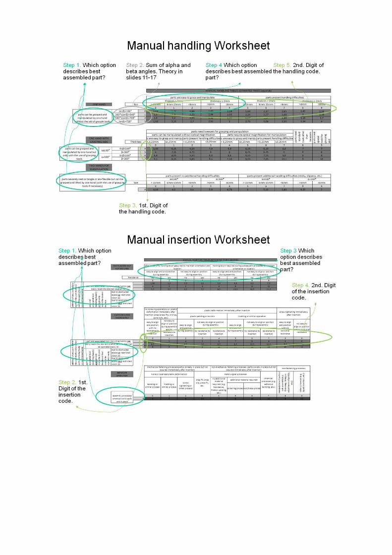


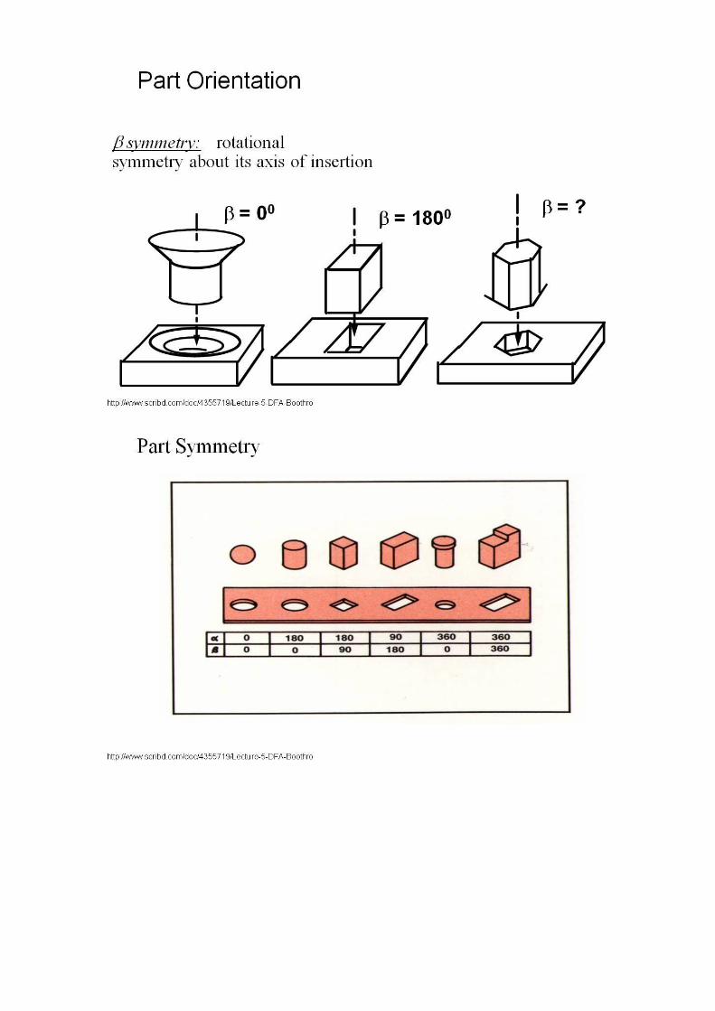
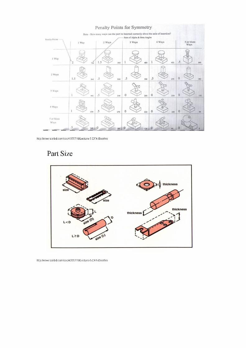


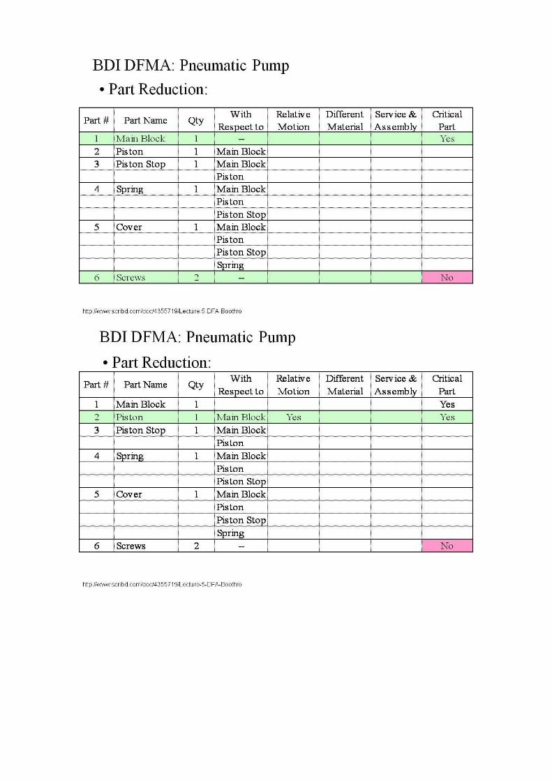


Thumbs.db