l1000a quick start guide - elevator
TRANSCRIPT

1000A AC Elevator Drive Quick Start Guide
Type: CIMR-LU A Models: 200 V Class: 1.5 to 110 kW (2 to 150 HP) 400 V Class: 1.5 to 132 kW (2 to 200 HP) To properly use the product, read this manual thoroughly and retain for easy reference, inspection, and maintenance. Ensure that the end user receives this manual.
TM7349 rev 01 © Magnetek Elevator 2012

2 Magnetek L1000A AC Drive for Elevator Applications Quick Start Guide
Copyright © 2012 MAGNETEK.
All rights reserved. No part of this publication may be reproduced, stored in a retrieval system, or transmitted, in any form, or by any means, mechanical, electronic, photocopying, recording, or otherwise, without the prior written permission of Magnetek. No patent liability is assumed with respect to the use of the information contained herein. Moreover, because Magnetek is constantly striving to improve its high-quality products, the information contained in this manual is subject to change without notice. Every precaution has been taken in the preparation of this manual. Nevertheless, Magnetek assumes no responsibility for errors or omissions. Neither is any liability assumed for damages resulting from the use of the information contained in this publication.

Magnetek L1000A AC Drive for Elevator Applications Quick Start Guide 3
◆ Quick Reference
Drive a Synchronous PM Motor
L1000A can operate synchronous PM motors. Flowchart C: Auto-Tuning for PM Motors on page 59.
Perform Auto-TuningAutomatic tuning sets motor parameters. Refer to Types of Auto-Tuning on page 61.
Maintenance Check Using Drive MonitorsUse drive monitors to check fans, capacitors, and other components may require maintenance. Refer to Performance Life Monitors Maintenance Monitors on page 123.
Fault Display and TroubleshootingRefer to Troubleshooting on page 110.
Standards Compliance
Refer to European Standards on page 188 and UL and CSA Standards on page 195. CSA B44.1 /ASME A17.5

4 Magnetek L1000A AC Drive for Elevator Applications Quick Start Guide
This Page Intentionally Blank

Magnetek L1000A AC Drive for Elevator Applications Quick Start Guide 5
Table of ContentsQuick Reference . . . . . . . . . . . . . . . . . . . . . . . . . . . . . . . . . . . . . . . . . . . . . . . . . . . . . . .3
i. Preface & General Safety ................................................................................................. 7Preface . . . . . . . . . . . . . . . . . . . . . . . . . . . . . . . . . . . . . . . . . . . . . . . . . . . . . . . . . . . . . .7General Safety. . . . . . . . . . . . . . . . . . . . . . . . . . . . . . . . . . . . . . . . . . . . . . . . . . . . . . . . .7
1. Receiving ......................................................................................................................... 15Model Number and Nameplate Check . . . . . . . . . . . . . . . . . . . . . . . . . . . . . . . . . . . . .15
2. Mechanical Installation................................................................................................... 17Mechanical Installation . . . . . . . . . . . . . . . . . . . . . . . . . . . . . . . . . . . . . . . . . . . . . . . . .17
3. Electrical Installation ...................................................................................................... 21Standard Connection Diagram . . . . . . . . . . . . . . . . . . . . . . . . . . . . . . . . . . . . . . . . . . .21Main Circuit Connection Diagram . . . . . . . . . . . . . . . . . . . . . . . . . . . . . . . . . . . . . . . . .24Terminal Cover . . . . . . . . . . . . . . . . . . . . . . . . . . . . . . . . . . . . . . . . . . . . . . . . . . . . . . .25Digital Operator and Front Cover . . . . . . . . . . . . . . . . . . . . . . . . . . . . . . . . . . . . . . . . .27Main Circuit Wiring . . . . . . . . . . . . . . . . . . . . . . . . . . . . . . . . . . . . . . . . . . . . . . . . . . . .29Control I/O Configuration. . . . . . . . . . . . . . . . . . . . . . . . . . . . . . . . . . . . . . . . . . . . . . . .44Connect to a PC . . . . . . . . . . . . . . . . . . . . . . . . . . . . . . . . . . . . . . . . . . . . . . . . . . . . . .45Wiring Checklist. . . . . . . . . . . . . . . . . . . . . . . . . . . . . . . . . . . . . . . . . . . . . . . . . . . . . . .46
4. Start-Up Programming & Operation ............................................................................. 47Using the Digital Operator . . . . . . . . . . . . . . . . . . . . . . . . . . . . . . . . . . . . . . . . . . . . . . .47The Drive and Programming Modes . . . . . . . . . . . . . . . . . . . . . . . . . . . . . . . . . . . . . . .52Start-Up Flowcharts. . . . . . . . . . . . . . . . . . . . . . . . . . . . . . . . . . . . . . . . . . . . . . . . . . . .54Setup Procedure for Elevator Applications . . . . . . . . . . . . . . . . . . . . . . . . . . . . . . . . . .69S: Elevator Parameters . . . . . . . . . . . . . . . . . . . . . . . . . . . . . . . . . . . . . . . . . . . . . . . . .78Setup Troubleshooting and Possible Solutions . . . . . . . . . . . . . . . . . . . . . . . . . . . . . .107
5. Troubleshooting............................................................................................................ 110Fault Detection . . . . . . . . . . . . . . . . . . . . . . . . . . . . . . . . . . . . . . . . . . . . . . . . . . . . . .110Alarm Detection . . . . . . . . . . . . . . . . . . . . . . . . . . . . . . . . . . . . . . . . . . . . . . . . . . . . . .114Operator Programming Errors . . . . . . . . . . . . . . . . . . . . . . . . . . . . . . . . . . . . . . . . . . .116Auto-Tuning Fault Detection . . . . . . . . . . . . . . . . . . . . . . . . . . . . . . . . . . . . . . . . . . . .117Copy Function Related Displays . . . . . . . . . . . . . . . . . . . . . . . . . . . . . . . . . . . . . . . . .118
6. Periodic Inspection & Maintenance ............................................................................ 120Inspection . . . . . . . . . . . . . . . . . . . . . . . . . . . . . . . . . . . . . . . . . . . . . . . . . . . . . . . . . .120Periodic Maintenance . . . . . . . . . . . . . . . . . . . . . . . . . . . . . . . . . . . . . . . . . . . . . . . . .122Drive Replacement . . . . . . . . . . . . . . . . . . . . . . . . . . . . . . . . . . . . . . . . . . . . . . . . . . .124
7. Option Card Installation ............................................................................................... 127Prior to Installing the Option . . . . . . . . . . . . . . . . . . . . . . . . . . . . . . . . . . . . . . . . . . . .127Installing the Option. . . . . . . . . . . . . . . . . . . . . . . . . . . . . . . . . . . . . . . . . . . . . . . . . . .128Wire Gauges, Tightening Torque, and Crimp Terminals . . . . . . . . . . . . . . . . . . . . . . .135Terminal Functions of PG-B3 and PG-X3 Option . . . . . . . . . . . . . . . . . . . . . . . . . . . .136
A. Specifications................................................................................................................ 137Three-Phase 200 V Class Drives . . . . . . . . . . . . . . . . . . . . . . . . . . . . . . . . . . . . . . . .137Three-Phase 400 V Class Drives . . . . . . . . . . . . . . . . . . . . . . . . . . . . . . . . . . . . . . . .138

Table of Contents
6 Magnetek L1000A AC Drive for Elevator Applications Quick Start Guide
Drive Specifications . . . . . . . . . . . . . . . . . . . . . . . . . . . . . . . . . . . . . . . . . . . . . . . . . . .139B. Parameter Table ............................................................................................................ 141
A: Initialization Parameters . . . . . . . . . . . . . . . . . . . . . . . . . . . . . . . . . . . . . . . . . . . . .141b: Application . . . . . . . . . . . . . . . . . . . . . . . . . . . . . . . . . . . . . . . . . . . . . . . . . . . . . . . .142C: Tuning . . . . . . . . . . . . . . . . . . . . . . . . . . . . . . . . . . . . . . . . . . . . . . . . . . . . . . . . . . .144d: Speed References. . . . . . . . . . . . . . . . . . . . . . . . . . . . . . . . . . . . . . . . . . . . . . . . . .148E: Motor Parameters . . . . . . . . . . . . . . . . . . . . . . . . . . . . . . . . . . . . . . . . . . . . . . . . . .150F: Option Settings . . . . . . . . . . . . . . . . . . . . . . . . . . . . . . . . . . . . . . . . . . . . . . . . . . . .154H: Multi-Function Terminals. . . . . . . . . . . . . . . . . . . . . . . . . . . . . . . . . . . . . . . . . . . . .158L: Protection Functions . . . . . . . . . . . . . . . . . . . . . . . . . . . . . . . . . . . . . . . . . . . . . . . .164n: Advanced Performance Set-Up. . . . . . . . . . . . . . . . . . . . . . . . . . . . . . . . . . . . . . . .168o: Operator Related Parameters . . . . . . . . . . . . . . . . . . . . . . . . . . . . . . . . . . . . . . . . .170S: Elevator Parameters . . . . . . . . . . . . . . . . . . . . . . . . . . . . . . . . . . . . . . . . . . . . . . . .173T: Motor Tuning . . . . . . . . . . . . . . . . . . . . . . . . . . . . . . . . . . . . . . . . . . . . . . . . . . . . . .177U: Monitors . . . . . . . . . . . . . . . . . . . . . . . . . . . . . . . . . . . . . . . . . . . . . . . . . . . . . . . . .179Defaults and Setting Ranges by Display Unit Selection (o1-03) . . . . . . . . . . . . . . . . .187
C. Standards Compliance ................................................................................................. 188European Standards . . . . . . . . . . . . . . . . . . . . . . . . . . . . . . . . . . . . . . . . . . . . . . . . . .188UL and CSA Standards . . . . . . . . . . . . . . . . . . . . . . . . . . . . . . . . . . . . . . . . . . . . . . . .195Safe Disable Input Function . . . . . . . . . . . . . . . . . . . . . . . . . . . . . . . . . . . . . . . . . . . .204EN81-1 Conform Circuit with one Motor Contactor . . . . . . . . . . . . . . . . . . . . . . . . . . .207
Revision History..............................................................................................................208

i Preface & General Safety
MAGNETEK L1000A AC Drive for Elevator Applications Quick Start Guide 7
i Preface & General Safety
◆ Preface
Magnetek manufactures products used as components in a wide variety of industrial systems and equipment. The selection and application of Magnetek products remain the responsibility of the equipment manufacturer or end user. Magnetek accepts no responsibility for the way its products are incorporated into the final system design. Under no circumstances should any Magnetek product be incorporated into any product or design as the exclusive or sole safety control. Without exception, all controls should be designed to detect faults dynamically and fail safely under all circumstances. All systems or equipment designed to incorporate a product manufactured by Magnetek must be supplied to the end user with appropriate warnings and instructions as to the safe use and operation of that part. Any warnings provided by Magnetek must be promptly provided to the end user. Magnetek offers an express warranty only as to the quality of its products in conforming to standards and specifications published in the Magnetek manual. NO OTHER WARRANTY, EXPRESS OR IMPLIED, IS OFFERED. Magnetek assumes no liability for any personal injury, property damage, losses, or claims arising from misapplication of its products.
This manual is designed to ensure correct and suitable application of L1000A-Series Drives. Read this manual before attempting to install, operate, maintain, or inspect a drive and keep it in a safe, convenient location for future reference. Be sure you understand all precautions and safety information before attempting application.
■ Applicable Documentation
The following manuals are available for L1000A series drives:
◆ General Safety
■ Supplemental Safety Information
L1000A Series AC Drive Quick Start Guide (this book)Read this manual first. This guide is packaged together with the product. It contains basic information required to install and wire the drive, in addition to an overview of fault diagnostics, maintenance, and parameter settings. Use the information in this book to prepare the drive for a trial run with the application and for basic operation.L1000A Series AC Drive Technical Manual This manual provides detailed information on parameter settings, drive functions, and MEMOBUS/Modbus specifications. Use this manual to expand drive functionality and to take advantage of higher performance features.
General Precautions• The diagrams in this manual may be indicated without covers or safety shields to show details. Replace the covers or shields before operating the
drive and run the drive according to the instructions described in this manual.• Any illustrations, photographs, or examples used in this manual are provided as examples only and may not apply to all products to which this
manual is applicable.• The products and specifications described in this manual or the content and presentation of the manual may be changed without notice to
improve the product and/or the manual.• When ordering a new copy of the manual due to damage or loss, contact your Magnetek representative or the nearest Magnetek sales office and
provide the manual number shown on the front cover.• If nameplate becomes worn or damaged, order a replacement from your Magnetek representative or the nearest Magnetek sales office.
W ARNING Read and understand this manual before installing, operating or servicing this drive. The drive must be installed according to this manual and local codes.The following conventions are used to indicate safety messages in this manual. Failure to heed these messages could result in serious or fatal injury or damage to the products or to related equipment and systems.
CIMR-AA2A0021FAA200V 3Phase 5.5kW/3.7kWS/N:
危 険据え付け、運転の前には必ず取扱説明書を読むこと。通電中および電源遮断後5分以内はフロントカバーを外さない事。400V級インバータの場合は、電源の中性点が接地されていることを確認すること。( 対応)保守・点検、配線を行う場合は、出力側開閉器を遮断後5分待って実施してください。
けが.感電のおそれがあります。
高温注意インバータ上部、両側面は高温になります。触らないでください。
●
●
●
●
●
AVERTISSMENT NPJT31470-1
Lire le manuel avant l'installation.Attendre 5 minutes après la coupurede l'alimentation, pour permettrela décharge des condensateurs. Pour répondre aux exigences , sassurer que le neutre soit relié à la terre, pour la série 400V.Après avoir déconnécte la protectionentre le driver et le moteur, veuillezpatienter 5 minutes avain d’effectuerune opération de montage ou decâblage du variateur.
Risque de décharge électrique.
Surfaces ChaudesDessus et cotés du boitier Peuventdevenir chaud. Ne Pas toucher.
WARNINGRead manual before installing.Wait 5 minutes for capacitordischarge after disconnectingpower supply.To conform to requirements,make sure to ground the supplyneutral for 400V class.After opening the manual switchbetween the drive and motor,please wait 5 minutes beforeinspecting, performingmaintenance or wiring the drive.
Risk of electric shock.
Hot surfaces Top and Side surfaces maybecome hot. Do not touch.
●
●
●
●
●
●
●
●
●
●
●
●
●
●
●
LORE
F2F1
ESC
RUN STOP
ENTERRESET
ALMDIGITAL OPERATOR JVOP-180

i Preface & General Safety
8 MAGNETEK L1000A AC Drive for Elevator Applications Quick Start Guide
WARNING! may also be indicated by a bold key word embedded in the text followed by an italicized safety message.
CAUTION! may also be indicated by a bold key word embedded in the text followed by an italicized safety message.
NOTICE: may also be indicated by a bold key word embedded in the text followed by an italicized safety message.
■ Safety Messages
DANGER Indicates a hazardous situation, which, if not avoided, will result in death or serious injury.
W ARNING Indicates a hazardous situation, which, if not avoided, could result in death or serious injury.
CAUTION Indicates a hazardous situation, which, if not avoided, could result in minor or moderate injury.
NOTICE
Indicates a property damage message.
DANGER Heed the safety messages in this manual.Failure to comply will result in death or serious injury.The operating company is responsible for any injuries or equipment damage resulting from failure to heed the warnings in this manual.
Electrical Shock HazardDo not connect or disconnect wiring or service the drive while the power is on.Failure to comply will result in death or serious injury.Before servicing, disconnect all power to the equipment. The internal capacitor remains charged even after the power supply is turned off. After shutting off the power, wait for at least the amount of time specified on the drive before touching any components.
W ARNING Sudden Movement Hazard
The drive system or elevator may start unexpectedly upon application of power, resulting in death or serious injury.• Clear all personnel from the drive, motor, and machine area before applying power. • Secure covers, couplings, shaft keys, and machine loads before applying power to the drive.
Ensure there are no short circuits between the main circuit terminals (R/L1, S/L2, and T/L3) or between the ground and main circuit terminals before restarting the drive.Failure to comply may result in serious injury or death and will cause damage to equipment.

i Preface & General Safety
MAGNETEK L1000A AC Drive for Elevator Applications Quick Start Guide 9
System may start unexpectedly upon application of power when the Auto-restart function is enabled resulting in death or serious injury.Use care when enabling Auto-restart as this function may cause unintended start of the elevator.
Use parameter S1-12 to enable/disable automatic switching of the Motor Contactor Control output signal during Auto-Tuning.When using setting S1-12 = 1, ensure that the multi-function output terminals are properly wired and in the correct state before setting parameter S1-12.Failure to comply could result in damage to the drive, serious injury or death.
Electrical Shock HazardDo not attempt to modify or alter the drive in any way not explained in this manual.Magnetek is not responsible for damage caused by modification of the product made by the user. Failure to comply could result in death or serious injury from operation of damaged equipment.
Do not operate equipment with covers removed.Failure to comply could result in death or serious injury.The diagrams in this section may show drives without covers or safety shields to show details. Be sure to reinstall covers or shields before operating the drives and run the drives according to the instructions described in this manual.
When a drive is running a PM motor, voltage continues to be generated at the motor terminals after the drive is shut off while the motor coasts to stop. Take the precautions described below to prevent shock and injury:• In applications where the machine can still rotate even though the drive has fully stopped a load, install a switch to
the drive output side to disconnect the motor and the drive.• Do not allow an external force to rotate the motor beyond the maximum allowable speed or to rotate the motor when
the drive has been shut off.• Wait for at least the time specified on the warning label after opening the load switch on the output side before
inspecting the drive or performing any maintenance.• Do not open and close the load switch while the motor is running, as this can damage the drive.If the motor is coasting, make sure the power to the drive is turned on and the drive output has completely stopped before closing the load switch.
Do not connect or disconnect wiring to the drive or motor while the power is on.Failure to comply will result in death or serious injury. Before servicing, disconnect all power to the equipment. The internal capacitor remains charged even after the power supply is turned off. The charge indicator LED will extinguish when the DC bus voltage is below 50 Vdc. To prevent electric shock, wait at least five minutes after all indicators are OFF and measure the DC bus voltage level to confirm safe level.
Do not operate equipment with covers removed.Failure to comply could result in death or serious injury.The diagrams in this section may show drives without covers or safety shields to show details. Be sure to reinstall covers or shields before operating the drives and run the drives according to the instructions described in this manual.
Do not perform work on the drive while wearing loose clothing, jewelry or without eye protection.Failure to comply could result in death or serious injury.Remove all metal objects such as watches and rings, secure loose clothing, and wear eye protection before beginning work on the drive.
W ARNING

i Preface & General Safety
10 MAGNETEK L1000A AC Drive for Elevator Applications Quick Start Guide
Do not change wiring, remove covers, connectors or options cards, or attempt to service the drive with power applied to the drive. Failure to comply could result in death or serious injury. Disconnect all power to the drive and check for unsafe voltages before servicing.
Do not allow unqualified personnel to use the equipment.Failure to comply could result in death or serious injury.Maintenance, inspection, and replacement of parts must be performed only by authorized personnel familiar with installation, adjustment and maintenance of AC drives.
Fire HazardDrive Short-Circuit Current RatingInstall adequate branch circuit protection according to applicable local codes and this Installation Manual.Failure to comply could result in fire and damage to the drive or injury to personnel.The device is suitable for use on a circuit capable of delivering not more than 100,000 RMS symmetrical amperes, 240 Vac maximum (200 V class) and 480 Vac maximum (400 V class), and 600 Vac maximum (600 V class) when protected by branch circuit protection devices specified in this manual.
Applications using a braking option should wire a thermal relay so that the output contactor opens when the thermal relay trips.Inadequate braking circuit protection could result in death or serious injury by fire from overheating resistors.
Do not use improper combustible materials.Failure to comply could result in death or serious injury by fire.Attach the drive to metal or other noncombustible material.
NOTICEEquipment Hazard
Do not modify the drive circuitry.Failure to comply could result in damage to the drive and will void warranty.Magnetek is not responsible for any modification of the product made by the user. This product must not be modified.Failure to comply could result in damage to the drive or braking circuit.
Observe proper electrostatic discharge procedures (ESD) when handling the drive, circuit boards, and option cards.Failure to comply may result in ESD damage to the drive circuitry.
Do not operate damaged equipment.Failure to comply could result in further damage to the equipment.Do not connect or operate any equipment with visible damage or missing parts.
Do not lift the drive up while the cover is removed.This can damage the terminal board and other components.
Do not expose the drive to halogen group disinfectants.Failure to comply may cause damage to the electrical components in the drive.Do not pack the drive in wooden materials that have been fumigated or sterilized.Do not sterilize the entire package after the product is packed.
W ARNING

i Preface & General Safety
MAGNETEK L1000A AC Drive for Elevator Applications Quick Start Guide 11
■ General Application PrecautionsMotor SelectionDrive Capacity
The output current should not exceed 150% of the drive rated current. Select a drive that can output enough current when accelerating a load at 100%.
For specialized motors, make sure that the motor rated current is less than the rated output current for the drive.
Starting Torque
The startup and acceleration characteristics of the motor are restricted to the drive's overload current rating (150% rated current for 60 s).
The overload rating for the drive determines the starting and accelerating characteristics of the motor. Expect lower torque than when running from line power. To get more starting torque, use a larger drive or increase both the motor and drive capacity.
StoppingFast Stop
When the drive faults out, a protective circuit is activated and drive output is shut off. This, however, does not stop the motor immediately. A mechanical brake may be required to stop the motor if Fast Stop deceleration is insufficient.
Mechanical Brake
A mechanical brake is required to prevent the elevator from free falling during a drive fault condition.
Repetitive Starting/Stopping
Elevators and other applications with frequent starts and stops often approach 150% of their rated current values. Heat stress generated from repetitive high current will shorten the life span of the IGBTs.
Magnetek recommends lowering the carrier frequency, particularly when audible noise is not a concern. It is beneficial to reduce the load, increase the acceleration and deceleration times, or switch to a larger drive to help keep peak current levels under 150%. Be sure to check the peak current levels when starting and stopping repeatedly during the initial test run, and make adjustments accordingly.
InstallationEnclosure Panels
Keep the drive in a clean environment by installing the drive in an enclosure panel or selecting an installation area free of airborne dust, lint, and oil mist. Be sure to leave the required space between drives to provide for cooling, and take proper measures so the ambient temperature remains within allowable limits and keep flammable materials away from the drive. Magnetek offers protective designs for drives that must be used in areas subjected to oil mist and excessive vibration. Contact Magnetek or your Magnetek representative for details.
Installation Direction
NOTICE: Install the drive upright as specified in the manual. Refer to Mechanical Installation on page 17 for more information on installation. Failure to comply may damage the drive due to improper cooling.
SettingsDC Injection Braking
NOTICE: Excessive current during DC Injection Braking and excessive duration of DC Injection Braking can cause motor overheating. Adjust DC Injection parameters to prevent motor overheating.
Acceleration/Deceleration Ramp
Acceleration and deceleration times are affected by the amount of torque generated by the motor, the load torque, and the inertia moment. Set a longer accel/decel time when Stall Prevention is enabled. The accel/decel times are lengthened for as long as the Stall Prevention function is in operation. Install one of the available braking options or increase the capacity of the drive for faster acceleration and deceleration.

i Preface & General Safety
12 MAGNETEK L1000A AC Drive for Elevator Applications Quick Start Guide
General HandlingSelecting a Molded Case Circuit Breaker or Ground Fault Circuit Interrupter (GFCI)
Select an appropriate GFCI. This drive can cause a residual current with a DC component in the protective earthing conductor. Where a residual current operated protective or monitoring device is used for protection in case of direct or indirect contact, always use an GFCI of type B according to IEC 60755.
Select a MCCB (Molded Case Circuit Breaker) with a rated current that is 1.5 to 2 times higher than the rated current of the drive in order to avoid nuisance trips caused by harmonics in the drive input current.
WARNING! Sudden Movement Hazard. Install a properly controlled contactor on the input-side of the drive for applications where power should be removed from the drive during a fault condition. Improper equipment sequencing could result in death or serious injury.
WARNING! Fire Hazard. Shut off the drive with a magnetic contactor (MC) when a fault occurs in any external equipment such as braking resistors. Failure to comply may cause resistor overheating, fire, and injury to personnel.
NOTICE: To get the full performance life out of the electrolytic capacitors and circuit relays, refrain from switching the drive power supply off and on more than once every 30 minutes. Frequent use can damage the drive. Use the drive to stop and start the motor.
Inspection and Maintenance
WARNING! Electrical Shock Hazard. Capacitors in the drive do not immediately discharge after shutting off the power. Wait for at least the amount of time specified on the drive before touching any components after shutting off the power. Failure to comply may cause injury to personnel from electrical shock.
CAUTION! Burn Hazard. Because the heatsink can get very hot during operation, take proper precautions to prevent burns. When replacing the cooling fan, shut off the power and wait at least 15 minutes to be sure that the heatsink has cooled down. Failure to comply may cause burn injury to personnel.
WARNING! Electrical Shock Hazard. When a drive is running a PM motor, voltage continues to be generated at the motor terminals after the drive is shut off while the motor coasts to stop. Take the precautions described below to prevent shock and injury:
• In applications where the machine can still rotate after the drive has fully stopped a load, install a load disconnect switch on the drive output side to disconnect the motor and the drive.
• Do not allow an external force to rotate the motor beyond the maximum allowable speed or to rotate the motor when the drive is powered off.
• Wait for at least the time specified on the warning label after opening the load switch on the output side before inspecting the drive or performing any maintenance.
• Do not open and close the load switch while the motor is running.• If the motor is coasting, make sure the power to the drive is turned on and the drive output has completely stopped
before closing the load switch to reconnect the drive to the motor.Wiring
Magnetek recommends using ring terminals on all drive models for UL/cUL compliance. Use only the tools recommended by the terminal manufacturer for crimping.
Transporting the Drive
NOTICE: Never steam clean the drive. During transport, keep the drive from coming into contact with salts, fluorine, bromine, phthalate ester, and other such harmful chemicals. Failure to comply may damage the drive.

i Preface & General Safety
MAGNETEK L1000A AC Drive for Elevator Applications Quick Start Guide 13
■ Motor Application PrecautionsStandard Induction MotorsInsulation Tolerance
NOTICE: Consider motor voltage tolerance levels and motor insulation in applications with an input voltage of over 440 V or particularly long wiring distances.
NOTICE: Ensure that the motor is suitable for inverter duty and/or the motor service factor is adequate to accommodate the additional heating with the intended operating conditions. A motor connected to a PWM drive may operate at a higher temperature than a utility-fed motor and the operating speed range may reduce motor cooling capacity.
High-Speed Operation
NOTICE: Mechanical damage may occur with the motor bearings and dynamic balance of the machine when operating a motor beyond its rated speed. Operate the motor within specifications to prevent motor damage.
Low-Speed Range
The cooling fan of a standard motor should sufficiently cool the motor at the rated speed. As the self-cooling capability of such a motor reduces with the speed, applying full torque at low speed will possibly damage the motor. Reduce the load torque as the motor slows to prevent motor damage from overheat. Use a motor designed specifically for operation with a drive when 100% continuous torque is needed at low speeds.
Torque Characteristics
Torque characteristics differ compared to operating the motor directly from line power. The user should have a full understanding of the load torque characteristics for the application.
Vibration and Shock
The drive allows selection of high carrier PWM control and low carrier PWM control. Selecting high carrier PWM can help reduce motor oscillation.
If resonance occurs, install shock-absorbing rubber mounts around the base of the motor and utilize the Jump frequency selection to prevent continuous operation in the resonant frequency ranges.
Audible Noise
Noise created during run varies by the carrier frequency setting. When using a high carrier frequency, audible noise from the motor is comparable to the motor noise generated when running from line power. Operating above the rated r/min, however, can create unpleasant motor noise.
Precautions for PM Motors
NOTICE: Damage to Equipment. Improper sequencing of output motor circuits could result in damage to the drive. Do not connect electromagnetic switches or magnetic contactors to the output motor circuits without proper sequencing. Do not open the main circuit between the drive and the motor while the PM motor is rotating.
• Contact Magnetek or your Magnetek representative if you plan to use any PM motor not endorsed by Magnetek.• When using a holding brake, release the brake prior to starting the motor. Failure to set the proper timing can result in
speed loss.
WARNING! Sudden Movement Hazard. Use the Initial Pole Search Status Signal (H2- = 61) to interlock the brake to ensure the brake is not released before the Initial Magnetic Pole Search is completed. Failure to comply may cause inadvertent elevator movement resulting in serious injury. This safety message is applicable under these conditions:
• When applying a PM motor, with an external brake sequence, and the PG-F3 option is not being used.
WARNING! Electrical Shock Hazard. The motor must be at a complete stop before performing any maintenance, inspection, or wiring.
• With a PM motor, drive output must be fully interrupted when the power is shut off and the motor is still rotating.Failure to comply can result in personal injury from electrical shock.

i Preface & General Safety
14 MAGNETEK L1000A AC Drive for Elevator Applications Quick Start Guide
■ Drive Label Warnings
Always heed the warning information listed in Figure 1 in the position shown in Figure 2.Figure 1
Figure 1 Warning InformationFigure 2
Figure 2 Warning Information Position
■ Warranty InformationRestrictions
The drive is not designed or manufactured for use in devices or systems that may directly affect or threaten human lives or health.
Customers who intend to use the product described in this manual for devices or systems relating to transportation, health care, space aviation, atomic power, electric power, or in underwater applications must first contact their Magnetek representatives or the nearest Magnetek sales office.
WARNING! Injury to Personnel. This product has been manufactured under strict quality-control guidelines. However, if this product is to be installed in any location where failure of this product could involve or result in a life-and-death situation or loss of human life or in a facility where failure may cause a serious accident or physical injury, safety devices must be installed to minimize the likelihood of any accident.
WARNINGRead manual before installing.Wait 5 minutes for capacitordischarge after disconnectingpower supply.To conform to requirements,make sure to ground the supplyneutral for 400V class.After opening the manual switchbetween the drive and motor,please wait 5 minutes beforeinspecting, performingmaintenance or wiring the drive.
Risk of electric shock.
Hot surfaces Top and Side surfaces maybecome hot. Do not touch.
●
●
●
●
●
CIMR200V 3Phase 5.5kW/3.7kWS/N:
危 険据え付け、運転の前には必ず取扱説明書を読むこと。通電中および電源遮断後5分以内はフロントカバーを外さない事。400V級インバータの場合は、電源の中性点が接地されていることを確認すること。( 対応)保守・点検、配線を行う場合は、出力側開閉器を遮断後5分待って実施してください。
けが.感電のおそれがあります。
高温注意インバータ上部、両側面は高温になります。触らないでください。
●
●
●
●
AVERTISSMENT NPJT31470-1
Lire le manuel avant l'installation.Attendre 5 minutes après la coupurede l'alimentation, pour permettrela décharge des condensateurs. Pour répondre aux exigences , sassurer que le neutre soit relié à la terre, pour la série 400V.Après avoir déconnécte la protectionentre le driver et le moteur, veuillezpatienter 5 minutes avain d’effectuerune opération de montage ou decâblage du variateur.
Risque de décharge électrique.
Surfaces ChaudesDessus et cotés du boitier Peuventdevenir chaud. Ne Pas toucher.
WARNINGRead manual before installing.Wait 5 minutes for capacitordischarge after disconnectingpower supply.To conform to requirements,make sure to ground the supplyneutral for 400V class.After opening the manual switchbetween the drive and motor,please wait 5 minutes beforeinspecting, performingmaintenance or wiring the drive.
Risk of electric shock.
Hot surfaces Top and Side surfaces maybecome hot. Do not touch.
●
●
●
●
●
●
●
●
●
●
●
●
●
●
●
LORE
F2F1
ESC
RUN STOP
ENTERRESET
ALMDIGITAL OPERATOR JVOP-180
Warning Label

1 Receiving
MAGNETEK L1000A AC Drive for Elevator Applications Quick Start Guide 15
Rec
eivi
ng
1
1 Receiving
◆ Model Number and Nameplate Check
Please perform the following tasks after receiving the drive:
• Inspect the drive for damage.If the drive appears damaged upon receipt, contact the shipper immediately.
• Verify receipt of the correct model by checking the information on the nameplate.• If you have received the wrong model or the drive does not function properly, contact your supplier.
■ NameplateFigure 3
Figure 3 Nameplate Information
Description Drive Controller Power Supply Cable for Rescue Operation Quick Start Guide
Quantity 1 1 1
Quick Start Guide
PRG : 1010
IND.CONT.EQ.7J48 B
CIMR-LU2A0018DAA REV: A
YASKAWA ELECTRIC CORPORATION MADE IN JAPAN
: : CIMR-LU2A0018DAA: AC3PH 200-240V 50/60Hz 18.9A: AC3PH 0-240V 0-120Hz 17.5A: 3.5 kg: :
: E131457 IP00 PASS
MODEL C / CINPUTOUTPUTMASSO / NS / N
FILE NO
AC drive model
Input specificationsOutput specifications
Lot numberSerial number
Software version
Enclosure type

1 Receiving
16 MAGNETEK L1000A AC Drive for Elevator Applications Quick Start Guide
■ Model Number
<1> Drives with these specifications do not guarantee complete protection for the environmental conditions indicated.
Table 1 Model Number and Specifications
Figure 4 Figure 5 Figure 6
Three-Phase 200 V Three-Phase 400 V
No. Max. Motor Capacity kW (HP)
Rated Output Current A No. Max. Motor
Capacity kW (HP)Rated Output
Current A0008 1.5 (2) 8 0005 1.5 (2) 4.80011 2.2 (3) 11 0006 2.2 (3) 5.50014 3.0 (4) 14 0007 3.0 (4) 7.20018 3.7 (5) 17.5 0009 3.7 (5) 9.20025 5.5 (7-1/2) 25 0015 5.5 (7-1/2) 14.80033 7.5 (10) 33 0018 7.5 (10) 180047 11 (15) 47 0024 11 (15) 240060 15 (20) 60 0031 15 (20) 310075 18.5 (25) 75 0039 18.5 (25) 390085 22 (30) 85 0045 22 (30) 450115 30 (40) 115 0060 30 (40) 600145 37 (50) 145 0075 37 (50) 750180 45 (60) 180 0091 45 (60) 910215 55 (75) 215 0112 55 (75) 1120283 75 (100) 283 0150 75 (100) 1500346 90 (125) 346 0180 90 (125) 1800415 110 (150) 415 0216 110 (150) 216
– – – 0260 132 (200) 260
CIMR - L U 2 A 0018 D A A
Drive L1000A Series
No. Enclosure Type Design Revision Order
No. CustomizedSpecifications
A Standard modelNo. Region
Code
IP00
D IP00 with top protective cover
A
U U.S.A.
No. Voltage Class
No. Environmental Specification
A Standard
3-phase, 380-480 Vac 3-phase, 200-240 Vac 2
4
<1>
Refer to Table 1

2 Mechanical Installation
MAGNETEK L1000A AC Drive for Elevator Applications Quick Start Guide 17
Mec
hani
cal
It
llti
2
2 Mechanical Installation
◆ Mechanical Installation
This section outlines specifications, procedures, and the environment for proper mechanical installation of the drive.
CAUTION! Crush Hazard. Carrying the drive by the front cover may cause the main body of the drive to fall, resulting in minor or moderate injury. Always hold the case when carrying the drive.
■ Installation Environment
Install the drive in an environment matching the specifications below to help prolong the optimum performance life of the drive.
Table 2 Installation Environment
NOTICE: Avoid placing drive peripheral devices, transformers, or other electronics near the drive as the noise created can lead to erroneous operation. If such devices must be used in close proximity to the drive, take proper steps to shield the drive from noise.
NOTICE: Prevent foreign matter such as metal shavings and wire clippings from falling into the drive during installation. Failure to comply could result in damage to the drive. Place a temporary cover over the top of the drive during installation. Remove the temporary cover before startup, as the cover will reduce ventilation and cause the drive to overheat.
Environment ConditionsInstallation Area Indoors
Ambient Temperature
IP00 enclosure with top protective cover: -10 to +40°CIP00 enclosure: -10 to +50°CDrive reliability improves in environments without wide temperature fluctuations.When using the drive in an enclosure panel, install a cooling fan or air conditioner in the area to ensure that the air temperature inside the enclosure does not exceed the specified levels.Do not allow ice to develop on the drive.
Humidity 95% RH or less and free of condensationStorage Temperature -20 to 60°C
Surrounding Area
Install the drive in an area free from:• oil mist and dust• metal shavings, oil, water or other foreign materials• radioactive materials• combustible materials (e.g., wood)• harmful gases and liquids• excessive vibration• chlorides• direct sunlight
Altitude 1000 m or lower, up to 3000 m with derating (Refer to Altitude Derating on page 140)
Vibration10 to 20 Hz at 9.8 m/s2
20 to 55 Hz at 5.9 m/s2 (2A0008 to 2A0180, 4A0005 to 4A0150) or 2.0 m/s2 (2A0215 to 2A0415, 4A0180 to 4A0260)
Orientation Install the drive vertically to maintain maximum cooling effects.

2 Mechanical Installation
18 MAGNETEK L1000A AC Drive for Elevator Applications Quick Start Guide
■ Installation Orientation and Spacing
WARNING! Fire Hazard. Provide sufficient cooling when installing the drive inside an enclosed panel or cabinet. Failure to comply could result in overheating and fire. When drives are placed inside the same enclosure panel, install proper cooling to ensure air entering the enclosure does not exceed 40°C.
Installation Orientation
Install the drive upright as illustrated in Figure 4 to maintain proper cooling. Refer to Mechanical Installation on page 17 for details on installing the drive.Figure 7
Figure 4 Correct Installation Orientation
Installation Spacing
Figure 5 shows the installation distance required to maintain sufficient space for airflow and wiring.Figure 8
Figure 5 Correct Installation Spacing
A – 50 mm (1.97 in.) minimum C – 120 mm (4.72 in.) minimumB – 30 mm (1.18 in.) minimum D – Airflow direction
OK Not OK Not OK
A
AB B
Side Clearance Top/Bottom Clearance
C
C D D

2 Mechanical Installation
MAGNETEK L1000A AC Drive for Elevator Applications Quick Start Guide 19
Mec
hani
cal
It
llti
2
■ Exterior and Mounting DimensionsIP00 Enclosure Drive with Top Protective Cover
Table 3 Dimensions: 200 V Class
Drive ModelCIMR-LU2A Figure
Dimensions (in) Weight(lbs)W H D W1 H1 H2 D1 t1 t2 d
0008
1
5.5 10.2 5.8 4.8 9.8 0.2 1.5 0.2 – M5 7.10011 5.5 10.2 5.8 4.8 9.8 0.2 1.5 0.2 – M5 7.10014 5.5 10.2 6.5 4.8 9.8 0.2 2.2 0.2 – M5 7.70018 5.5 10.2 6.5 4.8 9.8 0.2 2.2 0.2 – M5 7.70025 5.5 10.2 6.6 4.8 9.8 0.2 2.2 0.2 – M5 8.80033 5.5 10.2 6.6 4.8 9.8 0.2 2.2 0.2 – M5 8.80047 7.1 11.8 7.4 6.3 11.2 0.3 3.0 0.2 – M5 12.30060 8.7 13.8 7.8 7.6 13.2 0.3 3.1 0.2 – M6 19.20075 8.7 13.8 7.8 7.6 13.2 0.3 3.1 0.2 – M6 21.40085
2
9.8 15.7 10.2 7.7 15.2 0.3 3.9 0.1 0.1 M6 46.30115 10.8 17.7 10.2 8.7 17.1 0.3 3.9 0.1 0.1 M6 55.10145 12.8 21.7 11.1 10.2 21.1 0.3 4.3 0.1 0.1 M6 81.60180 12.8 21.7 11.1 10.2 21.1 0.3 4.3 0.1 0.1 M6 83.8
W1
0.06
HH1
H2W
DD1
t1
Figure 1
4-d
Figure 2
W1 4-d
H1 H
H2
Max 0.31Max 0.31 W
t2
t1D1D

2 Mechanical Installation
20 MAGNETEK L1000A AC Drive for Elevator Applications Quick Start Guide
Table 4 Dimensions: 400 V Class
IP00 Enclosure Drive
Table 5 Dimensions: 200 V Class
Table 6 Dimensions: 400 V Class
Drive ModelCIMR-LU4A Figure
Dimensions (in) Weight(lbs)W H D W1 H1 H2 D1 t1 t2 d
0005
1
5.5 10.2 5.8 4.8 9.8 0.2 1.5 0.2 – M5 7.10006 5.5 10.2 6.5 4.8 9.8 0.2 2.2 0.2 – M5 7.50007 5.5 10.2 6.5 4.8 9.8 0.2 2.2 0.2 – M5 7.70009 5.5 10.2 6.5 4.8 9.8 0.2 2.2 0.2 – M5 7.70015 5.5 10.2 6.6 4.8 9.8 0.2 2.2 0.2 – M5 8.60018 5.5 10.2 6.6 4.8 9.8 0.2 2.2 0.2 – M5 8.90024 7.1 11.8 6.6 6.3 11.2 0.3 2.2 0.2 – M5 11.90031 7.1 11.8 7.4 6.3 11.2 0.3 3.0 0.2 – M5 11.90039 8.7 13.8 7.8 7.6 13.2 0.3 3.1 0.2 – M6 18.30045
2
9.8 15.7 10.2 7.7 15.2 0.3 3.9 0.1 0.1 M6 46.30060 10.8 17.7 10.2 8.7 17.1 0.3 3.9 0.1 0.1 M6 55.10075 12.8 510 10.2 10.2 19.5 0.3 4.1 0.1 0.1 M6 79.40091 12.8 510 10.2 10.2 19.5 0.3 4.1 0.1 0.1 M6 79.40112 12.8 21.7 11.1 10.2 21.1 0.3 4.3 0.1 0.1 M6 90.40150 12.8 21.7 11.1 10.2 21.1 0.3 4.3 0.1 0.1 M6 92.6
Drive ModelCIMR-LU2A Figure
Dimensions (in) Weight(lbs)W H D W1 H1 H2 D1 t1 t2 d
0215
1
17.7 27.8 13.0 12.8 26.8 0.5 5.1 0.1 0.1 M10 167.60283 17.7 27.8 13.0 12.8 26.8 0.5 5.1 0.1 0.1 M10 176.40346 19.7 31.5 13.8 14.6 30.4 0.5 5.1 0.2 0.2 M12 216.10415 19.7 31.5 13.8 14.6 30.4 0.5 5.1 0.2 0.2 M12 218.3
Drive ModelCIMR-LU4A Figure
Dimensions (in) Weight(lbs)W H D W1 H1 H2 D1 t1 t2 d
01801
17.7 27.8 13.0 12.8 26.8 0.5 5.1 0.1 0.1 M10 174.20216 19.7 31.5 13.8 14.6 30.4 0.5 5.1 0.2 0.2 M12 211.60260 19.7 31.5 13.8 14.6 30.4 0.5 5.1 0.2 0.2 M12 224.9
4-d
Wmax 0.31 max 0.31
t1
D
H1 H
W1
H2
t2
D1
Figure 1

3 Electrical Installation
MAGNETEK L1000A AC Drive for Elevator Applications Quick Start Guide 21
Ele
ctri
cal I
nsta
llatio
n
3
3 Electrical Installation
◆ Standard Connection Diagram
Connect the drive and peripheral devices as shown in Figure 6. It is possible to set and run the drive via the digital operator without connecting digital I/O wiring. This section does not discuss drive operation; Refer to Start-Up Programming & Operation on page 47 for instructions on operating the drive.
WARNING! Sudden Movement Hazard. Ensure holding brake circuits are properly configured, load equipment may fall or drop during power loss or drive fault, which could result in death or serious injury.
Provide a separate holding brake if necessary.Always construct the external sequence to confirm that the holding brake is activated in the event of an emergency, a power failure, or
an abnormality in the drive.When using the drive with an elevator, provide safety measures on the elevator to prevent the elevator from dropping.
NOTICE: Inadequate wiring could result in damage to the drive. Install adequate branch circuit short circuit protection per applicable codes. The drive is suitable for circuits capable of delivering not more than 100,000 RMS symmetrical amperes, 240 Vac maximum (200 V Class) and 480 Vac maximum (400 V Class).
NOTICE: When the input voltage is 440 V or higher or the wiring distance is greater than 100 meters (328 ft.), pay special attention to the motor insulation voltage or use a drive rated motor. Failure to comply could lead to motor insulation breakdown.
Note: Do not connect AC control circuit ground to drive enclosure. Improper drive grounding can cause control circuit malfunction.
NOTICE: The minimum load for the multi-function relay output MA-MB-MC is 10 mA. If a circuit requires less than 10 mA (reference value), connect it to a photocoupler output (P1-C1, P2-C2). Improper application of peripheral devices could result in damage to the photocoupler output of the drive.

3 Electrical Installation
22 MAGNETEK L1000A AC Drive for Elevator Applications Quick Start Guide
Figure 9
Figure 6 Drive Standard Connection Diagram (example: CIMR-LU2A0033)
<1> Remove the jumper when installing a DC link choke. Models CIMR-LU2A0085 through 2A0415 and 4A0045 through 4A0260 come with a built-in DC link choke.
<2> Set L8-55 to 0 to disable the protection function of the built-in braking transistor of the drive when using an optional regenerative converter or dynamic braking option.
<3> Set up a thermal relay sequence to disconnect drive main power in the event of an overheat condition on the dynamic braking option.
<4> Self-cooling motors do not require the same wiring necessary for motors with separate cooling fans.<5> Supplying power to the control circuit separately from the main circuit requires a 24 V power supply (option).
Shield ground terminal
+
-
+
-
DM
DM
H1H2
HC
<10>
R/L1S/L2T/L3
Fuse
MC 2MCCBMB ONOFFTHRX
SA
1 2
TRX
MC MATRX
Fault relaycontact
Braking resistor unitThermal relay trip contact
MC
MC
SA
SA
THRX
ELCB (MCCB)R
TS
Three-phasepower supply200 to 240 V50/60 Hz
<14> 2MCCBr1s1t1
MC
Wiring sequence should shut off power to the drive when a fault output is triggered.
If running from a 400 V power supply, a step-down transformer is needed to reduce the voltage to 200 V.
P1
P2C1
C2
Photo Coupler 1(During Frequency Output)
Photo Coupler 2(not used)
Digital output5 to 48 Vdc2 to 50 mA(default setting)
+
+
++
Terminals -, +1, +2, B1, B2 are for connecting options. Never connect power supply lines to these terminals
DC link choke(option)
U XThermal relay
(option)
+
+
++
+-
U X
S1
S2
S3
S4
S5
S6
S7
A1
A2
0 VAC
RRSS
IG
Drive
B112 B2
2 kΩ
S8
SC
0 V
FM
AMAC
E (G)
<1>
<8>
<8>
<9>
<2><3>
-
+24 V
+V
MA
M1M2
MBMC
Jumper Braking resistor(option)
Up command / Stop
External Fault
Fault Reset
Multi-step Speed 1
Not Used
Multi-function digtial inputs
(default setting)
Sink / Source mode selection wire jumper(default: Sink)
Multi-function analog inputs
Power supply +10.5 Vdc, max. 20 mA
Analog Input 1 (Speed Bias)-10 to +10 Vdc (20 kΩ)
Analog Input 2 (Not used)-10 to +10 Vdc (20 kΩ)
−V Power supply, -10.5 Vdc, max. 20 mA
MEMOBUS/Modbus comm. RS485/422
max. 115.2 kBps
Termination resistor(120 Ω, 1/2 W)
DIP Switch S2
Fault relay output250 Vac, max. 1 A30 Vdc, max 1 A(min. 5 Vdc, 10 mA)
Multi-function relay output (Brake Release Command)250 Vac, max. 1 A30 Vdc, max 1 A(min. 5 Vdc, 10 mA)
Multi-function analog output 1(Output Speed)-10 to +10 Vdc (2mA)
Multi-function analog output 2(Output Current)-10 to +10 Vdc (2mA)
Main Circuit
Control Circuit
shielded line
twisted-pair shielded line
main circuit terminal
control circuit terminal
M3M4
Multi-function relay output (Motor Contactor Close Command)250 Vac, max. 1 A30 Vdc, max 1 A(min. 5 Vdc, 10 mA)
M5M6
Multi-function relay output (Drive Ready)250 Vac, max. 1 A30 Vdc, max 1 A(min. 5 Vdc, 10 mA)
SP
SN
FM
+-AM
<7>
Down command / Stop
Multi-step Speed 2
Multi-step Speed 3
FESDNC
a+a-
b-
z-
b+
z+
IPIG
IP12IP5IG
SG
TB2
A pulse monitor signal
B pulse monitor signal
Z pulse monitor signal
CN3
PG
<4>
<2>
A+A
B
Z
B+
Z+
TB1PG X3
CN5-C
CN5-B
CN5-A
Option cardconnector
MU/T1V/T2W/T
U/T1V/T2W/T33
Ground
Cooling fan
<6>
<5>
Mr1s1t1
FU
FVFW
<12>
<13> <14>
<15>
EDM (Safety Electronic Device Monitor)
Safe Disable inputs<11>

3 Electrical Installation
MAGNETEK L1000A AC Drive for Elevator Applications Quick Start Guide 23
Ele
ctri
cal I
nsta
llatio
n
3
WARNING! Sudden Movement Hazard. Ensure start/stop and safety circuits are wired properly and in the correct state before energizing the drive. Failure to comply could result in death or serious injury from moving equipment.
NOTICE: When using the automatic fault reset function with wiring designed to shut off the power supply upon drive fault, make sure the drive does not trigger a fault output during fault reset (L5-02 = 0, default). Failure to comply will prevent the automatic fault reset function from working properly.
<6> For control modes that do not use a motor speed feedback signal, PG option card wiring is not necessary.<7> This figure illustrates an example of a sequence input to S1 through S8 using a non-powered relay or an NPN transistor. Install the
wire link between terminals SC-SP for Sink mode, between SC-SN for Source mode, or leave the link out for external power supply. Never short terminals SP and SN, as it will damage the drive.
<8> The maximum output current capacity for the +V and -V terminals on the control circuit is 20 mA. Never short terminals +V, -V, and AC, as it can cause erroneous operation or damage the drive.
<9> Set DIP switch S2 to the ON position to enable the termination resistor in the last drive in a MEMOBUS/Modbus network.<10> The sink/source setting for the Safe Disable input is the same as with the sequence input. Jumper S3 has the drive set for an
external power supply. When not using the Safe Disable input feature, remove the jumper shorting the input and connect an external power supply. Refer to Sinking/Sourcing Mode Selection for Safe Disable Inputs on page 45 for instructions.
<11> Disconnect the wire jumper between H1 - HC and H2 - HC when utilizing the Safe Disable input.<12> Monitor outputs work with devices such as analog frequency meters, ammeters, voltmeters, and wattmeters. They are not intended
for use as a feedback-type of signal.<13> When the drive is set to trigger a fault output upon activation of the fault reset function (L5-02 = 1), a sequence to interrupt power
when a fault occurs will shut off the power to the drive when the drive attempts a reset. The default setting for L5-02 is 0 (fault output not active during reset attempt).
<14> Wire fault contact outputs MA, MB, and MC. Wire so that a fault will open the safety circuit and interrupt drive output.<15> When using the Programming Mode to edit parameter settings, L1000A will not accept an Up/Down command. If the drive still
will not run when an Up/Down command has been entered and no fault is present, then use the "Drive ready" signal (the default setting for terminal M5-M6) to interlock components.

3 Electrical Installation
24 MAGNETEK L1000A AC Drive for Elevator Applications Quick Start Guide
◆ Main Circuit Connection Diagram
Refer to the Figure 7 when wiring the main circuit of the drive. Connections may vary based on drive capacity. The DC power supply for the main circuit also provides power to the control circuit.
NOTICE: Do not use the negative DC bus terminal “-” as a ground terminal. This terminal is at high DC voltage potential. Improper wiring connections could damage the drive.
Figure 7 Drive main circuit configurations
CIMR-LU2A0008 to 2A0075CIMR-LU4A0005 to 4A0039
CIMR-LU2A0085, 2A0115CIMR-LU4A0045, 4A0060
CIMR-LU2A0145 to 2A0180CIMR-LU4A0075 to 4A0112
CIMR-LU2A0215 to 2A0415CIMR-LU4A0150 to 4A0260
+1
+2
–
R/L1S/L2T/L3
Relay
Gate board Controlboard Operator
+
Currentsensor
U/T1V/T2W/T3
B1 B2
+1
–
R/L1S/L2T/L3
U/T1V/T2W/T3
B1 B2
DC linkchoke
+
Relay
Gate board Controlboard Operator
Currentsensor
+1
–
R/L1S/L2T/L3
U/T1V/T2W/T3
+
+3
DC linkchoke
Relay
Gate board Controlboard Operator
Currentsensor
+1
–
R/L1S/L2T/L3
U/T1V/T2W/T3
+3
+
24 VPower Supply
DC linkchoke
Relay
Gate board Controlboard Operator
Currentsensor

3 Electrical Installation
MAGNETEK L1000A AC Drive for Elevator Applications Quick Start Guide 25
Ele
ctri
cal I
nsta
llatio
n
3
◆ Terminal Cover
Follow the procedure below to remove the terminal cover for wiring and to reattach the terminal cover after wiring is complete.
■ Removing/Reattaching the Terminal CoverRemoving the Terminal CoverModels CIMR- LU2A0008 to 2A0075 and 4A0005 to 4A0039
1. Loosen the terminal cover screw using a #2 Phillips screwdriver. Screw sizes vary by drive model.Figure 10
Figure 8 Removing the Terminal Cover
2. Push in on the tab located on the bottom of the terminal cover and gently pull forward to remove the terminal cover.
Figure 11
Figure 9 Removing the Terminal Cover
Models CIMR- LU2A0085 to 2A0415 and 4A0045 to 4A0260
1. Loosen the screws on the terminal cover, then pull down on the cover.
CAUTION! Do not completely remove the cover screws, just loosen them. If the cover screws are removed completely, the terminal cover may fall off causing an injury.
Note: The shape of the terminal covers and the numbers of screws differ depending on the drive models. Figure 12
Figure 10 Removing the Terminal Cover

3 Electrical Installation
26 MAGNETEK L1000A AC Drive for Elevator Applications Quick Start Guide
2. Pull forward on the terminal cover to free it from the drive.Figure 13
Figure 11 Removing the Terminal Cover
Reattaching the Terminal CoverModels CIMR- LU2A0008 to 2A0075 and 4A0005 to 4A0039
Power lines and signal wiring should pass through the opening provided. Refer to Wiring the Main Circuit Terminal on page 37 and Wiring the Control Circuit Terminal on page 41 for details on wiring.
Reattach the terminal cover after completing the wiring to the drive and other devices.Figure 14
Figure 12 Reattaching the Terminal Cover
Models CIMR- LU2A0085 to 2A0415 and 4A0045 to 4A0260
After wiring the terminal board and other devices, double-check connections and reattach the terminal cover. Refer to Wiring the Main Circuit Terminal on page 37 and Wiring the Control Circuit Terminal on page 41 for details on wiring.Figure 15
Figure 13 Reattaching the Terminal Cover
Connect ground wiring first, followed by the main circuit, and then wire the control circuit.Power lines and signal wiring exit through the opening provided.
Connect ground wiring first, followed by the main circuit, and then wire the control circuit.

3 Electrical Installation
MAGNETEK L1000A AC Drive for Elevator Applications Quick Start Guide 27
Ele
ctri
cal I
nsta
llatio
n
3
◆ Digital Operator and Front Cover
Detach the digital operator from the drive for remote operation or when opening the front cover to install an option card.Note: Be sure to remove the digital operator prior to opening or reattaching the front cover. Leaving the digital operator plugged into the
drive when removing the front cover can result in erroneous operation caused by a poor connection. Firmly fasten the front cover back into place before reattaching the digital operator.
■ Removing/Reattaching the Digital OperatorRemoving the Digital Operator
While pressing on the tab located on the right side of the digital operator, pull the digital operator forward to remove it from the drive.Figure 16
Figure 14 Removing the Digital Operator
Reattaching the Digital Operator
Insert the digital operator into the opening in the top cover while aligning it with the notches on the left side of the opening.
Next, press gently on the right side of the operator until it clicks into place.Figure 17
Figure 15 Reattaching the Digital Operator
■ Removing/Reattaching the Front CoverRemoving the Front CoverModels CIMR- LU2A0008 to 2A0075 and 4A0005 to 4A0039
After removing the terminal cover and the digital operator, loosen the screw that affixes the front cover (model CIMR-L 2A0047, 4A0024, and 4A0031 does not use a screw to affix the front cover). Pinch inwards on the tabs found on each side of the front cover, then pull forward to remove it from the drive.Figure 18
Figure 16 Remove the Front Cover (Models CIMR-LU2A0008 to 2A0075 and 4A0005 to 4A0039)

3 Electrical Installation
28 MAGNETEK L1000A AC Drive for Elevator Applications Quick Start Guide
Models CIMR-LU2A0085 to 2A0415 and 4A0045 to 4A0260
1. Remove the terminal cover and the digital operator.2. Loosen the installation screw on the front cover.3. Use a straight-edge screwdriver to loosen the hooks on each side of the cover that hold it in place.
Figure 19
Figure 17 Remove the Front Cover (Models CIMR-LU2A0085 to 2A0415 and 4A0045 to 4A0260)
4. Unhook the left side of the front cover then swing the left side towards you as shown in Figure 18 until the cover comes off.
Figure 20
Figure 18 Remove the Front Cover (Models CIMR-LU2A0085 to 2A0415 and 4A0045 to 4A0260)
Reattaching the Front CoverModels CIMR-LU2A0008 to 2A0075 and 4A0005 to 4A0039
Reverse the instructions given in Remove the Front Cover (Models CIMR-LU2A0008 to 2A0075 and 4A0005 to 4A0039) on page 27 to reattach the front cover. Pinch inwards on the hooks found on each side of the front cover while guiding it back into the drive. Make sure it clicks firmly into place.
HookHook
Front coverinstallation screw
Free hooks on bothsides of the cover

3 Electrical Installation
MAGNETEK L1000A AC Drive for Elevator Applications Quick Start Guide 29
Ele
ctri
cal I
nsta
llatio
n
3
Models CIMR-LU2A0085 to 2A0415 and 4A0045 to 4A0260
1. Slide the front cover so the hooks on the top connect to the drive.Figure 21
Figure 19 Reattach the Front Cover (CIMR-LU2A0085 to 2A0415 and 4A0045 to 4A0260)
2. After connecting the hooks to the drive, press firmly on the cover to lock it into place.
◆ Main Circuit Wiring
This section describes the functions, specifications, and procedures required to safely and properly wire the main circuit in the drive.
NOTICE: Only connect recommended devices to the drives braking transistor terminals. Failure to comply could result in damage to the drive or braking circuit. Carefully review instruction manual TOBP C720600 00 when connecting a braking option to the drive.
NOTICE: Do not use the negative DC bus terminal “-” as a ground terminal. This terminal is at high DC voltage potential.Improper wiring connections could damage the drive.
NOTICE: Equipment Hazard. Comply with proper wiring practices. The motor may run in reverse if the phase order is backward, causing incorrect elevator direction movement. Connect motor input terminals U, V and W to drive output terminals U/T1,V/T2, and W/T3. The phase order for the drive and motor should match.
Note: Do not solder the ends of wire connections to the drive. Soldered wiring connections can loosen over time. Improper wiring practices could result in drive malfunction due to loose terminal connections.
NOTICE: Do not switch the drive input to start or stop the motor. Frequently switching the drive on and off shortens the life of the DC bus charge circuit and the DC bus capacitors, and can cause premature drive failures. For the full performance life, refrain from switching the drive on and off more than once every 30 minutes.

3 Electrical Installation
30 MAGNETEK L1000A AC Drive for Elevator Applications Quick Start Guide
■ Main Circuit Terminal FunctionsTable 7 Main Circuit Terminal Functions
Note: Use terminal B1 and - when installing the braking unit (CDBR type) to the drives with built-in braking transistor (2A0008 to 2A0115, 4A0005 to 4A0060).
■ Wire Gauges and Tightening Torque
Use the tables in this section to select the appropriate wires and crimp terminals.
Gauges listed in the tables are for use in the United States.Note: 1. Wire gauge recommendations based on drive continuous current ratings using 75°C 600 Vac vinyl-sheathed wire assuming ambient
temperature within 40°C and wiring distance less than 100 m (328 ft.).2. Terminals B1, B2, +1, +2, and +3, are for connecting a DC link choke, braking resistor or DC power supply. Do not connect other
nonspecific devices to these terminals.• Consider the amount of voltage drop when selecting wire gauges. Increase the wire gauge when the voltage drop is
greater than 2% of motor rated voltage. Ensure the wire gauge is suitable for the terminal block. Use the following formula to calculate the amount of voltage drop: Line drop voltage (V) = × wire resistance (Ω/km) × wire length (m) × current (A) × 10-3
• Refer to instruction manual TOBP C720600 00 for braking transistor option or braking resistor option wire gauges.• Use terminal +1 and the negative terminal when connecting a regenerative converter or a regen unit.• Use terminal B1 and - when installing the braking unit to the drives with built-in braking transistor (2A0008 to 2A0115,
4A0005 to 4A0060).• Refer to UL Standards Compliance on page 195 for information on UL compliance.
Magnetek recommends using closed-loop crimp terminals on all drive models. UL/cUL approval requires the use of closed-loop crimp terminals when wiring the drive main circuit terminals on models CIMR-LU2A0085 to 2A0415 and 4A0045 to 4A0260. Use only the tools recommended by the terminal manufacturer for crimping. Refer to Closed-Loop Crimp Terminal Recommendations on page 200 for closed-loop crimp terminal recommendations.
The wire gauges listed in the following tables are Magnetek recommendations. Refer to local codes for proper wire gauge selections.
Terminal Type
Function Page200 V Class Model
CIMR-LU
2A0008 to 2A0075 2A0085, 2A0115 2A0145 to 2A0415
400 V Class 4A0005 to 4A0039 4A0045, 4A0060 4A0075 to 4A0260
R/L1Main circuit power supply input Connects line power to the drive 22S/L2
T/L3U/T1
Drive output Connects to the motor 22V/T2W/T3
B1Braking resistor Not available Available for connecting a braking
resistor or a braking resistor unit option –B2+2 • DC reactor connection
(+1, +2) (remove the shorting bar between +1 and +2)
• DC power supply input (+1, –)
not availableFor connection• of the drive to a DC power supply
(terminals +1 and – are not UL approved)
• of dynamic braking options
–
+1
• DC power supply input (+1, –)
• DC power supply input (+1, –)
• Braking unit connection (+3, –)
–
+3 not available
For 200 V class: 100 Ω or lessFor 400 V class: 10 Ω or less Grounding terminal 36
3

3 Electrical Installation
MAGNETEK L1000A AC Drive for Elevator Applications Quick Start Guide 31
Ele
ctri
cal I
nsta
llatio
n
3
Three-Phase 200 V ClassTable 8 Wire Gauge and Torque Specifications (Three-Phase 200 V Class)
ModelCIMR-LU Terminal Recomm. Gauge
AWG, kcmilWire RangeAWG, kcmil
ScrewSize
Tightening TorqueN m (lb.in.)
2A0008<1>
R/L1, S/L2, T/L3 14 14 to 10
M4 1.2 to 1.5(10.6 to 13.3)
U/T1, V/T2, W/T3 14 14 to 10–, +1, +2 – 14 to 10B1, B2 – 14 to 10
10 14 to 10
2A0011<1>
R/L1, S/L2, T/L3 12 14 to 10
M4 1.2 to 1.5(10.6 to 13.3)
U/T1, V/T2, W/T3 14 14 to 10–, +1, +2 – 14 to 10B1, B2 – 14 to 10
10 14 to 10
2A0014<1>
R/L1, S/L2, T/L3 10 12 to 10
M4 1.2 to 1.5(10.6 to 13.3)
U/T1, V/T2, W/T3 10 14 to 10–, +1, +2 – 14 to 10B1, B2 – 14 to 10
10 14 to 10
2A0018
R/L1, S/L2, T/L3 10 18 to 10
M4 1.2 to 1.5(10.6 to 13.3)
U/T1, V/T2, W/T3 10 18 to 10–, +1, +2 – 12 to 10B1, B2 – 14 to 10
10 12 to 10
2A0025
R/L1, S/L2, T/L3 8 12 to 6
M4 1.2 to 1.5(10.6 to 13.3)
U/T1, V/T2, W/T3 8 12 to 6–, +1, +2 – 10 to 6B1, B2 – 12 to 10
8 10 to 8 M5 2 to 2.5(17.7 to 22.1)
2A0033
R/L1, S/L2, T/L3 6 12 to 6
M4 1.2 to 1.5(10.6 to 13.3)
U/T1, V/T2, W/T3 8 12 to 6–, +1, +2 – 6B1, B2 – 12 to 10
8 10 to 8 M5 2 to 2.5(17.7 to 22.1)
2A0047
R/L1, S/L2, T/L3 4 6 to 4M6 4 to 6
(35.4 to 53.1)U/T1, V/T2, W/T3 4 6 to 4–, +1, +2 – 6 to 4
B1, B2 – 10 to 6 M5 2 to 2.5(17.7 to 22.1)
6 8 to 6 M6 4 to 6(35.4 to 53.1)
2A0060
R/L1, S/L2, T/L3 3 10 to 2M8 9 to11
(79.7 to 97.4)U/T1, V/T2, W/T3 3 10 to 2–, +1, +2 – 4 to 3
B1, B2 – 8 to 6 M5 2 to 2.5(17.7 to 22.1)
6 6 to 4 M6 4 to 6(35.4 to 53.1)

3 Electrical Installation
32 MAGNETEK L1000A AC Drive for Elevator Applications Quick Start Guide
2A0075
R/L1, S/L2, T/L3 2 10 to 2M8 9 to11
(79.7 to 97.4)U/T1, V/T2, W/T3 2 10 to 2–, +1, +2 – 3 to 2
B1, B2 – 6 M5 2 to 2.5(17.7 to 22.1)
6 6 to 4 M6 4 to 6(35.4 to 53.1)
2A0085<1>
R/L1, S/L2, T/L3 1/0 10 to 1/0
M8 9 to 11(79.7 to 97.4)
U/T1, V/T2, W/T3 1/0 10 to 1/0–, +1 – 2 to 1/0B1, B2 – 6 to 1/0
6 6 to 4
2A0115<1>
R/L1, S/L2, T/L3 2/0 10 to 3/0
M10 18 to 23(159 to 204)
U/T1, V/T2, W/T3 2/0 10 to 3/0–, +1 – 1/0 to 3/0B1, B2 – 4 to 2/0
4 4 M8 9 to 11(79.7 to 97.4)
2A0145<1>
R/L1, S/L2, T/L3 4/0 1/0 to 4/0
M10 18 to 23(159 to 204)
U/T1, V/T2, W/T3 4/0 1/0 to 4/0–, +1 – 1 to 4/0+3 – 1/0 to 4/0
4 4 to 2
2A0180<1>
R/L1, S/L2, T/L3 1/0 × 2P 1/0 to 4/0
M10 18 to 23(159 to 204)
U/T1, V/T2, W/T3 1/0 × 2P 1/0 to 4/0–, +1 – 1 to 4/0+3 – 1/0 to 4/0
4 4 to 1/0
2A0215<1>
R/L1, S/L2, T/L3 2/0 × 2P 3/0 to 300M12 32 to 40
(283 to 354)U/T1, V/T2, W/T3 2/0 × 2P 3/0 to 300–, +1 – 3/0 to 300
+3 – 2 to 300 M10 18 to 23(159 to 204)
3 3 to 300 M12 32 to 40(283 to 354)
2A0283<1>
R/L1, S/L2, T/L3 3/0 × 2P 3/0 to 300M12 32 to 40
(283 to 354)U/T1, V/T2, W/T3 3/0 × 2P 3/0 to 300–, +1 – 3/0 to 300
+3 – 3/0 to 300 M10 18 to 23(159 to 204)
2 2 to 300 M12 32 to 40(283 to 354)
2A0346<1>
R/L1, S/L2, T/L3 250 × 2P 4/0 to 600M12 32 to 40
(283 to 354)U/T1, V/T2, W/T3 4/0 × 2P 4/0 to 600–, +1 – 250 to 600
+3 – 3/0 to 600 M10 18 to 23(159 to 204)
1 1 to 350 M12 32 to 40(283 to 354)
ModelCIMR-LU Terminal Recomm. Gauge
AWG, kcmilWire RangeAWG, kcmil
ScrewSize
Tightening TorqueN m (lb.in.)

3 Electrical Installation
MAGNETEK L1000A AC Drive for Elevator Applications Quick Start Guide 33
Ele
ctri
cal I
nsta
llatio
n
3
Three-Phase 400 V Class
Table 9 Wire Gauge and Torque Specifications (Three-Phase 400 V Class)
2A0415<1>
R/L1, S/L2, T/L3 350 × 2P 250 to 600M12 32 to 40
(283 to 354)U/T1, V/T2, W/T3 300 × 2P 300 to 600–, +1 – 300 to 600
+3 – 3/0 to 600 M10 18 to 23(159 to 204)
1 1 to 350 M12 32 to 40(283 to 354)
<1> After installing an EMC filter, take additional measures to comply with IEC61800-5-1. Refer to EMC Filter Installation on page 191 for details.
ModelCIMR-LU Terminal Recomm. Gauge
AWG, kcmilWire RangeAWG, kcmil
ScrewSize
Tightening TorqueN m (lb.in.)
4A00054A00064A0007
<1>
R/L1, S/L2, T/L3 14 14 to 10
M4 1.2 to 1.5(10.6 to 13.3)
U/T1, V/T2, W/T3 14 14 to 10–, +1, +2 – 14 to 10B1, B2 – 14 to 10
10 14 to 10
4A0009
R/L1, S/L2, T/L3 12 18 to 10
M4 1.2 to 1.5(10.6 to 13.3)
U/T1, V/T2, W/T3 14 18 to 10–, +1, +2 – 14 to 10B1, B2 – 14 to 10
10 14 to 10
4A0015
R/L1, S/L2, T/L3 10 12 to 6
M4 1.2 to 1.5(10.6 to 13.3)
U/T1, V/T2, W/T3 10 12 to 6–, +1, +2 – 12 to 6B1, B2 – 12 to 10
10 14 to 10 M5 2 to 2.5(17.7 to 22.1)
4A0018
R/L1, S/L2, T/L3 10 12 to 6
M4 1.2 to 1.5(10.6 to 13.3)
U/T1, V/T2, W/T3 10 12 to 6–, +1, +2 – 12 to 6B1, B2 – 12 to 10
10 12 to 10 M5 2 to 2.5(17.7 to 22.1)
4A0024
R/L1, S/L2, T/L3 8 10 to 6M5 3.6 to 4.0
(31.8 to 35.4)U/T1, V/T2, W/T3 8 10 to 6–, +1, +2 – 10 to 6
B1, B2 – 10 to 8 M5 2.7 to 3.0(23.9 to 26.6)
8 10 to 8 M6 4 to 6(35.4 to 53.1)
4A0031
R/L1, S/L2, T/L3 6 10 to 6M5 3.6 to 4.0
(31.8 to 35.4)U/T1, V/T2, W/T3 8 10 to 6–, +1, +2 – 6
B1, B2 – 10 to 8 M5 2.7 to 3.0(23.9 to 26.6)
6 10 to 6 M6 4 to 6(35.4 to 53.1)
ModelCIMR-LU Terminal Recomm. Gauge
AWG, kcmilWire RangeAWG, kcmil
ScrewSize
Tightening TorqueN m (lb.in.)

3 Electrical Installation
34 MAGNETEK L1000A AC Drive for Elevator Applications Quick Start Guide
4A0039
R/L1, S/L2, T/L3 6 6 to 4M6 4 to 6
(35.4 to 53.1)U/T1, V/T2, W/T3 6 6 to 4–, +1, +2 – 6 to 4
B1, B2 – 10 to 8 M5 2 to 2.5(17.7 to 22.1)
6 8 to 6 M6 4 to 6(35.4 to 53.1)
4A0045<1>
R/L1, S/L2, T/L3 4 10 to 1/0
M8 9 to 11(79.7 to 97.4)
U/T1, V/T2, W/T3 4 10 to 1/0–, +1 – 6 to 1B1, B2 – 8 to 4
6 8 to 6
4A0060<1>
R/L1, S/L2, T/L3 3 10 to 3/0
M8 9 to 11(79.7 to 97.4)
U/T1, V/T2, W/T3 3 10 to 3/0–, +1 – 4 to 1B1, B2 – 6 to 3
6 6
4A0075<1>
R/L1, S/L2, T/L3 2 6 to 250
M8 9 to 11(79.7 to 97.4)
U/T1, V/T2, W/T3 2 6 to 250–, +1 – 3 to 1/0+3 – 6 to 1/0
4 6 to 4
4A0091<1>
R/L1, S/L2, T/L3 1/0 6 to 250
M8 9 to 11(79.7 to 97.4)
U/T1, V/T2, W/T3 1 6 to 250–, +1 – 3 to 1/0+3 – 4 to 1/0
4 6 to 4
4A0112<1>
R/L1, S/L2, T/L3 3/0 1/0 to 4/0
M10 18 to 23(159 to 204)
U/T1, V/T2, W/T3 2/0 1/0 to 4/0–, +1 – 1/0 to 4/0+3 – 3 to 4/0
4 4
4A0150<1>
R/L1, S/L2, T/L3 4/0 1/0 to 4/0
M10 18 to 23(159 to 204)
U/T1, V/T2, W/T3 4/0 1/0 to 4/0–, +1 – 1 to 4/0+3 – 1/0 to 4/0
4 4 to 2
4A0180<1>
R/L1, S/L2, T/L3 1 × 2P 2 to 300
M10 18 to 23(159 to 204)
U/T1, V/T2, W/T3 1 × 2P 2 to 300–, +1 – 1 to 250+3 – 3 to 3/0
4 4 to 300
4A0216<1>
R/L1, S/L2, T/L3 2/0 × 2P 1 to 600
M10 18 to 23(159 to 204)
U/T1, V/T2, W/T3 2/0 × 2P 1/0 to 600–, +1 – 3/0 to 600+3 – 1 to 325
2 2 to 350
ModelCIMR-LU Terminal Recomm. Gauge
AWG, kcmilWire RangeAWG, kcmil
ScrewSize
Tightening TorqueN m (lb.in.)

3 Electrical Installation
MAGNETEK L1000A AC Drive for Elevator Applications Quick Start Guide 35
Ele
ctri
cal I
nsta
llatio
n
3
■ Main Circuit Terminal and Motor Wiring
This section outlines the various steps, precautions, and checkpoints for wiring the main circuit terminals and motor terminals.
WARNING! Electrical Shock Hazard. Before servicing, disconnect all power to the equipment and lock out the power source. Failure to comply may result in injury from electrical shock. Wait at least five minutes after all indicators are OFF and measure the DC bus voltage level and main circuit terminals to confirm the circuit is safe before wiring.
WARNING! Electrical Shock Hazard. Verify motor wiring bare wire ends do not contact the drive chassis or enclosure when wiring drive terminals U/T1, V/T2, W/T3. Failure to comply may result in serious injury or death due to electrical shock.
WARNING! Electrical Shock Hazard. Improper equipment grounding could result in death or serious injury by contacting the motor case. Always properly ground the motor-side grounding terminal.
WARNING! Fire Hazard. Tighten all terminal screws to the specified tightening torque. Loose electrical connections could result in death or serious injury by fire due to overheating of electrical connections. Improperly tightened terminal screws can also cause erroneous equipment operation.
WARNING! Fire Hazard. Do not use an improper voltage source. Failure to comply could result in death or serious injury by fire. Verify that the rated voltage of the drive matches the voltage of the incoming power supply before applying power.
WARNING! Do not connect the AC power line to the output motor terminals of the drive. Failure to comply could result in death or serious injury by fire as a result of drive damage from line voltage application to output terminals.
NOTICE: Equipment Hazard. Comply with proper wiring practices. The motor may run in reverse if the phase order is backward, causing incorrect elevator direction movement and injury to personnel. Connect motor input terminals U/T1, V/T2, and W/T3 to drive output terminals U/T1,V/T2, and W/T3. The phase order for the drive and motor should match.
NOTICE: Equipment Hazard. Improper equipment sequencing could shorten useful life of the electrolytic capacitors and circuit relays of the drive. Refrain from switching an input contactor more often than once every 30 minutes. Normally the drive I/O should be used to stop and start the motor.
NOTICE: Equipment Hazard. Standard motors used with PWM drives may experience winding failures due to surge voltages, when input line voltage is greater than 480 V or motor wire distance is greater than 100 meters. Select a motor design with insulation tolerant of surge voltages and drive-rated motor for use with PWM drives. Failure to comply could lead to motor winding failure.
NOTICE: Do not use the negative DC bus terminal "-" as a ground terminal. This terminal is at high DC voltage potential. Improper wiring connections could damage the drive.
NOTICE: Improper application of devices on drive output circuits can damage the drive. Do not connect unapproved LC or RC interference suppression filters, capacitors, ground fault circuits, or overvoltage protection devices to the output of the drive.
NOTICE: Do not connect phase-advancing capacitors or LC/RC noise filters to the output circuits. Failure to comply could result in damage to the drive, phase-advancing capacitors, LC/RC noise filters or ground fault circuit interrupters.
NOTICE: Properly integrate auxiliary contacts into the control logic circuit to avoid unnecessary fault displays caused by contactors or output switches placed between drive and motor. Improper installation of input and output contactors could result in damage to the drive.
NOTICE: Before applying power to the drive, use power-off resistance checks to check for short-circuits between (R/L1, S/L2, and T/L3) or between main circuit terminals and ground. Failure to comply may result in damage to the drive.
4A0260<1>
R/L1, S/L2, T/L3 3/0 × 2P 2/0 to 600M12 32 to 40
(283 to 354)U/T1, V/T2, W/T3 3/0 × 2P 2/0 to 600–, +1 – 3/0 to 600
+3 – 1 to 325 M10 18 to 23(159 to 204)
2 2 to 350 M12 32 to 40(283 to 354)
<1> After installing an EMC filter, take additional measures to comply with IEC61800-5-1. Refer to EMC Filter Installation on page 191 for details.
ModelCIMR-LU Terminal Recomm. Gauge
AWG, kcmilWire RangeAWG, kcmil
ScrewSize
Tightening TorqueN m (lb.in.)

3 Electrical Installation
36 MAGNETEK L1000A AC Drive for Elevator Applications Quick Start Guide
Cable Length Between Drive and Motor
Voltage drop along the motor cable may cause reduced motor torque when the wiring between the drive and the motor is too long, especially at low frequency output. This can also be a problem when motors are connected in parallel with a fairly long motor cable. Drive output current will increase as the leakage current from the cable increases. An increase in leakage current may trigger an overcurrent situation and weaken the accuracy of the current detection.
Adjust the drive carrier frequency according to Table 10. If the motor wiring distance exceeds 100 m (328 ft.) because of the system configuration, reduce the ground currents. Refer to C6: Carrier Frequency on page 147.
Table 10 Cable Length Between Drive and Motor
Note: When setting carrier frequency for drives running multiple motors, calculate cable length as the total wiring distance to all connected motors.
Ground WiringFollow the precautions to wire the ground for one drive or a series of drives.
WARNING! When using an EMC filter, the leakage current exceeds 3.5 mA. Therefore, according to IEC61800-5-1, at least one of the conditions below must be satisfied:a) The cross-section of the protective earthing conductor must be at least 10 mm2 (Cu) or 16 mm2 (Al).b) The power supply must be disconnected automatically in case of discontinuity of the protective earthing conductor.
WARNING! Electrical Shock Hazard. Always use a ground wire that complies with technical standards on electrical equipment and local installation regulations. Minimize the length of the ground wire. Improper equipment grounding may cause dangerous electrical potentials on equipment chassis, which could result in death or serious injury.
WARNING! Electrical Shock Hazard. Be sure to ground the drive ground terminal (200 V class: Ground to 100 Ω or less, 400 V class: Ground to 10 Ω or less). Improper equipment grounding may cause dangerous electrical potentials on equipment chassis, which could result in death or serious injury.
NOTICE: Do not share the ground wire with other devices such as welding machines or large-current electrical equipment. Improper equipment grounding could result in drive or equipment malfunction due to electrical interference.
NOTICE: When using more than one drive, ground multiple drives according to instructions. Improper equipment grounding could result in abnormal operation of drive or equipment.
Refer to Figure 20 when using multiple drives. Do not loop the ground wire.Figure 22
Figure 20 Multiple Drive Wiring
Cable Length 50 m (164 ft.) or less 100 m (328 ft.) or less Greater than 100 m (328 ft.)Carrier Frequency 15 kHz or less 5 kHz or less 2 kHz or less
OK OK Not OK

3 Electrical Installation
MAGNETEK L1000A AC Drive for Elevator Applications Quick Start Guide 37
Ele
ctri
cal I
nsta
llatio
n
3
Wiring the Main Circuit TerminalWARNING! Electrical Shock Hazard. Shut off the power supply to the drive before wiring the main circuit terminals. Failure to comply may result in death or serious injury.
Wire the main circuit terminals after the terminal board has been properly grounded.Models CIMR-LU2A0008 through 2A0075 and 4A0005 through 4A0039 have a cover placed over the DC bus and braking circuit terminals prior to shipment to help prevent miswiring. Use wire cutters to cut away covers as needed for terminals.Figure 23
Figure 21 Protecting Cover to Prevent Miswiring (CIMR-LU2A0047)
Main Circuit Connection DiagramRefer to Main Circuit Connection Diagram on page 24 when wiring terminals on the main power circuit of the drive.WARNING! Fire Hazard. The braking resistor connection terminals are B1 and B2. Do not connect braking resistors to any other terminals. Improper wiring connections could cause the braking resistor to overheat and cause death or serious injury by fire. Failure to comply may result in damage to the braking circuit or drive.
Refer to Standard Connection Diagram on page 21 when wiring the drive control circuit terminals.
■ Control Circuit Terminal Block Functions
Drive parameters determine which functions apply to the multi-function digital inputs (S3 to S8), multi-function digital outputs (M1 to M6), multi-function photocoupler outputs (P1-C1, P2-C2), multi-function analog inputs (A1, A2), and multi-function analog monitor output (FM, AM). The default setting is listed next to each terminal in Figure 6 on page 22.
NOTICE: Equipment Hazard. Improper equipment sequencing could shorten useful life of the electrolytic capacitors and circuit relays of the drive. Refrain from switching an input contactor more often than once every 30 minutes. Normally the drive I/O should be used to stop and start the motor.
WARNING! Sudden Movement Hazard. Always check the operation and wiring of control circuits after being wired. Operating a drive with untested control circuits could result in death or serious injury.
WARNING! Sudden Movement Hazard. Confirm the drive I/O signals and external sequence before starting test run. Failure to comply may result in death or serious injury.
NOTICE: Frequently switching the drive power supply to stop and start the motor can damage the drive.
NOTICE: To get the full performance life out of the electrolytic capacitors and circuit relays, refrain from switching the drive power supply off and on more than once every 30 minutes. Frequent use can damage the drive. Use the drive to stop and start the motor.
Note: Do not solder the ends of wire connections to the drive. Soldered wiring connections can loosen over time. Improper wiring practices could result in drive malfunction due to loose terminal connections.
A – Protecting Cover
A

3 Electrical Installation
38 MAGNETEK L1000A AC Drive for Elevator Applications Quick Start Guide
Input Terminals
Table 11 lists the input terminals on the drive. Text in parenthesis indicates the default setting for each multi-function input.
Table 11 Control Circuit Input Terminals
Type
<1> Setting jumper S3 for an external power supply makes the wire jumper between terminals H1, H2, and HC ineffective. Remove the wire jumper and connect an external power supply that can supply terminals H1, H2, and HC continuously.
No. Terminal Name (Function) Function (Signal Level) Default Setting Page
Digital Inputs
S1 Up Command (Closed: Up, Open: Stop)
Photocoupler24 Vdc, 8 mAUse the wire link between terminals SC and SN or between SC and SP to select sinking or sourcing, and to select the power supply.
158
S2 Down Command (Closed: Down, Open: Stop)
S3 Multi-function input 1 (External Fault)S4 Multi-function input 2 (Fault Reset)
S5Multi-function input 3(Multi-Step Speed Reference 1)
S6Multi-function input 4(Multi-Step Speed Reference 2)
S7Multi-function input 5(Multi-Step Speed Reference 3)
S8 Multi-function input 6 (Not used)
Digital Input Power Supply
SC Multi-function input common 24 Vdc, 150 mA (only when DI-A3 is not used)Use the wire jumper between terminals SC and SN or between SC and SP to select sinking or sourcing, and to select the power supply.
44SN 0 V
SP +24 Vdc
Safe Disable Inputs <1>
H1 Safe Disable input 1 24 Vdc, 8 mAOne or both open: Drive output disabledBoth closed: Normal operationInternal impedance: 3.3 kΩOff time of at least 1 msSet the S3 jumper to select sinking or sourcing, and to select the power supply.
204H2 Safe Disable input 2
HC Safe Disable function common Common for the Safe Disable function
Analog Inputs
+V Power supply for analog inputs 10.5 Vdc (max allowable current 20 mA) 201-V Power supply for analog inputs -10.5 Vdc (max allowable current 20 mA) –
A1Multi-function analog input 1(Speed reference bias) -10 to 10 Vdc, 0 to 10 Vdc (input impedance: 20 kΩ) –
A2 Multi-function analog input 2 (Not used) -10 to 10 Vdc, 0 to 10 Vdc (input impedance: 20 kΩ) –AC Analog input common 0 V –
E (G) Ground for shielded lines and option cards – –

3 Electrical Installation
MAGNETEK L1000A AC Drive for Elevator Applications Quick Start Guide 39
Ele
ctri
cal I
nsta
llatio
n
3
Output Terminals
Table 12 lists the output terminals on the drive. Text in parenthesis indicates the default setting for each multi-function output.
Note: Multi-function relay output terminals are rated at a minimum of 10 mA. If less than 10 mA is required, use the photocoupler outputs (P1-C1, P2-C2). Using the wrong current output level may cause the output to malfunction when the terminal is activated.
Table 12 Control Circuit Output Terminals
Figure 24
Figure 22 Connecting a Suppression Diode
Serial Communication TerminalsTable 13 Control Circuit Terminals: Serial Communications
Type
<1> Refrain from assigning functions to terminals M1 thru M6 that involve frequent switching, as doing so may shorten relay performance life. Switching life is estimated at 200,000 times (assumes 1 A, resistive load).
<2> Connect a suppression diode as shown in Figure 22 when driving a reactive load such as a relay coil. Make sure the diode rating is greater than the circuit voltage.
No. Terminal Name (Function) Function (Signal Level) Default Setting
Fault RelayMA N.O.
30 Vdc, 10 mA to 1 A; 250 Vac, 10 mA to 1 AMinimum load: 5 Vdc, 10 mAMB N.C. output
MC Fault output common
Multi-Function Relay Output<1>
M1 Multi-function relay output 1(Brake release command) Contact relay output
30 Vdc, 10 mA to 1 A250 Vac, 10 mA to 1 AMinimum load: 5 Vdc, 10 mA
M2M3 Multi-function relay output 2
(Output contactor close command)M4M5 Multi-function relay output 3 (Drive ready)M6
Multi-Function Photocoupler Output
P1Photocoupler output 1 (During Frequency output)
48 Vdc, 2 to 50 mA <2>C1P2
Photocoupler output 2 (Not Used/Through Mode)C2
Monitor OutputFM Analog monitor output 1 (Output speed)
-10 to +10 Vdc or 0 to +10 VdcAM Analog monitor output 2 (Output current)AC Monitor common 0 V
Safety Monitor Output
DM+ Safety monitor output Outputs status of Safe Disable function. Closed when both Safe Disable channels are closed. Up to +48 Vdc 50 mADM- Safety monitor output common
A – External power, 48 V max. C – CoilB – Suppression diode D – 50 mA or less
Type
<1> Enable the termination resistor in the last drive in a MEMOBUS network by setting DIP switch S2 to the ON position.
No. Signal Name Function (Signal Level)
MEMOBUS/ModbusCommunication<1>
R+ Communications input (+)MEMOBUS/Modbus communication: Use an RS-485 or RS-422 cable to connect the drive.
RS-485/422 MEMOBUS/Modbus communication protocol115.2 kbps (max.)
R- Communications input (-)S+ Communications output (+)
S- Communications output (-)
IG Shield ground 0 V
A
B
CD

3 Electrical Installation
40 MAGNETEK L1000A AC Drive for Elevator Applications Quick Start Guide
■ Terminal Configuration
Control circuit terminals are arranged as shown in Figure 23.Figure 25
Figure 23 Control Circuit Terminal Arrangement
Wire Size and Torque Specifications
WARNING! Fire hazard. Tighten all terminal screws to the specified tightening torque. Loose electrical connections could result in death or serious injury by fire due to overheating of electrical connections. Improperly tightened terminal screws can also cause erroneous equipment operation.
Select appropriate wire type and gauges from Table 14. For simpler and more reliable wiring, use crimp ferrules on the wire ends. Refer to Table 15 for ferrule terminal types and sizes.
Table 14 Wire Gauges and Torque Specifications
Terminal Block Terminal Size
Tightening Torque
N m(lb.in.)
Bare Wire Terminal Ferrule-Type TerminalApplicableWire Size
mm2 (AWG)
Recomm. mm2
(AWG)
ApplicableWire Size
mm2
(AWG)
Recomm. mm2
(AWG)Wire Type
TB1, TB2, TB4, TB5, TB6
FM, AC, AM, P1, P2, PC, SC, A1, A2, A3, +V, -V, S1-S8, MA, MB, MC, M1, M2, HC, H1, H2, DM+, DM-, IG, R+, R-, S+, S-, RP, MP, E (G)
M2 0.22 to 0.25(1.9 to 2.2)
Standard wire: 0.25 to 1.0(24 to 17)Solid wire: 0.25 to 1.5(24 to 16)
0.75(18)
0.25 to 0.5(24 to 20)
0.5(20)
Shielded wire, etc.
E(G) HC H1 H2 DM+ DM- IG R+ R- S+ S-
S1 S2 S3 S4 S5 S6 S7 S8 SN SC SP
V+ AC V- A1 A2 FM AM AC P1 C1 C2P2
M3 M4 M6
MA MB MC
M1 M2 M5
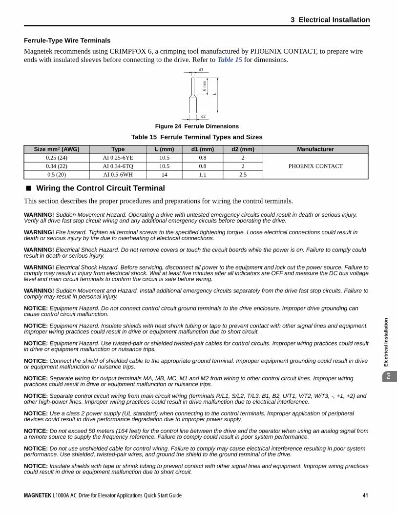
3 Electrical Installation
MAGNETEK L1000A AC Drive for Elevator Applications Quick Start Guide 41
Ele
ctri
cal I
nsta
llatio
n
3
Ferrule-Type Wire Terminals
Magnetek recommends using CRIMPFOX 6, a crimping tool manufactured by PHOENIX CONTACT, to prepare wire ends with insulated sleeves before connecting to the drive. Refer to Table 15 for dimensions.Figure 26
Figure 24 Ferrule Dimensions
Table 15 Ferrule Terminal Types and Sizes
■ Wiring the Control Circuit Terminal
This section describes the proper procedures and preparations for wiring the control terminals.
WARNING! Sudden Movement Hazard. Operating a drive with untested emergency circuits could result in death or serious injury. Verify all drive fast stop circuit wiring and any additional emergency circuits before operating the drive.
WARNING! Fire hazard. Tighten all terminal screws to the specified tightening torque. Loose electrical connections could result in death or serious injury by fire due to overheating of electrical connections.
WARNING! Electrical Shock Hazard. Do not remove covers or touch the circuit boards while the power is on. Failure to comply could result in death or serious injury.
WARNING! Electrical Shock Hazard. Before servicing, disconnect all power to the equipment and lock out the power source. Failure to comply may result in injury from electrical shock. Wait at least five minutes after all indicators are OFF and measure the DC bus voltage level and main circuit terminals to confirm the circuit is safe before wiring.
WARNING! Sudden Movement and Hazard. Install additional emergency circuits separately from the drive fast stop circuits. Failure to comply may result in personal injury.
NOTICE: Equipment Hazard. Do not connect control circuit ground terminals to the drive enclosure. Improper drive grounding can cause control circuit malfunction.
NOTICE: Equipment Hazard. Insulate shields with heat shrink tubing or tape to prevent contact with other signal lines and equipment. Improper wiring practices could result in drive or equipment malfunction due to short circuit.
NOTICE: Equipment Hazard. Use twisted-pair or shielded twisted-pair cables for control circuits. Improper wiring practices could result in drive or equipment malfunction or nuisance trips.
NOTICE: Connect the shield of shielded cable to the appropriate ground terminal. Improper equipment grounding could result in drive or equipment malfunction or nuisance trips.
NOTICE: Separate wiring for output terminals MA, MB, MC, M1 and M2 from wiring to other control circuit lines. Improper wiring practices could result in drive or equipment malfunction or nuisance trips.
NOTICE: Separate control circuit wiring from main circuit wiring (terminals R/L1, S/L2, T/L3, B1, B2, U/T1, V/T2, W/T3, -, +1, +2) and other high-power lines. Improper wiring practices could result in drive malfunction due to electrical interference.
NOTICE: Use a class 2 power supply (UL standard) when connecting to the control terminals. Improper application of peripheral devices could result in drive performance degradation due to improper power supply.
NOTICE: Do not exceed 50 meters (164 feet) for the control line between the drive and the operator when using an analog signal from a remote source to supply the frequency reference. Failure to comply could result in poor system performance.
NOTICE: Do not use unshielded cable for control wiring. Failure to comply may cause electrical interference resulting in poor system performance. Use shielded, twisted-pair wires, and ground the shield to the ground terminal of the drive.
NOTICE: Insulate shields with tape or shrink tubing to prevent contact with other signal lines and equipment. Improper wiring practices could result in drive or equipment malfunction due to short circuit.
Size mm2 (AWG) Type L (mm) d1 (mm) d2 (mm) Manufacturer0.25 (24) AI 0.25-6YE 10.5 0.8 2
PHOENIX CONTACT0.34 (22) AI 0.34-6TQ 10.5 0.8 20.5 (20) AI 0.5-6WH 14 1.1 2.5
d1
d2
6 m
m
L

3 Electrical Installation
42 MAGNETEK L1000A AC Drive for Elevator Applications Quick Start Guide
Wire the control circuit only after terminals have been properly grounded and main circuit wiring is complete. Refer to Figure 25 for details. Prepare the ends of the control circuit wiring as shown in Figure 26. Refer to Wire Size and Torque Specifications on page 40.
WARNING! Do not tighten screws beyond the specified tightening torque. Failure to comply may result in erroneous operation, damage the terminal block, or cause injury due to fire from overheating of loose electrical connections.
NOTICE: Use shielded twisted-pair cables as indicated to prevent operating faults. Improper wiring practices could result in drive or equipment malfunction due to electrical interference.
Connect control wires as shown in Figure 25:Figure 27
Figure 25 Terminal Board Wiring Guide
When connecting control wires to the terminals, use shielded twisted-pair wires (treating wire ends as shown in Figure 26 and connect the shield to the ground terminal (E [G]) of the drive.Figure 28
Figure 26 Preparing the Ends of Shielded Cables
NOTICE: Do not exceed 50 meters (164 ft.) for the control line between the drive and the operator when using an analog signal from a remote source to supply the frequency reference. Failure to comply could result in poor system performance.
A – Loosen screw to insert wire C – Avoid fraying wire strands when stripping insulation from wire. Strip length 5.5 mm.
B – Single wire or stranded wire D – Blade depth of 0.4 mm or less Blade width of 2.5 mm or less
A – Drive side D – Shield sheath (insulate with tape or heat-shrink tubing)B – Insulation E – ShieldC – Control device side
A
B
C
DPreparing wireterminal ends
AE B
C
D

3 Electrical Installation
MAGNETEK L1000A AC Drive for Elevator Applications Quick Start Guide 43
Ele
ctri
cal I
nsta
llatio
n
3
■ Switches and Jumpers on the Terminal Board
The terminal board is equipped with several switches used to adapt the drive I/Os to the external control signals. Figure 27 shows the location of these switches. Refer to Control I/O Configuration on page 44 for setting instructions.Figure 29
Figure 27 Locations of Jumpers and Switches on the Terminal Board
Off On
Jumper S3Terminal H1/H2 Sink/Source Sel.
DIP Switch S2RS-422/485 Termination
Resistor

3 Electrical Installation
44 MAGNETEK L1000A AC Drive for Elevator Applications Quick Start Guide
◆ Control I/O Configuration
■ Setting Sink/Source with Input Terminals SN and SP
Use the wire jumper between terminals SC and SP or SC and SN to select between Sink mode, Source mode or external power supply for the digital inputs S1 to S8 as shown in Table 16 (Default: Sink mode, internal power supply).
NOTICE: Damage to Equipment. Do not short terminals SP and SN. Failure to comply will damage the drive.
Table 16 Digital Input Sink / Source / External Power Supply Selection
Drive Internal Power Supply(Terminal SN and SP) External 24 Vdc Power Supply
Sinking Mode (NPN)
Sourcing Mode (PNP)
SC
S8
S7
24 VdcSP
SN
SC
S8
S7
24 VdcSP
SN
External 24 Vdc
SC
S8
S7
24 VdcSP
SN
SC
S8
S7
24 VdcSP
SN
External 24 Vdc

3 Electrical Installation
MAGNETEK L1000A AC Drive for Elevator Applications Quick Start Guide 45
Ele
ctri
cal I
nsta
llatio
n
3
■ Sinking/Sourcing Mode Selection for Safe Disable Inputs
Use jumper S3 on the terminal board to select between Sink mode, Source mode or external power supply for the Safe Disable inputs H1 and H2 as shown in Table 17 (Default: Sink mode, internal power supply.)
Table 17 Safe Disable Input Sink / Source / External Power Supply Selection
◆ Connect to a PC
This drive is equipped with a USB port (type-B).
The drive can connect to a USB port on a PC using a USB 2.0, AB-type cable (sold separately). After connecting the drive to a PC, Magnetek DriveWizard Plus software can be used to monitor drive performance and manage parameter settings. Contact Magnetek for more information on DriveWizard Plus.
Download and install the USB driver before connecting L1000A to a PC with the USB cable. To obtain the driver and software of USB Copy Unit, CopyUnitManager and DriveWizardPlus, visithttp://www.elevatordrives.comFigure 30
Figure 28 Connecting to a PC (USB)
Drive Internal Power Supply External 24 Vdc Power Supply
Sinking Mode
Sourcing Mode
24 Vdc
H1
H2
HC
Jumper S3
24 Vdc
H1
H2
HC
External24 Vdc
Jumper S3
24 Vdc
H1
H2
HC
Jumper S3
24 Vdc
H1
H2
HC
External24 Vdc
Jumper S3
PC
(Type-B) (Type-A)
USB Cable(Type-AB)

3 Electrical Installation
46 MAGNETEK L1000A AC Drive for Elevator Applications Quick Start Guide
◆ Wiring Checklist
No. Item Page
Drive, peripherals, option cards1 Check drive model number to ensure receipt of correct model. –
2 Make sure you have the correct braking resistors, DC link choke, noise filters, and other peripheral devices installed. –
3 Check the option card model number. –Installation area and physical setup
4 Ensure that the area surrounding the drive complies with specifications. 17Power supply voltage, output voltage
5 The voltage from the power supply should be within the input voltage specification range of the drive. –
6 The voltage rating for the motor should match the drive output specifications. 15177
7 Verify that the drive is properly sized to run the motor. 15177
Main circuit wiring8 Confirm proper branch circuit protection as specified by national and local codes. 21
9 Properly wire the power supply to drive terminals R/L1, S/L2, and T/L3. 24
10Properly wire the drive and motor together. The motor lines and drive output terminals R/T1, V/T2, and W/T3 should match in order to produce the desired phase order. If the phase order is incorrect, the drive will rotate in the opposite direction.
35
11 Use 600 Vac vinyl-sheathed wire for the power supply and motor lines. 30
12
Use the correct wire gauges for the main circuit. Refer to Wire Gauges and Tightening Torque on page 30. 30• Consider the amount of voltage drop when selecting wire gauges. Increase the wire gauge when the voltage
drop is greater than 2% of motor rated voltage. Ensure the wire gauge is suitable for the terminal block. Use the following formula to calculate the amount of voltage drop:Line drop voltage (V) = 3 × wire resistance (Ω/km) × wire length (m) × current (A) × 10-3
30
• If the cable between the drive and motor exceeds 50 m (164 feet), adjust the carrier frequency set to C6-02 accordingly.
36
13 Properly ground the drive. Review page 36. 36
14 Tightly fasten all terminal screws (control circuit terminals, grounding terminals).Refer to Wire Gauges and Tightening Torque on page 30. 30
15 Install a magnetic contactor when using a dynamic braking option. Properly install the resistor and ensure that overload protection shuts off the power supply using the magnetic contactor. –
16 Verify phase advancing capacitors, input noise filters, or ground fault circuit interrupters are NOT installed on the output side of the drive. –
Control circuit wiring17 Use twisted-pair line for all drive control circuit wiring. 37
18 Connect the shields of shielded wiring to the ground terminal (E [G] ). 41
19 Properly wire any option cards. 40
20 Check for any other wiring mistakes.Only use a multimeter to check wiring. –
21 Properly fasten the control circuit terminal screws in the drive.Refer to Wire Gauges and Tightening Torque on page 30. 30
22 Pick up all wire clippings. –
23 Ensure that no frayed wires on the terminal block are touching other terminals or connections. –
24 Properly separate control circuit wiring and main circuit wiring. –
25 Analog signal line wiring should not exceed 50 m (164 ft.). –
26 Safe Disable input wiring should not exceed 30 m (98 ft.). –

4 Start-Up Programming & Operation
MAGNETEK L1000A AC Drive for Elevator Applications Quick Start Guide 47
Sta
rt-U
p P
rogr
amm
ing
&O
ti4
4 Start-Up Programming & Operation
◆ Using the Digital Operator
Use the digital operator to enter Run and Stop commands, edit parameters, and display data including fault and alarm information.
■ Keys and DisplaysFigure 31
Figure 29 Keys and Displays on the Digital Operator
No. Display Name Function
1 Function Key(F1, F2)
The functions assigned to F1 and F2 vary depending on the currently displayed menu. The name of each function appears in the lower half of the display window.
2 ESC Key• Returns to the previous display.• Moves the cursor one space to the left.• Pressing and holding this button will return to the Speed Reference display.
3 RESET Key • Moves the cursor to the right.• Resets the drive to clear a fault situation.
4 RUN Key
Starts the drive in the LOCAL mode.The Run LED• is on, when the drive is operating the motor.• flashes during deceleration to stop or when the speed reference is 0.• flashes quickly, the drive is disabled by a DI, the drive was stopped using a fast stop
DI, or an Up/Down command was active during power up.
5 Up Arrow Key Scrolls up to display the next item, select parameter numbers, and increment setting values.
6 Down Arrow Key Scrolls down to display the previous item, select parameter numbers, and decrements setting values.
7 STOP Key <1> Stops drive operation.
8 ENTER Key • Enters parameter values and settings. • Selects a menu item to move between displays.
9 LO/RE Selection Key <2>
Switches drive control between the operator (LOCAL) and the control circuit terminals (REMOTE) for the Run command and speed reference. The LED is on when the drive is in the LOCAL mode (operation from keypad).
10 RUN Light Lit while the drive is operating the motor. Refer to page 50 for details.
11 LO/RE Light Lit while the operator is selected to run the drive (LOCAL mode). Refer to page 50 for details.
LORE
F2F1
ESC
RUN STOP
ENTERRESET
ALMDIGITAL OPERATOR JVOP-180 12
11
98
1
2
310
4 5 6 7
F1
F2
ESC
RESET
RUN
STOP
ENTER
LORE
RUN
LORE

4 Start-Up Programming & Operation
48 MAGNETEK L1000A AC Drive for Elevator Applications Quick Start Guide
■ LCD DisplayFigure 32
Figure 30 LCD Display
Table 18 Display and Contents
12 ALM LED Light Refer to ALARM (ALM) LED Displays on page 50.
<1> The STOP key has highest priority. Pressing the STOP key will always cause the drive to stop the motor, even if an Up/Down command is active at any external Up/Down command source. To disable the STOP key priority, set parameter o2-02 to 0.
<2> The LO/RE key can only switch between LOCAL and REMOTE when the drive is stopped. By default settings the LO/RE key function is disabled. To allow using the LO/RE key for switching between LOCAL and REMOTE, set parameter o2-01 to 1.
No. Name Display Content
1 Operation Mode Menus
MODE Displayed when in Mode Selection.MONITR Displayed when in Monitor Mode.VERIFY Indicates the Verify Menu.PRMSET Displayed when in Parameter Setting Mode.A.TUNE Displayed during Auto-Tuning.SETUP Displayed when in Setup Mode.
2 Mode Display AreaDRV Displayed when in Drive Mode.PRG Displayed when in Programming Mode.
3 Ready Rdy Indicates the drive is ready to run.4 Data Display – Displays specific data and operation data.
5 Speed Reference Source Assignment <1>
OPR Displayed when the speed reference source is assigned to the LCD Operator.
COM Displayed when the speed reference source is assigned to MEMOBUS/Modbus Communication.
OP Displayed when the speed reference is assigned to an option card.
6 LO/REDisplay <2>
RSEQ Displayed when the Up/Down command is supplied from a remote source.LSEQ Displayed when the Up/Down command is supplied from the operator keypad.RREF Displayed when the speed reference is supplied from a remote source.LREF Displayed when the speed reference is supplied from the operator keypad.
7 Function Key 1(F1)
HELP Pressing displays the Help menu.
← Pressing scrolls the cursor to the left.
HOME Pressing returns to the top menu (Speed Reference).
ESC Pressing returns to the previous display.
8 FWD/REVFWD During Up commandREV During Down command
No. Display Name Function
- MODE -
U1-01= 0.00%U1-02= 0.00%U1-03= 0.00A
DRVSpeed Ref (OPR)
Rdy
RSEQLREF
FWD
6
54
1 2 3
789
F1
F1
F1
F1

4 Start-Up Programming & Operation
MAGNETEK L1000A AC Drive for Elevator Applications Quick Start Guide 49
Sta
rt-U
p P
rogr
amm
ing
&O
ti4
■ Powering Up the Drive and Operation Status DisplayPowering Up the Drive
Perform the following power-off checks before applying main power to the drive.
WARNING! Electrical Shock Hazard. Do not contact live electrical parts. Failure to comply could result in death or serious injury. Never touch the output terminals directly with your hands or allow the output lines to come into contact with the drive case.
WARNING! Sudden Movement Hazard. Operating a drive with untested emergency circuits could result in death or serious injury. Always check the operation of drive fast stop circuits and any additional emergency circuits after they are wired. Fast stop circuits are required to provide safe and quick shutdown of the drive.
WARNING! Sudden Movement Hazard. Ensure start/stop and safety circuits are wired properly and in the correct state before energizing the drive. Failure to comply could result in death or serious injury from moving equipment.
Status Display
When the power supply to the drive is turned on, the digital operator lights will appear as follows:
9 Function Key 2(F2)
FWD/REV Pressing switches between Up and Down when the Up/Down command is set from the digital operator.
DATA Pressing scrolls to the next display.
→ Pressing scrolls the cursor to the right.
RESET Pressing resets the existing drive fault or error.
<1> Displayed when in Drive Mode.<2> Displayed when in Drive Mode and Monitor Mode.
Power-off Checks Description
Power supply voltage
Ensure the power supply voltage is correct on the supply side of the disconnect, before applying power to the drive. 200 V class: 3-phase 200 to 240 Vac 50/60 Hz 400 V class: 3-phase 380 to 480 Vac 50/60 HzProperly wire the power supply input terminals (R/L1, S/L2, T/L3). Check for correct wiring, terminals are tightened, and there are no loose wire strands.Check for proper grounding of drive and motor.
Drive output terminals and motor terminals
Properly wire drive output terminals U/T1, V/T2, and W/T3 with motor terminals U/T1, V/T2, and W/T3. Check for correct wiring, terminals are tightened, and there are no loose wire strands.
Control circuit terminals Check control circuit terminal connections. Check that control circuit terminals are correctly wired, terminals are tightened, and there are no loose wire strands.
Drive control terminal status Open all control circuits to the drive I/O terminal block.
No. Name Description
Normal Operation
The data display area in the upper half of the display, displays the speed reference. DRV is displayed.
Fault
External fault (example)
Data displayed varies by the type of fault. Refer to Fault Displays, Causes, and Possible Solutions on page 110 for more information and possible solutions. ALM LED is lit and DRV displayed.
No. Name Display Content
F1
F1
F1
F1
DIGITAL OPERATOR JVOP-180 ALM
- MODE -
U1-01= 0.00%U1-02= 0.00%U1-03= 0.00A
DRVSpeed Ref (OPR)
Rdy
FWD
RSEQLREF
DIGITAL OPERATOR JVOP-180 ALM
- MODE -
EF3Ext Fault S3
DRV
FWD RESET

4 Start-Up Programming & Operation
50 MAGNETEK L1000A AC Drive for Elevator Applications Quick Start Guide
■ ALARM (ALM) LED DisplaysTable 19 ALARM (ALM) LED Status and Contents
■ LO/RE LED and RUN LED IndicationsTable 20 LO/RE LED and RUN LED Indications
State Content Display
Illuminated When the drive detects an alarm or error.
Flashing• When an alarm occurs.• When oPE is detected.• When a fault or error occurs during Auto-Tuning.
Off Normal operation (no fault or alarm).
LED Lit Flashing Flashing Quickly OffWhen source of the Up/Down command is assigned to the digital operator (LOCAL).
– –Up/Down command to be given from a device other than the digital operator (REMOTE).
During run
• During deceleration to stop.• When an Up/Down command
is input and speed reference is 0%.
• While the drive is set for LOCAL, an Up/Down command was entered to the input terminals after which the drive was then switched to REMOTE.
• An Up/Down command was entered via the input terminals while not in the Drive Mode.
• During deceleration when a Fast Stop command was entered.
• The drive output is shut off by the Safe Disable function.
• While the drive was running in the REMOTE mode, the STOP key was pushed.
During stop
Examples
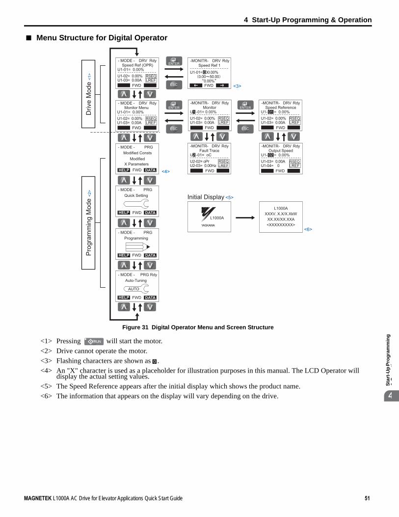
4 Start-Up Programming & Operation
MAGNETEK L1000A AC Drive for Elevator Applications Quick Start Guide 51
Sta
rt-U
p P
rogr
amm
ing
&O
ti4
■ Menu Structure for Digital OperatorFigure 33
Figure 31 Digital Operator Menu and Screen Structure
<1> Pressing will start the motor.<2> Drive cannot operate the motor.<3> Flashing characters are shown as .<4> An "X" character is used as a placeholder for illustration purposes in this manual. The LCD Operator will
display the actual setting values.<5> The Speed Reference appears after the initial display which shows the product name.<6> The information that appears on the display will vary depending on the drive.
- MODE -
U1-01= 0.00%U1-02= 0.00%U1-03= 0.00A
DRVSpeed Ref (OPR)
Rdy -MONITR-Speed Ref 1
U1-01= 000.00%
<3>
<4>
0.00 50.000.00%
DRV
← →FWD
Rdy
- MODE -
U1-01= 0.00%U1-02= 0.00%U1-03= 0.00A
DRVMonitor Menu
Rdy
- MODE - PRGModified Consts
HELP
HELP
DATA
- MODE - PRGQuick Setting
DATA
HELP
- MODE - PRG RdyAuto-Tuning
DATA
HELP
- MODE - PRG
DATA
Programming
AUTO
-MONITR-
U1 -01= 0.00%U1-02= 0.00%U1-03= 0.00A
DRVMonitor
FWD
Rdy -MONITR-
U1- 01 = 0.00%U1-02= 0.00%U1-03= 0.00A
DRVSpeed Reference
FWD
Rdy
-MONITR-
U1- 02 = 0.00%U1-03= 0.00AU1-04= 0
DRVOutput Speed
FWD
Rdy-MONITR-
U2 -01= oCU2-02= oPrU2-03= 0.00Hz
DRVFault Trace
FWD
Rdy
FWD
FWD
FWD
FWD
FWD
ModifiedX Parameters
RSEQLREF
RSEQLREF
RSEQLREF
RSEQLREF
RSEQLREF
RSEQLREF
YASKAWA
L1000A
L1000AXXXV X.X/X.XkW
XX.XX/XX.XXA<XXXXXXXXX>
Initial Display <5>
<6>
Pro
gram
min
g M
ode
<2>
Driv
e M
ode
<1>
FWD
RUN
0

4 Start-Up Programming & Operation
52 MAGNETEK L1000A AC Drive for Elevator Applications Quick Start Guide
◆ The Drive and Programming Modes
The drive has a Drive Mode to operate the motor and a Programming Mode to edit parameter settings.
Drive Mode: In Drive Mode the user can operate the motor and observe U Monitor parameters. Parameter settings cannot be edited or changed when in Drive Mode.
Programming Mode: In Programming Mode the user can edit and verify parameter settings and perform Auto-Tuning. The drive will not accept an Up/down command when the digital operator is in the Programming Mode unless parameter b1-08 is set to 1 to allow an Up/down command.
■ Changing Parameter Settings or Values
This example explains changing C1-02 (Deceleration Ramp 1) from 1.50 seconds (default) to 2.50 seconds.
Step Display/Result
1. Turn on the power to the drive. The initial display appears.
2. Press or until the Parameter Setting Mode screen appears.
3. Press to enter the parameter menu tree.
4. Press or to select the C parameter group.
5. Press two times.
6. Press or to select the parameter C1-02.
7. Press to view the current setting value (1.5 s). The left most digit flashes.
8. Press , or until the desired number is selected. “1” flashes.
9. Press and enter 0020.0.
- MODE -
U1-01= 0.00%U1-02= 0.00%U1-03= 0.00A
DRVSpeed Ref (OPR)
Rdy
RSEQLREF
FWD
HELP
- MODE - PRG
DATA
Programming
FWD
← →
-PRMSET-Initialization
Select Language
PRG
FWD
A1-00= 0
-PRMSET-Basic Setup
Accel Ramp 1
PRG
FWD
C1-01 = 1.50 sec
-PRMSET-Accel/Decel
Accel Ramp 1
PRG
FWD
C1-01= 1.50 sec
-PRMSET-
C1-01= 1.50 sec(0.0~600.00)
“1.50 sec”
PRGAccel Ramp 1
FWD
← →
-PRMSET-
C1-02= 1.50 sec(0.0~600.00)
“1.50 sec”
PRGDecel Ramp 1
FWD
-PRMSET-
C1-02= 001.50 sec(0.0~600.00)
“1.50 sec”
PRGDecel Ramp 1
FWD
F1
left
F2
right
-PRMSET-
C1-02=001.50 sec(0.0~600.00)
“1.50 sec”
PRGDecel Ramp 1
FWD
-PRMSET-
C1-02=002.50 sec(0.0~600.00)
“1.50 sec”
PRGDecel Ramp 1
FWD

4 Start-Up Programming & Operation
MAGNETEK L1000A AC Drive for Elevator Applications Quick Start Guide 53
Sta
rt-U
p P
rogr
amm
ing
&O
ti4
■ Simplified Setup Using the Setup Group
In the Setup Group, the drive lists the basic parameters needed to set up the drive for an elevator application. This group expedites the startup process for an elevator application by showing only the most important parameters for the application.
Using the Setup Group
Figure 32 illustrates how to enter and how to change parameters in the Setup Group.
The first display shown when entering the Setup Group is the Control Method menu. Skipping this display will keep the current Setup Group parameter selection. The default setting for the Setup Group is a group of parameters most commonly use in control methods.
In this example, the Setup Group is accessed to change b1-01 from 0 to 1. This changes the source of the speed reference from the digital operator to the control circuit terminals.
Figure 32 Setup Group Example
10. Press to confirm the change.
11. The display automatically returns to the screen shown in Step 4.
12. Press as many times as necessary to return to the initial display.
<1> Use the up and down arrow keys to scroll through the Setup Group. Press the ENTER key to view or change parameter settings.<2> To return to the previous menu without saving changes, press the ESC key.
Step Display/Result
Entry Accepted
-PRMSET-
C1-02= 2.50 sec(0.0~600.00)
“1.50 sec”
PRGDecel Ramp 1
FWD
- MODE -
U1-01= 0.00%U1-02= 0.00%U1-03= 0.00A
DRVSpeed Ref (OPR)
Rdy
RSEQLREF
FWD
← →
← →
- MODE -
U1-01= 0.00%U1-02= 0.00%U1-03= 0.00A
DRVSpeed Ref (OPR)
Rdy
RSEQLREF
Control CircuitTerminal
Operator
<1>
<2>
<2>
Speed referenceappears when powered up
HELP
- MODE - PRGQuick Setting
DATAFWD
Entry Accepted
- SETUP -
b1-01= 0 ∗0∗Operator
PRGSpeed Ref Sel
Rdy
Home FWD DATA
- SETUP -
A1-02= 2 ∗2∗Open Loop Vector
PRGControl Method
Rdy
Home FWD DATA
- SETUP -
b1-02= 1 ∗1∗Digital Inputs
PRGUp/Dn Command Sel
Rdy
Home FWD DATA
- SETUP -
L3-01= 1 ∗1∗General Purpose
PRGStallP Accel Sel
Rdy
Home FWD DATA
“1”
- SETUP -
b1-01= 0 ∗0∗Operator
PRGSpeed Ref Sel
Rdy
FWD
“1”
- SETUP -
b1-01= 0 ∗0∗Analog Input
PRGSpeed Ref Sel
Rdy
FWD
FWD

4 Start-Up Programming & Operation
54 MAGNETEK L1000A AC Drive for Elevator Applications Quick Start Guide
■ Switching Between LOCAL and REMOTE
LOCAL mode is when the drive is set to accept the Up/Down command from the digital operator keypad. REMOTE mode is when the drive is set to accept the Up/Down command from an external device (via the input terminals or serial communications, etc.).
Switch the operation between LOCAL and REMOTE using the LO/RE key on the digital operator or via a digital input. This key is disabled with default settings, but can be enabled by setting parameter o2-01 to 1.
Note: 1. After selecting LOCAL, the LO/RE light will remain lit.2. The drive will not allow the user to switch between LOCAL and REMOTE during run.
Using the LO/RE Key on the Digital Operator
◆ Start-Up Flowcharts
This section covers basic setup for the drive, including Auto-Tuning procedures and corresponding flowcharts. Follow the flowchart that matches the motor used in your application. Refer to Types of Auto-Tuning on page 61 for details on the types of Auto-Tuning.
Step Display/Result
1. Turn on the power to the drive. The initial display appears.
2.Press . The LO/RE light will light up. The drive is now in LOCAL.
To set the drive for REMOTE operation, press again.
Flowchart Purpose PageA Installation, wiring, and basic steps required to setup the motor and elevator for operation. 55B Auto-Tuning for induction motors. 58C Auto-Tuning for PM motors. 59D Encoder Offset Auto-Tuning 60
- MODE -
U1-01= 0.00%U1-02= 0.00%U1-03= 0.00A
DRVSpeed Ref(A1/A2)
Rdy
RSEQRREF
FWD
LORE
F2F1
ESC
RUN STOP
ENTERRESET
ALMDIGITAL OPERATOR JVOP-180
- MODE -
U1-01= 0.00%U1-02= 0.00%U1-03= 0.00A
DRVSpeed Ref (OPR)
Rdy
LSEQLREF
FWD
-

4 Start-Up Programming & Operation
MAGNETEK L1000A AC Drive for Elevator Applications Quick Start Guide 55
Sta
rt-U
p P
rogr
amm
ing
&O
ti4
■ Flowchart A: Installation, Wiring, Basic Setup for Motor and Elevator
The flowchart below covers the basic procedure required to install the drive, motor, and elevator. Figure 34
Figure 33 Installation, Wiring, Basic Setup for Motor and Elevator
Note: Set parameter H5-11 to 1 when setting parameters using MEMOBUS/Modbus communications.
For control modes below, refer to • V/f Control• Open Loop Vector Control• Closed Loop Vector ControlFor Closed Loop Vector for PM, refer to
START
Install the drive as explained in
Wire the drive as explained in
Check the PG encoder power supply selection.(Closed Loop Vector Control only -CLV)
Apply main power to the drive.Adhere to safety messages concerning application of power.
Perform Auto-Tuning for motor parameters and the PG encoder offset.
Determine the source of the speed
reference.
Analog Input
Digital operator (b1-01 = 0)(Speed selection by digital inputs)
Assign functions to the analog/digital I/O terminals using parameters H1-��, H2-��, H3-��, and H.4-��.
Set up:• Acceleration/deceleration ramp (C1-��)• Jerk settings (C2-��)
Perform a test run.
Fine-tuning• Adjust settings for the brake sequence (S1-��) .• Adjust speed control loop (C5-��) etc.
FINISH
Set up:• Preset speed references (d1-��)• Acceleration/deceleration ramp (C1-��)• Jerk settings (C2-��)
Assign functions to the digital I/O terminals using parameters H1-�� and H2-��.
Set the Speed Reference Selection modeparameter d1-18.
Set the Unit Length in parameter o1-12.Set up o1-20 to o1-22 and then select the display units for speed,
acceleration and deceleration ramp and jerk settings in o1-03.
Set up the Inspection Operation sequence.
Set up the PG encoder feedback in F1-�� parameters when using a Closed Loop Vector Control and check the PG encoder rotation direction.
Select the control mode in parameter A1-02.
Check the motor rotation direction.
Flowchart B: Auto-Tuning for Induction Motors on page 58.
Flowchart C: Auto-Tuning for PM Motors on page 59.
Mechanical Installation on page 17.
Main Circuit Wiring on page 29.

4 Start-Up Programming & Operation
56 MAGNETEK L1000A AC Drive for Elevator Applications Quick Start Guide
■ Power On
Take the following precautions before applying main power to the drive:
WARNING! Sudden Movement Hazard. Ensure start/stop, I/O and safety circuits are wired properly and in the correct state before energizing or running the drive. Failure to comply could result in death or serious injury from moving equipment.
WARNING! Fire Hazard. Do not use an improper voltage source. Failure to comply could result in death or serious injury by fire. Verify that the rated voltage of the drive matches the voltage of the incoming power supply before applying power.
WARNING! Fire Hazard. Loose electrical connections could result in death or serious injury by fire due to overheating of electrical connections. Tighten all terminal screws to the specified tightening torque.
WARNING! Fire Hazard. Do not connect the AC power line to the output motor terminals of the drive. Failure to comply could result in death or serious injury by fire as a result of drive damage from line voltage application to output terminals.
• Do not connect AC line power to output terminals U/T1, V/T2, and W/T3.• Make sure that the power supply lines are connected to main circuit input terminals R/L1, S/L2, and T/L3
(or R/L1 and S/L2 for single-phase power).
WARNING! Sudden Movement Hazard. Clear personnel, secure equipment and check sequence and safety circuitry before starting the drive. Failure to comply could result in death or serious injury from moving equipment.
• Clear all personnel from the drive, motor, and machine area.• Secure covers, couplings, shaft keys, and machine loads.• Ensure start/stop and safety circuits are wired properly and in the correct state.
WARNING! Sudden Movement Hazard. Operating a drive with untested emergency circuits could result in death or serious injury. Always check the operation of drive fast stop circuits and any additional emergency circuits after they are wired. Fast stop circuits are required to provide safe and quick shutdown of the drive.
NOTICE: Equipment Hazard. Comply with proper wiring practices. The motor may run in reverse if the phase order is backward. Connect motor input terminals U/T1, V/T2, and W/T3 to drive output terminals U/T1,V/T2, and W/T3. The phase order for the drive and motor should match.
NOTICE: Equipment Hazard. Check all the wiring including the PG encoder wiring and PG option jumper settings, to ensure that all connections are correct after installing the drive and connecting any other devices. Failure to comply could result in damage to the drive.
After applying the power, the drive mode display should appear and no fault or alarm should be displayed. In the event of a drive fault or error code, refer to Troubleshooting on page 110.
■ Control Mode Selection
Select one of the four motor control modes after applying power to the drive. Note that Closed Loop Vector modes require PG encoder feedback cards. The table below indicates possible control modes depending on the motor type and shows the required encoder feedback card.
Machine Type Control Mode A1-02 setting Encoder Option Card
Induction motor without encoderV/f Control 0 No card requiredOpen Loop Vector Control 2 No card required
Induction motor with incremental encoder Closed Loop Vector Control 3 PG-B3 / PG-X3Permanent magnet motor with EnDat 2.1/01, EnDat 2.2/01, or EnDat 2.2/22 encoder Closed Loop Vector Control for PM motors 7 PG-F3
Permanent magnet motor with ERN1387 or ERN487 encoder Closed Loop Vector Control for PM motors 7 PG-E3
Magnetek IPM motor with incremental encoder Closed Loop Vector Control for PM motors 7 PG-X3

4 Start-Up Programming & Operation
MAGNETEK L1000A AC Drive for Elevator Applications Quick Start Guide 57
Sta
rt-U
p P
rogr
amm
ing
&O
ti4
■ Motor Rotation Direction Setup
Check the direction of motor rotation to verify the Up command causes the elevator to move in the upward direction. Perform the following checks to confirm proper motor and load direction:
• The drive outputs motor voltage in U/T1-V/T2-W/T3 phase sequence when an Up command is issued. Check the motor rotation with this phase sequence (for most motors clockwise is seen from the shaft side).
• If the motor drives the elevator in up direction with a U/T1-V/T2-W/T3 sequence, make sure parameter b1-14 is set to 0.
• If the motor drives the elevator in down direction with a U/T1-V/T2-W/T3 sequence, make sure parameter b1-14 is set to 1. Motor direction may also be changed by reversing two motor leads connected to U/T1, V/T2, W/T3 on the drive terminal block.
DANGER! Electrical Shock Hazard. Do not connect or disconnect wiring while the power is on. Failure to comply will result in death or serious injury. Before servicing, disconnect all power to the equipment. The internal capacitor remains charged even after the power supply is turned off. The charge indicator LED will extinguish when the DC bus voltage is below 50 Vdc. To prevent electric shock, wait at least five minutes after all indicators are OFF and measure the DC bus voltage level to confirm safe level.
Note: Always perform motor rotation direction setup prior to setting the encoder rotation direction.
■ PG Encoder SetupPG Encoder Resolution Setup
Set the encoder resolution (incremental signal in the case of absolute encoders with Sin/Cos channels) in parameter F1-01.
PG Encoder Rotation Direction Setup
Perform the following steps to make sure the PG encoder rotation direction is set up correctly in the drive:
If information about the signal sequence of the PG encoder is available:
1. Check the sequence of PG encoder phases A and B when the motor drives the elevator in up direction.2. If the PG encoder A phase leads phase B, make sure F1-05 is set to 0.3. If the PG encoder B phase leads phase A, make sure F1-05 is set to 1.
If no information about the signal sequence of the PG encoder is available:
1. Turn the motor manually in elevator up direction while checking the value of monitor U1-05.2. If the value in U1-05 is positive, the set PG encoder direction is correct.3. If the value in U1-05 is negative, alter the setting of parameter F1-05.
Note: Always set the motor rotation direction prior to the encoder rotation direction. Refer to Motor Rotation Direction Setup on page 57.

4 Start-Up Programming & Operation
58 MAGNETEK L1000A AC Drive for Elevator Applications Quick Start Guide
■ Flowchart B: Auto-Tuning for Induction Motors
The flowchart below covers Auto-Tuning for induction motors operating with V/f Control, Open Loop Vector Control, or Closed Loop Vector Control.
Figure 34 Auto-Tuning for Induction Motors
<1> If an LED operator is used, the display shows “ ”.<2> If an LED operator is used, the display shows “ ”.
START
Set terminals H1 and H2 if the Safe Disable function is used.
Enter the data in to T1-�� parameters as indicated on the display.
Is the Control Mode V/f Control ?
Apply the brake if it was released during Auto-tuning.
FINISH
Can the motor rotate freely?
Select Stationary Auto-Tuning for Terminal Resistance only,
T1-01 = 2.
Select Stationary Auto-Tuning 1 or 2
T1-01 = 1 or 4.
NoA1-02=2 or 3
YesA1-02=0 No
Yes(Ropes removed)
Select Rotational Auto-TuningT1-01 = 0.
Press the Up key until “Tuning Ready” is displayed.
Enter the data in to T1-�� parameters as indicated on the display.
Press the Up key until “Tuning Ready” is displayed. <1>
Release the Brake.
Close the motor contactor(s).
Press the Run key on the digital operator and wait until Auto-Tuning is finished.
Set the Baseblock input (H1-��=8/9) if used.
Tuning Successful?
Refer to
Remove the source of Fault/Alarm and repeat Auto Tuning.
Open terminals H1-HC and H2-HC if used during the normal sequence.
Open the motor contactor(s).
Open the Baseblock input (H1-��=8/9) if used.
No(Alarm or Fault code
displayed Yes(“Entry Accepted”
displayed) <2>
<1>Auto-Tuning Fault Detection
on page 117.

4 Start-Up Programming & Operation
MAGNETEK L1000A AC Drive for Elevator Applications Quick Start Guide 59
Sta
rt-U
p P
rogr
amm
ing
&O
ti4
■ Flowchart C: Auto-Tuning for PM Motors
The flowchart below covers Auto-Tuning for permanent magnetic (PM) motors operating with Closed Loop Vector Control for PM motors.
Figure 35 Auto-Tuning for PM Motors
<1> If an LED operator is used, the display shows “ ”.<2> If an LED operator is used, the display shows “ ”.
Can the motor rotate freely?
START
Set terminals H1-HC and H2-HC if Safe Disable function is used.
Is the motor data sheet available?
FINISH
No
Yes
Select Stationary Auto-TuningT2-01 = 1.
Continue with encoder offset tuning.
Press the Run key on the digital operator and wait until Auto-Tuning is finished.
Set the Baseblock input (H1-��=8/9) if used.
Tuning Successful?
Refer to
Remove the Fault/Alarm source and repeat Auto Tuning.
Open terminals H1-HC and H2-HC if used during the normal sequence.
Open the motor contactor(s).
Open the Baseblock input (H1-��=8/9) if used.
No(Alarm or Fault code
displayed
Yes(“Entry Accepted” displayed <2>
Enter the data in to T2-�� parameters as indicated on the display.
Select Motor Data InputT2-01 = 0.
Enter the data in to T2-�� parameters as indicated on the display.
Press the Up key until “Tuning Ready” is displayed. <1>
Press the Up key until “Tuning Ready” is displayed. <1>
Close the motor contactor.
No(Alarm or Fault code
displayed
・ Select Rotational Back EMF Constant Auto-Tuning T2-01=11.・ Press the Up key.
Press the Run key on the digital operator and wait until Auto-Tuning is finished.
Yes (Ropes removed)
No
Refer to Flowchart D: PG Encoder Offset Auto-Tuning on page 60.
Auto-Tuning Fault Detection on page 117.

4 Start-Up Programming & Operation
60 MAGNETEK L1000A AC Drive for Elevator Applications Quick Start Guide
■ Flowchart D: PG Encoder Offset Auto-Tuning
The flowchart below covers Rotational and Stationary Auto-Tuning procedures used to automatically set up the PG encoder offset. PG encoder Offset Tuning should be performed when the PG encoder offset (T2-17) is unknown, when a PG encoder offset value has been set but problems with the speed feedback occur, or when the PG encoder is replaced.
Figure 36 PG Encoder Offset Auto-Tuning
<1> If an LED operator is used, the display shows “ ”.<2> If an LED operator is used, the display shows “ ”.
Press the Up key until “Tuning Ready” is displayed.
START
Has all motor and PG encoder data been
set correctly?
FINISH
No
Yes
Tuning Successful?
No
Set the motor and PG encoder data manually or perform motor data Auto-tuning.
Yes(Stationary PG Encoder Offset
Auto-Tuning possible)
Select Stationary Encoder Offset Auto-TuningT2-01 = 4.
Press the Run key on the digital operator and wait until Auto-Tuning is finished.
Press the Up key until “Tuning Ready” is displayed.
Select Rotational PG Encoder Offset Auto-Tuning T2-01 = 10.
Press the Run key on the digital operator and wait until Auto-Tuning is finished.
Uncouple motor and the mechanical system of the elevator (remove ropes).
Tuning Successful?
Yes
No - “Er-22” Rotational PG Encoder Offset Auto-Tuning necessary
Apply the brake.
Release the brake.
Refer to
Remove the Fault/Alarm source and repeat Auto Tuning.
Tuning Successful?
Refer to
Remove the Fault/Alarm source and repeat Auto Tuning.
No
Yes
Absolute PG encoder used?
Absolute PG encoder necessary for driving the motor.
Change the PG option card and use an absolute PG Encoder
(EnDat, ...).
No
(PG-X3, Incremental PG encoder used)Yes
(EnDat, ...)
<1>
<2>
<1>
Set terminals H1-HC and H2-HC if Safe Disable function is used.Set the Baseblock input (H1-��=8/9) if used.
Close the motor contactor(s).
Select Initial Magnet Pole Search Parameter Auto-Tuning T2-01 = 3.Press the Up key until “Tuning Ready” is displayed.
Press the Run key on the digital operator and wait until Auto-Tuning is finished.
<1>
Open the motor contactor(s).Open the Baseblock input (H1-��=8/9) if used.
Open terminals H1-HC and H2-HC if used during the normal sequence.Recouple the motor (ropes) to the load if decoupled for tuning.
Auto-Tuning Fault Detection on page 117.
Auto-Tuning Fault Detection on page 117.

4 Start-Up Programming & Operation
MAGNETEK L1000A AC Drive for Elevator Applications Quick Start Guide 61
Sta
rt-U
p P
rogr
amm
ing
&O
ti4
■ Types of Auto-Tuning
The drive offers different types of Auto-Tuning for induction motors and permanent magnet motors. The type of Auto-Tuning used differs further based on the control mode and other operating conditions. Refer to the tables below to select the type of Auto-Tuning that bests suits the application. Directions for performing Auto-Tuning are listed in Start-Up Flowcharts on page 54.
Note: The drive will only show Auto-Tuning parameters that are valid for the control mode that has been set in A1-02. If the control mode is for an induction motor, the Auto-Tuning parameters for PM motors will not be available. If the control mode is for a PM motor, the Auto-Tuning parameters for induction motors will not be available. Inertia Tuning and ASR Gain Tuning parameters and setting options will be visible only when the drive is set for operation with CLV or CLV/PM.
Auto-Tuning for Induction MotorsTable 21 Types of Auto-Tuning for Induction Motors
Auto-Tuning for Permanent Magnet Motors
Automatically sets the V/f pattern and motor parameters E1- , E5- , and some F1- parameters for speed feedback detection.
Table 22 Types of Auto-Tuning for Permanent Magnet Motors
Type Setting Requirements and BenefitsControl Mode (A1-02)V/f (0) OLV (2) CLV (3)
Rotational Auto-Tuning
T1-01 = 0• Rotational Auto-Tuning gives the most accurate results, and is recommended if
possible.• Motor must run freely or with light load (<30%), i.e. ropes have to be removed.
No Yes Yes
Stationary Auto-Tuning 1
T1-01 = 1
• A motor test report listing motor data is not available.• Automatically calculates motor parameters needed for vector control.• Use if ropes can not be removed. Note that the accuracy is less then with
Rotational Auto-Tuning.
No Yes Yes
Stationary Auto-Tuning for Line-to-Line Resistance
T1-01 = 2
• Used for V/f Control or in vector control modes when the drive was previously set up properly and now the motor cable has changed.
• Used in V/f control if drive and motor capacities differ.• Should not be used for any vector control modes unless the motor cable has
changed.
Yes Yes Yes
Stationary Auto-Tuning 2
T1-01 = 4
• A motor test report is available. Once the no-load current and the rated slip have been entered, the drive calculates and sets all other motor-related parameters.
• Use if ropes can not be removed and if slip and no-load current data are available.
No Yes Yes
Type Setting Requirements and Benefits
Motor Data Input T2-01 = 0
• Use if a motor test report is available• Input motor data from the motor test report. Convert data into the correct unit before inputting data if
necessary.• Motor does not rotate during Auto-Tuning
Stationary Auto-Tuning T2-01 = 1• Use if a motor test report is not available• Input motor data from the motor name plate. Make sure to convert data into the correct units. The
drive automatically calculates the motor data.Stationary Stator Resistance Auto-Tuning T2-01 = 2 • Tunes stator resistance only.
• Should be performed if the motor cabling has changed.
Rotational Back EMF Constant Auto-Tuning T2-01 = 11
• Use if a motor test is not available• Tunes the Motor Induction Voltage only• Should be performed after Motor data are set and the encoder offset is adjusted.• The motor must be uncoupled from the mechanical system (remove ropes).

4 Start-Up Programming & Operation
62 MAGNETEK L1000A AC Drive for Elevator Applications Quick Start Guide
Table 23 Auto-Tuning Input Data
Properly set the motor and PG encoder data before performing PG Encoder Offset Tuning.
Table 24 Types of Auto-Tuning for PG Encoder Offset
Input Value
<1> Depends on T2-13 setting.
InputParameter Unit
Tuning Type (T2-01)
0Motor
Parameter Settings
1Stationary
2Stationary
StatorResistance
3Initial
Magnet Pole Search Parameters
Auto-Tuning
4Encoder Offset
Stationary Auto-
Tuning
10Encoder Offset
Rotational Auto-
Tuning
11Back EMFConstant
Control Mode A1-02 – 7 7 7 7 7 7 7Motor Rated Power T2-04 kW Yes Yes N/A N/A N/A N/A N/AMotor Rated Voltage T2-05 V Yes Yes N/A N/A N/A N/A N/AMotor Rated Current T2-06 A Yes Yes Yes N/A N/A N/A N/ANumber of Motor Poles T2-08 N/A Yes Yes N/A N/A N/A N/A N/AMotor Rated Speed T2-09 min-1 Yes Yes N/A N/A N/A N/A N/AStator 1 Phase Resistance T2-10 Ω Yes N/A N/A N/A N/A N/A N/Ad-Axis Inductance T2-11 mH Yes N/A N/A N/A N/A N/A N/Aq-Axis Inductance T2-12 mH Yes N/A N/A N/A N/A N/A N/AInduced Voltage Constant Unit Selection T2-13 N/A Yes N/A N/A N/A N/A N/A N/A
Voltage Constant T2-14 <1> Yes N/A N/A N/A N/A N/A N/APG Number of Pulses per Revolution T2-16 N/A Yes Yes N/A N/A N/A N/A N/A
Z Pulse Offset T2-17 deg (mech.) Yes N/A N/A N/A N/A N/A N/A
Type Setting Requirements and Benefits
Initial Magnet Pole Search Parameters Auto-Tuning T2-01 = 3
• Should be performed after motor Auto-Tuning in order to determine the PG encoder tuning method.• Attempts to detect the motor rotor position, determines whether PG encoder offset can be tuned using
Stationary Encoder Offset Tuning and sets parameters needed for Initial Magnet Pole Search (n8-36, n8-37).
• When using the Rescue Operation mode, perform this tuning to let the drive automatically set the parameters needed for Initial Magnet Pole Search with power supply from a battery or UPS (n8-81, n8-82).
• Must be performed when using an incremental PG encoder.Important: If this tuning fails when using a PG-X3 card with an incremental PG encoder the motor cannot be driven using an incremental PG encoder. Change the PG encoder to an absolute PG encoder.
Stationary PG Encoder Offset Auto-Tuning T2-01 = 4
• Tunes the PG encoder offset without rotating the motor.• If the PG encoder offset cannot be tuned properly by this method, try Rotating PG Encoder Offset
Tuning.Rotational PG Encoder
Offset Auto-Tuning T2-01 = 10 • Tunes the PG encoder offset while rotating the motor.• Motor and mechanical system must be uncoupled (ropes must be removed from traction sheave).

4 Start-Up Programming & Operation
MAGNETEK L1000A AC Drive for Elevator Applications Quick Start Guide 63
Sta
rt-U
p P
rogr
amm
ing
&O
ti4
■ Auto-Tuning Interruption and Fault Codes
If tuning results are abnormal or the STOP key is pressed before completion, Auto-Tuning will be interrupted and a fault code will appear on the digital operator.Figure 35
Figure 37 Auto-Tuning Aborted Display
■ Auto-Tuning Operation ExampleThe following example demonstrates Rotational Auto-Tuning when using OLV (A1-02 = 2).Selecting the Type of Auto-Tuning
Enter Data from the Motor NameplateAfter selecting the type of Auto-Tuning, enter the data required from the motor nameplate.
Note: These instructions continue from Step 6 in “Selecting the Type of Auto-Tuning”.
Step Display/Result
1. Turn on the power to the drive. The initial display appears.
2. Press or until the Auto-Tuning display appears.
3. Press to begin setting parameters.
4. Press to select the value for T1-01.
5. Save the setting by pressing .
6. The display automatically returns to the display shown in Step 3.
Step Display/Result
1. Press to access the motor output power parameter T1-02.
DIGITAL OPERATOR JVOP-180DIGITAL OPERATOR JVOP-180
REV DRV FOUTDRV
ALM ALM
Auto-Tuning AbortedDuring Auto-Tuning
- A.TUNE -
X.XX Hz/ X.XXA
DRVTune Proceeding
Rdy
FWD
- MODE -
Er-03STOP key
DRV
FWD RESET
- MODE -
U1-01= 0.00%U1-02= 0.00%U1-03= 0.00A
DRVSpeed Ref (OPR)
Rdy
FWD
RSEQLREF
HELP
- MODE - PRGAuto-Tuning
DATA
AUTO
FWD
- A.TUNE -
T1-01= 0 ∗0∗Standard Tuning
PRGTuning Mode
ESC FWD DATA
- A.TUNE -
T1-01= 0 ∗0∗Standard Tuning
PRGTuning Mode
FWD“0”
Entry Accepted
- A.TUNE -
T1-01= 0 ∗0∗Standard Tuning
PRGTuning Mode
ESC FWD DATA
- A.TUNE -
T1-02= 3.70kW(0.00 ~ 650.00)
PRGMtr Rated Power
ESC FWD DATA“3.70kW”

4 Start-Up Programming & Operation
64 MAGNETEK L1000A AC Drive for Elevator Applications Quick Start Guide
Starting Auto-TuningWARNING! Sudden Movement Hazard. The drive and motor may start unexpectedly during Auto-Tuning, which could result in death or serious injury. Ensure the areas surrounding the drive, motor and load are clear before proceeding with Auto-Tuning.
WARNING! Electrical Shock Hazard. High voltage will be supplied to the motor when Stationary Auto-Tuning is performed even with the motor stopped, which could result in death or serious injury. Do not touch the motor until Auto-Tuning has been completed.
WARNING! When performing Rotational Auto-Tuning for motor data or PG encoder offset, always uncouple the motor from the mechanical system (remove ropes from traction sheave). Performing Rotational Auto-Tuning with the mechanical system connected to the motor can cause hazardous situations, injury to personnel and damage to the equipment.
NOTICE: Rotational Auto-Tuning will not function properly if a holding brake is applied on the load. Ensure the motor can freely spin before beginning Auto-Tuning. Failure to comply could result in improper operation of the drive.
Enter the required information from the motor nameplate. Press to proceed to the Auto-Tuning start display.Note: These instructions continue from Step 6 in “Enter Data from the Motor Nameplate”.
2. Press to view the default setting.
3.Press , , , and to enter the motor power nameplate
data in kW.
4. Press to save the setting.
5. The display automatically returns to the display in Step 1.
6.
Repeat Steps 1 through 5 to set the following parameters:• T1-03, Motor Rated Voltage• T1-04, Motor Rated Current• T1-05, Motor Base Frequency• T1-06, Number of Motor Poles• T1-07, Motor Base Speed
Step Display/Result
1. After entering the data listed on the motor nameplate, press to confirm.
2.
Press to activate Auto-Tuning. The drive begins by injecting current into the motor for about 1 min, and then starts to rotate the motor.Note: The first digit on the display indicates which motor is undergoing Auto-Tuning (motor 1 or motor 2). The second digit indicates the type of Auto-Tuning being performed.
3. Auto-Tuning finishes in approximately one to two minutes.
Step Display/Result
- A.TUNE -
T1-02= 003.70kW(0.00 ~ 650.00)
PRGMtr Rated Power
FWD“3.70kW”
F1
left
F2
right
- A.TUNE -
T1-02= 004.00kW(0.00 ~ 650.00)
PRGMtr Rated Power
FWD“3.70kW”
Entry Accepted
- A.TUNE -
T1-02= 4.00kW(0.00 ~ 650.00)
PRGMtr Rated Power
ESC FWD DATA“3.70kW”
- A.TUNE -
T1-02= 4.00kW(0.00 ~ 650.00)
PRGMtr Rated Power
ESC FWD DATA“3.70kW”
- A.TUNE -
T1-07= 1450RPM(0 ~ 24000)
PRGRated Speed
ESC FWD DATA“1450RPM”
- A.TUNE -
0.00 Hz/ 0.00ATuning Ready ?
DRVAuto-Tuning
ESC FWDPress RUN key
- A.TUNE -
X.XX Hz/ X.XXA
DRVTune Proceeding
Rdy
FWD
- MODE -
EndTune Successful
DRV
FWD RESET

4 Start-Up Programming & Operation
MAGNETEK L1000A AC Drive for Elevator Applications Quick Start Guide 65
Sta
rt-U
p P
rogr
amm
ing
&O
ti4
■ Parameter Settings during Induction Motor Auto-Tuning: T1
The T1- parameters are used to set the Auto-Tuning input data for induction motor tuning.Note: For motors operating in the field weakening range, first perform the Auto-Tuning with the base data. After Auto-Tuning is
complete, change E1-04, Maximum Output Frequency, to the desired value.T1-01: Auto-Tuning Mode Selection
Sets the type of Auto-Tuning to be used. Refer to Auto-Tuning for Induction Motors on page 61 for details on the different types of Auto-Tuning.
Setting 0: Rotational Auto-TuningSetting 1: Stationary Auto-Tuning 1Setting 2: Stationary Auto-Tuning for Line-to-Line ResistanceSetting 4: Stationary Auto-Tuning 2T1-02: Motor Rated Power
Sets the motor rated power according to the motor nameplate value.
T1-03: Motor Rated Voltage
Sets the motor rated voltage according to the motor nameplate value. Enter the motor voltage at base speed here if the motor is operating above base speed.
Enter the voltage needed to operate the motor under no-load conditions at rated speed to T1-03 for better control precision around rated speed when using a vector control mode. The no-load voltage can usually be found in the motor test report available from the manufacturer. If the motor test report is not available, enter approximately 90% of the rated voltage printed on the motor nameplate. This may increase the output current and reduce the overload margin.
T1-04: Motor Rated Current
Sets the motor rated current according to the motor nameplate value. Set the motor rated current between 50% and 100% of the drive rated current for optimal performance in OLV or CLV. Enter the current at the motor base speed.
T1-05: Motor Base Frequency
Sets the motor rated frequency according to the motor nameplate value. If a motor with an extended speed range is used or if the motor is used in the field weakening area, enter the maximum frequency to E1-04 (E3-04 for motor 2) after Auto-Tuning is complete.
No. Name Setting Range Default
T1-01 Auto-Tuning Mode Selection 2 (V/f)0 to 2, 4 (OLV, CLV)
2 (V/f)1 (OLV, CLV)
No. Name Setting Range DefaultT1-02 Motor Rated Power 0.00 to 650.00 kW Determined by o2-04
No.
<1> Values shown are specific to 200 V class drives. Double value for 400 V class drives.
Name Setting Range DefaultT1-03 Motor Rated Voltage 0.0 to 255.5 V <1> 200.0 V <1>
No. Name Setting Range Default
T1-04 Motor Rated Current 10 to 200% of drive rated current Depending on o2-04
No. Name Setting Range DefaultT1-05 Motor Base Frequency 0.0 to 120.0 Hz 60.0 Hz

4 Start-Up Programming & Operation
66 MAGNETEK L1000A AC Drive for Elevator Applications Quick Start Guide
T1-06: Number of Motor Poles
Sets the number of motor poles according to the motor nameplate value.
T1-07: Motor Base Speed
Sets the motor rated speed according to the motor nameplate value. If a motor with an extended speed range is used or if the motor is used in the field weakening area, enter the speed at base frequency to T1-07.
T1-08: PG Number of Pulses Per Revolution
Sets the number of pulses from the PG encoder. Set the actual number of pulses for one full motor rotation.
Note: T1-08 will only be displayed in CLV.T1-09: Motor No-Load Current
Sets the no-load current for the motor. The default setting displayed is no-load current automatically calculated from the output power set in T1-02 and the motor rated current set to T1-04. Enter the data listed on the motor test report. Leave this data at the default setting if the motor test report is not available.
T1-10: Motor Rated Slip
Sets the rated slip for the motor.
The default setting displayed is the motor rated slip for a Magnetek motor calculated from the output power set in T1-02. Enter the data listed on the motor test report.
No. Name Setting Range DefaultT1-06 Number of Motor Poles 2 to 48 4
No. Name Setting Range DefaultT1-07 Motor Base Speed 0 to 24000 r/min 1750 r/min
No. Name Setting Range DefaultT1-08 PG Number of Pulses Per Revolution 0 to 60000 ppr 1024 ppr
No.
<1> The value will have two decimal places (0.01 A) in the drive models 2A0008 to 0033 and 4A0005 to 0018 (refer to Table 50 and Table 51), and one decimal place (0.1 A) in the drive models 2A0047 to 0415 and 4A0024 to 0260
Name Setting Range Default
T1-09 <1> Motor No-Load Current 0 to [T1-04] A(Max: 0 to 2999.9) –
No. Name Setting Range DefaultT1-10 Motor Rated Slip 0.00 to 20.00 Hz –

4 Start-Up Programming & Operation
MAGNETEK L1000A AC Drive for Elevator Applications Quick Start Guide 67
Sta
rt-U
p P
rogr
amm
ing
&O
ti4
■ Parameter Settings during PM Motor Auto-Tuning: T2
The T2- parameters are used to set the Auto-Tuning input data for PM motor tuning.
T2-01: PM Auto-Tuning Mode Selection
Selects the type of Auto-Tuning to be performed. Refer to Auto-Tuning for Permanent Magnet Motors on page 61 for details on different types of Auto-Tuning.
0: Motor Data Input1: PM Stationary Auto-Tuning2: PM Stationary Stator Resistance Auto-Tuning3: Initial Magnet Pole Search Parameters Auto-Tuning4: Stationary PG Encoder Offset Auto-Tuning10: Rotational PG Encoder Offset Auto-Tuning11: Rotational Back EMF Constant Auto-TuningT2-04: PM Motor Rated Power
Specifies the PM motor rated power in kilowatts.
T2-05: PM Motor Rated Voltage
Sets the PM motor rated voltage.
T2-06: PM Motor Rated Current
Enter the PM motor rated current in amps.
T2-08: Number of PM Motor Poles
Enter the number of motor poles.
T2-09: PM Motor Base Speed
Enter the motor rated speed in r/min.Note: T2-09 will be displayed when in CLV/PM.
No. Name Setting Range DefaultT2-01 PM Auto-Tuning Mode Selection 0 to 4, 10, 11 0
No. Name Setting Range DefaultT2-04 PM Motor Rated Power 0.00 to 650.00 kW Depending on o2-04
No. Name Setting Range Default
<1> Values shown are specific to 200 V class drives. Double value for 400 V class drives.T2-05 PM Motor Rated Voltage 0.0 to 255.0 V <1> 200.0 V <1>
No. Name Setting Range Default
T2-06 PM Motor Rated Current 10% to 200% of the drive rated current. Depending on o2-04
No. Name Setting Range DefaultT2-08 Number of PM Motor Poles 2 to 48 6
No. Name Setting Range DefaultT2-09 PM Motor Base Speed 0 to 24000 r/min 150 r/min

4 Start-Up Programming & Operation
68 MAGNETEK L1000A AC Drive for Elevator Applications Quick Start Guide
T2-10: PM Motor Stator Resistance
Enter the motor stator resistance per motor phase.
T2-11: PM Motor d-Axis Inductance
Enter the d axis inductance per motor phase.
T2-12: PM Motor q-Axis Inductance
Enter the q axis inductance per motor phase.
T2-13: Induced Voltage Constant Unit Selection
Selects the units used for setting the induced voltage coefficient.
0: mV (r/min)1: mV (rad/sec)
Note: If T2-13 is set to 0, then the drive will use E5-24 (Motor Induction Voltage Constant 2), and will automatically set E5-09 (Motor Induction Voltage Constant 1) to 0.0. If T2-13 is set to 1, then the drive will use E5-09 and will automatically set E5-24 to 0.0.
T2-14: PM Motor Induced Voltage Constant
Enter the motor induced voltage constant.
T2-16: PG Number of Pulses Per Revolution for PM Motor Tuning
Enter the number of pulses from the PG encoder per motor rotation.
T2-17: PG Encoder Z-pulse Offset
Sets the offset between the rotor magnet axis and the PG encoder zero position. If the PG encoder offset value is unknown or if the PG encoder is replaced, perform PG Encoder Offset Auto-Tuning.
No. Name Setting Range DefaultT2-10 PM Motor Stator Resistance 0.000 to 65.000 Ω –
No. Name Setting Range DefaultT2-11 PM Motor d-Axis Inductance 0.00 to 600.00 mH –
No. Name Setting Range DefaultT2-12 PM Motor q-Axis Inductance 0.00 to 600.00 mH –
No. Name Setting Range DefaultT2-13 Induced Voltage Constant Unit Selection 0, 1 1
No. Name Setting Range DefaultT2-14 PM Motor Induced Voltage Constant 0.0 to 2000.0 Depending on T2-02
No. Name Setting Range DefaultT2-16 Encoder Resolution (Pulses Per Revolution) 1 to 15000 ppr 1024 ppr
No. Name Setting Range DefaultT2-17 PG Encoder Z-pulse Offset -180.0 to 180.0 deg 0.0 deg

4 Start-Up Programming & Operation
MAGNETEK L1000A AC Drive for Elevator Applications Quick Start Guide 69
Sta
rt-U
p P
rogr
amm
ing
&O
ti4
◆ Setup Procedure for Elevator Applications
■ Up and Down Commands and Speed Reference Selection
WARNING! Sudden Movement Hazard. Remove the Up/Down Command before resetting alarms and faults. Failure to comply can result in death or serious injury.
WARNING! Sudden Movement Hazard. Verify drive parameter b1-03 Stopping Method is set to 0:Ramp to Stop before starting the drive. Failure to comply may cause the elevator to free-fall when the Up/Down command is removed.
WARNING! Sudden Movement Hazard. The drive is capable of running the motor at high speed. Verify the maximum drive output frequency before starting the drive. Failure to comply may cause injury or death due to inadvertent high speed operation.
WARNING! Sudden Movement Hazard. Use the Initial Pole Search Status Signal (H2- = 61) to interlock the brake to ensure the brake is not released before the Initial Magnetic Pole Search is completed. Failure to comply may cause inadvertent elevator movement resulting in serious injury.
NOTICE: Always turn off the RUN command before changing the setting of parameters d1-18 (Speed Reference Selection Mode), b1-01 (Speed Reference Selection), or H1- (Multi-Function Digital Inputs). If the RUN command is on when changing any of these settings, the motor may unexpectedly start running, and could result in injury.
Speed Reference Selection
Parameter b1-01 determines the source of the speed reference.
Up/Down Command Source Selection
The input source for the Up and Down command can be selected using parameter b1-02.
Travel Start and StopTravel Start
To start the elevator in up or down direction, the following conditions must be fulfilled:
• A speed reference greater than zero must be provided.• The Safe Disable signals at terminals H1 and H2 must both be closed (drive output enabled).• If a multi-function digital input is programmed for Baseblock (H1- =8 or 9), this input must be set so the drive is not
in a baseblock condition.• An Up or Down Signal must be set at the source specified in b1-02.• If a multifunction input is programmed for output contactor feedback (H1- =56), then the output contactor must be
closed.
b1-01 Reference source Speed reference input
0 (default)
<1> If source of the speed reference is assigned to the control terminals (b1-01 = 1), then d1-18 will automatically be set to 0 (so that the drive uses multi-speed references d1-01 to d1-08).
<2> If the speed reference selection in d1-18 is set so that either the high speed reference has priority (d1-18 = 1), or so that the leveling speed has priority (d1-18 = 2), then the drive will look to the multi-function input terminals for the speed reference.
Digital operator keypad Set the speed references in the d1- parameters and use digital inputs to switch between different reference values.
1 Analog input <1> Apply the speed reference signal to terminal A1 or A2.2 Serial Communication <2> Serial Communications using the RS422/485 port3 Option Board <2> Communications option card
b1-02 Up/Down source Up/Down command input0 Operator keypad RUN and STOP keys on the operator
1 (default) Digital inputs Terminal S1: Run in Up directionTerminal S2: Run in Down direction
2 Serial Communication Serial Communications using the RS422/485 port3 Option Board Communications option card

4 Start-Up Programming & Operation
70 MAGNETEK L1000A AC Drive for Elevator Applications Quick Start Guide
Travel Stop
The drive stops under the following conditions:
• The Up or Down command is removed.• d1-18 is set to 1 or 2 and the Up/Down or Leveling Speed signal (H1- = 53) is removed.• d1-18 is set to 3 and all speed inputs are removed.• A fault occurs. The stopping method depends on the specific fault that occurred, in combination with certain parameter
settings.• The Safe Disable inputs are opened or a Base Block signal is input. In this case, the brake is applied immediately and
the drive output shuts off.
■ Speed Selection Using Digital Inputs (b1-01 = 0)
Set parameter b1-01 = 0 to enable the speed selection using the drive digital inputs. Use parameter d1-18 to determine different travel speeds selected by the digital inputs.
NOTICE: Always turn off the RUN command before changing the setting of parameters d1-18 (Speed Reference Selection Mode), b1-01 (Speed Reference Selection), or H1- (Multi-Function Digital Inputs). If the RUN command is on when changing any of these settings, the motor may unexpectedly start running, and could result in injury.
Multi-Speed Inputs 1, 2 (d1-18 = 0 or 3) Speed Selection
When d1-18 = 0 or 3, multi-function digital inputs are preset as shown below.
Different speed reference settings can be selected by combining the three digital inputs as shown in the table below.Note: Parameters d1-19 through d1-26 are displayed only if d1-18 is set to 1 or 2.
d1-18 Speed Selection0 (default) Multi-speed inputs 1, Speed references are set in d1-01 to d1-08
1 Separate speed inputs, Speed references are set in d1-19 to d1-24 and d1-26, Higher speed has priority2 Separate speed inputs, Speed references are set in d1-19 to d1-24 and d1-26, Leveling speed has priority3 Multi speed inputs 2, Speed references are set in d1-02 to d1-08, Stop if no speed selection input is enabled
Terminal Parameter Number Set Value DetailsS5 H1-05 3 Multi-Speed Reference 1S6 H1-06 4 Multi-Speed Reference 2S7 H1-07 5 Multi-Speed Reference 3
Digital Inputs
0 = Off, 1 = On
Selected SpeedMulti-Speed Reference 1
Multi-Speed Reference 2
Multi-Speed Reference 3 d1-18 = 0 d1-18 = 3
0 0 0 Speed reference 1 (d1-01) Stop1 0 0 Speed reference 2 (d1-02 or terminal A1, A2 input value if H3-02 or H3-10 is set to 2)0 1 0 Speed reference 3 (d1-03 or terminal A1, A2 input value if H3-02 or H3-10 is set to 3)1 1 0 Speed reference 4 (d1-04)0 0 1 Speed reference 5 (d1-05)1 0 1 Speed reference 6 (d1-06)0 1 1 Speed reference 7 (d1-07)1 1 1 Speed reference 8 (d1-08)

4 Start-Up Programming & Operation
MAGNETEK L1000A AC Drive for Elevator Applications Quick Start Guide 71
Sta
rt-U
p P
rogr
amm
ing
&O
ti4
Setting d1-18 = 0
Up to eight speed references can be set using parameters d1-01 to d1-08. The drive starts with an Up or Down command, and stops when the Up or Down command is removed. When d1-18 = 0, parameters d1-19 through d1-23 will not be displayed.
Setting d1-18 = 3
Allows seven speed references to be set using parameters d1-02 to d1-08. The drive starts with an Up or Down command, and stops either when all three input terminals that set the speed reference are released, or when the Up/Down command is released. When d1-18 = 0, parameters d1-19 through d1-23 will not be displayed.
Separate Speed Inputs (d1-18 = 1 or 2)
Six different speed settings (defined in the parameters d1-19 to d1-24 and d1-26) can be set and selected using four digital inputs.
Speed Selection
When d1-18 = 1 or 2, multi-function digital inputs are preset as shown below:
Different speed settings can be selected depending on the assignment of the speed selection digital inputs (H1- ) as shown in the table below.
Note: Parameters d1-19 through d1-26 are displayed only if d1-18 is set to 1 or 2.
Higher Speed has Priority and the Leveling Speed Input is Assigned (d1-18 = 1 and H1- = 53) (Default)
The higher speed has priority over the leveling speed. The leveling signal is disregarded as long as any other speed selection input is active. The drive decelerates to the leveling speed (d1-26) when the selected speed reference signal is removed.
Terminal Parameter Number Set Value DetailsS3 H1-03 50 Nominal speed (d1-19)S5 H1-05 51 Intermediate speedS6 H1-06 53 Leveling speed (d1-26)
Selected Speed
Leveling and Nominal Speed assigned
(H1- = 50 and H1- = 53)
0 = Off, 1 = On, A = 0 when d1-18 = 2 and no influence when d1-18=1, B = no influence, N/A = Not available
Leveling speed not assigned(H1- ≠ 53)
Nominal Speed not assigned (H1- ≠ 50)
50 51 52 53 50 51 52 51 52 53Nominal Speed (d1-19) 1 0 0 A 1 0 0 0 0 0Intermediate Speed 1 (d1-20) 0 1 0 A 0 1 0 1 0 0Intermediate Speed 2 (d1-21) 1 1 1 A 1 1 1 N/A N/A N/AIntermediate Speed 3 (d1-22) 0 1 1 A 0 1 1 1 1 0Releveling Speed (d1-23) 0 0 1 A 0 0 1 0 1 0Leveling Speed (d1-26) 0 0 0 1 0 0 0 B B BZero Speed 0 0 0 0 N/A N/A N/A N/A N/A N/A
Up/Down CommandLeveling speed
Selected speed (other than leveling)
Speed
DC Injection/Position lock
DC Injection/Position lock
Input is set No effect
Safe disable (terminals H1/H2 on) and Baseblock off (H1-�� = 8/9)

4 Start-Up Programming & Operation
72 MAGNETEK L1000A AC Drive for Elevator Applications Quick Start Guide
Higher Speed Priority is Selected and the Leveling Speed Input is Not Assigned (d1-18 = 1 and H1- ≠ 53)
The drive decelerates to the leveling speed (d1-26) when the selected speed reference signal is removed.
If no speed reference is selected at start, the drive will trigger an “FrL” fault. Set parameter S6-15 to 0 to disable Speed Reference Missing (FrL) detection. With this setting the drive starts using leveling speed if no other speed reference is selected.
Leveling Speed has Priority and the Leveling Speed Input is Assigned (d1-18 = 2, H1- = 53)
The leveling signal has priority over other speed references. The drive decelerates to the leveling speed (d1-26) when the leveling speed selection input is activated. The drive stops when either the leveling input or the Up/Down command is released.
Leveling Speed Priority is Selected and the Nominal Speed Input is Not Assigned (d1-18 = 2, H1- ≠ 50)
The drive runs at nominal speed (d1-19) when no speed selection input is set. When the leveling speed signal is set, the drive decelerates to the leveling speed. The leveling speed signal has priority over all other speed signals.
NOTICE: Equipment Hazard. This function may not work properly if a broken wire connection to the drive I/O causes improper elevator speed selection. Properly tighten wire connections at the drive terminals before enabling this function.
■ Multi-Function Terminal SetupMulti-Function Digital Input (Terminals S3 to S8)
The H1 parameters assign functions to digital input terminals S3 to S8 digital input terminal functions, refer to H1: Multi-Function Digital Inputs on page 158.
Multi-Function Digital Outputs
The H2 parameters assign functions to digital output terminals M1-M2, M3-M4, M5-M6, P1-C1, and P2-PC digital input terminal functions, refer to H2: Multi-Function Digital Outputs on page 159.
Multi-Function Analog Inputs
The H3 parameters assign functions to analog input terminals A1 and A2 analog input functions, refer to H3: Multi-Function Analog Inputs on page 161.
DC Injection/Position lock
DC Injection/Position lock
Up/Down Command
Selected speed (other than leveling)
Speed
Safe disable (terminals H1/H2 on) and Baseblock off (H1-�� = 8/9)
DC Injection/Position lock
DC Injection/Position lock
Leveling speed has priorityUp/Down Command
Leveling speed
Selected speed (other than leveling)
SpeedSafe disable (terminals H1/H2 on) and Baseblock off (H1-�� = 8/9)
DC Injection/position lock
DC Injection/position lock
Up/Down CommandLeveling speed
SpeedSafe disable (terminals H1/H2 on) and Baseblock off (H1-�� = 8/9)

4 Start-Up Programming & Operation
MAGNETEK L1000A AC Drive for Elevator Applications Quick Start Guide 73
Sta
rt-U
p P
rogr
amm
ing
&O
ti4
Multi-Function Analog Outputs
The H4 parameters assign functions to analog output terminals FM and AM. Select the function for these terminals by entering the last three digits of the desired U monitor. For a list of analog output functions, refer to U: Monitors on page 179.
■ Accel/Decel Ramp and Jerk Settings
Acceleration and deceleration ramps are set using the C1- parameters. Use the C2- parameters to adjust the jerk at the start of acceleration or deceleration.
Figure 38 explains how accel/decel ride and jerk settings can be used to adjust the ride profile.Figure 36
Figure 38 Accel/Decel Ramp and the Jerk Function
Units used to set the acceleration and deceleration ramp as well as the Jerk function change with the setting of parameter o1-03.
■ Inspection OperationStart Condition in Inspection Operation
NOTICE: Always turn off the RUN command before changing the setting of parameters d1-18 (Speed Reference Selection Mode), b1-01 (Speed Reference Selection), or H1- (Multi-Function Digital Inputs). If the RUN command is on when changing any of these settings, the motor may unexpectedly start running, and could result in injury.
Inspection operation is performed when an Up or Down signal is input while one of the following conditions is true:
• Parameter d1-18 is set to 0 or 3 and the selected speed is higher than d1-28 but lower than d1-29.• Parameter d1-18 is set to 1 or 2 and a digital input programmed for Inspection Operation Speed (H1- = 54) is
enabled.
Inspection Operation uses the same acceleration characteristics and brake sequence at start as normal operation.
The carrier frequency is set to 2 kHz during Inspection Operation, but can be changed using parameter C6-21.
Stop Condition in Inspection Operation
To stop the drive during Inspection Operation, either remove the Up or Down command or reset the input terminal for Inspection Operation.
A deceleration ramp can be set for Inspection Operation using parameter C1-15.
• If C1-15 = 0.00, the drive immediately applies the brake, shuts off the drive output, and opens the motor contactor, i.e., the multi-function output terminals set for “Brake Control” (H2- = 50) and “Output Contactor Control” (H2- = 51) are cleared.
• If C1-15 > 0.00, the drive decelerates to stop at the rate set to C1-15, then applies the brake, shuts the output off, and opens the motor contactor.
C1-02
C2-01
C2-03
C2-04
C2-05 (Jerk Below Leveling Speed)
d1-26 (Leveling Speed)
C2-02(Jerk at
Accel End)
(Jerk at Accel Start)
C1-01(Accel Ramp 1)
(Decel Ramp 1)
(Jerk at Decel Start)
(Jerk at Decel End)

4 Start-Up Programming & Operation
74 MAGNETEK L1000A AC Drive for Elevator Applications Quick Start Guide
Inspection Operation Timing Chart
A timing chart for Inspection Operation appears in Figure 39.
Figure 39 Inspection Operation Sequence
■ Brake Sequence
WARNING! Sudden Movement Hazard. Rapid deceleration may cause the drive to fault on an overvoltage condition, resulting in death or serious injury due to an uncontrolled motor state. Be sure to set an acceptable deceleration time in parameter C1-09, Fast Stop Ramp, when using the fast-stop feature.
NOTICE: Always turn off the RUN command before changing the setting of parameters d1-18 (Speed Reference Selection Mode), b1-01 (Speed Reference Selection), or H1- (Multi-Function Digital Inputs). If the RUN command is on when changing any of these settings, the motor may unexpectedly start running, and could result in injury.
The drive supports two types of brake sequences, one with torque compensation at start using an analog input terminal (H3- = 14) and the other without torque compensation at start.
Brake Sequence without Torque Compensation
To configure the brake sequence operation without torque compensation, do not set any analog input terminals for “Torque compensation” (H3- = 14).Figure 37
Figure 40 Brake Sequence without Torque Compensation at Start
Figure 40 is divided into time zones. Table 25 explains the sequence in each time zone.
<1> The drive stops if either the Up/Down command or Inspection Operation signals are removed.
Inspection OperationSpeed
DC Injection Braking/Position Lock at start
DC Injection Braking/Position Lock at start
Speed
Up/Down command
H1-�� = 54 (Inspection Operation)
H2-�� = 51 (Output Cont. Contr.)
H2-�� = 50 (Brake Control)
Inspection OperationSpeed
Safe disable (terminals H1/H2 on) and Baseblock off (H1-�� = 8/9)
Speed
Up/Down command
H1-�� = 54 (Inspection Operation)
H2-�� = 51 (Output Cont. Contr.)
H2-�� = 50 (Brake Control)
Safe disable (terminals H1/H2 on) and Baseblock off (H1-�� = 8/9)
Inspection Operation without Decel Ramp (C1-15=0) Inspection Operation with Decel Ramp (C1-15>0)
<1> <1>
C1-15
t1 t2 t3 t4 t5 t6 t7 t8 t9
S1-06(Brake
Release Delay Time)
S1-07(Brake Close Delay Time)
DC Injection/Position Lock at Stop
DC Injection Braking/Position Lock at Start
Speed
S1-10(Up/Down Command
Delay Time)
Up/Down Command
Output Contactor Control (H2-�� = 51)
Motor Contactor Response (H1-�� = 56)
Brake Control (H2-�� = 50)
Selected Speed
d1-26 (Leveling Speed)
S1-04(DC Injection/PositionLock Time at Start)
S1-05(DC Injection
Braking/Position Lock Time at stop) S1-11
(Output Contactor Open Delay Time)
Enabled
Safe disable (terminals H1/H2 on) and Baseblock off (H1-�� = 8/9)

4 Start-Up Programming & Operation
MAGNETEK L1000A AC Drive for Elevator Applications Quick Start Guide 75
Sta
rt-U
p P
rogr
amm
ing
&O
ti4
Table 25 Time Zones for Brake Sequence without Torque Compensation at Start
Brake Sequence Using Torque Compensation
If a load measuring device is installed in the elevator, an analog input can be used to input a torque compensation value to the drive. This function requires one of the closed loop control modes (CLV or CLV/PM). To use torque compensation, one of the analog input terminals must be configured to provide the torque compensation signal (H3- = 14).
Figure 41 is a timing chart for a brake sequence using torque compensation.Figure 38
Figure 41 Brake Sequence Using Torque Compensation at Start
Time Zone Description
t1
Up or Down command is issued.Safe Disable terminals H1-HC and H2-HC must be set and Baseblock must be disabled (digital inputs set to H1- = 8/9).Speed reference must be selected by multi-function input terminals.Output contactor control signal is set (H2- = 51) by the drive.Drive waits for the “Motor Contactor Feedback” signal (H1- = 56) to be issued. If the motor contactor feedback is not received within t1, or if the feedback signal is on before the contactor control command has been issued, an SE1 fault is triggered.If the motor contactor feedback signal is not used, then the drive waits for the operation start delay time set in S1-10 to pass, then proceeds to the next step.
t2
After the delay time set in S1-10 has passed, the drive outputs current to the motor.DC Injection Braking or Position Lock begins.After the brake release delay time set in S1-06 has passed, the drive sets the “Brake Control” output (H2- = 50) in order to release the brake.
t3DC Injection Braking or Position Lock will continue until:the time S1-04 has elapsed, orthe time S1-06 has elapsed if S1-06 > S1-04 (this setting should be avoided since the motor could be driven against the applied brake).
t4 The drive accelerates up to the selected speed. The speed is kept constant until the leveling speed is selected.
t5 Leveling speed is selected. The drive decelerates to the leveling speed and maintains that speed until the Up or Down command is removed.
t6 The Up or Down signal is cleared. The drive decelerates to zero speed.
t7
The motor speed reaches the zero speed level (S1-01).DC Injection Braking or Position Lock is then executed for the time set in S1-05.After the delay time to close the brake set in S1-07 has passed, the drive clears the “Brake Control” output (H2- = 50). The brake applies.
t8 The drive continues DC Injection or Position Lock until the time S1-05 has passed. When S1-05 has passed the drive output is shut off.
t9After the delay for the magnetic contactor set in S1-11 has passed, the drive resets the output terminal set for “Output Contactor Control” (H2- = 51).The Safe Disable Inputs can be cleared and Baseblock can be enabled.
S3-14 (Torque Compensation Fade Out Speed) Speed
t1 t2 t3 t4 t5 t6 t7 t8 t9
Selected Speed
d1-26 (Leveling Speed)
S1-10(Up/Down Command
Delay Time)
Torque Compensation at Start
S1-04(DC Injection/Position Lock Time at Start)
300%Torque
S3-10 (Starting Torque Compensation
Increase Time)
S1-07(Brake Close Delay Time)
S1-05(DC Injection
Braking/Position Lock at stop) S1-11
(Output Contactor Open Delay Time)
Torque Compensation Fades Out with S3-10 at S3-14.
Position Lock Position Lock
Enabled
Up/Down Command
Output Contactor Control (H2-�� = 51)
Motor Contactor Response (H1-�� = 56)
Brake Control (H2-�� = 50)
Safe disable (terminals H1/H2 on) and Baseblock off (H1-�� = 8/9)
Latch value from analog input

4 Start-Up Programming & Operation
76 MAGNETEK L1000A AC Drive for Elevator Applications Quick Start Guide
Figure 41 is divided into time zones. Table 26 explains the sequence in each time zone.
Table 26 Time Zones for Brake Sequence Using Torque Compensation at Start
Adjusting the Torque Compensation at Start
CAUTION! Set all motor-related parameters (the E - parameters) and perform a test run before fine-tuning the torque compensation at start. Adjusting the torque compensation prematurely may result in faulty performance.
To use torque compensation at start, apply at least 50% of the maximum weight to the elevator car and set the drive according to the Load Condition 2 procedure below. If using a voltage signal to the analog input terminals as a load sensor, then that input signal will determine the rate of torque compensation applied according to S3-27 and S3-28.
Before the torque compensation function can be used, the analog input scaling must be adjusted to the load sensor output. This can be done by bringing the elevator into two different load conditions and teaching the corresponding analog input value and torque reference value to the drive.
Note: 1. This torque compensation requires a closed loop control mode (CLV, CLV/PM).2. The torque compensation value is limited to 120%.
Set an analog input terminal for torque compensation (H3- = 14) and proceed with the steps below.
Time Zone Description
t1
Up or Down command is issued.Safe Disable terminals H1-HC and H2-HC must be set and Baseblock must be disabled (digital inputs set to H1- = 8/9).Speed reference must be selected by multi-function input terminals.Output contactor control signal is set (H2- = 51) by the drive.Drive waits for the “Motor Contactor Feedback” signal (H1- = 56) to be issued. If the motor contactor feedback is not received within t1, or if the feedback signal is on before the contactor control command has been issued, an SE1 fault is triggered.If the motor contactor feedback signal is not used, then the drive waits for the operation start delay time set in S1-10 to pass, then proceeds to the next step.The drive reads the torque value from the analog input (load cell).
t2
After the delay time set in S1-10 has passed, the drive outputs current to the motor. Position Lock begins.The torque value from the analog input is latched and internal torque compensation value is increased from zero to the latched value using the time constant set in S3-10.After the internal torque compensation level reaches the latched value, the drive sets the “Brake Control” output (H2- = 50) in order to release the brake.
t3 The brake is released and the drive executes Position Lock until the time set in S1-04 has passed.
t4The drive accelerates up to the selected speed.After the torque compensation fade-out speed level (S3-14) is reached during acceleration, the internal torque compensation value is reduced in accordance with the time constant set in S3-10.
t5 Leveling speed is selected. The drive decelerates to the leveling speed and maintains that speed until the Up or Down command is removed.
t6 The Up or Down signal is cleared. The drive decelerates to zero speed.
t7
The motor speed reaches the zero speed level (S1-01).DC Injection Braking or Position Lock is then executed for the time set in S1-05.After the delay time to close the brake set in S1-07 has passed, the drive clears the “Brake Control” output (H2- = 50). The brake applies.
t8 The drive continues DC Injection or Position Lock until the time S1-05 has passed. When S1-05 has passed the drive output is shut off.
t9After the delay for the magnetic contactor set in S1-11 has passed, the drive resets the output terminal set for “Output Contactor Control” (H2- = 51).The Safe Disable Inputs can be cleared and Baseblock can be enabled.

4 Start-Up Programming & Operation
MAGNETEK L1000A AC Drive for Elevator Applications Quick Start Guide 77
Sta
rt-U
p P
rogr
amm
ing
&O
ti4
Procedure for Load Condition 1 (S3-27, S3-29)
1. Make sure the drive is wired properly. For instructions, refer to Standard Connection Diagram on page 21.2. Set the speed reference to 0%.3. Apply no weight to the elevator car.4. Note the value of the analog input monitor for the load signal input is connected to (U1-13 for terminal A1, U1-14
for terminal A2).5. Provide an elevator Up or Down command, using Inspection Operation or normal operation mode. The car
should be held in place when the brake releases.6. Note the drives internal torque reference monitor U1-09.7. Stop the drive.8. Set the value noted in step 4 to parameter S3-29. Set the value noted in step 6 to parameter S3-27.
Procedure for Load Condition 2 (S3-28, S3-30)
1. Set the speed reference to 0%.2. Apply load to the car has much as possible (at least 50% of the maximum weight).3. Note the value of the analog input monitor for the load signal input connected to (U1-13 for terminal A1, U1-14 for
terminal A2)4. Provide an elevator Up or Down command, using Inspection Operation or normal operation mode. The car
should be held in place when the brake releases.5. Note the drives internal torque reference monitor U1-09.6. Stop the drive.7. Set the value noted in step 3 to parameter S3-30. Set the value noted in step 5 to parameter S3-28.
Figure 42 shows the Torque Compensation at Start settings with parameters S3-27 to S3-30.The solid line in Figure 42 indicates the torque compensation at start when the elevator moves up or down.Figure 39
Figure 42 Torque Compensation at start for the Elevator in Up and Down Direction
Note: PRG: 7015 or earlier will apply a limit at 0 V torque compensation input value. PRG: 7016 and later have no torque compensation limit when adding negative voltage to analog input voltage (see Figure 42).
Analog Input Voltage (V) S3-30(Analog input
from Load Sensor
with Load Condition 2)
S3-29(Analog Input fromLoad Sensor with Load Condition 1)
S3-27 (Torque Compensation Value
with Load Condition 1)
S3-28 (Torque Compensation
Value with Load Condition 2)
0
During Load Condition 2
During Load Condition 1
Torque Compensation Value

4 Start-Up Programming & Operation
78 MAGNETEK L1000A AC Drive for Elevator Applications Quick Start Guide
After setting load conditions 1 and 2, perform a trial run. If required, parameter S3-12 can be set up to add a bias to the load sensor input when riding in a Down direction (default: 0.0%, same torque compensation characteristics in up and down direction). Figure 43 illustrates the effect of torque compensation on the settings of S3-12 and S3-27 through S3-30.Figure 40
Figure 43 Torque Compensation at start for the Elevator in Up and Down Direction
◆ S: Elevator Parameters
This section describes various functions and faults needed to operate an elevator application: braking sequence, slip compensation, optimal adjustments at start and stop, Rescue Operation, and elevator-related faults.
■ S1-01: Zero Speed Level at Stop
Determines the speed to begin applying DC Injection (or Position Lock) when the drive is ramping to stop (b1-03 = 0). Set as a percentage of the maximum output frequency (E1-04).
The function set by S1-01 changes depending on the control mode:
• V/f Control or OLV Control (A1-02 = 0, 2)For these control modes, parameter S1-01 sets the starting speed for DC Injection Braking at stop. Once the output speed falls below the setting of S1-01, the amount of DC Injection Braking current set in S1-03 is injected into the motor for the time set in parameter S1-05.
• CLV Control or CLV/PM Control (A1-02 = 3, 7)For these control modes, parameter S1-01 sets the starting speed for Position Lock at stop. Once the motor speed falls below the setting of S1-01, Position Lock is enabled for the time set in parameter S1-05.
■ S1-02: DC Injection Current at Start
Determines the amount of current to use for DC Injection at start. Set as a percentage of the drive rated current.
No. Parameter Name Setting Range DefaultS1-01 Zero Speed Level at Stop 0.000 to 9.999% Determined by A1-02
No. Parameter Name Setting Range DefaultS1-02 DC Injection Current at Start 0 to 100% 50%
S3-30
S3-27
S3-28(Torque Compensation Value with Load Condition 2) Torque Compensation
at Start for the Elevator in Down Direction
S3-29(Analog Input from Load Sensor with Load Condition 1)
(Torque Compensation Value with Load Condition 1)
During Load Condition 2
Torque Compensation at Start for the Elevator in Up Direction
S3-12 (Starting Torque Compensation Bias during Lowering)
(Analog input from Load Sensor with Load Condition 2)
Analog Input Voltage (V)
During Load Condition 1
0

4 Start-Up Programming & Operation
MAGNETEK L1000A AC Drive for Elevator Applications Quick Start Guide 79
Sta
rt-U
p P
rogr
amm
ing
&O
ti4
■ S1-03: DC Injection Current at Stop
Determines the amount of current to use for DC Injection at stop. Set as a percentage of the drive rated current. When using OLV Control, the DC injection current is determined by multiplying S1-03 by S3-25 or S3-26.
■ S1-04: DC Injection / Position Lock Time at Start
Determines how long the drive should perform DC Injection at start. In CLV and CLV/PM, S1-04 determines how long Position Lock should be performed. During this time, the drive allows motor flux to develop, which is essential for applying torque quickly once the brake is released. A setting of 0.00 disables S1-04.
■ S1-05: DC Injection / Position Lock Time at Stop
Determines how long the drive should perform DC Injection at stop. In CLV and CLV/PM, S1-05 determines how long Position Lock should be performed. A setting of 0.00 disables S1-05.
■ S1-06: Brake Release Delay Time
Determines the time that must pass after an Up/Down command is entered before the output terminal set for "Brake control" (H2- = 50) is triggered. Adjusting this delay time can help when there is not enough time to develop the appropriate amount of motor flux. Be sure to also increase the time S1-04 when setting S1-06 to relatively long delay time.
■ S1-07: Brake Close Delay Time
Determines the time that must pass after zero speed is reached before the output terminal set for "Brake control" (H2- = 50) is released.
■ S1-10: Run Command Delay Time
Sets the time the drive waits after receiving an Up/Down command before starting operation. The time set should give the motor contactor enough time to close.
No. Parameter Name Setting Range DefaultS1-03 DC Injection Current at Stop 0 to 100% 50%
No. Parameter Name Setting Range DefaultS1-04 DC Injection / Position Lock Time at Start 0.00 to 10.00 s 0.40 s
No. Parameter Name Setting Range DefaultS1-05 DC Injection / Position Lock Time at Stop 0.00 to 10.00 s 0.60 s
No. Parameter Name Setting Range DefaultS1-06 Brake Release Delay Time 0.00 to 10.00 s 0.20 s
No. Parameter Name Setting Range DefaultS1-07 Brake Close Delay Time 0.00 to [S1-05] 0.10 s
No. Parameter Name Setting Range DefaultS1-10 Run Command Delay Time 0.00 to 1.00 s 0.10 s

4 Start-Up Programming & Operation
80 MAGNETEK L1000A AC Drive for Elevator Applications Quick Start Guide
■ S1-11: Output Contactor Open Delay Time
Determines the time that must pass for an output terminal set for “Output contactor control” (H2- = 51) to be released after the drive has stopped and drive output has been shut off.
■ S1-12: Motor Contactor Control During Auto-Tuning SelectionNote: Available in drive software PRG: 7016 and later.
Determines the state of the output contactor control command (H2- = 51) during Auto-Tuning. The contactor closes as soon as the Enter key is pressed in the Auto-Tuning start menu.
0: Disabled1: Enabled
WARNING! Sudden Movement Hazard.Use parameter S1-12 to enable/disable automatic switching of the Motor Contactor Control output signal during Auto-Tuning. When using setting S1-12 = 1, ensure that the multi-function output terminals are properly wired and in the correct state before setting parameter S1-12. Failure to comply could result in damage to the drive, serious injury or death.
■ S2-01: Motor Rated Speed
Sets the rated speed of the motor.
■ S2-02/S2-03: Slip Compensation Gain in Motoring Mode / Regenerative Mode
Slip compensation for leveling speed can be set separately for motoring and regenerative states to help improve the accuracy of leveling.
■ S2-05: Slip Compensation Torque Detection Delay Time
Sets a delay time before detecting torque for slip compensation.
■ S2-06: Slip Compensation Torque Detection Filter Time Constant
Sets the filter time constant applied to the torque signal used for the slip compensation value calculation.
No. Parameter Name Setting Range DefaultS1-11 Output Contactor Open Delay Time 0.00 to 1.00 s 0.10 s
No. Parameter Name Setting Range DefaultS1-12 Motor Contactor Control during Auto-Tuning 0, 1 0
No. Parameter Name Setting Range DefaultS2-01 Motor Rated Speed 300 to 1800 rpm 1380 rpm
No. Parameter Name Setting Range DefaultS2-02 Slip Compensation Gain in Motoring Mode 0.0 to 5.0 0.7S2-03 Slip Compensation Gain in Regenerative Mode 0.0 to 5.0 1.0
No. Parameter Name Setting Range DefaultS2-05 Slip Compensation Torque Detection Delay Time 0 to 10000 ms 1000 ms
No. Parameter Name Setting Range DefaultS2-06 Slip Compensation Torque Detection Filter Time Constant 0 to 2000 ms 500 ms

4 Start-Up Programming & Operation
MAGNETEK L1000A AC Drive for Elevator Applications Quick Start Guide 81
Sta
rt-U
p P
rogr
amm
ing
&O
ti4
■ S3-01 / S3-02: Position Lock Gain at Start 1 / 2
Sets gain levels 1 and 2 for the Position Lock at start function. Position Lock at start adjusts the internal torque reference value depending on the position deviation to hold the car in place when the brake is released. S3-01 sets the gain used to adjust the speed reference During Position Lock. S3-02 sets gain to adjust the internal torque reference directly (Anti-Rollback function).
Increase S3-01 and S3-02 if there is a problem with rollback when the brake is released. Decrease S3-01 and S3-02 if motor oscillation occurs during Position Lock.
Note: 1. Check the C5- parameters to make sure the speed control loop settings are correct before making any adjustments to the Position Lock gain.
2. Sometimes a fault may occur with detecting the direction of motor rotation (dv4) when using Closed Loop Vector for PM motors. To correct this, either increase the settings of S3-01 and S3-02, or increase the number of pulses needed to trigger dv4 (F1-19).
■ S3-03: Position Lock Gain at Stop
Sets the gain used by the Position Lock control loop at stop to hold the car in place while the brake is applied.
Setting S3-03 to a high value will increase the ability of the drive to hold the car in place. Setting S3-03 too high can cause motor oscillation and car vibration.
Note: 1. Check the C5- parameters to make sure the speed control loop settings are correct before making any adjustments to the Position Lock gain.
2. Faults may occur when detecting the direction of motor rotation (dv4) when using CLV/PM. To correct this, either increase the settings of S3-01 and S3-02, or increase the number of pulses required to trigger dv4 (F1-19).
■ S3-04: Position Lock Bandwidth
Determines the bandwidth around the locked position to enable a digital output set for H2- = 33 (within position lock bandwidth). The output will be triggered when the car moves from the Position Lock start point to plus or minus the number of pulses set to S3-04.
■ S3-10: Starting Torque Compensation Increase Time
Sets a time constant for the torque reference to reach 300%. Enabled by setting an analog input terminal for torque compensation (H3- = 14).
■ S3-12: Starting Torque Compensation Bias in Down Direction
Adds a bias to torque compensation in Down direction.
Refer to Adjusting the Torque Compensation at Start on page 76 for details.
No. Parameter Name Setting Range DefaultS3-01 Position Lock Gain at Start 1 0 to 100 5S3-02 Position Lock Gain at Start 2 (Anti-Rollback Gain) 0.00 to 100.00 0.00
No. Parameter Name Setting Range DefaultS3-03 Position Lock Gain at Stop 0 to 100 5
No. Parameter Name Setting Range DefaultS3-04 Position Lock Bandwidth 0 to 16383 10
No. Parameter Name Setting Range DefaultS3-10 Starting Torque Compensation Increase Time 0 to 5000 ms 500 ms
No. Parameter Name Setting Range DefaultS3-12 Starting Torque Compensation Bias in Down Direction –40.0 to 40.0% 0.00%

4 Start-Up Programming & Operation
82 MAGNETEK L1000A AC Drive for Elevator Applications Quick Start Guide
■ S3-14: Torque Compensation Fade Out Speed
Sets the speed level for torque compensation to fade out during the time determined by S3-15. Set as a percentage of the maximum output frequency (E1-04). A setting of 0.0% disables this function.
■ S3-15: Torque Compensation Fade Out Time
Sets the time for torque compensation to fade out when motor speed reaches the level set in S3-14.
■ S3-16: Torque Limit Reduction Time
After Position Lock at stop, S3-16 determines the length of time to reduce the torque limit rate =
■ S3-20: Dwell 2 Speed Reference
Sets the speed reference for the Dwell 2 function.Note: Setting this parameter to 0.00 disables the Dwell 2 function.
Figure 41
Figure 44 Dwell Speed Reference at Start
■ S3-21: Dwell 2 End Speed
The Dwell 2 function will end when the drive reaches this speed. A setting of 0.00 will disable the acceleration rate switch that occurs at the end of Dwell 2.
No. Parameter Name Setting Range DefaultS3-14 Torque Compensation Fade Out Speed 0.0 to 100.0% 0.0%
No. Parameter Name Setting Range DefaultS3-15 Torque Compensation Fade Out Time 0 to 5000 ms 1000 ms
No. Parameter Name Setting Range DefaultS3-16 Torque Limit Reduction Time 0 to 10000 ms 100 ms
No. Parameter Name Setting Range DefaultS3-20 Dwell 2 Speed Reference 0.00 to 100.00 0.00%
No. Parameter Name Setting Range DefaultS3-21 Dwell 2 End Speed 0.00 to 100.00% 0.00%
Torque 300%S3-16
Run Command
C1-07 C2-01
S3-21
C1-01
ONSFS output
Motor speed
S3-20

4 Start-Up Programming & Operation
MAGNETEK L1000A AC Drive for Elevator Applications Quick Start Guide 83
Sta
rt-U
p P
rogr
amm
ing
&O
ti4
■ S3-25: DC Injection Gain in Regenerative Operation
In OLV Control, S3-25 sets a gain level for DC Injection at stop (S1-03) for when the regenerative load reaches 100%. At that time, the current applied during DC Injection at stop is determined as S1-03 × S3-25.
■ S3-26: DC Injection Gain in Motoring Operation
In OLV Control, S3-26 sets a gain level for DC Injection at stop (S1-03) when the motoring load reaches 100%. At that time, the current applied during DC Injection at stop is determined as S1-03 × S3-26.
■ S3-27: Torque Compensation Value with Load Condition 1
Adjusts the analog signal from a load sensor for torque compensation. Refer to Adjusting the Torque Compensation at Start on page 76 for details.
■ S3-28: Torque Compensation Value with Load Condition 2
Adjusts the analog signal from a load sensor for torque compensation. Refer to Adjusting the Torque Compensation at Start on page 76 for details.
■ S3-29: Analog Input from Load Sensor with Load Condition 1
Adjusts the analog signal from a load sensor for torque compensation. Refer to Adjusting the Torque Compensation at Start on page 76 for details.
■ S3-30: Analog Input from Load Sensor with Load Condition 2
Adjusts the analog signal from a load sensor for torque compensation. Refer to Adjusting the Torque Compensation at Start on page 76 for details.
■ S3-34: Anti-Rollback Torque Bias 1
Sets an intermediary value for the torque bias used for Anti-Rollback when Position Lock at start is performed. This setting rarely needs to be changed.
No. Parameter Name Setting Range DefaultS3-25 DC Injection Gain in Regenerative Operation 0 to 400% 100%
No. Parameter Name Setting Range DefaultS3-26 DC Injection Gain in Motoring Operation 0 to 400% 20%
No. Parameter Name Setting Range DefaultS3-27 Torque Compensation Value with Load Condition 1 -100.0 to 100.0% -50.0%
No. Parameter Name Setting Range DefaultS3-28 Torque Compensation Value with Load Condition 2 -100.0 to 100.0% 50.0%
No. Parameter Name Setting Range DefaultS3-29 Analog Input from Load Sensor with Load Condition 1 -100.0 to 100.0% 0.0%
No. Parameter Name Setting Range DefaultS3-30 Analog Input from Load Sensor with Load Condition 2 -100.0 to 100.0% 100.0%
No. Parameter Name Setting Range DefaultS3-34 Anti-Rollback Torque Bias 1 0.0 to 100.0% 0.0%

4 Start-Up Programming & Operation
84 MAGNETEK L1000A AC Drive for Elevator Applications Quick Start Guide
■ S3-35: Anti-Rollback Torque Bias 2
Sets a maximum value for the torque bias used for Anti-Rollback when Position Lock at start is performed. This setting rarely needs to be changed.
■ S3-37: Position Deviation Level to Apply Anti-Rollback Torque Bias 1
Sets the position deviation level to activate at Anti-Rollback Torque Bias 1 (S3-34). This setting rarely needs to be changed.
■ S3-38: Position Deviation Level to Apply Anti-Rollback Torque Bias 2
Determines the position deviation level when the drive should switch from the Anti-Rollback torque bias set in S3-34 to the torque bias set in S3-35. This setting rarely needs to be changed.
■ S3-39: Anti-Rollback Integral Gain
Determines the drive responsiveness for Anti-Rollback during Position Lock.
Increasing the value set to S3-39 may help if there is still too much deviation from the Position Lock start position after Position Lock gain 1 and gain 2 have already been adjusted. Lower S3-39 if oscillation occurs. This parameter rarely needs to be changed.
■ S3-40: Anti-Rollback Movement Detection
Sets the amount of speed feedback signal pulses to detect a movement of the rotor.
■ S3-41: Position Lock Gain at Start 2 Reduction
Sets a reduction factor for the Position Lock Gain at Start 2 (Anti Rollback Gain) set in parameter S3-02.
If the motor rotation (i.e., car movement) is below the movement detection level set to S3-40, the drive will reduce the Anti-Rollback gain according to the gain reduction level set in S3-41.
No. Parameter Name Setting Range DefaultS3-35 Anti-Rollback Torque Bias 2 0.0 to 100.0% 0.0%
No. Parameter Name Setting Range DefaultS3-37 Position Deviation Level to Apply Anti-Rollback Torque Bias 1 0 to 32767 0
No. Parameter Name Setting Range DefaultS3-38 Position Deviation Level to Apply Anti-Rollback Torque Bias 2 0 to 32767 0
No. Parameter Name Setting Range DefaultS3-39 Anti-Rollback Integral Gain -30.00 to 30.00 0.00
No. Parameter Name Setting Range DefaultS3-40 Anti-Rollback Movement Detection 0 to 100 pulses 1 pulse
No. Parameter Name Setting Range DefaultS3-41 Position Lock Gain at Start 2 Reduction 0.00 to 1.00 0.50

4 Start-Up Programming & Operation
MAGNETEK L1000A AC Drive for Elevator Applications Quick Start Guide 85
Sta
rt-U
p P
rogr
amm
ing
&O
ti4
■ S4-01: Light Load Direction Search Selection
Enables and disables the Light Load Direction Search.
0: Disabled1: Enabled2: Enabled for motor 1 only
■ S4-02: Light Load Direction Search Method
Determines the method used to perform Light Load Direction Search.
0: Output current1: Detect direction of regeneration
■ S4-03: Light Load Direction Search Time
Sets the time to perform Light Load Direction Search.
■ S4-04: Light Load Direction Search Speed Reference
Sets the speed reference to use during Light Load Direction Search.
■ S4-05: Rescue Operation Torque Limit
Sets the torque limit used during Rescue Operation.
■ S4-06: Rescue Operation Power Supply Selection
Specifies the type of backup power supply the drive should switch to when the power goes out.
0: Battery1: UPS (single-phase) 2: UPS (three-phase)
No. Parameter Name Setting Range DefaultS4-01 Light Load Direction Search Selection 0 to 2 0
No. Parameter Name Setting Range DefaultS4-02 Light Load Direction Search Method 0 or 1 1
No. Parameter Name Setting Range DefaultS4-03 Light Load Direction Search Time 0.0 to 5.0 s 1.0 s
No. Parameter Name Setting Range DefaultS4-04 Light Load Direction Search Speed Reference 0.00 to 20.00% Determined by A-02
No. Parameter Name Setting Range DefaultS4-05 Rescue Operation Torque Limit 0 to 300% 100%
No. Parameter Name Setting Range DefaultS4-06 Rescue Operation Power Supply Selection 0 to 2 0

4 Start-Up Programming & Operation
86 MAGNETEK L1000A AC Drive for Elevator Applications Quick Start Guide
■ S4-07: UPS Power
Sets the capacity of the UPS.
■ S4-08: UPS Operation Speed Limit Selection
Determines how a speed limit should be applied to the Rescue Operation speed (d1-25) when operating from a UPS. The drive calculates the appropriate speed limit based on the UPS capacity set in S4-07. This speed limit helps prevent voltage saturation and motor stall during Rescue Operation.
0: Disabled1: Enabled until Light Load Direction Search is complete 2: Enabled until stop
■ S4-12: DC Bus Voltage during Rescue Operation
Sets the DC bus voltage during Rescue Operation.
■ S4-13: Rescue Operation Power Supply Deterioration Detection Level
Determines at which level of backup power supply deterioration a PF5 fault is triggered. The following conditions will trigger PF5:
• During Rescue Operation, DC bus voltage < [S4-12 × (S4-13 - 10%)]• 100 ms after Rescue Operation has been triggered, the DC bus voltage does not rise above S4-12 × S4-13 before the
motor starts
■ S4-15: Speed Reference Selection at Rescue OperationNote: Available in drive software PRG: 7016 and later.
Selects the speed reference used for Rescue Operation.
0: The setting of parameter d1-25 is used as speed reference for Rescue Operation1: The speed selected by digital inputs is used as speed reference
No. Parameter Name Setting Range DefaultS4-07 UPS Power 0.0 to 100.0 kVA 0.0 kVA
No. Parameter Name Setting Range DefaultS4-08 UPS Operation Speed Limit Selection 0 to 2 2
No. Parameter Name Setting Range DefaultS4-12 DC Bus Voltage during Rescue Operation 0 to 800 V 0 V
No. Parameter Name Setting Range DefaultS4-13 Rescue Operation Power Supply Deterioration Detection Level 10 to 100% 80%
No. Parameter Name Setting Range DefaultS4-15 Speed Reference Selection for Rescue Operation 0, 1 0

4 Start-Up Programming & Operation
MAGNETEK L1000A AC Drive for Elevator Applications Quick Start Guide 87
Sta
rt-U
p P
rogr
amm
ing
&O
ti4
■ Short Floor Function
Short Floor automatically adjusts the speed in order to reduce the leveling time if leveling speed was activated before the selected speed was reached. Short Floor is enabled setting S5-01 = 1. The drive calculates the distance to decelerate from rated speed to the leveling speed, then controls the stop so that the stopping time is shortened. In Figure 45 below, area S indicates the distance for a stop from nominal speed.Figure 42
Figure 45 Speed During Normal Operation
Advance Short Floor
Advanced Short Floor minimizes the operation time to arrive at a designated floor. It uses the leveling speed once the leveling speed command is entered via one of the multi-function inputs (H1- = 53). Advance Short Floor calculates optimal speed based on the Short Floor Minimum Constant Speed Time (S5-03) and the currently selected deceleration rate.
Table 27 explains the Short Floor and Advance Short Floor functions.
S
Speed
d1-19 (nominal speed)
d1-26 (leveling speed)
nominal speed × 0.4
0 t

4 Start-Up Programming & Operation
88 MAGNETEK L1000A AC Drive for Elevator Applications Quick Start Guide
Table 27 Short Floor Operation Example
Leveling Speed Input
TimingShort Floor Advanced Short Floor
Constant speed operation at rated speed
(normal stop sequence)
During acceleration
Constant speed operation at less than the rated speed
Not Available.
Before start Operates at the leveling speed.
H1-�� = 53(Leveling Speed)
0
Operatingspeed
Time
d1-19(Nominal Speed)
d1-26(Leveling Speed)
ON(close)
(The speed is 40% of the nominal speed or more.)
d1-19(Nominal Speed)
d1-26(Leveling Speed)
H1-�� = 53(Leveling Speed)
0
Operating speed
Time
40% of nominal speed
ON(close)
(The speed is over Optimum Speed.)
d1-19(Nominal Speed)Optimal Speed
d1-26(Leveling Speed)
H1-�� = 53(Leveling Speed)
Operating speed
0
ON(close)
Time
(The speed is less than 40% of the nominal speed.)
H1-�� = 53(Leveling Speed)
d1-19(Nominal Speed)
d1-26(Leveling Speed)
40% of nominal speed
ON(close)
0
Operating speed
Time
(The speed is optimal speed or less.)
d1-19(Nominal Speed)Optimal Speed
d1-26(Leveling Speed)
S5-03
H1-�� = 53(Leveling Speed)
0
Operating speed
ON(close)
Time
(The speed is 40% of the nominal speed or more.)
H1-�� = 53(Leveling Speed)
d1-19(Nominal Speed)
d1-26(Leveling Speed)
40% of nominal speed
ON(close)
0
Operating speed
Time
(The speed is less than 40% of the nominal speed.)
H1-�� = 53(Leveling Speed)
d1-19(Nominal Speed)
d1-26(Leveling Speed)
40% of nominal speed
ON(close)
0
Operating speed
Time

4 Start-Up Programming & Operation
MAGNETEK L1000A AC Drive for Elevator Applications Quick Start Guide 89
Sta
rt-U
p P
rogr
amm
ing
&O
ti4
■ S5-01: Short Floor Operation Selection
Enables and disables the Short Floor function.Note: 1. The Short Floor and Advanced Short Floor functions cannot be used during Rescue Operation.
2. Do not use Short Floor or Advanced Short Floor when the analog input terminals are configured to supply the speed reference.3. The drive will accelerate or decelerate to the specified speed reference at the specified Accel/Decel rate if the speed priority is set for
multi-step speed reference (d1-18 = 0 or 3) and the leveling speed reference is selected during Short Floor or Advanced Short Floor.
0: Disabled1: Enabled (Short Floor Operation)2: Enabled (Advanced Short Floor Operation)
■ S5-02: Nominal Speed for Short Floor Calculation
Determines the rated speed used to calculate the distance for the Short Floor function when speed priority is set for Multi-step Speed Reference (d1-18 = 0 or 3).
■ S5-03: Short Floor Minimum Constant Speed Time
Sets the minimum time of the constant speed operation when the Advanced Short Floor function is enabled (S5-01 = 2).
■ S5-04: Distance Calculation Acceleration Time Gain
Sets the gain used to adjust the jerk at acceleration for an optimum speed calculation when Short Floor Operation Selection (S5-01) is set to 2.
• Increase the gain level set to S5-04 and S5-05 if the leveling time is too short or if the optimum speed calculated by the drive is too fast.
• Decrease the gain level set to S5-04 and S5-05 if the leveling time is too long or if the optimum speed calculated by the drive is too slow.
Note: Setting S5-04 too low may trigger an overrun due to faster optimum speeds and shortened leveling times. Avoid setting this gain less than 100%.
■ S5-05: Distance Calculation Deceleration Time Gain
Sets the gain used to adjust the jerk at deceleration and optimum speed calculation when Short Floor Operation Selection (S5-01) is set to 2.
• Increase the gain level set to S5-04 and S5-05 if the leveling time is too short or if the optimum speed calculated by the drive is too fast.
• Decrease the gain level set to S5-04 and S5-05 if the leveling time is too long or if the optimum speed calculated by the drive is too slow.
Note: Setting S5-05 too low may trigger an overrun due to faster optimum speeds and shortened leveling times. Avoid setting this gain less than 100%.
No. Parameter Name Setting Range DefaultS5-01 Short Floor Operation Selection 0 to 2 0
No. Parameter Name Setting Range DefaultS5-02 Nominal Speed for Short Floor Calculation 0.0 to 100.0% 0.0%
No. Parameter Name Setting Range DefaultS5-03 Short Floor Minimum Constant Speed Time 0 to 2.0 s 0.0 s
No. Parameter Name Setting Range DefaultS5-04 Distance Calculation Acceleration Time Gain 50.0 to 200.0% 150.0%
No. Parameter Name Setting Range DefaultS5-05 Distance Calculation Deceleration Time Gain 50.0 to 200.0% 150.0%

4 Start-Up Programming & Operation
90 MAGNETEK L1000A AC Drive for Elevator Applications Quick Start Guide
■ Leveling Distance Control
Leveling Distance Control uses the accel/decel rate, jerk settings, and stopping distance to automatically calculate a speed sequence and arrive at the designated floor with increased accuracy. Two types of Leveling Distance Control are available that allow the user to select the Stopping Method (S5-10).
WARNING! Inadvertent Movement Hazard. The elevator will not stop at the designated location and an overrun will occur which may cause injury to personnel if parameters o1-20, S5-11, and S5-12 are set incorrectly. Before using Leveling Distance Control, make sure that parameters for Traction Sheave Diameter (o1-20), Deceleration Distance (S5-11) and the Stop Distance (S5-12) are set to the correct units.
Note: Leveling Distance Control should be used only for elevators with a constant stopping distance. Do not use Leveling Distance Control in elevators where the stopping distance changes frequently.
The following functions are disabled when Leveling Distance Control is selected:
• Switching between deceleration times• Droop Control (b7 parameters)• Shoot Floor, Advanced Short Floor (S5-01 = 1, 2)
Leveling Distance Control is disabled when any one of the following functions are selected:
• Analog frequency reference• Rescue Operation• Inspection Operation• During Motor 2 selectionDirect Landing
Direct Landing (S5-10 = 1) is activated at the start of deceleration, and brings the elevator car to the designated floor without the use of the leveling speed.
Direct Landing disables Leveling Distance Control, and uses a speed reference calculated by multiplying E1-04 times S5-13. If a Stop distance correction command (H1- = 5C) is triggered during Direct Landing, then the drive will switch to the stop distance set in S5-12 for the remaining distance. Direct Landing will end once data from the encoder indicates that the stopping distance is 0.
Figure 46 illustrates a Direct Landing Operation example.
Table 28 Conditions for Direct Landing
Speed Priority Direct Landing Start ConditionsMulti-step speed sequence
(d1-18 = 0, 3) Speed reference ≥ E1-04 × S5-13 and the Up/Down command is not active or the speed reference is 0.
High speed reference has priority (d1-18 = 1) The Up/Down command is not active, the speed reference is 0, or the leveling speed reference has been
selected by one of the multi-function input terminals (H1- ).Leveling speed reference has priority (d1-18 = 2)

4 Start-Up Programming & Operation
MAGNETEK L1000A AC Drive for Elevator Applications Quick Start Guide 91
Sta
rt-U
p P
rogr
amm
ing
&O
ti4
Figure 46 Direct Landing Operation Example
Leveling Distance Control
Leveling Distance Control (S5-10 = 2) uses the leveling speed reference for the remaining distance to arrive at the designated floor. Leveling Distance Control is activated when the conditions listed in Table 29 are met.
Table 29 Leveling Distance Control Operation
<1> Area S1 is the deceleration distance (S5-11) from the start of deceleration to stop. Area S2 is the stopping distance (S5-12) from the point at which the stopping distance compensation signal is entered to when the car arrives at the designated floor.
Speed Priority Selection Multi-Function Input Terminal Settings Leveling Distance Control Start ConditionsMulti-step speed sequence
(d1-18 = 0, 3) – The Up/Down command is not active or the speed reference is 0.
High speed reference has priority (d1-18 = 1)
Leveling speed reference is selected(H1- = 53).
The Up/Down command is not active, or all input terminals set for H1- = 50 to 53 are open.
Leveling speed reference is not selected(H1- ≠ 53). Up/Down command is not active.
Multi-step speed sequence(d1-18 = 2)
Rated speed reference is selected(H1- = 50).
The Up/Down command is not active, or all input terminals set for H1- = 50 to 53 are open.
Rated speed reference is not selected (H1- ≠ 50). Up/Down command is not active.
Operation Speed
Time
ON OFF
OFF
Run Command Delay Time (S1-10)
Brake Release Delay Time(S1-06)
Brake Close Delay Time
Output Contactor Open Delay Time (S1-11)
Zero Speed at Stop
(S1-07)
Zero Speed at Start
Run Command (Forward [Up] / Reverse [Down])
H1-�� = 5C (Stop Distance Correction)H2-�� = 51 (Output Contactor Control)
H1-�� = 56 (Motor Contactor Feedback)
H2-�� = 50 (Brake Control)
ON
ON
ON OFF
S1
S2<1>
<1>

4 Start-Up Programming & Operation
92 MAGNETEK L1000A AC Drive for Elevator Applications Quick Start Guide
Figure 47 Operation Sequence Example for Leveling Distance Control
■ S5-10: Stopping Method Selection
Selects the stopping method.
0: Disable1: Direct Landing2: Leveling Distance Control
■ S5-11: Deceleration Distance
Sets the deceleration distance when Stop Distance Control is enabled. Refer to Direct Landing on page 90 for details.
■ S5-12: Stop Distance
Sets the stopping distance when Stop Distance Control is enabled. Refer to Direct Landing on page 90 and Leveling Distance Control on page 91 for details.
<1> Area S is the stopping distance (S5-12) from the point at which leveling operation is complete to when the car arrives at the designated floor.
No. Parameter Name Setting Range DefaultS5-10 Stopping Method Selection 0 to 2 0
No. Parameter Name Setting Range DefaultS5-11
<1> The setting range becomes 0.00 to 650.00 inches when the length units are set for inches (o1-12 = 1).
Deceleration Distance 0 to 32767 mm <1> 0 mm
No. Parameter Name Setting Range DefaultS5-12
<1> The setting range becomes 0.00 to 393.00 inches when the length units are set for inches (o1-12 = 1).
Stop Distance 0 to 10000 mm <1> 0 mm
Operation Speed
Time
ON OFF
OFFOFF
OFF
ON
ON
ON
Run Command Delay Time (S1-10)
Brake Release Delay Time
Brake Close Delay Time
ON
Zero Speed at Start
(S1-06)
Zero Speed at Stop
(S1-07)
Output Contactor Open Delay Time (S1-11)
Run Command (Forward [Up] / Reverse [Down])
H2-�� = 53 (Not Zero Speed)H2-�� = 51 (Output Contactor Control)
H1-�� = 56 (Motor Contactor Feedback)
H2-�� = 50 (Brake Control)
S<1>

4 Start-Up Programming & Operation
MAGNETEK L1000A AC Drive for Elevator Applications Quick Start Guide 93
Sta
rt-U
p P
rogr
amm
ing
&O
ti4
■ S5-13: Direct Landing Minimum Speed Level
Sets the speed level for the start of Direct Landing. Direct Landing is disabled if the starting speed for Direct Landing is less than the maximum output speed multiplied by this parameter (E1-04 × S5-13).
■ S6-01: Motor Contactor Response Error (SE1) Detection/Reset Selection
Determines when the drive should detect a motor contactor response error (SE1). SE1 is triggered if there is no response from the motor contactor within the time set in S6-10 after the contactor control output has been set.
0: Detect during stop, SE1 must be manually reset1: Detect during stop, SE1 can be automatically reset2: No SE1 detection
■ S6-02: Starting Current Error (SE2) Detection Delay Time
Sets a delay time for starting current error (SE2). SE2 is detected when the drive output current is below 25% after the Up/Down command has been entered and the brake release time and the time set to S6-02 have both passed. The brake control command will not be issued (brake stays applied).
■ S6-04: Output Current Error (SE3) Detection Delay Time
Sets a delay time for detecting an output current fault (SE3). SE3 is detected when the drive output current drops below 25% after the brake has released.
■ S6-05: Brake Response Error (SE4) Detection Time
Sets a delay time for detecting a brake response error (SE4). SE4 is detected when an output terminal set for “Brake release” (H2- = 50) and an input terminal set for “Brake feedback” (H1- = 79) do not match for the time set to S6-05.
■ S6-10: Overacceleration Detection Level
If the elevator car accelerates at an abnormal rate, the drive triggers an overacceleration fault (dv6) and the motor coasts to stop. Parameter S6-10 determines the acceleration rate that triggers the dv6 fault. A setting of 0.0 m/s2 disables overacceleration detection.
No. Parameter Name Setting Range DefaultS5-13 Direct Landing Minimum Speed Level 0 to 100% 20%
No. Parameter Name Setting Range DefaultS6-01 Motor Contactor Response Error (SE1) Detection/Reset Selection 0 to 2 0
No. Parameter Name Setting Range DefaultS6-02 Starting Current Error (SE2) Detection Delay Time 0.00 to [S1-04 - S1-06] 200 ms
No. Parameter Name Setting Range DefaultS6-04 Output Current Error (SE3) Detection Delay Time 0 to 5000 ms 200 ms
No. Parameter Name Setting Range DefaultS6-05 Brake Response Error (SE4) Detection Time 0 to 10000 ms 500 ms
No.
<1> Default setting is determined by parameter o1-03. If o1-03 is set to 0 through 5, the default is 1.5 m/s2. If o1-03 is set to 6, the default is 5.0 ft/s2 (setting range: 0.0 to 50.0 ft/s2).
Parameter Name Setting Range DefaultS6-10 Overacceleration Detection Level 0.0 to 20.0 m/s2 1.5 m/s2 <1>

4 Start-Up Programming & Operation
94 MAGNETEK L1000A AC Drive for Elevator Applications Quick Start Guide
■ S6-11: Overacceleration Detection Time
Sets the time that the acceleration must exceed the overacceleration detection level before as fault is triggered.
■ S6-12: Overacceleration Detection Selection
Determines the conditions for detecting an overacceleration situation.
0: Always enabled1: During run only
■ S6-15: Speed Reference Loss Detection
Enabled or disables detection for missing speed reference (FrL).
0: Disabled1: Enabled
■ S6-16: Restart after Baseblock Selection
Allows the drive to restart the motor after returning to normal operation from Baseblock state (H1- = 8/9) or from Safe Torque-Off state (Safe Disable inputs H1 and H2 enabled) while the Up/Down command is still active.
0: No restart after Baseblock or Safe Torque-Off
Do not restart the motor when leaving the Baseblock or Safe Torque-Off state even if an Up/Down command is still active.
1: Restart after Baseblock or Safe Torque-Off
Restart when the Up/Down command is still active while the Baseblock or Safe Torque-Off state is left. To use this function with the Safe Disable function, parameter L8-88 must be set to 1.
■ Rescue Operation
In the event of a power outage, Rescue Operation allows the elevator to travel to the nearest floor by switching to a backup battery or UPS (Uninterruptable Power Supply) for power.
An input terminal set for Rescue Operation (H1- = 55) can be used to initiate Rescue Operation. During Rescue Operation, the drive uses the speed reference set in d1-25 to travel to the nearest floor.
NOTICE: Equipment Hazard. Do not use the Rescue Operation feature for extended periods. Failure to comply may result in drive heat sink overtemperature alarms (oH).
NOTICE: When changing parameters while the drive is supplied from the rescue operation power supply, wait at least 5 s after entering parameters before switching off the power supply. Instantly switching off the power can cause parameter settings corruption that can only be resolved by initializing the drive. This may cause erroneous drive performance.
NOTICE: Always turn off the RUN command before changing the setting of parameters d1-18 (Speed Reference Selection Mode), b1-01 (Speed Reference Selection), or H1- (Multi-Function Digital Inputs). If the RUN command is on when changing any of these settings, the motor may unexpectedly start running, and could result in injury.
No. Parameter Name Setting Range DefaultS6-11 Overacceleration Detection Time 0 to 5000 ms 50 ms
No. Parameter Name Setting Range DefaultS6-12 Overacceleration Detection Selection 0 or 1 0
No. Parameter Name Setting Range DefaultS6-15 Speed Reference Loss Detection 0 or 1 1
No. Parameter Name Setting Range DefaultS6-16 Restart after Baseblock Selection 0 or 1 0

4 Start-Up Programming & Operation
MAGNETEK L1000A AC Drive for Elevator Applications Quick Start Guide 95
Sta
rt-U
p P
rogr
amm
ing
&O
ti4
Drive Power Supply for Rescue Operation
There are various methods of supplying power to the drive for rescue operation. Independent of the chosen method, the voltage in the DC bus of the drive and the voltage supplied to the drive control circuit must meet the specifications provided in Table 30.
The DC bus voltage can either be supplied by a battery connected to the DC bus terminals of the drive or by a UPS connected to drive terminals L1 and L2. The control circuit voltage can be supplied directly from the drives DC bus (no external wiring required), from an external battery (connection to CN19), or by using an optional 24 Vdc control power backup unit.
When using a single-phase AC power supply for rescue operation such as a single-phase UPS, the ripple in the DC bus voltage will be higher than with a three-phase or battery supply. Make sure that the DC bus voltage never falls below the minimum value listed in Table 30.
When using a PM motor with an incremental PG encoder and a PG-X3 option card, always perform Initial Magnet Pole Search Parameters Auto-Tuning (T2-01=3) with the normal power supply connected. The tuning function will prepare the drive for Rescue Operation by automatically setting certain parameters. If the tuning ends with an “End8” to “End10” fault, then rescue operation will require a battery or UPS that supplies the drive DC bus with at least 280 Vdc for 200 V class drives and 560 Vdc for 400 V class drives. Alternatively utilize to an absolute PG encoder and a PG-E3 or PG-F3 option card.
Table 30 Power Supply Ratings for Rescue Operation
Parameter Setup
Adjust drive parameters as described below when using Rescue Operation.
• Select the type of Rescue Operation power supply for the drives main circuit in parameter S4-06.• When using a UPS, set the UPS power value to parameter S4-07. Use parameter S4-08 to decide if the Rescue
Operation speed shall be limited automatically depending on the UPS power.• If deterioration of the battery or UPS shall be detected, also set up parameters S4-12 and S4-13. Measure the DC bus
voltage during operation using the rescue power supply and set the measured value to parameter S4-12. Set the deterioration detection level to parameter S4-13.
• Set parameters S4-01 to S4-04 if light load direction search shall be automatically performed when Rescue Operation is started.
Motor Type Speed Feedback DC Bus Voltage Control Circuit Voltage
Induction Motor Incremental PG Encoder with PG-X3 option card
200 V class drives: 48 to 340 Vdc400 V class drives: 96 to 680 Vdc
When supplied from a battery or the drive DC bus:200 V class drives: 250 to 340 Vdc400 V class drives: 280 to 680 V (recommended: 500 to 680 Vdc)
When supplied via a 24 Vdc control power backup unit:200 V and 400 V class drives: 24 Vdc
Permanent Magnet Motor
Incremental PG Encoder with PG-X3 option card“End8” to “End10” error occurs during Initial Magnet Pole Search Auto-Tuning
200 V class drives: 280 to 340 Vdc400 V class drives: 560 to 680 Vdc
Incremental PG Encoder with PG-X3 option cardNo error occurs during Initial Magnet Pole Search Auto-Tuning
200 V class drives: 72 to 340 Vdc400 V class drives: 144 to 680 Vdc
Absolute PG Encoder with PG-F3 or PG-E3 option card
200 V class drives: 48 to 340 Vdc400 V class drives: 96 to 680 Vdc

4 Start-Up Programming & Operation
96 MAGNETEK L1000A AC Drive for Elevator Applications Quick Start Guide
Wiring Examples
Switching the main power supply to a battery or UPS requires magnetic contactors that must be controlled by an external controller. Wiring methods and the sequence used for the magnetic contactors depend on the application. This instruction manual describes the following configurations:• A single-phase, 230 V UPS is used as backup power supply for a 200 V or 400 V class drive.• Two separate batteries for the main power and control power supplies. Main power battery voltage is below 250 Vdc for
200 V class drives or 500 Vdc for 400 V class drives.• Two separate batteries. One is used for the main power supply, a second battery supplies the controller via an optional
24 V Backup Power Supply Unit.• A single battery with minimum 250 Vdc for 200 V class drives or 500 Vdc for 400 V class drives is used for the main
and control power supply.Select the configuration that matches your application. Follow the corresponding instructions for wiring and drive settings. For configurations not covered in the list above, contact your Magnetek representative or our sales office directly for consultation.WARNING! Electrical Shock Hazard. Do not connect or disconnect wiring while the power is on. Never remove or install option cards or attempt to replace the cooling fan while the drive is switched on. Make sure that the drive and all devices connected to the drive have been shut off prior to performing and type of maintenance or wiring. After shutting off the power, wait for at least the amount of time specified on the drive before touching any components or perform wiring. The internal capacitor remains charged even after the power supply is turned off.
NOTICE: Be sure to thoroughly read the instructions for wiring and magnetic contactor sequence described in this section before setting up the drive for Rescue Operation. Failure to follow these instructions can damage the drive.
NOTICE: Refrain from using Rescue Operation for extend periods of time. Rescue Operation uses a low DC bus voltage, which can cause the cooling fan to shut off temporarily during Rescue Operation. Continuing to operate under these conditions can trigger an overheat fault and damage the drive.
Using a Single-Phase, 230 Vac UPS (Uninterruptable Power Supply)
Follow the instructions when using a single-phase 230 V UPS for Rescue Operation. A 230 V UPS can be used for both 200 V and 400 V class drives.Wiring
Refer to Figure 48 for a wiring diagram.Figure 43
Figure 48 Using a Single-Phase 230 V UPS
-
L1000A
Magnetic Contactor Sequence
H1- = 55(Rescue Operation)
sine wave230 Vacsingle-phase
H1- = 55(Rescue Operation)
L1
L2
L3
N
R/L1
S/L2
T/L3
CN19
S3 to S8
14
SC
+1
+2
B2
W/T3
V/T2
U/T1
Magnetic Contactor B
Magnetic Contactor A
UPS
Magnetic Contactor B
Magnetic Contactor A
Elevatorcontrolsystem
ControlcircuitPower supply

4 Start-Up Programming & Operation
MAGNETEK L1000A AC Drive for Elevator Applications Quick Start Guide 97
Sta
rt-U
p P
rogr
amm
ing
&O
ti4
Operation Sequence
Starting Rescue Operation
1. Open contactor B.2. Set the input terminal programmed for Rescue Operation (H1- = 55). 3. Close contactor A.4. Set the Up/Down command.
Ending Rescue Operation
1. After the car has stopped open contactor A.2. Clear the input terminal set for Rescue Operation (H1- = 55).3. Close contactor B to return to operation with normal power supply.Application Precautions
The drive may fault on a control power supply fault (Uv2) if the UPS can’t provide enough voltage, or if the Light Load Direction Search is not set properly. If this problem occurs, take the following corrective actions:
Corrective Action:
• Use a separate battery for the controller power supply.• Use a battery with a voltage higher than 250 Vdc for 200 V class drives or 500 Vdc for 400 V class drives and connect
it to the control power supply input (CN19). Alternatively use a 24 Vdc battery and an optional 24 V Backup Power Supply Unit.
• Enable Light Load Direction Search (S4-01 = 1).

4 Start-Up Programming & Operation
98 MAGNETEK L1000A AC Drive for Elevator Applications Quick Start Guide
Using Separate Batteries for DC Bus and Control Power Supply, DC Bus Battery under 250 Vdc (500 Vdc)
Follow these instructions when using separate batteries for Rescue Operation with the battery for the DC bus having a lower voltage than 250 Vdc for 200 V class drives and 500 Vdc for 400V class drives.
Wiring
Follow the wiring diagram shown in Figure 49. When connecting the battery for the control power supply to the L1000A, use the 1.1 m cable packaged with the product. The connector cover must first be removed in order to access connection port CN19 for the battery. Refer to Connecting the Drive and Battery on page 101 for details.Figure 44
Figure 49 Wiring Two Batteries for DC Bus and Control Power Supply (DC Bus Battery is less than 250 V)
Operation Sequence
Starting Rescue Operation
1. Open contactor B and wait at least 5 seconds.2. Set the input terminal programmed for Rescue Operation (H1- = 55).3. Close contactors A and C.4. Set the Up/Down command.
Ending Rescue Operation
1. After the car has stopped, open contactors A and C.2. Clear the input terminal set for Rescue Operation (H1- = 55).3. Wait at least 0.5 s and then close contactor B to return to operation with normal power supply.
-
Magnetic Contactor Sequence
L1000A
Control circuitPower supply
Battery for DC busDC bus power supply
Battery for control circuit
L1
L2
L3
CN191
4
W/T3
V/T2
U/T1R/L1
S/L2
T/L3
B1
+2
+1
B2
SCH1- = 55
(Rescue Operation)S3~S8
48 to 340 Vdc96 to 680 Vdc
250 to 340 Vdc(500 to 680 Vdc
Magnetic Contactor A
Magnetic Contactor B
Magnetic Contactor C
H1- = 55(Rescue Operation)
Magnetic Contactor B
Magnetic Contactor A
Magnetic Contactor C
5 s 0.5 s

4 Start-Up Programming & Operation
MAGNETEK L1000A AC Drive for Elevator Applications Quick Start Guide 99
Sta
rt-U
p P
rogr
amm
ing
&O
ti4
Using a Battery for the DC Bus and 24 V Power Supply Unit Option for the Control Circuit
Follow the instructions when using a 24 V Power Supply Unit option for the control circuit and a battery for the main circuit. The main circuit battery voltage must be higher than 48 Vdc for 200 V class drives and 96 Vdc for 400 V class drives.
Wiring
Magnetek offers a 24 V Power Supply Option for the control circuit that is useful in applications unable to connect to a backup battery greater than 250 V. Wiring instructions can be found in Figure 50. For a more detailed explanation of the 24 V Power Supply Option, refer to the manual provided with the option.Figure 45
Figure 50 Using a Battery for the DC Bus and 24 V Power Supply Unit Option for the Control Circuit
Operation Sequence
Starting Rescued Operation
1. Open contactor B and wait at least 5 seconds.2. Set the input terminal programmed for Rescue Operation (H1- = 55).3. Close contactors A and C.4. Set the Up/Down command.
Ending Rescue Operation
1. After the car has stopped, open contactors A and C.2. Clear the input terminal set for Rescue Operation (H1- = 55).3. Wait at least 0.5 s and then close contactor B to return to operation with normal power supply.
-
CN191
4
W/T3
V/T2
U/T1R/L1
S/L2
T/L3
B1
+2
+1
B2
SC
S3~S8
5 s 0.5 s
24 Vdc
L1L2
L3
L1000A
Magnetic Contactor Sequence
Battery for DC bus
DC bus power supply
Battery for control circuit
H1- = 55(Rescue Operation)
48 to 340 Vdc96 to 680 Vdc
Magnetic Contactor A
Magnetic Contactor B
Magnetic Contactor C Control circuitPower supply
24 V Power Supply
Unit
H1- = 55(Rescue Operation)
Magnetic Contactor B
Magnetic Contactor A
Magnetic Contactor C

4 Start-Up Programming & Operation
100 MAGNETEK L1000A AC Drive for Elevator Applications Quick Start Guide
Using a Single Battery with Minimum 250 Vdc (500 Vdc)
Follow the instructions when using one battery to supply both, main circuit and controller. The battery voltage must be at least 250 Vdc for 200 V class drives or 500 Vdc for 400 V class drives.
Wiring
Following the wiring diagram show in Figure 51.Figure 46
Figure 51 Using a Backup Battery With Minimum 250 Vdc (500 Vdc)
Operation Sequence
Starting Rescue Operation
1. Open contactor B.2. Set the input terminal programmed for Rescue Operation (H1- = 55). 3. Close contactor A.4. Set the Up/Down command.
Ending Rescue Operation
1. After the car has stopped, open contactor A.2. Clear the input terminal set for Rescue Operation (H1- = 55).3. Close contactor B to return to operation with normal power supply.
-
S3~S8
L1000A
DC bus power supplyL1
L2
L3
CN191
4
W/T3
V/T2
U/T1R/L1
S/L2
T/L3
B1
B2
SCH1- = 55
(Rescue Operation)
Battery for DC bus250 to 340 Vdc500 to 680 Vdc
Magnetic Contactor A
Magnetic Contactor B
Control circuit
Power supply
Magnetic Contactor Sequence
H1- = 55(Rescue Operation)
Magnetic Contactor B
Magnetic Contactor A

4 Start-Up Programming & Operation
MAGNETEK L1000A AC Drive for Elevator Applications Quick Start Guide 101
Sta
rt-U
p P
rogr
amm
ing
&O
ti4
Connecting the Drive and Battery
Use the 1.1 m cable packaged with the drive to connect the battery. Remove the connector covering port CN19 before connecting the cable to CN19.
Information on battery power ratings can be found in Table 30.Note: The connector port location and angle vary by drive model.
DANGER! Switch off the power supply before wiring and connecting the battery cable. Failure to comply will lead to death or serious injury from electric shock.
Battery Connections for CIMR-LU2A0008 to 2A0075, CIMR-LU4A0005 to 4A0039
1. Insert the tip of a screwdriver into the opening on the edge of the CN19 connector cover. Slide the cover off the drive as indicated in Figure 52.
NOTICE: A straight-edge screwdriver should be inserted into the opening provided on the connector cover at the proper angle. Attempting to insert the screwdriver blade at a different angle could damage the drive.Figure 47
Figure 52 Removing the Connector Cover
2. Connect the cable provided to the CN19 port.
NOTICE: Be sure that the connector fastens at the correct angle to the drive port. The incorrect angle could damage the battery, cable, or connector.Figure 48
Figure 53 Connecting the Cable
Press inwards on the tab and slide the connector cover in the direction indicated by the arrow.
Press in on the connector clip to plug in the cable.
Port CN19

4 Start-Up Programming & Operation
102 MAGNETEK L1000A AC Drive for Elevator Applications Quick Start Guide
3. Use a pair of diagonal cutters to cut an opening in the connector cover that allows the cable to pass through. The cable should pass through the connector cover with the cover fastened to the drive.
Figure 49
Figure 54 Reattaching the Connector Cover (1)
4. Slide the connector cover back into place as shown in Figure 55.
NOTICE: Make sure the cable does not get pinched between the drive and the connector cover, as this could damage the cable.Figure 50
Figure 55 Reattaching the Connector Cover (2)Figure 51
Figure 56 Drive and Battery Connection Complete
Cut an opening to allow thebattery cable to pass through.
Connect to battery.

4 Start-Up Programming & Operation
MAGNETEK L1000A AC Drive for Elevator Applications Quick Start Guide 103
Sta
rt-U
p P
rogr
amm
ing
&O
ti4
Models CIMR-LU2A0085 to 2A0415, CIMR-LU4A0045 to 4A0260
1. Use a Phillips screwdriver (M4) to loosen the screw holding the CN19 connector cover in place.Figure 52
Figure 57 Removing the CN19 Connector Cover
2. Slide the CN19 connector cover from the drive as shown in Figure 58.Figure 53
Figure 58 Sliding the CN19 Connector Cover
3. Insert a straight-edge screwdriver into the opening as shown in Figure 59, then remove the CN19 connector cover by sliding it as shown in Figure 59.
Figure 54
Figure 59 Removing the CN19 Connector Cover
Screw
Connector cover
Phillips screwdriver (M4)

4 Start-Up Programming & Operation
104 MAGNETEK L1000A AC Drive for Elevator Applications Quick Start Guide
4. Connect the cable to the CN19 connector port on the drive.Note: The connector port location and angle vary by drive model.
NOTICE: Be sure that the connector fastens at the correct angle to the CN19 connector port. The incorrect angle could damage the battery, cable, or connector.Figure 55
Figure 60 Connecting the Cable
5. The cable should pass through the connector cover with the cover fastened to the drive.Figure 56
Figure 61 Reattaching the CN19 Connector Cover
6. Slide the CN19 connector cover back into place as shown in Figure 62.
NOTICE: Make sure the cable does not get pinched between the drive and the CN19 connector cover, as this could damage the cable.Figure 57
Figure 62 Sliding the CN19 Connector Cover into Place
Battery cable
Port CN19
Downward Leftward

4 Start-Up Programming & Operation
MAGNETEK L1000A AC Drive for Elevator Applications Quick Start Guide 105
Sta
rt-U
p P
rogr
amm
ing
&O
ti4
7. Use a Phillips screwdriver (M4) to fasten the screw that holds the CN19 connector cover in place.
NOTICE: Use the screw provided to fasten the connector cover into place. Using a different screw may damage the internal drive components.Figure 58
Figure 63 Reattaching the CN19 Connector CoverFigure 59
Figure 64 Drive and Battery CN19 Connection Complete
Rescue Operation Torque Limit
The Torque Limit During Rescue Operation is set in parameter S4-05. After Rescue Operation is complete, the drive utilizes to the torque limits set in the L7 parameters.
Light Load Direction Search Function
Light Load Direction Search can be used to automatically perform Rescue Operation in the direction with the lower load. It can help to minimize the amount of power required by the backup power supply required for Rescue Operation. Light Load Direction Search can be set so that it is automatically performed when Rescue Operation is started. To enable Light Load Direction Search set parameter S4-01 = 1.
When Light Load Direction Search is enabled the drive first runs in the up and then in the down direction, each for the time set to S4-03. It then compares the load condition of both operations and travels to the next floor using the lighter load condition direction. The speed reference used for Light Load Direction Search can be set in parameter S4-04.
Connect to battery

4 Start-Up Programming & Operation
106 MAGNETEK L1000A AC Drive for Elevator Applications Quick Start Guide
• When the lightest load direction is up, the drive stops after Light Load Direction Search and then accelerates upwards to the Rescue Operation speed set in parameter d1-25. The output terminals set for “Light Load Direction” (H2- = 54) and “Light Load Direction detection status”(H2- = 55) will close.
Figure 60
Figure 65 Light Load Direction Detection (Up)
• When the lightest direction is down, then after Light Load Direction Detection is finished the drive immediately accelerates to the Rescue Operation speed set in d1-25 without stopping. An output terminal set for “Light load direction” (H2- = 54) will stay open, and an output terminal set for “Light Load Direction detection status”(H2-
= 55) will close.Figure 61
Figure 66 Light Load Direction Detection (Down)
H1- = 55(Rescue Operation)
Up
Off (open)
Off (open)
Up
Down
Speed agree torque calculations
Elevator moves in the direction of the light load
Up/Down command
Up command (internal)
Down command (internal)
On (closed)
On (closed)
Light Load Direction Search statusH2-�� = 55
Light load directionH2-�� = 54
Off (open)
Off (open)
On (closed)
On (closed)
H1- = 55(Rescue Operation)
Up
Off (open)
Off (open)
Down
Speed agree torque calculations
Elevator moves in the direction of the light load
Up/Down command
Up command (internal)
Down command (internal)
On (closed)
On (closed)
Light Load Direction Search statusH2-�� = 55
Light load directionH2-�� = 54
Off (open)
Off (open)
On (closed)

4 Start-Up Programming & Operation
MAGNETEK L1000A AC Drive for Elevator Applications Quick Start Guide 107
Sta
rt-U
p P
rogr
amm
ing
&O
ti4
◆ Setup Troubleshooting and Possible Solutions
This section describes troubleshooting problems that do not trip an alarm or fault.
■ Cannot Change Parameter Settings
Symptom PageCannot Change Parameter Settings 107
Motor Does Not Rotate Properly after Pressing RUN Button or after Entering External Up/Down Command
Motor Does Not Rotate 108Motor Rotates in the Opposite Direction from the Up/Down Command 108
Motor Gets Too Hot 109Drive Does Not Allow Selection of Rotational Auto-Tuning 109Noise From Drive or Output Lines When the Drive is Powered On 109
Cause Possible SolutionsThe drive is running the motor (i.e., the Up/Down command is present).
• Stop the drive and switch over to the Programming Mode.• Most parameters cannot be edited during run.
The Access Level is set to restrict access to parameter settings. • Set the Access Level to allow parameters to be edited (A1-01 = 2).
The operator is not in the Parameter Setup Mode.• Verify the digital operator mode, Drive or Programming mode?• Switch to the Programming Mode. Refer to The Drive and Programming Modes on
page 52.
The wrong password was entered.
• If the password entered to A1-04 does not match the password saved to A1-05, then drive settings cannot be changed.
• Reset the password.If the password is unknown:
• Scroll to A1-04. Press and press at the same time. Parameter A1-05 will appear.
• Set a new password to parameter A1-05.
Undervoltage was detected. • Check the drive main input voltage by looking at the DC bus voltage (U1-07). • Check all main circuit wiring.
STOP

4 Start-Up Programming & Operation
108 MAGNETEK L1000A AC Drive for Elevator Applications Quick Start Guide
■ Motor Does Not Rotate Properly after Pressing RUN Button or after Entering External Up/Down Command
Motor Does Not Rotate
Motor Rotates in the Opposite Direction from the Up/Down Command
Cause Possible Solutions
The drive is not in the Drive Mode. • Check if the DRV on the digital operator is displayed.• Enter the Drive Mode. Refer to The Drive and Programming Modes on page 52.
The button is enabled (o2-01=1) and was pushed.
Stop the drive and check if the correct frequency reference source is selected. If the digital operator is the source, the LO/RE button LED must be on. If the source is REMOTE, it must be off.Take the following steps to solve the problem:
• Push the button.• o2-01 is set to 0 by default, i.e. the LO/RE button is disabled.
Auto-Tuning has just completed.
• When Auto-Tuning completes, the drive is switched back to the Programming Mode. The Up/Down command will not be accepted unless the drive is in the Drive Mode.
• Use the digital operator to enter the Drive Mode. Refer to The Drive and Programming Modes on page 52.
A Fast Stop was executed and is not reset. Reset the Fast Stop command.
Settings are incorrect for the source that provides the Up/Down command.
Check parameter b1-02 (Up/Down Command Selection).Set b1-02 so that it corresponds with the correct Up/Down command source.0: Digital operator1: Control circuit terminal (default setting)2: MEMOBUS/Modbus communications3: Option card
There is faulty wiring in the control circuit terminals.
• Check the wiring for the control terminal.• Correct wiring mistakes.• Check the input terminal status monitor (U1-10).
The speed reference source setting is incorrect.
Check parameter b1-01 (Speed Reference Selection).Set b1-01 to the correct source of the speed reference.0: Digital operator1: Control circuit terminal (default setting)2: MEMOBUS/Modbus communications3: Option card
The settings for the analog speed reference are incorrect.
Check the settings (signal level, function, bias, gain) for the analog input that supplies the speed reference.
Selection for the sink/source mode and the internal/external power supply is incorrect.
Check the position of the jumper and setting for S3. Refer to Control I/O Configuration on page 44
Speed reference is too low.
• Check the speed reference monitor (U1-01).• Increase the speed reference above the minimum output speed (E1-09).• Make sure speed references are set properly and the speed selection works properly. If
using an analog signal make sure the input signal is present at the time the Up/Down command is issued.
The brake does not release or motor contactor is not closed. Check the brake and motor contactor sequence.
The button is enabled (o2-02=1) and was pressed when the drive was started from a REMOTE source.
• When the button is pressed, the drive will decelerate to stop.• Switch off the Up/Down command and then re-enter a new Up/Down command.• o2-02 is set to 0 by default, i.e. the Stop button is disabled.
Cause Possible SolutionsPhase wiring between the drive and motor is incorrect.
Check the motor wiring. Perform the steps described in Motor Rotation Direction Setup on page 57 and PG Encoder Setup on page 57.
Drive control circuit terminals for the Up and Down commands are switched.
• Check the control circuit wiring.• Correct any fault wiring.
STOP STOP

4 Start-Up Programming & Operation
MAGNETEK L1000A AC Drive for Elevator Applications Quick Start Guide 109
Sta
rt-U
p P
rogr
amm
ing
&O
ti4
■ Motor is Too Hot
■ Drive Does Not Allow Selection the Desired Auto-Tuning Mode
■ Electrical Noise From Drive or Output Lines When the Drive is Operating
Cause Possible Solutions
The load is too heavy.
If the load is too heavy for the motor, the motor will overheat as it exceeds its rated torque value for an extended period of time.Keep in mind that the motor also has a short-term overload rating in addition to the possible solutions provided below:• Reduce the load.• Lower the acceleration and deceleration ramps. (Increase the acceleration time and
deceleration time)• Check the values set for the motor protection (L1-01, L1-02) as well as the motor rated
current (E2-01).• Increase motor capacity.
The air around the motor is too hot. • Check the ambient temperature.• Cool the area until it is within the specified temperature range.
The drive is operating in a vector control mode but Auto-Tuning has not yet been performed.
• Perform Auto-Tuning.• Calculate the motor value and reset the motor parameters. • Change the motor control method to V/f Control (A1-02 = 0).
Insufficient voltage insulation between motor phases.
When the motor cable is long, high voltage surges occur between the motor coils and drive switching.Normally, surges can reach up to three times the drive input power supply voltage.• Use a motor with a voltage tolerance higher than the max voltage surge.• Install an AC reactor on the output side of the drive. Make sure the output reactor can
handle frequencies in the range of the drive carrier frequency.The motor fan has stopped or is clogged. Check the motor fan.
Cause Possible SolutionsThe desired Auto-Tuning mode is not available for the selected control mode.
• Check if the desired tuning mode is available for the selected control mode. • Change the motor control method by setting A1-02.
Cause Possible Solutions
PWM switching in the drive generates excessive noise.
• Lower the carrier frequency (C6-03).• Install a noise filter on the input side of drive input power. • Install a noise filter on the output side of the drive. • Place the wiring inside a metal conduit to shield it from switching noise.• Ground the drive and motor properly.• Separate the main circuit wiring and the control lines.• Make sure wires and the motor have been properly grounded.

110 MAGNETEK Magnetek L1000A AC Drive for Elevator Applications Quick Start Guide
5 Troubleshooting
5 Troubleshooting
◆ Fault Detection
■ Fault Displays, Causes, and Possible Solutions
Faults are detected for drive protection, and cause the drive to stop while triggering the fault output terminal MA-MB-MC. Remove the cause of the fault and manually clear the fault before attempting to run the drive again.
Table 31 Detailed Fault Displays, Causes, and Possible Solutions
Digital Operator Display Fault Name
boLBraking Transistor OverloadThe braking transistor has reached its overload level.
bUSOption Communication Error• The connection was lost after establishing initial communication.• Only detected when the Up/Down command speed reference is assigned to an option card.
CEMEMOBUS/Modbus Communication ErrorCommunication data was not received for the amount of time set in parameter, H5-09 Communication Fault Detection Time.
CFControl FaultThe torque limit was reached continuously for three seconds or longer while ramping to stop in OLV Control.
or <1>
CPF00 or CPF01 Control Circuit Error
CPF02A/D Conversion ErrorAn A/D conversion error or control circuit error occurred.
CPF03Control Board Connection ErrorConnection error between the control board and the drive
CPF06 EEPROM Memory Data ErrorAn error in the data saved to EEPROM
CPF07Terminal Board Connection Error
CPF08
to , to <1>
CPF11 to CPF14,CPF16 to CPF21 Control Circuit Error
CPF22 Hybrid IC Failure
CPF23Control Board Connection ErrorConnection error between the control board and the drive
CPF24Drive Unit Signal FaultThe drive capacity cannot be detected correctly (drive capacity is checked when the drive is powered up).
CPF25 Terminal Board not Connected
to CPF26 to CPF34Control Circuit ErrorCPU error
CPF35A/D Conversion ErrorAn A/D conversion error or control circuit error occurred.
dEvSpeed Deviation (for Control Mode with Encoder)The deviation between the speed reference and speed feedback is greater than the setting in F1-10 for longer than the time set to F1-11.
dv1Encoder Z Pulse FaultThe motor turned one full rotation without the Z Pulse being detected.

5 Troubleshooting
MAGNETEK Magnetek L1000A AC Drive for Elevator Applications Quick Start Guide 111
Trou
bles
hoot
ing
5
dv2Z Pulse Noise Fault DetectionThe Z pulse is out of phase by more than 5 degrees for the number of times specified in parameter F1-17.
dv3Inversion DetectionThe torque reference and acceleration are in opposite directions and the speed reference and actual motor speed differ by over 30% for the number of times set to F1-18.
dv4
Inversion Prevention DetectionPulses indicate that the motor is rotating in the opposite direction of the speed reference. Set the number of pulses to trigger inverse detection to F1-19.Note: Set F1-19 to 0 to disable inverse detection in applications where the motor may rotate in the opposite direction of the speed reference.
dv6 Overacceleration DetectionThe acceleration of the elevator car exceeds the overacceleration detection level (S6-10)
dv7Rotor Polarity Detection TimeoverUnable to detect the magnetic poles within the designated time.
dv8PM Rotor Position Estimation ErrorAn invalid value resulted from Initial Pole Search.Note: Reset the fault and try Initial Pole Search again.
EF0Option Card External FaultAn external fault condition is present.
EF3 External Fault (input terminal S3)External fault at multi-function input terminal S3.
EF4 External Fault (input terminal S4)External fault at multi-function input terminal S4.
EF5 External Fault (input terminal S5)External fault at multi-function input terminal S5.
EF6 External Fault (input terminal S6)External fault at multi-function input terminal S6.
EF7 External Fault (input terminal S7)External fault at multi-function input terminal S7
EF8 External Fault (input terminal S8)External fault at multi-function input terminal S8
ErrEEPROM Write ErrorData cannot be written to the EEPROM.
FrLSpeed Reference MissingParameter d1-18 is set to 3, leveling speed detection is not assigned to a digital input (H1- ≠ 53) and no speed was selected while an Up or Down command was entered.
GFGround FaultA current short to ground exceeded 50% of rated current on the output side of the drive.
LFOutput Phase Loss• Phase loss on the output side of the drive.• Setting L8-07 to 1 or 2 enables Phase Loss Detection.
LF2Output Current Imbalance (detected when L8-29 = 1)One or more of the phases in the output current is lost.
oCOvercurrentDrive sensors have detected an output current greater than the specified overcurrent level.
oFA00Option Card Connection Error at Option Connector CN5-A, Option Card Fault at Option Connector CN5-AOption compatibility error
oFA01 Option Card Fault at Option Connector CN5-AOption not properly connected
Digital Operator Display Fault Name

5 Troubleshooting
112 MAGNETEK Magnetek L1000A AC Drive for Elevator Applications Quick Start Guide
, oFA05, oFA06
Option card error occurred at option port CN5-A, oFA10, oFA11
to oFA12 to oFA17 to oFA30 to oFA43
oFb00Option Card Fault at Option Port CN5-BOption compatibility error
oFb01Option Card Fault at Option Port CN5-BOption not properly connected
oFb02Option Card Fault at Option Port CN5-BSame type of option card already connected
to oFb03 to oFb11Option card error occurred at Option Port CN5-B
to oFb12 to oFb17
oFC00Option Card Connection Error at Option Port CN5-COption compatibility error
oFC01Option Card Fault at Option Port CN5-COption not properly connected
oFC02Option Card Fault at Option Port CN5-CA maximum of two PG option boards can be used simultaneously. Remove the PG option board installed into option port CN5-A.
to oFC03 to oFC11Option card error occurred at option port CN5-C
to oFC12 to oFC17
oFC50 Encoder Option AD Conversion ErrorError with the A/D conversion level (VCC level), or A/D conversion timed out.
oFC51 Encoder Option Analog Circuit ErrorIncorrect signal level (+2.5 V signal)
oFC52 Encoder Communication TimeoutSignal encoder timed out waiting to receive data
oFC53 Encoder Communication Data ErrorSerial encoder CRC checksum error
oFC54Encoder ErrorAlarm reading EnDat absolute position data from encoder(OR flag from EnDat error for overvoltage, undervoltage, etc.)
oHHeatsink OverheatThe temperature of the heatsink exceeded the overheat pre-alarm level set to L8-02. Default value for L8-02 is determined by drive capacity (o2-04).
oH1Heatsink OverheatThe temperature of the heatsink exceeded the drive overheat level. The overheat level is determined by drive capacity (o2-04).
oL1Motor OverloadThe electronic motor overload protection tripped.
oL2Drive OverloadThe thermal sensor of the drive triggered overload protection.
oL3Overtorque Detection 1The current has exceeded the value set for torque detection (L6-02) for longer than the allowable time (L6-03).
oL4Overtorque Detection 2The current has exceeded the value set for Overtorque Detection 2 (L6-05) for longer than the allowable time (L6-06).
oPr
External Digital Operator Connection Fault• The external operator has been disconnected from the drive.
Note: An oPr fault will occur when all of the following conditions are true:• Output is interrupted when the operator is disconnected (o2-06 = 1).• The Up/Down command is assigned to the operator (b1-02 = 0 and LOCAL has been selected).
Digital Operator Display Fault Name

5 Troubleshooting
MAGNETEK Magnetek L1000A AC Drive for Elevator Applications Quick Start Guide 113
Trou
bles
hoot
ing
5
oSOverspeedThe motor speed feedback exceeded the F1-08 setting.
ov
DC Bus OvervoltageVoltage in the DC bus has exceeded the overvoltage detection level.• For 200 V class: approximately 410 V • For 400 V class: approximately 820 V
PFInput Phase LossDrive input power has an open phase or has a large imbalance of voltage between phases. Detected when L8-05 = 1 (enabled).
PF5 Rescue Operation Power Supply Deterioration Error
PGoEncoder Disconnected (for Control Mode with Encoder)No encoder pulses are received for longer than the time set to F1-14.
PGoHEncoder Disconnected (detected when using an encoder)Encoder cable is not connected properly.
rFBraking Resistor FaultThe resistance of the braking resistor being used is too low.
rrDynamic Braking Transistor FaultThe built-in dynamic braking transistor failed.
SCIGBT Short CircuitShort Circuit or Ground Fault is detected
SE1 Motor Contactor Response ErrorMotor contactor does not respond within the time set to S1-10 (Run Command Delay Time).
SE2 Starting Current ErrorThe output current was lower than 25% of the motor no-load current at start.
SE3 Output Current ErrorThe output current was lower than 25% of the motor no-load current during operation.
SE4Brake Feedback ErrorThe input terminal set for “Brake feedback” (H1- = 79) did not respond within the SE4 error time set to S6-05 after an output terminal set for “Brake release” (H2- = 50) closed.
SvEPosition Lock ErrorPosition deviation during Position Lock.
UL3Undertorque Detection 1The current has fallen below the minimum value set for torque detection (L6-02) for longer than the allowable time (L6-03).
UL4Undertorque Detection 2The current has fallen below the minimum value set for torque detection (L6-05) for longer than the allowable time (L6-06).
Uv1
DC Bus UndervoltageOne of the following conditions occurred while the drive was running:• Voltage in the DC bus fell below the undervoltage detection level (L2-05)• For 200 V class: approximately 190 V• For 400 V class: approximately 380 V (350 V when E1-01 is less than 400)
Uv2Control Power Supply Voltage FaultVoltage is too low for the control drive input power.
Uv3Soft-Charge Bypass Circuit FaultThe soft-charge bypass circuit failed.
voFOutput Voltage Detection ErrorProblem detected with the voltage on the output side of the drive.
<1> Displayed as or when occurring at drive power up. When one of the faults occurs after successfully starting the drive, the display will show or .
Digital Operator Display Fault Name

5 Troubleshooting
114 MAGNETEK Magnetek L1000A AC Drive for Elevator Applications Quick Start Guide
◆ Alarm Detection
■ Alarm Codes, Causes, and Possible Solutions
Alarms are drive protection functions that do not necessarily cause the drive to stop. Once the cause of an alarm is removed, the drive will return to the same status as before the alarm occurred.
When an alarm has been triggered, the ALM light on the digital operator display blinks and the alarm code display flashes. If a multi-function output is set for an alarm (H2- = 10), that output terminal will be triggered for certain alarms.
Note: If a multi-function output is set to close when an alarm occurs (H2- = 10), it will also close when maintenance periods are reached, triggering alarms LT-1 through LT-4 (triggered only if H2- = 2F).
Table 32 Alarm Codes, Causes, and Possible Solutions
Digital Operator Display Minor Fault Name
AErCommunication Option Node ID Setting Error (CANopen)Option card node address is outside the acceptable setting range.
bbBaseblockDrive output interrupted as indicated by an external baseblock signal.
boLBraking Transistor OverloadThe braking transistor in the drive has been overloaded.
bUSOption Communication Error• After initial communication was established, the connection was lost.• Assign a Up/Down command or speed reference to the option card.
CALLSerial Communication Stand ByCommunication has not yet been established.
CEMEMOBUS/Modbus Communication ErrorControl data was not received correctly for two seconds.
CrST Cannot Reset
dEvSpeed Deviation (when using a PG option card)The deviation between the speed reference and speed feedback is greater than the setting in F1-10 for longer than the time in F1-11.
EFUp/Down Command ErrorBoth forward run and reverse run closed simultaneously for over 0.5 s.
EF0Option Card External FaultAn external fault condition is present.
EF3 External fault (input terminal S3)External fault at multi-function input terminal S3.
EF4 External fault (input terminal S4)External fault at multi-function input terminal S4.
EF5External fault (input terminal S5)External fault at multi-function input terminal S5.
EF6 External fault (input terminal S6)External fault at multi-function input terminal S6.
EF7 External fault (input terminal S7)External fault at multi-function input terminal S7.
EF8External fault (input terminal S8)External fault at multi-function input terminal S8.
HbbSafe Disable Circuit Fault Signal (H1-HC, H2-HC) ReleaseBoth Safe Disable Input channels are open.
HbbFSafe Disable Circuit Fault Signal (H1-HC, H2-HC) ReleaseOne Safe Disable channel is open while the other one is closed.

5 Troubleshooting
MAGNETEK Magnetek L1000A AC Drive for Elevator Applications Quick Start Guide 115
Trou
bles
hoot
ing
5
HCAHigh Current AlarmDrive current exceeded overcurrent warning level (150% of the rated current).
LT-1Cooling Fan Maintenance TimeThe cooling fan has reached its expected maintenance period and may need to be replaced.Note: An alarm output (H2- = 10) will only be triggered if H2- = 2F.
LT-2Capacitor Maintenance TimeThe main circuit and control circuit capacitors are nearing the end of their expected performance life.Note: An alarm output (H2- = 10) will only be triggered if H2- = 2F.
LT-3Soft Charge Bypass Relay Maintenance TimeThe DC bus soft charge relay is nearing the end of its expected performance life.Note: An alarm output (H2- = 10) will only be triggered if H2- = 2F.
LT-4IGBT Maintenance Time (90%)IGBTs have reached 90% of their expected performance life.Note: An alarm output (H2- = 10) will only be triggered if H2- = 2F.
oHHeatsink OverheatThe temperature of the heatsink exceeded the overheat pre-alarm level set to L8-02 (90-100°C). Default value for L8-02 is determined by drive capacity (o2-04).
oL3Overtorque Detection 1Drive output current (or torque in OLV, CLV, CLV/PM) was greater than L6-02 for longer than the time set in L6-03.
oL4Overtorque Detection 2Drive output current (or torque in OLV, CLV, CLV/PM) was greater than L6-05 for longer than the time set in L6-06.
oSOverspeed (for Control Mode with Encoder)The motor speed feedback exceeded the F1-08 setting.
ov
DC Bus OvervoltageThe DC bus voltage exceeded the trip point.For 200 V class: approximately 410 V For 400 V class: approximately 820 V
PASS MEMOBUS/Modbus Communication Test Mode Complete
PGoEncoder Disconnected (for Control Mode with Encoder)Detected when no encoder signal is received for a time longer than setting in F1-14.
PGoHEncoder Disconnected (detected when using an encoder)Encoder cable has become disconnected.
SE MEMOBUS/Modbus Self Test Failed
TrPC
IGBT Maintenance Time (90%) IGBTs have reached 90% of their expected performance life.Note: This alarm will not trigger a multi-function output terminal that is set for alarm output (H2- = 10).
UL3Undertorque Detection 1Drive output current (or torque in OLV, CLV, CLV/PM) less than L6-02 for longer than L6-03 time.
UL4Undertorque Detection 2Drive output current (or torque in OLV, CLV, CLV/PM) less than L6-05 for longer than L6-06 time.
Uv
UndervoltageOne of the following conditions was true when the drive was stopped and a Up/Down command was entered:• DC bus voltage dropped below the level specified in L2-05.• Contactor to suppress inrush current in the drive was opened.• Low voltage in the control drive input power. This alarm outputs only if L2-01 is not 0 and DC bus
voltage is under L2-05.
voFOutput Voltage Detection ErrorThere is a problem with the output voltage.
Digital Operator Display Minor Fault Name

5 Troubleshooting
116 MAGNETEK Magnetek L1000A AC Drive for Elevator Applications Quick Start Guide
◆ Operator Programming Errors
■ oPE Codes, Causes, and Possible Solutions
An Operator Programming Error (oPE) occurs when a contradictory parameter is set or an individual parameter is set to an inappropriate value.
The drive will not operate until the parameter or parameters causing the problem are set correctly. An oPE, however, does not trigger an alarm or fault output. If an oPE occurs, investigate the cause and refer to Table 33 for the appropriate action. When an oPE appears on the operator display, press the ENTER button to view U1-18 and see which parameter is causing the oPE.
Table 33 oPE Codes, Causes, and Possible Solutions
Digital Operator Display Error Name
oPE01Drive Capacity Setting FaultDrive capacity and the value set to o2-04 do not match.
oPE02Parameter Range Setting ErrorUse U1-18 to find parameters set outside the range.
oPE03Multi-function Digital Input Selection ErrorA contradictory setting is assigned to multi-function contact inputs H1-03 to H1-08.
oPE04 Terminal Board Mismatch Error
oPE05 Reference Source Selection Error
oPE06Control Mode Selection ErrorCorrect the setting for the control method.
oPE07Multi-function Analog Input Selection ErrorA contradictory setting is assigned to multi-function analog inputs H3-02 and H3-10.
oPE08Parameter Selection ErrorA function has been set that cannot be used in the motor control method selected.
oPE10
V/f Pattern Setting ErrorThe following setting errors have occurred where:E1-04 is greater than or equal to E1-06, E1-06 is greater than or equal to E1-07, E1-07 is greater than or equal to E1-09, or E1-09 is greater than or equal to E1-11.
oPE16 Energy Savings Constants Error
oPE18
Parameter Setting Error, Online Tuning Parameter Setting Error• The input from load cell with load condition 1 (S3-29) is set to the same value as load condition 2
(S3-30).• DWELL 2 related parameters are not set correctly.• Parameters that control Online Tuning are not set correctly.
oPE20PG-F3 Setting ErrorThe encoder signal frequency is too high.
oPE21Elevator Parameter Setting FaultElevator parameters are not set correctly.

5 Troubleshooting
MAGNETEK Magnetek L1000A AC Drive for Elevator Applications Quick Start Guide 117
Trou
bles
hoot
ing
5
◆ Auto-Tuning Fault Detection
When the Auto-Tuning faults shown below are detected, the fault is displayed on the digital operator and the motor coasts to a stop. Auto-Tuning faults do not trigger a multi-function terminal set for fault or alarm output.
An End error indicates that although Auto-Tuning has successfully completed, there is some discrepancy in the calculations.
If an End error occurs, check for the cause of the error using the table below, and perform Auto-Tuning again after fixing the problem. Start the application if no problem can be diagnosed despite the existence of the End error.
■ Auto-Tuning Codes, Causes, and Possible SolutionsTable 34 Auto-Tuning Codes, Causes, and Possible Solutions
Digital Operator Display Error Name
End1 Excessive V/f Setting (detected only during Rotational Auto-Tuning, and displayed after Auto-Tuning is complete)
End2 Motor Iron-Core Saturation Coefficient (detected only during Rotational Auto-Tuning and displayed after Auto-Tuning is complete)
End3 Rated Current Setting Alarm (displayed after Auto-Tuning is complete)
End4 Adjusted Slip Calculation Error
End5 Resistance Tuning Error
End6 Leakage Inductance Alarm
End7 No-Load Current Alarm
End8 Rescue Operation Speed Warning
End9 Rescue Operation Rotor Pole Position Search Warning
End10 Rescue Operation Rotor Polarity Detection Warning
Er-01 Motor Data Error
Er-02 Alarm
Er-03 STOP Button Input
Er-04 Line-to-Line Resistance Error
Er-05 No-Load Current Error
Er-08 Rated Slip Error
Er-09 Acceleration Error
Er-10 Motor Direction Error
Er-11 Motor Speed Fault
Er-12 Current Detection Error
Er-13 Leakage Inductance Error
Er-18 Induction Voltage Error
Er-19 Inductance Error
Er-20 Stator Resistance Error
Er-21 Z Pulse Correction Error
Er-22 Initial Rotor Pole Search Error
Er-23 Non-rotating Encoder Offset Tuning Warning

5 Troubleshooting
118 MAGNETEK Magnetek L1000A AC Drive for Elevator Applications Quick Start Guide
◆ Copy Function Related Displays
■ Tasks, Errors, and Troubleshooting
The table below lists the messages and errors that may appear when using the Copy function.
When executing the tasks offered by the Copy function, the operator will indicate the task being performed. When an error occurs, a code appears on the operator to indicate the error. Note that errors related to the Copy function do not trigger a multi-function output terminal that has been set up to close when a fault or alarm occurs. To clear an error, simply press any key on the operator and the error display will disappear.
Table 35 lists the corrective action that can be taken when an error occurs.Note: 1. Whenever using the copy function, the drive should be fully stopped.
2. The drive will not accept an Up/Down command while the Copy function is being executed.3. Parameters can only be saved to a drive when the voltage class, capacity, control mode, and software version match.
Table 35 Copy Function Task and Error Displays
Digital Operator Display TaskCoPy Writing Parameter Settings (flashing)
CPEr Control Mode Mismatch
CPyE Error Writing Data
CSEr Copy Unit Error
dFPS Drive Model Mismatch
ECE Copy ErrorECS Checksum ErrorEdE Write ImpossibleEiF Write Data ErrorEnd Task Complete
EPE ID MismatchErE Data ErrorEvE Verify ErroriFEr Communication Error
ndAT Model, Voltage Class, Capacity Mismatch
rdEr Error Reading Data
rEAd Reading Parameter Settings (flashing)
vAEr Voltage Class, Capacity Mismatch
vFyE Parameter settings in the drive and those saved to the copy function are not the samevrFy Comparing Parameter Settings (flashing)

5 Troubleshooting
MAGNETEK Magnetek L1000A AC Drive for Elevator Applications Quick Start Guide 119
Trou
bles
hoot
ing
5
■ Fault Reset Methods
When a fault occurs, the cause of the fault must be removed and the drive must be restarted. The table below lists the different ways to restart the drive.
Note: If the Up/Down command is present, the drive will disregard any attempts to reset the fault. Remove the Up/Down command before attempting to clear a fault situation.
After the Fault Occurs Procedure
Fix the cause of the fault, restart the drive, and reset the fault
Press on the digital operator when error code is displayed.
Resetting via Fault Reset Digital Input S4
Close then open the fault signal digital input via terminal S4. S4 is set for “Fault Reset” as default (H1-04 = 14).
If the above methods do not reset the fault, turn off the drive main power supply. Reapply power after the digital operator display is out.
LORE
F2F1
ESC
RUN STOP
ENTERRESET
ALARMDIGITAL OPERATOR JVOP-180
RESET
- MODE -oC
Overcurrent
DRV
FWD RESET
Fault Reset SwitchDrive
S4 Fault Reset Digital Input
SC Digital Input Common
ON
OFF
2
1

120 MAGNETEK Magnetek L1000A AC Drive for Elevator Applications Quick Start Guide
6 Periodic Inspection & Maintenance
6 Periodic Inspection & Maintenance
◆ Inspection
Power electronics have limited life and may exhibit changes in characteristics or performance deterioration after years of use under normal conditions. To help avoid such problems, it is important to perform preventive maintenance and periodic inspection on the drive.
Drives contain a variety of power electronics such as power transistors, semiconductors, capacitors, resistors, fans, and relays. The electronics in the drive serve a critical role in maintaining proper motor control.
Follow the inspection lists provided in this chapter as a part of a regular maintenance program.
Note: The drive will require more frequent inspection if it is placed in harsh environments, such as:
• High ambient temperatures• Frequent starting and stopping• Fluctuations in the AC supply or load• Excessive vibrations or shock loading• Dust, metal dust, salt, sulfuric acid, chlorine atmospheres• Poor storage conditions.
Perform the first equipment inspection one to two years after installation.
■ Recommended Daily Inspection
Table 36 outlines the recommended daily inspection for Magnetek drives. Check the following items on a daily basis to avoid premature deterioration in performance or product failure. Copy this checklist and mark the “Checked” column after each inspection.
Table 36 General Recommended Daily Inspection Checklist
Inspection Category Inspection Points Corrective Action Checked
Motor Inspect for abnormal oscillation or noise coming from the motor.
• Check the load coupling.• Measure motor vibration.• Tighten all loose components.
Cooling
Inspect for abnormal heat generated from the drive or motor and visible discoloration.
Check for excessive load.• Excessive load.• Loose connections.• Dirty heatsink or motor.• Ambient temperature.
Inspect drive cooling fan and circulation fan operation.
Check for the following:• Clogged or dirty fan.• Correct fan operation parameter setting.
EnvironmentVerify the drive environment complies with the specifications listed in Installation Environment on page 17.
Eliminate the source of contaminants or correct poor environment.
LoadThe drive output current should not be higher than the motor or drive rating for an extended period of time.
Check for the following:• Excessive load.• Correct motor parameter settings.
Power Supply Voltage Check main power supply and control voltages.• Correct the voltage or power supply to within
nameplate specifications.• Verify all main circuit phases.

6 Periodic Inspection & Maintenance
MAGNETEK Magnetek L1000A AC Drive for Elevator Applications Quick Start Guide 121
Per
iodi
c In
spec
tion
&
Mi
t
6
■ Recommended Periodic Inspection
Table 37 outlines the recommended periodic inspections for Magnetek drive installations. Although periodic inspections should generally be performed once a year, the drive may require more frequent inspection in harsh environments or with rigorous use. Operating and environmental conditions, along with experience in each application, will determine the actual inspection frequency for each installation. Periodic inspection will help to avoid premature deterioration in performance or product failure. Copy this checklist and mark the “Checked” column after each inspection.
Periodic Inspection
WARNING! Electrical Shock Hazard. Do not inspect, connect, or disconnect any wiring while the power is on. Failure to comply can result in serious personal injury. Before servicing the drive, disconnect all power to the equipment. The internal capacitor remains charged even after the power supply is turned off. After shutting off the power, wait for at least the amount of time specified on the drive before touching any components.
Table 37 Periodic Inspection Checklist
Inspection Area Inspection Points Corrective Action CheckedMain Circuit Periodic Inspection
General
• Inspect equipment for discoloration from overheating or deterioration.
• Inspect for damaged or deformed parts.
• Replace damaged components as required.• The drive has few serviceable parts and may
require complete drive replacement.
Inspect for dirt, foreign particles, or dust collection on components.
• Inspect enclosure door seal if used.• Remove foreign particles and dust by sucking
them out with a vacuum cleaner to avoid touching parts.
• Replace components if cleaning is not possible.
Conductors and Wiring
• Inspect wiring and connections for discoloration, damage, or heat stress.
• Inspect wire insulation and shielding for wear.Repair or replace damaged wiring.
Terminals Inspect terminals for stripped, damaged, or loose connections.
Tighten loose screws and replace damaged screws or terminals.
Relays and Contactors
• Inspect contactors and relays for excessive noise during operation.
• Inspect coils for signs of overheating such as melted or cracked insulation.
• Check coil voltage for overvoltage or undervoltage conditions.
• Replace damaged removable relays contactors or circuit board.
Braking Resistors Inspect for discoloration of heat stress on or around resistors.
• Minor discoloration may be acceptable.• Check for loose connections if discoloration
exists.
Electrolytic Capacitor
• Inspect for leaking, discoloration, or cracks.• Check if the cap has come off, for any swelling, or
if the sides have burst open.
The drive has few serviceable parts and may require complete drive replacement.
Diode, IGBT(Power Transistor)
Inspect for dust or other foreign material collected on the surface.
Remove foreign particles and dust by sucking them out with a vacuum cleaner to avoid touching parts.
Motor Periodic Inspection
Operation Check Check for increased vibration or abnormal noise. Stop the motor and contact qualified maintenance personnel as required.
Control Circuit Periodic Inspection
General
• Inspect terminals for stripped, damaged, or loose connections.
• Make sure all terminals have been properly tightened.
• Tighten loose screws and replace damaged screws or terminals.
• If terminals are integral to a circuit board, then board or drive replacement may be required.

6 Periodic Inspection & Maintenance
122 MAGNETEK Magnetek L1000A AC Drive for Elevator Applications Quick Start Guide
◆ Periodic Maintenance
The drive has Maintenance Monitors that keep track of component wear. This feature provides advance maintenance warning and eliminates the need to shut down the entire system for unexpected problems. The drive allows the user to check predicted maintenance periods for the components listed below.
• Cooling Fan, Circulation Fan, Control Board Cooling Fan• Electrolytic Capacitors• Inrush Prevention Circuit• IGBTs
For replacement parts, contact the distributor where the drive was purchased or contact Magnetek directly.
■ Replacement Parts
Table 38 contains the estimated performance life of components that require replacement during the life of the drive. Only use Magnetek replacement parts for the appropriate drive model and revision.
Table 38 Estimated Performance Life
NOTICE: Estimated performance life based on specific usage conditions. These conditions are provided for the purpose of replacing parts to maintain performance. Some parts may require more frequent replacement due to poor environments or rigorous use. Usage conditions for estimated performance life:Ambient temperature: Yearly average of 40°C (IP00 enclosure)Load factor: 80% maximumOperation time: 24 hours a day
Circuit Boards
Check for any odor, discoloration, and rust. Make sure connections are properly fastened and that no dust or oil mist has accumulated on the surface of the board.
• Fix any loose connections.• If an antistatic cloth or vacuum plunger cannot
be used, replace the board.• Do not use any solvents to clean the board.• Remove foreign particles and dust by sucking
them out with a vacuum cleaner to avoid touching parts.
• The drive has few serviceable parts and may require complete drive replacement.
Cooling System Periodic InspectionCooling Fan, Circulation Fan, Control Board Cooling Fan
• Check for abnormal oscillation or unusual noise.• Check for damaged or missing fan blades. • Clean or replace the fan.
Heatsink Inspect for dust or other foreign material collected on the surface.
Remove foreign particles and dust by sucking them out with a vacuum cleaner to avoid touching parts.
Air Duct Inspect air intake and exhaust openings. They must be free from obstruction and properly installed.
• Visually inspect the area.• Clear obstructions and clean air duct as
required.Display Periodic Inspection
Digital Operator• Make sure data appears on the operator properly.• Inspect for dust or other foreign material that may
have collected on surrounding components.
• Contact a Magnetek representative if there is any trouble with the display or keypad.
• Clean the digital operator.
Component Estimated Performance LifeCooling Fan, Circulation Fan
<1> The drive has few serviceable parts and may require complete drive replacement.
10 yearsElectrolytic Capacitors 10 years <1>
Inspection Area Inspection Points Corrective Action Checked

6 Periodic Inspection & Maintenance
MAGNETEK Magnetek L1000A AC Drive for Elevator Applications Quick Start Guide 123
Per
iodi
c In
spec
tion
&
Mi
t
6
Performance Life Monitors Maintenance Monitors
The drive calculates the maintenance period for components that may require replacement during the life of the drive. A percentage of the maintenance period is displayed on the digital operator by viewing the appropriate monitor parameter.
When the maintenance period reaches 100%, there is increased risk that the drive may malfunction. Magnetek recommends checking the maintenance period regularly to ensure maximum performance life.
Refer to Recommended Periodic Inspection on page 121 for more details.
Table 39 Performance Life Monitors Used for Component Replacement
Alarm Outputs for Maintenance Monitors
An output can be set up to inform the user when a specific components has neared its expected performance life.
When one of multi-function digital output terminals has been assigned the maintenance monitor function (H2- = 2F), the terminal will close when the cooling fan, DC bus capacitors, or DC bus pre-charge relay reach 90% of the expected performance life, or when the IGBTs have reached 50% of their expected performance life. Additionally the digital operator will display an alarm like shown in Table 40 to indicate the specific components that may need maintenance.
Table 40 Maintenance Alarms
Related Drive Parameters
Use parameters o4-03, o4-05, o4-07, and o4-09 to reset a Maintenance Monitor to zero after replacing a specific component. Refer to Parameter Table on page 141 for details on parameter settings.
NOTICE: If these parameters are not reset after the corresponding parts have been replaced, the Maintenance Monitor function will continue to count down the performance life from the value that was reached with the old part. If the Maintenance Monitor is not reset, the drive will not have the correct value of the performance life for the new component.
Parameter Component Contents
U4-03Cooling Fan, Circulation Fan, Control Board Cooling Fan
Displays the accumulated operation time of the fan, from 0 to 99999 hours. This value is automatically reset to 0 once it reaches 99999.
U4-04 Displays the accumulated fan operation time as a percentage of the specified maintenance period.
U4-05 DC Bus Capacitors Displays the accumulated time the capacitors are used as a percentage of the specified maintenance period.
U4-06 Inrush (pre-charge) Relay Displays the number of times the drive is powered up as a percentage of the performance life of the inrush circuit.
U4-07 IGBT Displays the percentage of the maintenance period reached by the IGBTs.
Alarm DisplayFunction Corrective Action
LED Operator LCD Operator
<1>
<1> This alarm message will be output only if the Maintenance Monitor function is assigned to one of the digital outputs (H2- = 2F). The alarm will also trigger a digital output that is programmed for alarm indication (H2- = 10).
<2> This alarm message will always be output, even if the Maintenance Monitor function is not assigned to any of the digital outputs (H2- = 2F). The alarm will also trigger a digital output that is programmed for alarm indication (H2- = 10).
LT-1The cooling fans have reached 90% of their designated lifetime. Replace the cooling fan.
<1> LT-2The DC bus capacitors have reached 90% of their designated lifetime. Replace the drive.
<1> LT-3The DC bus charge circuit has reached 90% of its designated lifetime. Replace the drive.
<1> LT-4The IGBTs have reached 50% of their designated lifetime.
Check the load, carrier frequency, and output frequency.
<2> TrPCThe IGBTs have reached 90% of their designated lifetime. Replace the drive.

6 Periodic Inspection & Maintenance
124 MAGNETEK Magnetek L1000A AC Drive for Elevator Applications Quick Start Guide
◆ Drive Replacement
■ Serviceable Parts
The drive contains some serviceable parts. The following parts can be replaced over the life span of the drive:
• Terminal board I/O PCBs• Cooling fan(s)• Front cover
Replace the drive if the main power circuitry is damaged. Contact your local Magnetek representative before replacing parts if the drive is still under warranty. Magnetek reserves the right to replace or repair the drive according to Magnetek warranty policy.
■ Terminal Board
CAUTION! Crush Hazard. Carrying the drive by the front cover may cause the main body of the drive to fall, resulting in minor or moderate injury. Always hold the case when carrying the drive.
NOTICE: Correctly set parameter o2-04 when replacing the control terminal board. Failure to comply may result in drive damage due to lack of protective functions and poor drive performance.
The drive has a modular I/O terminal block that facilitates quick drive replacement. The terminal board contains on-board memory that stores all drive parameter settings and allows the parameters to be saved and transferred to the replacement drive. To transfer the terminal board, disconnect the terminal board from the damaged drive then reconnect it to the replacement drive. Once transferred, there is no need to manually reprogram the replacement drive.
Note: If the damaged drive and the new replacement drive are have different capacities, the data stored in the control terminal board cannot be transferred to the new drive and an oPE01 error will appear on the display. The control terminal board can still be used, but parameter setting from the old drive cannot be transferred. The replacement drive must be initialized and manually programmed.
Figure 62
Figure 67 Terminal Board
A – Removable terminal board D – Bottom cover screwsB – Charge LED E – Control terminal board locking screwsC – Bottom cover
E
D
A
B
C

6 Periodic Inspection & Maintenance
MAGNETEK Magnetek L1000A AC Drive for Elevator Applications Quick Start Guide 125
Per
iodi
c In
spec
tion
&
Mi
t
6
■ Replacing the Drive
WARNING! Electrical Shock Hazard. Do not connect or disconnect wiring while the power is on. Failure to comply can result in serious personal injury. Before servicing the drive, disconnect all power to the equipment. The internal capacitor remains charged even after the power supply is turned off. After shutting off the power, wait for at least the amount of time specified on the drive before touching any components.
WARNING! Electrical Shock Hazard. Do not allow unqualified personnel to perform work on the drive. Failure to comply could result in serious injury. Installation, maintenance, inspection and servicing must be performed only by authorized personnel familiar with installation, adjustment and maintenance of AC drives.
NOTICE: Damage to Equipment. Observe proper electrostatic discharge procedures (ESD) when handling the drive and circuit boards. Failure to comply may result in ESD damage to the drive circuitry.
The following procedure explains how to replace a drive. This section provides instructions for drive replacement only. To install option cards or other types of options, refer to the specific manuals for those options.
NOTICE: When transferring a braking transistor, braking resistor, or other type of option from a damaged drive to a new replacement drive, make sure they are working properly before reconnecting them to the new drive. Replace broken options to prevent immediate break down of the replacement drive.
1. Remove the terminal cover. Refer to Terminal Cover on page 25 for details.Note: The shape of the terminal covers and the numbers of the screws differ depending on the drive models.
Figure 63
Figure 68 Drive Replacement: Removing the Terminal Cover
2. Loosen the screws holding the terminal board in place. Remove the screw securing the bottom cover and remove the bottom cover from the drive.
Figure 64
Figure 69 Drive Replacement: Removing the Control Terminal Board

6 Periodic Inspection & Maintenance
126 MAGNETEK Magnetek L1000A AC Drive for Elevator Applications Quick Start Guide
3. Slide the terminal board as illustrated by the arrows to remove it from the drive along with the bottom cover.Figure 65
Figure 70 Drive Replacement: Remove the Control Terminal BoardFigure 66
Figure 71 Drive Replacement: Removable Control Terminal Board Disconnected from the Drive
4. Disconnect all option cards and options. Make sure they are intact before reusing them.5. Replace the drive and wire the main circuit.
Installing the Drive
1. After wiring the main circuit, connect the terminal block to the drive as shown in Figure 72. Use the installation screw to fasten the terminal block into place.
Figure 67
Figure 72 Drive Replacement: Installing the Control Terminal Board
2. Reconnect all options to the new drive in the same way they were installed in the old drive. Connect option boards to the same option ports in the new drive that were used in the old drive.
3. Put the terminal cover back into its original place.4. After powering on the drive, all parameter settings are transferred from the terminal board to the drive memory. If
an oPE04 error occurs, load the parameter settings saved on the terminal board to the new drive by setting parameter A1-03 to 5550. Reset the Maintenance Monitor function timers by setting parameters o4-01 through o4-12 to 0, and parameter o4-13 to 1.

7 Option Card Installation
MAGNETEK L1000A AC Drive for Elevator Applications Quick Start Guide 127
Opt
ion
Car
d I
tll
ti
7
7 Option Card InstallationThis section provides instructions on installing the option cards listed in Table 41.
◆ Prior to Installing the Option
Prior to installing the option, wire the drive, make the necessary connections to the drive terminals, and verify that the drive functions normally. Refer to the Table 41 for information on wiring and connecting the drive.
Table 41 below lists the number of option cards that can be connected to the drive and the drive connectors for connecting those option cards.
Table 41 Option Card Installation
Figure 73 shows an exploded view of the drive with the option and related components for reference.Figure 68
Figure 73 Installing an Option Card
Option Card
<1> If two PG option cards are connected, use both CN5-B and CN5-C. If only one PG option card is connected to the drive, use the CN5-C connector.
<2> When DI-A3 is to be used as monitors, the card can be connected to any of CN5-A, B or C. The input status of DI-A3 can then be viewed using U1-17.
Connector Number of Cards PossiblePG-B3, PG-X3 CN5-C 2 <1>
DO-A3, AO-A3 CN5-A, B, C 1PG-F3, PG-E3 CN5-C 1
SI-S3, DI-A3 <2> CN5-A 1
A – Insertion point for CN5 G – Removable tabs for wire routingB – Option card H – Ground wireC – Included screws I – Drive grounding terminal (FE)D – Front cover J – Connector CN5-AE – Digital operator K – Connector CN5-BF – Terminal cover L – Connector CN5-C
G
AB
C
H
D
E
F
I
J
K
L

7 Option Card Installation
128 MAGNETEK L1000A AC Drive for Elevator Applications Quick Start Guide
◆ Installing the Option
Refer to the instructions below to install the option.
DANGER! Electrical Shock Hazard. Disconnect all power to the drive and wait at least the amount of time specified on the drive front cover safety label. After all indicators are off, measure the DC bus voltage to confirm safe level, and check for unsafe voltages before servicing to prevent electric shock. The internal capacitor remains charged even after the power supply is turned off.
WARNING! Electrical Shock Hazard. Do not allow unqualified personnel to perform work on the drive. Failure to comply could result in death or serious injury. Maintenance, inspection, and replacement of parts must be performed only by authorized personnel familiar with installation, adjustment and maintenance of AC drives and Option Cards.
NOTICE: Damage to Equipment. Observe proper electrostatic discharge procedures (ESD) when handling the option, drive, and circuit boards. Failure to comply may result in ESD damage to circuitry.
NOTICE: Damage to Equipment. Tighten all terminal screws to the specified tightening torque. Failure to comply may cause the application to operate incorrectly or damage the drive.
1. Shut off power to the drive, wait the appropriate amount of time for voltage to dissipate, then remove the digital operator (E) and front covers (D, F). Refer to Digital Operator and Front Cover on page 27.
Figure 69
Figure 74 Remove the Front Covers and Digital Operator
2. Insert the option card (B) into the CN5-A (J), CN5-B (K) or CN5-C (L) connectors located on the drive and fasten it into place using one of the included screws (C).
Figure 70
Figure 75 Insert the Option Card
D
E
F
K
L
AB
C
J

7 Option Card Installation
MAGNETEK L1000A AC Drive for Elevator Applications Quick Start Guide 129
Opt
ion
Car
d I
tll
ti
7
3. Connect one end of the ground wire (H) to the ground terminal (I) using one of the remaining screws (C). Connect the other end of the ground wire (H) to the remaining ground terminal and installation hole on the option (B) using the last remaining provided screw (C).
Figure 71
Figure 76 Connect the Ground Wire
Note: 1. The option package includes two ground wires. Use the longer wire when plugging the option into connector CN5-C on the drive side. Use the shorter wire when plugging the option into connector CN5-B. Refer to the option card instruction manual for more information.
2. There are two screw holes on the drive for use as ground terminals (I). When connecting three options, two ground wires will need to share the same drive ground terminal.
4. Prepare and connect the wire ends as shown in Figure 77 and Figure 78. Refer to Wire Gauges, Tightening Torque, and Crimp Terminals on page 135 to confirm that the proper tightening torque is applied to each terminal. Take particular precaution to ensure that each wire is properly connected and wire insulation is not accidentally pinched into electrical terminals.
WARNING! Fire Hazard. Tighten all terminal screws according to the specified tightening torque. Loose electrical connections could result in death or serious injury by fire due to overheating electrical connections. Tightening screws beyond the specified tightening torque may result in erroneous operation, damage to the terminal block, or cause a fire.
NOTICE: Heat shrink tubing or electrical tape may be required to ensure that cable shielding does not contact other wiring. Insufficient insulation may cause a short circuit and damage the option or drive.Figure 72
Figure 77 Preparing Ends of Shielded CableFigure 73
Figure 78 Preparing and Connecting Cable Wiring
I
B
H
C
Insulation
Shield sheath
Shield
PG option terminal PG at motor
FE/SDGround Terminal
(Insulate with electrical tape or shrink tubing)B
Option terminal block
Preparing wire ends: Screwdriver blade size
about 5.5 mm (7/32”)When not usingcrimped insulatedsleeves
Pull back the shielding and lightly twist the end with fingers, keeping the ends from fraying.
Shielded cable(do not solder ends)
Loosen the screws and insert the wire into the opening on the terminal block.
Blade depth of 0.4 mm or less
Blade width of 2.5 mm or less

7 Option Card Installation
130 MAGNETEK L1000A AC Drive for Elevator Applications Quick Start Guide
5. For the PG-B3 and PG-X3 Option, wire the motor PG encoder to the terminal block. Refer to Figure 79 and Figure 80 for wiring instructions. Refer to Terminal Functions of PG-B3 and PG-X3 Option on page 136 for a detailed description of the option terminal functions.
Connection Diagram of PG-B3
Refer to Table 48 for a detailed description of the option board terminal functions.
Figure 79 PG-B3 Option and Encoder Connection Diagram
<1> The PG-B3 Option reads a maximum input frequency from the PG encoder of 50 kHz. Be sure to select an PG encoder with a maximum output pulse frequency of 50 kHz when operating at maximum speed.
Twisted-pair shielded lineMain circuit terminal Control circuit terminal
M
A+A
B
Z
B+
Z+
AOIGBOIGZOIG
FE
IPIG
TB1
SD
TB2
NC
CN5-Bor
CN5-C
PG B3Option
U/T1V/T2W/T3
R/L1S/L2T/L3
FE
YASKAWADrive
Ground wire
A pulse monitor signal
B pulse monitor signal
Z pulse monitor signal
PG
3456
E
12
B

7 Option Card Installation
MAGNETEK L1000A AC Drive for Elevator Applications Quick Start Guide 131
Opt
ion
Car
d I
tll
ti
7
Connection Diagram of PG-X3
Refer to Table 49 for a detailed description of the option board terminal functions.
Figure 80 PG-X3 Option and PG Encoder Connection Diagram
<1> The PG-X3 Option reads a maximum input frequency from the PG of 300 kHz. Be sure to select a PG with a maximum output pulse frequency of 300 kHz when operating at maximum speed.
U/T1V/T2W/T3
R/L1S/L2T/L3
A+A
B
Z
B+
Z+
a+a
b
z
b+
z+
FE
IPIG
IP12IP5IG
TB1
SG
SD
TB2
PG
NC
CN5-CA pulse monitor signal
Ground wire
B pulse monitor signal
Z pulse monitor signal
YASKAWADrive PG X3
Option
CN3
M
FE
twisted-pair shielded linemain circuit terminal control circuit terminal

7 Option Card Installation
132 MAGNETEK L1000A AC Drive for Elevator Applications Quick Start Guide
PG Encoder Cables for PG-B3 Option
Magnetek recommends using a LMA- B-S185Y (complementary output) for cables running between the PG-B3 Option and the PG as show in Figure 81.
For instructions on wiring the terminal block, refer to Table 48.Figure 74
Figure 81 Wiring PG Encoder Cable
Table 42 Connecting the PG Encoder Cable Specification
Table 43 PG Encoder Cable Types
6. For the PG-X3 Option, set the voltage for the PG encoder power supply using jumper CN3 located on the option. Position the jumper as shown in Table 44 to select the voltage level.
NOTICE: The positioning of jumper CN3 selects the PG encoder power supply voltage (5.5 V or 12 V). Select the voltage level for the PG encoder connected to the option and motor. If the wrong voltage is selected, the PG encoder may not operate properly or may become damaged as a result.
Table 44 Setting the PG Encoder Power Supply Voltage (IP) with Jumper CN3
Option TerminalPG Encoder Cable
Wire Color PinIP 1 Blue CIG 2 White HA+ 3 Yellow BA– 4 White GB+ 5 Green AB– 6 White FFE E N/A (shield) D
Length Type Length Type10 m (32 ft.) W5010 50 m (164 ft.) W505030 m (98 ft.) W5030 100 m (328 ft.) W5100
Voltage Level 5.5 V ± 5% (default) 12.0 V ± 5%
Jumper CN3
A+ A- B+ B- Z+ Z- SD FE IP IG AO IG BO IG ZO IG
L
ABC
DEF
G
H
TA1
TB1 TB2
(Pin)
3 4 5 6 E 1 2
PG encoder side
B
CN3
5.5 V 12 V
CN3
5.5 V 12 V

7 Option Card Installation
MAGNETEK L1000A AC Drive for Elevator Applications Quick Start Guide 133
Opt
ion
Car
d I
tll
ti
7
7. Route the option wiring. Depending on the drive model, some drives may require routing the wiring through the side of the front cover to the outside. For drive models CIMR-LU2A0008 through 2A0033 and 4A0005 through 4A0018, cut out the perforated openings on the left side of the drive front cover as shown in Figure 82-A and leave no sharp edges to damage wiring. Route the wiring inside the enclosure as shown in Figure 82-B for drive models CIMR-LU2A0047 through 2A0415 and 4A0024 through 4A0260 that do not require routing through the front cover.
Figure 75
Figure 82 Wire Routing Examples
8. Replace and secure the front covers of the drive (D, F) and replace the digital operator (E).Figure 76
Figure 83 Replace the Front Covers and Digital Operator
Note: Take proper precautions when wiring the option so that the front covers will easily fit back onto the drive. Make sure cables are not pinched between the front covers and the drive when replacing the covers.
A – Route wires through the openings provided on the left side of the front cover. <1>
(CIMR-LU2A0008 to 2A0033, 4A0005 to 4A0018)
<1> The drive will not meet NEMA Type 1 requirements if wiring is exposed outside the enclosure.
B – Use the open space provided inside the drive to route option wiring. (CIMR-LU2A0047 to 2A0415, 4A0024 to 4A0260)
B
A
D
E
F

7 Option Card Installation
134 MAGNETEK L1000A AC Drive for Elevator Applications Quick Start Guide
9. For the PG-B3 and PG-X3 Option, set drive parameters A1: Initialization Parameters on page 141 and F1: PG Speed Control Card on page 154 for proper motor rotation.With a two-pulse or three-pulse PG encoder, the leading pulse determines the motor rotation direction. A PG encoder signal with leading A pulse is considered to be rotating forward (counter-clockwise when viewing rotation from motor load side).
Figure 77
Figure 84 Displacement of A and B Pulses
10. After connecting the PG encoder outputs to the option, apply power to the drive and manually rotate the motor and check the rotation direction by viewing monitor U1-05 on the digital operator.Reverse motor rotation is indicated by a negative value for U1-05; forward motor rotation is indicated by a positive value.If monitor U1-05 indicates that the forward direction is opposite of what is intended, set F1-05 to 1, or reverse the two A pulse wires with the two B pulse wires on option terminal TB1 as shown in Figure 85.
Figure 78
Figure 85 A Channel and B Channel Wire Switching
11. If switching the wires is inconvenient, set drive parameter F1-05 to 1 to switch the direction of how the option reads pulses from the PG encoder output.Please note that when the drive is initialized using A1-03 =1110, 2220, 3330, the value for F1-05 will reset to factory default and the parameter will need to be adjusted again to switch the direction.
A pulse
B pulse
The A pulse leads, followedby the B pulse displaced at 90 degrees
Time →
A+ A- B+ B- Z+ Z-
3 45 6
A+ A- B+ B- Z+ Z-
5 63 4
B

7 Option Card Installation
MAGNETEK L1000A AC Drive for Elevator Applications Quick Start Guide 135
Opt
ion
Car
d I
tll
ti
7
◆ Wire Gauges, Tightening Torque, and Crimp Terminals
■ Wire Gauges and Tightening Torques of PG-B3 and PG-X3 Option
Wire gauge and torque specifications are listed in Table 45 and Table 46.
Table 45 Wire Gauges and Tightening Torques of PG-B3 Option
Table 46 Wire Gauges and Tightening Torques of PG-X3 Option
■ Crimp Terminals
Magnetek recommends using CRIMPFOX 6 by Phoenix Contact or equivalent crimp terminals with the specifications listed in Table 47 for wiring to ensure proper connections.
Note: Properly trim wire ends so loose wire ends do not extend from the crimp terminals.Table 47 Crimp Terminal Sizes
Terminal Signal Screw Size
Tightening Torque
N m(in lb)
Bare Cable Crimp Terminals
Wire TypeApplicable Gauges
mm2
Recomm. Gaugemm2
Applicable Gauges
mm2
Recomm. Gaugemm2
A+, A–, B+, B–, Z+, Z–, FE, IP, IG M2 0.22 to 0.25
(1.95 to 2.21)
Stranded wire:0.25 to 1.0
(24 to 17 AWG)Solid wire:0.25 to 1.5
(24 to 16 AWG)
0.75(18 AWG)
0.25 to 0.5(24 to 20 AWG)
0.5(20 AWG)
Shielded twisted pair,
etc.
AO, IG, BO, IG, ZO, IG
Shielded cable, etc.
Terminal Signal Screw Size
Tightening Torque
N m(in lb)
Bare Cable Crimp Terminals
Wire TypeApplicable Gauges
mm2
Recomm. Gaugemm2
Applicable Gauges
mm2
Recomm. Gaugemm2
A+, A–, B+, B–, Z+, Z–,
SD, FE, IP, IG M2 0.22 to 0.25(1.95 to 2.21)
Stranded wire:0.25 to 1.0
(24 to 17 AWG)Solid wire:0.25 to 1.5
(24 to 16 AWG)
0.75(18 AWG)
0.25 to 0.5(24 to 20 AWG)
0.5(20 AWG)
Shielded twisted pair,
etc.
a+, a–, b+, b–, z+, z–, SG
Shielded cable, etc.
Wire Gaugemm2 Phoenix Contact Model L
mm (in)d1
mm (in)d2
mm (in)0.25 (24 AWG) AI 0.25 - 6YE 10.5 (13/32) 0.8 (1/32) 2 (5/64)0.34 (22 AWG) AI 0.34 - 6TQ 10.5 (13/32) 0.8 (1/32) 2 (5/64)0.5 (20 AWG) AI 0.5 - 6WH 14 (9/16) 1.1 (3/64) 2.5 (3/32)
d1 d26 mmL

7 Option Card Installation
136 MAGNETEK L1000A AC Drive for Elevator Applications Quick Start Guide
◆ Terminal Functions of PG-B3 and PG-X3 OptionTable 48 PG-B3 Option Terminal Functions
Table 49 PG-X3 Option Terminal Functions
Terminal Block Terminal Function Description
TB1
<1> A separate UL-listed class 2 power supply is necessary when the PG requires more than 200 mA to operate.
A+ A+ pulse signal input• Pulse signal inputs from the PG.• Signal inputs from complementary and open-collector outputs• Signal level
H level: 8 to 12 VL level: 2.0 V or less
A– A– pulse signal inputB+ B+ pulse signal inputB– B– pulse signal inputZ+ Z+ pulse signal inputZ– Z– pulse signal inputSD NC pin (open) For use when cables shields should not be groundedFE Ground Used for grounding shielded lines
TB2
IP PG power supply • Output voltage: 12.0 V ± 5%• Max output current: 200 mA <1>IG PG power supply common
AO A pulse monitor signal • Outputs the monitor signal for the A, B, and Z pulses from the PG speed control card
• For open collector outputs from the option • Max voltage: 24 V• Max current: 30 mA
BO B pulse monitor signalZO Z pulse monitor signal
IG Monitor signal common
Terminal Block Terminal Function Description
TB1
<1> A separate UL-listed class 2 power supply is necessary when the PG requires more than 200 mA to operate.
A+ A+ pulse signal input
• Inputs for the A channel, B channel, and Z pulses from the PG encoder
• Signal level matches RS-422
A– A– pulse signal inputB+ B+ pulse signal inputB– B– pulse signal inputZ+ Z+ pulse signal inputZ– Z– pulse signal input
SD NC pin (open) Open connection connectors for use when cable shields should not be grounded
FE Ground Used as the shield ground termination point.
TB2
IP PG encoder power supply • Output voltage: 12.0 V ± 5% or 5.5 V ± 5%• Max. output current: 200 mA <1>IG PG encoder power supply common
SG Monitor signal common
• Output signal for monitoring A channel, B channel, and Z pulses from the PG encoder
• Signal level matches RS-422
a+ A+ pulse monitor signala– A- pulse monitor signalb+ B+ pulse monitor signalb– B- pulse monitor signalz+ Z+ pulse monitor signalz– Z- pulse monitor signal

A Specifications
MAGNETEK L1000A AC Drive for Elevator Applications Quick Start Guide 137
Spe
cific
atio
ns
A
A Specifications
◆ Three-Phase 200 V Class DrivesTable 50 Power Ratings (Three-Phase 200 V Class)
Item
<1> The motor capacity (HP) refers to a NEC rated 4-pole motor. The rated output current of the drive output amps should be equal to or greater than the motor current. Select the appropriate capacity drive if operating the motor continuously above motor nameplate current.
<2> Assumes operation at the rated output current. Input current rating varies depending on the power supply transformer, input reactor, wiring connections, and power supply impedance.
<3> DC is not available for UL standards.<4> Rated motor capacity is calculated with a rated output voltage of 220 V.<5> Carrier frequency can be set up to 8 kHz while keeping this current rating. Higher carrier frequency settings require derating.<6> Carrier frequency can be set up to 5 kHz while keeping this current rating. Higher carrier frequency settings require derating.
SpecificationCIMR-LU2A 0008 0011 0014 0018 0025 0033 0047 0060 0075 0085 0115 0145 0180 0215 0283 0346 0415
Maximum Applicable Motor Capacity (HP) <1>
2 3 4 3.7 (5) 7.5 10 15 20 25 30 40 50 60 75 100 125 150
Input
Input Current (A) <2> 7.5 11 15.6 18.9 28 37 52 68 80 82 111 136 164 200 271 324 394Rated Voltage
Rated Frequency Three-phase 200 to 240 Vac 50/60 Hz/270 to 340 Vdc <3>
Allowable Voltage Fluctuation -15 to 10%Allowable Frequency
Fluctuation ±5%
Input Power (kVA) 4.1 5.8 7.8 9.5 14 18 27 36 44 37 51 62 75 91 124 148 180
Output
Rated Output Capacity (kVA) <4>
3<5>
4.2<5>
5.3<5>
6.7<5>
9.5<5>
12.6<5>
17.9<5>
23<5>
29<5>
32<5>
44<5>
55<6>
69<6>
82<6>
108<6>
132<6>
158<6>
Rated Output Current (A) 8<5>
11<5>
14<5>
17.5<5>
25<5>
33<5>
47<5>
60<5>
75<5>
85<5>
115<5>
145<6>
180<6>
215<6>
283<6>
346<6>
415<6>
Overload Tolerance 150% of rated output current for 60 s
Carrier Frequency User adjustable between 2 and 15 kHz User adjustable between 2 and 10 kHz
Maximum Output Voltage (V) Three-phase 200 to 240 V (proportional to input voltage) Maximum Output Speed (Hz) 120 Hz (user-set)

A Specifications
138 MAGNETEK L1000A AC Drive for Elevator Applications Quick Start Guide
◆ Three-Phase 400 V Class DrivesTable 51 Power Ratings (Three-Phase 400 V Class)
Item
<1> The motor capacity (HP) refers to a NEC rated 4-pole motor. The rated output current of the drive output amps should be equal to or greater than the motor current. Select the appropriate capacity drive if operating the motor continuously above motor nameplate current.
<2> Assumes operation at the rated output current. Input current rating varies depending on the power supply transformer, input reactor, wiring conditions, and power supply impedance.
<3> DC is not available for UL standards.<4> Rated motor capacity is calculated with a rated output voltage of 440 V.<5> Carrier frequency can be set up to 8 kHz while keeping this current rating. Higher carrier frequency settings require derating.<6> Carrier frequency can be set up to 5 kHz while keeping this current rating. Higher carrier frequency settings require derating.
Specification CIMR-LU4A 0005 0006 0007 0009 0015 0018 0024 0031 0039 0045 0060 0075 0091 0112 0150 0180 0216 0260
Maximum Applicable Motor Capacity
(HP) <1>
2 3 4 5 7.5 10 15 20 25-30 25-30 40 50-60 50-60 75 100 125-150 150 200
Input
Input Current (A) <2>
4.4 6 8.2 10.4 15 20 29 39 44 43 58 71 86 105 142 170 207 248
Rated VoltageRated
FrequencyThree-phase 380 to 480 Vac 50/60 Hz 510 to 680 Vdc <3>
Allowable Voltage
Fluctuation-15 to 10%
Allowable Frequency Fluctuation
±5%
Input Power (kVA) 4.3 6.1 8.1 10.0 14.6 19.2 28.4 37.5 46.6 39.3 53.0 64.9 78.6 96.0 129.9 155 189 227
Output
Rated Output Capacity (kVA) <4>
3.7<5>
4.2<5>
5.5<5>
7<5>
11.3<5>
13.7<5>
18.3<5>
24<5>
30<5>
34<5>
48<5>
57<5>
69<5>
85<6>
114<6>
137<6>
165<6>
198<6>
Rated Output Current (A)
4.8<5>
5.5<5>
7.2<5>
9.2<5>
14.8<5>
18<5>
24<5>
31<5>
39<5>
45<5>
60<5>
75<5>
91<5>
112<6>
150<6>
180<6>
216<6>
260<6>
Overload Tolerance 150% of rated output current for 60 s
Carrier Frequency User adjustable between 2 and 15 kHz User adjustable between 2 and
10 kHzMaximum
Output Voltage (V)
Three-phase 380 to 480 V (proportional to input voltage)
Maximum Output Speed
(Hz)120 Hz (user-adjustable)

A Specifications
MAGNETEK L1000A AC Drive for Elevator Applications Quick Start Guide 139
Spe
cific
atio
ns
A
◆ Drive SpecificationsNote: 1. Perform rotational Auto-Tuning to obtain the performance specifications given below.
2. For optimum performance life of the drive, install the drive in an environment that meets the required specifications.
Item Specification
Control Characteristics
Control Method
The following control methods can be set using drive parameters: • V/f Control (V/f)• Open Loop Vector Control (OLV)• Closed Loop Vector Control (CLV)• Closed Loop Vector Control for PM (CLV/PM)
Frequency Control Range 0.01 to 120 HzFrequency Accuracy
(Temperature Fluctuation) Digital input: within ±0.01% of the max output speed (-10 to +40°C)Analog input: within ±0.1% of the max output speed (25°C ±10°C)
Frequency Setting Resolution Digital inputs: 0.01 HzAnalog inputs: 1/2048 of the maximum output speed setting (11 bit plus sign)
Output Speed Resolution 0.001 Hz
Frequency Setting Signal Main speed frequency reference: DC -10 to +10 V (20 kΩ), DC 0 to +10 V (20 kΩ), 4 to 20 mA (250 Ω), 0 to 20 mA (250 Ω)
Starting Torque <1>
V/f: 150% at 3 HzOLV: 200% at 0.3 HzCLV, CLV/PM: 200% at 0 r/min
Speed Control Range <1>
V/f: 1:40OLV: 1:200CLV, CLV/PM: 1:1500
Speed Control Accuracy <1>OLV: ±0.2% (25°C ±10°C)CLV: ±0.02% (25°C ±10°C)
Speed Response <1>OLV: 10 Hz (25°C ±10°C)CLV: 50 Hz (25°C ±10°C)
Torque Limit Parameters setting allow separate limits in four quadrants (available in OLV, CLV, CLV/PM)
Accel/Decel Ramp 0.0 to 6000.0 s (4 selectable combinations of independent acceleration and deceleration settings, unit changeable to m/s2 or ft/s2)
Braking Transistor Models CIMR-LU2A0008 to 2A0115, 4A0005 to 4A0060 have a built-in braking transistor.V/f Characteristics Freely programmable
Main Control Functions
Inertia Compensation, Position Lock at Start and Stop/Anti-Rollback Function, Overtorque/Undertorque Detection, Torque Limit, Speed Reference, Accel/decel Switch, 5 Zone Jerk Settings, Auto-Tuning (Stationary and Rotational Motor/Encoder Offset Tuning), Dwell, Cooling Fan on/off Switch, Slip Compensation, Torque Compensation, DC Injection Braking at Start and Stop, MEMOBUS/Modbus Comm. (RS-422/485 max, 115.2 kbps), Fault Reset, Removable Terminal Block with Parameter Backup Function, Online Tuning, High Frequency Injection, Short Floor, Rescue Operation (Light Load Direction Search Function), Inspection Run, Brake Sequence, Speed related parameters with elevator units display, etc.
Protection Functions
Motor Protection Electronic thermal overload relayMomentary Overcurrent
Protection Drive stops when output current exceeds 200% of rated output current
Overload Protection Drive stops after 60 s at 150% of rated output current <2>
Overvoltage Protection 200 V class: Stops when DC bus voltage exceeds approx. 410 V400 V class: Stops when DC bus voltage exceeds approx. 820 V
Undervoltage Protection 200 V class: Stops when DC bus voltage falls below approx. 190 V400 V class: Stops when DC bus voltage falls below approx. 380 V
Heatsink Overheat Protection Thermistor
Stall Prevention Stall Prevention is available during acceleration, and during run.Ground Protection Electronic circuit protection <3>
DC Bus Charge LED Remains lit until DC bus voltage falls below 50 V

A Specifications
140 MAGNETEK L1000A AC Drive for Elevator Applications Quick Start Guide
■ Altitude Derating
The drive standard ratings are valid for an installation altitude up to 1000 m. If the altitude exceeds 1000 m both the drive rated voltage and the rated output current must be derated for 1% per 100 m. The maximum altitude is 3000 m.
Environment
Area of Use Indoors
Ambient Temperature IP00 enclosure with top protective cover: -10 to +40°CIP00 enclosure: -10 to +50°C
Humidity 95 RH% or less (no condensation)Storage Temperature -20 to 60°C (short-term temperature during transportation)
Altitude Up to 1000 meters without derating, up to 3000m with output current and voltage derating
Vibration/Shock 10 to 20 Hz: 9.8 m/s2 20 to 55 Hz: 5.9 m/s2 (2A0008 to 2A0180, 4A0005 to 4A0150) or 2.0 m/s2 (2A0215 to 2A0415, 4A0180 to 4A0260)
Standards
• UL Underwriters Laboratories Inc:UL508C Power Conversion Equipment
• CE European Conformity:EN61800-3 Adjustable speed electrical power drive systems - EMC requirements and specific test methodsEN61800-5-1 Adjustable speed electrical power drive systems - Safety requirements - Electrical, thermal and energy
• ISO International Organization for Standardization:ISO13849-1 Cat. 3 PLd Safety of machinery - Safety-related parts of control systems
• IEC International Electrotechnical Commission:IEC61508 SIL2 Functional safety of electrical/electronic/programmable electronic safety-related systems safety integrity level 2
• CSA Canadian Standards Association International:2411-02 Elevator Equipment - Enclosed Elevator-and Escalator Electrical Equipment3211-06 Industrial Control Equipment - Motor Controllers - MiscellaneousC22.2 No.04-04 Bonding and Grounding of Electrical EquipmentC22.2 No.14-05 Industrial Control EquipmentB44.1/ASME-A17.5-2004 Safety Code for Elevators and Escalator Electrical Equipment used by CSA to evaluate the L1000 to Class 2411 (Elevator Equipment)
• ANSI/ASME American Society of Mechanical Engineers/American National Standards Institute:ANSI/ASME A17.1-2007/B44-04 Safety Code for Elevators and Escalators, Dumbwaiters, Moving Walks, Material Lifts, and Dumbwaiters with Automatic Transfer Devices using EN 12016:2004 immunity requirements.ANSI/ASME-A17.5-2004/CSA B44.1 - Elevator and Escalator Electrical Equipment, used by CSA to evaluate the L1000 to Class 2411 (Elevator Equipment)
Protection Design IP00 enclosure with top protective cover, IP00<1> The accuracy of these values depends on motor characteristics, ambient conditions, and drive settings. Specifications may vary with different
motors and with changing motor temperature. Contact Magnetek for consultation.<2> Overload protection may be triggered when operating with 150% of the rated output current if the output speed is less than 6 Hz.<3> Ground protection cannot be provided when the impedance of the ground fault path is too low, or when the drive is powered up while a ground
fault is present at the output.
Item Specification
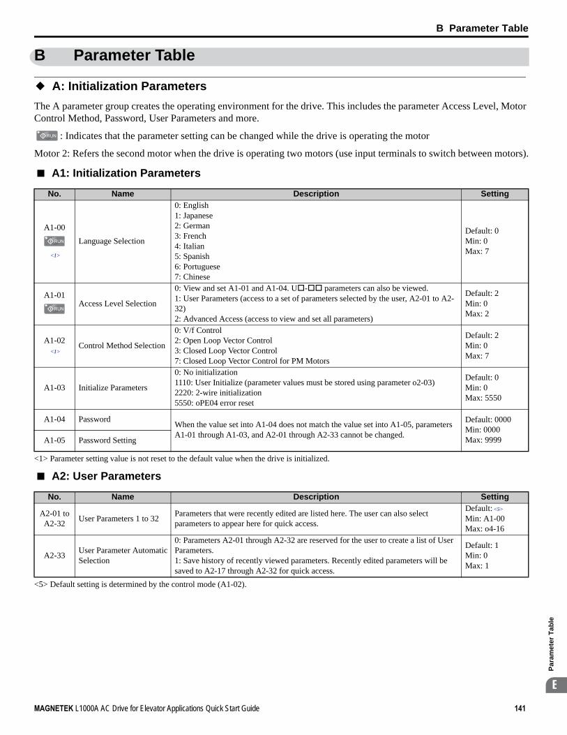
B Parameter Table
MAGNETEK L1000A AC Drive for Elevator Applications Quick Start Guide 141
Par
amet
er T
able
B
B Parameter Table
◆ A: Initialization Parameters
The A parameter group creates the operating environment for the drive. This includes the parameter Access Level, Motor Control Method, Password, User Parameters and more.
: Indicates that the parameter setting can be changed while the drive is operating the motor
Motor 2: Refers the second motor when the drive is operating two motors (use input terminals to switch between motors).
■ A1: Initialization Parameters
■ A2: User Parameters
No. Name Description Setting
A1-00
<1>
<1> Parameter setting value is not reset to the default value when the drive is initialized.
Language Selection
0: English1: Japanese2: German3: French4: Italian5: Spanish6: Portuguese7: Chinese
Default: 0Min: 0Max: 7
A1-01Access Level Selection
0: View and set A1-01 and A1-04. U - parameters can also be viewed.1: User Parameters (access to a set of parameters selected by the user, A2-01 to A2-32)2: Advanced Access (access to view and set all parameters)
Default: 2Min: 0Max: 2
A1-02<1>
Control Method Selection
0: V/f Control2: Open Loop Vector Control3: Closed Loop Vector Control7: Closed Loop Vector Control for PM Motors
Default: 2Min: 0Max: 7
A1-03 Initialize Parameters
0: No initialization1110: User Initialize (parameter values must be stored using parameter o2-03)2220: 2-wire initialization5550: oPE04 error reset
Default: 0Min: 0Max: 5550
A1-04 Password When the value set into A1-04 does not match the value set into A1-05, parameters A1-01 through A1-03, and A2-01 through A2-33 cannot be changed.
Default: 0000Min: 0000Max: 9999A1-05 Password Setting
No. Name Description Setting
A2-01 to A2-32
<5> Default setting is determined by the control mode (A1-02).
User Parameters 1 to 32 Parameters that were recently edited are listed here. The user can also select parameters to appear here for quick access.
Default: <5>
Min: A1-00Max: o4-16
A2-33 User Parameter Automatic Selection
0: Parameters A2-01 through A2-32 are reserved for the user to create a list of User Parameters.1: Save history of recently viewed parameters. Recently edited parameters will be saved to A2-17 through A2-32 for quick access.
Default: 1Min: 0 Max: 1

B Parameter Table
142 MAGNETEK L1000A AC Drive for Elevator Applications Quick Start Guide
◆ b: Application
Application parameters configure the source of the Up/Down command, timer functions, the Dwell function, the Droop Control function, Energy Savings, and a variety of other application-related settings.
■ b1: Operation Mode Selection
■ b2: Magnetic Flux Compensation
■ b4: Delay Timers
No. Name Description Setting
b1-01 Speed Reference Selection
0: Digital operator1: Analog input terminals2: MEMOBUS/Modbus communications3: Option card
Default: 0Min: 0Max: 3
b1-02 Up/Down Command Selection
0: Digital operator1: Digital input terminals2: MEMOBUS/Modbus communications3: Option card
Default: 1Min: 0Max: 3
b1-03 Stopping Method Selection 0: Ramp to stop1: Coast to stop
Default: 0Min: 0Max: 1
b1-06 Digital Input Reading0: Input status is read once and processed immediately (for quick response)1: Input is read twice and processed only if the status is the same in both readings (robust against noisy signals)
Default: 1Min: 0Max: 1
b1-08Up/Down Command Selection while in Programming Mode
0: Up/Down command not accepted while in the Programming Mode.1: Up/Down command accepted while in the Programming Mode.2: Prohibit entering Programming Mode during run.
Default: 0Min: 0Max: 2
b1-14 Phase Order Selection 0: U-V-W1: U-W-V
Default: 0Min: 0Max: 1
No. Name Description Setting
b2-08 Magnetic Flux Compensation Value
Sets the magnetic flux compensation as a percentage of the no-load current value (E2-03).
Default: 0%Min: 0%Max: 1000%
No. Name Description Setting
b4-01 Timer Function On-Delay Time
Used to set the on-delay and off-delay times for a digital timer output (H2- =12). The output is triggered by a digital input programmed to H1- =18)
Default: 0.0 sMin: 0.0 sMax: 3000.0 s
b4-02 Timer Function Off-Delay Time
Default: 0.0 sMin: 0.0 sMax: 3000.0 s

B Parameter Table
MAGNETEK L1000A AC Drive for Elevator Applications Quick Start Guide 143
Par
amet
er T
able
B
■ b6: Dwell Function
■ b7: Droop Control
■ b8: Energy Saving
No. Name Description Setting
b6-01 Dwell Speed at Start
Parameters b6-01 and b6-02 set the speed to hold and the time to maintain that speed at start.Parameters b6-03 and b6-04 set the speed to hold and the time to maintain that speed at stop.
Default: 0.0%Min: 0.0%Max: 100.0%
b6-02 Dwell Time at StartDefault: 0.0 sMin: 0.0 sMax: 10.0 s
b6-03 Dwell Speed at StopDefault: 0.0%Min: 0.0%Max: 100.0%
b6-04 Dwell Time at StopDefault: 0.0 sMin: 0.0 sMax: 10.0 s
No. Name Description Setting
b7-01Droop Control Gain Sets the speed reduction gain applied at a torque reference of 100%. Set as a
percentage of motor base speed.
Default: 0.0%Min: 0.0%Max: 100.0%
b7-02Droop Control Delay Time Used to adjust the responsiveness of Droop Control.
Default: 0.05 sMin: 0.03 sMax: 2.00 s
No. Name Description Setting
b8-01 Energy Saving Control Selection
0: Disabled1: Enabled
Default: 0Min: 0Max: 1
b8-16 Energy Saving Control Constant (Ki)
Enter the Energy Saving value (Ki) as specified on the motor name plate. (for IPM motors only)
Default: 0.10Min: 0.00Max: 2.00
b8-17 Energy Saving Control Constant (Kt)
Enter the Energy Saving value (Kt) as specified on the motor name plate. (for IPM motors only)
Default: 1.00Min: 0.00Max: 2.00

B Parameter Table
144 MAGNETEK L1000A AC Drive for Elevator Applications Quick Start Guide
◆ C: Tuning
C parameters are used to adjust the acceleration and deceleration ramps, jerk settings, slip compensation, torque compensation, and carrier frequency selections.
■ C1: Acceleration and Deceleration Ramps
No. Name Description SettingC1-01
<6> Setting ranges and defaults vary by the setting units determined by parameter o1-03.Refer to Defaults and Setting Ranges by Display Unit Selection (o1-03) on page 187
<8> Setting range value is dependent on parameter C1-10, Accel/Decel Setting Resolution. When C1-10 = 0 (units of 0.01 seconds), the setting range becomes 0.00 to 600.00 seconds.
Acceleration Ramp 1 Sets the ramp to accelerate from 0 to maximum speed.
Default: 1.50 s <6> <8>
Min: 0.00 sMax: 600.00 s <6> <8>
C1-02Deceleration Ramp 1 Sets the ramp to decelerate from maximum speed to 0.
C1-03Acceleration Ramp 2 Sets the ramp to accelerate from 0 to maximum speed.
C1-04Deceleration Ramp 2 Sets the ramp to decelerate from maximum speed to 0.
C1-05 Acceleration Ramp 3 (Motor 2 Accel Time 1) Sets the ramp to accelerate from 0 to maximum speed.
C1-06 Deceleration Ramp 3 (Motor 2 Decel Time 1) Sets the ramp to decelerate from maximum speed to 0.
C1-07 Acceleration Ramp 4 (Motor 2 Accel Time 2) Sets the ramp to accelerate from 0 to maximum speed.
C1-08 Deceleration Ramp 4 (Motor 2 Decel Time 2) Sets the ramp to decelerate from maximum speed to 0.
C1-09 Fast Stop Ramp Sets the ramp for the Fast Stop function.
C1-10 Accel/Decel Setting Resolution
0: 0.01 s unit1: 0.1 s unit
Default: 0Min: 0Max: 1
C1-11 Accel/Decel Switching Speed Sets the speed to switch between accel/decel ramp settings.
Default: 0.0%Min: 0.0%Max: 100.0%
C1-12 Motor 2 Acceleration TimeSets the acceleration time for motor 2. Note: Parameter C1-12 determines the acceleration time for motor 2 as long as d1-27 is not set to 0.00 Hz.
Default: 1.0 s Min: 0.0 s Max: 600.0 s
C1-13 Motor 2 Acceleration Time Sets the deceleration time for motor 2.Default: 1.0 s Min: 0.0 s Max: 600.0 s
C1-15 Inspection Deceleration Ramp Sets the deceleration ramp used for inspection run.
Default: 0.00 s <6> <8>
Min: 0.00 sMax: 2.00 s <6> <8>

B Parameter Table
MAGNETEK L1000A AC Drive for Elevator Applications Quick Start Guide 145
Par
amet
er T
able
B
■ C2: Jerk Settings
■ C3: Slip Compensation
No. Name Description Setting
C2-01
<6> Setting ranges and defaults vary by the setting units determined by parameter o1-03.Refer to Defaults and Setting Ranges by Display Unit Selection (o1-03) on page 187
Jerk at Accel Start
Five different jerk values can be set. They are automatically applied as shown in the figure below.
Default: 0.50 s <6>
Min: 0.00 sMax: 10.00 s <6>
C2-02 Jerk at Accel EndDefault: 0.50 s <6>
Min: 0.00 sMax: 10.00 s <6>
C2-03 Jerk at Decel StartDefault: 0.50 s <6>
Min: 0.00 sMax: 10.00 s <6>
C2-04 Jerk at Decel EndDefault: 0.50 s <6>
Min: 0.00 sMax: 10.00 s <6>
C2-05 Jerk below Leveling Speed Sets the jerk used when the speed reference is lower than the leveling speed settingDefault: 0.50 s <6>
Min: 0.00 sMax: 10.00 s <6>
No. Name Description Setting
C3-01
<5> Default setting is determined by the control mode (A1-02).
Slip Compensation Gain Sets the gain for the motor slip compensation function. Default: 1.0Min: 0.0Max: 2.5
C3-02 Slip Compensation Primary Delay Time Adjusts the slip compensation function delay time.
Default: 2000 msMin: 0 msMax: 10000 ms
C3-03 Slip Compensation Limit Sets an upper limit for the slip compensation function as a percentage of motor rated slip for motor 1 (E2-02).
Default: 200%Min: 0%Max: 250%
C3-04Slip Compensation Selection during Regeneration
0: Disabled.1: Enabled above 6 Hz.2: Enabled whenever slip compensation is possible.
Default: 0Min: 0Max: 2
C3-05 Output Voltage Limit Operation Selection
0: Disabled.1: Enabled. Automatically decreases motor flux when output voltage saturation is reached.
Default: <5>
Min: 0Max: 1
Time
C2-01C2-05
C2-05C2-04
C2-02 C2-03
ONUp/Down commandOutput speed
OFF

B Parameter Table
146 MAGNETEK L1000A AC Drive for Elevator Applications Quick Start Guide
■ C4: Torque Compensation
■ C5: Speed Control Loop Settings
No. Name Description Setting
C4-01
<5> Default setting is determined by the control mode (A1-02).
Torque Compensation Gain
Sets the gain for the automatic torque (voltage) boost function and helps to produce better starting torque.
Default: 1.00Min: 0.00Max: 2.50
C4-02 Torque Compensation Primary Delay Time Sets the torque compensation filter time.
Default: <5>
Min: 0 msMax: 60000 ms
C4-03 Torque Compensation at Forward Start Sets torque compensation at forward start as a percentage of motor torque.
Default: 0.0%Min: 0.0%Max: 200.0%
C4-04 Torque Compensation at Reverse Start Sets torque compensation at reverse start as a percentage of motor torque.
Default: 0.0%Min: -200.0%Max: 0.0%
C4-05 Torque Compensation Time Constant
Sets the time constant for torque compensation at forward start and reverse start (C4-03 and C4-04).
Default: 10 msMin: 0 msMax: 200 ms
No. Name Description Setting
C5-01 Speed Control Loop Proportional Gain 1 Sets the proportional gain 1 of the speed control loop.
Default: <5>
Min: 0.00Max: 300.00
C5-02 Speed Control Loop Integral Time 1 Sets the integral time 1 of the speed control loop.
Default: <5>
Min: 0.000 sMax: 10.000 s
C5-03 Speed Control Loop Proportional Gain 2 Sets the proportional gain 2 of the speed control loop.
Default: <5>
Min: 0.00Max: 300.00
C5-04 Speed Control Loop Integral Time 2 Sets the integral time 2 of the speed control loop.
Default: 0.500 sMin: 0.000 sMax: 10.000 s
C5-06Speed Control Loop Primary Delay Time Constant
Sets the filter time constant for the time from the speed loop to the torque command output.
Default: 0.004 sMin: 0.000 sMax: 0.500 s
C5-07 Speed Control Settings Switching Speed
Sets the speed for switching between proportional gain 1, 2, 3 and integral time 1, 2, 3.
Default: <5>
Min: 0.0%Max: 100.0%
C5-08 Speed Control Loop Integral Limit Sets the speed control loop integral upper limit as a percentage of rated torque.
Default: 400%Min: 0%Max: 400%
C5-13 Speed Control Loop Proportional Gain 3 Sets the proportional gain 3 of the speed control loop.
Default: <5>
Min: 0.00Max: 300.00
C5-14 Speed Control Loop Integral Time 3 Sets the integral time 3 of the speed control loop.
Default: <5>
Min: 0.000 sMax: 10.000 s
C5-16 Speed Control Loop Delay Time during Position Lock
Sets a delay to the torque command output from speed control loop during Position Lock.
Default: 0.000 sMin: 0.000 sMax: 0.500 s
C5-17 Motor Inertia Sets the motor inertia.Default: <4>
Min: 0.0001 kgm2
Max: 600.00 kgm2

B Parameter Table
MAGNETEK L1000A AC Drive for Elevator Applications Quick Start Guide 147
Par
amet
er T
able
B
■ C6: Carrier Frequency
C5-18 Load Inertia Ratio Sets the ratio between the motor and load inertia.Default: 1.0Min: 0.0Max: 6000.0
C5-19 Speed Control Loop Proportional Gain Time during Position Lock
Sets the Speed Control Loop Proportional gain used during Position LockDefault: <5>
Min: 0.00Max: 300.00
C5-20 Speed Control Loop Integral Time during Position Lock
Sets the Speed Control Loop Integral time used during Position Lock.Default:0.100 sMin: 0.000 sMax: 10.000 s
<4> Default setting value varies by the drive model (o2-04).<5> Default setting is determined by the control mode (A1-02).
No. Name Description Setting
C6-03
<4> Default setting value varies by the drive model (o2-04).<39> Available in drive software versions PRG: 7016 and later.
Carrier Frequency Sets the carrier frequency.Default: <4>
Min: 1.0 kHzMax: 15.0 kHz
C6-06 PWM Method
Selects PWM modulation method.0: 2-phase/3-phase conversion1: 2-phase modulation2: 3-phase modulation
Default: 0Min: 0Max: 2
C6-09 Carrier Frequency during Rotational Auto-Tuning
0: Carrier Frequency = 5 kHz1: Setting value for C6-03
Default: 0Min: 0Max: 1
C6-21 Inspection Operation Carrier Frequency
Sets the carrier frequency during Inspection Run.0: Setting value for C6-031: Carrier Frequency = 2 kHz
Default: 1Min: 0Max: 1
C6-23 Carrier Frequency during Initial Motor Pole Search
Sets the carrier frequency when estimating the initial polarity.0: Carrier Frequency = 2 kHz1: Setting value for C6-03
Default: 0Min: 0Max: 1
C6-31<39>
Carrier Frequency during Rescue Operation
Sets the carrier frequency during Rescue Operation.0: C6-03 setting1: 2 kHz
Default: 0Min: 0Max: 1
No. Name Description Setting

B Parameter Table
148 MAGNETEK L1000A AC Drive for Elevator Applications Quick Start Guide
◆ d: Speed References
Speed Reference parameters are used to set the various speed reference values during operation.
■ d1: Speed Reference
No. Name Description Settingd1-01
Speed Reference 1
Sets the Speed reference for the drive when d1-18 is set to 0 or 3. Setting units are determined by parameter o1-03.
Default: 0.00% <6>
Min: 0.00%Max: 100.00% <6>
d1-02Speed Reference 2
d1-03Speed Reference 3
d1-04Speed Reference 4
d1-05Speed Reference 5
d1-06Speed Reference 6
d1-07Speed Reference 7
d1-08Speed Reference 8
d1-18 Speed Reference Selection Mode
Sets the mode of speed reference selection by digital inputs.0: Use multi-speed references (d1-01 to d1-08)1: High speed reference has priority (d1-19 to d1-23, d1-26)2: Leveling speed reference has priority (d1-19 to d1-23, d1-26)3: Use multi-speed references d1-02 to d1-08, no speed selection stops the drive. Drive will stop when all input terminals programmed for speed references (H1- = 3, 4, 5) are open.
Default: 0Min: 0Max: 3
d1-19Nominal Speed Sets the nominal speed reference when d1-18 = 1 or 2.
Default: 100.00% <6>
Min: 0.00%Max: 100.00% <6>
d1-20Intermediate Speed 1 Sets intermediate speed reference 1 when d1-18 = 1 or 2.
Default: 0.00% <6>
Min: 0.00%Max: 100.00% <6>
d1-21Intermediate Speed 2 Sets intermediate speed reference 2 when d1-18 = 1 or 2.
Default: 0.00% <6>
Min: 0.00%Max: 100.00% <6>
d1-22Intermediate Speed 3 Sets intermediate speed reference 3 when d1-18 = 1 or 3.
Default: 0.00% <6>
Min: 0.00%Max: 100.00% <6>
d1-23Releveling Speed Sets speed reference for releveling when d1-18 = 1 or 2.
Default: 0.00% <6>
Min: 0.00%Max: 100.00% <6>
d1-24 Inspection Operation Speed Sets speed reference when inspection operation is enabled.
Default: 50.00% <6>
Min: 0.00%Max: 100.00% <6>

B Parameter Table
MAGNETEK L1000A AC Drive for Elevator Applications Quick Start Guide 149
Par
amet
er T
able
B
■ d6: Field Forcing
d1-25Rescue Operation Speed Sets the speed reference during inspection operation.
Default: 10.00% <6>
Min: 0.00%Max: 100.00% <6>
d1-26Leveling Speed Sets leveling speed reference when d1-18 = 1 or 2.
Default: 8.00% <6>
Min: 0.00%Max: 100.00% <6>
d1-27 Motor 2 Speed Reference
Sets the speed reference for motor 2. Note: 1. If set to 0.00, the drive will control motor 1 instead.2. When using motor 2, be sure that the accel/decel times are set in parameters C1-12 and C1-13.
Default: 0.00 HzMin: 0.00 HzMax: 120.00 Hz
d1-28 Leveling Speed Detection Level
Used when d1-18 = 0 or 3. If the speed reference selected is lower than d1-28, then the drive uses the leveling speed as the speed reference.
Default: 0.0%Min: 0.0%Max: 100.0%
d1-29 Inspection Speed Detection Level
Used when d1-18 = 0 or 3. If the speed reference selected is higher than d1-28 but lower or equal to d1-29, then the drive uses inspection speed as the speed reference.
Default: 0.0%Min: 0.0%Max: 100.0%
<6> Setting ranges and defaults vary by the setting units determined by parameter o1-03.Refer to Defaults and Setting Ranges by Display Unit Selection (o1-03) on page 187
No. Name Description Setting
d6-03 Field Forcing Selection 0: Disabled1: Enabled
Default: 0Min: 0Max: 1
d6-06 Field Forcing LimitSets the upper limit of the excitation current command during magnetic field forcing. A setting of 100% is equal to motor no-load current. Disabled only during DC Injection Braking.
Default: 400%Min: 100%Max: 400%
No. Name Description Setting

B Parameter Table
150 MAGNETEK L1000A AC Drive for Elevator Applications Quick Start Guide
◆ E: Motor Parameters
■ E1: V/f Pattern
No. Name Description Setting
E1-01
<2> Default setting is dependent on the control mode (A1-02) and the drive model (o2-04).<5> Default setting is determined by the control mode (A1-02).<9> Values shown here are for 200 V class drives. The default is 400 V when using a 400 V class drive.<11> Parameter is ignored when E1-11 and E1-12 are set to 0.0.<13> When E1-13 (Base Voltage) is set to 0.0, output voltage is controlled with E1-05 (Maximum Voltage) = E1-13. When Auto-Tuning is
performed, E1-05 and E1-13 are automatically set to the same value.<23> Setting range depends on the type of motor being used. CLV allows a setting range of 10.0 to 120.0 Hz, while CLV/PM allows a setting range
of 4.0 to 120.0 Hz.
Input Voltage Setting
This parameter must be set to the power supply voltage.WARNING! Electrical Shock Hazard. Drive input voltage (not motor voltage) must be set in E1-01 for the protective features of the drive to function properly. Failure to do so may result in equipment damage and/or death or personal injury.
Default: 230 V <9>
Min: 155 VMax: 255 V <9>
E1-03 V/f Pattern Selection F: Custom V/f, E1-04 through E1-13 settings define the V/f patternDefault: FMin: –Max: F
E1-04 Maximum Output Frequency
To set linear V/f characteristics, set the same values for E1-07 and E1-09. In this case, the setting for E1-08 will be disregarded. Ensure that the five frequencies are set according to these rules:E1-09 ≤ E1-07 < E1-06 ≤ Ε1−11 ≤ E1-04Note that if E1-11 = 0, then both E1-11 and E1-12 are disabled, and the above conditions do not apply.
Note: Some parameters may not be available depending on the control mode.• E1-07, E1-08 and E-10 are available only in the V/f control and Open Loop Vector
control modes.• E1-11, E1-12 and E-13 are available only in the V/f control and Closed Loop
Vector control modes.
Default: <5>
Min: <23>
Max: 120.0 Hz
E1-05 Maximum Voltage
Default: 230.0 V <9>
Min: 0.0 VMax: 255.0 V <9>
E1-06 Base FrequencyDefault: <5>
Min: 0.0 HzMax: 120.0 Hz
E1-07 Middle Output FrequencyDefault: 3.0 HzMin: 0.0 HzMax: 120.0 Hz
E1-08 Middle Output Frequency Voltage
Default: <2> <9>
Min: 0.0 VMax: 255.0 V <9>
E1-09 Minimum Output Frequency
Default: <5>
Min: 0.0 HzMax: 120.0 Hz
E1-10 Minimum Output Frequency Voltage
Default: <2> <9>
Min: 0.0 VMax: 255.0 V <9>
E1-11<11>
Middle Output Frequency 2
Default: 0.0 HzMin: 0.0 HzMax: 120.0 Hz
E1-12<11>
Middle Output Frequency Voltage 2
Default: 0.0 V <9>
Min: 0.0 VMax: 255.0 V <9>
E1-13<13>
Base VoltageDefault: 0.0 V <9>
Min: 0.0 VMax: 255.0 V <9>
Output Voltage (V)
Frequency (Hz)
E1-05E1-12
E1-13
E1-08
E1-10
E1-09 E1-07 E1-06 E1-11 E1-04

B Parameter Table
MAGNETEK L1000A AC Drive for Elevator Applications Quick Start Guide 151
Par
amet
er T
able
B
■ E2: Motor Parameters
No. Name Description Setting
E2-01
<4> Default setting value varies by the drive model (o2-04).<10> The display resolution depends on the rated output power of the drive. Models CIMR-LU2A0008 to 2A0033 and CIMR-LU4A0005 to
4A0018 display values in 0.01 A units, while models CIMR-LU2A0047 to 2A0415 and CIMR-LU4A0024 to 4A0260 display values in 0.1 A units.
Motor Rated Current Sets the motor nameplate full load current in Amps. Automatically set during Auto-Tuning.
Default: <4>
Min: 10% of drive rated currentMax: 200% of drive rated current <10>
E2-02 Motor Rated Slip Sets the motor rated slip. Automatically set during Auto-Tuning.Default: <4>
Min: 0.00 HzMax: 20.00 Hz
E2-03 Motor No-Load Current Sets the no-load current for the motor. Automatically set during Auto-Tuning.Default: <4>
Min: 0 AMax: E2-01 <10>
E2-04 Number of Motor Poles Sets the number of motor poles. Automatically set during Auto-Tuning.Default: 4Min: 2Max: 48
E2-05 Motor Line-to-Line Resistance Sets the phase-to-phase motor resistance. Automatically set during Auto-Tuning.
Default: <4>
Min: 0.000 ΩMax: 65.000 Ω
E2-06 Motor Leakage Inductance Sets the voltage drop due to motor leakage inductance as a percentage of motor rated voltage. Automatically set during Auto-Tuning.
Default: <4>
Min: 0.0%Max: 40.0%
E2-07 Motor Iron-Core Saturation Coefficient 1
Sets the motor iron saturation coefficient at 50% of magnetic flux. Automatically set during Auto-Tuning.
Default: 0.50Min: 0.00Max: 0.50
E2-08 Motor Iron-Core Saturation Coefficient 2
Sets the motor iron saturation coefficient at 75% of magnetic flux. Automatically set during Auto-Tuning.
Default: 0.75Min: E2-07Max: 0.75
E2-09 Motor Mechanical Loss Sets the motor mechanical loss as a percentage of motor rated power (kW).Default: 0.0%Min: 0.0%Max: 10.0%
E2-10 Motor Iron Loss for Torque Compensation Sets the motor iron loss.
Default: <4>
Min: 0 WMax: 65535 W
E2-11 Motor Rated Power Sets the motor rated power in kilowatts (1 HP = 0.746 kW). Automatically set during Auto-Tuning.
Default: <4>
Min: 0.00 kWMax: 650.00 kW

B Parameter Table
152 MAGNETEK L1000A AC Drive for Elevator Applications Quick Start Guide
■ E3: V/f Pattern for Motor 2
These parameters are hidden when a PM motor control mode has been selected for motor 1 (A1-02 = 7).
■ E4: Motor 2 Parameters
These parameters are hidden when a PM motor control mode has been selected for motor 1 (A1-02 = 7).
No. Name Description Setting
E3-04
<4> Default setting value is dependent on the drive model (o2-04).<9> Values shown here are for 200 V class drives. Double the value when using a 400 V class drive.
Motor 2 Maximum Output Frequency
These parameters are only applicable when E1-03 is set to F.To set linear V/f characteristics, set the same values for E3-07 and E3-09. In this case, the setting for E3-08 will be disregarded. Ensure that the three frequencies are set according to these rules or an oPE10 fault will occur:E3-09 ≤ E3-07 < E3-06 ≤ E3-04
Default: 60.0 HzMin: 10.0 HzMax: 120.0 Hz
E3-05 Motor 2 Maximum VoltageDefault: 230.0 VMin: 0.0 VMax: 255.0 V <9>
E3-06 Motor 2 Base FrequencyDefault: 60.0 HzMin: 0.0 HzMax: 120.0 Hz
E3-07 Motor 2 Mid Output Frequency
Default: 3.0 HzMin: 0.0 HzMax: 120.0 Hz
E3-08 Motor 2 Mid Output Frequency Voltage
Default: <4>
Min: 0.0 VMax: 255.0 V <9>
E3-09 Motor 2 Minimum Output Frequency
Default: 1.5 HzMin: 0.0 HzMax: 120.0 Hz
E3-10 Motor 2 Minimum Output Frequency Voltage
Default: <4>
Min: 0.0 VMax: 255.0 V <9>
No. Name Description Setting
E4-01
<4> Default setting value is dependent on the drive model (o2-04).<10> The display resolution depends on the rated output power of the drive. Models CIMR-LU2A0008 to 2A0033 and CIMR-LU4A0005 to
4A0018 display values in 0.01 A units, while models CIMR-LU2A0047 to 2A0415 and CIMR-LU4A0024 to 4A0260 display values in 0.1 A units.
Motor 2 Rated Current Sets the full load current for motor 2. Automatically set during Auto-Tuning.
Default: <4>
Min: 10% of drive rated currentMax: 200% of drive rated current <10>
E4-02 Motor 2 Rated Slip Sets the rated slip for motor 2. Automatically set during Auto-Tuning.Default: <4>
Min: 0.00 HzMin: 20.00 Hz
E4-03 Motor 2 Rated No-Load Current Sets the no-load current for motor 2. Automatically set during Auto-Tuning.
Default: <4>
Min: 0 AMin: [E4-01] <10>
E4-04 Motor 2 Motor Poles Sets the number of poles of motor 2. Automatically set during Auto-Tuning.Default: 4Min: 2Max: 48
E4-05 Motor 2 Line-to-Line Resistance Sets the phase-to-phase resistance for motor 2. Automatically set during Auto-Tuning.
Default: <4>
Min: 0.000 ΩMax: 65.000 Ω
E4-06 Motor 2 Leakage Inductance
Sets the voltage drop for motor 2 due to motor leakage inductance as a percentage of rated voltage. Automatically set during Auto-Tuning.
Default: <4>
Min: 0.0%Max: 40.0%
E3-05
E3-08
E3-10
E3-09 E3-07 E3-04
Output Voltage (V)
Frequency (Hz)

B Parameter Table
MAGNETEK L1000A AC Drive for Elevator Applications Quick Start Guide 153
Par
amet
er T
able
B
■ E5: PM Motor Settings
No. Name Description Setting
E5-02<1>
<1> Parameter setting value is not reset to the default value when the drive is initialized.<4> Default setting value is determined by the drive model (o2-04).<10> The display resolution depends on the rated output power of the drive. Models CIMR-LU2A0008 to 2A0033 and CIMR-LU4A0005 to
4A0018 display values in 0.01 A units, while models CIMR-LU2A0047 to 2A0415 and CIMR-LU4A0024 to 4A0260 display values in 0.1 A units.
Motor Rated Power Sets the rated capacity of the motor.Default: <4>
Min: 0.10 kWMax: 650.00 kW
E5-03<1>
Motor Rated Current Sets the motor rated current.
Default: <4>
Min: 10% of drive rated currentMax: 200% of drive rated current <10>
E5-04<1>
Number of Motor Poles Sets the number of motor poles.Default: 12Min: 2Max: 48
E5-05<1>
Motor Stator Resistance(Single Phase) Sets the stator resistance (1 phase value).
Default: <4>
Min: 0.000 ΩMax: 65.000 Ω
E5-06<1>
Motor d-Axis Inductance Sets the d-axis inductance.Default: <4>
Min: 0.00 mHMax: 600.00 mH
E5-07<1>
Motor q-Axis Inductance Sets the q-axis inductance.Default: <4>
Min: 0.00 mHMax: 600.00 mH
E5-09<1>
Motor Induction Voltage Constant 1
Sets the induced phase peak voltage in units of 0.1 mV (rad/s) [electrical angle]. When setting this parameter, E5-24 should be set to 0.0.
Default: <4>
Min: 0.0 mV/(rad/s)Max: 6500.0 mV/(rad/s)
E5-11 Encoder Offset Sets the offset between the rotor magnetic axis and the encoder zero position. Set during Encoder Offset Tuning.
Default: 0.0 degMin: -180 degMax: 180 deg
E5-24 Motor Induction Voltage Constant 2
Sets the induced phase-to-phase rms voltage in units of 0.1 mV/(r/min) [mechanical angle]. When setting this parameter, E5-09 should be set to 0.0.
Default:0.0 mV/(r/min)
Min: 0.0 mV/(r/min)
Max: 6500.0 mV/(r/min)

B Parameter Table
154 MAGNETEK L1000A AC Drive for Elevator Applications Quick Start Guide
◆ F: Option Settings
F parameters are used to program the drive for Encoder and PG feedback from the motor and to function with option cards.
■ F1: PG Speed Control Card
No. Name Description Setting
F1-01 Encoder 1 Resolution Sets the encoder resolution (number of pulses per revolution)
Default: <5>
Min: 1 pprMax: 60000 ppr <34>
F1-02 Operation Selection at PG Open Circuit (PGo)
0: Ramp to stop. Decelerate to stop using the deceleration ramp in C1-02.1: Coast to stop.2: Fast Stop. Decelerate to stop using the deceleration ramp in C1-09.3: Alarm only.
Default: 1Min: 0Max: 3
F1-03 Operation Selection at Overspeed (oS)
0: Ramp to stop. Decelerate to stop using the deceleration ramp in C1-02.1: Coast to stop.2: Fast Stop. Decelerate to stop using the deceleration ramp in C1-09.3: Alarm only.
Default: 1Min: 0Max: 3
F1-04 Operation Selection at Deviation
0: Ramp to stop. Decelerate to stop using the deceleration ramp in C1-02.1: Coast to stop.2: Fast Stop. Decelerate to stop using the deceleration ramp in C1-09.3: Alarm only.
Default: 3Min: 0Max: 3
F1-05 Encoder 1 Rotation Direction Selection
0: A phase leads B in up direction1: B phase leads A in up direction
Default: <5>
Min: 0Max: 1
F1-06 PG 1 Pulse Monitor Output Division Ratio
Sets the division ratio for the pulse monitor used of the PG option card installed to connector CN5-C. By setting “xyz”, the division ratio becomes = [(1 + x) / yz]. If only using the A pulse for one track input, then the input ratio will be 1:1, regardless of what F1-06 is set to.
Default: 1Min: 1Max: 132
F1-08 Overspeed Detection Level Sets the overspeed detection level as a percentage of the maximum output frequency.Default: 115%Min: 0%Max: 120%
F1-09 Overspeed Detection Delay Time Sets the time in seconds for an overspeed situation to trigger a fault (oS).
Default: 0.0 sMin: 0.0 sMax: 2.0 s
F1-10 Excessive Speed Deviation Detection Level
Sets the speed deviation detection level as a percentage of the maximum output frequency.
Default: 10%Min: 0%Max: 50%
F1-11 Excessive Speed Deviation Detection Delay Time Sets the time in seconds for a speed deviation situation to trigger a fault (dEv).
Default: 0.5 sMin: 0.0 sMax: 10.0 s
F1-14 PG Open-Circuit Detection Time Sets the time required to trigger a PG Open fault (PGo).
Default: 2.0 sMin: 0.0 sMax: 10.0 s
F1-18 dv3 Detection Selection0: Disabledn: Sets the number of dv3 situations that may be detected before triggering an actual dv3 fault.
Default: 10Min: 0Max: 10
F1-19 dv4 Detection Selection 0: Disabledn: Number of pulses that the A and B pulse are reversed that triggers dv4 detection.
Default: 128Min: 0Max: 5000
F1-20 PG Option Card Disconnect Detection 1
0: Disabled1: Enabled
Default: 1Min: 0Max: 1

B Parameter Table
MAGNETEK L1000A AC Drive for Elevator Applications Quick Start Guide 155
Par
amet
er T
able
B
■ F3: Digital Input Card (DI-A3)
■ F4: Analog Monitor Card (AO-A3)
F1-29 dEv Detection Condition Selection
Selects when DEV is active.0: After speed reference, soft starter output and motor speed have matched once.1: After speed reference and soft starter output have matched once.2: Always during Run
Default: 2Min: 0Max: 2
F1-50<39>
Encoder Selection
Selects the encoder connected the PG-F3 option.0: EnDat 2.1/01, 2.2/01 Serial Communication + Sin/Cos1: EnDat 2.2/22 Serial Communication2: Hiperface
Default: 0Min: 0Max: 2
F1-51 PGoH Detection Level Sets the level for detecting PG Hardware Fault (PGoH). Available when F1-20 = 1Default: 80%Min: 1%Max: 100%
F1-52<39>
Communication Speed of Serial Encoder Selection
Selects the communication speed between the PG-F3 option and serial encoder.0: 1M bps/9600 bps1: 500k bps/19200 bps2: 1M bps/38400 bps3: 1M bps/38400 bps
Default: 0Min: 0Max: 3
F1-63 PG-E3 R Track Selection 0: Disabled1: Enabled
Default: 0Min: 0Max: 1
<5> Default setting is determined by the control mode (A1-02).<34> Setting range is 1 to 15000 ppr when the drive is set for CLV/PM.<39> Available in drive software versions PRG: 7016 and later.
No. Name Description Setting
F3-01 DI-A3 Option Card Input Selection
0: BCD, 1% units1: BCD, 0.1% units2: BCD, 0.01% units3: BCD, 1 Hz units4: BCD, 0.1 Hz units5: BCD, 0.01 Hz units6: BCD customized setting (5 digit), 0.02 Hz units7: Binary inputThe unit and the setting range are determined by F3-03.F3-03 = 0: 255/100% (-255 to +255)F3-03 = 1: 40961/100% (-4095 to +4095)F3-03 = 2: 30000/100% (-33000 to +33000)When the digital operator units are set to be displayed in Hertz or user-set units (o1-03 = 2 or 3), the units for F3-01 are determined by parameter o1-03.
Default: 0Min: 0Max: 7
F3-03 DI-A3 Option Card Data Length Selection
0: 8 bit1: 12 bit2: 16 bit
Default: 2Min: 0Max: 2
No. Name Description Setting
F4-01 Terminal V1 Function Selection
Sets the monitor signal for output from terminal V1. Set this parameter to the last three digits of the desired U - monitor. Some U parameters are available only in certain control modes.
Default: 102Min: 000Max: 999
F4-02Terminal V1 Gain Sets the gain for voltage output via terminal V1.
Default: 100.0%Min: -999.9%Max: 999.9%
F4-03 Terminal V2 Function Selection
Sets the monitor signal for output from terminal V2. Set this parameter to the last three digits of the desired U - monitor. Some U parameters are available only in certain control modes.
Default: 103Min: 000Max: 999
F4-04Terminal V2 Gain Sets the gain for voltage output via terminal V2.
Default: 50.0%Min: -999.9%Max: 999.9%
No. Name Description Setting

B Parameter Table
156 MAGNETEK L1000A AC Drive for Elevator Applications Quick Start Guide
■ F5: Digital Output Card (DO-A3)
F4-05Terminal V1 Bias Sets the amount of bias added to the voltage output via terminal V1.
Default: 0.0%Min: -999.9%Max: 999.9%
F4-06Terminal V2 Bias Sets the amount of bias added to the voltage output via terminal V2.
Default: 0.0%Min: -999.9%Max: 999.9%
F4-07 Terminal V1 Signal Level Selection
0: 0 to 10 V1: -10 to 10 V
Default: 1Min: 0Max: 1
F4-08 Terminal V2 Signal Level Selection
Default: 1Min: 0Max: 1
No. Name Description Setting
F5-01 Terminal P1-PC Output Selection
Sets the function for contact output terminals M1-M2, M3-M4, and photocoupler output terminals P1 through P6.
Default: 0Min: 0Max: 161
F5-02 Terminal P2-PC Output Selection
Default: 1Min: 0Max: 161
F5-03 Terminal P3-PC Output Selection
Default: 2Min: 0Max: 161
F5-04 Terminal P4-PC Output Selection
Default: 4Min: 0Max: 161
F5-05 Terminal P5-PC Output Selection
Default: 6Min: 0Max: 161
F5-06 Terminal P6-PC Output Selection
Default: 37Min: 0Max: 161
F5-07 Terminal M1-M2 Output Selection
Default: FMin: 0Max: 161
F5-08 Terminal M3-M4 Output Selection
Default: FMin: 0Max: 161
F5-09 DO-A3 Output Mode Selection
0: Output terminals are each assigned separate output functions.1: Binary code output2: Use output terminal functions selected by parameters F5-01 through F5-08.
Default: 0Min: 0Max: 2
No. Name Description Setting

B Parameter Table
MAGNETEK L1000A AC Drive for Elevator Applications Quick Start Guide 157
Par
amet
er T
able
B
■ F6: Communication Option Card
For more details on a specific option card, refer to the instruction manual for the option card.
No. Name Description Setting
F6-01
<1> Parameter setting value is not reset to the default value when the drive is initialized.
Operation Selection after Communications Error
0: Ramp to stop. Decelerate to stop using the deceleration ramp in C1-02.1: Coast to stop.2: Fast Stop. Decelerate to stop using the deceleration ramp in C1-09.3: Alarm only.
Default: 1Min: 0Max: 3
F6-02External Fault from Communication Option Detection Selection
0: Always detected 1: Detection during run only
Default: 0Min: 0Max: 1
F6-03External Fault from Communication Option Operation Selection
0: Ramp to stop. Decelerate to stop using the deceleration ramp in C1-02.1: Coast to stop.2: Fast Stop. Decelerate to stop using the deceleration ramp in C1-09.3: Alarm only.
Default: 1Min: 0Max: 3
F6-04 bUS Error Detection Time Sets the delay time for error detection if a bus error occurs.Default: 2.0 sMin: 0.0 sMax: 5.0 s
F6-06Torque Limit Selection from Communications Option
0: Disabled. Torque limit from option card disabled.1: Enabled. Torque limit from option card enabled.
Default: 0Min: 0Max: 1
F6-08<1>
Reset Communication Parameter
0: Communication-related parameters (F6- ) are not reset when the drive is initialized using A1-03.1: Reset all communication-related parameters (F6- ) when the drive is initialized using A1-03.
Default: 0Min: 0Max: 1
F6-35 CANopen Node ID Sets the node address.Default: 0Min: 0Max: 126
F6-36 CANopen Communication Speed
0: Auto-detection1: 10 kbps 2: 20 kbps 3: 50 kbps 4: 125 kbps 5: 250 kbps 6: 500 kbps 7: 800 kbps 8: 1 Mbps
Default: 6Min: 0Max: 8

B Parameter Table
158 MAGNETEK L1000A AC Drive for Elevator Applications Quick Start Guide
◆ H: Multi-Function Terminals
H parameters assign functions to the multi-function input and output terminals.
■ H1: Multi-Function Digital Inputs
No. Name Description Setting
H1-03
<19> With the speed reference priority d1-18 is set to 0 or 3, the default settings for parameters H1-03 to H1-07 governing input terminals S3 to S7 are: 24, 14, 3, 4, and 5 respectively. When d1-18 is set to 1 or 2, the default settings for H1-03 to H1-07 become 50, 54, 51, 53, and F respectively.
Terminal S3 Function Selection
Assigns a function to the multi-function digital inputs.Refer to page 158 to page 159 for a description of setting values.Note: Unused terminals should be set to F.
Default: <19>
Min: 3Max: 79
H1-04 Terminal S4 Function Selection
Default: <19>
Min: 3Max: 79
H1-05 Terminal S5 Function Selection
Default: <19>
Min: 3Max: 79
H1-06 Terminal S6 Function Selection
Default: <19>
Min: 3Max: 79
H1-07 Terminal S7 Function Selection
Default: <19>
Min: 3Max: 79
H1-08 Terminal S8 Function Selection
Default: FMin: 3Max: 79
H1 Multi-Function Digital Input SettingsH1-Setting Function Description
3 Multi-Step Speed Reference 1 When input terminals are set to Multi-Step Speed References 1 through 3, switching combinations of those terminals will create a multi-step speed sequence using the speed references set in d1-01 through d1-08.
4 Multi-Step Speed Reference 25 Multi-Step Speed Reference 3
6 Jog reference selection
Closed: Jog frequency reference (d1-17) selected.The Jog frequency can be used when the speed reference selection is not assigned to input terminals (b1-01 ≠ 1) and the speed reference priority is set to use the multi-step speed reference (d1-18 = 0 or 3).
7 Accel/decel Ramp Selection 1
Used to switch between accel/decel ramp 1 (set in C1-01, C1-02) and accel/decel ramp 2 (set in C1-03, C1-04).When combined with another input terminal set for "Accel/Decel ramp 2" (H1- = 1A), the drive can also switch between accel/decel ramp 3 (set in C1-05, C1-06) and accel/decel ramp 4 (set in C1-07, C1-08).
8 Baseblock Command (N.O.) Closed: No drive output9 Baseblock Command (N.C.) Open: No drive output
F Not Used (Through Mode)Select this setting when the terminal is not used or when using the terminal in the pass-through mode. The terminal does not trigger a drive function but can be used as digital input for the controller the drive is connected to.
14 Fault Reset Closed: Resets faults if the cause is cleared and the Up/Down command is removed.15 Fast Stop (N.O.) Closed: Decelerates to stop at the Fast Stop ramp set to C1-09.
16 Motor 2 Selection Open: Motor 1(E1- , E3- )Closed: Motor 2 (E2- , E4- )
17 Fast Stop (N.C.) Open: Decelerates to stop at the Fast Stop ramp set to C1-09.
18 Timer Function Input Triggers the timer set up by parameters b4-01 and b4-02. Must be set in conjunction with the timer function output (H2- = 12).

B Parameter Table
MAGNETEK L1000A AC Drive for Elevator Applications Quick Start Guide 159
Par
amet
er T
able
B
■ H2: Multi-Function Digital Outputs
1A Accel/decel Ramp Selection 2 Used in conjunction with an input terminal set for “Accel/decel ramp selection 1” (H1- = 7), and allows the drive to switch between accel/decel ramp 3 and 4.
20 to 2F External Fault
20: N.O., Always detected, ramp to stop21: N.C., Always detected, ramp to stop22: N.O., During run, ramp to stop23: N.C., During run, ramp to stop24: N.O., Always detected, coast to stop25: N.C., Always detected, coast to stop26: N.O., During run, coast to stop27: N.C., During run, coast to stop28: N.O., Always detected, Fast Stop29: N.C., Always detected, Fast Stop2A: N.O., During run, Fast Stop2B: N.C., During run, Fast Stop2C: N.O., Always detected, alarm only (continue running)2D: N.C., Always detected, alarm only (continue running)2E: N.O., During run, alarm only (continue running)2F: N.C., During run, alarm only (continue running)
50 Nominal Speed Closed: Activates the nominal speed (d1-19). 51 Intermediate Speed Closed: Activates the Intermediate Speed (d1-20).52 Releveling Speed Closed: Activates the Releveling Speed (d1-23).53 Leveling Speed Closed: Activates the Leveling Speed (d1-26).54 Inspection Operation Closed: Activates Inspection operation using the speed set in d1-24.55 Rescue Operation Closed: Activates rescue operation.56 Motor Contactor Feedback Used for motor contactor supervision and fault detection.57 High Speed Limit (Up) Closed: Uses the leveling speed as the maximum speed when going up.58 High Speed Limit (Down) Closed: Uses the leveling speed as the maximum speed when going down.5C Floor Sensor Closed: Initiate Direct Landing (S5-10 = 1)
67 Communications Test Mode Tests the MEMOBUS/Modbus RS-485/422 interface. Displays “PASS” if the test completes successfully.
79 Brake Feedback Used for brake supervision and detection of incorrect operation.
No. Name Description Setting
H2-01 Terminals M1-M2 Function Selection (relay)
Refer to H2 Multi-Function Digital Output Settings on page 160 for a description of setting values.
Default: 50Min: 0Max: 161
H2-02 Terminals M3-M4 Function Selection (relay)
Default: 51Min: 0Max: 161
H2-03 Terminals M5-M6 Function Selection (relay)
Default: 6Min: 0Max: 161
H2-04 Terminal P1-C1 Function Selection (photocoupler)
Default: 37Min: 0Max: 161
H2-05 Terminal P2-C2 Function Selection (photocoupler)
Default: FMin: 0Max: 161
H1 Multi-Function Digital Input SettingsH1-Setting Function Description

B Parameter Table
160 MAGNETEK L1000A AC Drive for Elevator Applications Quick Start Guide
H2 Multi-Function Digital Output SettingsH2-Setting Function Description
0 During Run Closed: An Up/Down command is active or voltage is output.
1 Zero Speed
Open: Output speed is greater than the value of E1-09 (Minimum Output Frequency) or S1-01 (Zero Speed Level at Stop).Closed: Output frequency is less than or equal to the value of E1-09 (Minimum Output Frequency) or S1-01 (Zero Speed Level at Stop).
2 Speed Agree 1 Closed: Output speed equals the speed reference (plus or minus the hysteresis set to L4-02).3 User-set Speed Agree 1 Closed: Output speed and speed reference equal L4-01 (plus or minus the hysteresis set to L4-02).4 Speed Detection 1 Closed: Output speed is less than or equal to the value in L4-01 with hysteresis determined by L4-02.5 Speed Detection 2 Closed: Output speed is greater than or equal to the value in L4-01 with hysteresis determined by L4-02.6 Drive Ready (READY) Closed: Power up is complete and the drive is ready to accept an Up/Down command.7 DC Bus Undervoltage Closed: DC bus voltage is below the Uv trip level set in L2-05.8 During Baseblock (N.O.) Closed: Drive has entered the baseblock state (no output voltage).
9 Speed Reference Source Open: The speed reference is supplied by an external reference (set in b1-01).Closed: Digital operator supplies the speed reference.
A Up/Down Command Source Open: The Up/Down command is supplied by an external reference (set in b1-02).Closed: Digital operator supplies the Up/Down command.
B Torque Detection 1 Closed: An overtorque or undertorque situation has been detected.E Fault Closed: Fault occurred. (excluding CPF00 and CPF01)F Not used (Through Mode) Set this value when the terminal is not used or when using the terminal in the pass-through mode.10 Minor Fault Closed: An alarm has been triggered, or the IGBTs have reached 90% of their expected life span.
11 Fault Reset Command Active
Closed: The drive has received a reset command from the multi-function input terminals or from serial network, or the digital operator’s RESET key has been pressed.
12 Timer Output Closed: Timer output.13 Speed Agree 2 Closed: When drive output frequency equals the speed reference ±L4-04.14 User-set Speed Agree 2 Closed: When the drive output speed is equal to the value in L4-03 ±L4-04.15 Speed Detection 3 Closed: When the drive output speed is less than or equal to the value in L4-03 ±L4-04.16 Speed Detection 4 Closed: When the output speed is greater than or equal to the value in L4-03 ±L4-04.18 Torque Detection 2 Closed: Overtorque or undertorque has been detected.1A During Down Direction Closed: Drive is running in the down direction.1B During Baseblock 2 (N.C.) Open: Drive has entered the baseblock state (no output voltage).
1C Motor 2 Selection Open: Motor 1 is selectedClosed: Motor 2 is selected
1D During Regeneration Closed: Motor is operated in regenerative mode.1E Reset Enabled Closed: An automatic reset is performed
1F Motor Overload Alarm (oL1) Closed: oL1 is at 90% of its trip point or greater. An oH3 situation also triggers this alarm.
20 Drive Overheat Pre-alarm (oH) Closed: Heatsink temperature exceeds the parameter L8-02 value.
2F Maintenance Period Closed: Cooling fan, electrolytic capacitors, IGBTs, or the soft charge bypass relay may require maintenance.
30 During Torque Limit Closed: When the torque limit has been reached.
33 Within Position Lock Bandwidth Closed: Position deviation is within the Position Lock Bandwidth.
37 During Frequency OutputOpen: No frequency output from drive when stopped with baseblock, stopped with DC injection braking during initial excitation, or stopped with short circuit braking.Closed: Drive is outputting a frequency.
47 Input Phase Loss Closed: Input phase loss has occurredOpen: Normal operation (no phase loss detected)
4E Braking Transistor Fault (rr) Closed: The built-in dynamic braking transistor failed.Note: This function is not available in models CIMR-LU2A0145 to 2A0415, 4A0075 to 4A0216.

B Parameter Table
MAGNETEK L1000A AC Drive for Elevator Applications Quick Start Guide 161
Par
amet
er T
able
B
■ H3: Multi-Function Analog Inputs
50 Brake Control Close: Release brakeOpen: Apply brake
51 Output Contactor Control Closed: Close output contactor52 Door Zone Reached Closed: Indicates that the door zone has been reached.
53 Not Zero Speed Closed: Speed is greater than the zero speed level set to S1-01Open: Operating at zero speed level
54 Light Load Direction Closed: Light load direction is upOpen: Light load direction is down
55 Light Load Direction Detection Status
Closed: Ready for Light Load Direction SearchOpen: Light Load Detection in progress
58 Safe Disable Status Closed: Safe Disable terminals H1-HC and H2-HC are open, drive is in a baseblock stateOpen: Safe Disable terminals H1-HC and H2-HC are closed (normal operation)
60 Internal Cooling Fan Alarm Closed: Internal cooling fan alarm61 Motor Pole Search Status Closed: Motor pole search successful
100 to 161 Function 0 to 61 with Inverse Output
Inverts the output switching of the multi-function output functions.Sets the last two digits of 1 to reverse the output signal of that specific function.
No. Name Description Setting
H3-01 Terminal A1 Signal Level Selection
0: 0 to 10 V1: –10 to 10 V
Default: 0Min: 0Max: 1
H3-02 Terminal A1 Function Selection Sets the function of terminal A1.
Default: 0Min: 0Max: 1F
H3-03Terminal A1 Gain Setting Sets the level of the input value selected in H3-02 when 10 V is input at terminal A1.
Default: 100.0%Min: -999.9%Max: 999.9%
H3-04Terminal A1 Bias Setting Sets the level of the input value selected in H3-02 when 0 V is input at terminal A1.
Default: 0.0%Min: -999.9%Max: 999.9%
H3-09 Terminal A2 Signal Level Selection
0: 0 to 10 V1: –10 to 10 VNote: Use DIP switch S1 to set input terminal A2 for a current or a voltage input signal.
Default: 0Min: 0Max: 0
H3-10 Terminal A2 Function Selection Sets the function of terminal A2.
Default: 0Min: 0Max: 1F
H3-11Terminal A2 Gain Setting Sets the level of the input value selected in H3-10 when 10 V is input at terminal A2.
Default: 100.0%Min: -999.9%Max: 999.9%
H3-12Terminal A2 Bias Setting Sets the level of the input value selected in H3-10 when 0 V is input at terminal A2.
Default: 0.0%Min: -999.9%Max: 999.9%
H3-13 Analog Input Filter Time Constant
Sets a primary delay filter time constant for terminals A1 and A2. Used for noise filtering.
Default: 0.03 sMin: 0.00 sMax: 2.00 s
H3-16 Offset for Terminal A1 Applies an offset to analog input A1. Can be used for zero adjustment of the analog input.
Default: 0Min: -500Max: 500
H3-17 Offset for Terminal A2 Applies an offset to analog input A2. Can be used for zero adjustment of the analog input.
Default: 0Min: -500Max: 500
H2 Multi-Function Digital Output SettingsH2-Setting Function Description

B Parameter Table
162 MAGNETEK L1000A AC Drive for Elevator Applications Quick Start Guide
■ H4: Analog Outputs
H3 Multi-Function Analog Input Settings (H3-02 and H3-10)Setting Function Description (For when output is 100%)
0
Speed Reference Bias(value added to input signal when multiple analog terminals supply the speed reference)
E1-04 (maximum output frequency)
2 Auxiliary Speed Reference 1 (used as a second speed reference) E1-04 (maximum output frequency)
3 Auxiliary Speed Reference 2 (used as third speed reference) E1-04 (maximum output frequency)
14 Torque Compensation (load cell input) 10 V = Motor rated torque
1F Not used (Through Mode) Sets this value when the terminal is not used or when using the terminal in the pass-through mode.
No. Name Description Setting
H4-01 Terminal FM Monitor Selection
Selects the data to be output through multi-function analog output terminal FM. Set the desired monitor parameter to the digits available in U - . For example, enter “103” for U1-03.
Default: 102Min: 000Max: 999
H4-02Terminal FM Gain Sets the signal level at terminal FM that is equal to 100% of the selected monitor
value.
Default: 100.0%Min: -999.9%Max: 999.9%
H4-03Terminal FM Bias Sets the bias value added to the terminal FM output signal.
Default: 0.0%Min: -999.9%Max: 999.9%
H4-04 Terminal AM Monitor Selection
Selects the data to be output through multi-function analog output terminal AM. Set the desired monitor parameter to the digits available in U - . For example, enter “103” for U1-03.
Default: 103Min: 000Max: 999
H4-05Terminal AM Gain Sets the signal level at terminal AM that is equal to 100% of the selected monitor
value.
Default: 50.0%Min: -999.9%Max: 999.9%
H4-06Terminal AM Bias Sets the bias value added to the terminal AM output signal.
Default: 0.0%Min: -999.9%Max: 999.9%
H4-07 Terminal FM Signal Level Selection
0: 0 to 10 V1: –10 to 10 V
Default: 0Min: 0Max: 1
H4-08 Terminal AM Signal Level Selection
0: 0 to 10 V1: –10 to 10 V
Default: 0Min: 0Max: 1

B Parameter Table
MAGNETEK L1000A AC Drive for Elevator Applications Quick Start Guide 163
Par
amet
er T
able
B
■ H5: MEMOBUS/Modbus Serial CommunicationNote: The settings for MEMOBUS/Modbus communications become effective when the drive is restarted.
No. Name Description Setting
H5-01<14>
<14> If this parameter is set to 0, the drive will be unable to respond to MEMOBUS/Modbus commands.
Drive Node Address Selects drive station node number (address) for MEMOBUS/Modbus terminals R+, R-, S+, S-. Cycle power for the setting to take effect.
Default: 1Min: 0Max: FF
H5-02 Communication Speed Selection
0: 1200 bps1: 2400 bps2: 4800 bps3: 9600 bps4: 19200 bps5: 38400 bps6: 57600 bps7: 76800 bps8: 115200 bpsCycle power for the setting to take effect.
Default: 3Min: 0Max: 8
H5-03 Communication Parity Selection
0: No parity1: Even parity2: Odd parityCycle power for the setting to take effect.
Default: 0Min: 0Max: 2
H5-04 Stopping Method After Communication Error (CE)
0: Ramp to stop1: Coast to stop2: Fast Stop3: Alarm only
Default: 3Min: 0Max: 3
H5-05 Communication Fault Detection Selection
0: Disabled1: Enabled. If communication is lost for more than two seconds, a CE fault will occur.
Default: 1Min: 0Max: 1
H5-06 Drive Transmit Wait Time Sets the wait time between receiving and sending data.Default: 5 msMin: 5 msMax: 65 ms
H5-07 RTS Control Selection 0: Disabled. RTS is always on.1: Enabled. RTS turns on only when sending.
Default: 1Min: 0Max: 1
H5-09 Communication Fault Detection Time
Sets the time required to detect a communications error. Adjustment may be needed when networking several drives.
Default: 2.0 sMin: 0.0 sMax: 10.0 s
H5-10Unit Selection for MEMOBUS/Modbus Register 0025H
0: 0.1 V units 1: 1 V units
Default: 0Min: 0Max: 1
H5-11 Communications ENTER Function Selection
0: Drive requires an Enter command before accepting any changes to parameter settings.1: Parameter changes are activated immediately without the Enter command.
Default: 0Min: 0Max: 1

B Parameter Table
164 MAGNETEK L1000A AC Drive for Elevator Applications Quick Start Guide
◆ L: Protection Functions
L parameters provide protection to the drive and motor, including control during momentary power loss, Stall Prevention, frequency detection, fault reset, overtorque detection, torque limits, and other types of hardware protection.
■ L1: Motor Protection
■ L2: Undervoltage Detection
■ L3: Stall Prevention
No. Name Description Setting
L1-01
<5> Default setting is determined by the control mode (A1-02).
Motor Overload Protection Selection
0: Disabled1: General purpose motor (standard fan cooled)2: Drive dedicated motor with a speed range of 1:103: Vector motor with a speed range of 1:1005: PM motor with constant torque characteristics
Default: <5>
Min: 0Max: 5
L1-02 Motor Overload Protection Time Sets the motor thermal overload protection (oL1) time.
Default: 1.0 minMin: 0.1 minMax: 5.0 min
L1-13 Continuous Electrothermal Operation Selection
0: Disabled1: Enabled
Default: 1Min: 0Max: 1
No. Name Description Setting
L2-05
<9> Values shown here are for 200 V class drives. Double the value when using a 400 V class drive.<15> Default setting value is dependent on the setting for the input voltage (E1-01).
Undervoltage Detection Level (Uv) Sets the DC bus undervoltage trip level.
Default: <9> <15>
Min: 150 VdcMax: 210 Vdc <9>
No. Name Description Setting
L3-01
<16> The setting value is dependent on the setting for the carrier frequency reduction (L8-38).
Stall Prevention Selection during Acceleration
0: Disabled.1: General purpose. Acceleration is paused as long as the current is above the L3-02 setting. 2: Intelligent. Accelerate in the shortest possible time without exceeding the L3-02 level.
Default: 1Min: 0Max: 2
L3-02 Stall Prevention Level during Acceleration Used when L3-01 = 1 or 2. 100% is equal to the drive rated current.
Default: <16>
Min: 0%Max: 150% <16>
L3-05 Stall Prevention Selection during Run
0: Disabled. Drive runs at a set frequency. A heavy load may cause speed loss.1: Decel time 1. Uses the deceleration ramp set to C1-02 while Stall Prevention is performed.2: Decel time 2. Uses the deceleration ramp set to C1-04 while Stall Prevention is performed.
Default: 1Min: 0Max: 2
L3-06 Stall Prevention Level during Run Enabled when L3-05 is set to 1 or 2. 100% is equal to the drive rated current.
Default: <16>
Min: 30%Max: 150% <16>

B Parameter Table
MAGNETEK L1000A AC Drive for Elevator Applications Quick Start Guide 165
Par
amet
er T
able
B
■ L4: Speed Detection
■ L5: Automatic Fault Reset
■ L6: Torque Detection
No. Name Description Setting
L4-01 Speed Agreement Detection Level
L4-01 sets the speed detection level for digital output functions H2- = 3, 4, 5.L4-02 sets the hysteresis or allowable margin for speed detection.
Default: 0.0%Min: 0.0%Max: 100.0%
L4-02 Speed Agreement Detection Width
Default: 4.0%Min: 0.0%Max: 40.0%
L4-03 Speed Agreement Detection Level (+/-) L4-03 sets the speed detection level for digital output functions H2- = 13, 14, 15,
16.L4-04 sets the hysteresis or allowable margin for speed detection.
Default: 0.0%Min: –100.0%Max: 100.0%
L4-04 Speed Agreement Detection Width (+/-)
Default: 4.0%Min: 0.0%Max: 40.0%
L4-05 Speed Reference Loss Detection Selection
0: Stop. Drive stops when the speed reference is lost.1: Run. Drive runs at a reduced speed when the speed reference is lost.
Default: 0Min: 0Max: 1
L4-06 Speed Reference at Reference Loss
Sets the percentage of the speed reference that the drive should run with when the speed reference is lost.
Default: 80%Min: 0.0%Max: 100.0%
L4-13 Door Zone Level Sets the door zone speed level. The "door zone" multi-function digital output is closed when the speed falls below this level.
Default: 0.0%Min: 0.0%Max: 100.0%
No. Name Description Setting
L5-01 Number of Auto Reset Attempts
Sets the number of times the drive may attempt to reset after the following faults occur: GF, LF, oC, ov, rr, oH1, oL1, oL2, oL3, oL4, UL3, UL4.
Default: 0Min: 0Max: 10
L5-02 Fault Output Operation during Auto Reset
0: Fault output not active.1: Fault output active during reset attempt.
Default: 0Min: 0Max: 1
L5-06 Undervoltage Fault Reset Selection
0: Same as L5-01 condition1: Always automatically reset UV1
Default: 0Min: 0Max: 1
No. Name Description Setting
L6-01 Torque Detection Selection 1
0: Disabled1: oL3 detection only active during speed agree, operation continues after detection2: oL3 detection always active during run, operation continues after detection3: oL3 detection only active during speed agree, output shuts down on an oL3 fault4: oL3 detection always active during run, output shuts down on an oL3 fault5: UL3 detection only active during speed agree, operation continues after detection6: UL3 detection always active during run, operation continues after detection7: UL3 detection only active during speed agree, output shuts down on an oL3 fault8: UL3 detection always active during run, output shuts down on an oL3 fault
Default: 0Min: 0Max: 8
L6-02 Torque Detection Level 1 Sets the overtorque and undertorque detection level.Default: 150%Min: 0%Max: 300%
L6-03 Torque Detection Time 1 Sets the time an overtorque or undertorque condition must exist to trigger torque detection 1.
Default: 0.1 sMin: 0.0 sMax: 10.0 s

B Parameter Table
166 MAGNETEK L1000A AC Drive for Elevator Applications Quick Start Guide
■ L7: Torque Limit
■ L8: Drive Protection
L6-04 Torque Detection Selection 2
0: Disabled1: oL4 detection only active during speed agree, operation continues after detection2: oL4 detection always active during run, operation continues after detection3: oL4 detection only active during speed agree, output shuts down on an oL4 fault4: oL4 detection always active during run, output shuts down on an oL4 fault5: UL4 detection only active during speed agree, operation continues after detection6: UL4 detection always active during run, operation continues after detection7: UL4 detection only active during speed agree, output shuts down on an oL4 fault8: UL4 detection always active during run, output shuts down on an oL4 fault
Default: 0Min: 0Max: 8
L6-05 Torque Detection Level 2 Sets the overtorque and undertorque detection level.Default: 150%Min: 0%Max: 300%
L6-06 Torque Detection Time 2 Sets the time an overtorque or undertorque condition must exist to trigger torque detection 2.
Default: 0.1 sMin: 0.0 sMax: 10.0 s
No. Name Description Setting
L7-01 Forward Torque Limit Sets the torque limit value as a percentage of the motor rated torque. Four individual quadrants can be set.
Default: 200%Min: 0%Max: 300%
L7-02 Reverse Torque LimitDefault: 200%Min: 0%Max: 300%
L7-03 Forward Regenerative Torque Limit
Default: 200%Min: 0%Max: 300%
L7-04 Reverse Regenerative Torque Limit
Default: 200%Min: 0%Max: 300%
L7-16 Torque Limit Process at Start
0: Disabled 1: Enabled
Default: 1Min: 0Max: 1
No. Name Description Setting
L8-02 Overheat Alarm Level An overheat alarm will occur if the heatsink temperature exceeds the level set in L8-02.
Default: <4>
Min: 50°CMax: 150°C
L8-03 Overheat Pre-Alarm Operation Selection
0: Ramp to stop. A fault is triggered.1: Coast to stop. A fault is triggered.2: Fast Stop. Decelerate to stop using the deceleration ramp in C1-09. A fault is triggered.3: Continue operation. An alarm is triggered.
Default: 3Min: 0Max: 3
L8-05 Input Phase Loss Protection Selection
Selects the detection of input current phase loss, power supply voltage imbalance, or main circuit electrolytic capacitor deterioration.0: Disabled1: Enabled always2: Enabled during operation3: Enabled during constant speed
Default: 1Min: 0Max: 3
L8-06 Input Phase Loss Detection Level
When ripple is observed in the DC bus, expansion of the input bias is calculated and becomes the input phase if the difference between the max and minimum values of the ripple are greater than L8-06. Detection Level = 100% = Voltage class × (determines standards for setting values)
Default: <4>
Min: 0.0%Max: 50.0%
No. Name Description Setting
L7-01
L7-03L7-02
L7-04
Output TorquePositive Torque
REV
Negative Torque
FWD
Motor r/minRegeneration
Regeneration
2

B Parameter Table
MAGNETEK L1000A AC Drive for Elevator Applications Quick Start Guide 167
Par
amet
er T
able
B
L8-07 Output Phase Loss Protection Selection
0: Disabled1: Enabled (triggered by a single phase loss)2: Enabled (triggered when two phases are lost)
Default: 0Min: 0Max: 2
L8-09 Output Ground Fault Detection Selection
0: Disabled1: Enabled
Default: 1Min: 0Max: 1
L8-10 Heatsink Cooling Fan Operation Selection
0: Run with timer (Fan operates only during run and for L8-11 seconds after stop.)1: Run always (Cooling fan operates whenever the drive is powered up.)2: Temperature controlled (Cooling fan operated depending on the temperature of the drives heatsink.)
Default: 0Min: 0Max: 2
L8-11 Heatsink Cooling Fan Off Delay Time
Sets a delay time to shut off the cooling fan after the Up/Down command is removed when L8-10 = 0.
Default: 60 sMin: 0 sMax: 300 s
L8-12 Ambient Temperature Setting Enter the ambient temperature. This value adjusts the oL2 detection level.
Default: 40°CMin: -10°CMax: 50°C
L8-15oL2 (drive overload) Characteristics Selection at Low Speeds
0: No oL2 level reduction below 6 Hz.1: oL2 level is reduced linearly below 6 Hz. It is halved at 0 Hz.
Default: 1Min: 0Max: 1
L8-27 Overcurrent Detection Gain
Sets the gain for overcurrent detection as a percentage of the motor rated current. Overcurrent is detected using the drive’s overcurrent level or the value set to L8-27, whichever is lower.
Default: 300.0%Min: 0.0%Max: 300.0%
L8-29 Current Unbalance Detection (LF2)
0: Disabled1: Enabled
Default: 1Min: 0Max: 1
L8-35<1>
Installation Selection 0: IP00 enclosure drive2: IP00 enclosure drive with top protective cover
Default: <4>
Min: 0Max: 2
L8-38 Automatic Torque Boost Selection
Torque Boost increases the output current limit while decreasing the carrier frequency when the output current exceeds a certain value.0: Disabled3: Enabled
Default: 0Min: 0Max: 3
L8-39 Reduced Carrier Frequency Sets the reduced carrier frequency used by the Torque Boost function.
Default: 3.0 kHzMin: 1.0 kHzMax: 15.0 kHz
L8-55 Internal Braking Transistor Protection
0: Disabled. L8-55 should be disabled when using a regen converter or an optional braking unit.1: Protection enabled.
Default: 1Min: 0Max: 1
L8-62 Operation Selection at Input Phase Loss
Sets stopping method when a Input phase loss fault (PF) occurs. See parameter L8-05.0: Ramp to Stop - Decelerate to stop using the deceleration ramp in C1-02.1: Coast to Stop2: Fast Stop - Decelerate to stop using the deceleration ramp in C1-09.3: Alarm only - Drive continues operation.
Default: 1Min: 0Max: 3
L8-77 Oscillation Suppression Used to suppress speed oscillations that occur with an unloaded motor and that have the same frequency as the output frequency.
Default: 0Min: -100Max: 100
L8-88 Safe Disable Operation Mode
0: Mode 01: Mode 1
Default: 1Min: 0Max: 1
<1> Parameter setting value is not reset to the default value when the drive is initialized.<4> Default setting is determined by the drive model (o2-04).
No. Name Description Setting

B Parameter Table
168 MAGNETEK L1000A AC Drive for Elevator Applications Quick Start Guide
◆ n: Advanced Performance Set-Up
The n parameters are used to adjust more advanced performance characteristics such as speed feedback detection, Online Tuning for motor line-to-line resistance, and PM motor control tuning.
■ n2: Speed Feedback Detection Control (AFR) Tuning
■ n5: Inertia Compensation
■ n6: Online Tuning
■ n8: PM Motor Control Tuning
No. Name Description Setting
n2-01 Speed Feedback Detection Control (AFR) Gain
Sets the internal speed feedback detection control gain in the automatic frequency regulator (AFR).If hunting occurs, increase the set value. If response is low, decrease the set value.
Default: 1.00Min: 0.00Max: 10.00
n2-02Speed Feedback Detection Control (AFR) Time Constant 1
Sets the time constant used for speed feedback detection control (AFR).Default: 50 msMin: 0 msMax: 2000 ms
n2-03Speed Feedback Detection Control (AFR) Time Constant 2
Sets the AFR time constant to be used during regen.Default: 750 msMin: 0 msMax: 2000 ms
No. Name Description Setting
n5-01
<4> Default setting value is dependent on the drive model (o2-04).
Inertia Compensation Selection
0: Disabled1: Enabled
Default: 0Min: 0Max: 1
n5-02 Motor Acceleration Time Sets the time required to accelerate the motor at 100% torque from 0 to the nominal speed.
Default: <4>
Min: 0.001 sMax: 10.000 s
n5-03 Inertia Compensation Gain Sets the ratio between motor and load inertia. Lower this setting if overshoot occurs at the end of acceleration.
Default: 1.00Min: 0.00Max: 100.00
n5-07 Speed Feedback Compensation Selection
0: Disabled1: Enabled2: Test Mode
Default: 1Min: 0Max: 2
n5-08 Speed Feedback Compensation Gain (P) Sets the proportional gain for the Speed Feedback Compensation.
Default: 12.00 Min: 0.00 Max: 300.00
No. Name Description Setting
n6-01 Online Tuning Selection0: Disabled1: Line-to-line resistance tuning2: Voltage correction.
Default: 2Min: 0Max: 2
n6-05 Online Tuning Gain Decrease this setting for motors with a relatively large rotor time constant.If overload occurs, increase this setting slowly in increments of 0.1.
Default: 1.0Min: 0.1Max: 50.0
No. Name Description Setting
n8-01 Initial Polarity Estimation Current
Sets the current used for initial rotor position estimation as a percentage of the motor rated current (E5-03). If the motor nameplate lists an “Si” value, that value should be entered here.
Default: 50%Min: 0%Max: 100%
n8-02 Pole Attraction Current Sets the current during initial polar attraction as a percentage of the motor rated current. Enter a high value when attempting to increase starting torque.
Default: 80%Min: 0%Max: 150%

B Parameter Table
MAGNETEK L1000A AC Drive for Elevator Applications Quick Start Guide 169
Par
amet
er T
able
B
■ n9: Current Detection Adjustments
n8-29q-Axis Current Control Gain during Normal Operation
Sets the q axis proportional gain for the normal control range.
Default: 1000 rad/sMin: 0 rad/sMax: 2000 rad/s
n8-30q-Axis Current Control Integral Time during Normal Operation
Sets the q axis integral time for the normal control range.Default: 10.0 msMin: 0.0 msMax: 100.0 ms
n8-32d-Axis Current Control Gain during Normal Operation
Sets the d axis proportional gain for the normal control range.
Default: 1000 rad/sMin: 0 rad/sMax: 2000 rad/s
n8-33d-Axis Current Control Integral Time during Normal Operation
Sets the d axis integral time for the normal control range.Default: 10.0 msMin: 0.0 msMax: 100.0 ms
n8-35 Initial Rotor Position Detection Selection
1: High frequency injection2: Pulse injection
Default: 1Min: 1Max: 2
n8-36 High Frequency Injection Level
Sets the frequency in Hz for the superimposed signal used for superimposed harmonics.
Default: 500 HzMin: 25 HzMax: 1000 Hz
n8-37 High Frequency Injection Amplitude
Sets the amplitude for superimposed harmonics according to the voltage class of the motor. Adjust this value when there is too much or too little current as a result of the settings assigned to motor parameters.
Default: 20.0%Min: 0.0%Max: 99.9%
n8-62 Output Voltage Limit Prevents output voltage saturation. Should be set just below the voltage provided by the input power supply.
Default: 200.0 V <9>
Min: 0.0 VMax: 230.0 V <9>
n8-81 High Frequency Injection during Rescue Operation Sets the frequency used for Polar Detection Method 1 during Rescue Operation.
Default: 90 HzMin: 25 HzMax: 1000 Hz
n8-82High Frequency Injection Amplitude during Rescue Operation
Sets the amplitude for High Frequency Injection during Rescue Operation as a percentage of the voltage (200 V or 400 V).
Default: 15.0%Min: 0.1%Max: 99.9%
n8-84 Polarity Detection Current Sets the current level (E5-03) as a percentage for detecting polarity during Initial Polarity Estimation.
Default: 100%Min: 0%Max: 150%
n8-86 Magnet Pole Search Error Detection Selection
0: Disabled1: Enabled
Default: 0Min: 0Max: 1
<9> Values shown here are for 200 V class drives. Double the value when using a 400 V class drive.
No. Name Description Setting
n9-60
<4> Default setting is determined by the drive model (o2-04).
A/D Conversion Start Delay
Sets a delay time for starting the current signal A/D conversion. This value seldom needs to be changed.
Default: <4>
Min: 0.0 μsMax: 40.0 μs
No. Name Description Setting

B Parameter Table
170 MAGNETEK L1000A AC Drive for Elevator Applications Quick Start Guide
◆ o: Operator Related Parameters
The o parameters set up the digital operator displays.
■ o1: Digital Operator Display Selection
No. Name Description Setting
o1-01
<5> Default setting is determined by the control mode (A1-02).<20> This parameter appears when the drive displays user-set units (o1-03 = 3).<21> The control mode determines the selections available. In V/f Control, only settings 1 through 3 are permitted.<38> Default setting and setting range changes when inches are selected for the length units (o1-12 = 1). The setting range becomes 3.70 to 78.00
inches, and the default becomes 15.70 inches.
Drive Mode Unit Monitor Selection
Switches the display after the power has been turned on. When using an LED operator, pressing the up arrow key will display the following data: frequency reference → rotational direction → output frequency → output current → output voltage → U1- .
Default: 106 (Monitor U1-06)Min: 105Max: 699
o1-02 User Monitor Selection after Power Up
o1-02 selects the information that is displayed when the power is turned on.1: Speed reference (U1-01)2: Direction3: Output speed (U1-02)4: Output current (U1-03)5: User-selected monitor (set by o1-01)
Default: 1Min: 1Max: 5
o1-03 Digital Operator Display Unit Selection
Sets the units the drive should use to display the frequency reference and motor speed monitors.0: 0.01 Hz1: 0.01% (100% = E1-04) 2: r/min (calculated using the number of motor poles setting in E2-04, E4-04, or E5-04)3: User-selected units (set by o1-10 and o1-11)4: Elevator units 1 (speed in m/s, accel/decel rate and jerk in s)5: Elevator units 2 (speed in m/s, accel/decel rate in m/s2, jerk in m/s3)6: Elevator units 3 (speed in ft/min, accel/decel rate in ft/s2, jerk in ft/s3)
Default: 1Min: 0Max: 6 <21>
o1-04 V/f Pattern Setting Units 0: Hz1: r/min
Default: <5>
Min: 0Max: 1
o1-10 User-Set Display Units Maximum Value These settings define the display values when o1-03 is set to 3.
o1-10 sets the display value that is equal to the maximum output frequency.o1-11 sets the position of the decimal position.
Default: <20>
Min: 1Max: 60000
o1-11 User-Set Display Units Decimal Display
Default: <20>
Min: 0Max: 3
o1-12 Length Units 0: Millimeter unit1: Inch unit
Default: 0 Min: 0 Max: 1
o1-20 Traction Sheave Diameter Sets the traction sheave diameter for display unit calculations.
Default: 400 mm <38>
Min: 100 mmMax: 2000 mm <38>
o1-21 Roping Ratio
Sets the roping ratio.1: 1:12: 1:23: 1:34: 1:4
Default: 2Min: 1Max: 4
o1-22 Mechanical Gear Ratio Sets the ratio of the gear installed for display unit calculations.Default: <5>
Min: 0.10Max: 50.00

B Parameter Table
MAGNETEK L1000A AC Drive for Elevator Applications Quick Start Guide 171
Par
amet
er T
able
B
■ o2: Digital Operator Keypad Functions
■ o3: Copy Function
No. Name Description Setting
o2-01
<1> Parameter setting value is not reset to the default value when the drive is initialized.
LO/RE Key Function Selection
0: Disabled1: Enabled. LO/RE key switches between LOCAL and REMOTE operation.
Default: 0Min: 0Max: 1
o2-02 STOP Key Function Selection
0: Disabled. STOP key is disabled in REMOTE operation.1: Enabled. STOP key is always enabled.
Default: 0Min: 0Max: 1
o2-03 User Parameter Default Value
0: No change.1: Set defaults. Saves parameter settings as default values for a User Initialization.2: Clear all. Clears the default settings that have been saved for a User Initialization.
Default: 0Min: 0Max: 2
o2-04<1>
Drive Model Selection Enter the drive model. Setting required only if installing a new control board.
Default: Determined by drive capacityMin: –Max: –
o2-05 Speed Reference Setting Method Selection
0: ENTER key must be pressed to enter a speed reference.1: ENTER key is not required. The speed reference can be adjusted using the up and down arrow keys only.
Default: 0Min: 0Max: 1
o2-06Operation Selection when Digital Operator is Disconnected
0: The drive continues operating if the digital operator is disconnected.1: A fault is triggered (oPr) and the motor coasts to stop.
Default: 0Min: 0Max: 1
o2-09 Reserved – –
No. Name Description Setting
o3-01 Copy Function Selection
0: Copy select1: INV → OP READ (Read parameters from the drive, saving them onto the digital operator.)2: OP → INV WRITE (Copy parameters from the digital operator, writing them to the drive.)3: OP → INV VERIFY (Verify parameter settings on the drive to check if they match the data saved on the operator.)To read the drive’s parameter settings into the digital operator, set o3-02 to 1 (to allow reading).
Default: 0Min: 0Max: 3
o3-02 Copy Allowed SelectionSelects whether the read operation (o3-01 = 1) is enabled or disabled.0: Read operation prohibited1: Read operation allowed
Default: 0Min: 0Max: 1

B Parameter Table
172 MAGNETEK L1000A AC Drive for Elevator Applications Quick Start Guide
■ o4: Maintenance Monitor Settings
No. Name Description Setting
o4-01
<1> Parameter setting value is not reset to the default value during drive initialization (A1-03).
Cumulative Operation Time Setting Sets the value for the cumulative operation time of the drive in units of 10 h.
Default: 0Min: 0Max: 9999
o4-02 Cumulative Operation Time Selection
0: Logs power-on time1: Logs operation time when the drive output is active (output operation time).
Default: 0Min: 0Max: 1
o4-03 Cooling Fan Operation Time Setting Sets the value of the fan operation time monitor U4-03 in units of 10 h.
Default: 0 hMin: 0 hMax: 9999 h
o4-05 Capacitor Maintenance Setting
Sets the value of the Maintenance Monitor for the capacitors. See U4-05 to check when the capacitors may need to be replaced.
Default: 0%Min: 0%Max: 150%
o4-07 DC bus Pre-charge Relay Maintenance Setting
Sets the value of the Maintenance Monitor for the soft charge bypass relay. See U4-06 to check when the bypass relay may need to be replaced.
Default: 0%Min: 0%Max: 150%
o4-09 IGBT Maintenance Setting Sets the value of the Maintenance Monitor for the IGBTs. See U4-07 to check when the IGBTs may need to be replaced.
Default: 0%Min: 0%Max: 150%
o4-11 U2, U3 Initialization0: U2- and U3- monitor data is not reset when the drive is initialized (A1-03).1: Resets the data for the U2- and U3- monitors. Once o4-11 is set to 1 and the ENTER key is pressed, fault data is erased and the display returns to 0.
Default: 0Min: 0Max: 1
o4-12 kWh Monitor Initialization
0: U4-10 and U4-11 monitor data is not reset when the drive is initialized (A1-03).1: Resets the kWh counter. The monitors U4-10 and U4-11 will display "0" after they are initialized. Once o4-12 is set to 1 and the ENTER key is pressed, kWh data is erased and the display returns to 0.
Default: 0Min: 0Max: 1
o4-13 Number of Travels Counter Reset
0: Keep the number of travels counter value. The counter is not reset when the drive is initialized (A1-03).1: Resets the number 0 travels counter. The monitor U4-24/25 will show 0. Once o4-13 is set to 1 and the ENTER key is pressed, the counter value is erased and the display returns to 0.
Default: 0Min: 0Max: 1
o4-15<1>
Maintenance Alarm Snooze Period
After a maintenance alarm output has been triggered, o4-15 determines the level that will trigger the next alarm for the same component. The same alarm will be triggered by the detection level that triggered the original alarm plus the level set in o4-15.
Default: 2% Min: 0% Max: 20%
o4-16<1>
Maintenance Monitoring Selection
Selects the Maintenance Monitor using bits 0 to 3.0: LT1 (cooling fan)1: LT2 (DC bus capacitors)2: LT3 (soft-charge bypass relay)3: LT4 (IGBTs have passed 90% of the their life expectancy)
Default: 1000 Min: 0000 Max: 1111

B Parameter Table
MAGNETEK L1000A AC Drive for Elevator Applications Quick Start Guide 173
Par
amet
er T
able
B
◆ S: Elevator Parameters
This section describes various functions and faults needed to operate an elevator application: braking sequence, slip compensation for elevators, start/stop optimization, Rescue Operation, and elevator-related faults.
■ S1: Brake Sequence
■ S2: Slip Compensation for Elevators
No. Name Description Setting
S1-01
<5> Default setting is determined by the control mode (A1-02).<39> Available in drive software versions PRG: 7016 and later.
Zero Speed Level at StopDetermines the speed to begin applying DC Injection (or Position Lock) when the drive is ramping to stop (b1-03 = 0). Set as a percentage of the maximum output frequency (E1-04).
Default: <5>
Min: 0.000%Max: 9.999%
S1-02 DC Injection Current at Start
Determines the amount of current to use for DC Injection at start. Set as a percentage of the drive rated current.
Default: 50%Min: 0%Max: 100%
S1-03 DC Injection Current at Stop
Determines the amount of current to use for DC Injection at stop. Set as a percentage of the drive rated current.
Default: 50%Min: 0%Max: 100%
S1-04 DC Injection/Position Lock Time at Start
Determines how long the drive should perform DC Injection at start. In CLV and CLV/PM, S1-04 determines how long Position Lock should be performed. A setting of 0.00 disables S1-04.
Default: 0.40sMin: 0.00 sMax: 10.00 s
S1-05 DC Injection/Position Lock Time at Stop
Determines how long the drive should perform DC Injection at stop. In CLV and CLV/PM, S1-05 determines how long Position Lock should be performed. A setting of 0.00 disables S1-05.
Default: 0.60sMin: 0.00 sMax: 10.00 s
S1-06 Brake Release Delay TimeDetermines the delay time between the start of DC injection/Position Lock and setting the brake control command (H2- =50) in order to release the brake at the beginning of the ride.
Default: 0.20sMin: 0.00 sMax: 10.00 s
S1-07 Brake Close Delay TimeDetermines the delay time between reaching Zero Speed (S1-01) and resetting the brake control command (H2- = 50) in order to apply the brake at the end of the ride.
Default: 0.10sMin: 0.00 sMax: S1-05
S1-10 Run Command Delay Time
Sets the time that must pass after the Up/Down command is entered until the drive internal Run command is set and the ride is started.
Default: 0.10sMin: 0.00 sMax: 1.00 s
S1-11 Output Contactor Open Delay Time
Determines the delay time between shutting off the output of the drive and resetting the contactor control command (H2- = 51) in order to release the motor contactor after a ride has finished.
Default: 0.10sMin: 0.00 sMax: 1.00 s
S1-12<39>
Motor Contactor Control During Auto-Tuning
Determines the state of the output contactor control command (H2- = 51) during Auto-Tuning.0: Disabled1: Enabled
Default: 0Min: 0Max: 1
No. Name Description Setting
S2-01 Motor Rated Speed Sets the motor rated speed.Default: 1380 rpmMin: 300 rpmMax: 1800 rpm
S2-02 Slip Compensation Gain in Motoring Mode
Slip compensation for leveling speed can be set separately for motoring and regenerative states. This can help improve the accuracy of leveling.
Default: 0.7Min: 0.0Max: 5.0
S2-03 Slip Compensation Gain in Regenerative Mode
Default: 1.0Min: 0.0Max: 5.0
S2-05 Slip Compensation Torque Detection Delay Time Sets a delay time before detecting torque for slip compensation.
Default: 1000 msMin: 0 msMax: 10000 ms

B Parameter Table
174 MAGNETEK L1000A AC Drive for Elevator Applications Quick Start Guide
■ S3: Start/Stop Optimization
S2-06Slip Compensation Torque Detection Filter Time Constant
Sets the filter time constant applied to the torque signal used for the slip compensation value calculation.
Default: 500 msMin: 0 msMax: 2000 ms
No. Name Description Setting
S3-01 Position Lock Gain at Start 1
Sets gain levels 1 and 2 for the Position Lock function. Position Lock at start attempts to keep the car position when opening the brake in order to avoid roll back.
Default: 5Min: 0 Max: 100
S3-02 Position Lock Gain at Start 2 (Anti Rollback Gain)
Default: 0.00Min: 0.00 Max: 100.00
S3-03Position Lock Gain at Stop Sets the Position Lock gain at stop. Position Lock at stop keeps the car in position
until the brake has been applied entirely.
Default: 5Min: 0Max: 100
S3-04 Position Lock Bandwidth Determines the bandwidth around the stop position in which a digital output programmed for "Within Position Lock Bandwidth" (H2- = 33) is closed.
Default: 10Min: 0Max: 16383
S3-10Starting Torque Compensation Increase Time
Sets a time constant for the torque reference to reach 300%. Enabled by setting an analog input terminal for torque compensation (H3- = 14).
Default: 500 msMin: 0 msMax: 5000 ms
S3-12Starting Torque Compensation Bias in Down Direction
Adds a bias to torque compensation value from the load cell when moving in down direction.
Default: 0Min: -40.0%Max: 40.0%
S3-14 Torque Compensation Fade Out Speed
Sets the speed level for torque compensation to fade out during the time determined by S3-15. Sets as a percentage of the maximum output frequency (E1-04). A setting of 0.0% essentially disables this function.
Default: 0.0%Min: 0.0%Max: 100%
S3-15 Torque Compensation Fade Out Time
Sets the time for torque compensation to fade out once motor speed reaches the level set in S3-14.
Default: 1000 msMin: 0 msMax: 5000 ms
S3-16 Torque Limit Reduction Time
Determines the reduction rate used bring the internal torque reference value down to zero after Position Lock at Stop has finished. Rate =
Default: 100 msMin: 0 msMax: 10000 ms
S3-20 Dwell 2 Speed Reference Sets the speed reference for the Dwell 2 function.Note: A setting of 0.00 essentially disables the Dwell 2 function.
Default: 0.00% Min: 0.00% Max: 100.00%
S3-21 Dwell 2 End SpeedThe Dwell 2 function will end when the drive reaches this speed.Note: A setting of 0.00 will disable the acceleration rate switch that occurs at the end of Dwell 2.
Default: 0.00% Min: 0.00% Max: 100.00%
S3-25 DC Injection Gain in Regenerative Operation
Sets the gain level applied to the DC injection current at stop (S1-03) for when the load is 100% regenerative. The current applied during DC Injection at stop is determined as S1-03 × S3-25.
Default: 100%Min: 0%Max: 400%
S3-26 DC Injection Gain in Motoring Operation
Sets the gain level applied to the DC injection current at stop (S1-03) for when the load is 100% motoring. The current applied during DC Injection at stop is determined as S1-03 × S3-26.
Default: 20%Min: 0%Max: 400%
S3-27Torque Compensation Value with Load Condition 1
Used for starting torque compensation utilizing a load cell signal. Sets the torque compensation value for load condition 1.
Default: –50%Min: –100%Max: 100%
S3-28Torque Compensation Value with Load Condition 2
Used for starting torque compensation utilizing a load cell signal. Sets the torque compensation value for load condition 2.
Default: 50%Min: –100%Max: 100%
S3-29 Analog Input from Load Cell with Load Condition 1
Used for starting torque compensation utilizing a load cell signal. Sets the analog signal level from the load cell for load condition 1.
Default: 0.0%Min: –100%Max: 100%
No. Name Description Setting
Torque 300%S3-16
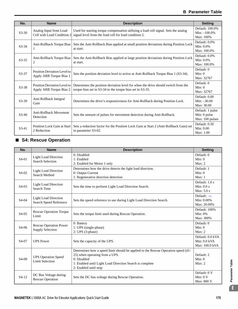
B Parameter Table
MAGNETEK L1000A AC Drive for Elevator Applications Quick Start Guide 175
Par
amet
er T
able
B
■ S4: Rescue Operation
S3-30 Analog Input from Load Cell with Load Condition 2
Used for starting torque compensation utilizing a load cell signal. Sets the analog signal level from the load cell for load condition 2.
Default: 100.0%Min: –100.0%Max: 100%
S3-34 Anti-Rollback Torque Bias 1
Sets the Anti-Rollback Bias applied at small position deviations during Position Lock at start.
Default: 0.0%Min: 0.0%Max: 100.0%
S3-35 Anti-Rollback Torque Bias 2
Sets the Anti-Rollback Bias applied at large position deviations during Position Lock at start.
Default: 0.0%Min: 0.0%Max: 100.0%
S3-37 Position Deviation Level to Apply ARB Torque Bias 1 Sets the position deviation level to active at Anti-Rollback Torque Bias 1 (S3-34).
Default: 0Min: 0Max: 32767
S3-38 Position Deviation Level to Apply ARB Torque Bias 2
Determines the position deviation level for when the drive should switch from the torque bias set in S3-34 to the torque bias set in S3-35.
Default: 0Min: 0Max: 32767
S3-39 Anti-Rollback Integral Gain Determines the drive’s responsiveness for Anti-Rollback during Position Lock.
Default: 0.00Min: –30.00Max: 30.00
S3-40 Anti-Rollback Movement Detection Sets the amount of pulses for movement detection during Anti-Rollback.
Default: 1 pulseMin: 0 pulseMax: 100 pulses
S3-41 Position Lock Gain at Start 2 Reduction
Sets a reduction factor for the Position Lock Gain at Start 2 (Anti-Rollback Gain) set in parameter S3-02.
Default: 0.50Min: 0.00Max: 1.00
No. Name Description Setting
S4-01 Light Load Direction Search Selection
0: Disabled1: Enabled2: Enabled for Motor 1 only
Default: 0Min: 0Max: 2
S4-02 Light Load Direction Search Method
Determines how the drive detects the light load direction.0: Output Current1: Regenerative direction detection
Default: 1Min: 0Max: 1
S4-03 Light Load Direction Search Time Sets the time to perform Light Load Direction Search.
Default: 1.0 sMin: 0.0 sMax: 5.0 s
S4-04 Light Load Direction Search Speed Reference Sets the speed reference to use during Light Load Direction Search.
Default: <5>
Min: 0.00%Max: 20.00%
S4-05 Rescue Operation Torque Limit Sets the torque limit used during Rescue Operation.
Default: 100%Min: 0%Max: 300%
S4-06 Rescue Operation Power Supply Selection
0: Battery1: UPS (single-phase) 2: UPS (3-phase)
Default: 0Min: 0Max: 2
S4-07 UPS Power Sets the capacity of the UPS.Default: 0.0 kVAMin: 0.0 kVAMax: 100.0 kVA
S4-08 UPS Operation Speed Limit Selection
Determines how a speed limit should be applied to the Rescue Operation speed (d1-25) when operating from a UPS.0: Disabled1: Enabled until Light Load Direction Search is complete 2: Enabled until stop
Default: 2Min: 0Max: 2
S4-12 DC Bus Voltage during Rescue Operation Sets the DC bus voltage during Rescue Operation.
Default: 0 VMin: 0 VMax: 800 V
No. Name Description Setting

B Parameter Table
176 MAGNETEK L1000A AC Drive for Elevator Applications Quick Start Guide
■ S5: Short Floor Operation
S4-13Rescue Operation Power Supply Deterioration Detection Level
Determines at which level of backup power supply deterioration a PF5 fault is triggered.
Default: 80%Min: 10%Max: 100%
S4-15<39>
Speed Reference Selection for Rescue Operation Selects the speed reference used for Rescue Operation.
Default: 0Min: 0Max: 1
<5> Default setting is determined by the control mode (A1-02).<39> Available in drive software versions PRG: 7016 and later.
No. Name Description Setting
S5-01
<36> When the length units are set for inches (o1-12 = 1), the setting range becomes 0.00 to 650.00 inches.<37> When the length units are set for inches (o1-12 = 1), the setting range becomes 0.00 to 393.00 inches.
Short Floor Operation Selection
0: Disabled1: Enabled (Short Floor)2: Enabled (Advance Short Floor)
Default: 0Min: 0Max: 2
S5-02 Nominal Speed for Short Floor Calculation
When d1-18 (Speed Priority Selection) is set to 0 or 3, S5-02 determines the rated speed used during Short Floor.
Default: 0.0%Min: 0.0% Max: 100.0%
S5-03 Short Floor Minimum Constant Speed Time
Sets the minimum operation time when the Advanced Short Floor function is enabled (S5-01 = 2).
Default: 0.0 s Min: 0.0 s Max: 2.0 s
S5-04 Distance Calculation Acceleration Time Gain Set for acceleration jerk compensation in Distance Calculation.
Default: 150.0%Min: 50.0%Max: 200.0%
S5-05 Distance Calculation Deceleration Time Gain Set for deceleration jerk compensation in Distance Calculation.
Default: 150.0%Min: 50.0%Max: 200.0%
S5-10 Stopping Method Selection0: Disabled1: Direct Landing2: Leveling Distance Control
Default: 0Min: 0Max: 2
S5-11 Deceleration Distance Sets the deceleration distance when Stop Distance Control is enabled.
Default: 0 mmMin: 0 mmMax: 32767 mm <36>
S5-12 Stop Distance Sets the stopping distance when Stop Distance Control is enabled.
Default: 0 mmMin: 0 mmMax: 10000 mm <37>
S5-13 Direct Landing Minimum Speed Level
Sets the speed level for the start of Direct Landing.Direct Landing is essentially disabled if the starting speed for Direct Landing is less than the maximum output speed multiplied by this parameter (E1-04 × S5-13).
Default: 20%Min: 0%Max: 100%
No. Name Description Setting

B Parameter Table
MAGNETEK L1000A AC Drive for Elevator Applications Quick Start Guide 177
Par
amet
er T
able
B
■ S6: Error Detection
◆ T: Motor Tuning
Enter data into the following parameters to tune the motor and drive for optimal performance.
■ T1: Induction Motor Auto-Tuning
No. Name Description Setting
S6-01
<7> Default setting value is determined by the digital operator display unit selection (o1-03). The default is normally 1.5 m/s2, but when o1-03 = 6, the default becomes 5.0 ft/s2 (Setting Range: 0.0 to 50.0 ft/s2).
Motor Contactor Response Error (SE1) Detection/Reset Selection
0: Detect during stop, SE1 must be manually reset1: Detect during stop, SE1 can be automatically reset2: No SE1 detection
Default: 0Min: 0Max: 2
S6-02Starting Current Error (SE2) Detection Delay Time
Sets a delay time for detecting SE2.
Default: 200 ms Min: 0.00 msMax: [S1-04]-[S1-06]
S6-04 Output Current Error (SE3) Detection Delay Time Sets a delay time for detecting SE3.
Default: 200 ms Min: 0 msMax: 5000 ms
S6-05 Brake Response Error (SE4) Detection Time Sets a delay time for detecting SE4.
Default: 500 ms Min: 0 msMax: 10000 ms
S6-10 Overacceleration Detection Level
If the elevator car accelerates at an abnormal rate, the drive triggers an overspeed fault (dv6) and has the motor coast to stop. Parameter S6-10 determines the acceleration rate that triggers a fault.
Default: <7>
Min: 0.0 m/s2
Max: 20.0 m/s2 <7>
S6-11 Overacceleration Detection Time Sets a primary delay for detecting overacceleration.
Default: 50 ms Min: 0 msMax: 5000 ms
S6-12 Overacceleration Detection Selection
0: Always enabled1: During run only
Default: 0Min: 0Max: 1
S6-15 Speed Reference Loss Detection
Enabled or disables detection for speed reference missing (FrL).0: Disabled1: Enabled
Default: 1Min: 0Max: 1
S6-16 Restart after Baseblock Selection
0: No restart after Baseblock/Safe Torque-Off1: Restart after Baseblock/Safe Torque-Off
Default: 0Min: 0Max: 1
No. Name Description Setting
T1-01 Auto-Tuning Mode Selection
0: Rotational Auto-Tuning 1: Stationary Auto-Tuning 12: Stationary Auto-Tuning for Line-to-Line Resistance4: Stationary Auto-Tuning 2
Default: 0 <5>
Min: 0Max: 4 <18>
T1-02 Motor Rated PowerSets the motor rated power as specified on the motor nameplate.Note: Use the following formula to convert horsepower into kilowatts: kW = HP × 0.746.
Default: <4>
Min: 0.00 kWMax: 650.00 kW
T1-03 Motor Rated Voltage Sets the motor rated voltage as specified on the motor nameplate.
Default: 200.0 V <9>
Min: 0.0 VMax: 255.0 V <9>
T1-04 Motor Rated Current Sets the motor rated current as specified on the motor nameplate.
Default: <4>
Min: 10% of drive rated currentMax: 200% of drive rated current <10>

B Parameter Table
178 MAGNETEK L1000A AC Drive for Elevator Applications Quick Start Guide
■ T2: PM Motor Auto-Tuning
T1-05 Motor Base Frequency Sets the rated frequency of the motor as specified on the motor nameplate.Default: 50.0 HzMin: 0.0 HzMax: 120.0 Hz
T1-06 Number of Motor Poles Sets the number of motor poles as specified on the motor nameplate.Default: 4Min: 2Max: 48
T1-07 Motor Base Speed Sets the rated speed of the motor as specified on the motor nameplate.
Default: 1450 r/minMin: 0 r/minMax: 24000 r/min
T1-08 Encoder Resolution(pulses per revolution)
Set the number of pulses per revolution for the PG being used (pulse generator or encoder).
Default: 1024 pprMin: 0 pprMax: 60000 ppr
T1-09Motor No-Load Current (Stationary Auto-Tuning 1 and 2)
Sets the no-load current for the motor.After setting the motor capacity to T1-02 and the motor rated current to T1-04, this parameter will automatically display the no-load current for a standard 4 pole Magnetek motor. Enter the no-load current as indicated on the motor test report.
Default: –Min: 0 AMax: Up to T1-04 <10>
T1-10 Motor Rated Slip (Stationary Auto-Tuning 2)
Sets the motor rated slip.After setting the motor capacity to T1-02, this parameter will automatically display the motor slip for a standard 4 pole Magnetek motor. Enter the motor slip as indicated on the motor test report.
Default: –Min: 0.00 HzMax: 20.00 Hz
<4> Default setting value varies by the drive model (o2-04).<5> Default setting is determined by the control mode (A1-02).<9> Values shown here are for 200 V class drives. Double the value when using a 400 V class drive.<10> The display resolution depends on the rated output power of the drive. Models CIMR-LU2A0008 to 2A0033 and CIMR-LU4A0005 to
4A0018 display values in 0.01 A units, while models CIMR-LU2A0047 to 2A0415 and CIMR-LU4A0024 to 4A0260 display values in 0.1 A units.
<18> The variety of Auto-Tuning methods depends on the control mode setting. V/f Control allows T1-01 to be set to 2 or 3, while vector control modes (OLV and CLV) allow T1-01 to be set to 0 through 4.
No. Name Description Setting
T2-01 Motor Auto-Tuning Mode Selection
0: Motor Data input1: Stationary Auto-Tuning2: Stationary stator resistance Auto-Tuning3: Initial magnet pole search parameters Auto-Tuning4: Encoder offset stationary Auto-Tuning10: Encoder offset rotational Auto-Tuning11: Rotational back EMF constant Auto-Tuning
Default: 0Min: 0Max: 11
T2-04 Motor Rated Power Sets the motor rated power as indicated on the motor nameplate.Default: <4>
Min: 0.00 kWMax: 650.00 kW
T2-05 Motor Rated Voltage Enter the motor rated voltage as indicated on the motor nameplate.
Default: 200.0 V <9>
Min: 0.0 VMax: 255.0 V <9>
T2-06 Motor Rated Current Enter the motor rated current as indicated on the motor nameplate.
Default: <4>
Min: 10% of drive rated currentMax: 200% of drive rated current <10>
T2-08 Number of Motor Poles Enter the number of motor poles for the motor as indicated on the motor nameplate.Default: 6Min: 2Max: 48
T2-09 Motor Base Speed Enter the base speed for the motor as indicated on the motor nameplate.Default: 150 r/minMin: 0 r/minMax: 24000 r/min
No. Name Description Setting

B Parameter Table
MAGNETEK L1000A AC Drive for Elevator Applications Quick Start Guide 179
Par
amet
er T
able
B
◆ U: Monitors
Monitor parameters allow the user to view drive status, fault information, and other data concerning drive operation.
■ U1: Operation Status Monitors
T2-10 Single Phase Stator Resistance Enter the 1-phase resistance of the stator winding.
Default: –Min: 0.000 ΩMax: 65.000 Ω
T2-11 Motor d-Axis Inductance Enter the d-axis inductance for the motor as indicated on the motor nameplate.Default: –Min: 0.00 mHMax: 600.00 mH
T2-12 Motor q-Axis Inductance Enter the q-axis inductance for the motor as indicated on the motor nameplate.Default: –Min: 0.00 mHMax: 600.00 mH
T2-13 Induced Voltage Constant Unit Selection
0: mV/(r/min). E5-09 will automatically be set to 0.0, and E5-24 will be used.1: mV/(rad/sec). E5-24 will automatically be set to 0.0, and E5-09 will be used.
Default: 1Min: 0Max: 1
T2-14 Motor Induced Voltage Constant
Enter the induced voltage coefficient for the motor as indicated on the motor nameplate.
Default: –Min: 0.0Max: 6500.0 <30>
T2-16 Encoder Resolution Sets the number of pulses per revolution for the PG being used (pulse generator or encoder).
Default: 1024 pprMin: 1 pprMax: 15000 ppr
T2-17 Encoder Offset Sets the offset between encoder offset and the rotor magnetic axis.Default: 0.0 degMin: -180.0 degMax: 180.0 deg
<4> Default setting value varies by the drive model (o2-04).<9> Values shown here are for 200 V class drives. Double the value when using a 400 V class drive.<10> The display resolution depends on the rated output power of the drive. Models CIMR-LU2A0008 to 2A0033 and CIMR-LU4A0005 to
4A0018 display values in 0.01 A units, while models CIMR-LU2A0047 to 2A0415 and CIMR-LU4A0024 to 4A0260 display values in 0.1 A units.
<30> Setting units are determined by the induced voltage constant unit selection for PM motors set to T2-13.
No. Name Description Analog Output Level Unit
U1-01 Speed Reference Monitors the speed reference.10 V: Max frequency(-10 to +10 V)
0.01%<31>
U1-02 Output Speed Displays the output speed. 10 V: Max frequency(-10 to +10 V)
0.01%<31>
U1-03 Output Current Displays the output current. 10 V: Drive rated current <10> <40>
U1-04 Control Method
0: V/f Control2: Open Loop Vector Control3: Closed Loop Vector Control7: Closed Loop Vector Control for PM
No signal output available –
U1-05 Speed Feedback Displays the motor speed feedback. 10 V: Max Frequency(-10 to +10 V)
0.01%<31>
U1-06 Output Voltage Reference Displays the output voltage. 10 V:
200 Vrms <9>0.1 Vac
U1-07 DC Bus Voltage Displays the DC bus voltage. 10 V: 400 V <9> 1 Vdc
U1-08 Output Power Displays the output power (this value is calculated internally).
10 V: Drive rated power (kW) (-10 to +10 V)
<12>
No. Name Description Setting

B Parameter Table
180 MAGNETEK L1000A AC Drive for Elevator Applications Quick Start Guide
U1-09 Torque Reference Monitors the internal torque reference.10 V: Motor rated torque(-10 to +10 V)
0.1%
U1-10 Input Terminal Status
Displays the input terminal status.
No signal output available –
U1-11 Output Terminal Status
Displays the output terminal status.
No signal output available –
U1-12 Drive Status
Displays the drive operation status.
No signal output available –
U1-13 Terminal A1 Input Voltage Displays the voltage input to terminal A1. 10 V: 100%
(-10 to +10 V) 0.1%
U1-14 Terminal A2 Input Voltage Displays the voltage input to terminal A2. 10 V: 100%
(-10 to +10 V) 0.1%
U1-16 Output Speed after Soft Start
Displays output speed with ramp time and jerk settings. Units determined by o1-03.
10 V: Max frequency(-10 to +10 V)
0.01%<31>
No. Name Description Analog Output Level Unit
U1 - 10=00000000Digital input 1 (terminal S1 enabled)Digital input 2 (terminal S2 enabled)Digital input 3 (terminal S3 enabled)Digital input 4 (terminal S4 enabled)Digital input 5 (terminal S5 enabled)Digital input 6 (terminal S6 enabled)Digital input 7 (terminal S7 enabled)Digital input 8 (terminal S8 enabled)
11111111
U1 - 11=00000000Multi-Function Digital Output (terminal M1-M2)
Digital Output (terminal M3-M4)
Digital Output (terminal M5-M6)
Multi-Function
Multi-Function
Digital Output (terminal P1-C1)
Multi-Function
Digital Output (terminal P2-C2)
Multi-Function
Not UsedFault Relay(terminal MA-MC closed
MA-MC open)
1
1
1
1
1
1
U1 - 12=00000000During runDuring zero-speedDuring down directionDuring fault reset signal inputDuring speed agreeDrive readyDuring alarm detectionDuring fault detection
11111111

B Parameter Table
MAGNETEK L1000A AC Drive for Elevator Applications Quick Start Guide 181
Par
amet
er T
able
B
U1-17 DI-A3 Option Card Input Status
Displays the reference value input from the DI-A3 option card.Display will appear in hexadecimal as determined by the digital card input selection in F3-01.3FFFF: Set (1 bit) + sign (1 bit) + 16 bit
No signal output available –
U1-18 oPE Fault Parameter Displays the parameter number that caused the oPE02 or oPE08 (Operation error). No signal output available –
U1-19 MEMOBUS/Modbus Error Code
Displays the contents of a MEMOBUS/Modbus error.
No signal output available –
U1-25 Software Number (Flash) FLASH ID No signal output
available –
U1-26 Software No. (ROM) ROM ID No signal output available –
<9> Values shown here are for 200 V class drives. Double the value when using a 400 V class drive.<10> The display resolution depends on the rated output power of the drive. Models CIMR-LU2A0008 to 2A0033 and CIMR-LU4A0005 to
4A0018 display values in 0.01 A units, while models CIMR-LU2A0047 to 2A0415 and CIMR-LU4A0024 to 4A0260 display values in 0.1 A units.
<12> The display resolution depends on the rated output power of the drive. Models CIMR-LU2A0008 to 2A0033 and CIMR-LU4A0005 to 4A0018 display values in 0.01 kW units, while models CIMR-LU2A0047 to 2A0415 and CIMR-LU4A0024 to 4A0260 display values in 0.1 kW units.
<31> Setting units are determined by the digital operator display unit selection (o1-03). When o1-03 = 0, the value is set in Hertz. When o1-03 = 4 or 5, the value is displayed in m/s. When o1-03 = 6, the value is displayed in ft/min.
<40> When checking the values of U1-03, U2-05 and U4-13 with the digital operator they are displayed in units of amperes, but when they are checked using MEMOBUS communications, the monitor value in MEMOBUS communications is: displayed numeric value / 8192 × drive’s rated current (A), from the condition “8192 (maximum value) = drive’s rated current (A)”.
No. Name Description Analog Output Level Unit
U1 - 19=00000000CRC ErrorData Length ErrorNot Used
Parity ErrorOverrun ErrorFraming Error
Timed Out
Not Used
11011110

B Parameter Table
182 MAGNETEK L1000A AC Drive for Elevator Applications Quick Start Guide
■ U2: Fault Trace
No. Name Description Analog Output Level Unit
U2-01
<10> The display resolution depends on the rated output power of the drive. Models CIMR-LU2A0008 to 2A0033 and CIMR-LU4A0005 to 4A0018 display values in 0.01 A units, while models CIMR-LU2A0047 to 2A0415 and CIMR-LU4A0024 to 4A0260 display values in 0.1 A units.
<31> Setting units are determined by the digital operator display unit selection (o1-03). When o1-03 = 0, the value is set in Hertz. When o1-03 = 4 or 5, the value is displayed in m/s. When o1-03 = 6, the value is displayed in ft/min.
<40> When checking the values of U1-03, U2-05 and U4-13 with the digital operator they are displayed in units of amperes, but when they are checked using MEMOBUS communications, the monitor value in MEMOBUS communications is: displayed numeric value / 8192 × drive’s rated current (A), from the condition “8192 (maximum value) = drive’s rated current (A)”.
Current Fault Displays the current fault. No signal output available –
U2-02 Previous Fault Displays the previous fault. No signal output available –
U2-03 Speed Reference at Previous Fault Displays the speed reference at the previous fault. No signal output
available0.01%
<31>
U2-04 Output Speed at Previous Fault Displays the output speed at the previous fault. No signal output
available0.01%
<31>
U2-05 Output Current at Previous Fault Displays the output current at the previous fault. No signal output
available <10> <40>
U2-06 Motor Speed at Previous Fault Displays the motor speed at the previous fault. No signal output
available0.01%
<31>
U2-07 Output Voltage at Previous Fault Displays the output voltage at the previous fault. No signal output
available 0.1 Vac
U2-08 DC Bus Voltage at Previous Fault Displays the DC bus voltage at the previous fault. No signal output
available 1 Vdc
U2-09 Output Power at Previous Fault Displays the output power at the previous fault. No signal output
available 0.1 kW
U2-10 Torque Reference at Previous Fault Displays the torque reference at the previous fault. No signal output
available 0.1%
U2-11 Input Terminal Status at Previous Fault Displays the input terminal status at the previous fault. Displayed as in U1-10. No signal output
available –
U2-12 Output Terminal Status at Previous Fault Displays the output status at the previous fault. Displayed as in U1-11. No signal output
available –
U2-13 Drive Operation Status at Previous Fault
Displays the operation status of the drive at the previous fault. Displayed as in U1-12.
No signal output available –
U2-14 Cumulative Operation Time at Previous Fault Displays the cumulative operation time at the previous fault. No signal output
available 1 h
U2-15 Soft Starter Output at Previous Fault
Displays the run speed after a soft start when a previous fault occurred. Displayed as in U1-16.
No signal output available
0.01%<31>
U2-16 Motor q-Axis Current at Previous Fault
Displays the q-axis current for the motor at the previous fault. Displayed as in U6-01.
No signal output available 0.1%
U2-17 Motor d-Axis Current at Previous Fault
Displays the d-axis current for the motor at the previous fault. Displayed as in U6-02.
No signal output available 0.1%
U2-20 Heatsink Temperature at Previous Fault
Displays the temperature of the heatsink when the most recent fault occurred. Displayed as in U4-08.
No signal output available 1°C
U2-21 Peak Hold Current during Fault Displays the peak current that occurred just prior to the previous fault. No signal output
available 0.01 A
U2-22 Peak Hold Frequency during Fault
Displays the output frequency when the peak current displayed in U2-21 occurred.
No signal output available 0.01 Hz

B Parameter Table
MAGNETEK L1000A AC Drive for Elevator Applications Quick Start Guide 183
Par
amet
er T
able
B
■ U3: Fault History
■ U4: Maintenance Monitors
No. Name Description Analog Output Level Unit
U3-01 to U3-04
First to 4th Most Recent Fault Displays the first to the fourth most recent faults. No signal output
available –
U3-05 to U3-10
5th to 10th Most Recent Fault
Displays the fifth to the tenth most recent faults.After ten faults have occurred in the drive, data for the oldest fault is deleted. The most recent fault appears in U3-01, with the next most recent fault appearing in U3-02. The data is moved to the next monitor parameter every time a fault occurs.
No signal output available –
U3-11 to U3-14
Cumulative Operation Time at 1st to 4th Most Recent Fault
Displays the cumulative operation time when the first to the fourth most recent faults occurred.
No signal output available 1 h
U3-15 to U3-20
Cumulative Operation Time at 5th to 10th Most Recent Fault
Displays the cumulative operation time when the fifth to the tenth most recent faults occurred.
No signal output available 1 h
No. Name Description Analog Output Level Unit
U4-01<41>
Cumulative Operation Time
Displays the cumulative operation time of the drive. The value for the cumulative operation time counter can be reset in parameter o4-01. Use parameter o4-02 to determine if the operation time should start as soon as the power is switched on or only while the Up/Down command is present. The maximum number displayed is 99999, after which the value is reset to 0.
No signal output available 1 h
U4-03<42>
Cooling Fan Operation Time
Displays the cumulative operation time of the cooling fan. The default value for the fan operation time is reset in parameter o4-03. This value will reset to 0 and start counting again after reaching 99999.
No signal output available 1 h
U4-04 Cooling Fan Maintenance
Displays main cooling fan usage time in as a percentage of its expected performance life. Parameter o4-03 can be used to reset this monitor. The fan should be replaced when this monitor reaches 90%.
No signal output available 1%
U4-05 Capacitor MaintenanceDisplays main circuit capacitor usage time in as a percentage of their expected performance life. The capacitors should be replaced when this monitor reaches 90%. Parameter o4-05 can be used to reset this monitor.
No signal output available 1%
U4-06 Soft Charge Bypass Relay Maintenance
Displays the soft charge bypass relay maintenance time as a percentage of its estimated performance life. The soft charge relay should be replaced when this monitor reaches 90%. Parameter o4-07 can be used to reset this monitor.
No signal output available 1%
U4-07 IGBT MaintenanceDisplays IGBT usage time as a percentage of the expected performance life. The IGBTs should be replaced when this monitor reaches 90%. Parameter o4-09 can be used to reset this monitor.
No signal output available 1%
U4-08 Heatsink Temperature Displays the heatsink temperature. 10 V: 100°C 1°C
U4-09 LED Check Lights all segments of the LED to verify that the display is working properly. No signal output available –
U4-10 kWh, Lower 4 DigitsMonitors the drive output power. The value is shown as a 9 digit number displayed across two monitor parameters, U4-10 and U4-11.Example:12345678.9 kWh is displayed as:U4-10: 678.9 kWhU4-11: 12345 MWh
No signal output available 1 kWh
U4-11 kWh, Upper 5 Digits No signal output available 1 MWh
U4-13 Peak Hold Current Displays the highest current value that occurred during a ride. No signal output available
0.01 A<40>
U4-14 Peak Hold Output Frequency Displays the output frequency when the current value shown in U4-13 occurred. No signal output
available 0.01 Hz
U4-16 Motor Overload Estimate (oL1)
Shows the value of the motor overload detection accumulator. 100% is equal to the oL1 detection level. 10 V: 100% 0.1%

B Parameter Table
184 MAGNETEK L1000A AC Drive for Elevator Applications Quick Start Guide
U4-17 Drive Overload Calculations (OL2)
Displays the level of the drive overload detection (oL2). A value of 100% is equal to the oL2 detection level. 10 V = 100% 0.1%
U4-18 Speed Reference Selection Results
Displays the source for the speed reference as XY-nn.X: indicates which reference is used:1 = Reference 1 (b1-01)Y-nn: indicates the reference source0-01 = Digital operator1-01 = Analog (terminal A1)1-02 = Analog (terminal A2)2-02 to 8 = Digital Inputs (d1-02 to 8)3-01 = MEMOBUS/Modbus communications4-01 = Communication option card
No signal output available –
U4-19Speed Reference from MEMOBUS/Modbus Comm.
Displays the speed reference provided by MEMOBUS/Modbus (decimal). No signal output available
0.01%<31>
U4-20 Speed Reference From Option Card Displays the speed reference input by an option card (decimal). No signal output
available0.01%
<31>
U4-21 Up/Down Command Source Selection
Displays the source for the Up/Down command as XY-nn.X: Indicates which Up/Down command source is used:1 = Reference 1 (b1-02)Y: Input power supply data0 = Digital operator1 = External terminals3 = MEMOBUS/Modbus communications4 = Communication option cardnn: Up/Down command limit status data00: No limit status.01: Up/Down command was left on when stopped in the PRG mode02: Up/Down command was left on when switching from LOCAL to REMOTE operation03: Waiting for soft charge bypass contactor after power up (Uv or Uv1 flashes after 10 s)04: Waiting for "Up/Down Command Prohibited" time period to end05: Fast Stop (multi-function input, operator)07: During baseblock while coast to stop with timer08: Speed reference is below minimal reference during baseblock09: Waiting for Enter command
No signal output available –
U4-22MEMOBUS/Modbus Communications Reference
Displays the drive control data set by MEMOBUS/Modbus communications register no. 0001H as a four-digit hexadecimal number.
No signal output available –
U4-23 Communication Option Card Reference
Displays drive control data set by an option card as a four-digit hexadecimal number.
No signal output available –
U4-24 Number of Travels(Lower 4 digit) Displays the lower four digits for the number of trips the drive has made.
No signal output available 1 time
U4-25 Number of Travels(Higher 4 digit) Displays the upper four digits for the number of trips the drive has made. No signal output
available 1 time
U4-26 Max. Current during Acceleration Shows the maximum current that occurred during acceleration. No signal output
available 0.1 A
U4-27 Max. Current during Deceleration Shows the maximum current that occurred during deceleration. No signal output
available 0.1 A
U4-28 Max. Current during Constant Speed Shows the maximum current that occurred during ride at top speed. No signal output
available 0.1 A
U4-29 Max. Current during Leveling Speed
Shows the maximum current that occurred during ride at leveling speed. No signal output available 0.1 A
U4-30 Slip Compensation Value
Shows the slip compensation value. No signal output available 0.01%
No. Name Description Analog Output Level Unit

B Parameter Table
MAGNETEK L1000A AC Drive for Elevator Applications Quick Start Guide 185
Par
amet
er T
able
B
Note: Fault trace (i.e., the fault history) is not maintained when CPF00, CPF01, CPF06, CPF24, oFA00, oFb00, oFC00, Uv1, Uv2, or Uv3 occur.
U4-31 Car Acceleration Rate Shows the car acceleration rate. No signal output available
0.01 m/s2
U4-40 Speed Reference Limit at Rescue Operation
Displays the speed limit for Rescue Operation based on how much power the backup battery or UPS has. Displays 0% when Rescue Operation is not being performed.
No signal output available 1%
U4-42<35>
Remaining Distance Displays the remaining distance according to the stopping method selected.10 V: S5-10 = 1: S5-11S5-10 = 2: S5-12
1 mm
U4-43<35>
Minimum Deceleration Distance Displays the Minimum Deceleration Distance calculated by E1-04. No signal output
available 1 mm
U4-44<35>
Minimum Stop Distance Displays the Minimum Stop Distance calculated by d1-26. No signal output
available 1 mm
<31> Setting units are determined by the digital operator display unit selection (o1-03). When o1-03 = 0, the value is set in Hertz. When o1-03 = 4 or 5, the value is displayed in m/s. When o1-03 = 6, the value is displayed in ft/min.
<35> o1-12 (Length Units) determines the units. When o1-12 is set to 0, the unit is millimeters. When o1-12 is set to 1, the unit is inch.<40> When checking the values of U1-03, U2-05 and U4-13 with the digital operator they are displayed in units of amperes, but when they are
checked using MEMOBUS communications, the monitor value in MEMOBUS communications is: displayed numeric value / 8192 × drive’s rated current (A), from the condition “8192 (maximum value) = drive’s rated current (A)”.
<41> The MEMOBUS communications data is in 10 h units. If data in 1 h units are also required, refer to register number 0099H.<42> The MEMOBUS communications data is in 10 h units. If data in 1 h units are also required, refer to register number 009BH.
No. Name Description Analog Output Level Unit

B Parameter Table
186 MAGNETEK L1000A AC Drive for Elevator Applications Quick Start Guide
■ U6: Control Monitors
No. Name Description Analog Output Level Unit
U6-01
<9> Values shown here are for 200 V class drives. Double the value when using a 400 V class drive.
Motor Secondary Current (Iq)
Displays the value of the motor secondary current (Iq). Motor rated secondary current is 100%.
10 V: Motor secondary rated current(-10 to +10 V)
0.1%
U6-02 Motor Excitation Current (Id)
Displays the value calculated for the motor excitation current (Id). Motor rated secondary current is 100%.
10 V: Motor secondary rated current(-10 to +10 V)
0.1%
U6-03 Speed Control Loop Input
Displays the input and output values of the speed control loop.
10 V: Max frequency(-10 to +10 V)
0.01%
U6-04 Speed Control Loop Output
10 V: Motor secondary rated current(-10 to +10 V)
U6-05 Output Voltage Reference (Vq) Output voltage reference (Vq) for the q-axis.
10 V: 200 Vrms <9>
(-10 to +10 V)0.1 Vac
U6-06 Output Voltage Reference (Vd) Output voltage reference (Vd) for the d-axis.
10 V: 200 Vrms <9>
(-10 to +10 V)0.1 Vac
U6-07 q-Axis Current Controller Output
Displays the output value for current control relative to motor secondary current (q-axis).
10 V: 200 Vrms <9>
(-10 to +10 V)0.1%
U6-08 d-Axis Current Controller Output
Displays the output value for current control relative to motor secondary current (d-axis).
10 V: 200 Vrms <9>
(-10 to +10 V)0.1%
U6-13 Flux Position Detection (sensor)
Monitors the value of the flux position detection (sensor). 10 V: 180 deg-10 V: -180 deg 0.1 deg
U6-18 Speed Detection PG1 Counter
Monitors the number of pulses for speed detection (PG1). 10 V: 65536 1 pulse
U6-22 Position Lock Deviation Counter
Displays how far the rotor has moved from its last position in PG pulses (multiplied by 4).
10 V: No. of pulses per revolution(-10 to +10 V)
1 pulse
U6-25 Feedback Control Output Output monitor for the speed control loop.
10 V: Motor secondary rated current(-10 to +10 V)
0.01%
U6-26 Inertia Compensation Output Output monitor for Inertia Compensation.
10 V: Motor secondary rated current(-10 to +10 V)
0.01%
U6-56 Speed Feedback Compensation Output Displays observed speed when n5-07=1 or 2. 10 V: Max
output frequency 0.01%
U6-80 to U6-99 Option Monitor 1 to 20 Monitors reserved to display data from option cards. No signal output
available –

B Parameter Table
MAGNETEK L1000A AC Drive for Elevator Applications Quick Start Guide 187
Par
amet
er T
able
B
◆ Defaults and Setting Ranges by Display Unit Selection (o1-03)
Table 52 shows parameters, default settings, and setting ranges that change according to parameter o1-03, Display Unit Selection.
Table 52 Defaults and Setting Ranges by Display Unit Selection (o1-03)
No.
<1> Automatically calculated according to the values set to o1-20, o1-21, o1-22, and E2- /E5- parameters.<2> Automatically calculated according to the values set to the E2- /E5- parameters.
Name
o1-03 (Digital Operator Display Unit Selection)
Default 0(0.01 Hz)
1(0.01%)
2(r/min)
3(User-set)
4(Elevator units 1)
5(Elevator units 2)
6(Elevator units 3)
C1-01 Acceleration Ramp 1
0.00 to 600.00 s 0.00 to <1> m/s2
0.00 to <1> ft/s2
1.50 s
C1-02 Deceleration Ramp 1C1-03 Acceleration Ramp 2C1-04 Deceleration Ramp 2C1-05 Acceleration Ramp 3C1-06 Deceleration Ramp 3C1-07 Acceleration Ramp 4C1-08 Deceleration Ramp 4C1-09 Fast Stop TimeC1-15 Inspection Run Deceleration Ramp 0.00 sC2-01 Jerk at Accel Start
0.00 to 10.00 s 0.00 to <1> m/s3
0.00 to <1> ft/s3 0.50 s
C2-02 Jerk at Accel EndC2-03 Jerk at Decel StartC2-04 Jerk at Decel EndC2-05 Jerk below leveling speedC1-11 Accel/Decel Switching Speed
0.00 to[E1-04] Hz
0.00 to 100.00%
0.00 to <2>
r/min User define 0.00 to <1> m/s 0.00 to <1> ft/min
0.0%d1-01 Speed Reference 1
0.00%
d1-02 Speed Reference 2d1-03 Speed Reference 3d1-04 Speed Reference 4d1-05 Speed Reference 5d1-06 Speed Reference 6d1-07 Speed Reference 7d1-08 Speed Reference 8d1-19 Nominal Speed 100.0%d1-20 Intermediate Speed 1
0.00%d1-21 Intermediate Speed 2d1-22 Intermediate Speed 3d1-23 Releveling Speedd1-24 Inspection Operation Speed 50.00%d1-25 Rescue Operation Speed 10.00%d1-26 Leveling Speed 8.00%

188 MAGNETEK L1000A AC Drive for Elevator Applications Quick Start Guide
C Standards Compliance
C Standards Compliance
◆ European StandardsFigure 79
Figure 86 CE Mark
The CE mark indicates compliance with European safety and environmental regulations. It is required for engaging in business and commerce in Europe.
European standards include the Machinery Directive for machine manufacturers, the Low Voltage Directive for electronics manufacturers, and the EMC guidelines for controlling noise.
This drive displays the CE mark based on the EMC guidelines and the Low Voltage Directive.
• Low Voltage Directive: 2006/95/EC• EMC Guidelines: 2004/108/EC
Devices used in combination with this drive must also be CE certified and display the CE mark. When using drives displaying the CE mark in combination with other devices, it is ultimately the responsibility of the user to ensure compliance with CE standards. After setting up the device, verify that conditions meet European standards.
■ CE Low Voltage Directive Compliance
This drive has been tested according to European standard IEC61800-5-1, and it fully complies with the Low Voltage Directive.
To comply with the Low Voltage Directive, be sure to meet the following conditions when combining this drive with other devices:
Area of Use
Do not use drives in areas with pollution higher than severity 2 and overvoltage category 3 in accordance with IEC664.

C Standards Compliance
MAGNETEK L1000A AC Drive for Elevator Applications Quick Start Guide 189
Sta
ndar
ds
Cli
C
Factory Recommended Branch Circuit ProtectionTable 53 Recommended Input Fuse Selection
Grounding
The drive is designed to be used in T-N (grounded neutral point) networks. If installing the drive in other types of grounded systems, contact your Magnetek representative for instructions.
Drive ModelCIMR-LU
L1000
Nominal Output Power
HPAC Drive Input
AmpsMCCB Rating
Amps<1>
<1> Maximum MCCB Rating is 15 A, or 200% of drive input current rating, whichever is larger. MCCB voltage rating must be 600 VAC or greater.
Time Delay Fuse Rating
Amps <2>
<2> Maximum Time Delay fuse is 175% of drive input current rating. This covers any Class CC, J or T class fuse.
Non-time Delay Fuse
Rating Amps<3>
<3> Maximum Non-time Delay fuse is 300% of drive input current rating. This covers any CC, J or T class fuse.
Bussmann Semi-conductor Fuse
Rating(Fuse Ampere) <4>
<4> When using semiconductor fuses, Bussmann FWH and FWP are required for UL compliance. Select FWH for 240 V and 480 V models and FWP fuses for 600 V models.
<5> Class L fuse is also approved for this rating.
240 V Models2A0008 2 7.5 15 12 20 FWH-70B (70)2A0011 3 11 20 17.5 30 FWH-70B (70)2A0014 3 15.6 25 25 40 FWH-90B (90)2A0018 5 18.9 35 30 50 FWH-90B (90)2A0025 7.5 28 50 40 75 FWH-100B (100)2A0033 10 37 60 60 100 FWH-200B (200)2A0047 15 52 100 90 150 FWH-200B (200)2A0060 20 68 125 110 200 FWH-200B (200)2A0075 25 80 150 125 225 FWH-300A (300)2A0085 30 82 150 125 225 FWH-300A (300)2A0115 40 111 200 175 250 FWH-350A (350)2A0145 50 136 250 225 350 FWH-400A (400)2A0180 60 164 300 250 450 FWH-400A (400)2A0215 75 200 400 350 600 FWH-600A (600)2A0283 100 271 500 450 800 FWH-700A (700)2A0346 125 324 600 500 900 <5> FWH-800A (800)2A0415 150 394 700 600 1100 <5> FWH-1000A (1000)
480 V Models4A0005 3 4.4 15 7 12 FWH-70B (70)4A0006 3 6 15 10 17.5 FWH-70B (70)4A0007 5 8.2 15 12 20 FWH-90B (90)4A0009 5 10.4 20 17.5 30 FWH-90B (90)4A0015 7.5 15 30 25 40 FWH-80B (80)4A0018 10 20 40 35 60 FWH-100B (100)4A0024 15 29 50 50 80 FWH-125B (125)4A0031 20 39 75 60 110 FWH-200B (200)4A0039 25 47 75 75 125 FWH-250A (250)4A0045 30 43 75 75 125 FWH-250A (250)4A0060 40 58 100 100 150 FWH-250A (250)4A0075 60 71 125 110 200 FWH-250A (250)4A0091 60 86 150 150 250 FWH-250A (250)4A0112 75 105 175 175 300 FWH-350A (350)4A0150 100 142 225 225 400 FWH-400A (400)4A0180 125 170 250 250 500 FWH-500A (500)4A0216 150 207 350 350 600 FWH-600A (600)4A0260 200 248 400 400 700 FWH-700A (700)

C Standards Compliance
190 MAGNETEK L1000A AC Drive for Elevator Applications Quick Start Guide
CE Standards Compliance for DC Power Supply Input
To meet CE standards, the following fuses should be installed. For details, refer to Figure 87.Figure 80
Figure 87 Example of DC Power Supply Input (two L1000A drives connected in series)
Note: 1. When connecting multiple drives together, make sure that each drive has its own fuse. If any one fuse blows, all fuses should be replaced.
2. For an AC power supply, refer to Standard Connection Diagram on page 21.3. The recommended fuses and fuse holders are made by Fuji Electric.
Table 54 Fuses and Fuse Holders
Drive ModelCIMR-LU
<1> DC is not available for UL standards.<2> Manufacturer does not recommend a specific fuse holder for this fuse. Contact Magnetek or your nearest sales representative on fuse
dimensions.
DC Power Supply Input <1>
Drive ModelCIMR-LU
DC Power Supply Input <1>
Fuse Fuse Holder Fuse Fuse Holder
Type
Rated Short-circuit
Breaking Current
(kA)
Qty. Type Qty. Type
Rated Short-circuit
Breaking Current
(kA)
Qty. Type Qty.
200 V Class 400 V Class2A0008
CR2LS-50
100
2 CM-1A 1
4A0005
CR6L-50
100
2 CMS-4 22A0011 4A00062A0014 CR2LS-75 4A00072A0018 CR2LS-100 4A00092A0025 CR2L-125
2 CM-2A 1 4A0015
CR6L-75
2 CMS-5 22A0033 CR2L-150 4A00182A0047 CR2L-175 4A0024 CR6L-1002A0060 CR2L-225
2 <2>
4A0031CR6L-150
2A0075 CR2L-260 4A00392A0085 CR2L-300 4A0045 CR6L-200
2 <2>
2A0115 CR2L-350 4A0060CR6L-250
2A0145 CR2L-400 4A00752A0180 CR2L-450 4A0091 CR6L-3002A0215
CR2L-600 4A0112 CR6L-350
2A0283 4A0150 CR6L-4002A0346 CS5F-800
200 4A0180
CS5F-600 2002A0415 CS5F-1200 4A0216 4A0260
M
M
W/T3
Drive
V/T2U/T1
+1_
W/T3
Drive
V/T2U/T1
+1_
+_
Fuse
Fuse
DC power supply(converter)

C Standards Compliance
MAGNETEK L1000A AC Drive for Elevator Applications Quick Start Guide 191
Sta
ndar
ds
Cli
C
Guarding Against Harmful Materials
When installing IP00 enclosure drives, use an enclosure that prevents foreign material from entering the drive from above or below.
■ EMC Guidelines Compliance
This drive is tested according to European standards EN61800-3: 2004, and complies with the European standards EN12015 (requires an optional AC reactor) and EN12016.
Note: Make sure the protective earthing conductor complies with technical standards and local safety regulations. Because the leakage current exceeds 3.5 mA when an EMC filter is installed, IEC 61800-5-1 states that either the power supply must be automatically disconnected in case of discontinuity of the protective earthing conductor or a protective earthing conductor with a cross-section of at least 10 mm2 (Cu) or 16 mm2 (Al) must be used.
EMC Filter Installation
The following conditions must be met to ensure continued compliance with European standards EN12015 and EN12016. Refer to EMC Filters on page 193 for EMC filter selection.
Installation Method
Verify the following installation conditions to ensure that other devices and machinery used in combination with this drive also comply with EMC guidelines.
1. Install an EMC noise filter to the input side specified by Magnetek for compliance with European standards.2. Place the drive and EMC noise filter in the same enclosure.3. Use braided shield cable for the drive and motor wiring, or run the wiring through a metal conduit.4. Keep wiring as short as possible. Ground the shield on both the drive side and the motor side.
Figure 81
Figure 88 Installation Method
A – Drive D – Metal conduitB – 10 m max cable length between drive and motor E – Ground wire should be as short as possible.C – Motor
A
B
D
E
C
M
U/T1
V/T2
W/T3
U
V
W

C Standards Compliance
192 MAGNETEK L1000A AC Drive for Elevator Applications Quick Start Guide
5. Make sure the ground conductor complies with technical standards and local safety rules. When an EMC filter is installed, the leakage current exceeds 3.5 mA. Therefore according to IEC61800-5-1, at least one of the conditions below must be satisfied: a) The cross-section of the protective earthing conductor must be at least 10 mm2 (Cu) or 16 mm2 (Al). b) The power supply must be disconnected automatically in case of discontinuity of the protective earthing
conductor.Figure 82
Figure 89 Ground Area
6. Connect an AC reactor or a DC link choke to minimize harmonic distortion.
Three-Phase 200 V / 400 V ClassFigure 83
Figure 90 EMC Filter and Drive Installation for CE Compliance (Three-Phase 200 V / 400 V Class)
A – Braided shield cable C – Cable clamp (conductive)B – Metal panel
C B
A
L3L3 L2L2 L1L1L3 L2 L1
E
L3
L2
L1PE
Make sure the ground wire is grounded
Enclosure panel
Metal plateGrounding surface
(remove any paint or sealant)
Drive
Grounding surface (remove any paint or sealant)
Motor cable (braided shield cable, max. 10 m)Cable clamp
Ground plate (scrape off any visible paint)
EMC noise filter
MotorGround the cable shield

C Standards Compliance
MAGNETEK L1000A AC Drive for Elevator Applications Quick Start Guide 193
Sta
ndar
ds
Cli
C
EMC Filters
Install the drive with the EMC filters to comply with the EN61800-3/EN12015 requirements.Note: If the Safe Disable function of the drive is part of the safety concept of a machine or installation and used for a safe stop according
to EN60204-1, stop category 0, use these filters recommended by Magnetek. For all other EMC filters, additional measurements must be performed to prove EMC compatibility. This also applies when using the safe disable function in one motor contactor installations as described in Safe Disable Input Function on page 204.
Table 55 EN61800-3 Filters
Model CIMR-LU
Filter Data (Manufacturer: Schaffner)
Type Rated Current (A)
Weight (kg)
Dimensions[W x D x H]
(mm)Y x X Figure
Three-Phase 200 V Class2A0008
FS5972-18-07 18 1.3 141 × 330 × 46 115 × 313
1
2A00112A0014 FS5972-35-07 35 2.1 206 × 355 × 50 175 × 3362A0018
FS5972-35-07 35 2.1 206 × 50 × 355 175 × 3362A00252A0033
FS5972-60-07 60 4.0 236 × 65 × 408 205 × 3902A00472A0060
FS5972-100-35 100 3.4 90 × 150 × 330 65 × 255
2
2A00752A0185
FS5972-170-40 170 6.0 120 × 170 × 451 102 × 3652A01152A0145
FS5972-250-37 250 11.7 130 × 240 × 610 90 × 4982A01802A0215
FS5972-410-99 410 10.5 260 × 115 × 386 235 × 1203
2A02832A0346
FS5972-600-99 600 11 260 × 135 × 386 235 × 1202A0415
Three-Phase 400 V Class4A0005
FS5972-10-07 10 1.2 141 × 330 × 46 115 × 313
1
4A00064A0007 FS5972-18-07 18 1.3 141 × 330 × 46 115 × 3134A0009 FS5972-18-07 18 1.3 141 × 46 × 330 115 × 3134A0015
FS5972-35-07 35 2.1 206 × 50 × 355 175 × 3364A00184A00244A0031
FS5972-60-07 60 4 236 × 65 × 408 202 × 3904A00394A00454A0060
FS5972-100-35 100 3.4 90 × 150 × 330 65 × 255
2
4A00754A0091
FS5972-170-35 170 6.0 120 × 170 × 451 102 × 3654A01124A01504A0180 FS5972-250-37 250 11.7 130 × 240 × 610 90 × 4984A0216
FS5972-410-99 410 10.5 260 × 115 × 386 235 × 120 34A0260

C Standards Compliance
194 MAGNETEK L1000A AC Drive for Elevator Applications Quick Start Guide
Figure 84
Figure 91 EMC Filter Dimensions
AC Reactors for EN 12015 Compliance
Contact Magnetek for information about reactors.
D
3x520/300VAC
50/60Hz 600A
@45??C
25/100/213x520/300VA
C 50/60H
z 600A@
45??C 25/100/21
FS 5972 - 600 - 99FS 5972 - 600 - 99
YYWW
RYYW
WR
first connect to earth!first connect to earth!
HIG
H LEA
KA
GE C
UR
REN
TH
IGH
LEAK
AG
E CU
RR
ENT
L1L1
L1L1L3L3 L2L2LINELINE
L3L3PEPE L2L2LINE LINE
L1'L1'
L1' L1'
HO
HER
AB
LEITSTRO
MH
OH
ER A
BLEITSTR
OM
Zuerst Erdleiter verbinden!Zuerst Erdleiter verbinden!
L3'L3'
L3' L3'PEPE
L2'L2'LOADLOAD
LOAD LOADL2' L2'
MA
DE
IN S
WITZE
RLA
ND
MA
DE
IN S
WITZE
RLA
ND
RR
Drive Side (LOAD)
Filter Side (LINE)
L1 L2
LOAD
LINE
60A@
45°C 25/100/21
FS 5972 - 60 - 073x480/275VA
C 50/60H
z
MA
DE
IN ........
L2
L1 L3
1234567 / 01 / 0840R
first connect to earth!High leakage current,
L3'L2'L1'
LOAD
LOAD
PERecommended torque: 26 - 30Nm / PE: 15 - 17Nm
L1' L2' L3'
FS5972-250-37
250A@45°C 25/100/213x480/275V 50/60Hz
L1
L1
L2
L2
L3
L3LINE
LINE
PE
Recommended torque: 26 - 30Nm / PE: 15 - 17Nm
RR
Filter Side (LINE) Filter Side (LINE)
Drive Side (LOAD)Drive Side (LOAD)
XH
WY
X H
WY D
Figure 1
Figure 3
Figure 2
W
Y
H
D
XX

C Standards Compliance
MAGNETEK L1000A AC Drive for Elevator Applications Quick Start Guide 195
Sta
ndar
ds
Cli
C
◆ UL and CSA Standards
■ UL Standards Compliance
The UL/cUL mark applies to products in the United States and Canada. It indicates that UL has performed product testing and evaluation, and determined that their stringent standards for product safety have been met. For a product to receive UL certification, all components inside that product must also receive UL certification.Figure 85
Figure 92 UL/cUL Mark
This drive is tested in accordance with UL standard UL508C and complies with UL requirements. To ensure continued compliance when using this drive in combination with other equipment, meet the following conditions:
Installation Area
Do not install the drive to an area greater than pollution severity degree 2 (UL standard).
Ambient Temperature
IP00 enclosure with top protective cover: -10 to +40°C
IP00 enclosure: -10 to +50°C
Main Circuit Terminal Wiring
Magnetek recommends using closed-loop crimp terminals on all drive models. UL/cUL approval requires the use of UL Listed closed-loop crimp terminals when wiring the drive main circuit terminals on models CIMR-L 2A0085 to 2A0415 and 4A0045 to 4A0260. Use only the tools recommended by the terminal manufacturer for crimping.
The wire gauges listed in Table 56 and Table 57 are Magnetek recommendations. Refer to local codes for proper wire gauge selections.
Note: The mark indicates the terminals for protective ground connection. (as defined in IEC60417-5019)Grounding impedance;200 V: 100 Ω or less400 V: 10 Ω or less
Table 56 Wire Gauge and Torque Specifications (Three-Phase 200 V Class)
ModelCIMR-LU Terminal
Recommended Gauge
AWG, kcmilApplicable Gauge
AWG, kcmilScrewSize
Tightening TorqueN m (lb.in.)
2A0008
R/L1, S/L2, T/L3 14 14 to 10
M4 1.2 to 1.5(10.6 to 13.3)
U/T1, V/T2, W/T3 14 14 to 10–, +1, +2 – 14 to 10B1, B2 – 14 to 10
10 14 to 10
2A0011
R/L1, S/L2, T/L3 12 14 to 10
M4 1.2 to 1.5(10.6 to 13.3)
U/T1, V/T2, W/T3 14 14 to 10–, +1, +2 – 14 to 10B1, B2 – 14 to 10
10 14 to 10

C Standards Compliance
196 MAGNETEK L1000A AC Drive for Elevator Applications Quick Start Guide
2A0014
R/L1, S/L2, T/L3 10 12 to 10
M4 1.2 to 1.5(10.6 to 13.3)
U/T1, V/T2, W/T3 10 14 to 10–, +1, +2 – 14 to 10B1, B2 – 14 to 10
10 14 to 10
2A0018
R/L1, S/L2, T/L3 10 12 to 10
M4 1.2 to 1.5(10.6 to 13.3)
U/T1, V/T2, W/T3 10 12 to 10–, +1, +2 – 12 to 10B1, B2 – 14 to 10
10 12 to 10
2A0025
R/L1, S/L2, T/L3 8 10 to 6
M4 1.2 to 1.5(10.6 to 13.3)
U/T1, V/T2, W/T3 8 10 to 6–, +1, +2 – 10 to 6B1, B2 – 14 to 10
8 10 to 8 M5 2 to 2.5(17.7 to 22.1)
2A0033
R/L1, S/L2, T/L3 6 8 to 6
M4 1.2 to 1.5(10.6 to 13.3)
U/T1, V/T2, W/T3 8 8 to 6–, +1, +2 – 6B1, B2 – 12 to 10
8 10 to 8 M5 2 to 2.5(17.7 to 22.1)
2A0047
R/L1, S/L2, T/L3 4 6 to 4M6 4 to 6
(35.4 to 53.1)U/T1, V/T2, W/T3 4 6 to 4–, +1, +2 – 6 to 4
B1, B2 – 10 to 6 M5 2 to 2.5(17.7 to 22.1)
6 8 to 6 M6 4 to 6(35.4 to 53.1)
2A0060
R/L1, S/L2, T/L3 3 4 to 3M8 9 to11
(79.7 to 97.4)U/T1, V/T2, W/T3 3 4 to 3–, +1, +2 – 4 to 3
B1, B2 – 8 to 6 M5 2 to 2.5(17.7 to 22.1)
6 6 to 4 M6 4 to 6(35.4 to 53.1)
2A0075
R/L1, S/L2, T/L3 2 3 to 2M8 9 to11
(79.7 to 97.4)U/T1, V/T2, W/T3 2 3 to 2–, +1, +2 – 3 to 2
B1, B2 – 6 M5 2 to 2.5(17.7 to 22.1)
6 6 to 4 M6 4 to 6(35.4 to 53.1)
2A0085<1>
R/L1, S/L2, T/L3 1/0 3 to 1/0
M8 9 to 11(79.7 to 97.4)
U/T1, V/T2, W/T3 1/0 3 to 1/0–, +1 – 2 to 1/0B1, B2 – 6 to 1/0
6 6 to 4
ModelCIMR-LU Terminal
Recommended Gauge
AWG, kcmilApplicable Gauge
AWG, kcmilScrewSize
Tightening TorqueN m (lb.in.)

C Standards Compliance
MAGNETEK L1000A AC Drive for Elevator Applications Quick Start Guide 197
Sta
ndar
ds
Cli
C
Note: Use crimp insulated terminals or insulated tubing for wiring these connections. Wires should have a continuous maximum allowable temperature of 75°C 600 V UL approved vinyl sheathed insulation. Ambient temperature should not exceed 40°C.
2A0115<1>
R/L1, S/L2, T/L3 2/0 1 to 2/0
M10 18 to 23(159 to 204)
U/T1, V/T2, W/T3 2/0 1 to 2/0–, +1 – 1/0 to 3/0B1, B2 – 4 to 2/0
4 4 M8 9 to 11(79.7 to 97.4)
2A0145<1>
R/L1, S/L2, T/L3 4/0 2/0 to 4/0
M10
18 to 23(159 to 204)
U/T1, V/T2, W/T3 4/0 3/0 to 4/0–, +1 – 1 to 4/0+3 – 1/0 to 4/0
4 4 to 2 9 to 11(79.7 to 97.4)
2A0180<1>
R/L1, S/L2, T/L3 1/0 × 2P 1/0 to 2/0
M10
18 to 23(159 to 204)
U/T1, V/T2, W/T3 1/0 × 2P 1/0 to 2/0–, +1 – 1 to 4/0+3 – 1/0 to 4/0
4 4 to 1/0 9 to 11(79.7 to 97.4)
2A0215<1>
R/L1, S/L2, T/L3 3/0 × 2P 3/0 to 300M12 32 to 40
(283 to 354)U/T1, V/T2, W/T3 3/0 × 2P 3/0 to 300–, +1 – 3/0 to 300
+3 – 2 to 300 M10 18 to 23(159 to 204)
3 3 to 300 M12 32 to 40(283 to 354)
2A0283<1>
R/L1, S/L2, T/L3 4/0 × 2P 3/0 to 300M12 32 to 40
(283 to 354)U/T1, V/T2, W/T3 3/0 × 2P 3/0 to 300–, +1 – 3/0 to 300
+3 – 3/0 to 300 M10 18 to 23(159 to 204)
2 2 to 300 M12 32 to 40(283 to 354)
2A0346<1>
R/L1, S/L2, T/L3 250 × 2P 4/0 to 600M12 32 to 40
(283 to 354)U/T1, V/T2, W/T3 4/0 × 2P 4/0 to 600–, +1 – 250 to 600
+3 – 3/0 to 600 M10 18 to 23(159 to 204)
1 1 to 350 M12 32 to 40(283 to 354)
2A0415<1>
R/L1, S/L2, T/L3 350 × 2P 250 to 600M12 32 to 40
(283 to 354)U/T1, V/T2, W/T3 300 × 2P 300 to 600–, +1 – 300 to 600
+3 – 3/0 to 600 M10 18 to 23(159 to 204)
1 1 to 350 M12 32 to 40(283 to 354)
<1> Drive models CIMR-LU2A0085 to 2A0415 require the use of closed-loop crimp terminals for UL/cUL compliance. Use only the tools recommended by the terminal manufacturer for crimping.
ModelCIMR-LU Terminal
Recommended Gauge
AWG, kcmilApplicable Gauge
AWG, kcmilScrewSize
Tightening TorqueN m (lb.in.)

C Standards Compliance
198 MAGNETEK L1000A AC Drive for Elevator Applications Quick Start Guide
Table 57 Wire Gauge and Torque Specifications (Three-Phase 400 V Class)
ModelCIMR-LU Terminal
Recommended Gauge
AWG, kcmilApplicable Gauge
AWG, kcmilScrewSize
Tightening TorqueN m (lb.in.)
4A00054A00064A0007
R/L1, S/L2, T/L3 14 14 to 10
M4 1.2 to 1.5(10.6 to 13.3)
U/T1, V/T2, W/T3 14 14 to 10–, +1, +2 – 14 to 10B1, B2 – 14 to 10
10 14 to 10
4A0009
R/L1, S/L2, T/L3 12 14 to 10
M4 1.2 to 1.5(10.6 to 13.3)
U/T1, V/T2, W/T3 14 14 to 10–, +1, +2 – 14 to 10B1, B2 – 14 to 10
10 14 to 10
4A0015
R/L1, S/L2, T/L3 10 12 to 6
M4 1.2 to 1.5(10.6 to 13.3)
U/T1, V/T2, W/T3 10 12 to 6–, +1, +2 – 12 to 6B1, B2 – 12 to 10
10 14 to 10 M5 2 to 2.5(17.7 to 22.1)
4A0018
R/L1, S/L2, T/L3 10 10 to 6
M4 1.2 to 1.5(10.6 to 13.3)
U/T1, V/T2, W/T3 10 10 to 6–, +1, +2 – 12 to 6B1, B2 – 12 to 10
10 12 to 10 M5 2 to 2.5(17.7 to 22.1)
4A0024
R/L1, S/L2, T/L3 8 8 to 6M5 3.6 to 4.0
(31.8 to 35.4)U/T1, V/T2, W/T3 8 10 to 6–, +1, +2 – 10 to 6
B1, B2 – 10 to 8 M5 2.7 to 3.0(23.9 to 26.6)
8 10 to 8 M6 4 to 6(35.4 to 53.1)
4A0031
R/L1, S/L2, T/L3 6 8 to 6M5 3.6 to 4.0
(31.8 to 35.4)U/T1, V/T2, W/T3 8 8 to 6–, +1, +2 – 6
B1, B2 – 10 to 8 M5 2.7 to 3.0(23.9 to 26.6)
6 10 to 6 M6 4 to 6(35.4 to 53.1)
4A0039
R/L1, S/L2, T/L3 6 6 to 4M6 4 to 6
(35.4 to 53.1)U/T1, V/T2, W/T3 6 6 to 4–, +1, +2 – 6 to 4
B1, B2 – 10 to 8 M5 2 to 2.5(17.7 to 22.1)
6 8 to 6 M6 4 to 6(35.4 to 53.1)
4A0045<1>
R/L1, S/L2, T/L3 4 6 to 4
M8 9 to 11(79.7 to 97.4)
U/T1, V/T2, W/T3 4 6 to 4–, +1 – 6 to 1B1, B2 – 8 to 4
6 8 to 6

C Standards Compliance
MAGNETEK L1000A AC Drive for Elevator Applications Quick Start Guide 199
Sta
ndar
ds
Cli
C
Note: Use crimp insulated terminals or insulated tubing for wiring these connections. Wires should have a continuous maximum allowable temperature of 75°C 600 V UL approved vinyl sheathed insulation. Ambient temperature should not exceed 40°C.
4A0060<1>
R/L1, S/L2, T/L3 3 4 to 3
M8 9 to 11(79.7 to 97.4)
U/T1, V/T2, W/T3 3 4 to 3–, +1 – 4 to 1B1, B2 – 6 to 3
6 6
4A0075<1>
R/L1, S/L2, T/L3 2 3 to 1/0
M8 9 to 11(79.7 to 97.4)
U/T1, V/T2, W/T3 2 3 to 1/0–, +1 – 3 to 1/0+3 – 6 to 1/0
4 6 to 4
4A0091<1>
R/L1, S/L2, T/L3 1/0 2 to 1/0
M8 9 to 11(79.7 to 97.4)
U/T1, V/T2, W/T3 1 2 to 1/0–, +1 – 3 to 1/0+3 – 4 to 1/0
4 6 to 4
4A0112<1>
R/L1, S/L2, T/L3 3/0 1/0 to 4/0
M10 18 to 23(159 to 204)
U/T1, V/T2, W/T3 2/0 1/0 to 4/0–, +1 – 1/0 to 4/0+3 – 3 to 4/0
4 4
4A0150<1>
R/L1, S/L2, T/L3 4/0 3/0 to 4/0
M10 18 to 23(159 to 204)
U/T1, V/T2, W/T3 4/0 3/0 to 4/0–, +1 – 1 to 4/0+3 – 1/0 to 4/0
4 4 to 2
4A0180<1>
R/L1, S/L2, T/L3 300 2 to 300
M10 18 to 23(159 to 204)
U/T1, V/T2, W/T3 300 2 to 300–, +1 – 1 to 250+3 – 3 to 3/0
4 4 to 300
4A0216<1>
R/L1, S/L2, T/L3 400 1 to 600
M10 18 to 23(159 to 204)
U/T1, V/T2, W/T3 400 1/0 to 600–, +1 – 3/0 to 600+3 – 1 to 325
2 2 to 350
4A0260<1>
R/L1, S/L2, T/L3 500 2/0 to 600M12 32 to 40
(283 to 354)U/T1, V/T2, W/T3 500 2/0 to 600–, +1 – 3/0 to 600
+3 – 1 to 325 M10 18 to 23(159 to 204)
2 2 to 350 M12 32 to 40(283 to 354)
<1> Drive models CIMR-LU4A0045 to 4A0260 require the use of closed-loop crimp terminals for UL/cUL compliance. Use only the tools recommended by the terminal manufacturer for crimping.
ModelCIMR-LU Terminal
Recommended Gauge
AWG, kcmilApplicable Gauge
AWG, kcmilScrewSize
Tightening TorqueN m (lb.in.)

C Standards Compliance
200 MAGNETEK L1000A AC Drive for Elevator Applications Quick Start Guide
Closed-Loop Crimp Terminal Recommendations
Magnetek recommends using closed-loop crimp terminals on all drive models. UL approval requires the use of UL Listed crimp terminals when wiring the drive main circuit terminals on models CIMR-L A0085 to 2A0415 and 4A0045 to 4A0260. Use only crimping tools as specified by the crimp terminal manufacturer. Magnetek recommends crimp terminals made by JST and Tokyo DIP (or equivalent) for the insulation cap.
Table 58 matches the wire gauges and terminal screw sizes with Magnetek - recommended crimp terminals, tools, and insulation caps. Refer to the appropriate Wire Gauge and Torque Specifications table for the wire gauge and screw size for your drive model. Place orders with a Magnetek representative or the Magnetek sales department.
Table 58 Closed-Loop Crimp Terminal Size
Wire Gauge Terminal Screws
Crimp TerminalModel Number
Tool Insulation CapModel No. Code <1>
Machine No. Die Jaw14 AWG M4 R2-4 YA-4 AD-900 TP-003 100-054-028
12 / 10 AWGM4 R5.5-4 YA-4 AD-900 TP-005 100-054-029M5 R5.5-5 YA-4 AD-900 TP-005 100-054-030
8 AWGM4 8-4 YA-4 AD-901 TP-008 100-054-031M5 R8-5 YA-4 AD-901 TP-008 100-054-032
6 AWG
M4 14-NK4 YA-4 AD-902 TP-014 100-054-033M5 R14-5 YA-4 AD-902 TP-014 100-054-034M6 R14-6 YA-5 AD-952 TP-014 100-051-261M8 R14-8 YA-5 AD-952 TP-014 100-054-035
4 AWGM6 R22-6 YA-5 AD-953 TP-022 100-051-262M8 R22-8 YA-5 AD-953 TP-022 100-051-263
3/2/1 AWGM8 R38-8 YA-5 AD-954 TP-038 100-051-264
M10 R38-10 YA-5 AD-954 TP-038 100-061-1141/0 AWG
1/0 AWG × 2PM8 R60-8 YA-5 AD-955 TP-060 100-051-265
M10 R60-10 YF-1, YET-300-1 TD-321, TD-311 TP-060 100-051-2662/0 AWG
2/0 AWG × 2P M10 70-10 YF-1, YET-300-1 TD-323, TD-312 TP-080 100-054-036
1 AWG × 2P2 AWG × 2P M10 38-L10 YF-1, YET-150-1 TD-224, TD-212 TP-038 100-051-556
3/0 AWG M10 80-10 YF-1, YET-300-1 TD-323, TD-312 TP-080 100-051-267
3/0 AWG × 2PM10 80-L10 YF-1, YET-150-1 TD-227, TD-214 TP-080 100-051-557M12 80-L12 YF-1, YET-300-1 TD-323, TD-312 TP-080 100-051-558
4/0 AWG M10 R100-10 YF-1, YET-300-1YF-1, YET-150-1
TD-324, TD-312TD-228, TD-214 TP-100 100-051-269
4/0 AWG × 2PM10 100-L10 YF-1, YET-150-1 TD-228, TD-214 TP-100 100-051-559M12 100-L12 YF-1, YET-300-1 TD-324, TD-312 TP-100 100-051-560
250 / 300 kcmilM10 R150-10 YF-1. YET-150-1 TD-229, TD-215 TP-150 100-051-272M12 R150-12 YF-1, YET-300-1 TD-325, TD-313 TP-150 100-051-273
250 kcmil × 2P300 kcmil × 2P
M10 150-L10 YF-1, YET-150-1 TD-229, TD-215 TP-150 100-051-561M12 150-L12 YF-1, YET-300-1 TD-325, TD-313 TP-150 100-051-562
350 kcmil M10 180-10 YF-1, YET-300-1 TD-326, TD-313 TP-200 100-066-687400 kcmil M10 200-10 YF-1, YET-300-1 TD-327, TD-314 TP-200 100-051-563
350 kcmil × 2P M12 180-L12 YF-1, YET-300-1 TD-326, TD-313 TP-200 100-066-688400 kcmil × 2P M12 200-L12 YF-1, YET-300-1 TD-327, TD-314 TP-200 100-051-564
500 kcmil600 / 650 kcmil500 kcmil × 2P600 kcmil × 2P
M10 325-10 YF-1, YET-300-1 TD-328, TD-315 TP-325 100-051-565
M12 325-12 YF-1, YET-300-1 TD-328, TD-315 TP-325 100-051-277

C Standards Compliance
MAGNETEK L1000A AC Drive for Elevator Applications Quick Start Guide 201
Sta
ndar
ds
Cli
C
Note: Use crimp insulated terminals or insulated shrink tubing for wiring connections. Wires should have a continuous maximum allowable temperature of 75°C 600 Vac UL-approved vinyl-sheathed insulation.
Input Fuse Installation
The installation manual specifies that branch circuit protection should be provided by any of the following:
• Non-time delay Class J, T, or CC fuses sized at maximum 300% of the drive input rating• Time delay Class J, T, or CC fuses sized at maximum 175% of the drive input rating• MCCB sized at maximum 200% of the drive input rating. If a calculated current for MCCB is less than 15A, MCCB
rated 15A shall be used.
Always install fuses at the drive input side. Refer to Recommended Input Fuse Selection on page 189 for selecting fuses.
Low Voltage Wiring for Control Circuit Terminals
Wire low voltage wires with NEC Class 1 circuit conductors. Refer to national state or local codes for wiring. If external power supply used, it shall be UL Listed Class 2 power source only or equivalent. Refer to NEC Article 725 Class 1, Class 2, and Class 3 Remote-Control, Signaling, and Power Limited Circuits for requirements concerning class 1 circuit conductors and class 2 power supplies.
Table 59 Control Circuit Terminal Power Supply
Drive Short Circuit Rating
This drive is suitable for use on a circuit capable of delivering not more than 100,000 RMS symmetrical amperes, 600 Vac maximum (Up to 240 V in 200 V class drives, up to 480 V for 400 V class drives), when protected by Bussmann Type FWH fuses as specified in Table 53.
<1> Codes refer to a set of three crimp terminals and three insulation caps. Prepare input and output wiring using two sets for each connection. Example 1: Models with 300 kcmil for both input and output require one set for input terminals and one set for output terminals, so the user should order two sets of [100-051-272].Example 2: Models with 4/0 AWG × 2P for both input and output require two sets for input terminals and two sets for output terminals, so the user should order four sets of [100-051-560].
Input / Output Terminal Signal Power Supply SpecificationsOpen Collector Outputs P1, C1, P2, C2, DM+, DM- Requires class 2 power supplyDigital inputs S1-S8, SN, SC, SP, HC, H1, H2 Use the internal LVLC power supply of the drive. Use
class 2 for external power supply.Analog inputs / outputs +V, -V, A1, A2, AC, AM, FM

C Standards Compliance
202 MAGNETEK L1000A AC Drive for Elevator Applications Quick Start Guide
■ CSA Standards ComplianceCSA for Industrial Control Equipment
The L1000 is CSA certified as Industrial Control Equipment Class 3211.
Specifically, the L1000 is certified to: CAN/CSA C22.2 No.04-04 and CAN/CSA C22.2 No.14-05.Figure 86
Figure 93 CSA Mark
CSA for Elevator Equipment
The L1000 is tested and complies with CSA B44.1-04/ASME A17.5-2004 standard. This standard is used by CSA to evaluate the L1000 to Class 2411 (Elevator Equipment). Figure 87
Figure 94 CSA B44.1-04/ASME A17.5-2004 Mark
■ Drive Motor Overload Protection
Set parameter E2-01/E5-03 (motor rated current) to the appropriate value to enable motor overload protection. The internal motor overload protection is UL listed and in accordance with the NEC and CEC.
E2-01/E5-03: Motor Rated Current (IM Motor/PM Motor)
Setting Range: Model Dependent
Default Setting: Model Dependent
Parameter E2-01/E5-03 (motor rated current) protects the motor if parameter L1-01 is not set to 0 (default is 1, enabling protection for standard induction motors).
If Auto-Tuning has been performed successfully, the motor data entered to T1-04/T2-04 is automatically written into parameter E2-01/E5-03. If Auto-Tuning has not been performed, manually enter the correct motor rated current to parameter E2-01/E5-03.
CSA B44.1 /ASME A17.5

C Standards Compliance
MAGNETEK L1000A AC Drive for Elevator Applications Quick Start Guide 203
Sta
ndar
ds
Cli
C
L1-01: Motor Overload Protection Selection
The drive has an electronic overload protection function (oL1) based on time, output current, and output speed, which protects the motor from overheating. The electronic thermal overload function is UL-recognized, so it does not require an external thermal relay for single motor operation.
This parameter selects the motor overload curve used according to the type of motor applied.
Table 60 Overload Protection Settings
When connecting the drive to more than one motor for simultaneous operation, disable the electronic overload protection (L1-01 = 0) and wire each motor with its own motor thermal overload relay.
Enable the motor overload protection (L1-01 = 1 to 3, 5) when connecting the drive to a single motor, unless another motor overload preventing device is installed. The drive electronic thermal overload function causes an oL1 fault, which shuts off the output of the drive and prevents additional overheating of the motor. The motor temperature is continually calculated while the drive is powered up.L1-02: Motor Overload Protection Time
Setting Range: 0.1 to 5.0 min
Factory Default: 1.0 min
Parameter L1-02 determines how long the motor is allowed to operate before the oL1 fault occurs when the drive is running at 60 Hz and at 150% of the full load amp rating (E2-01/E5-03) of the motor. Adjusting the value of L1-02 can shift the set of oL1 curves up the y axis of the diagram below, but will not change the shape of the curves.Figure 88
Figure 95 Protection Operation Time for General Purpose Motors at the Rated Output Frequency
Setting Description0 Disabled Disabled the internal motor overload protection of the drive.
1 Standard fan-cooled motor (default)Selects protection characteristics for a standard self cooled motor with limited cooling capabilities when running below the rated speed. The motor overload detection level (oL1) is automatically reduced when running below the motor rated speed.
2 Drive duty motor with a speed range of 1:10
Selects protection characteristics for a motor with self-cooling capability within a speed range of 10:1. The motor overload detection level (oL1) is automatically reduced when running below 1/10 of the motor rated speed.
3 Vector motor with a speed range of 1:100Selects protection characteristics for a motor capable of cooling itself at any speed — including zero speed (externally cooled motor). The motor overload detection level (oL1) is constant over the entire speed range.
5 Permanent Magnet motor with constant torque
Selects protection characteristics for a constant torque PM motor. The motor overload detection level (oL1) is constant over the whole speed range.
6 Standard fan cooled motor (50 Hz)Selects protection characteristics for a standard self cooled motor with limited cooling capabilities when running below the rated speed. The motor overload detection level (oL1) is automatically reduces when running below the motor rated speed.
Operation time (minutes)
Cold start(Characteristics when an overload occurs at a complete stop)
Hot start(Characteristics when an overload occursduring continuous operation at 100%)
Motor current (%)E2-01 = 100% motor current
107
3
1
0.4
0.1
0 100 150 200

C Standards Compliance
204 MAGNETEK L1000A AC Drive for Elevator Applications Quick Start Guide
◆ Safe Disable Input Function
This section explains the Safe Disable function and how to use it in an elevator installation. Contact Magnetek if more information is required.
■ Specifications
The Safe Disable inputs provide a stop function in compliance with “Safe Torque Off” as defined in the IEC61800-5-2. Safe Disable inputs have been designed to meet the requirements of the ISO13849-1, Cat. 3 PLd and IEC61508, SIL2.
A Safe Disable Status Monitor for error detection in the safety circuit is also provided.
■ Precautions
DANGER! Sudden Movement Hazard. Improper use of the Safe Disable function will result in serious injury or death. Make sure the entire system or machinery uses the Safe Disable function in compliance with safety requirements. When implementing the Safe Disable function into the safety system of a machine, a thorough risk assessment for the whole system must be carried out to ensure it complies with relevant safety norms (e.g., EN954/ISO13849, IEC61508, EN/IEC62061).
DANGER! Sudden Movement Hazard. When using a PM motor, even if the drive output is shut off by the Safe Disable function, a break down of two output transistors can cause current to flow through the motor winding, resulting in a rotor movement for a maximum angle of 180 degrees (electrically). Ensure this condition will not affect the safety of the application when using the Safe Disable function. Failure to comply will result in death or serious injury.
DANGER! Electrical Shock Hazard. The Safe Disable function can switch off the drive output, but does not cut the drive power supply and cannot electrically isolate the drive output from the input. Always shut off the drive power supply when performing maintenance or installations on the drive input side as well as the drive output side. Failure to comply will result in death or serious injury.
WARNING! Sudden Movement Hazard. When using the Safe Disable inputs, make sure to remove the wire links between terminals H1, H2, and HC that were installed prior to shipment. Failing to do so will keep the Safe Disable circuit from operating properly and can cause injury or even death.
WARNING! All safety features (including Safe Disable) should be inspected daily and periodically. If the system is not operating normally, there is a risk of serious personal injury.
WARNING! Only a qualified technician with a thorough understanding of the drive, the instruction manual, and safety standards should be permitted to wire, inspect, and maintain the Safe Disable input. Failure to comply may result in serious injury or death.
NOTICE: From the moment terminal inputs H1 and H2 have opened, it takes up to 1 ms for drive output to shut off completely. The sequence set up to trigger terminals H1 and H2 should make sure that both terminals remain open for at least 1 ms in order to properly interrupt drive output. This may result in the Safe Disable Input not activating.
NOTICE: The Safe Disable Monitor (output terminals DM+ and DM–) should not be used for any other purpose than to monitor the Safe Disable status or to discover a malfunction in the Safe Disable inputs. The monitor output is not considered a safe output.
NOTICE: When utilizing the Safe Disable function, use only the EMC filters recommended in EMC Filter Installation on page 191.
Inputs / Outputs Two Safe Disable inputs and one EDM output according to ISO13849-1 Cat.3 PLd, IEC61508 SIL2.
Operation Time Time from input open to drive output stop is less than 1 ms.
Failure ProbabilityDemand Rate Low PFD = 5.15E-5
Demand Rate High or Continuous PFH = 1.2E-9
Performance Level The Safe Disable inputs satisfy all requirements of Performance Level (PL) d according to ISO13849-1 (DC from EDM considered).

C Standards Compliance
MAGNETEK L1000A AC Drive for Elevator Applications Quick Start Guide 205
Sta
ndar
ds
Cli
C
■ Using the Safe Disable FunctionSafe Disable Circuit
The Safe Disable circuit consists of two independent input channels that can block the output transistors (terminals H1 and H2). The input can either use the drive internal power supply or an external power supply. Use jumper S3 on the terminal board to select between Sink or Source mode with either internal or external power supply.
A photocoupler output is available to monitor the status of the Safe Disable terminals. Refer to Output Terminals on page 39 for signal specifications when using this output.
Additionally a Safe Disable monitor function can be assigned to one of the digital outputs (H2- = 58).Figure 89
Figure 96 Safe Disable Function Wiring Example (Source Mode)
Disabling and Enabling the Drive Output (“Safe Torque Off”)
Figure 97 illustrates a Safe Disable input operation example.Figure 90
Figure 97 Safe Disable Operation
Entering the “Safe Torque Off” State
Whenever either one Safe Disable input or both inputs open, the motor torque is shut off by switching off the drive output. If the motor was running before the Safe Disable inputs opened, it will coast to stop, regardless of the stopping method set in parameter b1-03.
Notice that the “Safe Torque Off” state can only be achieved using the Safe Disable function. Removing the Up/Down command stops the drive and shuts the output off (baseblock), but does not create a “Safe Torque Off” status.
Note: To avoid an uncontrolled stop during normal operation, make sure that the Safe Disable inputs are opened first when the motor has completely stopped.
Safety Outputs
Power Module PN
M
Gate Block 2
Gate Block 1
ControlCircuit
Main Power
H1
H2
HC
Drive
Jumper S3Setting:
SOURCE
>=1DM+
DM-
Feedback
Safety Relay or PLC with safety functionality
24 Vdc
H1, H2 Input
Drive Output
ON (Safe Disable off)
Normal operation
OFF (Safe Disable activated)
Safe Torque-Off
Up/Down Command Run Stop
Baseblock (Not Safe!)
Output Frequency
Motor coasts to stop
Drive is ready for operation

C Standards Compliance
206 MAGNETEK L1000A AC Drive for Elevator Applications Quick Start Guide
Returning to Normal Operation after Safe Disable
The Safe Torque-Off state can be left by simply closing both Safe-Disable inputs.If the Up/Down command is issued before the Safe-Disable inputs are closed, then the drive operation depends on the setting of parameter L8-88.
• If L8-88 is set to 0, the Up/Down command needs to be cycled in order to start the motor. • If L8-88 is set to 1 (default), the drive will start the motor immediately when the Safe Torque-Off mode is left, i.e., the
Safe Disable inputs are enabled.
Additionally when L8-88 is set to 1, then parameter S6-16 (Restart after Baseblock Selection) can be used to determine how the drive behaves when the Safe-Disable inputs are opened and closed while the Up/Down command is kept active. When S6-16 is set to 0, the drive will not restart (default) and the Up/Down command needs to be cycled. When S6-16 is set to 1, then the drive will restart as soon as the Safe-Disable inputs are closed.
Safe Disable Monitor Output Function and Digital Operator Display
The table below explains the drive output and Safe Disable monitor state depending on the Safe Disable inputs.
Safe Disable Status Monitor
With the Safe Disable monitor output (terminals DM+ and DM–), the drive provides a safety status feedback signal. This signal should be read by the device that controls the Safe Disable inputs (PLC or a safety relay) in order to prohibit leaving the “Safe Torque Off” status in case the safety circuit malfunctions. Refer to the instruction manual of the safety device for details on this function.
Digital Operator Display
In contrast to terminals DM+/DM-, the safe disable monitor function that can be programmed for a digital output (H2- = 58) is a software function and can be used for EN81-1 conform one contactor solutions but not as an EDM signal
according to EN61800-5-1.
When both Safe Disable inputs are open, "Hbb" will flash in the digital operator display.
Should only one of the Safe Disable channels be on while the other is off, "HbbF" will flash in the display to indicate that there is a problem in the safety circuit or in the drive. This display should not appear under normal conditions if the Safe Disable circuit is utilized properly. Refer to Alarm Codes, Causes, and Possible Solutions on page 114 to resolve possible errors.
Safe Disable Input Status Safe Disable Status Monitor,
DM+ - DM–
Safe Disable Status Monitor,
H2- = 58Drive Output Status Digital Operator
DisplayInput 1, H1-HC Input 2, H2-HC
Off Off Off On Safely disabled, “Safe Torque Off” Hbb (flashes)On Off On On Safely disabled, “Safe Torque Off” HbbF (flashes)Off On On On Safely disabled, “Safe Torque Off” HbbF (flashes)On On On Off Baseblock, ready for operation Normal display

C Standards Compliance
MAGNETEK L1000A AC Drive for Elevator Applications Quick Start Guide 207
Sta
ndar
ds
Cli
C
◆ EN81-1 Conform Circuit with one Motor Contactor
The safe disable circuit can be utilized to install the drive in an elevator system using only one motor contactor instead of two. In such a system the following guidelines have to be followed for compliance to EN81-1:1998:
• The circuit must be designed so that the inputs H1 and H2 are opened and the drive output shuts off when the safety chain is interrupted.
• A drive digital output must be programmed as Safe Disable feedback (H2- = 58). This feedback signal must be implemented in the contactor supervision circuit of the controller that prevents a restart in case of a fault in the Safe Disable circuit or the motor contactor.
• All contactors and wiring must be selected and installed in compliance with the EN81-1:1998.• The safe disable inputs H1 and H2 must be used to enable/disable the drive. The input logic must be set to Source
Mode. Refer to Sinking/Sourcing Mode Selection for Safe Disable Inputs on page 45 for details on setting jumper S3.
The figure below shows a wiring example.
Note: 1. The drive output will immediately shut off when either of the inputs H1 or H2 is opened. In this case the brake should apply immediately in order to prevent uncontrolled movement of the elevator.
2. The drive output can only be activated when neither an Up nor a Down command is active, i.e., terminals H1 and H2 must be closed prior to setting the Up/Down command.
Safety Chain Circuit
Elevator Controller
Contactor Close Command
Contactor Check(Restart Permission)
K01
24 Vdc
K1
H1 H2 Up/Down; Speed selection; ...
Safe Disable Monitor(H2-�� = 58)
YaskawaCIMR-L
K2
M
HCDrive

208 MAGNETEK L1000A AC Drive for Elevator Applications Quick Start Guide
Revision History
The revision dates and the numbers of the revised manuals appear on the bottom of the back cover.
Date of Publication
Revision Number Section Revised Content
August 2012 All Addition: Smaller drive capacities added along with corresponding dataThree-phase 200 V: CIMR-LU2A0008 to 2A0014Three-phase 400 V: CIMR-LU4A0005 to 4A0007
Back cover Revision: AddressFebruary 2012 All Revision: Reviewed and corrected entire documentation
Back cover Revision: AddressMarch 2011 Front cover Revision: Format
Preface & General Safety, Chapter 2 to 5,
Appendix B and C
Revision: Reviewed and corrected entire documentation
Chapter 7 Revision: Option card installation procedureBack cover Revision: Address, format
September 2010 All Revision: Reviewed and corrected entire documentationChapter 7 Addition: Option Card Installation
Back Cover Revision: AddressMarch 2010 − − First Edition
MANUAL NO. TM7349 rev 01Published in Japan September 2010 10-3
Date of publicationDate of original publication
Revision number
1
4
3
2
1


Magnetek (US)N50 W13605 Overview Drive Menomonee Falls, WI 53051toll-free 800.236.1705p 262.252.6999f 262.790.4142email [email protected]
Magnetek (UK) Ltd.20 Drakes Mews, CrownhillMilton Keynes, MK8 0ER UKp +44 (0) 1908 261427f +44 (0) 1908 261674
英文 No.5-5 (レター) YAI向けインバータ製品用 新CI
In the event that the end user of this product is to be the military and said product is to be employed in any weapons systems or the manufacture thereof, the export will fall under the relevant regulations as stipulated in the Foreign Exchange and Foreign Trade Regulations. Therefore, be sure to follow all procedures and submit all relevant documentation according to any and all rules, regulations and laws that may apply.
Specifications are subject to change without notice for ongoing product modifications and improvements.
© 2010-2012 MAGNETEK ELEVATOR. All rights reserved.
Published in U.S.A. November 2012
MANUAL NO. TM7349 rev 01
1
Magnetek L1000AAC Drive for Elevator Applications
Quick Start Guide
MAGNETEK ELEVATOR