lift inverter series l1000a - yaskawa.eu.com · setting up an elevator drive can be a ... x...
TRANSCRIPT

LIFT INVERTER SERIESL1000A
EN
DE
For
Modernization
and
New Installation

2 YASKAWA L1000A
About YASKAWA
A Leader in Inverter Drives
Technology
Benefi ts at a Glance
Engineering Tools /
Also available...
Model Key & Specifi cations
02
04
07
L1000A - Rise To The Top
Technical Data
Dimensions
03
06
08
10
Content
Wherever You Are –
Our Local Support is Near.Employing more than 14,600
people worldwide
More than 1,350 employees in
worldwide service network
More than 1,300 employees in
Europe
Today we produce more than 1.8 million
inverters per year. Considering this,
YASKAWA is probably the biggest inverter
manufacturer in the world.
Furthermore, with a yearly production of
more than 800,000 servo motors and
20,000 robots we offer a wide range of
products for drive automation processes
in many different industries. YASKAWA
technology is used in all fields of machine
building and industrial automation.
Since 1915 YASKAWA has manufactured
and supplied products for machine
building and industrial automation. Our
standard products as well as tailor-made
solutions are well known and have a high
reputation for outstanding quality and
reliability.
YASKAWA is the leading global
manufacturer of inverter drives, servo
drives, machine controllers, medium
voltage inverters, and industrial robots.
We have always been a pioneer in motion
control and drive technology, launching
product innovations, which optimise
the productivity and effi ciency of both
machines and systems.
Experience and Innovation
YASKAWA Eschborn, Germany
YASKAWA Motoman Robots
EMC Filter, AC Input Reactors,
Braking Options
09
Connection Diagram 11

3
BEST RIDE COMFORTThe L1000A comes with a sophisticated
vector control algorithm and lift dedi-
cated control functions that that assure
a bump-free start also without load sen-
sor, smooth speed transition and precise
landing. The L1000A make a ride as
comfortable as possible.
DCP3
010101
analogue
CANLift
OPERATION WITHOUT MOTOR CONTACTORSThe L1000A can completely replace
motor contactors. Thus it reduces
audible noise, cost, space requirements
and maintenance effort without
compromising in terms of safety.
FLEXIBLE CONTROLLER INTERFACEThe L1000A provides a digital/analogue
in- and outputs to connect to a lift
controller but also supports DCP3, DCP4*
and CANLift. The variety of interfaces
allows an easy connection of the L1000A
to almost any controller. * in preparation
SETUP IN SHORTEST TIME
Setting up an elevator drive can be a
real hassle or it can be as easy as with
L1000A. Motor data are automatically
tuned in stand-still condition without the
need to remove ropes, defaults are set to
match the needs of most installations and
parameters are shown in multi-language
lift terminology and units.
BRAKE MONITORING
The L1000A is available with an
EN81-A3 compliant brake monitoring
function which replaces external devices
and thus reduces cost and wiring effort.
RESCUE OPERATION
In case of power outage L1000A can
simply by supplied by batteries or an
uninterruptable power supply (UPS). The
drive can automatically evacuate to the
light load direction allowing an optimal
selection of the components used
without any over sizing.
Rise To The Top
YASKAWA L1000 lift drives are the solution to technical requirements of today’s elevators. This inverter
controls induction and permanent magnet motors. It is the first choice for new installation, machine
room less lifts, but also for modernization. Experience the proven YASKAWA reliability combined with a
new level of ride comfort.
4 YASKAWA L1000A
Benefi ts at a Glance
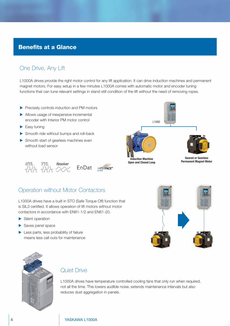
One Drive, Any Lift
L1000A drives provide the right motor control for any lift application. It can drive induction machines and permanent
magnet motors. For easy setup in a few minutes L1000A comes with automatic motor and encoder tuning
functions that can tune relevant settings in stand still condition of the lift without the need of removing ropes.
Precisely controls induction and PM motors
Allows usage of inexpensive incremental
encoder with Interior PM motor control
Easy tuning
Smooth ride without bumps and roll-back
Smooth start of gearless machines even
without load sensor
L1000A drives have a built in STO (Safe Torque Off) function that
is SIL3 certifi ed. It allows operation of lift motors without motor
contactors in accordance with EN81-1/2 and EN81-20.
Silent operation
Saves panel space
Less parts, less probability of failure
means less call outs for maintenance
Operation without Motor Contactors
L1000A drives have temperature controlled cooling fans that only run when required,
not all the time. This lowers audible noise, extends maintenance intervals but also
reduces dust aggregation in panels.
Quiet Drive
Resolver
Induction MachineOpen and Closed Loop
L1000
Geared or Gearless Permanent Magnet Motor

5
Open Controller Interface
Built-in LCD Interface for Simple Setup and Parameter Handling
Evacuation with UPS or Battery
The L1000A can easily be connected to almost any lift controller. The digital/analogue
inputs and outputs are freely programmable and pre-set to most likely confi gurations.
For an easy interface setup the drive provides signalling patterns for commonly used
controllers that can be switched with just a single parameter.
In addition serial protocols like DCP3, DCP4* and CANLift* are supported.
Flexible digital/analogue interface
Pre-settings for most common controllers simplifi es setup
Support of serial procolls DCP3, DCP4* and CANLift*
* in preparation
L1000A drives are shipped with a built-in LCD keypad with full text display in various
languages. For easy use the keypad can be taken off the unit and connected using a
standard RJ45 cable.
11 European languages
(English, German, French, Spanish, Italian, Portuguese, Greek, Turkish, Polish, Czech,
Russian)
Clear text display in lift terminology and units (m/s, m/s², ...)
Integrated backlight for good readability in dark environment
Parameter copy function for easy setup of lift with the same confi guration
Removable from main unit, usable with extension cable
L1000A provides several possibilities to evacuate trapped passengers quickly in case of a power
outage. It can be used with an uninterruptable power supply (UPS) or batteries and an automatic light
load search evacuates in the light load direction, allowing a “just fi t” selection of the UPS or battery
without a lot of over sizing.
Single or three-phase 230 Vac
UPS for 400 V drives
48 – 96 Vdc battery for main
circuit with 24 Vdc supply of
control circuit
Automatic evacuation in light
load direction
*For clarity, the illustrations have been simplified, omitting several switches and control signals.
230 Vsingle phase
48–96 VDC
24 VDC
UPS
24 V
power supply
unit
UPS wiring and operation Back-up battery wiring and operation

6 YASKAWA L1000A
Engineering Tools for YASKAWA Inverter Drives
All in one tool for parameter management, drive setup,
monitoring, and fault diagnostics
Convenient PC-based drive-setup, monitoring and
diagnostic functions
Built-in scope function
Online and offl ine parameter editing
L1000V
The compact YASKAWA L1000V is the
cost-effective solution for modernisations
and new installation of lifts with open
loop controlled geared motors. L1000V
drives cover a power range from 4 to
15 kW. Reduced to the essentials, this
drive combines easy setup, stable lift
performance and a durable, solid design.
D1000 - Low Harmonics Regenerative
Converter
With a D1000 converter braking energy can
be fed back to the grid instead of wasting it in
braking resistors. Especially for lifts with a high
number of travels this is the solution to achieve
maximum energy efficiency
The D1000 can be used for single and group lifts.
Tailored Motor-Drive Packages
With the combination of L1000A drives and
MSYP series gearless lift motors YASKAWA
offers packages for gearless lifts with loads up to
2500 kg and speeds up to 2 m/s. All component
have been selected and adjusted to provide
maximum ride comfort with minimum effort.
DriveWizard Plus for easy Engineering
Manage the unique settings for all your drives right on your PC. An indispensable tool for drive setup and
maintenance. Edit parameters, access all monitors, create customized operation sequences, and observe drive
performance with the oscilloscope function.
Also Available from YASKAWA: Als

7
Model Number
Model Number Keys for the L1000A Lift Inverter
200 VRated output current [A] Max. applicable motor [kW]
0008 8*1 1.5
0011 11*1 2.2
0018 18*1 4.0
0025 25*1 5.5
0033 33*1 7.5
0047 47*1 11
0060 60*1 15
0075 75*1 18.5
0085 85*1 22
0115 115*1 30
0145 145*2 37
0180 180*2 45
0215 215*2 55
0283 283*2 75
0346 346*2 90
0415 415*2 110
*1: This value assumes a maximum carrier frequency of 8 kHz. Increasing the carrier frequency requires a reduction in current.
*2: This value assumes a maximum carrier frequency of 5 kHz. Increasing the carrier frequency requires a reduction in current.
CIMR- L C 4 A 0015 B A A
AC Drive L1000A Series
Region CodeC Europe
Voltage Class2 3-phase, 200-240 Vac
4 3-phase, 380-480 Vac
Customized Specifi cationsA Standard model
F SIL3 STO built in
Enclosure TypeB IP20
C IP20 with reduced bending space
Special ModelBlank Standard
9100 A3 Brake Monitoring/DCP3 for LC4A
9130 A3 Brake Monitoring/DCP3 for LC4F
Environmental Specifi cationA Standard
400 VRated output current [A] Max. applicable motor [kW]
0005 4.8*1 1.5
0006 5.5*1 2.2
0009 9.2*1 4.0
0015 14.8*1 5.5
0018 18*1 7.5
0024 24*1 11
0031 31*1 15
0039 39*1 18.5
0045 45*1 22
0060 60*1 30
0075 75*1 37
0091 91*1 45
0112 112*2 55
0150 150*2 75
0180 180*2 90
0216 216*2 110
Revision Order
Op
era
tin
g
En
vir
on
me
nt
Po
we
r R
ati
ng
s
Specifi cations
Ambient Temperature −10 to +50 °C (open chassis), −10 to +40 °C (NEMA Type 1)
Humidity 95% RH or less (non condensating)
Storage Temperature -20 to +60 °C (short-term temperature during transportation)
Altitude Up to 1000 meters (output derating required above 1000 m, max. 3000 m)
Shock 10 Hz to 20 Hz, 9.8 m/s2 max. 20 Hz to 55 Hz, 5.9 m/s2 (200 V: 45 kW or more,
400 V: 55 kW or more) or 2.0 m/s2 max. (200 V: 55 kW or less, 400 V: 75 kW or less)
Protective Design IP20 Open Type enclosure
Standards CE, UL, cUL, RoHS
Functional Safety LC A: STO (Safe Torque Off) according to EN ISO 13849-1, Cat. 3, PL d; IEC EN 61508 SiL2
LC F: STO (Safe Torque Off) according to EN ISO 13849-1, Cat. 3, PL e; IEC EN 61508 SiL3*3
Overload Capability 150% for 1 minute
Rated Input Voltage 200 to 240 Vac 50/60 Hz (-15% to +10%), 380 to 480 Vac 50/60 Hz (-15% to +10%)
Rated Input Frequency 50/60 Hz ± 3%
Input Power Factor min. 0.98 (for rated operation)
Output Frequency Range 0 - 120 Hz
Starting Torque 150%/3 Hz (V/f Control), 200%/0.3 Hz (Open Loop Vector Control),
200%/0 r/min (Closed Loop Vector Control)
Braking Transistor Built-in up to 30 kW
*3: Available for 400 V models only

8 YASKAWA L1000A
Technical Data
Options & Accessories
Inp
ut
/ O
utp
ut
Mo
tor
Sp
ee
d
Fe
ed
ba
ck
Oth
ers
Co
mm
un
i-c
ati
on
Communication
Interface Unit
CANopen SI-S3
Analog Output 2 channel analog output option
−10 to +10 VDC (Res. 1/2048)
AO-A3
Digital Output 8 channel digital output option
6 photo couplers (48 V, 50 mA or less),
2 relay contact outputs max 250 Vac/30 Vdc, 1 A
DO-A3
Digital Input 1 channel digital input option
16 bit binary, 2 digit BCD + sign signal + set signal, +24 V (isolated), 8 mA
DI-A3
Open Collector Type Phase A, B, and Z pulse (complementary type), max. 50 kHz PG-B3
Line Driver Type Phase A, B, and Z pulse (differential pulse) (RS-422),
max. 300 kHz, pulse monitor output
PG-X3
Endat / Hiperface Endat 2.1/2.2, HIPERFACE PG-F3
Heidenhain sin/cos Heidenhain ERN1387 / ERN487 PG-E3
Resolver Resolver PG-RT3
USB Copy Unit USB converter for PC Tool usage and copy unit for easy parameter setup
duplication and backup in one
JVOP-181
IP65 Operator Mounting
Frame
Provides a simple way of installing the LCD Remote Operator of the drive on a
cabinet wall or door
EUOP-V11001
DriveWizard Plus Software used for parametrization
24 V Power Supply Provides power supply for the control circuit and option
boards when main circuit power is off
400 V class PS-A10HB
200 V class PS-A10LB
LCD Operator
Extension Cable
Cable for connecting the LCD operator WV001: 1 m
WV003: 3 m
Item Description Model Code
Item Description Model Code
Item Description Model Code
Item Description Model Code

9
Model CIMR-LC4
Standard EMC Filter
AC Input Reactor Braking Unit Braking ResistorIP00 IP20 CDBR
0005 FB-40008AB 1103136 B 0903088
built in
–0006
FB-40014A0009 RH-1000W120
0015FB-40025A B 1103138 B 0903089
RH-1560W040
0018 RH-2700W025
0024FB-40044A
B 1103139 B 0903090 RH-3700W025
0031 B 1103140 B 0903091 RH-4800W022
0039FB-40060A B 1103141 B 0910014
RH-4800W022
0045 RH-6000W022
0060 FB-40072A B 1103142 B 0910016 RH-7500W023
0075FB-40105A
B 1103142 B 09100164045D RH-9600W015
0091 B 0910013 B 0910018
0112FB-40170A
B 0910013 B 0910018 2× 4030D 2× RH-6000W022
0150– – – –0180
FB-40250A0216
Model CIMR-LC2A
Standard EMC Filter
AC Input Reactor Braking UnitCDBRIP00 IP20
0008FB-40014A LR3 40-4/16 LR3 40-4/16-IP20
–
00110018 FB-40025A LR3 40-4/20 LR3 40-4/20-IP20
0025FB-40060A
LR3 40-4/45 LR3 40-4/45-IP2000330047
LR3 40-4/70 LR3 40-4/70-IP200060 FB-40072A0075 FB-40105A LR3 40-4/90
LR3 40-4/90-IP200085
FB-40170ALR3 40-4/115
0115 LR3 40-4/115-IP20
0145 LR3 40-4/160 LR3 40-4/160-IP20 2037D
0180 FB-40250A LR3 40-4/200 LR3 40-4/200-IP20 2× 2022D
0215FB-40414A
LR3 40-4/250 LR3 40-4/250-IP20
–02830346
LR3 40-4/400 LR3 40-4/400-IP200415 FB-40675A
400 V Class
200 V Class
EMC Filter & AC Input Reactor
EMC fi lters and AC reactors are installed at
the input of the drive. They reduce conducted
emission and harmonic distortion in order to
maintain compliance with EMC standards such
as the EN12015.
Braking Options
Braking options dissipate kinetic energy when
moving in regenerative direction. Drives up to 30
kW have built-in braking transistors and must only
be equipped with a braking resistor. Larger drives
need an additional braking unit.
EMC and Braking Options

10 YASKAWA L1000A
L1000 Dimensions and Weights
W1
HH1
H2W
DD1
t1
4-d
H2
W1
HH0
H1
WD1
Dt1
H3
4-d
H1
H2
H0
H3
H
W1
W DD1
t24-d
Max 10Max 10
Fig. 1 Fig. 2 Fig. 3
400 V Class
IP20*
Model CIMR- LC4
Max. applicable motor capacity [kW]
Fig. IP20Dimensions [mm] Weight
[kg]W H D W1 H0 H1 H2 H3 D1 t1 t2 d0005 1.5
Fig. 1
140 260
147
122
-
248 6
-
38
5 -M5
3.2
0006 2.2164
55
3.4
0009 4.0 3.5
0015 5.5167
3.90018 7.50024 11
180 300 160 2848
5.4
0031 15 187 75 5.7
0039 18.5 220 350 197 192 335 78
M6
8.3
0045 22
Fig. 3
254 465 258 195 400 385
7.5
65 100
2.3
23
0060 30 279 515 258 220 450 435 27
0075 37
329
630 258
260
510 495 120 105 390091 450112 55
730 283 550 535 180 11043
0150 75 45
0180 90 450 705 330 325 705 680 12.5 163130
3.2 M10 85
0216 110 500 800 350 370 800 773 13 236 4.5 M12 103
Note: * with reduced bending space IP20 compliant standard enclosure IP20 compliant enclosure with reduced bending space
Model CIMR- LC2A
Max. applicable motor capacity [kW]
Fig. IP20Dimensions [mm] Weight
[kg]W H D W1 H0 H1 H2 H3 D1 t1 t2 d0008 1.5
Fig. 1
140 260
147
122
-
248 6
-
38
5 -
M5
3.20011 2.2
0018 4.0 164
55
3.5
0025 5.5167 4.0
0033 7.50047 11 180 300 187 160 284
8
75 5.6
0060 15220
350197 192 335 78
M6
8.7
0075 18.5 Fig. 2 365 350 15 9.7
0085 22
Fig. 3
254 534258
195 400 385
7.5
134100
2.3 2.3
23
0115 30 279 614 220 450 435 164 28
0145 37329 630 283 260 550 535 80 110 40
0180 450215 55
450 705 330 325 705 680 12.5 163
130
3.2 3.2 M1081
0283 75 86
0346 90500 800 350 370 800 773 13 238 4.5 4.5 M12 105
0415 110
200 V Class
Technical Data
11
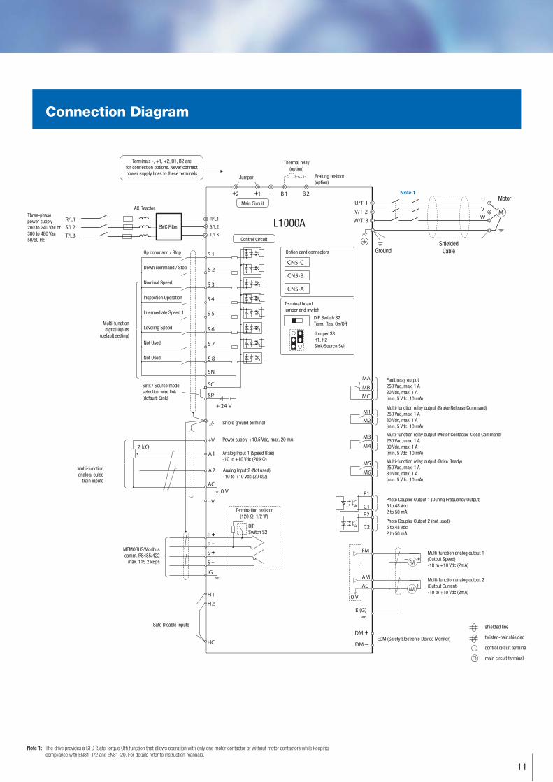
Note 1: The drive provides a STO (Safe Torque Off) function that allows operation with only one motor contactor or without motor contactors while keeping
compliance with EN81-1/2 and EN81-20. For details refer to instruction manuals.
CN5-C
CN5-B
CN5-A
R/L1S/L2
T/L3
P1
P2C1
C2
+
+
+
++
M
U/T 1V/T 2W/T
U
VW3
+
+
+
++
+
S 1
S 2
S 3
S 4
S 5
S 6
S 7
DM
DM
A1
A2
0 VAC
R
R
S
S
IG
H1
H2
HC
B 112 B 2
2 kΩ
S 8
SC
0 V
FM
AMAC
E (G)
+ 24 V
+V
MA
M1M2
MBMC
−V
R/L1
S/L2
T/L3
M3M4
M5M6
SP
SN
FM
+AM
Thermal relay
(option)
EMC Filter
AC Reactor
L1000A
Braking resistor
(option)
Nominal Speed
Inspection Operation
Intermediate Speed 1
Leveling Speed
Not Used
Not Used
Down command / Stop
Up command / Stop
Terminals -, +1, +2, B1, B2 are
for connection options. Never connect
power supply lines to these terminalsJumper
Main Circuit
Control Circuit
Motor
Ground
Fault relay output
250 Vac, max. 1 A
30 Vdc, max. 1 A
(min. 5 Vdc, 10 mA)
Shield ground terminal
Power supply +10.5 Vdc, max. 20 mA
Analog Input 1 (Speed Bias)
-10 to +10 Vdc (20 kΩ)
Analog Input 2 (Not used)
-10 to +10 Vdc (20 kΩ)
Multi-function relay output (Brake Release Command)
250 Vac, max. 1 A
30 Vdc, max. 1 A
(min. 5 Vdc, 10 mA)
Multi-function relay output (Motor Contactor Close Command)
250 Vac, max. 1 A
30 Vdc, max. 1 A
(min. 5 Vdc, 10 mA)
Multi-function relay output (Drive Ready)
250 Vac, max. 1 A
30 Vdc, max. 1 A
(min. 5 Vdc, 10 mA)
Shielded
Cable
Multi-function analog output 1
(Output Speed)
-10 to +10 Vdc (2mA)
Multi-function analog output 2
(Output Current)
-10 to +10 Vdc (2mA)
shielded line
twisted-pair shielded
control circuit termina
main circuit terminal
EDM (Safety Electronic Device Monitor)
Safe Disable inputs
MEMOBUS/Modbus
comm. RS485/422
max. 115.2 kBps
Multi-function
analog/ pulse
train inputs
Multi-function
digtial inputs
(default setting)
Sink / Source mode
selection wire link
(default: Sink)
Three-phase
power supply
200 to 240 Vac or
380 to 480 Vac
50/60 Hz
Termination resistor
(120 Ω, 1/2 W)
DIP Switch S2
Term. Res. On/Off
Jumper S3
H1, H2
Sink/Source Sel.
DIP
Switch S2
Note 1
Option card connectors
Terminal board
jumper and switch
Photo Coupler Output 1 (During Frequency Output)
5 to 48 Vdc
2 to 50 mA
Photo Coupler Output 2 (not used)
5 to 48 Vdc
2 to 50 mA
Connection Diagram
Specifications are subject to change without notice
for ongoing product modifications and improvements.
© YASKAWA Europe GmbH. All rights reserved.
Literature No. YEU_INV_L1000A_EN_v7_0715Printed in Germany, July 2015
YASKAWA Europe GmbH
Drives & Motion Division
Hauptstr. 185
65760 Eschborn
Germany
+49 6196 569-500
www.yaskawa.eu.com