kst101 k-cube stepper motor controller apt user guide · the k-cube stepper motor controller...
TRANSCRIPT
KST101K-Cube Stepper Motor Controller
APT User Guide
Original Instructions

Contents
Chapter 1 Safety ............................................................................................. 41.1 Safety Information .................................................................................. 41.2 General Warnings .................................................................................. 4
Chapter 2 Overview and Setup ..................................................................... 52.1 Introduction ............................................................................................. 52.2 K-Cube Controller Hub ........................................................................... 62.3 APT PC Software Overview ................................................................... 72.3.1 Introduction ......................................................................................................... 72.3.2 APTUser Utility ................................................................................................... 82.3.3 APT Config Utility ............................................................................................... 92.3.4 APT Server (ActiveX Controls) ......................................................................... 102.3.5 Software Upgrades ........................................................................................... 11
Chapter 3 Getting Started ............................................................................ 123.1 Install The Software .............................................................................. 123.2 Mechanical Installation ......................................................................... 133.3 Electrical Installation ............................................................................. 143.4 Connect The Hardware ........................................................................ 163.5 Use with Legacy Actuators and Stages ................................................ 173.6 Verifying Software Operation ............................................................... 18
Chapter 4 Standalone Operation ................................................................ 204.1 Introduction ........................................................................................... 204.2 Control Panel ....................................................................................... 214.2.1 Digital Display - Operating Mode ...................................................................... 214.3 Velocity Wheel Operation ..................................................................... 224.3.1 Homing ............................................................................................................. 224.3.2 Go to Position ................................................................................................... 224.3.3 Jogging ............................................................................................................. 224.3.4 Velocity Moves ................................................................................................. 234.4 Settings Menu ...................................................................................... 234.4.1 Overview .......................................................................................................... 234.4.2 Menu Option - Go to position ........................................................................... 244.4.3 Menu Option - Start homing ............................................................................. 254.4.4 Menu Option - Velocity ..................................................................................... 254.4.5 Menu Option - Joystick Mode ........................................................................... 264.4.6 Menu Option - Jog Step Size ........................................................................... 274.4.7 Menu Option - Teach Position .......................................................................... 284.4.8 Menu Option - Brightness ................................................................................. 294.4.9 menu Option - Disp.Level.................................................................................. 294.4.10 Menu Option - Disable ...................................................................................... 304.4.11 Menu Option - Select stage .............................................................................. 31
Continued...
2 HA0362T Rev C Jan 2017

K-Cube Stepper Motor Controller
Chapter 5 PC Operation - Tutorial ............................................................. 325.1 Introduction ........................................................................................... 325.2 Using the APT User Utility .................................................................... 325.3 Homing Motors ..................................................................................... 345.4 Moving to an Absolute Position ............................................................ 355.5 Changing Motor Parameters ................................................................ 365.6 Jogging ................................................................................................. 375.7 Stopping the Stage ............................................................................... 385.8 Graphical Control Of Motor Positions (Point and Move) ....................... 395.9 Setting Move Sequences ...................................................................... 415.10 Creating a Simulated Configuration Using APT Config ........................ 445.11 Stage/Axis Tab ..................................................................................... 47
Chapter 6 Software Reference .................................................................... 486.1 Introduction ........................................................................................... 486.2 GUI Panel ............................................................................................. 486.3 Settings Panel ...................................................................................... 506.3.1 Moves/Jogs Tab ............................................................................................... 506.3.2 Stage/Axis Tab ................................................................................................. 556.3.3 Panel/Triggering Tab ....................................................................................... 586.3.4 Rotation StagesTab ......................................................................................... 63
Appendices
Appendix A Rear Panel Connector Pinout Details .................................... 64
Appendix B Preventive Maintenance ......................................................... 65
Appendix C Specifications .......................................................................... 66
Appendix D Motor Control Method Summary ........................................... 68
Appendix E Stepper Motor Operation - Background ................................ 72
Appendix F Regulatory ................................................................................ 78
Appendix G Thorlabs Worldwide Contacts ............................................... 81
3
Chapter 1 Safety
1.1 Safety Information
For the continuing safety of the operators of this equipment, and the protection of theequipment itself, the operator should take note of the Warnings, Cautions and Notesthroughout this handbook and, where visible, on the product itself.
The following safety symbols may be used throughout the handbook and on theequipment itself.
1.2 General Warnings
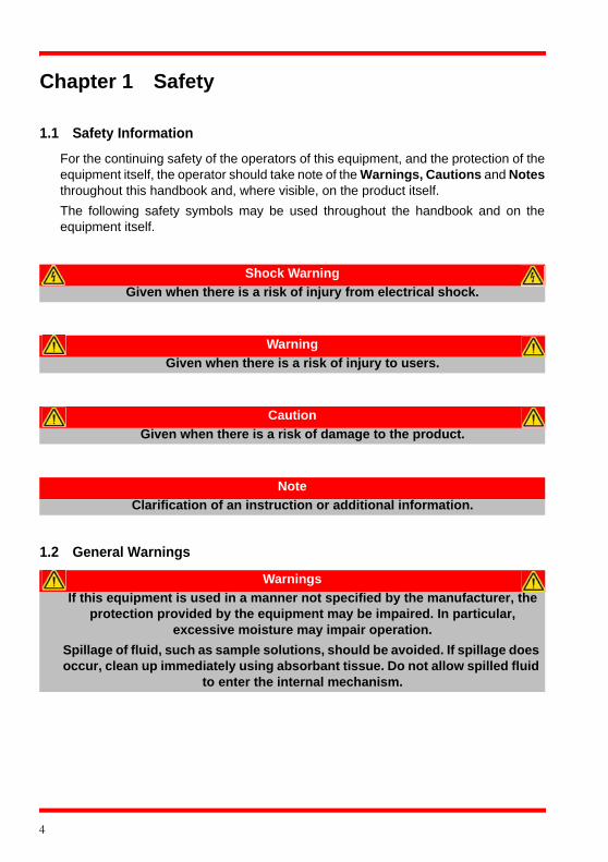
Shock Warning
Given when there is a risk of injury from electrical shock.
Warning
Given when there is a risk of injury to users.
Caution
Given when there is a risk of damage to the product.
Note
Clarification of an instruction or additional information.
Warnings
If this equipment is used in a manner not specified by the manufacturer, the protection provided by the equipment may be impaired. In particular,
excessive moisture may impair operation.
Spillage of fluid, such as sample solutions, should be avoided. If spillage does occur, clean up immediately using absorbant tissue. Do not allow spilled fluid
to enter the internal mechanism.
4
Chapter 2 Overview and Setup
2.1 Introduction
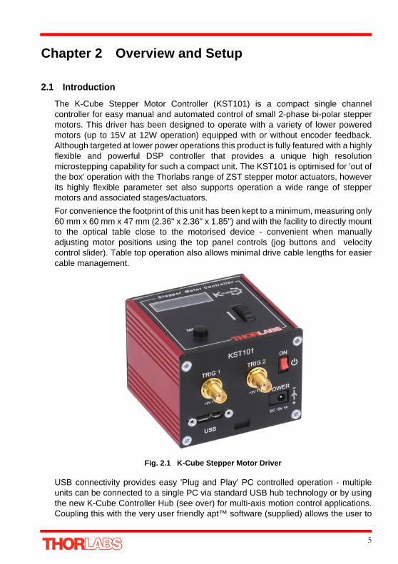
The K-Cube Stepper Motor Controller (KST101) is a compact single channelcontroller for easy manual and automated control of small 2-phase bi-polar steppermotors. This driver has been designed to operate with a variety of lower poweredmotors (up to 15V at 12W operation) equipped with or without encoder feedback.Although targeted at lower power operations this product is fully featured with a highlyflexible and powerful DSP controller that provides a unique high resolutionmicrostepping capability for such a compact unit. The KST101 is optimised for 'out ofthe box' operation with the Thorlabs range of ZST stepper motor actuators, howeverits highly flexible parameter set also supports operation a wide range of steppermotors and associated stages/actuators.
For convenience the footprint of this unit has been kept to a minimum, measuring only60 mm x 60 mm x 47 mm (2.36" x 2.36" x 1.85") and with the facility to directly mountto the optical table close to the motorised device - convenient when manuallyadjusting motor positions using the top panel controls (jog buttons and velocitycontrol slider). Table top operation also allows minimal drive cable lengths for easiercable management.
Fig. 2.1 K-Cube Stepper Motor Driver
USB connectivity provides easy 'Plug and Play' PC controlled operation - multipleunits can be connected to a single PC via standard USB hub technology or by usingthe new K-Cube Controller Hub (see over) for multi-axis motion control applications.Coupling this with the very user friendly apt™ software (supplied) allows the user to
5

Chapter 2
very quickly get up and running with complex move sequences in a short space oftime – for example all relevant operating parameters are set automatically forThorlabs stage/actuator products. Advanced custom motion control applications andsequences are also possible using the extensive ActiveX® programming environmentalso supplied. This programming library is compatible with many development toolssuch as LabView, Visual Basic, Visual C++, C++ Builder, LabWindows/CVI, Matlaband Delphi.
In the remainder of this handbook, operation of the unit is described for both frontpanel and PC operation. Tutorial sections (Chapter 4 and Chapter 5) provide a goodinitial understanding on using the unit and reference section (Chapter 6) covers alloperating modes and parameters in detail.
2.2 K-Cube Controller Hub
For power, a single way wall plug supply (KPS101) is available for powering a singleK-Cube Driver.
As a further level of convenience when using the new K-Cube Controllers Thorlabsalso offers the 3-channel and 6-channel K-Cube Controller Hubs (KCH301 andKCH601). These products have been designed specifically with multiple K-Cubeoperation in mind in order to simplify issues such as cable management, powersupply routing, multiple USB device communications and different optical tablemounting scenarios.
The K-Cube Controller Hub comprises a slim base-plate type carrier with electricalconnections located on the upper surface to accept the K-Cubes.
Internally the Controller Hub contains a fully compliant USB 2.0 hub circuit to providecommunications for all K-Cubes – a single USB connection to the Controller Hub isall that is required for PC control. The Controller Hub also provides power distributionfor the K-Cubes, requiring only a single power connection.
6 HA0362T Rev C Jan 2017

K-Cube Stepper Motor Controller
2.3 APT PC Software Overview
2.3.1 IntroductionAs a member of the APT range of controllers, the Stepper Driver K-Cube shares manyof the associated software benefits. This includes USB connectivity (allowing multipleunits to be used together on a single PC), fully featured Graphical User Interface(GUI) panels, and extensive software function libraries for custom applicationdevelopment.
The APT software suite supplied with all APT controllers, including the Stepper DriverK-Cube, provides a flexible and powerful PC based control system both for users ofthe equipment, and software programmers aiming to automate its operation.
For users, the APTUser (see Section 2.3.2.) and APTConfig (see Section 2.3.3.)utilities allow full control of all settings and operating modes enabling complete ‘out-of-box’ operation without the need to develop any further custom software. Bothutilities are built on top of a sophisticated, multi-threaded ActiveX ‘engine’ (called theAPT server) which provides all of the necessary APT system software services suchas generation of GUI panels, communications handling for multiple USB units, andlogging of all system activity to assist in hardware trouble shooting. It is this APTserver ‘engine’ that is used by software developers to allow the creation of advancedautomated positioning applications very rapidly and with great ease. The APT serveris described in more detail in Section 2.3.4.
Aside
ActiveX®, a Windows®-based, language-independent technology, allows a userto quickly develop custom applications that automate the control of APT systemhardware units. Development environments supported by ActiveX® technologyinclude Visual Basic®, LabView™, Borland C++ Builder, Visual C++, Delphi™,and many others. ActiveX® technology is also supported by .NET developmentenvironments such as Visual Basic.NET and Visual C#.NET.
ActiveX controls are a specific form of ActiveX technology that provide both a userinterface and a programming interface. An ActiveX control is supplied for eachtype of APT hardware unit to provide specific controller functionality to thesoftware developer. See Section 2.3.4. for further details.
7

Chapter 2
2.3.2 APTUser UtilityThe APTUser application allows the user to interact with a number of APT hardwarecontrol units connected to the host PC. This program displays multiple graphicalinstrument panels to allow multiple APT units to be controlled simultaneously.
All basic operating parameters can be altered and, similarly, all operations (such asmotor moves) can be initiated. Settings and parameter changes can be saved andloaded to allow multiple operating configurations to be created and easily applied.
For many users, the APTUser application provides all of the functionality necessaryto operate the APT hardware without the need to develop any further customsoftware. For those who do need to further customise and automate usage of theStepper Driver K-Cube (e.g. to implement a positioning algorithm), this applicationillustrates how the rich functionality provided by the APT ActiveX server is exposedby a client application.
Use of the APT User utility is covered in the PC tutorial (Chapter 5) and in theAPTUser online help file, accessed via the F1 key when using the APTUser utility.
8 HA0362T Rev C Jan 2017

K-Cube Stepper Motor Controller
2.3.3 APT Config UtilityThere are many system parameters and configuration settings associated with theoperation of the APT Server. Most can be directly accessed using the variousgraphical panels, however there are several system wide settings that can be made'off-line' before running the APT software. These settings have global effect; such asswitching between simulator and real operating mode, associating mechanical stagesto specific motor actuators and incorporation of calibration data.
The APTConfig utility is provided as a convenient means for making these systemwide settings and adjustments. Full details on using APTConfig are provided in theonline help supplied with the utility.
Use of the APT Config utility is covered in the PC tutorial (Chapter 5) and in theAPTConfig online help file, accessed via the F1 key when using the APTConfig utility.
9

Chapter 2
2.3.4 APT Server (ActiveX Controls)ActiveX Controls are re-usable compiled software components that supply both agraphical user interface and a programmable interface. Many such Controls areavailable for Windows applications development, providing a large range of re-usablefunctionality. For example, there are Controls available that can be used tomanipulate image files, connect to the internet or simply provide user interfacecomponents such as buttons and list boxes.
With the APT system, ActiveX Controls are deployed to allow direct control over (andalso reflect the status of) the range of electronic controller units, including the StepperDriver K-Cube. Software applications that use ActiveX Controls are often referred toas 'client applications'. Based on ActiveX interfacing technology, an ActiveX Controlis a language independent software component. Consequently ActiveX Controls canbe incorporated into a wide range of software development environments for use byclient application developers. Development environments supported include VisualBasic, Labview, Visual C++, C++ Builder, HPVEE, Matlab, VB.NET, C#.NET and, viaVBA, Microsoft Office applications such as Excel and Word.
Consider the ActiveX Control supplied for the KST101 stepper driver unit.
This Control provides a complete user graphical instrument panel to allow the motorunit to be manually operated, as well as a complete set of software functions (oftencalled methods) to allow all parameters to be set and motor operations to beautomated by a client application. The instrument panel reflects the current operatingstate of the controller unit to which it is associated (e.g. such as motor position).Updates to the panel take place automatically when a user (client) application ismaking software calls into the same Control. For example, if a client applicationinstructs the associated stepper motor Control to move a motor, the progress of thatmove is reflected automatically by changing position readouts on the graphicalinterface, without the need for further programming intervention.
10 HA0362T Rev C Jan 2017

K-Cube Stepper Motor Controller
The APT ActiveX Controls collection provides a rich set of graphical user panels andprogrammable interfaces allowing users and client application developers to interactseamlessly with the APT hardware. Each of the APT controllers has an associatedActiveX Control and these are described fully in system online help or the handbooksassociated with the controllers. Note that the APTUser and APTConfig utilities takeadvantage of and are built on top of the powerful functionality provided by the APTActiveX Server (as shown in Fig. 2.2).
Fig. 2.2 System Architecture Diagram
Refer to the main APT Software online help file for a complete programmers guideand reference material on using the APT ActiveX Controls collection. This is availableeither by pressing the F1 key when running the APT server, or via the Start menu,Start\Programs\Thorlabs\APT\APT Help.
2.3.5 Software UpgradesThorlabs operate a policy of continuous product development and may issue softwareupgrades as necessary.
11

Chapter 3 Getting Started
3.1 Install The Software
DO NOT CONNECT THE CONTROLLER TO YOUR PC YET
1) Download the software from www.thorlabs.com.
2) Locate the downloaded setup.exe file and move to a suitable file location.
3) Double-click the setup.exe file and follow the on-screen instructions.
Note
When operating via a PC, direct user interaction with the unit is accomplished through intuitive graphical user interface panels (GUIs), which expose all key operating parameters and modes. The user can select multiple panel views displaying different information about a
particular hardware unit. The multitasking architecture ensures that the graphical control panels always remain live, showing all current
hardware activity.
Caution
Some PCs may have been configured to restrict the users ability to load software, and on these systems the software may not install/run. If you are in any doubt about your rights to install/run software, please consult your
system administrator before attempting to install.
If you experience any problems when installing software, contact Thorlabs on +44 (0)1353 654440 and ask for Technical Support.
12

K-Cube Stepper Motor Controller
3.2 Mechanical Installation
3.2.1 Environmental Conditions
Location Indoor use only
Maximum altitude 2000 m
Temperature range 5oC to 40oC
Maximum Humidity Less than 80% RH (non-condensing) at 31°C
To ensure reliable operation the unit should not be exposed to corrosive agents orexcessive moisture, heat or dust.
If the unit has been stored at a low temperature or in an environment of high humidity,it must be allowed to reach ambient conditions before being powered up.
3.2.2 Mounting OptionsThe K-Cube Stepper Driver is shipped with a baseplate, for use when fitting the unitto a breadboard, optical table or similar surface - see Section 3.2.3.
For multiple cube systems, a 3-channel and 6-channel K-Cube Controller Hub(KCH301 and KCH601). ) are also available - see Section 2.2. for further details. Fullinstructions on the fitting and use of the controller hub are contained in the handbookavailable at www.thorlabs.com.
Caution
This unit is designed for operation within normal operational limits. It is not recommended to use this equipment outside the following limits.
Caution
When siting the unit, it should be positioned so as not to impede the operation of the control panel.
Ensure that proper airflow is maintained to the unit.
13
Chapter 3
3.2.3 Using the BaseplateThe baseplate must be bolted to the worksurface before the K-Cube is fitted, as shown below.The K-cube is then located on two dowels in the baseplate and secured by two clips.
Fig. 3.1 Using The Baseplate
3.3 Electrical Installation
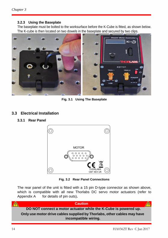
3.3.1 Rear Panel
Fig. 3.2 Rear Panel Connections
The rear panel of the unit is fitted with a 15 pin D-type connector as shown above,which is compatible with all new Thorlabs DC servo motor actuators (refer toAppendix A for details of pin outs).
Caution
DO NOT connect a motor actuator while the K-Cube is powered up.
Only use motor drive cables supplied by Thorlabs, other cables may have incompatible wiring.
14 HA0362T Rev C Jan 2017

K-Cube Stepper Motor Controller
3.3.2 Front Panel
Fig. 3.3 Front Panel Power Supply Connections
POWER - A Standard 3.5 mm front panel jack connector for connecting the unit to aregulated DC power supply of 15 V, 1A.
Thorlabs offers a compact, multi-way power supply unit (TPS008), allowing up toeight Driver K-Cubes to be powered from a single mains outlet. A single way wall plugsupply (KPS101) for powering a single Driver K-Cube is also available.
USB - USB port for system communications.
ON - Power ON/Standby switch. When in the ON position, the unit is fully poweredup. When the switch is turned to the Standby position, the unit initiates a controlledpower down sequence, saving all user-adjustable parameters to non-volatile memorybefore turning off the power. For the first few seconds, the shutdown can be cancelledby turning the switch on again, in which case the unit will save the parameters but willremain powered up. In a powered down (Standby) state, the logic circuits arepowered off and the unit will draw only a small quiescent current. The switch shouldalways be used to power down the unit.
TRIG 1 and TRIG 2 - SMA connectors for use with external trigger input and outputsignals (5V TTL levels). The function is set to trigger IN or OUT via the settings panel- see Section 6.3.3.
Shock Warning
The unit must be connected only to a DC supply of 15V, 1A regulated. Connection to a supply of a different rating may cause damage to the unit
and could result in injury to the operator.
Note
The USB cable length should be no more than 3 metres unless a powered USB hub is being used.
_
+
TRIG 1 TRIG 2
USB
POWER
DC 15V 1A
+5V TTL +5V TTL
ON
KST101
15

Chapter 3
3.4 Connect The Hardware
1) Perform the mechanical installation as detailed in Section 3.2.
2) Install the APT Software.
3) Connect the Controller unit to your PC.(Note. The USB cable should be no more than 3 metres in length. Communicationlengths in excess of 3 metres can be achieved by using a powered USB hub)
4) Connect the stepper motor actuator to the Controller unit - see Section 3.3.1..
5) Connect the Controller unit to the power supply - see Section 3.3.
6) Connect the PSU to the main supply.
7) Switch ‘ON’ the unit using the switch on the front panel.
The unit takes about 5 seconds from power application until warm up is finished,during which time the following screens are displayed.
Fig. 3.4 KST101 start up screens
8) WindowsTM should detect the new hardware. Wait while WindowsTM installs thedrivers for the new hardware.
Caution
During items (3) to (6) the instructions should be followed in the order stated. Problems may occur if the process is not performed in the correct sequence.
Caution
During item (5) ensure the power switch on the front panel of the unit is switched off before connecting power to the K-Cube. Always power up the K-Cube unit by its ON switch. DO NOT connect the K-Cube unit to a
'live' external power supply. Doing so (i.e. “hot plugging”) carries the risk of PERMANENT damage to the unit. Similarly, to power down the unit,
turn the power switch off before disconnecting the power supply.
Note
If any problems are encountered during the connection and power up process, power cycle the unit, which should clear the error.
T h o r l a b s K S T 1 0 1S w R e v 1 0 0 0 1
S t a g e C o n n e c t e d :Z F S 2 5
A t + 0 . 0 0 0 0 m mS t o p p e d V
16 HA0362T Rev C Jan 2017
K-Cube Stepper Motor Controller
3.5 Use with Legacy Actuators and Stages
To ensure that a particular stage is driven properly by the system, a number ofparameters must first be set. These parameters relate to the physical characteristicsof the stage being driven (e.g. min and max positions, leadscrew pitch, homingdirection etc.).
Later version actuators and stages have an identification eprom fitted such that thesystem will recognise the actuator type and install suitable defaults. Older versiondevices must be associated manually using the top panel menu - see Section 4.4.11.Once this association has been made, the APT server applies automatically, suitabledefault parameter values on boot up of the software.
Note
If the actuator/stage has been recognised automatically via the eprom, the start up screens will display ‘Stage connected xxxx’ as shown in Fig. 3.4. If the stage is not fitted with an eprom, the display will show the last
stage type persisted, e.g. Stage persisted: ZST13B
17
Chapter 3
3.6 Verifying Software Operation
3.6.1 Initial SetupThe APT Software should be installed (Section 3.1.) and the stage associationperformed (Section 3.5.) before software operation can be verified.
1) Ensure power is applied to the unit, then switch the unit ON using the switch onthe front panel.
2) If required, make the stage/actuator association as detailed in Section 4.4.11.
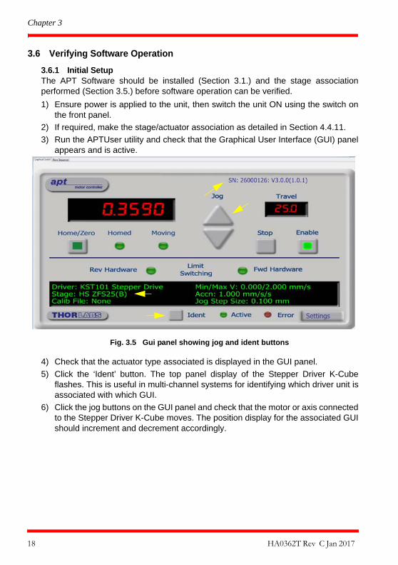
3) Run the APTUser utility and check that the Graphical User Interface (GUI) panelappears and is active.
Fig. 3.5 Gui panel showing jog and ident buttons
4) Check that the actuator type associated is displayed in the GUI panel.
5) Click the ‘Ident’ button. The top panel display of the Stepper Driver K-Cubeflashes. This is useful in multi-channel systems for identifying which driver unit isassociated with which GUI.
6) Click the jog buttons on the GUI panel and check that the motor or axis connectedto the Stepper Driver K-Cube moves. The position display for the associated GUIshould increment and decrement accordingly.
18 HA0362T Rev C Jan 2017
K-Cube Stepper Motor Controller
Follow the tutorial steps described in Chapter 4 for further verification of operation.’
Note
The 'APT Config' utility can be used to set up simulated hardware configurations and place the APT Server into simulator mode. In this way
it is possible to create any number and type of simulated (virtual) hardware units in order to emulate a set of real hardware. This is a
particularly useful feature, designed as an aid to application program development and testing. Any number of 'virtual' control units are
combined to build a model of the real system, which can then be used to test the application software offline. If using real hardware, ensure that
Simulator Mode is disabled. If using a simulated setup, enable Simulator Mode and set up a ‘Simulated Configuration’ - see Section 5.8. or the
APTConfig helpfile for detailed instructions.
19

Chapter 4 Standalone Operation
4.1 Introduction
The Stepper Driver K-Cube has been designed specifically to operate with lowerpower stepper motors such as the Thorlabs ZST series, however it can also drive avariety of other stepper motors (15V operation) equipped with or without encoderfeedback.
The unit offers a fully featured motion control capability including velocity profilesettings, limit switch handling, homing sequences and, for more advanced operation,adjustment of settings such as lead screw pitch and gearbox ratio, allowing supportfor many different actuator configurations. These parameters can be set via the APTServer software - see Chapter 5. Furthermore, when used with the extensive rangeof Thorlabs ZST motorised opto-mechanical products, many of these parameters areautomatically set to allow “out of the box” operation with no further “tuning” required.
The following brief overview explains how the front panel controls can be used toperform a typical series of motor moves.
In conjunction with this chapter, it also may be useful to read the background onstepper motor operation contained in Appendix E .
4.2 Control Panel
Fig. 4.1 Front Panel Controls and Indicators
MOVE Controls - These controls allow all motor moves to be initiated.
Velocity Wheel - Used to drive the motor at a varying speed in either forward orreverse directions for full and easy motor control - see Section 4.3.
Stepper Motor Controller
MENU
20
K-Cube Stepper Motor Controller
Digital Display - The display shows the menu options and settings, accessed viathe menu button - see Section 4.4. When the Ident button on the associated GUIpanel is clicked, the display will flash for a short period.
MENU - used to access the settings menu - see Section 4.4. Also used to stop amove when the stage is in motion.
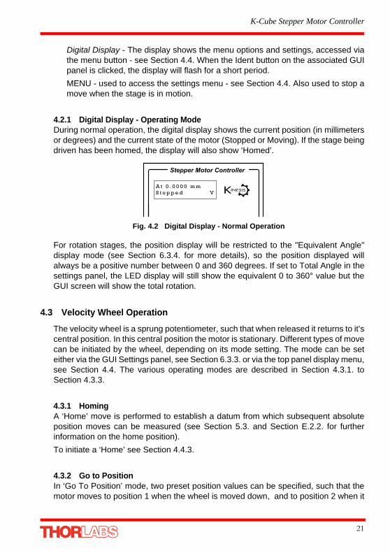
4.2.1 Digital Display - Operating ModeDuring normal operation, the digital display shows the current position (in millimetersor degrees) and the current state of the motor (Stopped or Moving). If the stage beingdriven has been homed, the display will also show ‘Homed’.
Fig. 4.2 Digital Display - Normal Operation
For rotation stages, the position display will be restricted to the "Equivalent Angle"display mode (see Section 6.3.4. for more details), so the position displayed willalways be a positive number between 0 and 360 degrees. If set to Total Angle in thesettings panel, the LED display will still show the equivalent 0 to 360° value but theGUI screen will show the total rotation.
4.3 Velocity Wheel Operation
The velocity wheel is a sprung potentiometer, such that when released it returns to it’scentral position. In this central position the motor is stationary. Different types of movecan be initiated by the wheel, depending on its mode setting. The mode can be seteither via the GUI Settings panel, see Section 6.3.3. or via the top panel display menu,see Section 4.4. The various operating modes are described in Section 4.3.1. toSection 4.3.3.
4.3.1 HomingA ‘Home’ move is performed to establish a datum from which subsequent absoluteposition moves can be measured (see Section 5.3. and Section E.2.2. for furtherinformation on the home position).
To initiate a ‘Home’ see Section 4.4.3.
4.3.2 Go to PositionIn ‘Go To Position’ mode, two preset position values can be specified, such that themotor moves to position 1 when the wheel is moved down, and to position 2 when it
Stepper Motor Controller
A t 0 . 0 0 0 0 m mS t o p p e d V
21

Chapter 4
is moved up. These ‘taught’ positions can be set through the software GUI - seeSection 6.3.3. or via the display menu, see Section 4.4.7.
This mode of operation is enabled by setting the ‘Wheel Mode’ to ‘Go To Position’through the software GUI - see Section 6.3.3. or via the display menu, see Section4.4.5.
4.3.3 JoggingThe top panel wheel can also be configured to ‘jog’ the motor. This mode of operationis enabled by setting the ‘Wheel Mode’ parameter to ‘Jogging’ through the softwareGUI - see Section 6.3.3. or via the display menu, see Section 4.4.5.
Once set to this mode, the jogging parameters for the wheels are taken from the ‘Jog’parameters on the ‘Move/Jogs’ settings tab - see Section 6.3.1. or via the displaymenu, see Section 4.4.6.
4.3.4 Velocity MovesLastly, the wheel can be used to initiate a move at a specified velocity. As the wheelis moved away from the centre, the motor begins to move. Bidirectional control of themotor is possible by moving the wheel in both directions. The speed of the motorincreases by discrete amounts as a function of wheel deflection, up to a maximum asset in through the software GUI - see Section 6.3.3. or via the display menu, seeSection 4.4.4. The move stops when the wheel is returned to its centre position.
Note for Rotation Stage Users
If the current absolute position is outside the 0 to 360 degree range, then "go to position" will result in a move to the correct angular position within the
same 0..360 degree full turn "segment". This means that the move will always stay in the current full turn segment, and from this point of view it is not always
the quickest position move. For example, if you are at 350 degrees and you enter a "go to" position of 10 degrees, the stage will rotate anticlockwise 340
degrees and not clockwise 20 degrees.
22 HA0362T Rev C Jan 2017

K-Cube Stepper Motor Controller
4.4 Settings Menu
4.4.1 Overview
Press the MENU button
Use the wheel to scroll through the menu options
Press the MENU button to enter a particular option
Move the stage to an absolute position - see Section 4.4.2.
Move the stage to the Home position - see Section 4.4.3.
Set the Max Velocity - see Section 4.4.4.
Set the joystick wheel mode - see Section 4.4.5.
Set the Jog Step Size - see Section 4.4.6.
Set the teach positions - see Section 4.4.7.
Set the display brightness - see Section 4.4.8.
Set the display time out period - see Section 4.4.9.
Disable the wheel - see Section 4.4.10.
Set the stage being driven - see Section 4.4.11.
A t 0 . 0 0 0 0 m mS t o p p e d V
M e n u o p t i o n sU s e w h e e l
M e n u o p t i o n s1 G o t o p o s i t i o n
M e n u o p t i o n s2 S t a r t h o m i n g
M e n u o p t i o n s3 V e l o c i t y
M e n u o p t i o n s4 J o y s t i c k m o d e
M e n u o p t i o n s5 J o g s t e p s i z e
M e n u o p t i o n s6 T e a c h p o s i t i o n
M e n u o p t i o n s7 B r i g h t n e s s
M e n u o p t i o n s8 D i s p . T i m e o u t
M e n u o p t i o n s9 D i s a b l e
M e n u o p t i o n s1 0 S e l e c t S t a g e
MENU
23

Chapter 4
4.4.2 Menu Option - Go to positionThis mode is used to move to an absolute position.
Press the MENU button, then use the wheel to scrollthrough the menu options.
Press the MENU button to enter the Go to positionsoption.
Use the wheel to adjust the position value, (within thetravel range for linear stages, or 0 to 360 ° for rotationstages) then press the MENU button to store theselection.
Note for rotation stages. If the current absolute positionis outside the 0 to 360 degree range, then "go to position"will result in a move to the correct angular position withinthe same 0..360 degree full turn "segment". This meansthat the move will always stay in the current full turnsegment, and from this point of view it is not always thequickest position move. For example, if you are at 350degrees and you enter a "go to" position of 10 degrees,the stage will rotate anticlockwise 340 degrees and notclockwise 20 degrees.
The stage moves to the position entered, and the displayshows the change in position.
To stop the move, press the MENU button.
A t 0 . 0 0 0 0 m mS t o p p e d V
A t 2 . 0 0 0 0 m mS t o p p e d V
M e n u o p t i o n sU s e w h e e l
M e n u o p t i o n s1 G o t o p o s i t i o n
P = 0 . 0 0 m m a d j u s t P o s
MENU
24 HA0362T Rev C Jan 2017
K-Cube Stepper Motor Controller
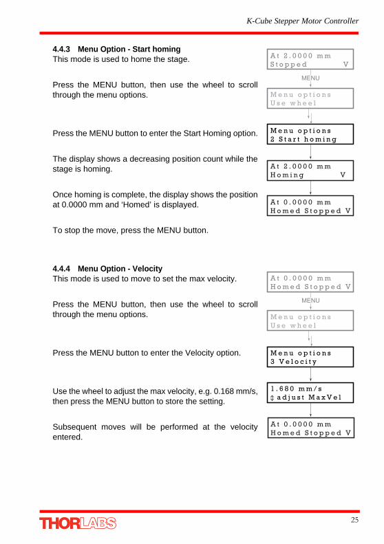
4.4.3 Menu Option - Start homingThis mode is used to home the stage.
Press the MENU button, then use the wheel to scrollthrough the menu options.
Press the MENU button to enter the Start Homing option.
The display shows a decreasing position count while thestage is homing.
Once homing is complete, the display shows the positionat 0.0000 mm and ‘Homed’ is displayed.
To stop the move, press the MENU button.
4.4.4 Menu Option - VelocityThis mode is used to move to set the max velocity.
Press the MENU button, then use the wheel to scrollthrough the menu options.
Press the MENU button to enter the Velocity option.
Use the wheel to adjust the max velocity, e.g. 0.168 mm/s,then press the MENU button to store the setting.
Subsequent moves will be performed at the velocityentered.
M e n u o p t i o n s2 S t a r t h o m i n g
A t 2 . 0 0 0 0 m mS t o p p e d V
M e n u o p t i o n sU s e w h e e l
MENU
A t 2 . 0 0 0 0 m mH o m i n g V
A t 0 . 0 0 0 0 m mH o m e d S t o p p e d V
A t 0 . 0 0 0 0 m mH o m e d S t o p p e d V
M e n u o p t i o n sU s e w h e e l
M e n u o p t i o n s3 V e l o c i t y
1 . 6 8 0 m m / s a d j u s t M a x V e l
MENU
A t 0 . 0 0 0 0 m mH o m e d S t o p p e d V
25
Chapter 4
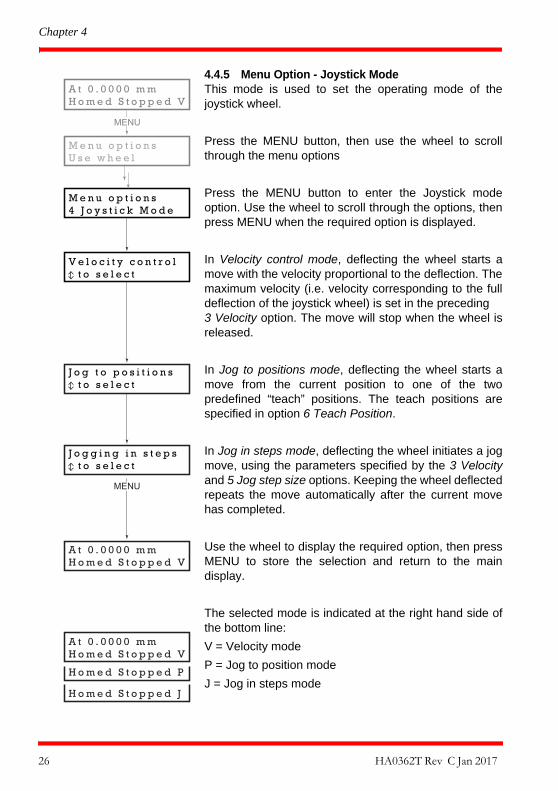
4.4.5 Menu Option - Joystick ModeThis mode is used to set the operating mode of thejoystick wheel.
Press the MENU button, then use the wheel to scrollthrough the menu options
Press the MENU button to enter the Joystick modeoption. Use the wheel to scroll through the options, thenpress MENU when the required option is displayed.
In Velocity control mode, deflecting the wheel starts amove with the velocity proportional to the deflection. Themaximum velocity (i.e. velocity corresponding to the fulldeflection of the joystick wheel) is set in the preceding 3 Velocity option. The move will stop when the wheel isreleased.
In Jog to positions mode, deflecting the wheel starts amove from the current position to one of the twopredefined “teach” positions. The teach positions arespecified in option 6 Teach Position.
In Jog in steps mode, deflecting the wheel initiates a jogmove, using the parameters specified by the 3 Velocityand 5 Jog step size options. Keeping the wheel deflectedrepeats the move automatically after the current movehas completed.
Use the wheel to display the required option, then pressMENU to store the selection and return to the maindisplay.
The selected mode is indicated at the right hand side ofthe bottom line:
V = Velocity mode
P = Jog to position mode
J = Jog in steps mode
A t 0 . 0 0 0 0 m mH o m e d S t o p p e d V
M e n u o p t i o n sU s e w h e e l
M e n u o p t i o n s4 J o y s t i c k M o d e
V e l o c i t y c o n t r o l t o s e l e c t
MENU
J o g t o p o s i t i o n s t o s e l e c t
J o g g i n g i n s t e p s t o s e l e c t
A t 0 . 0 0 0 0 m mH o m e d S t o p p e d V
A t 0 . 0 0 0 0 m mH o m e d S t o p p e d V
H o m e d S t o p p e d P
H o m e d S t o p p e d J
MENU
26 HA0362T Rev C Jan 2017
K-Cube Stepper Motor Controller
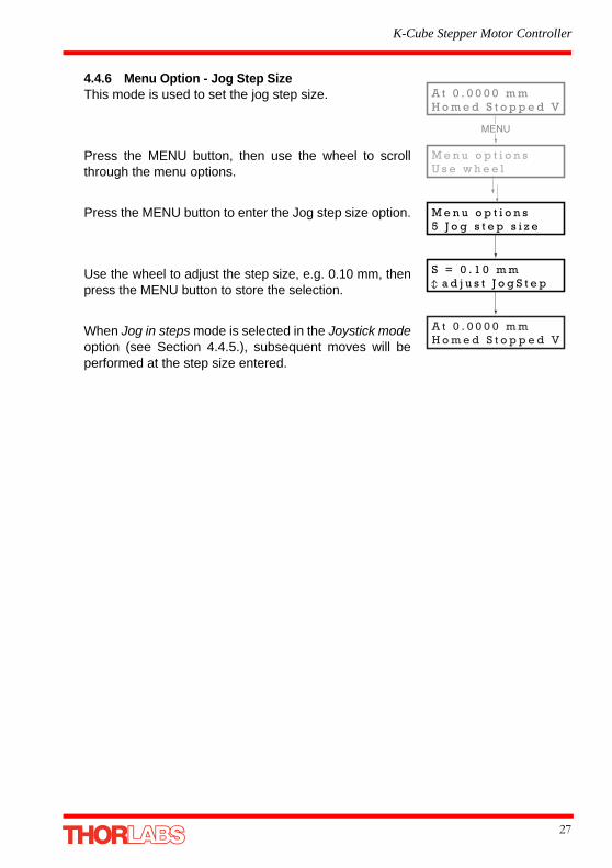
4.4.6 Menu Option - Jog Step SizeThis mode is used to set the jog step size.
Press the MENU button, then use the wheel to scrollthrough the menu options.
Press the MENU button to enter the Jog step size option.
Use the wheel to adjust the step size, e.g. 0.10 mm, thenpress the MENU button to store the selection.
When Jog in steps mode is selected in the Joystick modeoption (see Section 4.4.5.), subsequent moves will beperformed at the step size entered.
A t 0 . 0 0 0 0 m mH o m e d S t o p p e d V
M e n u o p t i o n sU s e w h e e l
M e n u o p t i o n s5 J o g s t e p s i z e
S = 0 . 1 0 m m a d j u s t J o g S t e p
MENU
A t 0 . 0 0 0 0 m mH o m e d S t o p p e d V
27

Chapter 4
4.4.7 Menu Option - Teach PositionThis mode is used to set the teach positions, used when the Joystick mode option isset to Jog to positions mode - see Section 4.4.5.
To set Teach Position 1...
Move the stage to the position to use as teach position 1.
Press the MENU button, then use the wheel to scrollthrough the menu options.
Press the MENU button to enter the Teach positionoption.
Use the wheel to select P1, then press the MENU buttonto store the current position as teach position 1 and returnto the main display.
To set Teach Position 2...
Move the stage to the position to use as teach position 2.
Press the MENU button, then use the wheel to scrollthrough the menu options.
Press the MENU button to enter the Teach positionoption.
Use the wheel to select P2, then press the MENU buttonto store the current position as teach position 2 and returnto the main display.
When Jog to position mode is selected in the Joystickmode option (see Section 4.4.5.), a downwardsdeflection of the wheel moves the stage to position 1, andan upwards deflection moves to position 2.
A t 1 0 . 0 0 0 0 m mH o m e d S t o p p e d V
M e n u o p t i o n sU s e w h e e l
M e n u o p t i o n s6 T e a c h p o s i t i o n
P 1 = 1 0 . 0 0 0 0 m m n u m s t o r e
MENU
A t 1 0 . 0 0 0 0 m mH o m e d S t o p p e d V
A t 5 . 0 0 0 0 m mH o m e d S t o p p e d V
A t 5 . 0 0 0 0 m mH o m e d S t o p p e d V
M e n u o p t i o n sU s e w h e e l
M e n u o p t i o n s6 T e a c h p o s i t i o n
P 2 = 5 . 0 0 0 0 m m n u m s t o r e
MENU
28 HA0362T Rev C Jan 2017
K-Cube Stepper Motor Controller
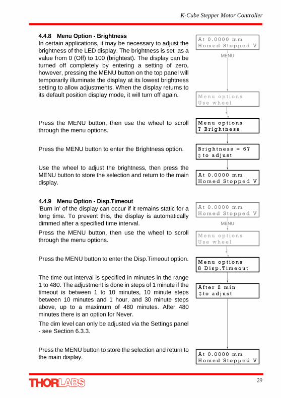
4.4.8 Menu Option - BrightnessIn certain applications, it may be necessary to adjust thebrightness of the LED display. The brightness is set as avalue from 0 (Off) to 100 (brightest). The display can beturned off completely by entering a setting of zero,however, pressing the MENU button on the top panel willtemporarily illuminate the display at its lowest brightnesssetting to allow adjustments. When the display returns toits default position display mode, it will turn off again.
Press the MENU button, then use the wheel to scrollthrough the menu options.
Press the MENU button to enter the Brightness option.
Use the wheel to adjust the brightness, then press theMENU button to store the selection and return to the maindisplay.
4.4.9 Menu Option - Disp.Timeout'Burn In' of the display can occur if it remains static for along time. To prevent this, the display is automaticallydimmed after a specified time interval.
Press the MENU button, then use the wheel to scrollthrough the menu options.
Press the MENU button to enter the Disp.Timeout option.
The time out interval is specified in minutes in the range1 to 480. The adjustment is done in steps of 1 minute if thetimeout is between 1 to 10 minutes, 10 minute stepsbetween 10 minutes and 1 hour, and 30 minute stepsabove, up to a maximum of 480 minutes. After 480minutes there is an option for Never.
The dim level can only be adjusted via the Settings panel- see Section 6.3.3.
Press the MENU button to store the selection and return tothe main display.
A t 0 . 0 0 0 0 m mH o m e d S t o p p e d V
M e n u o p t i o n sU s e w h e e l
M e n u o p t i o n s7 B r i g h t n e s s
B r i g h t n e s s = 6 7 t o a d j u s t
MENU
A t 0 . 0 0 0 0 m mH o m e d S t o p p e d V
A t 0 . 0 0 0 0 m mH o m e d S t o p p e d V
M e n u o p t i o n sU s e w h e e l
M e n u o p t i o n s8 D i s p . T i m e o u t
MENU
A t 0 . 0 0 0 0 m mH o m e d S t o p p e d V
A f t e r 2 m i n t o a d j u s t
29

Chapter 4
4.4.10 Menu Option - DisableIn certain applications, it may be advantageous to disable the wheel to remove thepossibility of unwanted motion due to accidental movement of the wheel.
Press the MENU button, then use the wheel to scrollthrough the menu options.
Press the MENU button to enter the Disable option.
Press the MENU button to store the selection and return tothe main display.
A t 0 . 0 0 0 0 m mH o m e d S t o p p e d V
M e n u o p t i o n sU s e w h e e l
M e n u o p t i o n s9 D i s a b l e
MENU
A t 0 . 0 0 0 0 m mH o m e d S t o p p e d V
30 HA0362T Rev C Jan 2017

K-Cube Stepper Motor Controller
4.4.11 Menu Option - Select stage
To ensure that a particular stage is driven properly by the system, a number ofparameters must first be set. These parameters relate to the physical characteristicsof the stage being driven (e.g. min and max positions, leadscrew pitch, homingdirection etc.).
Older version devices must be associated manually using the top panel menu. Oncethis association has been made, the APT server applies automatically, suitabledefault parameter values on boot up of the software.
Press the MENU button, then use the wheel to scrollthrough the menu options.
Press the MENU button to enter the Select stage option.
Use the wheel to scroll through the options to the requiredstage type. The stage types supported are:
NR360S, FW103, DRV013, DRV014, PLS2, PLS3,ZFS25, ZFS13, ZFS06, ZST225, ZST213, ZST206,ZST25, ZST13, ZST6
Press the MENU button to store the selection and return tothe main display.
Note
Later version actuators and stages have an identification eprom fitted such that the system will recognise automatically the actuator type and install
suitable defaults at start up. In this case, the start up screens will show ‘Stage connected xxx’ as shown in Fig. 3.4 and this menu option is not visible.
If this menu option is visible then the stage/actuator connected is not fitted with an eprom and the stage association must be performed manually as
detailed below.
A t 0 . 0 0 0 0 m mH o m e d S t o p p e d V
M e n u o p t i o n sU s e w h e e l
M e n u o p t i o n s1 0 S e l e c t s t a g e
S e l e c t s t a g eD R V 0 1 4
MENU
A t 0 . 0 0 0 0 m mS t o p p e d V
31

Chapter 5 PC Operation - Tutorial
5.1 Introduction
The following brief tutorial guides the user through a typical series of moves andparameter adjustments performed using the PC based APT software. It assumes thatthe unit is electrically connected as shown in Section 3.3., and that the APT Softwareis already installed - see Section 3.1. For illustration purposes, it also assumes that aZST motor is connected to the ‘Motor’ connector on the rear panel.
5.2 Using the APT User Utility
The APT User.exe application allows the user to interact with any number of APThardware control units connected to the PC USB Bus (or simulated via the APTConfigutility). This program allows multiple graphical instrument panels to be displayed sothat multiple APT units can be controlled. All basic operating parameters can be setthrough this program, and all basic operations (such as motor moves) can be initiated.Hardware configurations and parameter settings can be saved, which simplifiessystem set up whenever APT User is run up.
Fig. 5.1 Typical APT User Screen
1) If required, perform the stage association as detailed in Section 4.4.11.
2) Run the APT User program - Start/Programs/Thorlabs/APT/APT User.
32

K-Cube Stepper Motor Controller
3) The actuator type recognised/associated is displayed in the ‘Settings’ window.See Section 5.11. and Section 6.3. for further details on the parameter valuesshown in the ‘Settings’ display.
Fig. 5.2 Stepper Driver K-Cube Software GUI
The APT User utility will be used throughout the rest of this tutorial to interface withthe Stepper Driver K-Cube.
33

Chapter 5
5.3 Homing Motors
Homing the motor moves the actuator to the home limit switch and resets the internalposition counter to zero. The limit switch provides a fixed datum that can be foundafter the system has been powered up.
Fig. 5.3 Stepper Driver K-Cube GUI
1) Click the ‘Home’ button. Notice that the led in the button lights to indicate thathoming is in progress and the displayed position counts down to 000.000, i.e thehome position.
2) When homing is complete, the ‘Homed’ LED is lit as shown above.
See Appendix E , Section E.2.2. for background information on the home position.
Note
Homing can also be performed by holding down both front panel buttons for around 2 seconds.
34 HA0362T Rev C Jan 2017

K-Cube Stepper Motor Controller
5.4 Moving to an Absolute Position
Absolute moves are measured in real world units (e.g. millimetres), relative to theHome position.
1) Click the position display.
Fig. 5.4 Absolute Position Popup Window
2) Enter 0.3589 into the pop up window
3) Click ‘OK’. Notice that the position display counts up to 0.35900 to indicate a moveto the absolute position entered.
35

Chapter 5
5.5 Changing Motor Parameters
Moves are performed using a trapezoidal velocity profile (see Appendix E , SectionE.1.3.). The velocity settings relate to the maximum velocities at which a move isperformed, and the acceleration at which the motor speeds up from zero to maximumvelocity.
1) On the GUI panel, click the ‘Settings’ button (bottom right hand corner of thedisplay) to show the Settings panel.
Fig. 5.5 Settings Panel - Move/Jogs Tab
2) Select the Move/Jogs tab as shown in Fig. 5.5.
3) In the ‘Moves’ field, enter parameter values as follows:‘Max. Vel’ - ‘4’‘Accn/Dec’ - ‘1.5’
4) Click ‘OK’ to save the settings and close the window.
5) Any further moves initiated will now be performed at a maximum velocity of 4.0mm per second, with an acceleration of 1.5 mm/sec/sec.
Note
In current versions of software, the ‘Min Vel’ parameter is locked at zero and cannot be adjusted.
36 HA0362T Rev C Jan 2017

K-Cube Stepper Motor Controller
5.6 Jogging
During PC operation, the motor actuators are jogged using the GUI panel arrow keys.There are two jogging modes available, ‘Single Step’ and ‘Continuous’. In ‘SingleStep’ mode, the motor moves by the step size specified in the Step Distanceparameter. If the jog key is held down, single step jogging is repeated until the buttonis released - see Fig. 6.3. In ‘Continuous’ mode, the motor actuator will accelerate andmove at the jog velocity while the button is held down.
1) On the GUI panel, click the ‘Settings’ button to display the Settings panel.
Fig. 5.6 Settings Panel - Move/Jogs Tab
2) Select the Move/Jogs tab as shown in Fig. 5.6.
3) In the ‘Jogs’ field, enter parameter values as follows:Velocity Profile‘Max. Vel’ - ‘1’‘Accn/Dec’ - ‘0.5’
Operating Modes‘Jogging’ - ‘Single Step’‘Stopping’ - ‘Profiled’‘Step Distance’ - ‘0.5’
4) Click ‘OK’ to save the settings and close the window.
5) Click the Jog Arrows on the GUI panel to jog the motor. Notice that the positiondisplay increments 0.5 every time the button is clicked.
Note
In current versions of software, the ‘Min Vel’ parameter is locked at zero and cannot be adjusted.
37

Chapter 5
5.7 Stopping the Stage
The drive channel is enabled and disabled by clicking the ‘Enable’ button on the GUIpanel. The green indicator in the button center is lit when the drive channel is enabled.Disabling the channel removes the drive power.
During operation, the stage can be stopped at any time by clicking the ‘Stop’ buttonon the GUI panel. Using this button does not remove power to the drive channel.
.
Fig. 5.7 APT GUI User Screen
38 HA0362T Rev C Jan 2017

K-Cube Stepper Motor Controller
5.8 Graphical Control Of Motor Positions (Point and Move)
The GUI panel display can be changed to a graphical display, showing the position ofthe motor channel(s). Moves to absolute positions can then be initiated by positioningthe mouse within the display and clicking.
To change the panel view to graphical view, right click in the screen and select‘Graphical View’.
Fig. 5.8 Stepper Driver K-Cube GUI Panel - Graphical View
Consider the display shown above for an Stepper Driver K-Cube .
The right hand display shows the channel and motor unit parameters; i.e. controllerunit type and serial number, associated stage and actuator type, minimum andmaximum positions, current position, units per grid division and cursor position. Allunits are displayed in real world units, either millimetres or degrees.
The left hand display shows a circle, which represents the current position of themotor associated with the specified controller (absolute position data is displayed inthe 'Chan Pos' field).
The vertical divisions relate to the travel of the stage/actuator associated with theStepper Driver K-Cube (the stage/actuator is selected in the ‘APT Config’ utility). Forexample, the screen shot above shows the parameters for a 25mm travel ZFS25(B)motor actuator. The graph shows 10 divisions in the X axis, which relates to 2.5 mmof travel per division (25mm in total).
The graphical panel has two modes of operation, ‘Jog’ and ‘Move’, which are selectedby clicking the buttons at the bottom right of the screen.
Note
For single channel units such as the Stepper Driver K-Cube, the Channel 2 parameters are greyed out.
39

Chapter 5
Move Mode
When ‘Move’ is selected, the motors move to an absolute position which correspondsto the position of the cursor within the screen.
To specify a move:
1) Position the mouse within the window. For reference, the absolute motor positionvalues associated with the mouse position is displayed in the 'Cursor Positionfield.
2) Click the left hand mouse button to initiate the move.
Jog Mode
When ‘Jogging’ mode is selected, the motors are jogged each time the left mousebutton is clicked.
The Jog direction corresponds to the position of the cursor relative to the circle(current motor position), e.g. if the cursor is to the left of the circle the motor will jogleft. The Jog Step size is that selected in the Settings panel - see Section 6.3.
Stop
To stop the move at any time, click the ‘Stop’ button.
Returning to Panel View
To return to panel view, right click in the graphical panel and select ‘Panel View’.
40 HA0362T Rev C Jan 2017

K-Cube Stepper Motor Controller
5.9 Setting Move Sequences
This section explains how to set move sequences, allowing several positions to bevisited without user intervention.
For details on moving to absolute positions initiated by a mouse click – see Section5.8.
1) From the Motor GUI Panel, select 'Move Sequencer' tab to display the MoveSequencer window.
Fig. 5.9 Move Sequencer Window
2) Right click, in the move data field to display the pop up menu.
Fig. 5.10 Move Sequencer Pop Up Menu
41

Chapter 5
3) Select 'New' to display the 'Move Editor' panel.
Fig. 5.11 Move Editor Window
Move data is entered/displayed as follows:
Dist/Pos: - the distance to move from the current position (if 'Relative' is selected)
or the position to move to (if 'Absolute' is selected).
Dwell Time: - after the move is performed, the system can be set to wait for aspecified time before performing the next move in the sequence. The Dwell time is thetime to wait (in milliseconds).
Return - if checked, the system will move to the position specified in the Dist/Pos field,wait for the specified Dwell time, and then return to the original position.
4) Min Vel: Acc: and Max Vel: - the velocity profile parameters for the move.
The motor accelerates at the rate set in the Acc field up to the speed set in the MaxVel field. As the destination approaches, the motor decelerates again to ensure thatthere is no overshoot of the position.
Note
In current versions of software, the ‘Min Vel’ parameter is locked at zero and cannot be adjusted.
42 HA0362T Rev C Jan 2017

K-Cube Stepper Motor Controller
5) Enter the required move data into the Move Editor and click OK. The move datais displayed in the main window as shown below.
Fig. 5.12 Main Window with Move Data
6) Repeat step 4 as necessary to build a sequence of moves. Move data can becopied, deleted, cut/pasted and edited by right clicking the data line(s) andselecting the appropriate option in the pop up menu (shown below).
Fig. 5.13 Pop Up Options
7) To run a single line of data, right click the appropriate data and select 'Run' fromthe pop up menu (shown above).
8) To run the entire sequence, click the 'Run' button (shown below). A Home movecan also be performed from this panel by clicking the ‘Home’ button.
Fig. 5.14 Home and Run Buttons
9) To save data to a file, or load data from a previously saved file, click the ‘Save’ or‘Load’ button and browse to the required location.
43

Chapter 5
5.10 Creating a Simulated Configuration Using APT Config
The 'APT Config' utility can be used to set up simulated hardware configurations andplace the APT Server into simulator mode. In this way it is possible to create anynumber and type of simulated (virtual) hardware units in order to emulate a set of realhardware. This is a particularly useful feature, designed as an aid learning how to usethe APT software and as an aid to developing custom software applications ‘offline’.
Any number of 'virtual' control units can be combined to emulate a colection ofphysical hardware units For example, an application program can be written, thentested and debugged remotely, before running with the hardware.
To create a simulated configuration proceed as follows:
1) Run the APT Config utility - Start/All Programs/Thorlabs/APT/APT Config.
2) Click the 'Simulator Configuration' tab.
Fig. 5.15 APT Configuration Utility - Simulator Configuration Tab
3) Enter ‘LAB1’ in the Configuration Names field.
44 HA0362T Rev C Jan 2017
K-Cube Stepper Motor Controller
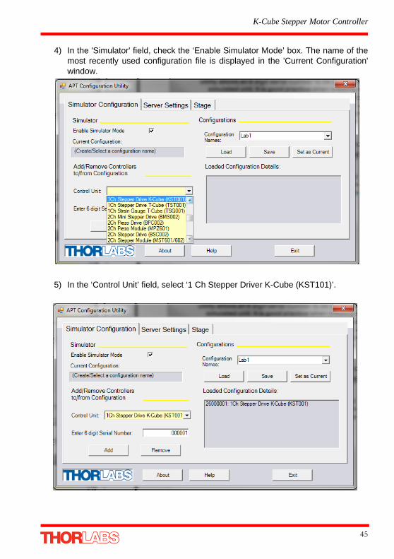
4) In the 'Simulator' field, check the ‘Enable Simulator Mode’ box. The name of themost recently used configuration file is displayed in the 'Current Configuration'window.
5) In the ‘Control Unit’ field, select ‘1 Ch Stepper Driver K-Cube (KST101)’.
45

Chapter 5
6) In the ‘Enter 6 digit serial number’ field, enter the serial number of your stepperdrive unit.
7) Click the 'Add' button.
8) Repeat items (1) to (7) as required. (A unit can be removed from the configurationby selecting it in the 'Loaded Configuration Details' window and clicking the'Remove' button or by right clicking it and selecting the 'Remove' option from thepop up window).
9) Click 'Save'.
10)Click 'Set As Current' to use the configuration.
Note
Each physical APT hardware unit is factory programmed with a unique 8 digit serial number. In order to simulate a set of ‘real’ hardware the Config
utility allows an 8 digit serial number to be associated with each simulated unit. It is good practice when creating simulated
configurations for software development purposes to use the same serial numbers as any real hardware units that will be used. Although serial numbers are 8 digits (as displayed in the ‘Load Configuration Details’
window), the first two digits are added automatically and identify the type of control unit.
The prefixed digits relating to the Stepper Driver K-Cube are:
26xxxxxx - 1 Ch Stepper Drive K-Cube
46 HA0362T Rev C Jan 2017
K-Cube Stepper Motor Controller
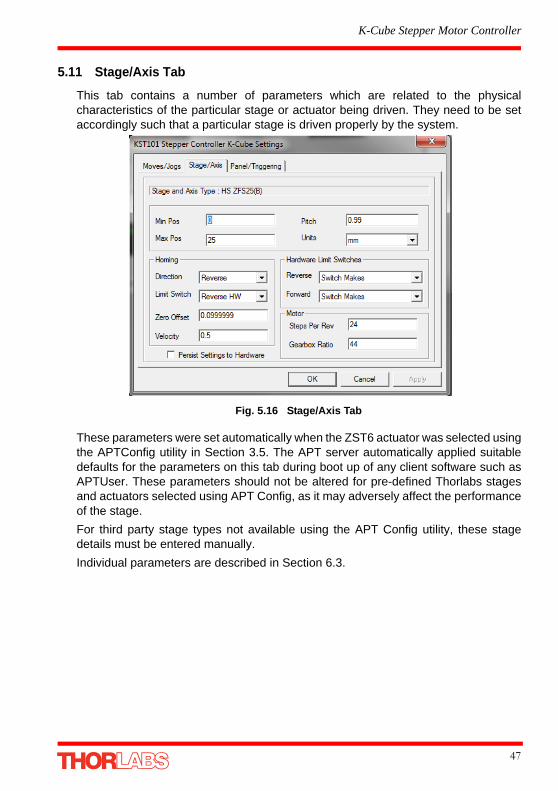
5.11 Stage/Axis Tab
This tab contains a number of parameters which are related to the physicalcharacteristics of the particular stage or actuator being driven. They need to be setaccordingly such that a particular stage is driven properly by the system.
Fig. 5.16 Stage/Axis Tab
These parameters were set automatically when the ZST6 actuator was selected usingthe APTConfig utility in Section 3.5. The APT server automatically applied suitabledefaults for the parameters on this tab during boot up of any client software such asAPTUser. These parameters should not be altered for pre-defined Thorlabs stagesand actuators selected using APT Config, as it may adversely affect the performanceof the stage.
For third party stage types not available using the APT Config utility, these stagedetails must be entered manually.
Individual parameters are described in Section 6.3.
47

Chapter 6 Software Reference
6.1 Introduction
This chapter gives an explanation of the parameters and settings accessed from theAPT software running on a PC. For information on the methods and properties whichcan be called via a programming interface, see Appendix D .
6.2 GUI Panel
The following screen shot shows the graphical user interface (GUI) displayed whenaccessing the Stepper Driver K-Cube using the APTUser utility.
Fig. 6.1 Stepper Driver K-Cube Software GUI
Jog - used to increment or decrement the motor position. When the button is clicked,the motor is driven in the selected direction at the jog velocity one step per click. Thestep size and jog velocity parameters are set in the 'Settings' panel (see Section 6.3.).
Note
The serial number of the Stepper Driver K-Cube associated with the GUI panel, the APT server version number, and the version number (in
brackets) of the embedded software running on the unit, are displayed in the top right hand corner. This information should always be provided
when requesting customer support.
48
K-Cube Stepper Motor Controller
Travel - displays the range of travel (in millimeters or degrees) of the motor.
Moving - lit when the motor is in motion.
Enable - applies power to the motor. With the motor enabled, the LED in the buttonis lit. Digital display - shows the position (in millimetres or degrees) of the motor. Themotor must be 'Homed' before the display will show a meaningful value, (i.e. thedisplayed position is relative to a physical datum, the limit switch).
Home - sends the motor to its 'Home' position - see Appendix E Section E.2.2. TheLED in the button is lit while the motor is homing.
Homed - lit when the motor has previously been 'Homed' (since power up).
Stop - halts the movement of the motor.
Limit switches - the LEDs are lit when the associated limit switch has been activated- see Appendix E Section E.2.3. for further details on limit switches.
Settings display - shows the following user specified settings:
Driver - the type of control unit associated with the specified channel.
Stage - the stage type and axis associated with the specified channel.
Note. By default, the software associates a ZST6 type actuator, unless the user hasused the APTConfig utility to associate a particular stage.
Calib File - the calibration file associated with the specified channel.
See the APTConfig utility helpfile for more details on assigning and using calibrationfiles.
Min/Max V - the minimum velocity at which a move is initiated, and the maximumvelocity at which the move is performed. Values are displayed in real world units (mm/s or degrees/s), and can be set via the 'Settings' panel (see Section 6.3.).
Accn - the rate at which the velocity climbs to, and slows from, maximum velocity,displayed in real world units (mm/s/s or degrees/s/s). The acceleration can be set viathe 'Settings' panel (see Section 6.3.) and is used in conjunction with the Min/Maxvelocity settings to determine the velocity profile of a motor move. See Appendix E
Section E.1.3. for more information on velocity profiles.
Jog Step Size - the size of step (in mm or degrees) taken when the jog signal isinitiated. The step size can be set either via the Settings panel or by calling theSetJogStepSize method.
Settings button - Displays the 'Settings' panel, which allows the operatingparameters to be entered for the motor drive - see Section 6.3.
Ident - when this button is pressed, the Channel LED on the front panel of theassociated hardware unit will flash for a short period.
Active - lit when the unit is operating normally and no error condition exists.
Error - lit when a fault condition occurs.
49
Chapter 6
6.3 Settings Panel
When the 'Settings' button on the GUI panel is clicked, the 'Settings' window isdisplayed. This panel allows motor operation parameters such as move/jog velocities,and stage/axis information to be modified. Note that all of these parameters haveprogrammable equivalents accessible through the ActiveX methods and propertieson this Control (refer to the Programming Guide in the APTServer helpfile for furtherdetails and to Section 2.3.4. for an overview of the APT ActiveX controls).
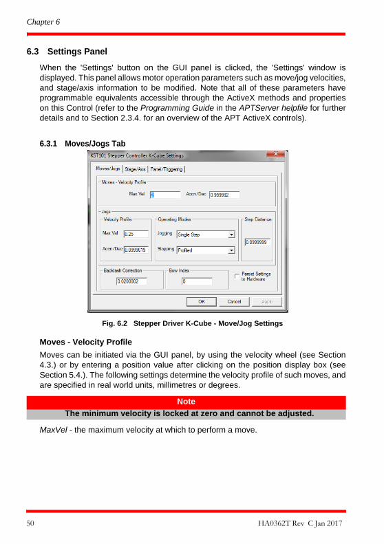
6.3.1 Moves/Jogs Tab
Fig. 6.2 Stepper Driver K-Cube - Move/Jog Settings
Moves - Velocity Profile
Moves can be initiated via the GUI panel, by using the velocity wheel (see Section4.3.) or by entering a position value after clicking on the position display box (seeSection 5.4.). The following settings determine the velocity profile of such moves, andare specified in real world units, millimetres or degrees.
MaxVel - the maximum velocity at which to perform a move.
Note
The minimum velocity is locked at zero and cannot be adjusted.
50 HA0362T Rev C Jan 2017

K-Cube Stepper Motor Controller
Accn/Dec - the rate at which the velocity climbs from zero to maximum, and slowsfrom maximum to zero.
Jogs
Jogs are initiated by using the ‘Jog’ keys on the GUI panel (see Section 5.6.), or theJog Buttons on the front panel of the unit.
Velocity Profile (specified in real world units, millimetres or degrees)
MaxVel - the maximum velocity at which to perform a jog
Accn/Dec - the rate at which the velocity climbs from minimum to maximum, andslows from maximum to minimum.
Operating Modes
Jogging - The way in which the motor moves when a jog command is received (i.e.front panel button pressed or GUI panel button clicked).
There are two jogging modes available, ‘Single Step’ and ‘Continuous’. In ‘SingleStep’ mode, the motor moves by the step size specified in the Step Distanceparameter. If the jog key is held down, single step jogging is repeated until the buttonis released - see Fig. 6.3. In ‘Continuous’ mode, the motor actuator will accelerate andmove at the jog velocity while the button is held down..
Fig. 6.3 Jog Modes
Single Step - the motor moves by the step size specified in the Step Distanceparameter.
Note
Under certain velocity parameter and move distance conditions, the maximum velocity may never be reached (i.e. the move comprises an
acceleration and deceleration phase only).
51

Chapter 6
Continuous - the motor continues to move until the jog signal is removed (i.e. jogbutton is released).
Stopping - the way in which the jog motion stops when the demand is removed.
Immediate - the motor stops quickly, in a non-profiled manner
Profiled - the motor stops in a profiled manner using the jog Velocity Profileparameters set above.
Step Distance - The distance to move when a jog command is initiated. The step sizeis specified in real world units (mm or degrees dependent upon the stage).
Backlash Correction - The system compensates for lead screw backlash duringreverse direction moves, by moving passed the demanded position by a specifiedamount, and then reversing. This ensures that positions are always approached in aforward direction. The Backlash Correction Distance is specified in real world units(millimeters or degrees). To remove backlash correction, this value should be set tozero.
Position Profiling
To prevent the motor from stalling, it must be ramped up gradually to its maximumvelocity. Certain limits to velocity and acceleration result from the torque and speedlimits of the motor, and the inertia and friction of the parts it drives.
The system incorporates a trajectory generator, which performs calculations todetermine the instantaneous position, velocity and acceleration of each axis at anygiven moment. During a motion profile, these values will change continuously. Oncethe move is complete, these parameters will then remain unchanged until the nextmove begins.
The specific move profile created by the system depends on several factors, such asthe profile mode and profile parameters presently selected, and other conditions suchas whether a motion stop has been requested.
Bow Index – This field is used to set the profile mode to either Trapezoidal or S-curve.A Bow Index of ‘0’ selects a trapezoidal profile. An index value of ‘1’ to ‘18’ selects anS-curve profile. In either case, the velocity and acceleration of the profile are specifiedusing the Velocity Profile parameters on the Moves/Jogs tab.
The Trapezoidal profile is a standard, symmetrical acceleration/deceleration motioncurve, in which the start velocity is always zero. This profile is selected when the BowIndex field is set to ‘0’.
In a typical trapezoidal velocity profile, (see Fig. 6.4.), the stage is ramped atacceleration ‘a’ to a maximum velocity ‘v’. As the destination is approached, the stage
52 HA0362T Rev C Jan 2017

K-Cube Stepper Motor Controller
is decelerated at ‘a’ so that the final position is approached slowly in a controlledmanner.
Fig. 6.4 Graph of a trapezoidal velocity profile
The S-curve profile is a trapezoidal curve with an additional 'Bow Value' parameter,which limits the rate of change of acceleration and smooths out the contours of themotion profile. The Bow Value is applied in mm/s3 and is derived from the Bow Indexfield as follows:
Bow Value = 2 (Bow Index -1) within the range 1 to 262144 (Bow Index 1 to 18).
In this profile mode, the acceleration increases gradually from 0 to the specifiedacceleration value, then decreases at the same rate until it reaches 0 again at thespecified velocity. The same sequence in reverse brings the axis to a stop at theprogrammed destination position.
Example
Fig. 6.5 Typical S-Curve Profile
The figure above shows a typical S-curve profile. In segment (1), the S-curve profiledrives the axis at the specified Bow Index (BI) until the maximum acceleration (A) isreached. The axis continues to accelerate linearly (Bow Index = 0) through segment(2). The profile then applies the negative value of Bow Index to reduce theacceleration to 0 during segment (3). The axis is now at the maximum velocity (V), atwhich it continues through segment (4). The profile then decelerates in a similar
velocity
maximum velocity (v)
time
acceleration (slope) a
BI BI
A D
-BI -BI
V
Velo
city
1 2 3 4 5 6 7
A - accelerationD - decelerationV - velocityBI - bow index
53

Chapter 6
manner to the acceleration phase, using the Bow Index to reach the maximumdeceleration (D) and then bring the axis to a stop at the destination.
Persist Settings to Hardware - Many of the parameters that can be set for theStepper Driver K-Cube can be stored (persisted) within the unit itself, such that whenthe unit is next powered up these settings are applied automatically. This isparticularly important when the driver is being used manually in the absence of a PCand USB link. The Velocity Profile and Jogging parameters described previously aregood examples of settings that can be altered and then persisted in the driver for usein absence of a PC. To save the settings to hardware, check the ‘Persist Settings toHardware’ checkbox before clicking the ‘OK button.
Note
The higher the Bow Index, then the shorter the BI phases of the curve, and the steeper the acceleration and deceleration phases. High values of Bow
Index may cause a move to overshoot or may result in instability.
Caution
The ‘Persist Settings’ functionality is provided to simplify use of the unit in the absence of a PC. When the unit is connected to a PC and is
operated via APTUser, the default APTServer settings will be loaded at boot up, even if the ‘Persist Settings’ option has been checked.
54 HA0362T Rev C Jan 2017

K-Cube Stepper Motor Controller
6.3.2 Stage/Axis Tab
Fig. 6.6 Stepper Driver K-Cube - Stage/Axis Settings
Stage and Axis Type - For Thorlabs stages, the stage type is displayed automaticallyonce the axis has been associated using the APTConfig utility. For third party stages,the display shows ‘Unknown’.
Note
This tab contains a number of parameters which are related to the physical characteristics of the particular stage being driven. They need to be set
accordingly such that a particular stage is driven properly by the system.
For Thorlabs stages, the APT Config utility can be used to associate a specific stage and axis type with the motor channel (refer to the APT Config helpfile
for further details on how to associate a stage and axis). Once this association has been made, the APT server will automatically apply suitable defaults for the parameters on this tab during boot up of the software. These parameters
should not be altered for pre-defined Thorlabs stages selected using APT Config, as it may adversely affect the performance of the stage.
For custom stage types not available using the APT Config utility, the stage details must be entered manually. Individual parameters are described in the
following paragraphs.
Caution
Extreme care must be taken when modifying the stage related settings that follow. Some settings are self consistent with respect to each other, and illegal
combinations of settings can result in incorrect operation of the physical motor/stage combination being driven. Consult Thorlabs for advice on settings
for stage/actuator types that are not selectable via the APTConfig utility.
55

Chapter 6
Min Pos - the stage/actuator minimum position (typically zero).
Max Pos - the stage/actuator maximum position.
Pitch - the pitch of the motor lead screw (i.e. the distance travelled (in mm or degrees)per revolution of the leadscrew).
Units - the ‘real world’ positioning units (mm or degrees).
Homing
When homing, a stage typically moves in the reverse direction, (i.e. towards thereverse limit switch). The following settings allow support for stages with both Forwardand Reverse limits.
Direction - the direction sense to move when homing, either Forward or Reverse.
Limit Switch - The hardware limit switch associated with the home position, eitherForward HW or Reverse HW.
Zero Offset - the distance offset (in mm or degrees) from the limit switch to the Homeposition.
Velocity - the maximum velocity at which the motors move when Homing.
For further information on the home position, see Section E.2.2.
Hardware Limit Switches
The operation of the limit switches is inherent in the design of the associated stage oractuator. The following parameters notify the system to the action of the switcheswhen contact is made. Select Rev Switch or Fwd Switch as required, then select therelevant operation.
Switch Makes - The switch closes on contactSwitch Breaks - The switch opens on contactIgnore/Absent - The switch is missing, or should be ignored.
Note
Typically, the following two parameters are set the same, i.e. both Forward or both Reverse.
Caution
The homing velocity should not be increased above the 250 µm/s factory setting as this may damage the limit switches.
Note
The minimum velocity and acceleration/deceleration parameters for a home move are taken from the existing move velocity profile parameters.
56 HA0362T Rev C Jan 2017

K-Cube Stepper Motor Controller
Motor
These parameters are used to set the 'resolution' characteristics of the stepper motorconnected to the selected channel. The resolution of the motor, combined with othercharacteristics (such as lead screw pitch) of the associated actuator or stage,determines the overall resolution.
Steps Per Rev - The number of full steps per revolution of the stepper motor(minimum '1', maximum '10000').
Gearbox Ratio - The ratio of the gearbox. For example, if the gearbox has a reductionratio of X:1 (i.e. every 1 turn at the output of the gearbox requires X turns of the motorshaft) then the Gearbox Ratio value is set to X. (minimum '1', maximum '1000').
Persist Settings to Hardware - Many of the parameters that can be set for theStepper Driver K-Cube can be stored (persisted) within the unit itself, such that whenthe unit is next powered up these settings are applied automatically. This isparticularly important when the driver is being used manually in the absence of a PCand USB link. The homing parameters and limit switch settings described previouslyare good examples of settings that can be altered and then persisted in the driver for
Note
The Gearbox Ratio parameter is applicable only to motors fitted with a gearbox.
Note
The ‘Steps Per Rev’ and ‘Gearbox Ratio’ parameters, together with the ‘Pitch’ and ‘Units’ parameters are used to calculate the calibration factor
for use when converting real world units to microsteps. However, the ‘Steps Per Rev’ parameter is entered as full steps, not microsteps. The system automatically applies a factor of 2048 microsteps per full step.
The majority of Thorlabs stepper motor actuators have 200 full steps per rev and no gearbox fitted. For these motors the Steps Per Rev and
Gearbox Ratio parameters have values of 200 and 1 respectively. As an exception to this, the ZST family of actuators use 24 steps per rev stepper motors fitted with a 41:1 reduction gearbox. In this case, the Steps Per Rev and Gearbox Ratio should be set to '24' and '41' respectively. The
equivalent calibration constant is then calculated as:
24 x 2048 x 41 = 2,015,232
24 steps per revolution2048 microsteps per full step
41:1 reduction gearbox1.0 mm lead screw pitch
57
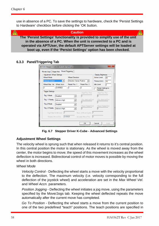
Chapter 6
use in absence of a PC. To save the settings to hardware, check the ‘Persist Settingsto Hardware’ checkbox before clicking the ‘OK button.
6.3.3 Panel/Triggering Tab
Fig. 6.7 Stepper Driver K-Cube - Advanced Settings
Adjustment Wheel Settings
The velocity wheel is sprung such that when released it returns to it’s central position.In this central position the motor is stationary. As the wheel is moved away from thecenter, the motor begins to move; the speed of this movement increases as the wheeldeflection is increased. Bidirectional control of motor moves is possible by moving thewheel in both directions.
Wheel Mode
Velocity Control - Deflecting the wheel starts a move with the velocity proportionalto the deflection. The maximum velocity (i.e. velocity corresponding to the fulldeflection of the joystick wheel) and acceleration are set in the Max Wheel Vel.and Wheel Accn. parameters.
Position Jogging - Deflecting the wheel initiates a jog move, using the parametersspecified by the Move/Jogs tab. Keeping the wheel deflected repeats the moveautomatically after the current move has completed.
Go To Position - Deflecting the wheel starts a move from the current position toone of the two predefined “teach” positions. The teach positions are specified in
Caution
The ‘Persist Settings’ functionality is provided to simplify use of the unit in the absence of a PC. When the unit is connected to a PC and is
operated via APTUser, the default APTServer settings will be loaded at boot up, even if the ‘Persist Settings’ option has been checked.
58 HA0362T Rev C Jan 2017

K-Cube Stepper Motor Controller
the Preset Pos. 1 and Preset Pos. 2 parameters, and are measured in number ofsteps from the home position.
Wheel Direction
The direction of a move initiated by the velocity wheel is specified as follows:
Disabled - The wheel is disabled to remove any unwanted motion due toaccidental movement of the wheel.
Direction Sense Positive - Upwards rotation of the wheel results in a positivemotion (i.e. increased position count).
Note. The following option applies only when the Wheel Mode is set to VelocityControl. If set to Position Jogging or Go to Position Mode, the following option isignored.
Direction Sense Negative - Upwards rotation of the wheel results in a negativemotion (i.e. decreased position count).
Display Brightness
In certain applications, it may be necessary to adjust the brightness of the LED displayon the top of the unit. The brightness is set in the Active Level parameter, as a valuefrom 0 (Off) to 100 (brightest). The display can be turned off completely by entering asetting of zero, however, pressing the MENU button on the top panel will temporarilyilluminate the display at its lowest brightness setting to allow adjustments. When thedisplay returns to its default position display mode, it will turn off again.
Furthermore, 'Burn In' of the display can occur if it remains static for a long time. Toprevent this, the display is automatically dimmed after the time interval specified in theTimeout (min) parameter has elapsed. The time interval is specified in minutes in therange 0 (never dimmed) to 480. The dim level is set in the Idle Level parameter, as avalue from 0 (Off) to 10 (brightest) but is also limited by the Active Value parameter ifthis is lower.
Persist Settings to Hardware - Many of the parameters that can be set for the DCDriver K-Cube can be stored (persisted) within the unit itself, such that when the unitis next powered up these settings are applied automatically. This is particularlyimportant when the driver is being used manually in the absence of a PC and USBlink. The wheel, and trigger parameters described here are good examples of settingsthat can be altered and then persisted in the driver for use in absence of a PC. Tosave the settings to hardware, check the ‘Persist Settings to Hardware’ checkboxbefore clicking the ‘OK button.
Caution
The ‘Persist Settings’ functionality is provided to simplify use of the unit in the absence of a PC. When the unit is connected to a PC and is
operated via APTUser, the default APTServer settings will be loaded at boot up, even if the ‘Persist Settings’ option has been checked.
59

Chapter 6
Triggering Introduction
The K-Cube motor controllers have two bidirectional trigger ports (TRIG1 and TRIG2)that can be used to read an external logic signal or output a logic level to controlexternal equipment. Either of them can be independently configured as an input or anoutput and the active logic state can be selected High or Low to suit the requirementsof the application. Electrically the ports output 5 Volt logic signals and are designedto be driven from a 5 Volt logic.
When the port is used in the input mode, the logic levels are TTL compatible, i.e. avoltage level less than 0.8 Volt will be recognised as a logic LOW and a level greaterthan 2.4 Volt as a logic HIGH. The input contains a weak pull-up, so the state of the inputwith nothing connected will default to a logic HIGH. The weak pull-up feature allows apassive device, such as a mechanical switch to be connected directly to the input.
When the port is used as an output it provides a push-pull drive of 5 Volts, with themaximum current limited to approximately 8 mA. The current limit prevents damagewhen the output is accidentally shorted to ground or driven to the opposite logic stateby external circuity.
Warning: do not drive the TRIG ports from any voltage source that can produce anoutput in excess of the normal 0 to 5 Volt logic level range. In any case the voltage atthe TRIG ports must be limited to -0.25 to +5.25 Volts.
Input Trigger Modes
When configured as an input, the TRIG ports can be used as a general purpose digitalinput, or for triggering a relative, absolute or home move. When used for triggering amove, the port is edge sensitive. In other words, it has to see a transition from theinactive to the active logic state (Low->High or High->Low) for the trigger input to berecognized. For the same reason a sustained logic level will not trigger repeatedmoves. The trigger input has to return to its inactive state first in order to start the nexttrigger. The mode is set in the Trig 1 Mode and Trig 2 Mode parameters as follows:
Disabled - The trigger IO is disabled
Digital Input - General purpose logic input (read through status bits using theLLGetStatusBits method).
Trig In Rel. Move - Input trigger for relative move.
Trig In Abs. Move - Input trigger for absolute move.
Trig In Home - Input trigger for home move.
When the trigger mode is selected to Trig In Rel Move or Trig In Abs Move, the relativedistance or absolute position to move, can be entered in the Relative Move Dist andAbsolute Move Pos. parameters.
60 HA0362T Rev C Jan 2017
K-Cube Stepper Motor Controller
Output Trigger Modes
When the Trig 1 Mode and Trig 2 Mode parameters are configured as outputs, theTRIG ports can be used as a general purpose digital output, or to indicate motionstatus or to produce a trigger pulse at configurable positions as follows:
Digital Output - General purpose logic output (set using the LLSetGetDigOPsmethod).
Trig Out In Motion - Trigger output active (level) when motor 'in motion'. The outputtrigger goes high (5V) or low (0V) (as set in the Trig 1. Polarity and Trig. 2 Polarityparameters) when the stage is in motion.
Trig Out Max Vel - Trigger output active (level) when motor at 'max velocity'.
Trig Out Pos. Steps Fwd - Trigger output active (pulsed) at pre-defined positionsmoving forward. Only one Trigger port at a time can be set to this mode. SeeTrigger Out Position Steps for further details.
Trig Out Pos. Steps Rev - Trigger output active (pulsed) at pre-defined positionsmoving backwards. Only one Trigger port at a time can be set to this mode. SeeTrigger Out Position Steps for further details.
Trig Out Pos. Steps Both - Trigger output active (pulsed) at pre-defined positionsmoving forwards and backward. Only one Trigger port at a time can be set to thismode. See Trigger Out Position Steps for further details.
Trigger Out Position Steps
In the last three modes described above, the controller outputs a configurable numberof pulses (set in the Num. Pulses Fwd and Num. Pulses Rev parameters), ofconfigurable width (Trig Pulse Width), when the actual position of the stage matchesthe position values configured as the Start Position and Position Interval (Start Pos.Fwd and Start Pos. Rev. These modes allow external equipment to be triggered atexact position values.
Using the last three modes, position triggering can be configured to be unidirectional(Trig Out Pos. Steps Fwd or Trig Out Pos. Steps Rev) or bidirectional (Trig Out Pos.Steps Both). In bidirectional mode the forward and reverse pulse sequences can beconfigured separately. A cycle count setting (Num. of Move Cycles) allows the uni- orbidirectional position triggering sequence to be repeated a number of times.
Note
If the trigger mode is not set to one of the three position modes described previously, then the following parameters are not applicable and will be
greyed out.
61

Chapter 6
Fig. 6.8 Position Steps Triggering
Example for a move from 0 to 20 mm and back.
In forward direction: The first trigger pulse occurs at 10 mm (StartPosFwd), the nexttrigger pulse occurs after another 5 mm (PosIntervalFwd), the stage then moves to 20mm.
In reverse direction: The next trigger occurs when the stage gets to 12 mm.
Note that position triggering can only be used on one TRIG port at a time, as there isonly one set of position trigger parameters.
Triggering Polarity
The polarity of the trigger pulse is specified in the Trig. 1 Polarity and Trig 2 Polarity
parameters as follows:
Active is High - The active state of the trigger port is logic HIGH 5V (trigger inputand output on a rising edge).
Active is Low - The active state of the trigger port is logic LOW 0V (trigger inputand output on a falling edge).
Time
Time
Trig Voltage
Pos1 Fwd
Pos2 FwdPos1 Rev
10 mm
15 mm
12 mm
5V
0V
StartPosFwd
StartPosRev
PosIntervalFwd
62 HA0362T Rev C Jan 2017

K-Cube Stepper Motor Controller
6.3.4 Rotation StagesTab
Absolute Position Reporting Mode This setting relates to the way in which the angular position is displayed on the GUIpanel. There are two options:
Equivalent Angle 0 to 360 degrees – The maximum displayed position is 359.99°.If a stage is driven past the 360° rotation point, the display reverts back to zeroand counts up to 360° again.
Total Angle (360 x Num Revs + Angular Offset) – The total angular rotation isdisplayed, e.g. for a movement of two full rotations plus 10°, the display will show730°.
Note. The following parameters are applicable only if the Absolute PositionReporting Mode is set to ‘Equivalent Angle 0 to 360 degrees’.
Panel Display Rotation Move Mode This setting specifies the move direction. There are three options:
Rotate Positive – The move is performed in a positive direction
Rotate Negative - The move is performed in a negative direction
Rotate Quickest - The move is performed in the quickest direction
63

Appendix A Rear Panel Connector Pinout Details
A.1 Rear Panel Motor Control Connector
The ‘Motor’ connector provides connection to the stepper motor actuator. The pinfunctions are detailed in Fig. A.1.
Fig. A.1 MOTOR I/O Connector Pin Identification
Pin Description Pin Description
1 Ground 9 Stage Identification
2 CCW Limit Switch 10 +5V
3 CW Limit Switch 11 Enc A +ve
4 Phase B -ve 12 Enc A -ve
5 Phase B +ve 13 Enc B +ve
6 Phase A -ve 14 Enc B -ve
7 Phase A +ve 15 For Future Use
8 For Future Use
Caution
DO NOT connect a motor actuator while the K-Cube is powered up.
Only use motor drive cables supplied by Thorlabs, other cables may have incompatible wiring.
5
101115
61
64

Appendix B Preventive Maintenance
B.1 Safety Testing
PAT testing in accordance with local regulations, should be performed on a regularbasis, (typically annually for an instrument in daily use).
B.2 Cleaning
Note
The equipment contains no user servicable parts. Only personnel authorized by Thorlabs Ltd and trained in the maintenance of this
equipment should remove its covers or attempt any repairs or adjustments. Maintenance is limited to safety testing and cleaning as
described in the following sections.
Warning
Disconnect the power supply before cleaning the unit.
Never allow water to get inside the case.
Do not saturate the unit.
Do not use any type of abrasive pad, scouring powder or solvent, e.g. alcohol or benzene.
65

Appendix C Specifications
C.1 Specifications
Parameter Value
Motor Output
Motor Drive Voltage 12-15 V (Depending on Supply)
Motor Drive Current 750 m A (peak)
Motor Drive Type 12-bit PWM Control
Control Algorithm Open Loop Microstepping
High Resolution Stepping 2048 Microsteps per Full Step49,152 Microsteps per Revolution (24 Step Motor)(409600 Microsteps per Revolution (200 Step Motor)
Position Feedback Quadrature Encoder (QEP) Input, 5 V Differential
Encoder Feedback Bandwidth 500 kHz
Position Counter 32-bit
Operating Modes Position, Velocity
Velocity Profile Trapezoidal or ‘S’ Profile
Motor Drive Connector (15 Way D-Type)
Motor Drive Outputs Phase A & B
Quadrature Encoder (QEP) Input Differential
Limit Switch Inputs Forward, Reverse (+ Common Return)
Encoder Supply 5 V
Front Panel Controls
Sprung Potentiometer Wheel Bidirectional Velocity Control, Forward/Reverse Jogging or Position Presets
Input Power Requirements
Voltage 12 - 15V Regulated DC (15V recommended)
Current 1 A (peak)
General
Housing Dimensions (W x D x H)Excluding Buttons and Baseplate
60 x 60 x 47 mm (2.36" x 2.36" x 1.85)
Instrument Weight 140 g (5.0 oz)
66

K-Cube Stepper Motor Controller
Recommended Motor Requirements
Peak Powers 15 W
Step Angle Range 20° to 1.8°
Rated Phase Current up to 1 A Peak
Motor Mode Current
Coil Resistance (nominal) 5 to 20 ΩCoil Inductance (nominal) 2 to 5.5 mH
Phases 2
Position Control Open Loop
67

Appendix D Motor Control Method Summary
The 'Motor' ActiveX Control provides the functionality required for a client applicationto control one or more of the APT series of motor controller units.
To specify the particular controller being addressed, every unit is factory programmedwith a unique 8-digit serial number. This serial number is key to the operation of theAPT Server software and is used by the Server to enumerate and communicateindependently with multiple hardware units connected on the same USB bus. Theserial number must be specified using the HWSerialNum property before an ActiveXcontrol instance can communicate with the hardware unit. This can be done at designtime or at run time. Note that the appearance of the ActiveX Control GUI (graphicaluser interface) will change to the required format when the serial number has beenentered.
The Methods and Properties of the Motor ActiveX Control can be used to performactivities such as homing stages, absolute and relative moves, and changing velocityprofile settings. A brief summary of ech method and property is given below, for moredetailed information and individual parameter descriptiond please see the on-line helpfile supplied with the APT server.
Methods
DeleteParamSet Deletes stored settings for specific controller.
DisableHWChannel Disables the drive output.
DoEvents Allows client application to process other activity.
EnableHWChannel Enables the drive output.
GetAbsMovePos Gets the absolute move position.
GetAbsMovePos_AbsPos Gets the absolute move position (returned by value).
GetBLashDist Gets the backlash distance.
GetBLashDist_BLashDist Gets the backlash distance (returned by value).
GetCtrlStarted Gets the ActiveX Control started flag.
GetDispMode Gets the GUI display mode.
GetHomeParams Gets the homing sequence parameters.
GetHomeParams_HomeVel Gets the homing velocity parameter (returned byvalue).
GetHomeParams_ZeroOffset Gets the homing zero offset parameter (returned byvalue).
GetHWCommsOK Gets the hardware communications OK flag.
68
K-Cube Stepper Motor Controller
GetHWLimSwitches Gets the limit switch configuration settings.
GetJogMode Gets the jogging button operating modes.
GetJogMode_Mode Get the jogging button operating mode (returned byvalue).
GetJogMode_StopMode Gets the jogging button stopping mode (returned byvalue).
GetJogStepSize Gets the jogging step size.
GetJogStepSize_StepSize Gets the jogging step size (returned by value).
GetJogVelParams Gets the jogging velocity profile parameters.
GetJogVelParams_Accn Gets the jogging acceleration parameter (returnedby value).
GetJogVelParams_MaxVel Gets the jogging maximum velocity parameter(returned by value).
GetKCubePanelParams Gets the operating parameters of the velocity wheelon the top panel
GetKCubePosTriggerParams Gets operating parameters used when the triggeringmode is set to a trigger out position steps mode
GetKCubeTriggerParams Gets the operating parameters of the TRIG1 andTRIG2 connectors on the front panel.
GetMotorParams Gets the motor gearing parameters.
GetPhaseCurrents Gets the coil phase currents.
GetPosition Gets the current motor position.
GetPosition_Position Gets the current motor position (returned by value).
GetPositionEx Gets the current motor position.
GetPositionEx_UncalibPosition Gets the current uncalibrated motor position(returned by value).
GetPositionOffset Gets the motor position offset.
GetRelMoveDist Gets the relative move distance.
GetRelMoveDist_RelDist Gets the relative move distance (returned byreference).
GetStageAxis Gets the stage type information associated with themotor under control.
GetStageAxisInfo Gets the stage axis parameters.
GetStageAxisInfo_MaxPos Gets the stage maximum position (returned byvalue).
GetStageAxisInfo_MinPos Gets the stage minimum position (returned byvalue).
GetStatusBits_Bits Gets the controller status bits encoded in 32 bitinteger (returned by value).
69

Appendix D
GetVelParamLimits Gets the maximum velocity profile parameter limits.
GetVelParams Gets the velocity profile parameters.
GetVelParams_Accn Gets the move acceleration (returned by value).
GetVelParams_MaxVel Gets the move maximum velocity (returned byvalue).
Identify Identifies the controller by flashing unit LEDs.
LLGetStatusBits Gets the controller status bits encoded in 32 bitinteger.
LoadParamSet Loads stored settings for specific controller.
MoveAbsolute Initiates an absolute move.
MoveAbsoluteEnc Initiates an absolute move with specified positionsfor encoder equipped stages.
MoveAbsoluteEx Initiates an absoloute move with specified positions.
MoveAbsoluteRot Initiates an absolute move with specified positionsfor rotary stages.
MoveHome Initiates a homing sequence.
MoveJog Initiates a jog move.
MoveRelative Initiates a relative move.
MoveRelativeEnc Initiates a relative move with specified distances forencoder equipped stages.
MoveRelativeEx Initiates a relative move with specified distances.
MoveVelocity Initiates a move at constant velocity with no endpoint.
SaveParamSet Saves settings for a specific controller.
SetAbsMovePos Sets the absolute move position.
SetBLashDist Sets the backlash distance.
SetDispMode Sets the GUI display mode.
SetHomeParams Sets the homing sequence parameters.
SetHWLimSwitches Sets the limit switch configuration settings.
SetJogMode Sets the jogging button operating modes.
SetJogStepSize Sets the jogging step size.
SetJogVelParams Sets the jogging velocity profile parameters.
SetKCubePanelParams Sets the operating parameters of the velocity wheelon the top panel
SetKCubePosTriggerParams Sets operating parameters used when the triggeringmode is set to a trigger out position steps mode
SetKCubeTriggerParams Sets the operating parameters of the TRIG1 andTRIG2 connectors on the front panel of the unit.
70 HA0362T Rev C Jan 2017
K-Cube Stepper Motor Controller
SetMotorParams Sets the motor gearing parameters.
SetPhaseCurrents Sets the coil phase currents.
SetPositionOffset Sets the motor position offset.
SetPotParams Sets the velocity control potentiometer parameters(Cube drivers).
SetRelMoveDist Sets the relative move distance.
SetStageAxisInfo Sets the stage axis parameters.
SetVelParams Sets the velocity profile parameters.
ShowSettingsDlg Display the GUI Settings panel.
StartCtrl Starts the ActiveX Control (starts communicationwith controller)
StopCtrl Stops the ActiveX Control (stops communicationwith controller)
StopImmediate Stops a motor move immediately.
StopProfiled Stops a motor move in a profiled (decelleration)manner.
Properties
APTHelp Specifies the help file that will be accessed when theuser presses the F1 key. If APTHelp is set to 'True',the main server helpfile MG17Base will be launched.
DisplayMode Allows the display mode of the virtual display panelto be set/read.
HWSerialNum specifies the serial number of the hardware unit tobe associated with an ActiveX control instance.
71

Appendix E Stepper Motor Operation - Background
E.1 How A Stepper Motor Works
E.1.1 General PrincipleThorlabs’ actuators use a stepper motor to drive a precision lead screw.
Stepper motors operate using the principle of magnetic attraction and repulsion toconvert digital pulses into mechanical shaft rotation. The amount of rotation achievedis directly proportional to the number of input pulses generated and the speed isproportional to the frequency of these pulses. A basic stepper motor has a permanentmagnet and/or an iron rotor, together with a stator. The torque required to rotate thestepper motor is generated by switching (commutating) the current in the stator coilsas illustrated in Fig. E.1.
Fig. E.1 Simplified concept of stepper motor operation
Although only 4 stator poles are shown above, in reality there are numerous tooth-likepoles on both the rotor and stator. For example, with a 24 step motor such as thatused in the ZST actuators positional increments (steps) of 15 degrees can beachieved by switching the coils. If the current through one coil is increased as it isdecreased in another, the new rotor position is somewhere between the two coils andthe step size is a defined fraction of a full step (microstep).
The size of the microstep depends on the resolution of the driver electronics. Whenused with the Thorlabs Stepper Driver K-Cube,128 microsteps per full step can beachieved, giving a total resolution of 3072 microsteps per revolution for a 24 full stepmotor. In the case of the ZST actuators, further mechanical gearing provides a highereffective angular resolution.
In practise, the mechanical resolution achieved by the system may be coarser than asingle microstep, primarily because there may be a small difference between theorientation of the magnetic field generated by the stator and the orientation in whichthe rotor shaft comes to rest.
N
S
on
on
NS
on
on
72

K-Cube Stepper Motor Controller
E.1.2 Positive and Negative MovesPositive and negative are used to describe the direction of a move. A positive movemeans a move from a smaller absolute position to a larger one, a negative movemeans the opposite.
In the case of a linear actuator, a positive move takes the platform of the stage furtheraway from the motor.
In a rotational stage, a positive move turns the platform clockwise when viewed fromabove.
E.1.3 Velocity ProfilesTo prevent the motor from stalling, it must be ramped up gradually to its maximumvelocity. Certain limits to velocity and acceleration result from the torque and speedlimits of the motor, and the inertia and friction of the parts it drives.
The system incorporates a trajectory generator, which performs calculations todetermine the instantaneous position, velocity and acceleration of each axis at anygiven moment. During a motion profile, these values will change continuously. Oncethe move is complete, these parameters will then remain unchanged until the nextmove begins.
The specific move profile created by the system depends on several factors, such asthe profile mode and profile parameters presently selected, and other conditions suchas whether a motion stop has been requested. The profile mode can be set to‘Trapezoidal’ or ‘Bow Index’ as described in Section 6.3.1.
The Trapezoidal profile is a standard, symmetrical acceleration/deceleration motioncurve, in which the start velocity is always zero. This profile is selected when the BowIndex field is set to ‘0’.
In a typical trapezoidal velocity profile, (see Fig. E.2.), the stage is ramped atacceleration ‘a’ to a maximum velocity ‘v’. As the destination is approached, the stageis decelerated at ‘a’ so that the final position is approached slowly in a controlledmanner.
Fig. E.2 Graph of a trapezoidal velocity profile
velocity
maximum velocity (v)
time
acceleration (slope) a
73
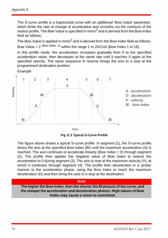
Appendix E
The S-curve profile is a trapezoidal curve with an additional 'Bow Value' parameter,which limits the rate of change of acceleration and smooths out the contours of themotion profile. The Bow Value is specified in mm/s3 and is derived from the Bow Indexfield as follows:
The Bow Value is applied in mm/s3 and is derived from the Bow Index field as follows:
Bow Value = 2 (Bow Index -1) within the range 1 to 262144 (Bow Index 1 to 18).
In this profile mode, the acceleration increases gradually from 0 to the specifiedacceleration value, then decreases at the same rate until it reaches 0 again at thespecified velocity. The same sequence in reverse brings the axis to a stop at theprogrammed destination position.
Example
Fig. E.3 Typical S-Curve Profile
The figure above shows a typical S-curve profile. In segment (1), the S-curve profiledrives the axis at the specified Bow Index (BI) until the maximum acceleration (A) isreached. The axis continues to accelerate linearly (Bow Index = 0) through segment(2). The profile then applies the negative value of Bow Index to reduce theacceleration to 0 during segment (3). The axis is now at the maximum velocity (V), atwhich it continues through segment (4). The profile then decelerates in a similarmanner to the acceleration phase, using the Bow Index to reach the maximumdeceleration (D) and then bring the axis to a stop at the destination.
Note
The higher the Bow Index, then the shorter the BI phases of the curve, and the steeper the acceleration and deceleration phases. High values of Bow
Index may cause a move to overshoot.
BI BI
A D
-BI -BI
V
Time
Velo
city
1 2 3 4 5 6 7
A - accelerationD - decelerationV - velocityBI - bow index
74 HA0362T Rev C Jan 2017

K-Cube Stepper Motor Controller
E.2 Positioning a Stage
E.2.1 GeneralWhenever a command is received to move a stage, the movement is specified inmotion units, (e.g. millimetres). This motion unit value is converted to microstepsbefore it is sent to the stage by the APT software.
Each motor in the system has an associated electronic counter in the controller, whichkeeps a record of the net number of microsteps moved. If a request is received toreport the position, the value of this counter is converted back into motion units.
E.2.2 Home positionWhen the system is powered up, the position counters in the controller are all set tozero and consequently, the system has no way of knowing the position of the stagein relation to any physical datum.
A datum can be established by sending all the motors to their ‘Home’ positions. The‘Home’ position is set during manufacture and is determined by driving the motor untilthe negative limit switch is reached and then driving positively a fixed distance (zerooffset). When at the Home position, the counters are reset to zero therebyestablishing a fixed datum that can be found even after the system has been switchedoff.
See Section 5.3. for details on performing a Home move.
E.2.3 Limit SwitchesA linear stage moves between two stops, and movement outside these limits isphysically impossible. Linear stages can include stages that control the angle of aplatform within a certain range, although the movement of the platform is not reallylinear but angular. Rotary stages can rotate indefinitely, like a wheel.
Linear and rotary stages can contain microswitches that detect certain positions of thestage, but they differ in the way these switches are used.
All linear stages have a –ve limit switch, to prevent the stage from accidentally beingmoved too far in the –ve direction. Once this switch is activated, movement stops. Theswitch also provides a physical datum used to find the Home position. Some linearstages and actuators also have a +ve limit switch (such as the ZST range ofactuators), whereas others rely on a physical stop to halt the motion in the positivedirection. A rotary stage has only one switch, used to provide a datum so that the
75

Appendix E
Home position can be found. Movement is allowed right through the switch position ineither direction.
Fig. E.4 Stage limit switches
E.2.4 Minimum and Maximum PositionsThese positions are dependent upon the stage or actuator to which the motors arefitted, and are defined as the minimum and maximum useful positions of the stagerelative to the ‘Home’ position - see Fig. E.5.
The distance from the Minimum position to the Maximum position is the ‘useful travel’of the stage. It is often the case that the Minimum position is zero. The Home andMinimum positions then coincide, with movement always occurring on the positiveside of the Home position.
Rotary stages have effectively no limits of travel. The Minimum and Maximumpositions are conventionally set to 0 and 360 degrees respectively. When the positionof a rotary stage is requested, the answer will be reported as a number between 0 and360 degrees, measured in the positive direction from the Home position.
Fig. E.5 Minimum and Maximum Positions
Rotary stageLinear stage
Datum switch
-ve limit switch +ve limit switch(or stop)
Travel
Min. position (zero)(home)
Max. position
Offset
-ve limit switch
SW positive limitSW negative limit
76 HA0362T Rev C Jan 2017
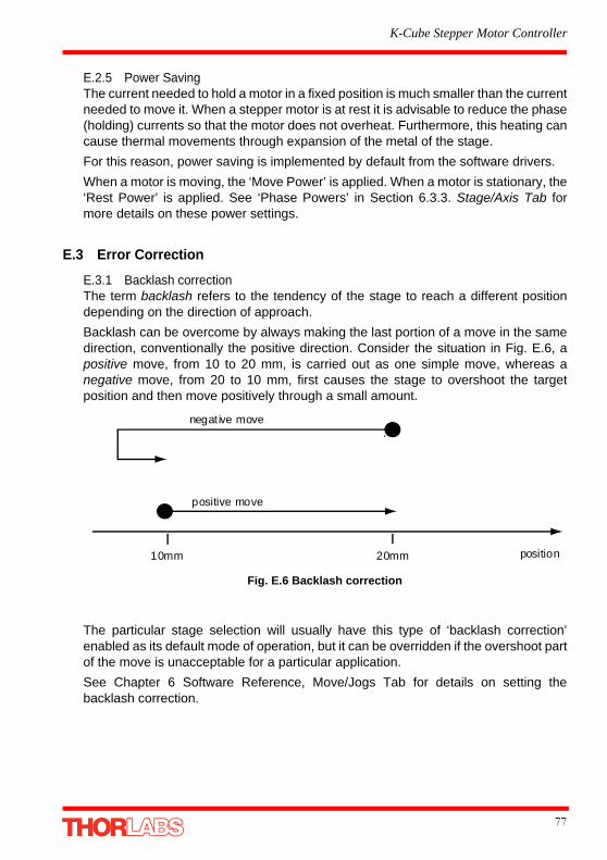
K-Cube Stepper Motor Controller
E.2.5 Power SavingThe current needed to hold a motor in a fixed position is much smaller than the currentneeded to move it. When a stepper motor is at rest it is advisable to reduce the phase(holding) currents so that the motor does not overheat. Furthermore, this heating cancause thermal movements through expansion of the metal of the stage.
For this reason, power saving is implemented by default from the software drivers.
When a motor is moving, the ‘Move Power’ is applied. When a motor is stationary, the‘Rest Power’ is applied. See ‘Phase Powers’ in Section 6.3.3. Stage/Axis Tab formore details on these power settings.
E.3 Error Correction
E.3.1 Backlash correctionThe term backlash refers to the tendency of the stage to reach a different positiondepending on the direction of approach.
Backlash can be overcome by always making the last portion of a move in the samedirection, conventionally the positive direction. Consider the situation in Fig. E.6, apositive move, from 10 to 20 mm, is carried out as one simple move, whereas anegative move, from 20 to 10 mm, first causes the stage to overshoot the targetposition and then move positively through a small amount.
Fig. E.6 Backlash correction
The particular stage selection will usually have this type of ‘backlash correction’enabled as its default mode of operation, but it can be overridden if the overshoot partof the move is unacceptable for a particular application.
See Chapter 6 Software Reference, Move/Jogs Tab for details on setting thebacklash correction.
negat ive move
positive move
10mm 20mm position
77

Appendix F Regulatory
F.1 Declarations Of Conformity
F.1.1 For Customers in EuropeSee Section F.3.
F.1.2 For Customers In The USAThis equipment has been tested and found to comply with the limits for a Class Adigital device, persuant to part 15 of the FCC rules. These limits are designed toprovide reasonable protection against harmful interference when the equipment isoperated in a commercial environment. This equipment generates, uses and canradiate radio frequency energy and, if not installed and used in accordance with theinstruction manual, may cause harmful interference to radio communications.Operation of this equipment in a residential area is likely to cause harmful interferencein which case the user will be required to correct the interference at his own expense.
Changes or modifications not expressly approved by the company could void theuser’s authority to operate the equipment.
F.2 Waste Electrical and Electronic Equipment (WEEE) Directive
F.2.1 ComplianceAs required by the Waste Electrical and Electronic Equipment (WEEE) Directive ofthe European Community and the corresponding national laws, we offer all end usersin the EC the possibility to return "end of life" units without incurring disposal charges.
This offer is valid for electrical and electronic equipment
• sold after August 13th 2005 • marked correspondingly with the crossed out "wheelie bin" logo (see Fig. 1)• sold to a company or institute within the EC • currently owned by a company or institute within the EC • still complete, not disassembled and not contaminated
78

K-Cube Stepper Motor Controller
Fig. F.1 Crossed out "wheelie bin" symbol
As the WEEE directive applies to self contained operational electrical and electronicproducts, this "end of life" take back service does not refer to other products, such as
• pure OEM products, that means assemblies to be built into a unit by the user (e. g. OEM laser driver cards)
• components • mechanics and optics • left over parts of units disassembled by the user (PCB's, housings etc.).
If you wish to return a unit for waste recovery, please contact Thorlabs or your nearestdealer for further information.
F.2.2 Waste treatment on your own responsibilityIf you do not return an "end of life" unit to the company, you must hand it to a companyspecialized in waste recovery. Do not dispose of the unit in a litter bin or at a publicwaste disposal site.
F.2.3 Ecological backgroundIt is well known that WEEE pollutes the environment by releasing toxic productsduring decomposition. The aim of the European RoHS directive is to reduce thecontent of toxic substances in electronic products in the future.
The intent of the WEEE directive is to enforce the recycling of WEEE. A controlledrecycling of end of life products will thereby avoid negative impacts on theenvironment.
79

Appendix F
F.3 CE Certificate
80 HA0362T Rev C Jan 2017
K-Cube Stepper Motor Controller
Appendix G Thorlabs Worldwide ContactsUSA, Canada, and South AmericaThorlabs, Inc.56 Sparta AveNewton, NJ 07860USATel: 973-579-7227Fax: 973-300-3600www.thorlabs.comwww.thorlabs.us (West Coast)email: [email protected]: [email protected]
EuropeThorlabs GmbHHans-Böckler-Str. 685221 DachauGermanyTel: +49-(0)8131-5956-0Fax: +49-(0)8131-5956-99www.thorlabs.deemail: [email protected]
UK and IrelandThorlabs Ltd.1 Saint Thomas Place, ElyCambridgeshire CB7 4EXGreat BritainTel: +44 (0)1353-654440Fax: +44 (0)1353-654444www.thorlabs.deemail: [email protected]: [email protected]
FranceThorlabs SAS109, rue des Côtes78600 Maisons-LaffitteFranceTel: +33 (0) 970 444 844Fax: +33 (0) 811 381 748www.thorlabs.deemail: [email protected]
ScandinaviaThorlabs Sweden ABBergfotsgatan 7431 35 MölndalSwedenTel: +46-31-733-30-00Fax: +46-31-703-40-45www.thorlabs.deemail: [email protected]
JapanThorlabs Japan Inc.Higashi IkebukuroQ Building 1st Floor 2-23-2Toshima-ku, Tokyo 170-0013JapanTel: +81-3-5979-8889Fax: +81-3-5979-7285www.thorlabs.jpemail: [email protected]
ChinaThorlabs ChinaOasis Middlering Centre3 Building 712 Room915 Zhen Bei RoadShanghaiChinaTel: +86 (0)21-32513486Fax: +86 (0)21-32513480www.thorlabs.comemail: [email protected]
BrazilThorlabs Vendas de Fotônicos Ltda.Rua Riachuelo, 171São Carlos, SP 13560-110BrazilTel: +55-16-3413 7062Fax: +55-16-3413 7064www.thorlabs.comEmail: [email protected]
81

Thorlabs Ltd.Saint Thomas Place, ElyCambridgeshire CB7 4EX, UKTel: +44 (0) 1353 654440Fax: +44 (0) 1353 654444www.thorlabs.com
Thorlabs Inc.56 Sparta AveNewton, NJ07860USATel: +1 973 579 7227Fax: +1 973 300 3600www.thorlabs.com
82