kontraktbilag 1k building interface document dcpt
TRANSCRIPT

Sagsnr. 1‐23‐4‐72‐19‐15 Udbudsmateriale ‐ Offentligt udbud Udbud af arbejdsmiljøkoordinering til DNU Kontraktbilag 1K
Kontraktbilag 1K
Building Interface Document ‐ DCPT

Particle Therapy Building Interface Document (BID)
Version 2.9
Feb 2014

© 2014 Copyright Varian Medical Systems, Inc.. Any review, disclosure, copying or distribution of the content of this document or portion thereof is strictly prohibited. All rights reserved.
Varian CONFIDENTIAL Page 2 of 81
This document is available in both printed and digital form (Adobe Acrobat .PDF format). The Applicable Drawings Files listed in this document are available in PDF format. Limitation of Liability Every effort has been made to keep the Applicable Drawings Files and other documents referred to herein (the “Files and/or Documents”) consistent with the provisions of the BID. Notwithstanding such efforts, such Files and/or Documents are provided “as is” without warranty of any kind, either express or implied, including the implied warranties of merchantability and fitness for a particular purpose. To the extent that any modifications to the Files and/or Documents are required to reflect any site-specific conditions and/or regulatory agency requirements, the Architects and Engineers of Record shall be responsible for such modifications and the accuracy and completeness thereof. Varian shall not be liable for the accuracy or completeness of the Files and/or Documents, any documents that include portions of or are created in reliance on the Files and/or Documents or any damages, direct, indirect, incidental or consequential, including damages for any lost profits or project delays that result from the use of the Files and/or Documents included or referred to herein. Varian, Varian Medical Systems, the Varian Medical Systems logo, and ARIA are registered trademarks and Eclipse is a trademark of Varian Medical Systems, Inc. The names of other companies and products mentioned herein are used for identification purposes only and may be trademarks or registered trademarks of their respective owners. To obtain a printed copy of this document or the Applicable Drawings, or if you have any questions, please contact the Varian Particle Therapy Building Interface Manager. Particle Therapy Building Interface Manager Varian Medical Systems 3100 Hansen Way, Palo Alto, CA 94304 Phone: +1 650-559-5949 E-mail: [email protected]

© 2014 Copyright Varian Medical Systems, Inc.. Any review, disclosure, copying or distribution of the content of this document or portion thereof is strictly prohibited. All rights reserved.
Varian CONFIDENTIAL Page 3 of 81
Table of Contents 1 Introduction ...................................... ........................................................................... 8
1.1 Abbreviations and Definitions ..................... .............................................................. 8
1.2 Purpose of This Document .......................... .............................................................. 8
1.3 Scope ............................................. .............................................................................. 9
1.4 Review and Coordination ........................... ................................................................ 9
2 Disclaimers ....................................... ........................................................................ 10
2.1 Radiation Shielding ............................... ................................................................... 10
2.2 Fire Protection ................................... ....................................................................... 10
2.3 Refurbishment of Walls and Floors after Installatio n ............................................. 10
2.4 Waste Disposal and Recycling, Intermediate Storage ........................................... 10
2.5 Utilities and Consumables ......................... .............................................................. 10
2.6 Adverse Weather ................................... ................................................................... 10
2.7 Seismic Engineering ............................... ................................................................. 10
2.8 Permits and Other Requirements .................... ........................................................ 10
2.9 Changes to the Facility ........................... .................................................................. 11
3 Radiation Safety .................................. ...................................................................... 12
3.1 Radiation Permits ................................. .................................................................... 12
3.2 Comments on the Drawings Provided with the BID .... ........................................... 13
3.3 Radiation Monitoring Equipment .................... ......................................................... 13
3.4 Block Walls and Removable Shielding Blocks ........ ............................................... 13
4 Space Requirements ................................ ................................................................ 15
4.1 Cyclotron Area .................................... ...................................................................... 17
4.1.1 Pit Underneath the Cyclotron ...................................................................................... 17
4.1.2 Entrance Hatch and Airspace above Cyclotron ........................................................... 18
4.2 ESS and BTS ....................................... ...................................................................... 18
4.3 Gantry Rooms ...................................... ..................................................................... 19
4.3.1 Patient Area and X-ray Alcove .................................................................................... 19
4.4 Fixed Beam Treatment Room ......................... ......................................................... 19
4.4.1 Horizontal FBR – Version 1 ........................................................................................ 19
4.4.2 Horizontal FBR – Version 2 ........................................................................................ 19
4.4.3 End of Line Eye Treatment room ................................................................................ 20
4.4.4 Patient Area and X-ray Alcove .................................................................................... 20
4.5 Electrical Rooms .................................. ..................................................................... 20
4.5.1 Cyclotron Electrical Room ........................................................................................... 20
4.5.2 Diagnostic Room ........................................................................................................ 21
4.5.3 Magnet Power Supply Room and ESS power supply room ......................................... 21
4.6 Control Rooms ..................................... ..................................................................... 21
4.6.1 Main Control Room ..................................................................................................... 22
4.6.2 Treatment Control Room(s) ........................................................................................ 22
4.7 Technical Gases and Cryogenic Compressor Room ..... ........................................ 22
4.8 Mechanical and Electrical Workshop ................ ...................................................... 22
4.9 Vacuum Workshop ................................... ................................................................ 23
4.10 Storage Room ...................................... ..................................................................... 23
4.11 Server Rooms ...................................... ..................................................................... 23
4.12 Maintenance Offices ............................... .................................................................. 23
4.13 Treatment Planning Room ........................... ............................................................ 23
4.14 Immobilization Device Storage ..................... ........................................................... 23
4.15 Quality Assurance Equipment Storage ............... .................................................... 23
4.16 Film Development Laboratory ....................... .......................................................... 24
5 Installation and Maintenance Requirements ......... ................................................. 25
5.1 Installation and Commissioning .................... .......................................................... 25
5.2 Building Ready Milestones ......................... ............................................................. 25
5.2.1 Building Ready for Equipment Insertion (RFE) ............................................................ 25
5.3 Staging of Equipment .............................. ................................................................. 26

© 2014 Copyright Varian Medical Systems, Inc.. Any review, disclosure, copying or distribution of the content of this document or portion thereof is strictly prohibited. All rights reserved.
Varian CONFIDENTIAL Page 4 of 81
5.4 Insertion of Equipment ............................ ................................................................. 26
5.5 Insertion of Cyclotron and Gantries ............... ......................................................... 27
5.6 Installation of Heavy Magnets in the BTS and ESS .. .............................................. 29
5.7 Installation of Devices in the Fixed Beam Rooms ... ............................................... 30
5.8 Installation of Large Electrical Cabinets ......... ........................................................ 30
5.9 Permanently Installed Cranes in Building .......... ..................................................... 30
5.10 Freight Elevator Requirements ..................... ........................................................... 31
5.11 Permanently Installed Maintenance Platforms ....... ................................................ 31
5.11.1 Cyclotron Platforms .................................................................................................... 31
5.11.2 Gantry Room Platforms .............................................................................................. 31
5.11.3 Fixed Beam Room Pit Cover....................................................................................... 31
5.11.4 Outside Platforms ....................................................................................................... 31
5.11.5 Other Platforms .......................................................................................................... 32
5.12 Rigging Openings in Shielding Walls ............... ....................................................... 32
5.13 Doors to Non-Radiation Areas ...................... ........................................................... 32
5.14 Doors to Radiation Areas .......................... ............................................................... 33
5.15 Structural Requirements for Walls and Floors Loads ............................................ 33
5.15.1 Cyclotron Room .......................................................................................................... 33
5.15.2 ESS and BTS ............................................................................................................. 33
5.15.3 Gantry Room .............................................................................................................. 34
5.15.4 Access Floors and Trench Systems ............................................................................ 34
5.15.5 Surrounding Areas ...................................................................................................... 36
5.16 Specific Structural Stability Requirements ........ ..................................................... 36
5.16.1 Load Supporting Embedded Objects .......................................................................... 36
5.16.2 Embedded Cooling Water and Technical Gas Pipes ................................................... 38
5.16.3 Conduits ..................................................................................................................... 39
6 Building Tolerances and Equipment Alignment ....... .............................................. 42
6.1 Building Settlement ............................... ................................................................... 42
6.2 Civil Engineering and Construction Tolerances ..... ................................................ 42
6.3 Vibration Effects ................................. ...................................................................... 42
6.4 Building Initial Geodetic Survey .................. ............................................................ 42
6.4.1 Pre-alignment ............................................................................................................. 42
6.4.2 Reference Network ..................................................................................................... 43
6.4.3 RFE Requirements ..................................................................................................... 44
6.4.4 Alignment Tubes ......................................................................................................... 44
7 Electrical System Requirements .................... ......................................................... 45
7.1 Connected Load .................................... .................................................................... 46
7.2 Connection Points ................................. ................................................................... 46
7.2.1 Europe (or other 50Hz environments) ......................................................................... 49
7.2.2 USA (or other 60Hz environments) ............................................................................. 50
7.3 Compensation System and Harmonic Filtering ........ .............................................. 51
7.4 Annual Electrical Energy Consumption .............. .................................................... 51
7.5 UPS and Emergency Power ........................... .......................................................... 51
7.6 Lightning Protection and Grounding ................ ...................................................... 52
7.7 Special Signal Grounding .......................... .............................................................. 53
7.8 Lighting Requirements ............................. ................................................................ 53
7.8.1 Treatment Room – Patient Area ................................................................................. 53
7.9 Cable Trays ....................................... ........................................................................ 53
7.10 Conduits in shielding walls ....................... ............................................................... 54
7.11 Special Cable Run Requirements .................... ........................................................ 55
7.11.1 Wall Feed-Throughs ................................................................................................... 55
7.11.2 Magnet Power Supply Room – Treatment Room ........................................................ 56
7.11.3 Cyclotron Area – Cyclotron Electrical Room ............................................................... 56
7.11.4 Gantry – BTS (Beam Passage) ................................................................................... 56
7.11.5 Gantry – BTS (Cable Trays) ....................................................................................... 56
7.11.6 Main Control Room ..................................................................................................... 57

© 2014 Copyright Varian Medical Systems, Inc.. Any review, disclosure, copying or distribution of the content of this document or portion thereof is strictly prohibited. All rights reserved.
Varian CONFIDENTIAL Page 5 of 81
7.11.7 Between Electrical Rooms .......................................................................................... 57
7.11.8 Control Rooms and Cable Trays ................................................................................. 57
8 Cooling Water Requirements ........................ ........................................................... 58
8.1 Secondary System .................................. .................................................................. 58
8.2 Primary Loops ..................................... ..................................................................... 58
8.2.1 Special Requirements for RF Amplifier type TH .......................................................... 62
8.3 Mechanical Interface .............................. .................................................................. 62
8.4 Control System Interface .......................... ............................................................... 62
8.5 Water Supply ...................................... ....................................................................... 62
8.6 Waste Water ....................................... ....................................................................... 63
8.6.1 Work shops ................................................................................................................. 63
8.6.2 Electrical rooms .......................................................................................................... 63
9 HVAC Requirements ................................. ................................................................ 64
9.1 General Room Air Requirements ..................... ........................................................ 64
9.2 Cyclotron Area Air Supply ......................... .............................................................. 65
9.3 Helium Gas Exhaust and Pressure Relief During Quenc h ..................................... 66
9.4 Vacuum Pump Exhaust ............................... ............................................................. 68
9.5 Air Activation .................................... ........................................................................ 68
9.6 Workshop Exhaust .................................. ................................................................. 68
10 Specialty Gas Requirements ........................ ............................................................ 69
10.1 Oxygen ............................................ .......................................................................... 69
10.2 Nitrogen .......................................... ........................................................................... 70
10.2.1 Cyclotron Pit ............................................................................................................... 70
10.3 Hydrogen .......................................... ......................................................................... 71
10.4 Technical Compressed Air .......................... ............................................................. 71
11 Electromagnetic and Magnetic Field Interference ... ............................................... 73
12 Telecommunications and Networking ................. .................................................... 73
12.1 Danger Warning and Alarm Systems .................. .................................................... 74
12.2 IT Networks ....................................... ........................................................................ 74
12.2.1 Racks ......................................................................................................................... 76
12.2.2 Optical Fiber Network ................................................................................................. 77
12.2.3 CAT 6 Copper Network ............................................................................................... 78
12.2.4 Wall outlets ................................................................................................................. 78
12.2.5 IP Addresses .............................................................................................................. 79
12.2.6 Internet Access ........................................................................................................... 80
12.2.7 Parts Availability ......................................................................................................... 80
12.2.8 ARIA and ECLIPS ....................................................................................................... 80
13 Fire Protection ................................... ....................................................................... 81
13.1 Sprinkler System .................................. .................................................................... 81
13.2 Fire Walls and Fire Stopping in Feed-Throughs ..... ................................................ 81
13.3 Fire-Retardant Materials .......................... ................................................................. 81

© 2014 Copyright Varian Medical Systems, Inc.. Any review, disclosure, copying or distribution of the content of this document or portion thereof is strictly prohibited. All rights reserved.
Varian CONFIDENTIAL Page 6 of 81
Appendices That Are Part of This BID Documen t No. Title Particle Therapy Building Interface Document - List of drawings Appendix 1 Sample Data Interchange between BDCT and Varian Appendix 2 Sample hydraulic data sheet for process cooling water interfaces Appendix 3 Sample List of Conduits Appendix 4 Design description Fixed beam cover

© 2014 Copyright Varian Medical Systems, Inc.. Any review, disclosure, copying or distribution of the content of this document or portion thereof is strictly prohibited. All rights reserved.
Varian CONFIDENTIAL Page 7 of 81
List of Tables Table 1. List of rooms to be provided by BDCT for PTE .............................................................. 15
Table 2. Temporary space requirements checklist ...................................................................... 16
Table 3. Path for insertion of PTE ............................................................................................... 27
Table 4. Examples of mobile cranes ........................................................................................... 28
Table 5. Excerpt from DIN 18202 regarding evenness ................................................................ 30
Table 6. Permanent cranes and elevator to be installed inside the building ................................ 30
Table 7. Double floor and trench systems ................................................................................... 35
Table 8. BDCT-supplied load supporting embedded objects ....................................................... 38
Table 9. Minimum Radius of Conduits according to NEC ............................................................ 39
Table 10. Cross-reference of conduit and interface points in lists with BID drawings .................. 41
Table 11. Limit values of individual harmonic voltages at the hook-up points as percentage of Un
............................................................................................................................................ 45
Table 12. Typical EN 61000 requirements on power quality ........................................................ 45
Table 13. Example of electrical connection data of plug-in bus way. ........................................... 48
Table 14. 50 Hz: Connected electrical load hook-up points according to room ............................ 49
Table 15. 60 Hz: Hook-up points required, exclusive use for PTE ............................................... 50
Table 16. Overview on the primary cooling water loops .............................................................. 61
Table 17. Heat transfer to the air from power supply units and warm system parts ..................... 64
Table 18. Heat transfer to the air from subdivided power supply rooms ...................................... 64
Table 19. Hazardous materials ................................................................................................... 71
Table 20. Network Jacks ............................................................................................................. 79
List of Figures Figure 1. Example of cable raceway ........................................................................................... 22
Figure 2. Alternative rigging crane for the Cyclotron.................................................................... 28
Figure 3. Standard insulated façade element with tongue and groove, usable for temporary roof ............................................................................................................................................ 29
Figure 4. Typical access floor ..................................................................................................... 34
Figure 5. Steel mounting plates for magnets ............................................................................... 43
Figure 6. Ball mounting assemblies for permanent installation; center and right also show an SMR (triple mirror) ............................................................................................................... 43
Figure 7. Installation of SMR floor base ...................................................................................... 44
Figure 8. Typical 5-conductor plug-in bus way ............................................................................ 47
Figure 9. Examples of cable ladders ........................................................................................... 54
Figure 10. Examples of cable trays ............................................................................................. 54
Figure 11. Overview for feed-throughs, cable trays, and services ............................................... 55
Figure 12. Water cooling circuits ................................................................................................. 58
Figure 13. Typical RF load profile in kW 24h time scale .............................................................. 59
Figure 14. Typical RF load profile in kW 1h time scale ................................................................ 60
Figure 15. Typical RF load profile in kW 5min time scale ............................................................ 60
Figure 16. Recommended quench tube elbows .......................................................................... 66
Figure 17. Vertical quench tube outlet to atmosphere ................................................................. 67
Figure 18. Hydrogen generator and manifold .............................................................................. 69
Figure 19 Cyclotron magnetic field at the isocenter plane ........................................................... 73
Figure 20 Magnetic field of 135° dipole magnet moun ted on rational gantry ............................... 73
Figure 21 Room naming convention for PTx operational network (TL) ........................................ 75
Figure 22 Room naming convention for PTx operational network (UL)........................................ 76
Figure 23 Possible location of wall-mount cabinet in BTS ........................................................... 77
Figure 24 Pre-terminated AMP MPO fiber trunk .......................................................................... 77
Figure 25 CAT6 termination with AMP SL series jacks (Stagger Left or Stagger Right) .............. 78

© 2014 Copyright Varian Medical Systems, Inc.. Any review, disclosure, copying or distribution of the content of this document or portion thereof is strictly prohibited. All rights reserved.
Varian CONFIDENTIAL Page 8 of 81
1 Introduction
1.1 Abbreviations and Definitions BDCT Building design and construction team – general term for the team responsible for
construction and its suppliers, including the customer, but not including Varian BID Building interface document – the latest revision of this document BTS Beam transport system – this is part of the beam line after the ESS where the beam is
transferred to each treatment room ESS Energy selection system – this is part of the beam line directly after the cyclotron FBR Fixed beam room HVAC Heating, venting, air conditioning LL Lower level (one level below TL) MEP Mechanical, electrical, plumbing equipment (building services), without PTE or medical
equipment MPSR Magnet Power Supply Room NEC US National Electrical Code, in its current Edition NCRP National Council on Radiation Protection, a non-governmental organization in the US PSR Power Supply Room PT Proton therapy PTE Proton therapy equipment – general term for the contractual scope of Varian RF Radio frequency RFE Ready for equipment SD Sub-distribution cabinet – normally refers to electrical installations TL Treatment level (typically ground level, but may be below grade if applicable); level 0.0 UL Upper level (one level above TL) UPS Uninterruptable power supply US FDA United States Food and Drug Administration For the purpose of this document, the terms computer floor, access floor, recessed floor, and raised floor are used interchangeably.
1.2 Purpose of This Document Each Proton Therapy Center is unique and presents different challenges. Layout of and access to the available land, soil bearing capacity, water table height, vibrations from nearby, connections to other buildings are just some examples of project specific issues that need to be balanced to provide the best solution for the specific project site. The key challenge of the BDCT is to accommodate Varian’s requirements and the unique site requirements into a building while creating a patient and user-friendly environment allowing an efficient clinical work-flow. This document defines the building interface requirements for the ProBeamTM Varian Proton Therapy Delivery System. These requirements need to be fulfilled by the BDCT to enable installation, commissioning, operation, and maintenance of the system. Requirements in this document extend to BDCT deliverables that affect PTE functionality. Varian provides proton therapy equipment. This equipment is installed in a building that is designed and realized by the BDCT. The building must be designed based on Varian requirements and must conform to local regulations, especially regulations on radiation safety. Varian proposes two building configurations which differ mainly by the location of the Varian electrical rooms. In configuration A the electrical rooms are located above the cyclotron and treatment room mazes. In configuration B the Varian electrical rooms are located above the ESS and BTS. Based on the Customer’s available space, Varian will propose one of these configurations in a specific project and provide a list of drawings that apply to this configuration. The standard building development process will include the following aspects and assumptions:
• The customer’s building will conform to all Varian requirements that are stated in this Building Interface Document and respective drawings. This document shall be valid in its current revision and will not be adapted to the specific customer. Deviations from the BID are possible but must be evaluated and approved by Varian.
• Equipment scope changes may result in changed building requirements.

© 2014 Copyright Varian Medical Systems, Inc.. Any review, disclosure, copying or distribution of the content of this document or portion thereof is strictly prohibited. All rights reserved.
Varian CONFIDENTIAL Page 9 of 81
• Varian will be allowed to occupy the customer’s building according to the agreed schedule. Building occupation means that the areas for Varian equipment must conform to certain cleanliness requirements and that all building systems are operational.
• This document is based on the assumption that the switchover between two treatment rooms must
be realized within 1 minute. Electric loads, cooling loads, and space requirements may change with shorter switchover times.
• This document assumes a beam line height above treatment floor level of 125 cm (49.213”).
Possible ramps and steps between the building parts must be defined during the building design process.
1.3 Scope
This document covers requirements for the ProBeam Proton Therapy System and does not include requirements for conventional X-ray therapy imaging equipment or hardware related to these systems, and it does not include the requirements for ARIA and ECLIPSE software packages.. For the purpose of this document, the drawings 175X-02.01.00-028 and 175X-02.01.00-029 or 175B-02.01.00-029 must be deemed the valid building concept. Unless otherwise noted, all units are metric. Note that 1 t (metric) is equivalent to approx. 2200 lbs. Dimensions, floor loadings, and other metric values will be adjusted to standard U.S. values in coordination between Varian and BDCT, if applicable. Requirements to be fulfilled by the BDCT are explained in the text and/or listed in separate tables at the end of a section.
1.4 Review and Coordination Varian reserves the right to review all BDCT drawings and any facility design documents that are related to the building’s interface with the PTE. This review will be conducted during pre-construction on the final design development documents. In this review, Varian will verify that all requirements in this BID have been properly implemented. If this is not the case, Varian will require changes to properly fulfill the requirements in this BID. This review shall not relieve the BDCT from fulfilling the requirements detailed in this BID. Prior to building occupancy by Varian, the BID will be used to verify compliance of the construction and installations and determine facility readiness for PTE.

© 2014 Copyright Varian Medical Systems, Inc.. Any review, disclosure, copying or distribution of the content of this document or portion thereof is strictly prohibited. All rights reserved.
Varian CONFIDENTIAL Page 10 of 81
2 Disclaimers
2.1 Radiation Shielding The wall and ceiling thicknesses of cast concrete as well as concrete block walls provided in the drawings are for illustration purposes only. Radiation shielding calculations are the sole responsibility of the BDCT.
2.2 Fire Protection Throughout this document, and especially in section 13, Varian provides advice on materials, sensors, and means of fire suppression. It remains the responsibility of the BDCT to design and adhere to code requirements. Varian assumes no liability for compliance with the applicable regulations.
2.3 Refurbishment of Walls and Floors after Install ation
During installation of PTE, the facility, especially floors, walls, doors and furniture, will receive minor damage as part of the normal wear and tear associated with this work. Varian will not be responsible for such minor damage and will not refurbish the facility. All such refurbishing work must be delivered by the BDCT and coordinated with Varian.
2.4 Waste Disposal and Recycling, Intermediate Stor age Waste disposal and recycling, storage of Varian equipment on site are the responsibility of the BDCT. Varian will require space inside the building for an indefinite period of time, free of charge, for activated parts. The costs will be borne by BDCT. The BDCT shall free of charge:
1. provide equipment and material storage space during construction, installation and commissioning 2. provide periodic and final cleanup as coordinated with Varian 3. remove and dispose of Varian shipping crates and packing material 4. provide proper storage and disposal of radio activated parts or media in accordance with local
regulatory requirements
2.5 Utilities and Consumables Provision of mechanical and electrical utilities and consumables are the responsibility of the BDCT. The costs will be borne by BDCT. The BDCT shall free of charge:
1. provide and operate mechanical/electrical systems as required for room occupancy including plumbing, fire protection systems, heating venting and air conditioning, compressed air, lighting and power distribution.
2. provide and connect mechanical/electrical utilities as required for PTE installation, commissioning and operation.
3. provide and connect consumables such as technical gases (nitrogen, oxygen, compressed air).
2.6 Adverse Weather The transport of the equipment into the building may be delayed due to bad weather, or if the road and site conditions do not provide sufficient ground stability due to any reason, including adverse weather. The guarantee of the required installation temperature range in the building with the temporary roof is critical in allowing the installation deadline to be met. The temporary roof must be capable of maintaining the inside air requirements under all weather conditions. This means that the temporary roof structure must have thermal insulation yet remain easily opened and closed.
2.7 Seismic Engineering All aspects of local seismic considerations are the responsibility of the BDCT, unless specifically mentioned otherwise.
2.8 Permits and Other Requirements All permits required by local, state, or federal regulations shall be provided by the BDCT. Excluded from this is the export permit from Germany as well as transport permits on public traffic areas.

© 2014 Copyright Varian Medical Systems, Inc.. Any review, disclosure, copying or distribution of the content of this document or portion thereof is strictly prohibited. All rights reserved.
Varian CONFIDENTIAL Page 11 of 81
2.9 Changes to the Facility All changes in areas where PTE is installed must be approved by Varian. The layout of the equipment must not be changed under any circumstance by the BDCT. The relative positions of all elements of the proton therapy system are a fundamental property of this medical device. The presented layouts are concept drawings and not execution drawings. Varian and BDCT will develop and agree to the final drawings as part of the site development process. Not included in the scope of work are changes due to:
• Requirements resulting from radiation shielding calculations or regulatory requirements. • Customer change requests. • Regulatory requirements leading to change.

© 2014 Copyright Varian Medical Systems, Inc.. Any review, disclosure, copying or distribution of the content of this document or portion thereof is strictly prohibited. All rights reserved.
Varian CONFIDENTIAL Page 12 of 81
3 Radiation Safety Approval by the local regulatory authorities of the radiation safety design of this facility is critical for an efficient construction process. Local requirements differ for each project; therefore a permit-application file must be generated for each new facility. The modular building design allows re-use of existing data and attempts to minimize the need for new shielding calculations. All architectural and engineering works are the responsibility of the BDCT. Varian will support the BDCT with relevant information in the form of documents, drawings, and participation in meetings at an agreed interval.
3.1 Radiation Permits Proton therapy facilities for clinical radiation oncology use particle accelerators such as cyclotrons as a radiation source. These facilities must therefore comply with local, state, and federal regulations for radiation safety. Prior to shipment the customer must hold an appropriate license to receive the cyclotron. Prior to installation, the customer must hold an appropriate operating license for the cyclotron. Due to varying local regulations, Varian requires the customer to obtain permits in the customer’s name. The activities Varian will perform as part of the installation and commissioning of the PTE must be covered by the customer’s operating license issued by the local authorities. Numerous requirements may need to be fulfilled in order to obtain an operating license or even a construction permit. These may include, but are not limited to:
• Construction details of rooms in which radiation is generated or in which radioactive parts are stored.
• Dimensions and shielding materials of walls and floors separating the radiation areas from sections of the building without restrictions caused by radiation regulations.
• Calculations of the expected radiation dose rates at representative points in the building.
• An estimation of expected amounts of radioactive materials activated during operation.
• Description of the planned organization to guarantee radiation safety during operation.
• Installation of radiation monitoring systems.
• Installation of personal dosimetry measurements and documentation of the results. Personal dosimetry required during installation and commissioning will need to be clarified in an agreement between the customer and Varian or its subsidiary suppliers. The standard building layout of a Varian proton therapy system radiation shielding design is based on scaled measured dose rate data from PT equipment in operation. This design is based on the high extraction efficiency of the Varian cyclotron and the conservative assumption that all protons are lost in the ESS. Regulatory agencies may require more evidence. On request, Varian may be able to provide additional radiation shielding calculations to support the permitting process. The radiation shielding design must take into account that maintenance activities must be carried out during operation in designated areas outside the PTE vault. The BDCT is required to:
1. Provide all necessary documentation for license applications and registration applications in coordination with Varian.
2. Perform shielding calculations, environmental impact studies, or similar as required by the respective regulatory bodies.
3. Obtain all necessary radiation licenses and registrations to start construction. 4. Obtain all necessary radiation licenses and registrations to receive activated accelerator parts. 5. Obtain all necessary radiation licenses and registrations to operate PTE in time for commissioning
with beam according to the agreed schedule. 6. Provide Varian estimated radiation levels during operation in all rooms and areas used for
maintenance purposes. Estimated radiation levels are used by Varian to evaluate whether all projected maintenance activities can be carried out.

© 2014 Copyright Varian Medical Systems, Inc.. Any review, disclosure, copying or distribution of the content of this document or portion thereof is strictly prohibited. All rights reserved.
Varian CONFIDENTIAL Page 13 of 81
7. The shielding must be designed so that the maximum permissible dose that any of Varian’s installation, commissioning, or service staff receives outside the shielded area is conforming to the regulatory limits for the general public.
8. The BDCT must consider sky shine for its dose contributions to the public as well as to areas where Varian personnel will be working (for a complete list, see Table 1).
9. Access is required to all Varian electrical rooms, control rooms, and workshops, as well as other mechanical and electrical rooms and the roof area, without the need to shut down the machine to do so. Only qualified personnel shall have access.
10. The following occupancy must be guaranteed by the BDCT to allow installation and maintenance by Varian (occupancy factors (T) are defined by NCRP):
a. All control rooms: T=1. b. All electrical rooms (magnet power supply room, FBR power supply room, diagnostic, ESS
power supply room, technical gases, cyclotron electrical) and workshops: T= 1/10. c. Other mechanical/electrical rooms, unattended waiting rooms, and storage areas: T=1/20. d. Roof areas: T=1/40.
3.2 Comments on the Drawings Provided with the BID Varian does not claim that the drawings referenced in the BID provide adequate shielding thickness. Wall thicknesses are estimated based on experience only. Once radiation-shielding calculations are performed by the BDCT, the layouts must be adapted to fulfill the local radiation safety requirements. The thickness of all radiation-shielding elements (floors, walls, ceilings, block wall elements) must be verified by shielding calculations. The outcome of such calculations and regulatory requirements may require an adjustment of the present layout and/or the shielding material used. The present drawings are provided with an estimate on required shielding thicknesses only and must not be taken as final. It must be noted that the layout of the equipment must not be changed under any circumstance by the BDCT. The relative positions of all elements of the proton therapy system are a fundamental property of this medical device and the basis of our radiation safety estimates. No precautions for ground water or earth activation have been taken into account. The thickness of the floor slab must be defined by the BDCT.
3.3 Radiation Monitoring Equipment Mobile radiation meters for operation during installation and commissioning will be provided by Varian. They will remain the property of Varian. This does not remove the obligation of the BDCT to provide all radiation meters required by local regulatory bodies for system operation. Radiation meters for system operation after installation and commissioning will not be provided by Varian. BDCT and Varian will have to agree on the optimal administrative tasks for personnel dosimetry and local dose monitoring. Stationary radiation measurement must be provided and installed by the BDCT. The equipment might consist of albedo dosimeters placed in polyethylene spheres at critical locations. An electronic dose rate measurement device will be installed by Varian as part of the safety system in the cyclotron / ESS area and will be read out remotely in the main control room. The BDCT is required to:
1. Administer and provide all necessary personnel dosimeters. 2. Conduct all necessary radiation surveys. 3. Install dose and dose rate monitoring equipment as required by the local regulatory bodies, except
patient dose monitors. 4. Provide all shielding calculations, environmental impact studies, etc.
3.4 Block Walls and Removable Shielding Blocks As the ESS is a primary source of neutrons, it is recommended to place concrete blocks near the ESS as indicated in drawing 175X-02.01.00-028. The BDCT is responsible for the provision of shielding and shielding materials, including mobile shields. To minimize air activation and to shield fast neutrons close to the source, while at the same time allowing acceptable maintenance space, the ceiling height in the ESS area shall be 250 cm (8’-2”).

© 2014 Copyright Varian Medical Systems, Inc.. Any review, disclosure, copying or distribution of the content of this document or portion thereof is strictly prohibited. All rights reserved.
Varian CONFIDENTIAL Page 14 of 81
Removable block walls must be used within the cyclotron maze (see drawing 175X-02.01.00-028), as easy access to the cyclotron maze will be required during major equipment repair. Removable block walls must also be used in the opening between BTS and treatment room. Drawing 1291-35.00.00-828 provides guidance on the details of this opening. Other block walls may be constructed in a more permanent way after the equipment installation is complete. Any block wall construction, permanent or removable, must be coordinated with Varian to ensure proper access is still maintained. Additional removable shielding blocks may be needed in the feed-through for the RF transmission line and also in the wall behind the cyclotron’s beam probe. Details are shown in drawings 175A-30.08.04 and 175X-02.01.00-025 or 175B-30.08.04 and 175B-02.01.00-025, depending on power supply room location. For building configuration A only, additional shielding blocks may also be needed in the feed-throughs from the power supply rooms to the treatment rooms, as indicated in drawing 175X-02.01.00-032, or in the feed-through between treatment rooms and BTS (see 175X-30.07.16), if the power supply rooms are located on top of the treatment room maze. Shielding block installation must be coordinated with Varian and installed as scheduled by Varian in order to ensure ability to produce beam. The BDCT is required to:
1. Ensure that the building design conforms to radiation safety regulations. 2. Coordinate block wall installations and installation schedule with Varian. 3. Provide all shielding material, including block walls.
© 2014 Copyright Varian Medical Systems, Inc.. Any review, disclosure, copying or distribution of the content of this document or portion thereof is strictly prohibited. All rights reserved.
Varian CONFIDENTIAL Page 15 of 81
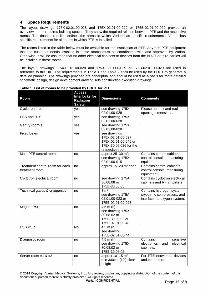
4 Space Requirements The layout drawings 175X-02.01.00-028 and 175X-02.01.00-029 or 175B-02.01.00-029 provide an overview on the required building spaces. They show the required relation between PTE and the respective rooms. The dashed red line defines the areas in which Varian has specific requirements. Varian has specific requirements for all rooms in which PTE is installed. The rooms listed in the table below must be available for the installation of PTE. Any non-PTE equipment that the customer needs installed in these rooms must be coordinated with and approved by Varian. Otherwise, it will be assumed that no other electrical cabinets or devices from the BDCT or third parties will be installed in these rooms. The layout drawings 175X-02.01.00-028 and 175X-02.01.00-029 or 175B-02.01.00-029 are used in reference to this BID. The requirements in Table 1 and Table 2 shall be used by the BDCT to generate a detailed planning. The drawings provided are conceptual and should be used as a basis for more detailed schematic design, design development drawing sets construction execution drawings. Table 1. List of rooms to be provided by BDCT for P TE
Room
Access Interlocks for Radiation Safety
Dimensions Comments
Cyclotron area yes see drawing 175X-02.01.00-028
Please note pit and roof opening dimensions.
ESS and BTS yes see drawing 175X-02.01.00-028
Gantry room(s) yes see drawing 175X-02.01.00-028
Fixed beam yes see drawings 175X-02.01.00-037, 175X-02.01.00-046 or 175X-30.05.026 for the respective room
Main PTE control room no approx 25–30 m²; see drawing 175X-02.01.00-015
Contains control cabinets, control console, measuring equipment.
Treatment control room for each treatment room
no approx 15–20 m² each Contains control cabinets, control console, measuring equipment.
Cyclotron electrical room no see drawing 175A-30.08.08 or 175B-30.08.08
Contains cyclotron electrical cabinets and RF amplifiers.
Technical gases & cryogenics no 8 m²; see drawing 175A-02.01.00-023 or 175B-02.01.00-023
Contains hydrogen system, cryogenic compressors, and interface for oxygen system.
Magnet PSR no 4.5 m (h); see drawing 175X-30.08.02 or 175B-30.08.02 or 175B-02.01.00-48
ESS PSR No 4.5 m (h); see drawing 175B-02.01.00-44
Diagnostic room no 4.5 m (h); see drawing 175X-30.08.02 or 175B-30.08.02
Contains sensitive electronics and electrical cabinets.
Server room #1 & #2 no approx 10–15 m² min 300cm (10’) clear height
For PTE networked devices and computers.

© 2014 Copyright Varian Medical Systems, Inc.. Any review, disclosure, copying or distribution of the content of this document or portion thereof is strictly prohibited. All rights reserved.
Varian CONFIDENTIAL Page 16 of 81
Room
Access Interlocks for Radiation Safety
Dimensions Comments
Mechanical & electrical workshop
no approx 80–100 m²; see drawing 175X-02.01.00-028 min 300cm (10’) clear height
For mechanical and electronics repairs; may be co-used during operation.
Spare parts storage #1 & 2 no approx 30 m² each min 300cm (10’) clear height
High-value spare parts. 1x on TL, 1x on UL. Access only to Varian.
Vacuum workshop no approx 15–20 m²; see drawing 175X-02.01.00-028 min 300cm (10’) clear height
Maintenance of activated parts, measuring equipment, fine tools.
Storage activated parts no approx 20–30 m² min 300cm (10’) clear height
Storage area for activated parts.
1 large Maintenance offices and one smaller maintenance office
no approx 15–20 m² for the small office. The large office shall be 40-60m²;
Permanent office for Varian maintenance support team.
Temporary space requirements: Varian office space, conference room availability, changing rooms, sanitary installations, storage during installation and commissioning
no will be defined depending on local conditions; see checklist below
During installation and commissioning, patient, personnel, or physician areas will be used as office space.
Advisory for other rooms that may be necessary for clinical or quality assurance related purposes
Treatment planning room ARIA® & Eclipse™
no typical dimensions 6 m x 9 m (20’ x 30’) for 6 work places
Please refer to Varian Installation Data Package, Section 5.
Film development lab no < 10 m² For X-ray film development. QA equipment storage no < 10 m² For storage of QA
equipment near the clinical use area.
Immobilization couch storage no depends on storage racks
Immobilization couches for active patients, including disinfection and raw material storage.
Table 2. Temporary space requirements checklist Temporary Space Requirement Approximate Size / Comments During installation: • Office • Conference room • Changing/locker rooms with
sanitary • Covered and secure storage
o Varian components o Electrical parts o Cooling
•
2x 20 m²; also container offices outside building Co-use with customer Male / female for as many as 20 persons Approx. 150 m2; see section 4.10 MEP installation storage may be container storage on site or unfinished clinical areas.

© 2014 Copyright Varian Medical Systems, Inc.. Any review, disclosure, copying or distribution of the content of this document or portion thereof is strictly prohibited. All rights reserved.
Varian CONFIDENTIAL Page 17 of 81
Temporary Space Requirement Approximate Size / Comments • outside staging area • 15-20 parking spaces within
walking distance of the site
approx 1,500m² (15,000 sq.ft) from RFE-2 months until mechanical installation complete.
During commissioning: • Office • Conference room • Changing/locker rooms with
sanitary • Covered and secure storage • 7-10 parking spaces within
walking distance of the site
3x 20 m²; could be immobilization rooms, personnel space Co-use with customer Male / female for as many as 20 persons Approx. 150 m²; will use workshops and free, unfinished office space
4.1 Cyclotron Area
4.1.1 Pit Underneath the Cyclotron
A 240 cm (7’-10.5”) deep pit is required underneath the cyclotron with lateral dimensions as shown in drawing 175X-02.01.00-025. This pit is required for maintenance on the lower pole cap. The cooling water distribution network is also located in this pit; all cooling water pipes interfaces are located here as well. A clearance of 210cm (7’) is required in the pit. Exemptions are only possible within 50cm (20”) of the three walls not containing the stairs. Exemptions must be requested and approved by Varian. Note: Fire sprinkler system piping is not exempt from this requirement. The feet of the cyclotron rest on steel floor plates that are inserted in reinforced recesses of the floor slab and then cemented into place. The steel floor plates must be provided by the BDCT according to Varian specifications. The load is 40 t per foot. The steel plate must be positioned exactly horizontally in position and angle. Anchor plates must be embedded into the walls of the cyclotron pit. Base plates for the feet must be manufactured according to PT06913200. Anchor plates for the walls must be manufactured according to PT06913200. Manufacturing, delivery and installation is the responsibility of the BDCT. Embedded plates must be provided in the walls around the cyclotron in order to install the second level platform shown in drawing 175X-02.01.00-025 and 01-11-2-002. See also

© 2014 Copyright Varian Medical Systems, Inc.. Any review, disclosure, copying or distribution of the content of this document or portion thereof is strictly prohibited. All rights reserved.
Varian CONFIDENTIAL Page 18 of 81
Table 8. All plates must be embedded in the concrete. The installation must be realized with a lateral accuracy for all edges of ±10 mm (1/2”), a vertical accuracy of ±5 mm (1/4”), and a maximum tilt of 2 mm (5/64”) over the respective plate. The plates must installed according to drawing 175A-30.08.07 and PT069132. The drawings show the center of the respective plate as the point of reference for position. Additional information is shown PT068778. Note: The design and anchoring of the foot plates must be verified by the BDCT. Earthquake requirements may change the design of foot plates and require additional anchoring restraints for the cyclotron.
4.1.2 Entrance Hatch and Airspace above Cyclotron
The minimum inside height above the floor level is 550 cm (18’-0”). A transport opening of at least 480 cm x 480 cm (15’-9” x 15’-9”) is required above the cyclotron. Drawing 175X-02.01.00-025 defines the necessary dimensions of the airspace above the cyclotron. A crane must be installed in the open area above the cyclotron with a load-bearing capacity as given in Table 6 and a minimum hook height of 4.6 m (15’) above the TL floor level. The dimensions of required hook travel are defined by drawing 175A-07.03.02. The cyclotron will be inserted through the transport opening in parts no heavier than 90 t and positioned by the outside crane. The crane in the cyclotron area will be used extensively starting at RFE and for maintenance of small components, but must be installed and commissioned before cyclotron components are delivered on site. Cable trays and RF-transmission line feed-throughs enter the cyclotron area above the cyclotron. Requirements on feed-throughs are listed in section 7.11. Varian’s requirements for the cyclotron area are specified in drawing 175X-02.01.00-025 or 175B-02.01.00-025, depending on the building configuration. The floors must be covered with smooth composite floor pavement and sealed with a polyurethane or epoxy layer. Floor and wall finishing must be resistant to abrasion and should be water washable. Note: Special requirements that go beyond the requirements for industrial floors apply in the radiation protection areas. The use of radiation-resistant wall paint (such as polyurethane or epoxy paint) is recommended in the cyclotron and ESS areas.
4.2 ESS and BTS The ceiling height in the ESS area is 250 cm (8’-2.5”). The minimum ceiling height in the BTS area is 300 cm (10’). The dipole magnets of the ESS and the BTS represent a load of approximately 8 t (30° dipole) and 13 t (65° dipole) on a baseplate that is embedded in or installed onto the floor. The base plate position is given in drawing PT068881. This drawing provides generic information for all beam line modules. A configuration specific drawing will be issued by Varian for each system depending on treatment room configuration and will typically not be available before the beam line design for the specific customer is validated. The BDCT shall install all base plates with a lateral accuracy so that the center and each corner of the respective foot plate do not deviate more than +/-10 mm (1/2”) from the ideal position. The height of all base plates in the ESS and BTS must be within 5 mm (1/4”) of the specification in PT06881. The top flat surface of each base plate shall be referenced to the ideal beam line height in the building, and not the actual finished floor level in the BTS. The ideal beam line height in the building will be defined with 1 mm (0.039”) accuracy after building settlement has slowed to the values in section 6.1. Exception to the height requirements: The base plates for the 65° dipoles and the quadrupoles in betwe en them must be flush with the finished floor and within 1 mm of each other. The BDCT must provide the height below the ideal beam line height 6 months in advance of RFE.

© 2014 Copyright Varian Medical Systems, Inc.. Any review, disclosure, copying or distribution of the content of this document or portion thereof is strictly prohibited. All rights reserved.
Varian CONFIDENTIAL Page 19 of 81
All plates must be leveled. Plates will be installed by the BDCT. Formwork for grouting and a position verification report will be provided by the BDCT prior to backfilling the plates with grout. The floors must be covered with smooth composite floor pavement and sealed with a polyurethane or epoxy layer. Note: Special requirements that go beyond the requirements for industrial floors apply in the radiation protection areas. The use of radiation-resistant wall paint (such as polyurethane or epoxy paint) is recommended in the cyclotron and ESS areas.
4.3 Gantry Rooms The bedding elements for the feet of the gantry shall be realized, delivered and installed by the BDCT by means of steel plates and heavy load anchors, and require no additional preparations by BDCT except a load stability as specified in drawings 175X-02.01.00-035 and 7288-107000, and the relevant structural report provided by Varian. The installation of the base plates must be realized with a lateral accuracy for all edges of ±10 mm (1/2”), a vertical accuracy of ±5 mm (1/4”), and a maximum tilt of 2 mm (5/64”) over the respective plate. Varian requires one rigging opening in the roof per gantry room of 5.00 m x 10.80 m (16’-5” x 35’-5”) for installation of the gantry components. To position the patient table in front of the gantry, a bedding block is required with positioning and anchor plates. The BDCT shall provide this steel plate with anchors according to drawing 7288-107000 and the relevant structural report provided by Varian. BDCT shall adapt the concrete contours, provide the bedding block, and embed the steel plate. A crane with a load capacity of 12.5 t and a hook movement range as specified in drawing 175X-02.01.00-008 is required in each gantry room. The floor of the gantry room must have a 30 cm (12”) recess as shown in drawing 175X-02.01.00-035. The floors must be covered with smooth composite floor pavement and sealed with a polyurethane or epoxy layer.
4.3.1 Patient Area and X-ray Alcove
Furniture must be provided by the BDCT and coordinated with Varian’s installations BDCT shall provide and coordinate mounting positions for Varian’s wall mounted monitors. Lighting in the patient area must be provided according to the requirements set forth in section 7.8. BDCT shall prepare wall so that Varian can fit its Wall Panels as shown in drawing “Gantry Wall Layout”
4.4 Fixed Beam Treatment Room Fixed beam treatment rooms vary in many aspects, depending on machine configuration; the patient positioner and position verification equipment, in particular, will determine requirements for the fixed beam treatment room.
4.4.1 Horizontal FBR – Version 1
Patients are treated while sitting in a specially designed head & neck treatment chair. The required beam line height for the Varian head & neck chair is 150 cm (59”). Therefore, the finished floor level of the fixed beam room must be 25 cm (10”) lower than the floor level of the gantry rooms or the ESS/BTS. Drawing 175X-30.05.26 shows the room layout.
4.4.2 Horizontal FBR – Version 2
Patients are treated while lying on a specially designed treatment table. The required beam line height for the Varian treatment table is 125 cm (49.21”). Therefore, the finished floor level of the fixed beam room must be equal to the floor level of the gantry rooms or the ESS/BTS.

© 2014 Copyright Varian Medical Systems, Inc.. Any review, disclosure, copying or distribution of the content of this document or portion thereof is strictly prohibited. All rights reserved.
Varian CONFIDENTIAL Page 20 of 81
Drawing 175X-02.01.00-037 and 175X-02.01.00-049 shows the room layout for the wide and narrow room, respectively.
4.4.3 End of Line Eye Treatment room
Patients are treated as in section 4.4.1. Drawing 175X-02.01.00-046 shows the room layout.
4.4.4 Patient Area and X-ray Alcove
Furniture must be provided by the BDCT and coordinated with Varian’s installations BDCT shall provide and coordinate mounting positions for Varian’s wall mounted monitors. Lighting in the patient area must be provided according to the requirements set forth in section 7.8. For the FBR, the BDCT shall prepare the walls so that Varian can fit its Wall Panels as shown in drawing 1100. For the Gantry Room, the BDCT shall prepare the walls, so that Varian can fit its wall panels as shown in drawing PT08106200
4.5 Electrical Rooms Several electrical rooms are required:
1. The cyclotron electrical room is located on the UL. All cyclotron-related power supplies, control cabinets, and the RF amplifier are located here.
2. The diagnostic room for control cabinets and electromagnetically sensitive instruments. 3. The magnet power supply room is located on the UL. All BTS and treatment room magnet power
supplies, beam line diagnostics, and control systems are located here. 4. The ESS power supply room is located on the UL and holds all power supplies for the ESS. 5. Server rooms shall be located on the UL.
Further control cabinets will be placed in the ESS area behind the shielding blocks, in the BTS, and in each treatment room. Requirements for control rooms are listed in section 4.6. The BDCT is required to:
1. Realize all electrical rooms on the UL as per the respective building configuration and as required in the respective BID drawings.
2. Equip each electrical room with at least one double door with a clearance width of 226 cm (7’-3”) and a clearance height of 244 cm (8’). The double doors must swing into the corridor when opened, and in the open position not obstruct the the clearance requirement in the corridor during installation. No thresholds or door sills are allowed.
3. Ensure that corridor and electrical rooms have the same finished floor level. If level differences between corridor and electrical room should become necessary, the BDCT must coordinate this with Varian. In any case, ramps must be avoided, while steps may be acceptable.
4. Realize single doors as secondary escape routes or to shorten walking distances for maintenance work.
5. Optimize the layout for the electrical rooms in agreement with Varian. Table 1, drawing 175X-30.08.02, 175B-30.08.02 and drawing 175A-30.08.08, 175B-30.08.08 provide required room dimensions.
6. Treat the floors in the electrical rooms with a dust- and water-repellent coating. The coating must be sufficient to withstand installation of cable trays and double floors without degradation.
4.5.1 Cyclotron Electrical Room
Drawing 175A-30.08.08 or 175B-30.08.08 (depending on the building configuration) show the layout of the PTE equipment and the proposed location for an air conditioning unit. It provides a concept of the required double floor in the cyclotron electrical room. All cabinets, with the exception of the RF amplifier and the magnet coil power supply, are air cooled. A test load will be placed on top of the trench system near the final stage of the amplifier. The RF-test load requires water cooling. All other installations must have a distance from electrical cabinets of at least 120cm ( 4’).

© 2014 Copyright Varian Medical Systems, Inc.. Any review, disclosure, copying or distribution of the content of this document or portion thereof is strictly prohibited. All rights reserved.
Varian CONFIDENTIAL Page 21 of 81
Requirements on electrical hook-ups are listed in section 7. Air conditioning shall be provided for this room. Possible space for air conditioning units are indicated on drawing 175A-30.08.08 and 175B-30.08.08. Cabinets draw air cooling through side wall panels. In Building configuration A, a wall segment behind the RF-amplifier cabinet may have to be removable when the corridors are narrower than 300cm (10’. Requirements to be fulfilled by BDCT:
1. The complete room shall have an access floor with a minimum height of of 60 cm (2’). Its height must not exceed 110 cm (4’-4”). Load supporting frames for all cabinets must be provided. Frames for the RF-amplifier must support loads of up to 4.5 t; frames for all other cabinets must support loads up to 1 t. During normal operation the access floor loads can be seen on drawing 175B-02.01.00-031,
2. The available free height in the room must be a minimum of 400 cm (13’) above the finished floor. 3. All cooling water connection must be provided in the access floor. Shutoff valves must be easily
reachable by removing one access floor plate near the interface point. See drawing 175A-30.08.08 (or 175B-30.08.08) for details.
4. Under the access floor drains are required. 5. A removable wall segment behind the RF amplifier cabinet must be provided for building
configuration A when the corridors are narrower than 300cm (10’)
4.5.2 Diagnostic Room
Requirements to be fulfilled by BDCT: 1. An access floor with a height of 1 m (40”) and frames for the control cabinets shall be supplied by
BDCT in this room. The access floor must support cabinets up to 1.2 t for transit into the magnet power supply room. If no transit to other power supply rooms is necessary, the load requirement is 1 t per cabinet, otherwise the load requirement is 1.2t live load.
2. All cable trays and cooling connections for Varian cabinets must be provided in the access floor.
4.5.3 Magnet Power Supply Room and ESS power supply room
Requirements to be fulfilled by BDCT: 1. An access floor with a height of 1 m (40”) and frames for the magnet power units shall be supplied
by BDCT in this supply room. The frames in the access floor must support cabinets up to 1.2 t. All cable trays and cooling connections for Varian cabinets shall be inside the access floor.
2. The clearance height above the access floor must be at least 350 cm (11’-6”). 3. The supply of these electrical rooms must be realized by means of a bus bar with tap boxes.
Further requirements on electrical hook-ups are listed in section 7. 4. The cooling water connection for the power supply must be provided in the access floor below the
respective cabinet. Shutoff valves must be easily reachable by removing one access floor plate near the interface point. See drawing 175A-30.08.08 (or 175B-30.08.08 and 175B-02.01.00-044) for details.
5. Under the access floor drains are required.
4.6 Control Rooms The finished floor level must be level with the corridor. A suspended ceiling is required and must provide 250cm (8’2.5”) min clearance. Cable trays and raceways must be installed inside and from the suspended ceiling to the working area. Two cable race ways similar to those in Figure 1, one above and one below the working surface, must be installed to distribute the Varian cables as well as provide for power supply outlets. Conduits ending in this room must be located above the suspended ceiling, close to the cable trays, and be easily accessible with ceiling panels removed. No access floor is required. Ceiling panels must be removed by the BDCT for Varian’s installation. All ceiling panels must be re-installed by the BDCT after Varian’s installation is complete.

© 2014 Copyright Varian Medical Systems, Inc.. Any review, disclosure, copying or distribution of the content of this document or portion thereof is strictly prohibited. All rights reserved.
Varian CONFIDENTIAL Page 22 of 81
Figure 1. Example of cable raceway
4.6.1 Main Control Room
Drawing 175X-02.01.00-015 shows the layout of this room. All potential windows in the main control room must be coordinated with Varian in order to maximize wall space for equipment installations and shelving space. Furniture must be provided by the BDCT. BDCT shall provide and coordinate mounting positions for Varian’s wall mounted monitors.
4.6.2 Treatment Control Room(s)
For each treatment room, there must be one treatment control room. Drawing 175X-02.01.00-014 shows the proposed layout of the PTE in this room. Treatment control rooms shall have no windows, in order to maximize wall space for equipment installation and shelving space. Furniture must be provided by the BDCT. BDCT shall provide and coordinate mounting positions for Varian’s wall mounted monitors.
4.7 Technical Gases and Cryogenic Compressor Room The technical gases room is located adjacent to the cyclotron electrical room on the UL. The interface to the BDCT-supplied oxygen gas system is located in this room. Varian will install the hydrogen generator and cryogenic compressors in this room. See drawing 175A-02.01.00-023 or 175B-02.01.00-023, depending on building configuration. An access floor is required with cutouts as indicated in the above mentioned drawings. If adequate space is available, the BDCT may also install the nitrogen storage and distribution manifold in this room. Coordination with Varian is required. The minimum door width is 80 cm (31.5”). Cryogenic compressors emit a very high-pitched noise of up to 70dB/A. The room must be adequately soundproofed. Conduits shall end below the access floor.
4.8 Mechanical and Electrical Workshop Varian requires an electrical and mechanical workshop for installation and maintenance purposes. During operation, the workshop will serve for maintenance. It must also be possible to process lightly activated parts in one of these workshops (approximately 15–20 m² (160–215 sq ft)). A connection to the technical (potentially radioactive) exhaust air system must be discussed with local regulators by the BDCT. The exhaust air volume can be kept lower with an exhaust hood if necessary. Drawing 175X-02.01.00-028 shows the preferred location of the workshop.

© 2014 Copyright Varian Medical Systems, Inc.. Any review, disclosure, copying or distribution of the content of this document or portion thereof is strictly prohibited. All rights reserved.
Varian CONFIDENTIAL Page 23 of 81
4.9 Vacuum Workshop A clean and dust-free workshop to service vacuum systems and potentially activated parts needs to be provided. Drawing 175X-02.01.00-028 shows the preferred location for the workshop.
4.10 Storage Room A storage area for replacement parts with an area shown in Table 1 must be supplied at RFE by BDCT. This room shall be used for the storage of activated and non-activated parts during operation and maintenance (accelerator parts, eye screens, spare parts, etc.).
4.11 Server Rooms The BDCT shall provide two Varian Server Rooms for Varian PTx servers and network equipment. These two Varian Server Rooms must be reasonably far apart and on the separate circuit breakers. Therefore the chance that both rooms are on fire or out of power is minimized. Both Varian Server Rooms shall have air conditioning. The customer’s site IT Server Room must be a separate room. The two server rooms shall be air conditioned,12–15 m² (130–160 sq ft) each, and will be used for all Varian active networking components and servers. This room must be the central connection place for all of the required IT-network (see section 11). This room is dedicated for Varian. The BDCT may not install any other active components, such as a telephone system, customer IT-equipment, or similar. However, the BDCT shall provide a lockable 19” standard rack with patch panels as required in section 11. The two server rooms must be connected with optical Ethernet. The BDCT shall provide rack bolting/installation infrastructure for one Varian supplied rack.
4.12 Maintenance Offices Two offices shall be provided as a permanent office for PTE maintenance staff. The offices shall be equipped with working spaces and adequate furniture, phone, network connections and communication equipment. A fax machine shall be provided in one office. One office shall be a small office with 15-20m² (160-215 sq.ft) and shall have workspace for one person and a conference table. The other office shall be 40-60m², located adjacent to the small office and provide for as many workspaces as the room geometry allows.
4.13 Treatment Planning Room Requirements for this room are defined by the BDCT and its clinical advisors. The space shall be sufficient for all treatment planning workstations that are in Varian’s scope of delivery. For further information please refer to:
1. Oncology Systems Network configuration guidelines. 2. Varian Installation Data Package, Section 5: “Eclipse Treatment Planning System and ARIA
Information System Equipment Information.”
4.14 Immobilization Device Storage As each patient will have his or her own immobilization device over the period of treatment of approximately 20–25 fractions, a storage room with suitable capacity and logistics connection to the treatment level is recommended. The number of patients treated per year determines the capacity needs. The definition of these requirements, if any, is a responsibility of the customer.
4.15 Quality Assurance Equipment Storage It is advisable to provide a convenient storage space for QA-equipment that is needed several times daily.

© 2014 Copyright Varian Medical Systems, Inc.. Any review, disclosure, copying or distribution of the content of this document or portion thereof is strictly prohibited. All rights reserved.
Varian CONFIDENTIAL Page 24 of 81
4.16 Film Development Laboratory Using X-ray films instead of digital means becomes more and more un-common. Should the customer decide to use film-based X rays as a backup solution or for quality control, it is advisable to provide for a darkroom with running water and sufficient exhaust. Requirements to be fulfilled by the BDCT, in addition to those listed in the description of the respective rooms:
1. Provide all rooms listed in Table 1 and Table 2 according to the description, if applicable, in sections 4.1 through 4.16.
2. All non-PTE installations in any of these rooms must be coordinated with Varian. All electrical hook-up points, wall outlets, piping, ducting, and air conditioning units must be approved by Varian.
3. Access floors must be designed according to drawings provided to BDCT during the project. Early drawings must be considered preliminary. The BDCT must anticipate change of layout for frames.

© 2014 Copyright Varian Medical Systems, Inc.. Any review, disclosure, copying or distribution of the content of this document or portion thereof is strictly prohibited. All rights reserved.
Varian CONFIDENTIAL Page 25 of 81
5 Installation and Maintenance Requirements
5.1 Installation and Commissioning Some installation activities can be started before the building is ready for equipment (see section 5.2). Requirements that are not implemented at that time may need to be provided on a provisional basis (e.g., heating, humidity control, electricity etc.). As these measures allow schedule improvements on both sides, cost reductions are expected. Hence the cost distribution between BDCT and Varian for such measures must be discussed at that time.
5.2 Building Ready Milestones The project schedule defines one milestone for the start of installation and commissioning of the PTE: Building ready for equipment (RFE).
Some installations by Varian, such as stands for magnets, floor plates, alignment markers or cable pulling can be performed before the building is ready to accept equipment. These tasks will be coordinated between Varian and the BDCT on a regular basis during civil works. For these tasks the concrete must be set, the facility must be dry and free of construction material. These tasks can be performed prior to floor and wall finishing, if necessary. However based on building readiness and equipment availability Varian makes no promise to begin installation work prior to RFE.
5.2.1 Building Ready for Equipment Insertion (RFE)
Prior to equipment installations, all surface finishes (walls, ceilings, and floors) must be completed. In most cases this means dust-repellent surfaces and appropriate coating of the surfaces. All rooms and surfaces must be clean and dust free. After equipment has been brought into the respective room, no more dust may be generated. Exceptional work that generates dust must be correctly scheduled, dust-avoidance measures with the respective equipment must be applied, and all equipment must be sufficiently protected at all times. Costs incurred for these above measures are the responsibility of the BDCT or third party responsible for creating the dust. All cranes must be installed and operational. All building mechanical, electrical, and plumbing systems must be installed and ready for at RFE. In the radiation protection area, the floors must be covered with smooth composite floor pavement and sealed with a polyurethane or epoxy layer. The floor must be smooth, free of pores, dust and water repellent, and have no visible irregularities. Floor and wall finishing must be resistant to abrasion and should be water washable. The sealing must also be completed in the cyclotron pit. Vertical surfaces and feed-through channels have less-critical requirements. The floors in the electrical rooms must be treated with a dust- and water-repellent coating. The coating must be sufficient to withstand installation of cable trays and double floors without degradation. The surface must be dust free and dust repellent. The floors, walls, and ceilings in all rooms in which PTE is installed must be dust and water repellent. The color white is recommended in order to allow contamination to be recognized more easily and to ensure better light conditions. At RFE all PTE area HVAC, electrical supply, and cooling water, etc., must be fully operational. The project schedule determines the latest date for RFE. Delays in RFE are likely to cause overall project delays. RFE requirements to be fulfilled by the BDCT:
Architectural requirements 1. Drawings reviewed by Varian and a copy of drawing review on file.

© 2014 Copyright Varian Medical Systems, Inc.. Any review, disclosure, copying or distribution of the content of this document or portion thereof is strictly prohibited. All rights reserved.
Varian CONFIDENTIAL Page 26 of 81
2. A copy of Accelerator/Radiation License is available. A copy of the customers permit to receive radioactive parts must be provided to Varian prior to shipment of the cyclotron.
3. Outside access to the rigging entries conform to surface and load requirements of special transport trailer and cranes.
4. Building structure is able to support rigging cranes with load, if applicable. PTE area requirements 5. Acceptance test of the foundation grounding is available (section 7.6). 6. Special signal ground is available in the cyclotron electrical room (section 7.7) and isolated from
foundation grounding. 7. All surface finishes (walls, floors, ceilings) in all PTE areas must be completed and accessible. 8. No more dust-generating work allowed, unless pre-approved by Varian. 9. Freight elevator and all permanently installed cranes installed and operational (see Table 6). 10. All rigging paths established according to Table 3 and clear of other equipment and material. 11. All necessary platforms in place (see section 5.11). 12. All outside areas necessary for rigging available, free of other equipment and material, and load
supporting as required in this section. Ground stability must be provided also during adverse weather conditions.
13. Rigging openings must be accessible; BDCT personnel must be available to open and close respective weather protections. The design of the temporary roofs must allow opening and closing within less than 1 hour.
14. Building settlement completed to values in section 6.1. 15. All access floors finished, with required load capacity, cable trays and water piping installed and
tested. 16. Temperature and humidity in the building as per section 9.1. 17. Provisions made for secure storage according to Table 1 and Table 2. 18. Provisions made for removal of shipping crates, boxes, and packing material (customer
responsibility). 19. PTE area sealed to ensure that construction dust particles from adjoining areas do not enter. 20. Process cooling water fully operational. 21. Electrical hook-ups connected to PTE. 22. Temperature and humidity in the building as per section 9.1. 23. Vibrations in the building must be reduced to requirements in section 6.3. 24. Permit for radioactive material and operation of a radiation generating PT system must be in place.
A copy must be provided to Varian for inspection prior to shipment of any parts.
5.3 Staging of Equipment The required staging are in Table 2 must be available, accessible and suitable also during adverse weather conditions for the delivery, storage and unloading of up to 40 sea containers. It must be available a few weeks prior to RFE, so that equipment can be delivered to site.
5.4 Insertion of Equipment Mobile cranes will be set up to unload the PTE. For components with weights less than 12 t, mobile cranes typically do not require more ground stability than a normal 40 t flatbed trailer. For cyclotron and gantries, please refer to section 5.5. The BDCT must provide adequate ground stability and accessibility for the respective telescope cranes and truck traffic, also during adverse weather conditions. The standard installation time schedule foresees the following sequence: The cyclotron, BTS, gantry mechanics, and control cabinets can be brought in independently by means of mobile cranes or other methods. The shielding blocks (provided by BDCT) in the cyclotron area cannot be brought in until the initial installation of the cyclotron and BTS is completed, as long as no separate rigging openings are planned for these components. The gantry beam line and the patient table will be brought in together with the gantry mechanics. After the large components have been brought into the gantry rooms, loads of up to 2 t will only be brought in regularly through the respective maze. Loads up to 5 t will be brought in through treatment room mazes less frequently, but this must still be possible.
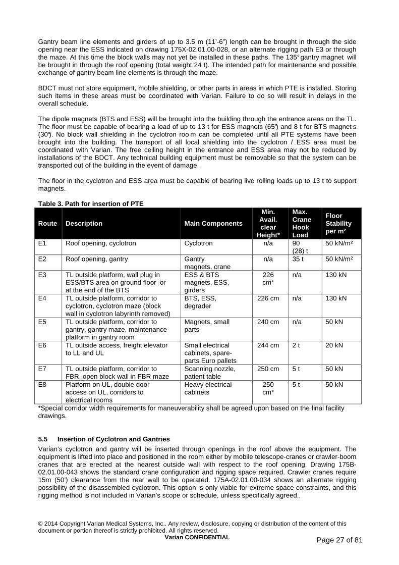
© 2014 Copyright Varian Medical Systems, Inc.. Any review, disclosure, copying or distribution of the content of this document or portion thereof is strictly prohibited. All rights reserved.
Varian CONFIDENTIAL Page 27 of 81
Gantry beam line elements and girders of up to 3.5 m (11’-6”) length can be brought in through the side opening near the ESS indicated on drawing 175X-02.01.00-028, or an alternate rigging path E3 or through the maze. At this time the block walls may not yet be installed in these paths. The 135° gantry magnet will be brought in through the roof opening (total weight 24 t). The intended path for maintenance and possible exchange of gantry beam line elements is through the maze. BDCT must not store equipment, mobile shielding, or other parts in areas in which PTE is installed. Storing such items in these areas must be coordinated with Varian. Failure to do so will result in delays in the overall schedule. The dipole magnets (BTS and ESS) will be brought into the building through the entrance areas on the TL. The floor must be capable of bearing a load of up to 13 t for ESS magnets (65°) and 8 t for BTS magnet s (30°). No block wall shielding in the cyclotron roo m can be completed until all PTE systems have been brought into the building. The transport of all local shielding into the cyclotron / ESS area must be coordinated with Varian. The free ceiling height in the entrance and ESS area may not be reduced by installations of the BDCT. Any technical building equipment must be removable so that the system can be transported out of the building in the event of damage. The floor in the cyclotron and ESS area must be capable of bearing live rolling loads up to 13 t to support magnets. Table 3. Path for insertion of PTE
Route Description Main Components
Min . Avail. clear
Height*
Max. Crane Hook Load
Floor Stability per m²
E1 Roof opening, cyclotron Cyclotron n/a 90 (28) t
50 kN/m²
E2 Roof opening, gantry Gantry magnets, crane
n/a 35 t 50 kN/m²
E3 TL outside platform, wall plug in ESS/BTS area on ground floor or at the end of the BTS
ESS & BTS magnets, ESS, girders
226 cm*
n/a 130 kN
E4 TL outside platform, corridor to cyclotron, cyclotron maze (block wall in cyclotron labyrinth removed)
BTS, ESS, degrader
226 cm n/a 130 kN
E5 TL outside platform, corridor to gantry, gantry maze, maintenance platform in gantry room
Magnets, small parts
240 cm n/a 50 kN
E6 TL outside access, freight elevator to LL and UL
Small electrical cabinets, spare-parts Euro pallets
244 cm 2 t 20 kN
E7 TL outside platform, corridor to FBR, open block wall in FBR maze
Scanning nozzle, patient table
250 cm 5 t 50 kN
E8 Platform on UL, double door access on UL, corridors to electrical rooms
Heavy electrical cabinets
250 cm*
5 t 50 kN
*Special corridor width requirements for maneuverability shall be agreed upon based on the final facility drawings.
5.5 Insertion of Cyclotron and Gantries Varian’s cyclotron and gantry will be inserted through openings in the roof above the equipment. The equipment is lifted into place and positioned in the room either by mobile telescope-cranes or crawler-boom cranes that are erected at the nearest outside wall with respect to the roof opening. Drawing 175B-02.01.00-043 shows the standard crane configuration and rigging space required. Crawler cranes require 15m (50’) clearance from the rear wall to be operated. 175A-02.01.00-034 shows an alternate rigging possibility of the disassembled cyclotron. This option is only viable for extreme space constraints, and this rigging method is not included in Varian’s scope or schedule, unless specifically agreed..

© 2014 Copyright Varian Medical Systems, Inc.. Any review, disclosure, copying or distribution of the content of this document or portion thereof is strictly prohibited. All rights reserved.
Varian CONFIDENTIAL Page 28 of 81
Assuming that the treatment level is at the same height as the outside ground level where the mobile crane is set up, Table 4 shows example configurations of mobile cranes that could be used to insert equipment into the building. Varian’s decision which type of crane to use will be project specific and depend on the local availability of cranes and access space. The area needed for crane setup and operation is not included in the required staging area in Table 2.
Figure 2. Alternative rigging crane for the Cyclotron
Under normal circumstances, roof openings are not used for maintenance. However, to provide means to deal with force majeure events such as earthquakes, the roof openings must remain accessible, and it must be possible to open them. No non-removable, permanent structure of the remaining building may be placed over the openings. Table 4. Examples of mobile cranes
Disassembled Cyclotron
Pre-assembled Cyclotron Standard Gantry
Heaviest hook load 28 t 90 t 35 t
Distance load – edge of building
13 m 13 m 16 m
Min. hook height above ground*
9 m + 5 m 9 m + 6 m 11 m + 5 m
Safety distance, crane to building
2 m 2 m 2 m
Half-width of crane base 5 m 6.5 m 5 m
Distance crane axis load 19 m 20.5 m 23 m
Type of crane 250 t – 300 t 800 t 300 t
Est. counterweight 65 t – 90 t 150 t 90 t
Reference 175A-02.10.00-034 *Highest building obstacle plus approximate height of load.
Temporary weather protection covers must be provided by the BDCT for rigging openings. The rigging openings for the cyclotron and gantries must remain covered by a temporary roof, guaranteeing protection from the weather and allowing for multiple openings and closings, especially due to changing adverse weather conditions. The temporary roof must be opened on each day of rigging and closed temporarily after the conclusion of work each day or in the event of precipitation. The design of the temporary roof must

© 2014 Copyright Varian Medical Systems, Inc.. Any review, disclosure, copying or distribution of the content of this document or portion thereof is strictly prohibited. All rights reserved.
Varian CONFIDENTIAL Page 29 of 81
allow to open or close the opening in less than 1 hour. Figure 3 shows an example of material that has been used very successfully for this purpose. A room temperature between 17°C (63°F) and 26°C (79°F) must also be maintained in the rooms with the temporary roof in place.
Figure 3. Standard insulated façade element with tongue and groove, usable for temporary roof
The roof openings can be closed permanently after the mechanical installation has been declared complete by Varian. The outside area must be suitable for the use of the chosen mobile crane. This places requirements on the access to the respective building site, ground stability, and size of the movement area. During the rigging process, other activities on the site may have to be limited. Varian and the BDCT will agree on acceptable conditions. It is then the BDCT’s responsibility to provide these in accordance with the agreed schedule. It is the responsibility of the BDCT to provide:
1. Appropriate ground stability on the customer’s property for special transport equipment and mobile cranes.
2. Appropriate ground smoothness on the customer’s property for special transport equipment. 3. Sufficient structural stability in the building for special rigging equipment (including the load)
positioned on top of the concrete shield. 4. Sufficient clearance above the rigging openings. 5. Access from the public road access to all rigging openings free of materials or other installations
(note: this may include installations on top of the roof, such as venting ducts). Details will be coordinated when the customer’s site and its conditions are known. BDCT must provide external cranes for civil work and internal cranes for rigging and maintenance as presented in Table 6.
5.6 Installation of Heavy Magnets in the BTS and ES S The 65° magnets (13 t) in the ESS will be transport ed into the building via E3 or E4. Special floor evenness requirements apply. There must be no steps or door sills between the platform on the outside of the building and the ESS. The floor must be smooth. The clear width of the installation path must be coordinated between Varian and the BDCT. While 210 cm (7’) wide clear straight paths are sufficient, corners and BDCT installations may require extra space. Floor requirements to be fulfilled by BDCT:
1. Smooth, polished, and sealed concrete floor or smooth synthetic resin–coated floor (probably shock resistant through additional glass fiber layer).
2. Evenness and waviness according to DIN 18202, part 5, line 4 (see 3. 4. 5. Table 5). 6. Surface roughness Ra: 6.3 µm–12.5 µm. 7. Expansion joints must be airtight, V-shaped gap. 8. Foot plates must be flush with finished floor for 65° dipoles and in between.

© 2014 Copyright Varian Medical Systems, Inc.. Any review, disclosure, copying or distribution of the content of this document or portion thereof is strictly prohibited. All rights reserved.
Varian CONFIDENTIAL Page 30 of 81
Table 5. Excerpt from DIN 18202 regarding evenness
Kind of Execution Evenness tolerance in [mm] depending points on the distance between the reference points
0.1 m 1 m 4 m 10 m 15 m Standard execution according to DIN 18202, part 5, line 3 2 4 10 12 15 Enhanced exactness according to DIN 18202 part 5, line 4 1 3 9 12 15 Leveled surface 1 3 6 6 6 Leveled surface with enhanced exactness 1 1 3 5 5
The BTS magnets (up to 8 t) will be transported into the building via E3 or E4 on standard trolleys and with the help of the I-beam installed at the ceiling in the BTS. The load onto the floor will be up to 5 t for each trolley, due to asymmetrical loading. Temporary trench cover reinforcement will be used during installation of the magnets at the respective location.
5.7 Installation of Devices in the Fixed Beam Rooms Rigging path E7 will be used. Devices up to 5 t in weight will be transported on a standard trolley via the open block wall in the FBR maze.
5.8 Installation of Large Electrical Cabinets The heaviest electrical cabinet is the high voltage power supply in the cyclotron electrical room. It has a weight of 4.5 t. The heaviest electrical cabinets in the magnet power supply room have a weight of up to 1.2 t. For all electrical cabinets there must be two façade openings to enter into the building, as indicated in drawings 175B-02.01.00-029, 175B-02.01.00-030 and 175B-02.01.00-042. On the ground level, in front of each façade opening the BDCT must provide a suitably stable and clean area. Inside each façade opening an I-beam with hoist must be provided to lift the cabinets and hoist them into the building. The rigging path must be wide enough and high enough to allow moving the cabinets with standard trolleys; the floor of the rigging path must be able to carry the respective load during rigging. Details must be agreed between BDCT and Varian based on the actual facility layout drawings. The clear width of the installation path must be coordinated between Varian and the BDCT. While 210 cm (7’) wide clear straight paths are sufficient, corners and BDCT installations may require extra space.
5.9 Permanently Installed Cranes in Building Required fixed cranes are listed in Table 6 below. More detailed specifications will be supplied during the project. All cranes must be electrically movable with electronically controlled hoists. Frequency drives and very slow speeds must be available. The hoist speed of the cyclotron crane must be reducible to 0.6 m/min. The gantry crane must be radio controlled; no cable control box shall be used for normal operation. The BDCT shall provide proposals that must be approved by Varian. Table 6. Permanent cranes and elevator to be instal led inside the building Location Designation Number Capacity Comment s Cyclotron Cyclotron bridge crane 1 1 t BTS I-beam with hoist 1 8 t Along BTS, manual hoist;
minimum hook height must be coordinated
Gantry room Gantry bridge crane 1 per gantry room 12.5 t near workshop freight elevator 1 2 t

© 2014 Copyright Varian Medical Systems, Inc.. Any review, disclosure, copying or distribution of the content of this document or portion thereof is strictly prohibited. All rights reserved.
Varian CONFIDENTIAL Page 31 of 81
5.10 Freight Elevator Requirements A freight elevator in the entrance area must be capable of bearing loads of up to 2000 kg (4500 lbs) and must offer sufficient space for a pallet truck and industrial pallets 120 cm x 120 cm (48” x 48”). A clear door width of 125 cm (50”) shall be considered the minimum. The elevator will be used regularly for maintenance purposes. The clear height to access the elevator must be 240 cm (7’-10.5”). The elevator must serve all rooms where PTE is installed without additional steps, and must be available for operation at RFE
5.11 Permanently Installed Maintenance Platforms BDCT is responsible for all permanently installed maintenance platforms, as listed below. All platforms must be planned and realized in coordination with Varian.
5.11.1 Cyclotron Platforms
Fixed platforms and stairs are required to cover the cyclotron pit and a 2nd level platform is required to maintain the cyclotron. BDCT is responsible for the detailed planning, design, and realization. The pit cover platform must be suitable for supporting 10 kN/m² and 20 kN in total, maximum. An opening must be provided in the staging floor of 140 cm (4’-7”) by 125 cm (4’-2”) to allow equipment to be lowered by the crane (hence this opening must be in the hook moving range of the crane). Stairs must lead down to the cyclotron pit. The platform must have a cutout around the cyclotron with a diameter of 320 cm. Further details will be provided during the construction phase. Details and more precise dimensions of the pit cover shall be taken from PT068778. Details for the cyclotron maintenance platform shall be taken from drawing 01-11-2-002. A structural (seismic) calculation is available on request.
5.11.2 Gantry Room Platforms
Gantry room platforms are: 1. Patient area platform to be adapted to the gantry contours. 2. Main maintenance platform. 3. Cable platform.
Components with a weight of up to 5 t will be brought into the gantry rooms. In order to lift these parts with the necessary bridge crane, the parts will be carted on the maintenance platform in the technical area. This platform will also serve as a maintenance platform with direct access to the gantry. Later, when the system is completed, part of this platform will form the floor of the treatment room, and the major part of the platform—the maintenance platform—will be in the technical area separated from the treatment area. The technical area will have two floor levels as a result of the platform. The lower level will be accessed by means of steel stairs. Gantry room platforms are steel constructions. Items 2 and 3 above must be fitted to the gantry room prior to gantry installation, and then removed. After gantry installation, welding or abrasive cutting on steel platforms is not allowed. Platforms in the gantry rooms are shown in drawing 175X-02.01.00-002, 175X-02.01.00-016, and 175X-30.08.06. BDCT is responsible for the detailed planning, design, and realization. The platforms must be planned and realized in coordination with Varian.
5.11.3 Fixed Beam Room Pit Cover
The pit and trench covers shown on drawing 175X.02.01.00-037 must be provided by the BDCT. The pit cover must satisfy the Varian Design Description, document 1870-DD-CO-0216.
5.11.4 Outside Platforms
For the rigging paths E3, E4, and E8, outside platforms are required to bear the respective load. Ground level platforms may be just a concrete slab large enough to place the respective equipment. For rigging paths E3 and E5 this platform must be at least 5 m x 5 m (15’ x 15’) with a load-bearing capacity of 13 t. The UL platform for E8 must be at least 3 m x 3 m (10’ x 10’) with a load-bearing capacity of 5 t. It must be reachable with the construction crane.

© 2014 Copyright Varian Medical Systems, Inc.. Any review, disclosure, copying or distribution of the content of this document or portion thereof is strictly prohibited. All rights reserved.
Varian CONFIDENTIAL Page 32 of 81
5.11.5 Other Platforms
The BDCT is also responsible for all other platforms—for example, the maintenance platforms for BDCT-installed equipment such as the gantry cranes.
5.12 Rigging Openings in Shielding Walls Table 3 defines the requirements for paths to bring various parts of the PTE into the building. For the purpose of describing rigging openings and paths, this document assumes that the TL is accessible from the outside at ground level. If this is not the case, appropriate changes will have to be coordinated between BDCT and Varian. The BTS vault has a block-wall opening for insertion of magnets and related BTS and ESS equipment (see drawing 175X-02.01.00-028). This opening can also be used for BDCT equipment or shielding elements. The opening must be access-restricted and thermally insulated. In addition, the cyclotron maze must have a removable section, as defined in drawing 175X-02.01.00-028. Wall openings connecting the BTS area with each treatment room shall be realized as shown in drawing 175X-02.01.00-028. These openings shall remain open until all equipment is installed and shall be closed by the BDCT according to an agreed schedule. Typically, an emergency exit from the BTS is required by local regulators. It may be an advantage to have the respective maze at the emergency exit built from removable concrete blocks in order to have an alternate rigging or maintenance access. Should the wall opening near the ESS, as shown on drawing 175X-02.01.00-028, not be available, this rigging opening is required. Gantries will be installed through a roof opening, as shown in drawing 175X-02.01.00-008. Installation of the doors to the radiation areas may have to be delayed until all equipment is installed. A detailed schedule must be agreed between Varian and the BDCT during the progress of the civil works. Closure of all roof and wall openings with prefabricated concrete blocks or slabs is the responsibility of BDCT. The roof openings must remain accessible to be opened in case of force majeure events. The BDCT must provide the following rigging openings in shielding walls:
1. Roof opening, cyclotron. 2. Roof opening, gantry. 3. Wall opening in cyclotron maze. 4. Wall opening in ESS wall or access via the end of the BTS tunnel. 5. Beam line feed-through between treatment rooms and BTS.
5.13 Doors to Non-Radiation Areas These doors are typically those to electrical rooms, control rooms, storage areas, and workshops. Equipment will be inserted via normal doors, façade doors on the TL and UL, and elevators installed in the building. Doors or wall openings up to the full ceiling height must be provided in many areas for transport into the building. Door sills create problems and delays for installation and must be avoided while heavy equipment is installed initially. This holds especially for the rigging paths E3 and E4. Outside access hatches or doors at the lower and upper level and adequate scaffolding must be provided by the BDCT during the installation period. The access doors must provide access for installation, service, and maintenance. All double doors in the electrical rooms must have a clearance height of at least 244 cm (8’) for operation and maintenance. Installation of the doors to the electrical rooms may have to be delayed until all equipment is installed. Some doors require larger vertical clearance for installation according to Table 3. A detailed schedule must be agreed between Varian and the BDCT during the progress of the civil engineering work to coordinate this. The clearance height of the transport path into the Varian electrical rooms must be optimized for the ceiling height of the technical rooms. A clearance height of 275 cm (9’) is

© 2014 Copyright Varian Medical Systems, Inc.. Any review, disclosure, copying or distribution of the content of this document or portion thereof is strictly prohibited. All rights reserved.
Varian CONFIDENTIAL Page 33 of 81
adequate for transport purposes. The double door from the workshop to the hall must have a clearance height of at least 244 cm (8’) (finished size) and a width of at least 226 cm (7’-5”) (unfinished size). All corridors used for installation of PTE must have a minimum clear, unobstructed width of 210 cm (7’). Equipment size places further constraints on the corridor width in front of electrical rooms and when the installation path turns around a bend. The BDCT must coordinate all corridors relevant to equipment installation and maintenance with Varian. The doors to the treatment control rooms must have a clearance height of at least 220 cm (7’-4.5”), and the door to the main control room must have a clearance height of at least 244 cm (8’) (finished sizes). During the building design phase, the door and wall opening requirements will be defined together with the BDCT in order to reach standard dimensions according to local building codes.
5.14 Doors to Radiation Areas These doors provide access to controlled radiation areas and/or separate zones inside radiation areas. Examples are doors to and inside treatment rooms; access to the cyclotron, ESS, and BTS; access to the cyclotron pit; and access to BTS zones. Special requirements may apply to the access doors to radiation areas. In particular, these requirements deal with the locks, closing systems, air seal, and stability of the doors. Sensory devices provided by Varian will need to be installed by the BDCT inside doors and frames. BDCT must incorporate these special requirements into the doors. Conduits must be provided inside the concrete for all signal cable to the doors. The conduits shall lead to the nearest treatment control room’s suspended ceiling. Varian will integrate these sensors into the control system for the equipment, and BDCT will integrate them in the security system for radioprotection. Shielding doors, should they be required, are in the scope of supply for BDCT.
5.15 Structural Requirements for Walls and Floors L oads
5.15.1 Cyclotron Room
The feet of the cyclotron must rest on steel floor plates. The floor plates must be delivered and installed by the BDCT on the pit floor slab and then cemented into place. The load is 40 t per foot. The steel plate must be positioned with high precision by the BDCT. Varian reserves the right to verify the exact positions prior to the cementing of the foot plates. See section 4.1.1. Further Varian requires embedded plates in the cyclotron pit walls. Details and more precise dimensions for the base plates and required embedded plates in the cyclotron pit walls shall be taken from PT06913200. Details on the platform for the cyclotron pit can be found in section 5.11.1.
5.15.2 ESS and BTS
The dipole magnets of the BTS and the ESS represent a load of 8 t and 13 t, respectively, on the floor. Dipoles are mounted on steel plates that are mounted on the concrete floor and aligned using precision instruments before the floor finishing is applied . Girders with quadrupole and steering magnets, as well as beam diagnostics are mounted on steel base plates that are mounted onto the floor. Drawing PT068881 specifies the base plates for the ESS and BTS beam line modules. These plates must be installed by the BDCT with a lateral accuracy given in section 4.2. Drawing PT068881 shows an example layout. Attention is drawn to detail C and D in this drawing. The base plates in detail C and D must be installed flush with the finished floor level; all other foot plates will be above finished floor level. Figure 5 shows an example for BTS foot plates. The precise layout and quantity for each plate will be given to the BDCT once the beam line configuration has been finalized.

© 2014 Copyright Varian Medical Systems, Inc.. Any review, disclosure, copying or distribution of the content of this document or portion thereof is strictly prohibited. All rights reserved.
Varian CONFIDENTIAL Page 34 of 81
The BDCT is responsible for anchoring the plates, appropriate to the earthquake zoning of the facility. The center of gravity may be assumed to be at 125 cm (49”) above the finished floor.
5.15.3 Gantry Room
The feet of the gantry will apply a total load of 280 t at four locations. The floor of the gantry rooms (approx. 383 cm (12’-7”) below treatment floor level) must be capable of bearing lumped loads of up to 50 kN for maintenance work on the 135° magnet. A load-bearing capacity of up to 5 t must be guaranteed for the area from the gantry mazes to the entrance for transport. One recess is required in each gantry room floor to provide clearance for the 135° dipole when it pass es through the 180° gantry position. This is illustrat ed in drawing 175X-02.01.00-035. The platforms and maintenance catwalks must support equipment up to 2 t. Occasionally the platforms may have to support 5 t weights. For this purpose, steel plates and extra support columns shall be used to distribute and maintain the load appropriately.
5.15.4 Access Floors and Trench Systems
Access floors and trench systems must be used for cable trays, cable connections, and cooling water connections. All access floors and trench cover plates in the PTE area must have an overall load-bearing capacity of 7.5–10 kN/m², unless otherwise specified. For all cabinets, a frame must be supplied to bear the weight of the cabinets and provide access to the double floor below. The heaviest cabinets weigh up to 4.5 t. A detailed layout of all frames with specifications for their respective load-bearing capacity must be proposed by the BDCT and coordinated between the BDCT and Varian. Access floor is defined as fully removable floor panels, typically 60 cm x 60 cm (2’ x 2’), that are supported on a structure of feet and beams. Figure 4 shows a typical access floor with frames for electrical cabinets that fulfills the requirements. The installation density underneath the access floor is very high. Extreme care must be taken in planning for collision avoidance between access floor feet, cable trays, and piping.
Figure 4. Typical access floor The cable trench cover in the ESS and BTS must have a load-bearing capacity of 7.5–10 kN/m². The media trench in the BTS must have a load-bearing capacity of 7.5–10 kN. Floor drains must be included in all electrical supply rooms, and especially in the access floor and trenches. Floor drains must be in all trenches in the ESS and BTS, as well as in the cyclotron pit. Floor drains must be connected to the building sewer system. Floor drains from the cyclotron area, ESS, BTS, and treatment rooms may need to be connected to a hold-reservoir prior to drainage into the city sewer to allow for radioactivity testing. The BDCT is responsible for maintaining the building drainage system at all times. Table 7 lists the rooms requiring access floors or trench systems to be realized by BDCT, and summarizes their dimensional requirements by room. Wall feed-throughs must be in the respective access floors. BDCT must coordinate the exact planning of the access floors with Varian. Cable trays must be provided and installed by BDCT from the power hookup points into the access floor and in the access floors in accordance with Varian’s specifications. Detailed specifications will be provided. Preliminary data to estimate the number and size of cable trays are shown in drawings 175X-02.01.00-033,

© 2014 Copyright Varian Medical Systems, Inc.. Any review, disclosure, copying or distribution of the content of this document or portion thereof is strictly prohibited. All rights reserved.
Varian CONFIDENTIAL Page 35 of 81
175X-02.01.00-025 or 175B-02.01.00-025, and 175X-02.01.00-001 or 175X.02.01.00-001, depending on building configuration. Table 7. Double floor and trench systems Room Access Floor Trench System Max. Weight
Cyclotron electrical room See dwg 175A-30.08.08 or 175B-30.08.08
min 60 cm (24”) deep
max 110 cm (4’-4”) deep
RF-amplifier: 4.5 t
Technical gases See dwg 175A-02.01.00-023 or 175B-02.01.00-023
Diagnostic room See dwg 175X-30.08.02 or 175B-30.08.02
100 cm (40”) deep
Magnet power supply room See dwg 175X-30.08.02 or 175B-30.08.02
100 cm (40”) deep
135° PS: 2.4 t
ESS/BTS n/a See drawings
175X-02.01.00-028 and 175X-30.07.16
65° dipole: 13 t
30° dipole: 8 t
quad: 600 kg
Main control room See section 4.6.1
Treatment control room See section 4.6.2 Requirements to be fulfilled by BDCT:
1. Access floors and trench systems must be provided according to Table 7 and respective drawings. Frames for cabinets, cable tray layout, and support structure for the access floor must be coordinated with Varian.
2. During Varian’s installation access floor plates must be removed. All access floor plates must be available for re-installation after Varian’s installation is complete.
3. All access floors and trench covers must have a load-bearing capacity of 10 kN/m², unless otherwise specified on respective BID drawings.
4. All electrical cooling water connections must be in the access floors and cable trenches. 5. All access floors and trenches must have floor drains. The floor drains in all electrical rooms must
be connected to the building sewer system. Water collected in the floor drains in the ESS/BTS area may be considered controlled waste, depending on the local radiation regulatory bodies.
6. Underneath all access floors and in all trenches, walls and floors must be painted with a water proof and dust repellent finish.
7. Cable trays must have a clearance of 10-15cm on one side along the length of the tray 8. Cable trays must not obstruct floor drains, conduits and must not collide with IF locations 9. water pipes, also the ones for our IF must always be below all cable trays 10. IF must be reachable through the access floor by removing only one access floor plate per IF,
valves must be close enough to the access floor to allow operation without removing handles (hence not too close)
11. Lighting fixtures location and size must be coordinated with all information available. 12. Access floor feet must not collide with cable trays or reduce clearance (see above) 13. Conduits in walls must not be obstructed by cabinet stands or access floor feet or any other
equipment Varian is aware that it may not be possible to position every single conduit exactly per the BID requirement. Therefore in planning the conduit locations, the following tolerances should be used:
1. Conduits in MPSR: parallel to the cabinets 15cm (+/-6”), perpendicular to the cabinets within 10cm (4”)

© 2014 Copyright Varian Medical Systems, Inc.. Any review, disclosure, copying or distribution of the content of this document or portion thereof is strictly prohibited. All rights reserved.
Varian CONFIDENTIAL Page 36 of 81
2. Cable trays: +/-15cm( 6”) 3. Cabinet stand locations: better than 1cm (1/2”) 4. Dimensioned MEP locations in 175B-02.01.0-025 and 001: within 10cm (4”) 5. Conduits in 175X-02.01.00-038: within 10cm laterally, as close as possible to trench top (not lower
than 10cm).
5.15.5 Surrounding Areas
Ground stability to install mobile cranes of up to 800 t for rigging of the heavy components must be provided by the customer in the vicinity of the outside walls of the respective equipment room and close to the entrance to the workshop. The transport openings into the TL and UL must be accessible for the mobile crane and flatbed trailers. The exact requirements for the outside areas require further definition, based on site conditions. A concept must be coordinated and agreed between Varian and BDCT. Platforms must be made available in the TL entrance areas and must be capable of bearing loads of up to 130 kN.. Sills and grooves and small steps of any kind must be avoided for transport into the building. Insertion of the power supplies into the upper level will be done via the doors in the façade of the upper level. During the installation period, Varian requires a temporary platform in front of the façade doors with a load-bearing capacity of 50 kN. The platform must allow level entrance into the building on the upper level. The use of construction cranes is required to lift heavy power supplies onto the platform. Should normal construction cranes not be available on site, Varian will arrange appropriate mobile cranes.
5.16 Specific Structural Stability Requirements Several elements must be cast into concrete walls, floors, and ceilings that will be used for maintenance and installation purposes. These include Halfen rails (unistruts), installation connection plates, and steel plates that can bear loads and shear forces.
5.16.1 Load Supporting Embedded Objects
Load supporting base plates are needed as an interface between heavy equipment and the building. These plates also serve as reference positions to adjust PTE-feet. The positioning and fixation of these base plates demand special attention, and tolerance requirements exceed normal civil construction limits. Brackets and preferably Halfen rails (unistruts) for the lighter loads must be embedded into the walls and ceilings to serve as mounting points, as specified in

© 2014 Copyright Varian Medical Systems, Inc.. Any review, disclosure, copying or distribution of the content of this document or portion thereof is strictly prohibited. All rights reserved.
Varian CONFIDENTIAL Page 37 of 81
Table 8. Beamline base plates are shown in drawing P068881. Requirements to be fulfilled by BDCT:
1. Install all base plates for magnets and gantries. 2. Deliver and install foot plates for the cyclotron. 3. The installation of all embed and base plates must be realized with a lateral accuracy for all edges
of ±10 mm (1/2”), a vertical accuracy of ±5 mm (1/4”), and a maximum tilt of 2 mm (5/64”) over the respective plate. The position accuracy must be related to the building reference system.
4. Base plates must be installed in the concrete using suitable anchors for load and shear forces for normal use and during earthquakes. For shear force calculations, the BDCT must assume that the center of gravity is at the center of the cyclotron and that the cyclotron has a weight of 120 metric tons.
5. Prior to grouting, the BDCT must verify the alignment of the plates and receive approval from Varian.
6. After grouting, all plates are required to have level surfaces. Bolts extending through the surface have to be cut. Bolts extending through the surface have to be removed or cut off so as not to impair the level surface.

© 2014 Copyright Varian Medical Systems, Inc.. Any review, disclosure, copying or distribution of the content of this document or portion thereof is strictly prohibited. All rights reserved.
Varian CONFIDENTIAL Page 38 of 81
Table 8. BDCT-supplied load supporting embedded obj ects ID Description Quantity, Load
Factors Reference
Cyclotron Room Base plates, cyclotron 3, support 40 t each P06913200
Halfen rails (unistruts) in RF feed-through to
cyclotron electrical room Every 80–100 cm (30”–40”), vertical
175A-30.08.04 175B-30.08.04
wall plates in cyclotron pit wall P06913200 Recommended: wall embed plates for 2nd level
platform supplied by BDCT 11x 01-11-2-002
Degrader, ESS, BTS Base plates for beamline modules,
qty is project specific. According to project layout
PT068881
Trench support structure for 30° dipole For each t reatment room
PT06888100 item L
Halfen rails (unistruts) in cable feed-throughs - 1st treatment room to ESS - treatment room to BTS
Every feed-through, every 80–100 cm (30”–40”), vertical
175X-30.07.16
Halfen rails (unistruts) in ceiling above degrader / ESS
100 cm (40”) long, 100 cm (40”) distance
175X-30.07.20
Halfen rails (unistruts), ceiling BTS Complete BTS, distance ca. 100 cm (40”)
175X-30.07.20
Embedded plates above the 65° dipole magnets
6x point load of 6t
SK-3215-05R0
Embedded plates above 30° dipole magnets 7x point load of 6t for each branch
SK-3215-08R0
Each Gantry Room Base plates in floor 2 each
in gantry room 175X-02.01.00-035
Crane consoles 2 each Halfen rails (unistruts) in feed-through See drawing
175X-02.01.00-032
patient table support see drawing 175X-02.01.00-035 Each Fixed Beam Room Quadrupole base plates 3 PT06888100 Patient table support plates, 7288-107004
5.16.2 Embedded Cooling Water and Technical Gas Pipes
Water pipes need to be embedded in the concrete to provide cooling water in all electrical rooms, the cyclotron pit, treatment rooms and the beam line area. The following requirements:
1. The pipes must be encased in a vibration damping and thermal insulating material. 2. The pipes must be protected from direct contact with concrete in order to prevent corrosion. 3. Large-radius elbows and bends must be the preferred construction method used. 4. Any water or gas pipe or duct embedded in concrete (such as technical compressed air, room air
supply and exhaust, etc.) must be encased in vibration damping material. A sample list for required interface points for cooling water, compressed air and other technical gases can be found in the appendix. A project specific list will be provided during the building design phase. Varian will also provide a project specific drawing for interface point connections in the TL.

© 2014 Copyright Varian Medical Systems, Inc.. Any review, disclosure, copying or distribution of the content of this document or portion thereof is strictly prohibited. All rights reserved.
Varian CONFIDENTIAL Page 39 of 81
5.16.3 Conduits
A sample conduit list can be found in the appendix. A project specific conduit list will be provided during the building design phase. Most conduits must be embedded into concrete walls. The minimum radius for any bend of a conduit is defined similar to NEC, but may deviate in some cases. The standard minimum conduit radius for any bend is given in Table 9. Varian will highlight any conduit that needs a larger bend radius as indicated in Table 9. For these exceptions Varian requires a minimum bend radius of 50cm (20”). These exceptions include, but are not limited to the following:
1. Conduits not intended for electrical cables (e.g. helium, oxygen, hydrogen, vacuum, nitrogen, cooling water, etc.)
2. Conduits intended for radio-frequency cables, especially very ridged coax cables. 3. Conduits C10M01 and C10M02 (see 175X-02.01.00-038). These conduits must not have any
bends and be in a straight line, positioned within 5cm (2”) of their position shown on drawing 175X-02.01.00-038.
Table 9. Minimum Radius of Conduits according to NE C Conduit Size Minimum Bend Radius Preferred Bed radius
metric US trade size
mm in . mm in.
16 1/2 101.6 4 102 4 21 3/4 114.3 4 ½ 127 5 27 1 146 5 ¾ 152 6 35 1 1/4 184 7 ¼ 203 8 41 1 1/2 209 8 ¼ 254 10 53 2 241 9 ½ 305 12 63 2 ½ 267 10 ½ 381 15 78 3 330 13 457 18 91 3 1/2 381 15 533 21 103 4 406 16 610 24 155 6 762 30 914 36
The following requirements apply:
1. All embedded conduit ends must be flush at walls and have a smooth edge. Rough surfaces must be avoided as they might damage the cables during the rigging activities.
2. A maximum of 4 bends is allowed 3. Conduits embedded inside radiation shielding wall typically need a minimum of 2-3 bends. This
shall be determined by the BDCT’s radiation expert. 4. Minimum bend radius for all conduits must be maintained. In some cases the bend radius must be
larger than given in Table 9. These conduits are listed in the exceptions above. 5. BDCT meets the relevant articles of Chapter 3 of the NEC (or NFPA 70) on “Bends – How Made”
as device in 3xx.24; “Bends – Number in One Run” as defined in 3xx.36 and referring to Table 9. 6. The inside surface of conduits must be even, with pull cable installed. 7. When conduits exit the concrete from the floor in areas where water might be present (trenches,
access floors), the conduits must be stubbed and extended by 10cm (4”) 8. Conduits lengths shall be minimized 9. The BDCT shall provide to Varian an as-built list that confirms the actual length of every conduits in
the project specific conduit list. Varian requires that specific media pipes and conduits be embedded in the concrete, and that the interface points are positioned very accurately.

© 2014 Copyright Varian Medical Systems, Inc.. Any review, disclosure, copying or distribution of the content of this document or portion thereof is strictly prohibited. All rights reserved.
Varian CONFIDENTIAL Page 40 of 81
Table 10 lists references to drawings describing the location of the respective conduits and interface points. Exact routing shall be proposed by the BDCT.

© 2014 Copyright Varian Medical Systems, Inc.. Any review, disclosure, copying or distribution of the content of this document or portion thereof is strictly prohibited. All rights reserved.
Varian CONFIDENTIAL Page 41 of 81
Table 10. Cross-reference of conduit and interface points in lists with BID drawings ID From To Comment Reference 1 Cyclotron area Technical gases
room all conduits must have 50cm bending radius
175X-02.01.00-025, 175B-02.01.00-025 175A-02.01.00-023 175B-02.01.00-023
2 Cyclotron area Cyclotron electrical room
175A-30.08.08 175B-30.08.08
3 Cyclotron area BDCT-defined, multiple locations
Nitrogen supply Compressed air supply Cooling water (supply & return, spare) Vacuum exhaust Quench exhaust Exhaust ventilation Oxygen supply & spare
175X-02.01.00-025, 175B-02.01.00-025 section 8 through 10
4 Cyclotron electrical room
175A-30.08.08,
5 Cyclotron area Main control room 175X-02.01.00-025, 175B-02.01.00-025 175X-02.01.00-015
6 Treatment control room
Gantry Treatment room, patient table pit
175X-02.01.00-014 175X-02.01.00-001 175B-02.01.00-001
7 Treatment control room
Gantry Treatment room, patient area above suspended ceiling
175X-02.01.00-014 175X-02.01.00-001 175B-02.01.00-001
8 Diagnostic room 175X-30.08.02 175B-30.08.02 175B-02.01.00-048
9 Treatment control room
Fixed Beam Treatment room, patient table pit
175X-02.01.00-014 175X-02.01.00-049
10 Treatment control room
Fixed Beam Treatment room, patient area above suspended ceiling
175X-02.01.00-014 175X-02.01.00-049
11 BTS media trench
BDCT-defined Cooling water supply and return for ESS and BTS Compressed air supply
175X-02.01.00-036
12 BTS cable trench
each treatment room 175X-02.01.00-001 175B-02.01.00-001
13 BDCT-defined Each treatment room Compressed air supply Cooling water supply and return
14 BTS Each treatment room Alignment structure 175X-02.01.00-041 15 ESS cable
trench ESS cable trench precision of installation:
within 5cm (2”) 175X-02.01.00-038
.

© 2014 Copyright Varian Medical Systems, Inc.. Any review, disclosure, copying or distribution of the content of this document or portion thereof is strictly prohibited. All rights reserved.
Varian CONFIDENTIAL Page 42 of 81
6 Building Tolerances and Equipment Alignment The building section in which the cyclotron, ESS, BTS, and all treatment rooms are installed must be built as one rigid structure. Expansion joints or separate floor slabs are not accepted. All treatment room floors must be an integral part of the concrete wall structures. This is to guarantee that building settlement will not lead to relative movement of individual PTE building sections with respect to each other. All floor levels indicated in the BID drawings or referenced in this document refer to finished floor heights, unless specifically noted otherwise. Especially in the treatment areas this means that all type of floor surface materials (e.g. vinyl, carpet, tiles, coatings, etc) must have their finished surface at the respective floor level given in the drawings. For convention only, Level 0.0cm is considered the finished floor on the treatment level.
6.1 Building Settlement Specific requirements will apply to the maximum differential settling of the building for the operation of the PTE after the installation and alignment of the PTE. The examination of the settling characteristics must be started during the construction of the building shell. The differential settling over a length of 10 m must be < 0.2 mm (0.008”)/year. It is the BDCT’s responsibility to design the building to the settlement requirements and to monitor building settlement rate before PTE is delivered. Varian assumes no liability for damages and system downtime resulting from the settling of the building.
6.2 Civil Engineering and Construction Tolerances Building tolerances must comply with DN 18202. Only standard tolerances according to DN 18202 are required, enhanced exactness is normally not required. If special tolerance requirements apply, they will be referred to as necessary in the BID drawings or in this document. The cyclotron pit and the cyclotron walls must be realized with a tolerance of +/- 1 cm (1/2”) with respect to the cyclotron center. Drawing 175X-02.01.00-025 or 175B-02.01.00-025 specifies the dimensions and locations. The evenness of the floor in the cyclotron area must fulfill the requirements of DIN 18202, whereby gradients can be included for drainage purposes. If no tolerances are indicated, DIN 18202, section 4 must apply analogously. Note: On request, DIN 18202 may be provided to the BDCT and explained by Varian.
6.3 Vibration Effects Vibrations have a direct effect on the quality of a proton therapy system. For this reason, there are strict requirements for the quality of the individual structural components, and especially for the interaction of the entire structure and the technical building equipment. Resonances of individual systems and amplification factors must be taken into account. Potential sources of concern are nearby railroad tracks, subways, highways, and truck traffic. During normal operation of the PT-system, vibrations of the building must be limited to those of laboratory type buildings as described by IES-RP-CC012.1, class A. For all frequencies not stated in this report, a maximum vibration velocity of 100 µm/s must not be exceeded.
6.4 Building Initial Geodetic Survey
6.4.1 Pre-alignment
The BDCT must provide access to all shielded areas to Varian four months prior to RFE, so that Varian can have unobstructed views (of shoring or materials) in order to establish a reference coordinate system. Varian will determine this reference coordinate system based on construction tolerances as-built in order to optimize the equipment installation. The ideal beam line height is 125 cm (49.21”) above the finished floor in ESS, BTS, and treatment rooms. Varian will provide a reference line on all walls and floor indicating the

© 2014 Copyright Varian Medical Systems, Inc.. Any review, disclosure, copying or distribution of the content of this document or portion thereof is strictly prohibited. All rights reserved.
Varian CONFIDENTIAL Page 43 of 81
ideal beam line height with an accuracy of 1–2 mm (0.04–0.08”) and base plate positions before the next steps described below. ESS, BTS, and fixed beam magnets will be placed on steel plates that have been installed by the BDCT shortly after civil work has been finished, based on the Varian established markings on the floor. The foot plates shall be installed by the BDCT with the precision given in section 4.2. These steel plates are backfilled by the BDCT with expanding concrete. Prior to backfilling, the BDCT will provide a geodetic survey report demonstrating the actual position of each foot plate within the building’s coordinate system. Backfilling occurs after Varian approval of the actual positions. The final flooring is poured and adjusted to the plates.
Figure 5. Steel mounting plates for magnets
The geodetic survey can be accomplished by a local measurement office and shall be precise to 1–2 mm (0.04–0.08”). The beam line position must be marked by the BDCT on the plates with a precision of 1–2 mm, so that the installation team in a first adjusting step could adjust the components by means of lead plumb and leveling instruments. Requirements:
1. The BDCT shall deliver and install the steel mounting plates according to Varian specifications. 2. The BDCT shall provide the geodetic survey and require approval from Varian prior to backfilling
the foot plates.
6.4.2 Reference Network
A high-precision reference coordinate system will be established by Varian. In order to do this, the building must be climatically stabilized. Ideally all HVAC equipment is operational. As airflow currents degrade the measurement precision, the HVAC equipment may have to be temporarily turned off during the measurements. A laser tracker system is used, with spherically mounted reflectors (SMRs). SMR bases are positioned on walls at different heights, as well as into the floor.
Figure 6. Ball mounting assemblies for permanent installation; center and right also show
an SMR (triple mirror) Varian will install all wall and ceiling mounted SMR bases. Thirty (30) floor bases are required in BTS, ESS, and fixed beam rooms. The SMR floor base will be provided by Varian.

© 2014 Copyright Varian Medical Systems, Inc.. Any review, disclosure, copying or distribution of the content of this document or portion thereof is strictly prohibited. All rights reserved.
Varian CONFIDENTIAL Page 44 of 81
Floor bases require holes be drilled into the finished floor by the BDCT prior to the final coating, at locations to be specified by Varian after the initial alignment review. Varian will place the SMR base into the BDCT-provided holes (as shown in Figure 7) and backfill it with 2-component epoxy. The BDCT must subsequently finish the floor coating such that the SMR floor base is integrated flush into the floor.
Figure 7. Installation of SMR floor base
Requirements to be fulfilled by BDCT:
1. Installation of all floor-mounted SMR bases according to Varian specifications. The final floor finish must be flush with the cover of the SMR base cover.
2. Support to rent mobile scaffolds or mobile scissor lifts must be provided by the BDCT.
6.4.3 RFE Requirements
Beginning with the establishment of the reference network, very strict dust, humidity, and temperature requirements must be adhered to during the alignment process. No turbulences shall exist, and temperature gradients shall be kept to a minimum. Please refer to section 5.2.1
6.4.4 Alignment Tubes
The BDCT must provide a special steel tube assembly to be embedded into the concrete for each treatment room, based on Varian’s specification. This assembly allows relating the alignment measurements from the BTS into the respective treatment room. Drawing 175X-02.01.00-041 shows the required tube assembly and its position in the concrete walls. The BDCT shall embed these assemblies into the walls between each treatment room and BTS.

© 2014 Copyright Varian Medical Systems, Inc.. Any review, disclosure, copying or distribution of the content of this document or portion thereof is strictly prohibited. All rights reserved.
Varian CONFIDENTIAL Page 45 of 81
7 Electrical System Requirements The BDCT is responsible for the installation and provision of the low voltage electrical power supply and emergency backup power units. Compliance with the power quality limits in EN 61000-2-2 in its most recent edition is required (see Table 12). Should other parts of EN 61000 that are valid at the time of RFE have more stringent requirements, then the more stringent requirements from other parts shall apply. The limit values of harmonic voltages at the respective hook-up points must be respected (see Table 11). Table 11. Limit values of individual harmonic volta ges at the hook-up points as percentage of U n
Odd Harmonics Even Harmonics Not Multiples of 3 Multiples of 3
Order Relative Voltage (%)
Order Relative Voltage (%)
Order Relative Voltage (%)
5 6 3 5 2 2 7 5 9 1.5 4 1 11 3.5 15 0.5 6….24 0.5 13 3 21 0.5 17 2 19 1.5 23 1.5 25 1.5
Table 12. Typical EN 61000 requirements on power qu ality No. Parameter Supply Voltage Characteristics
According to EN 50160:2008-04 Supply Voltage Characteristics According to EMC Standard EN 61000 EN 61000-2-2:2002 Other Parts, typical
1 Power frequency 50 Hz or 60 Hz, depending on local standard
LV W: mean value of fundamental measured over 10 s ±1% for 99.5% of week ±6% for 100% of week
2%
2 Voltage magnitude variations
LV, MV: ±10% for 95% of week, mean 10 minutes rms values
±10% applied for 15 minutes
3 Rapid voltage changes
LV: 5% normal, 10% infrequently Pit ≤ 1 for 95% of week MV: 4% normal, 6% infrequently Pit ≤ 1 for 95% of week
3% normal 8% infrequently Pst < 1.0 Pit < 0.8
3% normal, 4% maximum Pst < 1.0, Pit < 0.65 (EN 61000-3-3) 3% (IEC 61000-2-12)
4 Supply voltage dips Majority: duration < 1 s, depth < 60% Locally limited dips caused by load switching on: LV: 10–50%, MV: 10–15%
urban: 1–4 months
up to 30% for 10 ms up to 60% for 100 ms (EN 61000-6-1, 6-2) up to 60% for 1000 ms (EN 61000-6-2)
5 Short interruptions of supply voltage
LV, MV: (up to 3 minutes) few tens – few hundreds / year Duration 70% of them < 1 s
95% reduction for 5 s (EN 61000-6-1. 6-2)
6 Long interruption of supply voltage
LV, MV: (longer than 3 minutes) < 10–50 / year
7 Temporary, power frequency overvoltages
LV: < 1.5 kV rms MV: 1.7 Uc (solid or impedance earth) 2.0 Uc (unearthed or resonant earth)
8 Transient overvoltages
LV: generally < 6 kV Occasionally higher; rise time: ms – µs MV: not defined
±2 kV line-to-earth ±1 W line-to-line 1.2/50(8/20) Tr/Th µs (EN 61000-6-1, 6-2)
9 Supply voltage unbalance
LV, MV: up to 2% for 95% of week Mean, 10 minutes rms values, up to 3% in some locations
2% 2% (IEC 61000-2-12)

© 2014 Copyright Varian Medical Systems, Inc.. Any review, disclosure, copying or distribution of the content of this document or portion thereof is strictly prohibited. All rights reserved.
Varian CONFIDENTIAL Page 46 of 81
No. Parameter Supply Voltage Characteristics According to EN 50160:2008-04
Supply Voltage Characteristics According to EMC Standard EN 61000
10 Harmonic voltage 6%-5th, 5%-7th, 3.5%-11th, 3%-13th. THD < 8%
5%-3rd, 6%-5th, 5%-7th, 1.5%-9th, 3.5%-11th, 3%-13th, 0.3%-15th, 2%-17th (EN 61000-3-2)
11 Interharmonic voltage
LV, MV: under consideration 0.2%
Two options are available for Voltage and line frequency pairs: 400VAC at 50 Hz, or 480 VAC at 60Hz. Voltage and line frequency will be agreed upon at contract signature, and will be selected based on the locally available line frequency.
7.1 Connected Load For single gantry operation the electrical load drawn by PTE will be 850 kW at 250 MeV proton beam energy. Fast switching between gantry rooms requires that during a period of 5–10 seconds, magnets on both gantries are ramped respectively. For this short period the peak power increases up to 1500–1800 kW, depending on room configurations. The connected load (e.g., the dimensioning of transformers, bus bars, and compensation systems) must take into account the peak power during switching of gantries, hence the dynamic simultaneous operation of two gantries. Therefore, the connected load is based on the following assumptions:
• Fast ramping for ESS and switching dipoles is necessary. • Not all devices will be run at full capacity at the same time. The calculation includes an optimized
assumption of possible simultaneous loads. • The scope of the facility consists of one cyclotron, multiple gantries, and fixed beam rooms. • Neither facility cooling water generation, nor cooling water distribution, nor air conditioning is
considered in this power balance. The following power consumption, including safety margins, must be provided by the BDCT for installation, startup, normal operation, and maintenance operation: Connected mains load PTE total (nominal): < 1800 kVA Plus UPS power requirement: < 170 kVA For the purpose of connected load evaluation, gantry and inclined fixed beam rooms are equivalent. Emergency power by generator is recommended. The installation of a generator would substantially improve re-start time after a prolonged power outage. Details on emergency and UPS power are provided in section 7.5.
7.2 Connection Points The BDCT must design project specific documents and provide cabling of all power to the respective panel boards and cabinets of Varian. Examples for connection points are given in section 7.2.1 or 7.2.2, depending on the location. Connection points in the workshops must be defined by the BDCT and coordinated with Varian. BDCT must provide a sub-distribution system, connection points for machinery (3-phase), and wall outlets. Double wall outlets must be provided on the walls in 2.5 m (8’) intervals in all rooms where PTE is installed. Wall outlets must be provided according to local electricity standards. Magnet power supplies are supplied via a 3000A five-conductor plug-in bus way. The upper right hand corner of Figure 8 shows a typical plug-in bus way. Table 13 shows an example of the plug-in units and their required electrical data. A project specific list will be supplied to replace this example. Drawing 175B-30.08.02 provides information on how the plug-in units shall be distributed over the bus way.

© 2014 Copyright Varian Medical Systems, Inc.. Any review, disclosure, copying or distribution of the content of this document or portion thereof is strictly prohibited. All rights reserved.
Varian CONFIDENTIAL Page 47 of 81
Figure 8. Typical 5-conductor plug-in bus way
Drawing 175B-30.08.02, 175X-02.01.00-044 show the control cabinet layout for the ESS power supply room and the Magnet power supply room for building configuration B. While the exact layout of the cabinets will depend on local, site specific conditions, drawings 175B-30.08.02 and 175B-02.01.00-044 define the number and approximate location for all terminal boxes that must be supplied by the BDCT for the 5-conductor bus way. This bus way has to extend into all rooms where magnet power supplies are installed. In the USA, it is permissible for the BDCT to use additional connection boxes on the bus way to supply the 208 VAC network for PTE use. The total connected load would in this case be identical for the USA and Europe. The connection boxes on the bus way and cable trays or conduits leading from the bus way into the access floor must be installed by RFE. Please note that the typical connected loads for individual sub-distribution connection points may be larger than the total connected load, due to the assumption that multiple systems will be running simultaneously. The connected loads of the individual sub-distribution systems can be found in Table 14 and Table 15 below. All wall feed-throughs, including those requested by Varian, must be closed in accordance with the fire safety regulations (e.g., fire stops) by BDCT after installation is completed.

© 2014 Copyright Varian Medical Systems, Inc.. Any review, disclosure, copying or distribution of the content of this document or portion thereof is strictly prohibited. All rights reserved.
Varian CONFIDENTIAL Page 48 of 81
Table 13. Example of electrical connection data of plug-in bus way.

© 2014 Copyright Varian Medical Systems, Inc.. Any review, disclosure, copying or distribution of the content of this document or portion thereof is strictly prohibited. All rights reserved.
Varian CONFIDENTIAL Page 49 of 81
7.2.1 Europe (or other 50Hz environments)
Three phases, neutral, ground with 400 V mains voltage must be provided. The entire power must be provided over a fast acting cos φ compensation system, with filters for harmonics. The BDCT will provide a 400 VAC bus bar (5-conductor plug-in bus way) with hook-up points for the PTE in the relevant electrical rooms. Varian will install sub-distribution networks in the electrical rooms that must be connected to the main low voltage network by BDCT.
Table 14. 50 Hz: Connected electrical load hook-up points according to room Room Nominal
Connected Load 3 phase + N + G
(kVA)
Emergency Power
Generator 3 phase + N + G
(kVA)
UPS Emergency Power
3 phase + N + G (kVA)
1 Cyclotron electrical room: RF amplifier
350
(required fuse 800 A)
**
2 Cyclotron electrical room: Sub-distribution cabinet
55
0
30
3 Technical gases 80* 4 a) Magnet power supply
room bus bar (plug-in bus way) b) Sub-distribution cabinet
1500 (6s) -> 650 base load
+
1000 (1s) -> 750 base load
0
60
5 Diagnostic room
10
0 10
6 Each Gantry room 200 0 30 7 Each Fixed beam room 200 0 30 8 Each control room
(incl. treatment control room and main control room)
Dedicated outlets 5
(EU 230V / 50 Hz)
Dedicated outlets 5
(EU 230V / 50 Hz)
9 Each server room Dedicated outlets 5
(EU 230V / 50 Hz)
Dedicated outlets 5
(EU 230V / 50 Hz)
10
Treatment planning room Dedicated outlets 5
(EU 230V / 50 Hz)
Dedicated outlets 5
(EU 230V / 50 Hz)
Total ≤ 80 ≤ 170***
*Because the technical gases room is located adjacent to the cyclotron electrical room, some generator power will be provided from the sub-distribution panel in the technical gases room to consumers in the cyclotron electrical room. **For the EU, row 2 includes all UPS requirements. ***Based on typical simultaneous loads.

© 2014 Copyright Varian Medical Systems, Inc.. Any review, disclosure, copying or distribution of the content of this document or portion thereof is strictly prohibited. All rights reserved.
Varian CONFIDENTIAL Page 50 of 81
7.2.2 USA (or other 60Hz environments)
Three phases, neutral, ground with 480 V mains voltage must be provided as the main power network inside the building. A three-phase, neutral and ground network of 208 V is also required. Table 15 defines the hook-up points and the respective voltage and power rating. A five-conductor plug-in bus way is required to supply 480 V power to all magnet power supply rooms (ESS power supply room, FBR power supply room, and magnet power supply room). The power to the bus way must be provided over a cos F fast acting compensation system, with filters for harmonics, as specified in section 0.
Table 15. 60 Hz: Hook-up points required, exclusive use for PTE ID Hook -up Type
(5-conductor) Room Power
Rating
Comment s
1 Panel board 480 VAC* Cyclotron electrical room 400 kVA RF amplifier 350 kVA (800 A fuse) Cabinet 06: 20 kVA Cabinet 07: 20 kVA Cabinet 12: 10 kVA
2 Panel board 208 V 55 kVA 3 Panel board 208 V UPS 30 kVA 4 Panel board 208 V Technical gases room 5 kVA 5 Panel board 480 V generator 80 kVA 6x 10 kVA; 1x 20 kVA 6 Panel board 208 V Diagnostic room 10 kVA 7 Panel board 208 V UPS 50 kVA 8 Bus way plug-ins 480 V** ESS PS room 9 Panel board 208 V 10 kVA 10 Panel board 208 V UPS 20 kVA 11 Bus way plug-ins 480 V** FBR PS room 12 Panel board 208 V 10 kVA 13 Panel board 208 V UPS 20 kVA 14 Bus way plug-ins 480 V** Magnet PS room 15 Panel board 208 V 10 kVA 16 Panel board 208 V UPS 20 kVA 17 Panel board 480 V Each gantry 150 kVA 18 Panel board 208 V 35 kVA 19 Panel board 208 V UPS 20 kVA 20 Panel board 480 V Each FBR 120 kVA 21 Panel board 208 V 35 kVA 22 Panel board 208 V UPS 20 kVA 23 Panel board 208 V ESS & BTS section 1 25 kVA 24 Panel board 208 V UPS 15 kVA 25 Lead into cabinet 480 V 10 kVA for maintenance equipment 26 Panel board 208 V BTS section 2 25 kVA Dedicated outlets 120 V Main control room 10 kVA 10 outlets upper channel
10 outlets lower channel Dedicated outlets 120 V UPS 10 kVA 20 outlets upper channel
10 outlets lower channel Dedicated outlets 120 V Each treatment control
room 5 kVA
Dedicated outlets 120 V UPS 5 kVA Dedicated outlets 120 V Treatment planning room 5 kVA Dedicated outlets 120 V UPS 5 kVA Dedicated outlets 120 V Each server room 5 kVA Dedicated outlets 120 V UPS 10 kVA Dedicated outlets 120 V All electrical rooms 5 kVA location TBD Outlets, maintenance use 120 V All other PTE areas see text
*Not from bus way! Must be connected directly to main power distriution. **Cos F compensation system must be installed on 5-conductor bus way (see section 0).

© 2014 Copyright Varian Medical Systems, Inc.. Any review, disclosure, copying or distribution of the content of this document or portion thereof is strictly prohibited. All rights reserved.
Varian CONFIDENTIAL Page 51 of 81
7.3 Compensation System and Harmonic Filtering Varian reserves the right to choose the type and manufacturer of the magnet power supplier in the course of the project. The BDCT can expect a cos φ in the range of 0.8 to 0.9. Harmonics are produced up to the 13th harmonic order. The RF amplifier produces harmonics of the 11th (I11≈5%) and 13th order (I13≈3%). Measurements in the Varian Factory showed compliance with Table 11. A more detailed report is available upon request. The BDCT shall evaluate if the level of the harmonics Varian produces are compliant with local regulatory requirements, and if not provide an adequate harmonic filter system. The expected harmonic distortion due to the magnet power supplies will be determined only when the facility is in operation, as this depends on the operation mode of the magnet power supplies in the specific facility. We expect harmonics up to the 13th order. Varian recommends that the BDCT foresees space and connections to install adequate compensation systems and/or harmonic filters for the RF-amplifier and for the bus bar. Should such a system be necessary, as determined by measurements after commissioning the PT System, the BDCT shall install the respective systems in order to ensure that reactive current and harmonic distortions to the incoming power do not cause damage to other systems or related third parties. Drawing 175X-02.01.00-026 provides guidance on connection locations. The systems should not be placed in Varian required rooms. Requirements to be fulfilled by the BDCT:
1. BDCT must ensure that reactive current and harmonic distortions to the incoming power do not cause damage to other systems or related third parties by installing appropriate systems.
2. Space and connections for one or two harmonic filter systems should be provided. possibly one for the RF amplifier, the other for the bus bar supplying the magnet power supplies.
3. The maximum distortion of each harmonic tolerated from other systems is 3%, measured at each hook-up point defined in drawing 175X-02.01.00-026.
4. The maximum harmonic contributions tolerated at each wall outlet is 3%.
7.4 Annual Electrical Energy Consumption Varian has estimated the annual energy consumption for a hypothetical facility based on experiences at an operational Proton Therapy Center and the following assumptions for the hypothetical facility:
• Four treatment rooms, three gantries, one high-energy fixed beam room; all with pencil beam scanning.
• 70,000 fractions p.a., mostly in gantry rooms, with a representative tumor distribution. • Switching times between rooms are ≤ 60 seconds. • PTE is used for patient treatment 16 hours per day, 6 days per week, 50 weeks per year. • Research and quality assurance is included with 10% to the energy consumption. • At all other times, the system is kept in maintenance operation or standby for fast re-start of
operation (e.g., cryogenic system, process cooling water, vacuum systems, and control systems stay on).
In this scenario, we estimate the annual energy consumption of the PTE to be 2.3 GWh. Varian estimates average PTE power consumption during patient treatment at 250 MeV ~ 850 kW 160 MeV ~ 680 kW
7.5 UPS and Emergency Power An uninterruptible power supply system (UPS) is required. All control rooms and server rooms must be connected to the UPS. Wall outlets shall be provided by the BDCT in all rooms where Varian control systems or IT-systems are installed.

© 2014 Copyright Varian Medical Systems, Inc.. Any review, disclosure, copying or distribution of the content of this document or portion thereof is strictly prohibited. All rights reserved.
Varian CONFIDENTIAL Page 52 of 81
In the event of a power failure, all devices will be switched to standby or switched off. Critical patient data will be saved, and the system will be put into a fail-safe condition. For this, UPS endurance of only a few minutes is required. The vacuum pumps are switched off until line power is restored. In order to allow the system to be put back into operation as quickly as possible after power is restored, an emergency power generator is recommended. In case an emergency power generator is installed, the generator shall deliver sufficient power to supply the cryogenic system and the superconducting magnet power supply (80 kVA in total), as well as to charge the UPS and to keep the process cooling water operational with minimal cooling load. Note: Failure to restart the cryogenic system within one hour may result in considerable cost and downtime to the end user. The cooling water supply temperatures should be maintained also during main power outages. Failure to do so will have an impact on the re-start time after the power is restored. The cooling requirement of the PTE during power outage is reduced to approx. 70 kW. It is acceptable that during a power cut the HVAC system will not operate, hence there is no need to maintain the temperature in the relevant rooms under those conditions. After power is restored, the time necessary for re-starting the system will depend on the actual temperature deviation from that required for operation, especially in the gantry room, and the duration of the power cut. Table 14 and Table 15 contain the emergency power and generator loads in the event of a power failure. The emergency power generator must be capable of supplying the required load synchronized in less than a minute. The BDCT must provide a signal indicating main power failure, generator operation, and UPS failure to the Varian control system. Further details on the signal interface must be agreed between BDCT and Varian.
7.6 Lightning Protection and Grounding Bus bars for building grounding are shown in the BID drawings. They are identified for instance on Varian drawings 175B-30.08.02, 175B-30.08.08, SPB-02.01.00-033 by the following device names: =$$+$$.$$.$$-GB###, Where “GB” refers to this building grounding, “=$$+$$.$$.$$” refers to a string containing alphanumeric characters and “###” refers to a 3 digit ID. An equipotential bus bar in the cyclotron room must be installed next to each embedded foot in the cyclotron pit, ESS and treatment rooms. Drawing SPB-02.01.00-033 sheet 6 provides for a systematic example in the gantry rooms. All electrical rooms must have at least one, but preferably more, equipotential bus bars. In addition to the planned equipotential bus bars, the gantry rooms must also be equipped with equipotential bonding lugs near every foot and the patient table and must also have a grounding connection for the turning gantry section that is wired over the cable drum. An additional equipotential bus bar must be installed near the BTS beam feed-through in the fixed beam room for level –0.25. The feed-throughs between treatment room and the beam transport system must be equipped with an equipotential bus bar under the beam line. All equipotential bus bars must be connected with the foundation ground over the shortest possible path. All reinforcing rods and rebar must be connected directly to the foundation grounding. The electrical connection between the reinforcement parts and the foundation grounding must be documented in an acceptance test. All cable trays, concrete elements, and Halfen rails (unistruts) must be grounded. The grounding of the foundation in the soil is only critical for the functionality of the PTE when this can lead to potential differences in the building. The grounding of the foundation in the soil must make the buildup of potential differences in the building impossible. The building grounding system shall be designed with a resistance to ground according to local regulations, but not more than 3 Ohm.

© 2014 Copyright Varian Medical Systems, Inc.. Any review, disclosure, copying or distribution of the content of this document or portion thereof is strictly prohibited. All rights reserved.
Varian CONFIDENTIAL Page 53 of 81
7.7 Special Signal Grounding A special grounding system must be provided that is not connected to the lightning protection ground. This grounding must serve as a signal ground for sensitive measurement equipment. It must be connected to those grounding bus bars in that are identified for instance on Varian drawings 175B-30.08.02, 175B-30.08.08, SPB-02.01.00-033 by the following device names: =$$+$$.$$.$$-GM###, Where “GM” refers to this special grounding, “=$$+$$.$$.$$” refers to a string containing alphanumeric characters and “###” refers to a 3 digit ID For avoidance of doubt, this special grounding system must not be used for any IT, telephone or other low voltage systems and is at the exclusive use for Varian. The special grounding system shall be designed with a resistance to ground of 2 Ohm or less.
7.8 Lighting Requirements Requirements:
1. In general, all rooms must be lighted with 500 lux, with the exception of pure passage areas (mazes) and storage areas, for which 200 lux is sufficient. The locations of the computer and video screens must be taken into account in the main control room and treatment control rooms in order to minimize glare.
2. Control rooms must be lighted with 700 lux. It must be possible to dim the lights manually for better visibility of computer screens and oscilloscopes.
3. In the cyclotron area, lights must be installed in the roof opening above the cyclotron catwalk, at a height of 125 cm (50”), and in the cyclotron pit.
4. Lighting must be provided in the gantry and fixed beam rooms, including the entire technical rooms. It must be possible to dim the lights in the treatment rooms for patient treatment. Two lighting scenarios shall be predefined by the BDCT. Varian will provide a potential free contact for BDCT’s use
5. Emergency lighting systems must be installed to ensure that all areas are lighted sufficiently for evacuation.
6. For control rooms, electrical rooms, storage rooms and workshops, in general, all lighting shall be ceiling mounted
7. In radiation technical areas, such as cyclotron, ESS, BTS or treatment room technical areas, lighting shall be wall mounted.
8. The plans for lighting installation must be coordinated with Varian in all rooms in order to prevent conflicts in the installation of other equipment.
7.8.1 Treatment Room – Patient Area
Special requirements apply for the patient area: 1. It must be possible to dim the lights in the treatment rooms for patient treatment. Two lighting
scenarios shall be predefined by the BDCT. Varian will provide a potential free contact (dry contact) for BDCT’s use in each treatment room technical area. The BDCT shall connect to the potential free contact and activate the respective lighting scenario on command.
2. Varian will deliver the base plate and opaque panels for the illuminated ceiling design. The BDCT shall install the base plates and opaque panels.
3. The BDCT shall provide and install the lighting fixtures specified in “Luminous Ceiling FLC 08-21-2012”.
4. Further information for the light panel installation in the FBR shall be taken from Drawing 4100 (PT08564300) and drawing 8101 (PT08564300)
5. Further information for the light panel installation in the Gantry room shall be taken from Drawing 4000 (PT08344100) and drawing “Illuminated Ceiling Layout 2012-12-12”
7.9 Cable Trays All cable trays for Varian’s use must be provided by the BDCT. Cable trays required by Varian may not be used for other cables by the BDCT. Cable trays are categorized by electromagnetic emission and acceptance criteria. A maximum of five categories will be used, ranging from 400/480 VAC power distribution cables to sensitive diagnostic cables.

© 2014 Copyright Varian Medical Systems, Inc.. Any review, disclosure, copying or distribution of the content of this document or portion thereof is strictly prohibited. All rights reserved.
Varian CONFIDENTIAL Page 54 of 81
Throughout this document and its related drawings, the references to “cable tray” and “cable ladder” shall be understood as shown in the examples in Figure 9 and Figure 10. The BDCT must ensure that the respective cable trays, cable ladders, and conduits are according to local code (e.g., UL listed, etc.). Cable trays and electrical conduits shall pass through radiation shielding walls in such a manner that the function of the shielding wall is not reduced below permissible limits. Details on feed-throughs must be studied in the radiation shielding calculations.
Figure 9. Examples of cable ladders
Figure 10. Examples of cable trays
Requirements for cable trays to be delivered and installed by the BDCT:
• In the gantry room, similar to drawings 175X-02.01.00-001 or 175B-02.01-00-001 and 175X-02.01.00-016.
• In the fixed beam rooms similar quantities as in the gantry room • In the electrical rooms, similar to the drawings 175B-30.08.02, 175B-30.08.08, 175B-02.01.00-023,
175B-02.01.00-044 and 175B-02.01.00-045. • In the cyclotron area similar to 175X-02.01.00-025 or 175B-02.01.00-025 • On the Treatment level, similar to SPB-02.01.00-033 • Cable trays must be accessible from one side over their complete length, 10-20cm (4-8”) distance
from any post or holder. There must be at least 10cm (4”) clear space above each cable tray for accessibility reasons
• As mentioned in section 7.11 (especially in section 7.11.8).
7.10 Conduits in shielding walls Appendix 3 provides a sample list of conduits required for the facility. This list will be customized project specific by Varian. In the absence of the project specific conduit list, this sample shall be used for the bill of quantities and cost estimation by the BDCT. The narratives in this section are intended as an explanation of its use and location, and to provide further requirements.

© 2014 Copyright Varian Medical Systems, Inc.. Any review, disclosure, copying or distribution of the content of this document or portion thereof is strictly prohibited. All rights reserved.
Varian CONFIDENTIAL Page 55 of 81
Appendix 3 does not include required conduits for the Personal Protection System (Access Safety System) provided by Varian. These cable runs are indicate with starting and ending point (circles and lines) in drawing 175X-02.01.00-021. The BDCT shall provide cables from each safety device location to the indicated electrical terminal box by the cable run indicator. Cable type will be specified by Varian depending on local code. Cables will be for max 48V signals. The BDCT may decide to not use conduits in order to optimize cost. Appendix 3 also does not include power routing conduits. These shall be specified in the project specific conduit list, as size, type and location depend on applicable standards and the actual BDCT design.
7.11 Special Cable Run Requirements Figure 11 defines the cable tray and conduit connections between rooms for PTE. It further defines the additional provision of building services inside the respective areas (except grounding).
1,2,3,4cable tray categories
1,2,3,4 1 Power cables 2 low voltage cables 24 V
1,2,3,4,5 3 EMC sensitive analog signal cables1,2,3,4,5 1,2,3,4 4 Network cables (CAT 6, profibus, optical links)
5 EMC emitting cables (scanning, RF-conductor)
technical gases
1,2,3,42,3,4
Building Services
2,3,4 400 VAC normal power busbar or SDemergency power
3 1,2,3,4 UPS wall outlets or SD
cooling water connectionscompressed air connectionsnitrogen connections
230 VAC wall outlets required in all areas400 VAC wall outlets as required
1,2 5 1,2,3,4 RJ 45 network outlets in all rooms, connected to server
1,2
2,3,4
cyclotron cabinets
Gantry
electrical room
ESS
BTS
Hydrogen & oxygen
RF-amplifiercryogenics
Server
Cyclotron
Fixed Beam room
treatment control room
main control room
workshops
ARIA
Figure 11. Overview for feed-throughs, cable trays, and services
7.11.1 Wall Feed-Throughs
Feed-throughs or conduits through radiation protection walls are necessary and are listed

© 2014 Copyright Varian Medical Systems, Inc.. Any review, disclosure, copying or distribution of the content of this document or portion thereof is strictly prohibited. All rights reserved.
Varian CONFIDENTIAL Page 56 of 81
Table 10 and . Wall feed-throughs are dimensioned to be sufficient for Varian cabling requirements. The proposed size does not include space for cable trays, piping, or similar that are the responsibility of the BDCT. Varian recommends that the BDCT use separate feed-throughs for media that are the responsibility of the BDCT. Feed-throughs or conduits through radiation protection walls are necessary between: • All treatment rooms and their respective electrical rooms. • The cyclotron room and the cyclotron electrical room. • The cyclotron room and the technical gases room. • The cyclotron room and the exhaust system for helium quenching pressure release. • All treatment rooms and the beam transport room. • First treatment room and the ESS. • All treatment control rooms and their respective treatment rooms. For all feed-throughs, BDCT must provide necessary shielding materials and the labor cost for their closure, including the necessary fire stops according to local regulations. Detailed designs for these feed-throughs must be agreed upon. The schedule for closure of the feed-throughs requires the approval of Varian. Installation of fire stops must be delayed until well into the commissioning phase. For the purposes of cost estmiation, BDCT should assume that the feed-throughs must be provided in concrete, straight, with surfaces finished with dust-repellent paint. The shielding material must be sufficient to fill 75% of the volume of each feed-through and consist of concrete bricks of masonry size for all cable tray feed-throughs. The remaining 25% may have to be filled with small sand-filled bags of no more than 2 kg each. The bag material must be radiation resistant and dustproof. A combination of polyethylene bag inside and a hemp-type outer bag has been used successfully in previous installations. The details of the feed-throughs and conduits must be agreed upon by Varian and BDCT.
7.11.2 Magnet Power Supply Room – Treatment Room
In building configuration A, the magnet power supply room must be adjacent to the gantry rooms above the gantry maze. For each treatment room, one channel sufficient for a stack of five 60 cm cable trays must be made. The feed-through is shown in drawing 175X-02.01.00-032.
7.11.3 Cyclotron Area – Cyclotron Electrical Room
A wall feed-through is required between the cyclotron electrical room and the cyclotron area to run the rigid RF transmission line from the RF amplifier to the cyclotron. For the cyclotron and diagnostic cables, cable trays must be installed in the feed-through. See drawing 175A-30.08.04 or 175B-30.08.04, depending on electrical room location Note: In the Varian standard building design, “RF Amplifier Room” and “Cyclotron Electrical Room” are the same room.
7.11.4 Gantry – BTS (Beam Passage)
Equipment that rotates with the gantry is located in the beam passage opening. Sensitive BTS equipment is also located at this point. It must be possible to access these locations quickly for maintenance purposes. The closure of this opening for radiation protection must take this into account. An opening height of 225 cm (7’-4.5”) is sufficient. BTS and gantry beam line components will be installed in this opening. Drawing 1291-35.00.00-828 shows a sample opening and respective closure. Provision of material and labor to close the opening with masonry and removable bricks shall be part of BDCT’s deliveries.
7.11.5 Gantry – BTS (Cable Trays)
For building configuration A, each treatment room must include an opening to the BTS as shown in drawing 175X-30.07.16. For configuration B, this feed through is not necessary.

© 2014 Copyright Varian Medical Systems, Inc.. Any review, disclosure, copying or distribution of the content of this document or portion thereof is strictly prohibited. All rights reserved.
Varian CONFIDENTIAL Page 57 of 81
All cable connections in this feed-through must be laid in cable trays. Signal cables and energy distribution cables are separated on different cable trays. The opening shall be sufficient for five 60 cm (24”) wide cable trays.
7.11.6 Main Control Room
BDCT must ensure that cable trays can be installed between the main control room and the electrical supply rooms and the server room, and must prepare the required ceiling feed-throughs.
7.11.7 Between Electrical Rooms
Main supply lines and signal lines run between the electrical rooms. The rooms are connected via the double floor: multiple cable trays and water pipes will be installed in the double floor.
7.11.8 Control Rooms and Cable Trays
The main control room and the treatment control rooms must be connected with cable trays that are installed by BDCT. Cable trays for signal cables must be run separately from power cables. The treatment control rooms must be supplied with single-phase power by the BDCT. BDCT must supply the main control room with a mains connected to distribution panels in the electrical rooms, in addition to the supply for the electrical sockets. The following trays are required:
• Main control room – treatment control rooms and server room: one 10 cm (4”) trough with 10 cm (4”) branches in each treatment control room.
• Main control room and server room – electrical room: o One 40 cm (16”) cable tray for signal lines. o One 10 cm (4”) cable tray for high-voltage power lines.

© 2014 Copyright Varian Medical Systems, Inc.. Any review, disclosure, copying or distribution of the content of this document or portion thereof is strictly prohibited. All rights reserved.
Varian CONFIDENTIAL Page 58 of 81
8 Cooling Water Requirements The BDCT must provide a process cooling water system consisting of minimum three primary loops and a secondary cooling system. The primary cooling loops cool the equipment directly and are linked via heat exchangers to the secondary system.
Figure 12. Water cooling circuits
8.1 Secondary System The secondary system must remove the heat from the primary loops. The secondary system typically is used also for air conditioning. The primary loop temperatures have been chosen as high as possible for the respective equipment. This will allow the BDCT to re-cool the secondary loop with a combination of water tower and chillers and minimize energy consumption. It is recommended that the BDCT provides a separate secondary system to supply only the Varian PT system in order to allow for easier construction phasing. The secondary cooling system supplying Varian’s PT system must be operational at RFE.
8.2 Primary Loops The BDCT must supply connections for three (3) consumer loops (primary loops), for a total maximum cooling load of 1100 kW.
1. “Magnets & Cyclotron”: The cyclotron, ESS (module 1), BTS (modules 2, 3 and 4), gantries (module 7), and fixed beam (module 6) are supplied. Please note that the quantities of each module is defined by the treatment room configuration and may vary from facility to facility. Minimal water activation is possible. The system must consist of individual circuits for each logical segment (gantry, BTS, cyclotron, fixed beam) and use the same heat exchanger. Magnets are supplied with deionized water and temperatures of 28°C ±2°C. The cyclotron requires a temperature regulation with ±1°C temperature tolerance and two set points, The lower set point shall be 30°C and the h igher setpoint shall be selectable between 37°C and 40°C, for the supply water temperature. When re quested the supply water temperature shall change from the high set point to the low setpoint within 10minutes, also while applying up to
Secondary system
Primary loop

© 2014 Copyright Varian Medical Systems, Inc.. Any review, disclosure, copying or distribution of the content of this document or portion thereof is strictly prohibited. All rights reserved.
Varian CONFIDENTIAL Page 59 of 81
150kW thermal load. The table below explains this in more detail. The total load in this circuit will not exceed ~ 650 kW.
2. “Power Supply”: The RF amplifier, test load, and magnet power supply units are cooled with deionized water. The activation of the water in this circuit by neutrons is irrelevant. Supply temperature: 24°C. The total load in this circuit w ill not exceed ~ 490 kW.
3. “Cryogenics”: The helium compressors units are cooled with non deionized water. The activation of the water in this circuit by neutrons is irrelevant. Supply temperature: 18°C to 24°C. The total load in this circuit will not exceed ~ 50 kW
During the tuning of the RF amplifier, one hook-up to loop no. 2 will be used to cool the RF test load. During normal operation or maintenance not related to the RF amplifier, this connection will not be used. The maximum power dissipated is 150 kW, and during this operation other consumers (e.g., magnet power supplies) in this loop will not be operated (however, they may still require sufficient water flow). Technical data for the primary loops can be found in Table 16. Examples for a possible schematic are given in drawing 1700_PCW_01, sheets 1 and 2. Primary loops No 1 and No 2 must be operated with de-ionized, pH-neutral water with a maximum conductivity of ≤ 2 µS/cm. The conductivity must be monitored and regulated with ion exchangers. In order to minimize corrosion, which would lead to activatable substances in the water, the level of dissolved oxygen in the water must be kept low. The primary loops must have an inline sieve filter on the pressure side of the respective pumps. Initially the filters must be equipped with 1000 µm sieves; later on, 50 µm shall be expected. Primary loop No 3 must be operated with normal water, must be free of particles and shall not be de-ionized. Load alternation of 25% to 100% will occur regularly for all consumer circuits. At 100% load, a maximum temperature difference of approx. 20°C will occur b etween supply and return. The supply temperature must be regulated and may not exceed the defined tolerances. For the cyclotron loop 1a typical load alternations are shown in Figure 13 through Figure 15.
Figure 13. Typical RF load profile in kW 24h time scale

© 2014 Copyright Varian Medical Systems, Inc.. Any review, disclosure, copying or distribution of the content of this document or portion thereof is strictly prohibited. All rights reserved.
Varian CONFIDENTIAL Page 60 of 81
Figure 14. Typical RF load profile in kW 1h time scale
Figure 15. Typical RF load profile in kW 5min time scale
The design pressure at each interface point must be maintained within 10%, even while individual modules are shut-off. We recommend water flow control valves at each interface point. Table 16 provides an overview on the hydraulic data for the primary loops. A more detailed sample hydraulic data sheet for a generic configuration is shown in Appendix 2. A detailed hydraulic data sheet will be provided by Varian for each specific configuration during the detailed design process. Note: The water in primary loop 1 may be activated by radiation. Measured dose rates show that even during operation, the dose rates near water pipes are in the range of 5–10 µSv/h. The dose rate decays with an approximate half-life of 30 minutes. This may require special maintenance procedures. Varian suggests that the cooling water room for primary loop 1 be designated as a controlled area. The water in the secondary circuits will not be activated. Information on the expected activity cannot be provided until the system is taken into operation.

© 2014 Copyright Varian Medical Systems, Inc.. Any review, disclosure, copying or distribution of the content of this document or portion thereof is strictly prohibited. All rights reserved.
Varian CONFIDENTIAL Page 61 of 81
Table 16. Overview on the primary cooling water loo ps No. Designation Approx .
Cooling Load (kW)
Supply Temperature
°C
Approx . Flow (m³/h)
Pres-sure Loss (bar)
Max. Permissible
Pressure (bar)***
∆∆∆∆T
1 Magnets & Cyclotron Max 650 kW
1a Cyclotron
Max 150
Set point: 30 or
37°-40°C max tolerance
±1ºC
25
4–6
10 0–20ºC
1b Magnets in module 1, 2 and 4
Max 210 28ºC ±2ºC
19
6–8
10 0–20ºC
1c Magnets in each module 3
Max 30 28ºC ±2ºC
10
6–8
10 0–20ºC
1d Magnets in each module 7 (gantry)*
Max 140
28ºC ±2ºC
17
6–8 10 0–20ºC
1e Magnets in each module 6 (fixed beam)*
Max 70 28ºC ±2ºC 4 6–8
10 0–20ºC
2 Power Supplies Max 490 kW
2a i)
RF tube amplifier
150 < 24°C stable +/- 2°C
8 3.5–4
5
0–20ºC
2a ii)
RF SS amplifier 150 < 24°C stable +/- 2°C
36 1 8 0–20ºC
2b SC-magnet supply 10 < 24°C 0.5
3.5
10
0–20ºC
2c Magnet power supplies for module 1, 2 and 4
Max 70 < 24°C 7
6
8
0–20ºC
2d Magnet power supplies for each module 3
Max 10 < 24°C 4
6
8
0–20ºC
2e Magnet power supplies for each module 7*
Max 50 < 24°C 6
6
8
0–20ºC
2f Magnet power supplies for each module 6*
Max 20 < 24°C 3
6
8
0–20ºC
2g RF test load** <150 kW < 24°C 5.5 6 6.9 0–20ºC 3 Cryogenics
3a Cryogenic
compressors
50 < 24°C
2.5
0.7
6.9
0–20ºC
Max. simultaneous load
≤ 1100
Note: See drawing 175X-02.01.00-036 for details of loops 1b, 1d, and 1e. See drawing 1700_PCW_01 for an example schematic. * Thus no two treatment rooms run parallel, this load exists only one time per PTC. **Temporary for testing only; see narrative in section 8.2. ***Refers to pressure relative to the surrounding atmosphere.

© 2014 Copyright Varian Medical Systems, Inc.. Any review, disclosure, copying or distribution of the content of this document or portion thereof is strictly prohibited. All rights reserved.
Varian CONFIDENTIAL Page 62 of 81
The conceptual interface between BDCT and Varian is also shown in drawing 1700_PCW_01. The interface points are for electrical cabinets at the cabinet, for gantries near the cable drum, and for the cyclotron in the pit. For beam transport system and each fixed beam line, a suitable interface has to be chosen.
8.2.1 Special Requirements for RF Amplifier type TH
The RF amplifier type TH is very sensitive to over- and under pressure. A fast-acting overpressure valve is required in the supply line. The maximum supply pressure may never exceed 5 bar (74 psi) relative to the surrounding atmosphere. The minimum supply pressure must not be below 4 bar (59 psi) relative to the surrounding atmosphere during operation. The return pressure may never exceed 1.5 bar (22 psi) relative to the surrounding atmosphere. During normal operation the return pressure must always be in the range of 0.5 – 1.5 bar (7–22 psi). In addition, the pressure differential between supply and return may not be less than 3.5 bar (51 psi). The BDCT is required to plan for both RF amplifier options.
8.3 Mechanical Interface The BDCT must provide stainless steel water piping up to the respective connection points. As much as possible, water pipes must be embedded into the concrete. In the ESS and BTS, a trench system must be agreed between Varian and the BDCT. The connection point for each water consumption point must be located in the trench. The connection point for the cyclotron must be located in the pit. The BDCT shall provide shut-off valves for each supply and return connection point. Varian will connect all devices and provide water flow signals. Relevant technical data will be specified at each connection point. Each connection point consists of BDCT-supplied:
• Supply and return valves. • Materials appropriate to the respective radiation environment (no Teflon in cyclotron and ESS). • Input to facility management system at central location in Varian’s electrical room.
Varian will provide a potential-free contact for water flow of each connection point. The BDCT shall analyze and react to water flow signals appropriately. An interlock concept shall be agreed between Varian and the BDCT. Feed-throughs or conduits for water pipes through radiation protection walls are necessary and shall be defined by the BDCT. Drawing 175X-02.01.00-036 shows examples of typical water manifolds for the “Magnet & Cyclotron” loop. The interface between Varian and the BDCT is indicated by the dashed line. The position of the respective valves must be coordinated with Varian. The manifold must be removable during rigging. It is required that one person must be able to lift the trench cover plates in order to access valves in the trench. Size and type of each connection interface will be defined in a separate document which will be customized according to the Customer’s configuration of treatment rooms. Appendix 2 provides a sample datasheet for a generic configuration.
8.4 Control System Interface The BDCT must provide an interface for Varian to set the temperature set point for the cyclotron loop as well as other detailed signals. See Appendix 1 for a sample data exchange list between BDCT and Varian.
8.5 Water Supply De-ionized and pH-neutral water is required in the cooling room to refill the PTE cooling circuits 1 and 2. A mobile ion exchanger must be provided for the first filling and for maintenance if necessary. The first-time filling should be performed with low conductivity water: For first-time filling: approximately 10–15 m3 by truck (pH 6.5 – 7.5, < 1 µS/cm) For maintenance: approximately 2 m3 (pH 6.5 – 7.5, < 10 µS/cm)

© 2014 Copyright Varian Medical Systems, Inc.. Any review, disclosure, copying or distribution of the content of this document or portion thereof is strictly prohibited. All rights reserved.
Varian CONFIDENTIAL Page 63 of 81
Connections to the domestic water system must also be provided in the workshops, and require flow rates for normal tap operation. For commissioning of the deionized cooling water system, it is recommended to use very low-conductivity water (≤ 2 µS/cm) once the system has been cleaned of any residues.
8.6 Waste Water No significant amounts of waste water occur regularly. Waste water may accumulate as a result of defects or maintenance work. Since water is primarily used in the radiation safety control areas, activation of the water cannot be ruled out. It is recommended that the waste water from all radiation areas be collected and checked for activity before disposal. Drains to the water collection basin must be installed for the following locations:
• In the cyclotron pit. • Cable trenches and access floors (ESS and BTS). • Every gantry room and the fixed beam room.
The capacity of the collection basin must be sufficient to hold the entire volume of all cooling water lines. The collection basin shall have a manually activated pump that can empty the contents into the building waste water upon approval of the radiation safety officer.
8.6.1 Work shops
Connections to the building waste water system must be provided in the workshops. It is feasible that the waste water is first collected in a separate container with a capacity of approximately 200 l before disposal when work is completed on activated parts.
8.6.2 Electrical rooms
The electrical rooms must be connected to the building waste water system via floor drains. The cyclotron electrical room must have a drain to allow water disposal of up to 150 l/min during RF test load operation and service work, unless the RF test load is connected to cooling loop no. 2.

© 2014 Copyright Varian Medical Systems, Inc.. Any review, disclosure, copying or distribution of the content of this document or portion thereof is strictly prohibited. All rights reserved.
Varian CONFIDENTIAL Page 64 of 81
9 HVAC Requirements
9.1 General Room Air Requirements A maximum of 200 kW of heat is estimated to be generated by the equipment (magnets and power supplies), which will be dissipated in the ambient air. During typical operation, Varian estimates that ≤ 100 kW is dissipated in the ambient air by heated equipment parts. The heat generated by power units and other electrical consumption for each room is listed in Table 17. In cases where the magnet power supply room is divided into several rooms, the heat load is distributed. Table 18 shows an example in which all ESS power supplies are grouped, and all power supplies necessary to operate one fixed beam room with a scanning nozzle are grouped in a 5-treatment-room facility.
Table 17. Heat transfer to the air from power suppl y units and warm system parts Room Heat Cyclotron electrical room < 55 kW Technical gases < 10 kW Diagnostic room < 30 kW Magnet power supply room(s) < 70 kW Main control room < 5 kW Treatment control rooms 7 kW Treatment planning rooms < 5 kW Server room 12 kW Each Gantry room < 25 kW Module 1, 2 and 4 < 30 kW BTS per Treatment room (module 3) < 5 kW Each Fixed beam room < 15 kW Cyclotron room approx. 25 kW Total heat load in all areas ≤ 200 kW
Table 18. Heat transfer to the air from subdivided power supply rooms
Room Heat ESS power supply room < 20 kW Magnet power supply room < 65 kW Total in magnet power supply rooms
≤ 70 kW
Note: Example only: valid for specific configuration only. Note: The heat transfer into the air from power supplies, magnets, and other parts cannot exceed the total electrical load of the PTE minus the amount that is dissipated via the process cooling. Hence 200 kW in total is a conservative upper limit. In the electrical supply rooms, a recirculation air cooling system is recommended. Electrical cabinets draw their cool air through side wall panels or from under the access floor. It passes through the cabinets and is released at the top. Note: The BDCT may make alternate design proposals to supply cold air to the bottom of the power supplies should fire prevention regulations make our design cost ineffective. In the treatment control room, cooled air must be supplied to the cabinet where the video control system is installed. Air conditioning capacity for this room shall be designed for 7 high-power workstations and two or three persons being in the room at the same time. The temperature inside the computer cabinet must not exceed 25°C (77°F). The room temperature set point will be chosen by Varian:
• As close as possible to the cooling water temperature in the cyclotron area. • As low as possible in the electrical rooms for optimized operation of power supplies and
electronics.

© 2014 Copyright Varian Medical Systems, Inc.. Any review, disclosure, copying or distribution of the content of this document or portion thereof is strictly prohibited. All rights reserved.
Varian CONFIDENTIAL Page 65 of 81
Temperature range during mechanical installation: +17°C to +26°C (63°F to 79°F) Temperature range during commissioning and operation:
• Cyclotron, ESS, and BTS Choice of set point from +25°C to +30°C (77°F to 86°F) • Gantry, patient & technical area Max. 5°C spread, max. temperature 30°C at any location,
typically +22°C to +26°C (72°F to 79°F) • Fixed beam technical rooms +25°C to +30°C (77°F to 86°F) • Fixed beam patient area +22°C to +26°C (72°F to 7 9°F) • Patient areas (gantry & FBR) According to local hospital code, typically 23°C (74°F) • Cyclotron electrical room +22°C to +26°C (72°F to 79°F) • Technical gases room +22°C to +26°C (72°F to 79° F) • Other electrical rooms: +22°C to +26°C (72°F to 79°F) • Server rooms +16°C to +24°C (61°F to 75 °F) • Control rooms & offices As office space, typically +19°C to +26°C (66°F to 79°F) • Workshops As office space, typically +19°C to +26°C (66°F to 79°F)
Humidity requirements: All areas < 65%, non-condensing
Additionally in electrical rooms non-condensing at 18ºC (64°F) Server rooms 40-55% non-condensing
In cyclotron, ESS, and BTS, the temperature shall be constant within +/-2°C (+/-4°F). In gantry rooms, Varian can accept a temperature spread of up to 5°C (9°F) over the size of the instal led equipment (hence over the height of the room). The temperatures in the treatment area and in the technical area must both be inside this spread. Once the temperature range is chosen (e.g., by the BDCT) and accepted by Varian, it must not change. A de-stratification fan is recommended in the gantry rooms. Note: If 25°C (77°F) to 30°C (86°F) is chosen for t he gantry technical area, a patient area temperature of 23°C (73°F) is out of specification. All electrical rooms shall have a room temperature set point of 22°C (72°F). During the hottest days o f the year, Varian can also accept 24°C (75°F), but for r eliability reasons Varian will not operate there continuously. Temperatures above 26°C (79°F) must b e avoided, or equipment (and patient treatment) may have to be shut down. Varian recommends to have external air exchanges in the following rooms:
• Cyclotron and ESS area (required non-circulating ventilation). • BTS (required non-circulating ventilation). • Each treatment room. • Technical gases room.
Requirements to be fulfilled by the BDCT:
1. Heat loads must be evacuated according to Table 17. 2. Operational room temperature specifications must be met as per above. 3. The operating temperature in the gantry room must be planned taking the room temperature of the
patient room into account and taking the heat radiated by the magnets into account. 4. All HVAC installations must be coordinated with Varian, as significant conflicts can arise from the
planning and installation of the air exhaust and fresh air ducts. 5. All rooms must be designed according to relevant workers’ protection regulations. Exceptions
require the written authorization of Varian. 6. Data exchange signals must be provided. See Appendix 1 for a sample data exchange list
between BDCT and Varian.
9.2 Cyclotron Area Air Supply Requirements to be fulfilled by the BDCT:
1. A cool air supply shall be embedded into the concrete and provide cooled air into the cyclotron pit. 2. No air ducts are permitted in the cyclotron area, with the exception of the embedded exhaust duct
mentioned in section 9.3.

© 2014 Copyright Varian Medical Systems, Inc.. Any review, disclosure, copying or distribution of the content of this document or portion thereof is strictly prohibited. All rights reserved.
Varian CONFIDENTIAL Page 66 of 81
9.3 Helium Gas Exhaust and Pressure Relief During Q uench Helium will collect above the cyclotron after a quench or during a prolonged power outage. In case of a quench, a quench line providing pressure relief is necessary to allow gasified helium to escape without causing damage to the cyclotron and personnel. A quench pipe must be provided by BDCT: Diameter: DN2500 (10”), wall thickness 3–4 mm (0.110–0.150”), stainless steel (DIN
1.4301 / ANSI 304 min). Interface: pipe, extending 10cm (4”) from concrete wall Outside pressure: Atmospheric (maximum pipe overpressure: 0.1 bar). Peak mass flow rate: 1 kg/sec. In the event of a quench, the thermal energy dissipated causes an extremely rapid boil-off of 185 liters (49 gallons) of liquid helium. This amount of liquid helium (at 4 K or -269°C, -452°F) results in approxim ately 130 m³ (4600 cu ft) gas at room temperature. The cryostat will release the entire helium volume into the air in the cyclotron room within a few minutes. The exhaust system is critical to the safe operation of the cyclotron magnet, and the guidelines outlined in this section must be followed. The location of the quench pipe is shown in drawing 175X-02.01.00.025 and 175B-02.01.00-025. The pipe must be embedded in the shielding concrete and must ventilate to the outside. Planning and installation of quench tubes must be conducted by qualified personnel. Note that components used for other tubing, e.g., air conditioning or room venting, are generally not suitable for quench tube construction. The length of all bellows sections shall not exceed 2% of the total pipe length in order to keep pipe pressure loss to the minimum. Due consideration must be given to thermal contraction (up to 3 mm/m for stainless steel). Stainless steel bellows sections must be used to give adequate contraction allowance. They must be fitted every 10 m minimum. In order not to overstress the quench line suspension by thermal contraction, the suspension also needs to be flexible enough to accommodate the movements when embedded in the concrete of shielding walls. All bends must be smooth-walled and have a centerline radius in the range of 30 cm (12”) to 100 cm (40”). Where one-piece bends are not readily available, a fabricated bend using straight sections is permissible provided that a minimum of 4 segments are used (see Figure 16).
Figure 16. Recommended quench tube elbows
U-sections where water might collect are to be avoided. Because helium vented in a quench is an asphyxiant and an extremely cold gas, the pipe must always end at a point where access for people is not possible. This is a similar construction to that for venting dangerous gases in chimneys. To avoid the risk of injury from cold burns and asphyxiation, access to the quench vent must be restricted within 3 m on each side and 6 m vertically above the exit. Windows within the restricted area must be

© 2014 Copyright Varian Medical Systems, Inc.. Any review, disclosure, copying or distribution of the content of this document or portion thereof is strictly prohibited. All rights reserved.
Varian CONFIDENTIAL Page 67 of 81
permanently closed and sealed. No air inlets are allowed within the restricted area. Accessible areas near the exit of the quench pipe must be cordoned off and marked with suitable warning signs. The end of the quench tube must be terminated in a way to prevent ingress of rain, snow, or foreign objects. A possible rain shield is shown in Figure 17. The exit must be situated where it cannot be blocked by drifting snow or where standing water could enter into it, in case the roof drains are blocked. A deflector plate must be welded onto the tube where it exits the roof to prevent helium re-entering the building or damaging the roof. The deflector plate must be at least the same diameter as the rain guard. Under conditions of drifting snow, the outlet must be checked daily to ensure that snow has not collected over the mesh. The exit must be fitted with a wire mesh of 10 mm with 1 mm round wires to prevent ingress of foreign objects such as birds or rodents. The gross area covered by the mesh must be at least 2.5 times the cross section of the quench tube. It is permissible to use a mesh with 10 mm square or round holes punched out of a flat sheet, but in this case the free flow area of the mesh must be 2.5 times the quench tube cross section.
Figure 17. Vertical quench tube outlet to atmosphere
Inside the cyclotron vault, as well as outside the building, the quench pipe must be insulated. The exit temperature of the helium from the cryostat is approximately 5 K (-268°C, -450°F). The air will be liq uefied in the vicinity of the piping unless the quench pipe is insulated. The insulation will also prevent water condensing on the inside of the tube in humid weather conditions. Suitable insulation inside the cyclotron area would be one layer of mineral fiber insulation 25 mm (1”) thick with vapor barrier, covered with 25 mm (1”) thick Class O Armaflex (Armacell) or equivalent. Outside insulation must be weatherproof (e.g., Armafinish FR paint or Arma-Check insulation). The pipe must be marked along its length with a continuous warning tape stating its function and dangers according to local regulations. The quench tube exit must have warning signs. For workers’ safety, Varian will install an oxygen sensor at the ceiling above the cyclotron. When oxygen levels drop below normal, it is likely that helium will escape from the reservoir. The helium system then needs immediate maintenance in order to prevent further damage. For safe worker access, a fast exhaust system shall remove the helium collected above the cyclotron with a continuous exhaust of 5–10 m³/min (175-355 cu ft/min) with the possibility to step up to 20 m³/min (710 cu ft/min) for 5–10 minutes. Activation of the increased flow rate will be via the Varian control system. Varian will provide a potential-free contact in their control system, and the BDCT shall read this signal to activate the increased flow. Requirements to be fulfilled by BDCT:
1. Provide a quench tube as specified above. a. Pipe material and thickness.

© 2014 Copyright Varian Medical Systems, Inc.. Any review, disclosure, copying or distribution of the content of this document or portion thereof is strictly prohibited. All rights reserved.
Varian CONFIDENTIAL Page 68 of 81
b. Expansion bellows fitted if length > 10 m. c. Connections properly welded or flanged. d. Bends correctly built to dimensions. e. No quench pipe diameter reduction downstream. f. Water drains fitted, if required. g. Exit ingress guard correctly sized and fitted. h. Exit mesh correctly sized and fitted. i. Exit clearance requirements upheld. j. Exit above possible rainwater level, if drains are blocked. k. Exit cannot be blocked by snow. l. Thermal insulation correctly applied. m. Warning table along the line. n. Warning signs at exit. o. Design documented.
2. Provide a manually actuated exhaust system. It must be installed at the highest point inside the cyclotron area, as shown on drawing 175X-02.01.00-025.
9.4 Vacuum Pump Exhaust Due to the large volume inside the cyclotron, the exhaust gas of the vacuum pumps must be connected directly to the building exhaust. Drawing 175X-02.01.00-025 shows the location of the BDCT-supplied exhaust connection. A DN100 (4”) pipe is required. The pipe shall protrude about 15 cm (6”) out of the wall. Connections will be handled by Varian (4x hose connections DN25 mm = 1”), to be connected to the exhaust duct tube (100 mm diameter = 4” diameter). The maximum airflow during evacuation of the cyclotron will be 90 bar m³/h (2430 cu ft / hour) (atmospheric pressure). In this regime, the exhaust gas is 100% air. The maximum allowed backpressure is 200 mbar (2.9 psi over atmosphere pressure). During standard operation, the exhaust airflow will contain up to 1% hydrogen gas and up to 21% oxygen gas. The total exhaust gas flow in standard operation will be only 720 sccm/0.72 l/minute (0.03 cu ft / minute at 1 bar) (atmospheric pressure). This gas mixture is not explosive. The gas mixture must be vented to the outside of the building through the building exhaust in order to avoid hydrogen concentration under the ceiling within the building. The exhaust line must be clean and oil free. The exhaust line must have a decline away from the pumps in order to prevent backflow of possible condensates (water).
9.5 Air Activation The air in the ESS and cyclotron vault as well as in the treatment rooms will become activated by neutrons. The air in the cooling room and in the vacuum workshop may also contain radioactive substances due to evaporated cooling water or maintenance work on activated parts. The exhaust system shall be planned accordingly by BDCT. It is recommended to measure the humidity of the exhaust air from the controlled area. If higher values than normal are detected, the water lines should be checked for leaks.
9.6 Workshop Exhaust Solvent fumes and small quantities of dust from cleaning radioactive components can be exhausted to air during service work in the vacuum workshop. For this purpose a connection is required for a working area with an extraction hood fitted with filters as necessary which meets and abides by the local applicable radiation regulations concerning such extraction equipment. This air exhaust must be connected to the radiation zone exhausts for the building. It is not envisioned to perform machining operations that exhaust radioactive particles from tooling machines in the vacuum workshop. The mechanical and electrical workshops do not have special ventilation requirements.

© 2014 Copyright Varian Medical Systems, Inc.. Any review, disclosure, copying or distribution of the content of this document or portion thereof is strictly prohibited. All rights reserved.
Varian CONFIDENTIAL Page 69 of 81
10 Specialty Gas Requirements Hydrogen is required in the cyclotron’s ion source, as it provides the necessary protons. A hydrogen generation and distribution system will be provided by Varian (flow approx. 2 sccm). Figure 18 illustrates its size and storage capacity for hydrogen gas.
Figure 18. Hydrogen generator and manifold
Oxygen is needed continually during operation for the conditioning of the deflectors in the cyclotron (flow approx. 0.5 sccm). The gas cylinders must be situated at a separate location in order to prevent their activation. Local regulations will determine a suitable location for pressurized gas cylinders for oxygen and nitrogen. Typically a room or fireproof cabinet must be provided for the storage of small gas cylinders of oxygen (O2) and larger cylinders of nitrogen (N2). Nitrogen distribution piping and installation must be provided by the BDCT. The BDCT will provide an appropriate cabinet near the cryogenic compressors to store oxygen and nitrogen gas cylinders. The BDCT must provide oxygen and nitrogen in standard 200 bar gas cylinders according to Varian’s requirements and local regulations. Table 19 provides for a list of hazardous materials. Fire safety regulations and building codes must be complied with by the BDCT. The BDCT must inform Varian of the regulations and coordinate all issues that arise.
10.1 Oxygen All piping for high-purity oxygen transmission to the cyclotron must be provided by the BDCT. The connection point to the Varian system is in the cyclotron pit: O2 gas quality: 4.5 (99.995%). Piping quality: Stainless steel, inner diameter 10 mm or larger, ANSI 304 L or better, no copper,
seamless tubes are preferred. Welding: Inert gas backing is required for all welds (also inside the respective tubing). Cleaning: All tubes must be cleaned inside and leak tested. Leak rate: < 5x 10⁻⁸ mbar l/s for each connection; < 1x 10⁻⁶ mbar l/s for the complete system. Pressure: 0.5 bar relative to the surrounding atmosphere. Flow rate < 10 sccm. Interface: Swagelok Fitting 10mm The number of welded connections must be kept to a minimum. Only metallic seals are approved. Elastomeric seals must be avoided. The stainless steel tubes must be clean, particle free, and oil free according to ASTM G-93. End caps or blind flanges at the end openings must be installed directly after cleaning to avoid dirt inlet during and after mounting.

© 2014 Copyright Varian Medical Systems, Inc.. Any review, disclosure, copying or distribution of the content of this document or portion thereof is strictly prohibited. All rights reserved.
Varian CONFIDENTIAL Page 70 of 81
Varian recommends installation of a standard 50 l / 200 bar (270 cu ft at STP) gas cylinder. Note: The use of Swagelok stainless steel tubing and fittings is strongly recommended. Requirements:
1. The BDCT must install an oxygen system with a pressure of 0.5 bar relative to the surrounding atmosphere at the interface point in the cyclotron pit.
2. Piping quality must be maintained as specified above. Leak rate must be documented by adequate leak rate test protocol.
3. The BDCT must provide oxygen gas in a standard compressed gas cylinder, and store and install it according to local building codes.
4. The BDCT must provide signals to the Varian control system on the pressure at the connection point. See Appendix 1 for a sample data exchange list between BDCT and Varian.
5. Sufficient ventilation must be provided for the Technical Gases and Cryogenics room in order to ensure that no explosive or flammable atmosphere can exist and that ATEX Directive 94/9/CE does not apply.
10.2 Nitrogen Nitrogen is needed for the venting of vacuum devices. For this, nitrogen gas cylinders are installed at fixed locations in the building. A permanent nitrogen distribution system must provide dry nitrogen to interface points in the cyclotron pit. N2 gas quality: Better than 99.8%, hydrocarbon free (alternatively: 4.0). Piping quality: Stainless steel, inner diameter 12 mm or larger, ANSI 304 L or better, no copper,
seamless tubes are preferred. Plastic tubing may be used, provided that a regular replacement of all plastic tubing
can be guaranteed. Welding: Inert gas backing is required for all welds (also inside the respective tubing). Cleaning: All tubes must be cleaned inside and leak tested. Leak rate: < 1x 10⁻⁶ mbar l/s for each connection or for each 1 m tube length; < 1x 10⁻³ mbar
l/s for the complete system. Interface: Swagelok Fitting 12mm Note: The use of Swagelok stainless steel tubing and fittings is strongly recommended. The stainless steel tubes must be clean, particle free, and oil free. End caps or blind flanges at the end openings must be installed directly after cleaning to avoid dirt inlet during and after mounting.
10.2.1 Cyclotron Pit
One location as per drawing 175X-02.01.00-025. Pressure: 15 bar relative to the surrounding atmosphere. Flow rate 200 bar l/min. Requirements to be fulfilled by BDCT:
1. The BDCT must install a nitrogen system with the specified pressure at the interface points. 2. The interface point must be equipped with valve. 3. Piping quality must be maintained as specified above. Leak rate must be documented by adequate
leak rate test protocol. 4. The BDCT must provide nitrogen gas in a standard compressed gas cylinder, and store and install
it according to local building codes. At least two 50 l / 200 bar compressed nitrogen cylinders must be installed on the gas manifold. Space for 2–3 reserve cylinders must be provided.
5. All manifolds must be labeled. 6. The BDCT must provide a signal to the Varian control system on the pressure at the connection
point. See Appendix 1 for a sample data exchange list between BDCT and Varian. 7. The BDCT must provide a shut-off valve for the complete nitrogen distribution system close to the
gas cylinder storage. Actuation of this valve must be possible via digital signal by Varian’s control system.

© 2014 Copyright Varian Medical Systems, Inc.. Any review, disclosure, copying or distribution of the content of this document or portion thereof is strictly prohibited. All rights reserved.
Varian CONFIDENTIAL Page 71 of 81
10.3 Hydrogen Hydrogen is needed in the cyclotron’s ion source, as it provides the necessary protons. A hydrogen generation and distribution system will be provided by Varian. Inside the Varian gas manifold, a small cylinder for compressed hydrogen is installed. The amount of hydrogen stored is 1 liter at 12 bar relative to the surrounding atmosphere (or less than 1 cu ft at STP). Requirements to be fulfilled by BDCT:
1. BDCT must clarify building code issues. 2. Sufficient ventilation must be provided for the Technical Gases and Cryogenics room in order to
ensure that no explosive or flammable atmosphere can exist and that ATEX Directive 94/9/CE does not apply.
3. BDCT must provide feed-through as shown in drawing 175A-02.01.00-023.
10.4 Technical Compressed Air The compressed air must be filtered, moisture free, oil free, and particle free, according to DIN ISO 8573-1 (particle class 3, water class 2, oil class 1) Compressed air (in media trench ESS and BTS, per gantry room, and cyclotron pit): Pressure: 6 bar, relative to the surrounding atmosphere. Peak flow operation (per device): 300 cm³/s (20 in3/s) for < 1 s. Peak flow fault (per device): 6000 cm³/s (370 in3/s) for < 1 s. Required guaranteed flow rate: 500 l /min. Dew point: -40°C (-40°F). A storage tank > 500 l is recommended. Connections are required from BDCT in the following locations:
• Cyclotron, as shown in drawing 175X-02.01.00-025 (1x). • Module 1, 2 and 4 for pneumatic devices (8x). • Each module 3 for pneumatic devices (8x). • 2 additional connections in the BTS for further use. • Each module 7 (gantry), as shown in drawing 175X-02.01.00-016 (2x). • Each treatment room: one additional connection for service tools. • Each module 6 (fixed beam room) (3x). • Cyclotron electrical room. • All Varian electrical rooms. • Technical gases room. • Workshops.
The BDCT must provide a signal to the Varian control system on the pressure at the connection point which is located at the largest distance away from the compressed air supply (compressor). The BDCT shall provide evidence that the chosen location is relevant for all interface points.The sensor data must be provided to Varian via an interface. See Appendix 1 for a sample data exchange list between BDCT and Varian. All manifolds must be labeled. All interface points must be equipped with valves. Valves must be easily accessible below the trench covers and close to the cooling water manifolds. For the maximum flow in the event of a fault, the flow must be distributed approximately evenly among all connection points in the radiation protection area. Compressed air (cooling room, workshops, electrical rooms) for operation of machine tools and cleaning. Pressure: 5–6 bar, relative to the surrounding atmosphere. Typical flow operation: 250 l/min per outlet. Table 19. Hazardous materials

© 2014 Copyright Varian Medical Systems, Inc.. Any review, disclosure, copying or distribution of the content of this document or portion thereof is strictly prohibited. All rights reserved.
Varian CONFIDENTIAL Page 72 of 81
Hazmat Material Used? Material Quantity Notes
Explosive or Blasting Agents?
No
Compressed Gases? Yes N2 gas (provided by BDCT)
He 4.6 gas
3-4 x 50L bottles
He 5.0 gas
1 x 50L bottle
H2 gas Created by a generator on-site - 1L at 12 bar will be stored by this system
flow rate of generator will be approx. 2 sccm
O2 gas (provided by BDCT)
flow rate of 0.5 sccm
Compressed Air
>500L tank TBD by Haskell based on building systems design
Flammable/Combustible Liquids?
Yes Alcohol < 10 Gal
Acetone < 10 Gal Flammable Solids? No Organic Peroxides? No Oxidizers? No Pyrophorics? No Unstable Reactives? No Water Reactives? No Cryogenics? Yes LHe 45 Gal expansion rate is 754x on a quench.
The area containing this material is equipped with a quench line to exhaust this gas directly in the event of a quench
Highly Toxic or Toxic Materials?
Yes Lead <1kg Conforms to RoHS directives
Cadmium Iodide
NA Conforms to RoHS directives
Radioactives? Yes Activated Materials
NA a room will be provided in the building to hold activitated parts for their cool down period. It is unlikely that any of these parts will weight more than 100kg. . This space may also be use to temporarily store shoe covers, cleaning rags, and other similar materials that may have been exposed to a radioactive components until they can be properly disposed.
Corrosives? No Other Health Hazards? Yes vacuum
pump oil ~4.5 Gal
Cooling Oil
NA Conforms to RoHS directives
lubricants < 10 Gal for periodic maintenance we will need to bring quantites of approximately 50-100 gallons of lubricating grease on site, but will not store these quantities onsite.

© 2014 Copyright Varian Medical Systems, Inc.. Any review, disclosure, copying or distribution of the content of this document or portion thereof is strictly prohibited. All rights reserved.
Varian CONFIDENTIAL Page 73 of 81
11 Electromagnetic and Magnetic Field Interference The BDCT must establish protocols to prevent persons with cardiac pace makers, neurostimulators and biostimulation devices from entering magnetic fields of greater than 5 Gauss (exclusion zone). Figure 19 and Figure 20 show the magnetic field emissions for the cyclotron and the 135° gantry magnet respectively. The BDCT must ensure that no varying magnetic fields in excess of 500mGauss are present in any treatment room or beam line. This requirement shall especially apply also to fault conditions of any MRI- equipment. The BDCT must ensure that high frequency electric fields emissions shall be conform to the requirements in EN 61000-6-4.
y = 415,75x-2,0804
1,0E+00
1,0E+01
1,0E+02
1,0E+03
1,0E+04
1,0E+05
0,000 1,000 2,000 3,000 4,000 5,000 6,000
Radius [m]
B-F
eld
[G
auss
]
0 Grad45 Grad
Regression
Figure 19 Cyclotron magnetic field at the isocenter plane
Figure 20 Magnetic field of 135° dipole magnet moun ted on rational gantry
12 Telecommunications and Networking Room-to-room communication and the availability of outside lines are required during installation and maintenance work. The connections must be installed through patch panels from the telephone center and server room.

© 2014 Copyright Varian Medical Systems, Inc.. Any review, disclosure, copying or distribution of the content of this document or portion thereof is strictly prohibited. All rights reserved.
Varian CONFIDENTIAL Page 74 of 81
Wireless phone handsets (cordless phones) in connection with a local wired service, not using traditional mobile phone networks, shall be provided by the BDCT. They must be designed for connection using digital technologies: namely, DECT, 2.4 GHz, unlicensed spectrum. Alternatively, 802.11a/b/g standards-based wireless LAN technology may be used if this technology is permitted by the FDA and other regulating bodies for use in hospitals. Wireless phone handsets (per definition) must connect to one of several wireless access points (or a base station that supports the same technology) and be distributed over the complete facility. Also required is a call management function and a gateway to the public switched telephony network (PSTN). This may or may not be integrated in the base station. Most digital systems have inherent encryption or offer optional encryption. Requirements:
1. The following rooms must be provided with a connection to the telephone center: • Electrical rooms. • Cooling room. • Cyclotron pit. • Gantry rooms – treatment room. • Main control room. • Treatment control room. • Maintenance office(s). • Storage room(s).
2. A wireless/cordless telephone system must be installed throughout the building, including the area inside the radiation shield.
3. Free-of-charge access must be provided to international telephone service and high-speed Internet service during installation, commissioning, and maintenance.
4. Fiber optic network cables may not be used in or pass through high-radiation areas such as the cyclotron, ESS, or BTS.
5. During installation, commissioning, and service: Internet connections shall be available in the offices and all rooms where PTE is installed.
12.1 Danger Warning and Alarm Systems Interface requirements to the technical building equipment, such as the fire alarm system, etc., will be provided in a separate document at a later time. The same applies to the interface for access control for radiation protection areas. The fire alarm system will be provided by BDCT. Requirements:
1. The fire alarm system must be provided by BDCT, and signals must be provided to Varian.
12.2 IT Networks This section defines the building interface for PTx operational network. It does not include the requirement of clinical network which should be provided by customer. And it does not include the requirement of Varian IT network which is optional and should be provided by Varian IT. In order to clarify the naming of rooms in this section, please refer to Figure 21 and Figure 22.

© 2014 Copyright Varian Medical Systems, Inc.. Any review, disclosure, copying or distribution of the content of this document or portion thereof is strictly prohibited. All rights reserved.
Varian CONFIDENTIAL Page 75 of 81
Figure 21 Room naming convention for PTx operationa l network (TL)

© 2014 Copyright Varian Medical Systems, Inc.. Any review, disclosure, copying or distribution of the content of this document or portion thereof is strictly prohibited. All rights reserved.
Varian CONFIDENTIAL Page 76 of 81
Figure 22 Room naming convention for PTx operationa l network (UL)
The BDCT shall provide two server rooms for PTx PTx servers and network equipment. Drawing 175B-02.01.00-045 shows this for building configuration B. These two Varian Server Rooms must be reasonably far apart and on the separate circuit breakers. Therefore the chance that both rooms are on fire or out of power is minimized (see section 4.11) and must be air conditions (see section 9.1). The customer’s site IT Server Room must be a separate room.
12.2.1 Racks
In each sever room, the BDCT shall provide a pre-installed 19” full size rack immediately next to the to-be-installed Varian rack. All the CAT6 cables must be terminated on the patch panel, mounted in this rack and tested before handover to Varian. The pre-installed rack must have at least 20RU spare space with AC power provided for additional Varian devices. A pre-loaded and pre-tested 19-inch, 45U rack will be provided by Varian. The BDCT shall provide rack bolting/installation infrastructure to anchor the Varian rack to the floor. The BDCT shall ensure sufficient access space to the front and to the back of each rack in compliance with building codes or other applicable regulations, at least 1m on both sides. There is no need to have a pre-installed rack in the Treatment Control Room and Main Control Room. Varian will provide the racks. In case of special local installation requirements such as requirements for areas of seismic activity, the required bolting/installation infrastructure shall be provided by the BDCT. In the Accelerator Area (ESS/BTS area), a pre-installed wall-mount 19” cabinet shall be provided by the BDCT. Its location shall be determined in coordination with Varian in order to accommodate CAT6 cable length limitations. All conduits and cable tray’s necessary to route CAT6 cables from this cabinet to the required connection points shall be provided by the BDCT. All the CAT6 cables from Accelerator Area wall jacks and uplink to server rooms must be terminated on the patch panel, mounted in this rack and tested

© 2014 Copyright Varian Medical Systems, Inc.. Any review, disclosure, copying or distribution of the content of this document or portion thereof is strictly prohibited. All rights reserved.
Varian CONFIDENTIAL Page 77 of 81
before handover to Varian. It must have at least 2RU spare space with AC power to allow Varian to install an Ethernet switch. The position of this rack must be coordinated with Varian. A possible position is provide in Figure 23.
Figure 23 Possible location of wall-mount cabinet i n BTS
12.2.2 Optical Fiber Network
OM3 or higher rated 50/125 multimode fiber optic cables with proper flammability rating shall be used (10GbE compatible). The AMP NetConnect Fiber MPO system shall be used to provide building fiber backbone. The AMP NetConnect 1907404-x (or x-1568751-x) pre-terminated MPO trunk fiber (with 12 fibers), or compatible, shall be used.
Figure 24 Pre-terminated AMP MPO fiber trunk
At the both ends of MPO trunk, the BDCT shall provide AMP NetConnect OM3 50/125 multimode cassettes 1918783-1 and test LC to LC connectivity. It is BDCT’s responsibility to properly store the cassettes and MPO connector ends before handover to Varian. The BDCT must reserve enough extra length on both fiber trunk MPO connector ends to allow Varian to snap cassettes into its rack later. The BDCT shall provide at least the following pre-wired fibers:
1. One MPO truck fiber between each Varian Server Room and every Treatment Control Room, Main Control Room and Diagnostic Room (+SR6) where the Main Control Cabinet locates. The fiber shall land in the Varian rack.
2. One MPO truck fiber between each Varian Server Room and customer’s site IT Server Room. The fiber in Varian Server Room shall land in the Varian rack.
3. Two MPO truck fibers between the two Varian Server Rooms. The fiber shall land in the Varian rack.

© 2014 Copyright Varian Medical Systems, Inc.. Any review, disclosure, copying or distribution of the content of this document or portion thereof is strictly prohibited. All rights reserved.
Varian CONFIDENTIAL Page 78 of 81
4. One MPO truck fiber between each Treatment Control Room and Treatment Room technical area. The fiber shall land in Varian rack in Treatment Control Room and wall-mount fiber patch enclosure in Treatment Support Room. The wall-mount fiber patch enclosure shall be provided and installed by the BDCT. Its location shall be determined in coordination with Varian. The AMP NetConnect 1278323-X or similar is recommended.
5. One MPO truck fiber between each Server Room and Accelerator Area switch cabinet if the cable run is longer than 80 meters, otherwise two CAT6 cables. In case the fiber is pulled, the BDCT shall install the cassette and 1RU fiber enclosure in the wall-mount cabinet. The AMP NetConnect 1-1657014-7 is recommended.
12.2.3 CAT 6 Copper Network
When copper cable connections are needed, CAT6 or better cable shall be used (1000Base-T). All the cables shall have proper flammability rating. The BDCT shall provide at least the following pre-wired CAT6:
1. 6 CAT6 cables between two Varian Server Rooms if the distance is less than 80 meters 2. 6 CAT6 cables between each Varian Server Room and site IT Server Room if the distance is less
than 80 meters 3. 6 CAT6 cables between each Varian Server Room and Main Control Room if the distance is less
than 80 meters 4. 2 CAT6 cables between each Varian Server Room and Accelerator Area switch cabinet if the
distance is less than 80 meters 5. All the CAT6 cables required to support the wall jacks defined in the Chapter 12.2.5 below.
The CAT6 cables landing in Varian Server Room shall be all terminated in the pre-installed rack as specified in Chapter 12.2.2. So do the CAT6 cables in Accelerator Area.
The CAT6 cables landing in Main Control Room and Treatment Control Room must be terminated with AMP SL series modular jacks (1375055-X) as the picture below; tested by BDCT and properly protected before handover to Varian. The six cables should be terminated with the style shown below to help cable management. It is BDCT’s choice to use individual jacks or buy pre-built harness.
Figure 25 CAT6 termination with AMP SL series jacks (Stagger Left or Stagger Right)
Varian rack will have unpopulated AMP NetConnect Patch Panel 1375014-2 to have jacks snapped in. The BDCT must reserve enough extra length to allow Varian to snap jacks into its rack later.
12.2.4 Wall outlets
In addition to the above, network jacks (wall outlet)s are required as RJ45 jacks as per Table 20.

© 2014 Copyright Varian Medical Systems, Inc.. Any review, disclosure, copying or distribution of the content of this document or portion thereof is strictly prohibited. All rights reserved.
Varian CONFIDENTIAL Page 79 of 81
Table 20. Network Jacks Room Quantity Location Source Notes
Each Treatment Control Room
6 In race way drawing 175X-02.01.00-014 3 on the control console side, 3 on the ARIA side
Patch panel in the Varian rack in Treatment Control Room
3 for each side of the room
Each Treatment Room 6 To be coordinated with furniture
Patch panel in the Varian rack in Treatment Control Room
Main Control Room 12 In race way, drawing 175X-02.01.00-015, along the control desk
Patch panel in the Varian rack in Main Control Room
Cyclotron Electrical Room (SR3)
4+4 As shown on drawing 175B-30.08.08
BDCT rack in each Varian Server Room
4 per Varian Server Room
Technical Gas Room (SR4)
3+3 As shown on drawing 175B-02.01.00-023
BDCT rack in each Varian Server Room
3 per Varian Server Room
Magnet PSR (SR8) 8+8 As shown on drawing 175B-30.08.02
BDCT rack in each Varian Server Room
8 per Varian Server Room
ESS PSR (SR5) 3+3 As shown on drawing 175B-02.01.00-044
BDCT rack in each Varian Server Room
3 per Varian Server Room
Diagnostic Room (SR6) 2+2 As shown on drawing 175B-30.08.02
BDCT rack in each Varian Server Room
2 per Varian Server Room
BTS <n>*4 Distributed along walls on both sides of BTS.
BDCT wall-mount cabinet in Accelerator Area
<n> = number of beam ports. 4 per beam module, 2 at each side of beamline.
Cyclotron Area 4 As shown on drawings 175B-02.01.00-025
BDCT wall-mount cabinet in Accelerator Area
Each service office 6 To be coordinated with furniture
4 from customer’s IT server room. 2 from BDCT rack in each Varian Server Rooms
1 per Varian Server Room
Other room with PTE device
2 To be coordinated with furniture
BDCT rack in each Varian Server Room
1 per Varian Server Room
It is the BDCT’s responsibility to ensure that the CAT6 cable length never exceeds 80m and that appropriate components are delivered, installed, commissioned and coordinated with Varian in order to ensure functionality.
12.2.5 IP Addresses
Varian PTx OP network connects to customer’s site IT network through two redundant firewalls with High Availability mode. The BDCT shall provide at least two fiber uplink ports and two IP addresses in site IT network to PTx OP network firewalls. Varian PTx OP network is using 10.10.0.0/16, 172.21.21.0/24 and 172.22.22.0/24. Some computers in Varian PTx OP network need to access resources in customer’s site IT network. So site IT network must avoid using these IP segments. If there is technical difficulty to avoid them, a written notice to Varian shall be presented at least three months before RFE date.

© 2014 Copyright Varian Medical Systems, Inc.. Any review, disclosure, copying or distribution of the content of this document or portion thereof is strictly prohibited. All rights reserved.
Varian CONFIDENTIAL Page 80 of 81
12.2.6 Internet Access
The BDCT shall provide a link to public Internet with at least 10Mbps bandwidth, 100Mbps is recommended. Varian PTx OP network firewall shall be able to access Internet through this link.
The BDCT shall provide wireless coverage (802.11b/g/n) with Internet access in the following areas as minimum:
1. Treatment Control Rooms 2. Main Control Room 3. Varian Server Rooms 4. Varian Service Offices 5. Cyclotron, ESS, BTS area
12.2.7 Parts Availability
In case the above-specified parts are not available in customer’s region or due to vendor’s EOL (End of Life), it is BDCT’s responsibility to inform Varian and Varian will either approve alternative parts from BDCT or provide the alternative part number.
12.2.8 ARIA and ECLIPS
For further information on ARIA and ECLIPSE installation and operation requirements please refer to:
1. Oncology Systems Network configuration guidelines. 2. Varian Installation Data Package, Section 5, “Eclipse Treatment Planning System and ARIA
Information System Equipment Information.”

© 2014 Copyright Varian Medical Systems, Inc.. Any review, disclosure, copying or distribution of the content of this document or portion thereof is strictly prohibited. All rights reserved.
Varian CONFIDENTIAL Page 81 of 81
13 Fire Protection Varian requires data signals on the status of the building fire protection system. Note: Varian does not take any responsibility for adequate fire protection. The remainder of this section is completely advisory, without any binding character. The BDCT is responsible for adherence to all local codes and regulations.
13.1 Sprinkler System We recommend that the customer perform an economic risk analysis concerning the choice of sprinkler system and the consequences of inadvertent activation. Water extinguishing systems can cause serious damage. For this reason, Varian recommends to avoid water extinguishing systems in the electrical rooms, the accelerator room, the BTS room, the gantries, the fixed beam rooms, and the main control room. Gas systems, such as Inergen systems, avoid the risk of electrical shock to persons and the risk of destroying equipment. Should the customer decide on a water sprinkler system, we strongly recommend that such a system in the above areas consist of a pre-action, dry-pipe system with closed sprinkler heads. Pre-action of the sprinkler system should be made by divers sensor systems. Note: Only certain fire detection systems work for extended periods in a radiation area. Smoke gas suction systems with remote analysis units have proven themselves, for example. Sprinkler heads must be replaced at regular intervals, as they may be damaged by radiation and will then not function as designed. The installation of such equipment in the Varian rooms must be coordinated with Varian.
13.2 Fire Walls and Fire Stopping in Feed-Throughs Gantry treatment rooms are connected to the BTS by a rotating wall feed-through. A fire-retarding sealing or fire stopper is not possible. Similarly, the technical area and the patient area in each gantry treatment room must be considered to be in the same fire zone. The complete cyclotron, ESS, and BTS area is open. Hence we recommend using the entrances into the shielded area as the fire wall (e.g., door of cyclotron, all treatment rooms). Effectively, the complete shielded area would be one fire zone. Nevertheless, we recommend having independent fire detection systems for each room and, if applicable, pre-action sprinkler systems separated by room as well. Wall feed-throughs into the shielded area have to be sealed with a fire retardant by the BDCT. The schedule of the sealing has to be closely coordinated with Varian. Due to the progressive installation and commissioning schedule, it may be necessary for the BDCT to re-open and close individual wall feed-throughs.
13.3 Fire-Retardant Materials Unless advised by the BDCT prior to contract signature, Varian will assume that halogen-free cable insulations and any other fire-retardant materials are NOT required.