ko ordinator
DESCRIPTION
service manualTRANSCRIPT

© Scania CV AB 2001, Sweden
1 712 34416:07-10
Issue 2.1 e nCoordinator
Generation 3
Function description
and troubleshooting

2
Contents
Contents
Function description General ..................................................................... 3Instrument panel parts .............................................. 4Main function ........................................................... 5Why use Scania Diagnos? ........................................ 5An explanation of CAN communication.................. 5Interaction with other systems.................................. 6
Components Component location.................................................. 7Accelerator pedal sensor........................................... 8Control for cruise control ......................................... 9Brake pedal switches .............................................. 11Clutch pedal switch ................................................ 12Tachograph ............................................................. 13Indicator and warning lamps .................................. 14Diagnostic switch panel.......................................... 15Coolant temperature gauge..................................... 16Oil pressure gauge .................................................. 16Bodywork equipment connector............................. 17
Troubleshooting Reading fault codes ................................................ 19Clearing fault codes................................................ 19Limitations.............................................................. 19Fault code 11 - 25 ................................................... 20
Electrical system Connectors.............................................................. 26Input signals............................................................ 27Output signals......................................................... 28Other signals........................................................... 29Wiring Diagrams .................................................... 30
© Scania CV AB 2001, Sweden 16:07-10

Function description
Function description
16:07-10
GeneralThe main task of the coordinator is to convey data to other control units, currently this is mainly the engine control unit, from those controls, pedals etc. that are operated by the driver in the cab. The coordinator also conveys information from the engine control unit out to gauges and lamps in the instrument panel (e.g. for oil pressure) and to other systems (e.g. Retarder). The coordinator is located in the cab.
The engine control unit is located on the engine. The coordinator administers the signals to and from the components in the cab and communicates with the eng-ine via the CAN circuit. This means that no separate cables are required between the cab and the control units for each individual cab component.
© Scania CV AB 2001, Sweden 3

4
Function description
Instrument panel parts
1 Accelerator pedal sensor
2 Brake pedal switches
3 Make switch, clutch pedal
4 Control for cruise control
5 Oil pressure gauge
6 Coolant temperature gauge
7 Tachometer
8 Tachograph
9 Diagnostic panel
10 Warning lamps
11 Diode unit (D18)
12 Bodywork equipment connector (C271)
13 Diagnostic socket
© Scania CV AB 2001, Sweden
The above illustration shows those controls, pedals, gauges etc. that interact with the coordinator.
16:07-10

Function description
Main functionThe coordinator converts messages to signals and vice versa.
The coordinator sends the vehicle speed signal as a message, via the CAN circuit, to other sys-tems.
The coordinator receives the messages concer-ning coolant temperature, oil pressure and eng-ine speed from the engine control unit and sends an output signal about this to the instru-ment cluster.
A PWM signal is sent from the coordinator to other systems with information on the amount of fuel supplied to the engine. The PWM signal is a message that the coordinator received from the engine control unit and then converted. The message states how much fuel is being injected into the cylinders (actual throttle actuation)
Why use Scania Diagnos?
- Scania Diagnos can show all the fault codes that are generated in the coordinator, there is also the possibility of further information on those components that may be traced to the fault code.
- The components that interact with the coordi-nator are described and an overview figure shows where those components are located.
- Wiring diagrams for all the connections are available.
- Many graphic symbols give better support when troubleshooting.
An explanation of CAN communi-cation
The coordinator and the engine control unit communicate with each other through the CAN circuit. The information in the CAN circuit cannot be checked by using a multimeter. However, it is still possible to measure at each current consumer (component) that is connec-ted to the coordinator or the engine control unit.
16:07-10 © Scania CV AB 2
We have chosen to call such information trans-ferred via the CAN circuit, between the coordi-nator and other control units, messages. These cables convey different messages, between dif-ferent control units, at different times.
The information which goes to and from the coordinator in the form of voltage levels we call signals. Each component has its own con-nection to the control unit.
001, Sweden 5

6
Function description
Interaction with other systems
The coordinator conveys information to and from the following components:
- accelerator pedal
- brake pedal
- clutch pedal
- control for cruise control
- coolant temperature gauge
- oil pressure gauge
- speedometer/tachograph
- warning lamp for low oil pressure
- diagnostic lamp/ diagnostic switch for Coor-dinator
© Scania CV AB 2001, Swe
- diagnostic lamp/ diagnostic switch for engine control unit
- warning lamp for engine
- special functions from the bodywork equip-ment connector
- the Retarder system
den 16:07-10

Function description
ComponentsComponent location
Component DescriptionB1 Brake pedal switch 1
B25 Throttle actuation switch
B32 Clutch pedal switch
B34 Brake pedal switch 2
C2 Connector
C23 Connector
C56 Distribution block
C61 Connector
C190 Connector
C271 Bodywork equipment connector
D18 Diode unit
D35 Potentiometer
E4 Pulse generator
E7 VPS control unit
E12 EDC control unit
E30 Coordinator control unit
G4 Earthing point
G13 Earthing point
16:07-10 © Scania CV AB 2
F 19 Fuse
F 20 Fuse
O1 Instrument cluster
O4 Tachograph
O5 Tachometer
O7 Coolant temperature gauge
O8 Oil pressure gauge
P2 Central electric unit
S50 Diagnostic panel
S51 Control for cruise control
W4 Warning lamp for low oil pressure
W27 EDC indicator lamp
Component Description
001, Sweden 7

8
Function description
Accelerator pedal sensor - B25, B26 and D35
The accelerator pedal sensor supplies the coor-dinator with input signals. The coordinator interprets the input signals and sends informa-tion about these to other control units via the CAN circuit.
The accelerator pedal sensor consists of the fol-lowing three components.
• Potentiometer (D35)
• Throttle actuation switch (B25)
• Kick-down switch (B26)
© Scania CV AB 2001, Swe
Accelerator pedal and accelerator pedal sensor
1 Accelerator pedal sensor
116
356
1
The potentiometer (D35) informs the Coordi-nator control unit about the accelerator pedal position. The potentiometer receives a supply voltage of approximately +5 V from control unit pin 28 and is then earthed via pin 24. The sensor sends a signal voltage to control unit pin 54. The voltage is directly dependent on how much the accelerator pedal is depressed.
The throttle actuation switch informs the con-trol unit pin 30 if the accelerator pedal is fully released or depressed. When the pedal is fully released, the throttle actuation switch is open. The control unit interprets this as a request for idling speed. The throttle actuation switch clo-ses when the pedal is pressed down and earths pin 30 on the control unit.
The kick-down switch is activated when the accelerator pedal is depressed from full throttle to the kick-down position. The coordinator does not receive any signals form the kick-
down switch.
den 16:07-10

Function description
Control for cruise control - S51
The control for the cruise control sends input signals to the coordinator. The coordinator interprets the input signals and sends informa-tion about these to other control units via the CAN circuit.
Using the control for cruise control, the coordi-nator is informed of the speed the vehicle is required to hold.
16:07-10 © Scania CV AB
03_0767
The control for cruise control is also used when adjusting idling speed or when using the func-tions for engine speed control.
The control for cruise control has the following five functions.
• ON
• OFF
• ACC (accelerate, the speed of the vehicle increases)
• RET (retard, the speed of the vehicle decreases)
• RES (resume, the vehicle returns to the previously selected speed)
2
001, Sweden 9
10
Function description
There are only two cables between the control and the control unit. The cables are connected to the control unit pins 29 and 48. Each func-tion gives a certain voltage level (refer to graph) which the control unit senses across the pins.
The voltage levels are created when the resistance in the circuit changes depending on which function is engaged.
The control receives a supply voltage of approximately +5 V from control unit pin 29 and is earthed via pin 48.
© Scania CV AB 2001, Swe
The different voltage levels of the cruise control
functions.
U(volt)
5
4
3
2
1
0
OFF
ON
RET
RES
ACC
107
426
den 16:07-10

Function description
Brake pedal switches - B1 and B34
The brake pedal switches send input signals to the Coordinator. The Coordinator interprets the input signals and sends information about these to other control units via the CAN circuit.
Brake pedal switches B1 and B34 sense when the brake pedal is depressed. The switches are connected so that one opens and the other clo-ses when the pedal is depressed. They open/close simultaneously when the pedal is lightly depressed, i.e. at the beginning of the pedal movement.
16:07-10 © Scania CV AB
The pedals
1 Brake pedal switch 1 B1
2 Brake pedal switch 2 B34
2
1
116
249
The switch that opens (B1) when the pedal is depressed is called brake pedal switch 1 and the switch that closes (B34) is called brake pedal switch 2.
B1, brake pedal switch 1, is connected between the Coordinator pin 52 and chassis earth. When the brake pedal is depressed, the earth connection to pin 52 is broken.
B34, brake pedal switch 2, is connected bet-ween the control unit pin 53 and chassis earth. When the pedal is depressed, pin 53 is earthed.
2001, Sweden 11

12
Function description
Clutch pedal switch B32
The clutch pedal switch supplies the Coordina-tor with an input signal. The Coordinator inter-prets the input signal and sends information about this to other control units via the CAN circuit.
The clutch pedal switch (B32) senses when the clutch pedal is depressed.
The switch is connected between the Coordinator pin 50 and chassis earth. The switch closes and earths pin 50 when the pedal is lightly depressed, i.e. at the beginning of the pedal movement.
© Scania CV AB 2001, Swe
The pedals
1 Clutch pedal switch B32
1
116
250
den 16:07-10

Function description
Tachograph O4
The tachograph sends input signals to the Coordinator. The Coordinator interprets the input signals and sends information about these to other control units via the CAN circuit.
The tachograph (O4) informs the Coordinator about vehicle speed. Vehicle speed sensing is a prerequisite for certain functions such as cruise control and speed limiter.
The tachograph sends the vehicle speed signal to Coordinator pin 41.
16:07-10 © Scania CV AB 2
17_0
121
001, Sweden 13

14
Function description
Indicator and warning lamps W27 and W4
The Coordinator receives information from the engine control unit via the CAN circuit. The Coordinator switches the lamps on and off in the instrument cluster as required.
The Coordinator controls the following lamps:
• Indicator lamp for engine control unit (W27)
• Low oil pressure warning lamp (W4)
© Scania CV AB 2001, Swe
Indicator lamp for EDC, truck
1 2
06 4
48
EDC
When starter voltage is switched on, the indica-tor lamps come on for a few seconds to check that they are intact.
The indicator lamp receives voltage +24 V from Coordinator pin 2 and is earthed via pin 9.
den 16:07-10

Diagnostic switch panel - S50
The Coordinator sends a message via the CAN circuit to the affected control units, which in turn return any registered fault codes. The Coor-dinator flashes the fault codes via the respective diagnostic lamp.
At present, only the Engine Control Unit and Coordinator flashing codes are controlled by the Coordinator. Other diagnostic buttons are con-nected directly to their respective control unit.
Using the diagnostic switches, it is possible to extract fault codes that may be stored in the memories of the control units. The fault codes are flashed out by the diagnostic lamp. The swit-ches are also used for deleting fault codes.
The diagnostic panel switch is supplied with + 24V from fuse 4 in the central electrical unit to pin 3 of the diagnostic panel and is earthed via pin 4 of the diagnostic panel.
The engine system switch receives voltage from Coordinator pin 2.
16:07-10 © Scania CV AB 2
Diagnostic switches.
ED C
118
355
CoordinatorSwitch, pin 10 on the diagnostic panel, is con-nected to Coordinator pin 12. The switch, which has a return spring, closes and earths pin 12 when it is depressed.
The Coordinator interprets this as a request to show any flashing codes and will flash them out by intermittently connecting pin 12 to earth in the required pulse sequence when the button on the panel is released.
Engine systemSwitch, pin 6 on the diagnostic panel, is connec-ted to Coordinator pin 9. The switch, which has a return spring, closes and earths pin 9 when it is depressed.
The Coordinator sends a message to the engine control unit that the button is depressed and in return, the Coordinator receives which flashing codes to indicate.
Function description
001, Sweden 15

16
Function description
Coolant temperature gauge O7
The Coordinator receives information about the coolant temperature from the engine control unit via the CAN circuit. The Coordinator sends an analogue signal via pin 10 to the temperature gauge (O7) in the instrument cluster.
© Scania CV AB 2001, Sweden
12010080
60
113
173
Oil pressure gauge O8
The Coordinator receives information about the oil pressure from the engine control unit via the CAN circuit. The Coordinator sends an analo-gue signal via pin 11 to the oil pressure gauge (O8) in the instrument cluster.
04
7
118
442
16:07-10
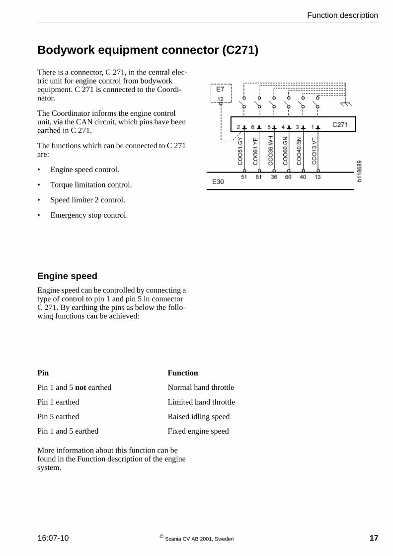
Bodywork equipment connector (C271)
There is a connector, C 271, in the central elec-tric unit for engine control from bodywork equipment. C 271 is connected to the Coordi-nator.
The Coordinator informs the engine control unit, via the CAN circuit, which pins have been earthed in C 271.
The functions which can be connected to C 271 are:
• Engine speed control.
• Torque limitation control.
• Speed limiter 2 control.
• Emergency stop control.
16:07-10 © Scania CV AB
n
h
h
g
Engine speedEngine speed can be controlled by connecting a type of control to pin 1 and pin 5 in connector C 271. By earthing the pins as below the follo-wing functions can be achieved:
a
a
li
i
More information about this function can be found in the Function description of the engine system.
Pin Functio
Pin 1 and 5 not earthed Normal
Pin 1 earthed Limited
Pin 5 earthed Raised id
Pin 1 and 5 earthed Fixed en
2
nd throttle
nd throttle
ng speed
ne speed
Function description
001, Sweden 17

18
e limitation
miter 1
miter 2
miter 3
Function description
Torque limitationEngine torque can be controlled by connecting a control to pin 3 and pin 4 in connector C 271. By earthing the pins as below the following functions can be achieved:
More information about this function can be found in the Function description of the engine system.
Speed limiter 2Speed limiter 2 can be activated by connecting a control to pin 6 in connector C 271. It is acti-vated when the pin is earthed.
More information about this function can be found in the Function description of the engine system.
Pin Function
Pin 3 and 4 not earthed No torqu
Pin 4 earthed Torque li
Pin 3 earthed Torque li
Pin 3 and 4 earthed Torque li
© Scania CV AB 2001, Swe
Emergency stopEmergency stop can be activated by connecting a control to pin 2 in connector C 271. It is acti-vated when the pin is earthed.
More information about this function can be found in the Function description of the Engine system.
den 16:07-10

Troubleshooting
Fault codes in the Coordi-natorReading of fault codes can be carried out by using Scania Diagnos or the diagnostic lamp in the instrument panel.
Reading fault codes
Switch on the ignition.
Depress the diagnostic switch and keep it depressed for 2 seconds.
When reading fault codes, a long flash indica-tes units of ten and a short flash indicates one unit. Example according to the illustration: Fault code 21 has the following flashes: Long - long - short. If there are no fault codes registe-red the lamp will be on for 4 seconds.
Depress the diagnostic switch once again to read the next fault code.
Clearing fault codes
Clear all fault codes as follows:
1 Begin by switching off the ignition (15 supply).
2 Press in the diagnostic switch and keep it depressed.
3 Switch on the ignition (15 supply) whilst still depressing the diagnostic switch.
Limitations
Despite the advanced software, a fault may arise which the control unit is unable to distin-guish from normal operation. If this is the case, no fault code is generated.
Fault codes may have been generated when a cable connection was disconnected whilst the ignition was on. This is quite a common occur-rence. The control unit will then interpret it as a
16:07-10 © Scania CV AB 2
fault.
In cases of loose connections the fault may no longer be present; but the fault code is stored in the control unit memory until it is cleared. It is then possible to see in which circuit the fault occurred and look for the cause there, even if there is currently no fault.
Faults that do not generate a fault codeIf there is no information from the engine con-trol unit about the coolant temperature, the gauge will show full heat, i.e. a maximum reading. No fault code is generated in the Coor-dinator.
If there is no information from the engine con-trol unit about the oil pressure, the gauge will show zero bars, i.e. no oil pressure. No fault code is generated in the Coordinator.
Troubleshooting
001, Sweden 19

20
List of fault codes
Fault code 11
Fault
Prohibited signal from the accelerator pedal sensor potentiometer.
Cause
Too low or too high input voltage to pin 54.
Remarks
The voltage from the potentiometer was below approximately 0.2 V or in excess of approx-imately 4.0 V.
The supply voltage and the resistance in the accelerator pedal potentiometer may however vary between vehicles, therefore the values are not exact, only reference values.
Action
Check the accelerator pedal potentiometer, the connectors and wiring.
© Scania CV AB 2001, Swe
Fault code 12
Fault
Prohibited deviation between the accelerator pedal sensor potentiometer and the throttle actuation switch.
Cause
Input voltage on pin 54 is too low at the same time as pin 30 is earthed. Alternatively, input voltage on pin 54 is too high at the same time as pin 30 is not earthed.
The voltage from the potentiometer was lower than 0.49 V while the throttle actuation switch was closed. Alternatively, the voltage was in excess of 0.90 V while the throttle actuation switch was open.
Remarks
The values of the throttle actuation switch and the potentiometer must correspond. The poten-tiometer may not indicate throttle actuation whilst the throttle actuation switch indicates idling speed.
Action
Check the potentiometer and the throttle actua-tion switch.
Check the connectors and wiring.
Troubleshooting
den 16:07-10

Fault code 13
Fault
Prohibited signal from the control for cruise control.
Cause
Voltage too low or too high between pins 29 and 48. The fault may also be a prohibited vol-tage level between the following functions: ACC, RES, RET, ON and OFF.
Remarks
Cruise control and engine idling speed adjust-ment will not function as long as the fault is present.
The control unit interprets the voltage level as follows:
0.7 - 0.9 V: ON+ACC, (14.4 - 18.3% of the supply)
1.6 - 1.7 V: ON+RES, (31.2 - 35.1% of the supply)
2.5 - 2.7 V: ON+RET, (49.6 - 53.5% of the supply)
3.3 - 3.5 V: ON, (66.4 - 70.3% of the supply)
3.7 - 4.3 V: OFF, (74.2 - 85.9% of the supply)
The voltage levels shown above apply to 5 V supply. The supply voltage may however vary between vehicles.
The fault code is generated in the event of vol-tage levels outside these ranges.
Action
Check the control, connectors and wiring.
16:07-10 © Scania CV AB 2
Fault code 14
Fault
No communication with the engine control unit.
Cause
Communication between the engine control unit and the coordinator control unit has been broken.
Remarks
The indicator lamp for engine control comes on. Fault codes from the engine cannot be read.
Action
Check the connectors and wiring.
Troubleshooting
001, Sweden 21

22
Fault code 17
Fault
The connection to the tachograph is broken or short circuited.
Cause
The input signal to pin 41 is missing or the vol-tage level is too low or too high. The fault code can only be generated when the road speed is 0 km/h.
Remarks
When the road speed is 0 km/h the control unit carries out a connection test with the tachog-raph. If the test shows prohibited measure-ments the fault code is generated.
Only the system that limits maximum road speed may be connected to tachograph output D3.
Action
Check the operation of the tachograph. If the tachograph is functioning correctly, check the wiring between the tachograph and the control unit.
© Scania CV AB 2001, Swe
Fault code 18
Fault
The brake pedal switches 1 and 2 have supplied conflicting signals on the position of the pedal. One switch has indicated that the pedal was released while the other switch has indicated that it was depressed.
Cause
Both pins 52 and 53 have been earthed at the same time or neither of them have been earthed at the same time.
Both brake pedal switches have been closed or been open at the same time for more than five minutes.
Remarks
The cruise control and engine idling speed adjustment will not function as long as the fault is present.
Action
Check the switches, the connectors and wiring.
Troubleshooting
den 16:07-10

Fault code 19
Fault
Short circuit of the PWM signal from the eng-ine concerning the amount of fuel supplied to the engine.
Cause
The signal from the output is short circuited to supply voltage.
The fault code is generated if the fault has been active for longer than 10 seconds.
Remarks
When this fault code is generated, fault codes may also be generated in other control units.
Action
Check the connectors and wiring.
16:07-10 © Scania CV AB 2
Fault code 21
Fault
Short circuit of the signal to the coolant tempe-rature gauge.
Cause
The signal from the output is short circuited to supply voltage.
The fault code is generated after the fault has been active for longer than 10 seconds.
Remarks
If this fault occurs the gauge will begin to indi-cate a lower temperature.
Action
Check the instrument cluster, the connectors and wiring.
Troubleshooting
001, Sweden 23
24
Fault code 22
Fault
Short circuit of the signal to the oil pressure gauge.
Cause
The signal from the output is short circuited to supply voltage.
The fault code is generated after the fault has been active for longer than 10 seconds.
Remarks
If this fault occurs the gauge will begin to indi-cate a higher pressure.
Action
Check the instrument cluster, the connectors and wiring.
© Scania CV AB 2001, Swe
Fault code 23
Fault
Short circuit of the signal to the oil pressure warning lamp.
Cause
The signal from the output is short circuited to supply voltage.
The fault code is generated after the fault has been active for longer than 10 seconds.
Remarks
If this fault occurs the warning lamp will not come on.
Action
Check the instrument cluster, the connectors and wiring.
Troubleshooting
den 16:07-10

Fault code 24
Fault
Short circuit of coordinator pin 2.
Cause
The signal from the output is short circuited to earth
The fault code is generated after the fault has been active for longer than 10 seconds.
Remarks
When the fault occurs the EDC warning lamp does not come on as this is connected to the output.
Action
Check the connectors and wiring.
16:07-10 © Scania CV AB 2
Fault code 25
Fault
The ways in which the coordinator and the eng-ine control unit communicate differ.
Cause
The coordinator does not have the support to give the engine control unit the information it requests.
Remarks
The fault code may be generated for example in connection with one of the control units being renewed with a spare part control unit.
A coordinator can adapt itself to older engine control units but not to newer ones. A newer engine control unit may for example request information that an older coordinator cannot supply.
Action
Ensure that the new control unit is of the same version as the old one.
Troubleshooting
001, Sweden 25

26
Electrical system
Connector
Connector
Removing tool 588 219, for smaller pins
116
966
Removing tool 588 192, for larger pins
118
437
Electrical system
© Scania CV AB 2001, Sweden 16:07-10

Input signalsThe table below shows which input signals the control unit receives.
Inpu
t sig
nals
*The
sig
nal v
arie
s, e
.g. d
epen
ding
on
how
muc
h th
e ac
cele
rato
r pe
dal i
s de
pres
sed.
Tas
kSo
urce
Sign
al t
ype
Pin
Igni
tion
(15
supp
ly)
Fuse
20
+24
V (
U+
)7
Dis
enga
gem
ent o
f cr
uise
con
trol
Dio
de u
nit
+24
V8
Dia
gnos
tic s
witc
hE
DC
indi
cato
r la
mp
Ear
thin
g (0
V)
9
Dia
gnos
tic s
witc
hD
iagn
ostic
pan
elE
arth
ing
(0 V
)12
Lim
ited
hand
thro
ttle
Bod
ywor
k eq
uipm
ent c
onne
ctor
Ear
thin
g (0
V)
13
Con
trol
of
crui
se c
ontr
ol a
nd h
and
thro
ttle
Con
trol
for
cru
ise
cont
rol
Ana
logu
e29
Dep
ress
ed a
ccel
erat
or p
edal
Thr
ottle
act
uatio
n sw
itch
Ear
thin
g (0
V)
30
Rai
sed
idlin
g sp
eed
Bod
ywor
k eq
uipm
ent c
onne
ctor
Ear
thin
g (0
V)
36
Inpu
t sig
nal f
or to
rque
lim
iter
2B
odyw
ork
equi
pmen
t con
nect
orE
arth
ing
(0 V
)40
Indi
cate
s th
e ro
ad s
peed
Tac
hogr
aph
Freq
uenc
y41
Initi
ated
ped
al m
ovem
ent
Clu
tch
peda
l sw
itch
Ear
thin
g (0
V)
50
Act
ivat
es e
mer
genc
y st
op f
unct
ion
Bod
ywor
k eq
uipm
ent c
onne
ctor
Ear
thin
g (0
V)
51
Dep
ress
ed b
rake
ped
alB
rake
ped
al s
witc
h 1
Ear
thin
g (0
V)
52
Dep
ress
ed b
rake
ped
alB
rake
ped
al s
witc
h 2
Ear
thin
g (0
V)
53
Dep
ress
ed a
ccel
erat
or p
edal
Pot
entio
met
erA
nalo
gue
54
Idlin
g sp
eed
requ
est
+24
V57
Inpu
t sig
nal f
or to
rque
lim
iter
1B
odyw
ork
equi
pmen
t con
nect
orE
arth
ing
(0 V
)60
Act
ivat
es s
peed
lim
iter
2B
odyw
ork
equi
pmen
t con
nect
orE
arth
ing
(0 V
)61
Electrical system
16:07-10 © Scania CV AB 2001, Sweden 27
28
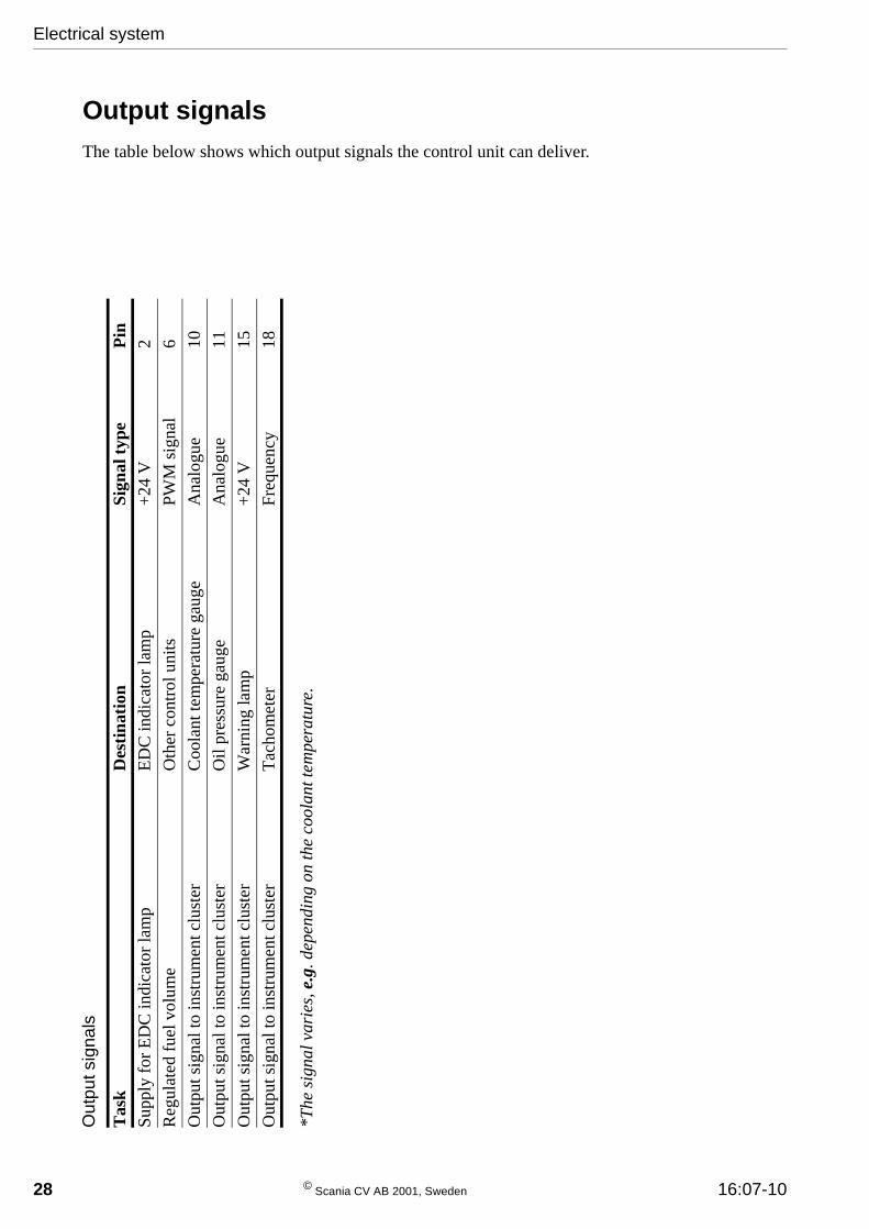
Output signalsThe table below shows which output signals the control unit can deliver.
Out
put s
igna
ls
*The
sig
nal v
arie
s, e
.g. d
epen
ding
on
the
cool
ant t
empe
ratu
re.
Tas
kD
esti
nati
onSi
gnal
typ
eP
inSu
pply
for
ED
C in
dica
tor
lam
pE
DC
indi
cato
r la
mp
+24
V2
Reg
ulat
ed f
uel v
olum
eO
ther
con
trol
uni
tsPW
M s
igna
l6
Out
put s
igna
l to
inst
rum
ent c
lust
erC
oola
nt te
mpe
ratu
re g
auge
Ana
logu
e10
Out
put s
igna
l to
inst
rum
ent c
lust
erO
il pr
essu
re g
auge
Ana
logu
e11
Out
put s
igna
l to
inst
rum
ent c
lust
erW
arni
ng la
mp
+24
V15
Out
put s
igna
l to
inst
rum
ent c
lust
erT
acho
met
erFr
eque
ncy
18
Electrical system
© Scania CV AB 2001, Sweden 16:07-10

Other signalsThe table below shows the control unit connections for voltage supply, system earth, communication cables etc.
Oth
er s
igna
ls
Tas
kSo
urce
/Des
tina
tion
Sign
al t
ype
Pin
Ear
thin
g of
the
cont
rol u
nit
G13
Ear
thin
g (0
V)
1
Com
mun
icat
ion
CA
N c
ircu
itD
ata/
Mes
sage
s21
Ear
thin
g of
the
cont
rol u
nit
G13
Ear
thin
g (0
V)
23
Ear
thin
g of
acc
eler
ator
ped
al s
uppl
y0
V24
Vol
tage
sup
ply
for
the
cont
rol u
nit (
30 s
uppl
y).
Fuse
19
+24
V26
Vol
tage
sup
ply
to th
e po
tent
iom
eter
in th
e th
rottl
e pe
dal s
enso
rPo
tent
iom
eter
+5
V28
Com
mun
icat
ion
CA
N c
ircu
itD
ata/
Mes
sage
s45
Ear
thin
g of
the
cont
rol f
or th
e cr
uise
con
trol
Con
trol
for
cru
ise
cont
rol
0 V
48
Vol
tage
sup
ply
to th
e co
ntro
l uni
tFu
se 1
9+
24 V
49
Com
mun
icat
ion
K c
able
Dat
a65
Electrical system
16:07-10 © Scania CV AB 2001, Sweden 29

30
Wiring DiagramsCurrent path 1 - 25
Current path 26 - 50
Electrical system
© Scania CV AB 2001, Sweden 16:07-10

Current path 51 - 75
Current path 76 - 100
Electrical system
16:07-10 © Scania CV AB 2001, Sweden 31