knife gate valve mv - ebro armaturenru.ebro-armaturen.com/fileadmin/downloads/knife gate... · ·...
TRANSCRIPT
1 2013-01-14 issue 19Data is only for informational purpose. All specifications are subject to change without notice.
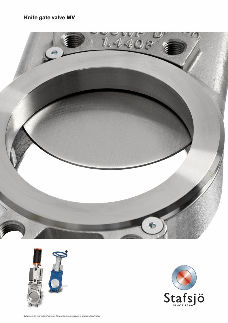
Knife gate valve MV
2 2013-01-14 issue 19
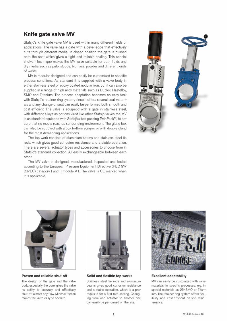
Knife gate valve MVStafsjö’s knife gate valve MV is used within many different fields of applications. The valve has a gate with a bevel edge that effectively cuts through different media. In closed position the gate is pushed onto the seat which gives a tight and reliable sealing. This special shut-off technique makes the MV valve suitable for both fluids and dry media such as pulp, sludge, biomass, powder and different kinds of waste.
MV is modular designed and can easily be customized to specific process conditions. As standard it is supplied with a valve body in either stainless steel or epoxy coated nodular iron, but it can also be supplied in a range of high alloy materials such as Duplex, Hastelloy, SMO and Titanium. The process adaptation becomes an easy task with Stafsjö’s retainer ring system, since it offers several seat materi-als and any change of seat can easily be performed both smooth and cost-efficient. The valve is equipepd with a gate in stainless steel, with different alloys as options. Just like other Stafsjö valves the MV is as standard equipped with Stafsjö’s box packing TwinPack™, to se-cure that no media reaches surrounding environment. The gland box can also be supplied with a box bottom scraper or with double gland for the most demanding applications.
The top work consists of aluminium beams and stainless steel tie rods, which gives good corrosion resistance and a stable operation. There are several actuator types and accessories to choose from in Stafsjö’s standard collection. All easily exchangeable between each other.
The MV valve is designed, manufactured, inspected and tested according to the European Pressure Equipment Directive (PED 97/ 23/EC) category I and II module A1. The valve is CE marked when it is applicable.
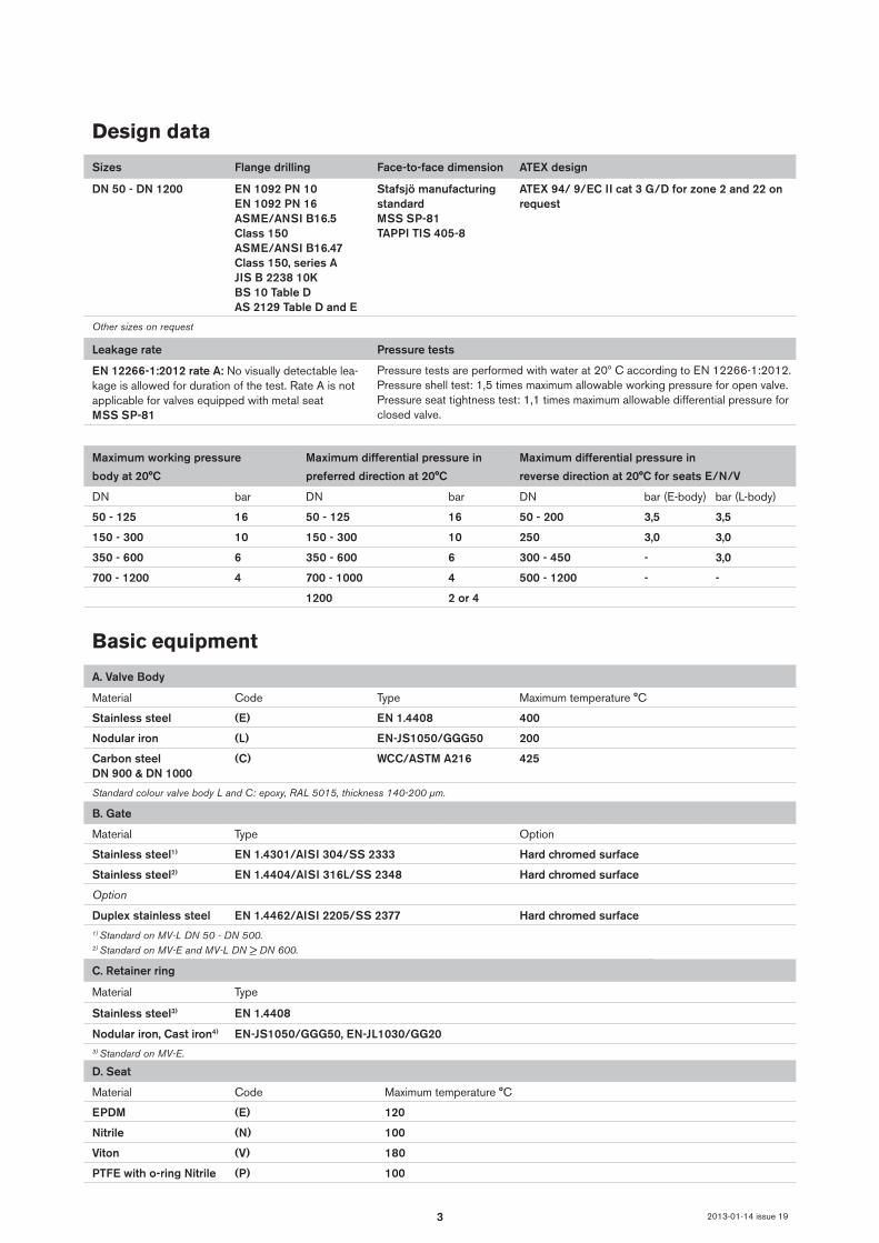
Excellent adaptabilityMV can easily be customized with valve materials to specific processes, e.g. in special materials as 254SMO or Titan-ium. The retainer ring system offers flex-ibility and cost-efficient on-site main-tenance.
Proven and reliable shut-offThe design of the gate and the valve body, especially the bore, gives the valve its ability to securely and effectively shut-off almost any flow. Minimal friction makes the valve easy to operate.
Solid and flexible top worksStainless steel tie rods and aluminium beams gives good corrosion resistance and a stable operation, which is a pre- requisite for a first-rate sealing. Chang-ing from one actuator to another one can easily be performed on the site.
3 2013-01-14 issue 19
Design data
Sizes Flange drilling Face-to-face dimension ATEX design
DN 50 - DN 1200 EN 1092 PN 10EN 1092 PN 16ASME/ANSI B16.5 Class 150ASME/ANSI B16.47 Class 150, series AJIS B 2238 10KBS 10 Table DAS 2129 Table D and E
Stafsjö manufacturing standardMSS SP-81TAPPI TIS 405-8
ATEX 94/ 9/EC II cat 3 G/D for zone 2 and 22 on request
Other sizes on request
Leakage rate Pressure tests
EN 12266-1:2012 rate A: No visually detectable lea-kage is allowed for duration of the test. Rate A is not applicable for valves equipped with metal seatMSS SP-81
Pressure tests are performed with water at 20º C according to EN 12266-1:2012.Pressure shell test: 1,5 times maximum allowable working pressure for open valve.Pressure seat tightness test: 1,1 times maximum allowable differential pressure for closed valve.
Maximum working pressure
body at 20°C
Maximum differential pressure in
preferred direction at 20°C
Maximum differential pressure in
reverse direction at 20°C for seats E/N/V
DN bar DN bar DN bar (E-body) bar (L-body)
50 - 125 16 50 - 125 16 50 - 200 3,5 3,5
150 - 300 10 150 - 300 10 250 3,0 3,0
350 - 600 6 350 - 600 6 300 - 450 - 3,0
700 - 1200 4 700 - 1000 4 500 - 1200 - -
1200 2 or 4
Basic equipment
A. Valve Body
Material Code Type Maximum temperature °C
Stainless steel (E) EN 1.4408 400
Nodular iron (L) EN-JS1050/GGG50 200
Carbon steelDN 900 & DN 1000
(C) WCC/ASTM A216 425
Standard colour valve body L and C: epoxy, RAL 5015, thickness 140-200 µm.
B. Gate
Material Type Option
Stainless steel1) EN 1.4301/AISI 304/SS 2333 Hard chromed surface
Stainless steel2) EN 1.4404/AISI 316L/SS 2348 Hard chromed surface
Option
Duplex stainless steel EN 1.4462/AISI 2205/SS 2377 Hard chromed surface1) Standard on MV-L DN 50 - DN 500.2) Standard on MV-E and MV-L DN > DN 600.
C. Retainer ring
Material Type
Stainless steel3) EN 1.4408
Nodular iron, Cast iron4) EN-JS1050/GGG50, EN-JL1030/GG203) Standard on MV-E.4) Nodular iron on MV-L DN < DN 300 and cast iron on MV-L > DN 350. Standard colour on retainer ring: epoxy, RAL 5015, thickness 140-200 µm.D. Seat
Material Code Maximum temperature °C
EPDM (E) 120
Nitrile (N) 100
Viton (V) 180
PTFE with o-ring Nitrile (P) 100
4 2013-01-14 issue 19
Actuators
Manual Code Automatic Code
Hand wheel5) (HW) Pneumatic cylinder (AC)
Chain wheel6) (CW) Electrical motor (EM)
Hand lever6)7) (HL) Hydraulic cylinder6) (MH)
Ratchet wrench6) (RW)
Bevel gear6) (BG)5) For recommended size, see page 5 column E6) For recommended size, see separate data sheet7) Pressures according to design data are not valid for valve equipped with hand lever (HL). Maximum working and differential pressure in preferred direction at 20°C for DN 50 - DN 200: 4 bar.
Double-acting pneumatic cylinder Electric motor (AUMA multi-turn)
DN valve EC type Maximum force (kN) DN valve AUMA type Attachment
50 - 150 EC 100 3,5 50 - 150 SA 07.2 F10/A
200 - 300 EC 160 9,0 200 - 250 SA 07.6 F10/A
350 - 500 EC 200 14,1 300 - 600 SA 10.2 F10/A
600 - 700 EC 250 22,1 700 - 800 SA 14.2 F14/A
750 - 1000 EC 320 36,2 900 - 1000 SA 14.6 F14/A
1200 - - 1200 SA 16.2 F16/A
The table above gives recommended cylinder sizes at normal operation with 5 bar air pressure. For other operating conditions, please contact Stafsjö or your local representative for advice.
Electric motors are mounted according to standard ISO 5210. The table above gives recommended motor sizes at normal operation. For other operating conditions, please contact Stafsjö or your local representative for advice.
The actuators are described in separate data sheets. For advice and information on other actuators or on ATEX-classified ones, please contact Stafsjö or your local representative.
PTFE with o-ring Viton (PV) 180
Polyurethane (U) 90
Metal with o-ring Nitrile (M) 100
Metal with o-ring Viton (MV) 180
Metal with Grafoil (MHT) 400 (E)/200 (L)/425 (C)
E. Box Packing
Material Code Maximum temperature °C
TwinPackTM (TY) 260
PTFE (TF) 280
Garlock 127 (TG) 650
Options and accessories
Knife gate valve
Accessories Code Model Design
Mechanical limit switch (MLS) Omron D4V 12-250 V AC/12-125 V DC, IP 65
Inductive limit switch (ILS) ifm electronic IG0006 2-wire, 20-250 V AC/DC, IP 67
ifm electronic IG5401 3-wire, 10-36 V DC PNP, IP 67
Stem extension (SES) Short Pipe Length < 1,5 m
(SEL) Long Pipe Length > 1,5 m
Positioner for control (POS) PMV Palmstierna/Metso/ABB
Purge ports (PP) MV DN 50 - DN 450 on order
MV DN 500 - DN 1200 are equipped with purge ports.
Pipe thread G1/2” acc. to ISO 228/1
Double gland (DG) For MV DN 80 - DN 400 Stainless steel (EN 1.4408)
Box bottom scraper (BBS) Available on order Available in Nonfric, UHMWPE, PTFE or Brass
5 2013-01-14 issue 19
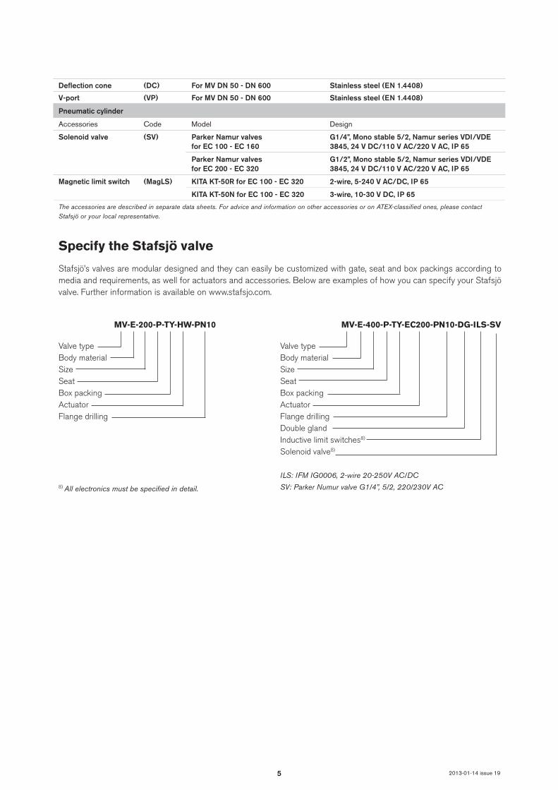
Deflection cone (DC) For MV DN 50 - DN 600 Stainless steel (EN 1.4408)
V-port (VP) For MV DN 50 - DN 600 Stainless steel (EN 1.4408)
Pneumatic cylinder
Accessories Code Model Design
Solenoid valve (SV) Parker Namur valves for EC 100 - EC 160
G1/4”, Mono stable 5/2, Namur series VDI/VDE 3845, 24 V DC/110 V AC/220 V AC, IP 65
Parker Namur valves for EC 200 - EC 320
G1/2”, Mono stable 5/2, Namur series VDI/VDE 3845, 24 V DC/110 V AC/220 V AC, IP 65
Magnetic limit switch (MagLS) KITA KT-50R for EC 100 - EC 320 2-wire, 5-240 V AC/DC, IP 65
KITA KT-50N for EC 100 - EC 320 3-wire, 10-30 V DC, IP 65
The accessories are described in separate data sheets. For advice and information on other accessories or on ATEX-classified ones, please contact Stafsjö or your local representative.
Specify the Stafsjö valve
Stafsjö’s valves are modular designed and they can easily be customized with gate, seat and box packings according to media and requirements, as well for actuators and accessories. Below are examples of how you can specify your Stafsjö valve. Further information is available on www.stafsjo.com.
Valve typeBody materialSizeSeatBox packingActuatorFlange drillingDouble glandInductive limit switches8)
Solenoid valve8)
ILS: IFM IG0006, 2-wire 20-250V AC/DC
SV: Parker Numur valve G1/4”, 5/2, 220/230V AC
MV-E-400-P-TY-EC200-PN10-DG-ILS-SV
Valve typeBody materialSizeSeatBox packingActuatorFlange drilling
MV-E-200-P-TY-HW-PN10
8) All electronics must be specified in detail.
6
1
2
3
4
21
8c
8b
8a
8 9
12a
12
10
13
10a11
10b
14
2a2b
9a
5b
5a
5
204a
4b
25
28
6
7
17
16
18
15
2013-01-14 issue 19
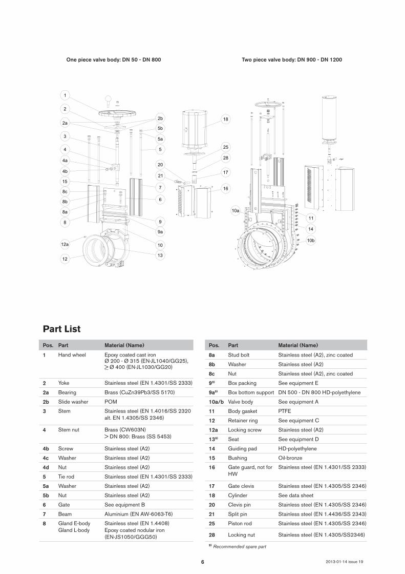
One piece valve body: DN 50 - DN 800 Two piece valve body: DN 900 - DN 1200
Part List
Pos. Part Material (Name) Pos. Part Material (Name)
1 Hand wheel Epoxy coated cast ironØ 200 - Ø 315 (EN-JL1040/GG25), > Ø 400 (EN-JL1030/GG20)
8a Stud bolt Stainless steel (A2), zinc coated
8b Washer Stainless steel (A2)
8c Nut Stainless steel (A2), zinc coated
2 Yoke Stainless steel (EN 1.4301/SS 2333) 99) Box packing See equipment E
2a Bearing Brass (CuZn39Pb3/SS 5170) 9a9) Box bottom support DN 500 - DN 800 HD-polyethylene
2b Slide washer POM 10a/b Valve body See equipment A
3 Stem Stainless steel (EN 1.4016/SS 2320 alt. EN 1.4305/SS 2346)
11 Body gasket PTFE
12 Retainer ring See equipment C
4 Stem nut Brass (CW603N)> DN 800: Brass (SS 5453)
12a Locking screw Stainless steel (A2)
139) Seat See equipment D
4b Screw Stainless steel (A2) 14 Guiding pad HD-polyethylene
4c Washer Stainless steel (A2) 15 Bushing Oil-bronze
4d Nut Stainless steel (A2) 16 Gate guard, not for HW
Stainless steel (EN 1.4301/SS 2333)
5 Tie rod Stainless steel (EN 1.4301/SS 2333)
5a Washer Stainless steel (A2) 17 Gate clevis Stainless steel (EN 1.4305/SS 2346)
5b Nut Stainless steel (A2) 18 Cylinder See data sheet
6 Gate See equipment B 20 Clevis pin Stainless steel (EN 1.4305/SS 2346)
7 Beam Aluminium (EN AW-6063-T6) 21 Split pin Stainless steel (EN 1.4436/SS 2343)
8 Gland E-bodyGland L-body
Stainless steel (EN 1.4408)Epoxy coated nodular iron (EN-JS1050/GGG50)
25 Piston rod Stainless steel (EN 1.4305/SS 2346)
28 Locking nut Stainless steel (EN 1.4305/SS2346)
9) Recommended spare part
7
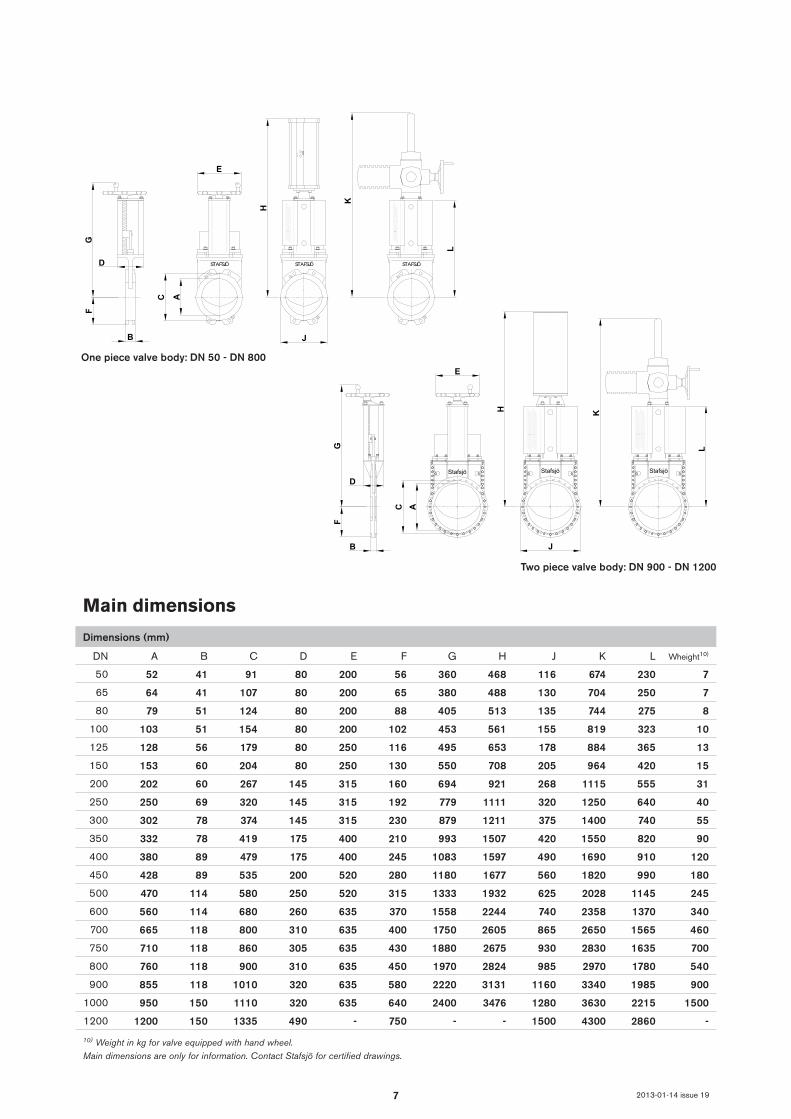
DN A B C D E F G H J K L
50 52 41 91 80 200 56 360 468 116 674 230 7
65 64 41 107 80 200 65 380 488 130 704 250 7
80 79 51 124 80 200 88 405 513 135 744 275 8
100 103 51 154 80 200 102 453 561 155 819 323 10
125 128 56 179 80 250 116 495 653 178 884 365 13
150 153 60 204 80 250 130 550 708 205 964 420 15
200 202 60 267 145 315 160 694 921 268 1115 555 31
250 250 69 320 145 315 192 779 1111 320 1250 640 40
300 302 78 374 145 315 230 879 1211 375 1400 740 55
350 332 78 419 175 400 210 993 1507 420 1550 820 90
400 380 89 479 175 400 245 1083 1597 490 1690 910 120
450 428 89 535 200 520 280 1180 1677 560 1820 990 180
500 470 114 580 250 520 315 1333 1932 625 2028 1145 245
600 560 114 680 260 635 370 1558 2244 740 2358 1370 340
700 665 118 800 310 635 400 1750 2605 865 2650 1565 460
750 710 118 860 305 635 430 1880 2675 930 2830 1635 700
800 760 118 900 310 635 450 1970 2824 985 2970 1780 540
900 855 118 1010 320 635 580 2220 3131 1160 3340 1985 900
1000 950 150 1110 320 635 640 2400 3476 1280 3630 2215 1500
1200 1200 150 1335 490 - 750 - - 1500 4300 2860 -
E
KH
C A
B
FG
D
J
Stafsjö Stafsjö Stafsjö
L
STAFSJÖ STAFSJÖ STAFSJÖ
GF
E
AC
H
D
B J
L
KE
KH
C A
B
FG
D
J
Stafsjö Stafsjö Stafsjö
L
STAFSJÖ STAFSJÖ STAFSJÖ
GF
EAC
HD
B J
L
K
2013-01-14 issue 19
Main dimensions
Dimensions (mm)
Wheight10)
One piece valve body: DN 50 - DN 800
Two piece valve body: DN 900 - DN 1200
10) Weight in kg for valve equipped with hand wheel.Main dimensions are only for information. Contact Stafsjö for certified drawings.
8
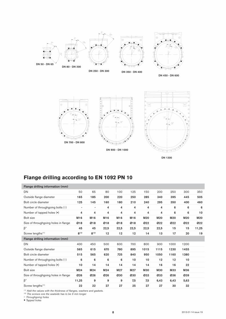
DN 700 - DN 800
DN 900 - DN 1000
DN 1200
DN 50 - DN 65DN 80 - DN 200
DN 250 - DN 300 DN 350 - DN 400DN 450 - DN 600
2013-01-14 issue 19
Flange drilling according to EN 1092 PN 10
Flange drilling information (mm)
DN 50 65 80 100 125 150 200 250 300 350
Outside flange diameter 165 185 200 220 250 285 340 395 445 505
Bolt circle diameter 125 145 160 180 210 240 295 350 400 460
Number of throughgoing bolts (○) - - 4 4 4 4 4 6 6 6
Number of tapped holes (●) 4 4 4 4 4 4 4 6 6 10
Bolt size M16 M16 M16 M16 M16 M20 M20 M20 M20 M20
Size of throughgoing holes in flange Ø18 Ø18 Ø18 Ø18 Ø18 Ø22 Ø22 Ø22 Ø22 Ø22
β° 45 45 22,5 22,5 22,5 22,5 22,5 15 15 11,25
Screw lengths11) 812) 812) 12 12 12 14 13 17 20 19
Flange drilling information (mm)
DN 400 450 500 600 700 800 900 1000 1200
Outside flange diameter 565 615 670 780 895 1015 1115 1230 1455
Bolt circle diameter 515 565 620 725 840 950 1050 1160 1380
Number of throughgoing bolts (○) 6 6 6 6 10 10 12 12 10
Number of tapped holes (●) 10 14 14 14 14 14 16 16 22
Bolt size M24 M24 M24 M27 M27 M30 M30 M33 M36
Size of throughgoing holes in flange Ø26 Ø26 Ø26 Ø30 Ø30 Ø33 Ø33 Ø36 Ø39
β° 11,25 9 9 9 7,5 7,5 6,43 6,43 5,63
Screw lengths11) 22 22 27 27 25 27 27 30 3211) Add the values with the thickness of flanges, washers and gaskets.12) The screws one the seatside has to be 3 mm longer○ Throughgoing holes● Tapped holes

9
DN 50 - DN 65DN 80 - DN 150
DN 200 - DN 300 DN 350 - DN 400DN 450 - DN 600
DN 700 - DN 800
DN 900 - DN 1000
DN 1200
2013-01-14 issue 19
Flange drilling according to EN 1092 PN 16
Flange drilling information (mm)
DN 50 65 80 100 125 150 200 250 300 350
Outside flange diameter (mm) 165 185 200 220 250 285 340 405 460 520
Bolt circle diameter (mm) 125 145 160 180 210 240 295 355 410 470
Number of throughgoing bolts (○) - - 4 4 4 4 6 6 6 6
Number of tapped holes (●) 4 4 4 4 4 4 6 6 6 10
Bolt size M16 M16 M16 M16 M16 M20 M20 M24 M24 M24
Size of throughgoing holes in flange Ø18 Ø18 Ø18 Ø18 Ø18 Ø22 Ø22 Ø26 Ø26 Ø26
β° 45 45 22,5 22,5 22,5 22,5 15 15 15 11,25
Screw lengths11) 812) 812) 12 12 12 14 13 17 20 19
Flange drilling information (mm)
DN 400 450 500 600 700 800 900 1000 1200
Outside flange diameter 580 640 715 840 910 1025 1125 1255 1485
Bolt circle diameter 525 585 650 770 840 950 1050 1170 1390
Number of throughgoing bolts (○) 6 6 6 6 10 10 12 12 10
Number of tapped holes (●) 10 14 14 14 14 14 16 16 22
Bolt size M27 M27 M30 M33 M33 M36 M36 M39 M45
Size of throughgoing holes in flange Ø30 Ø30 Ø33 Ø36 Ø36 Ø39 Ø39 Ø42 Ø48
β° 11,25 9 9 9 7,5 7,5 6,43 6,43 5,63
Screw lengths11) 22 22 27 27 25 27 27 30 3211) Add the values with the thickness of flanges, washers and gaskets.12) The screws one the seatside has to be 3 mm longer○ Throughgoing holes● Tapped holes
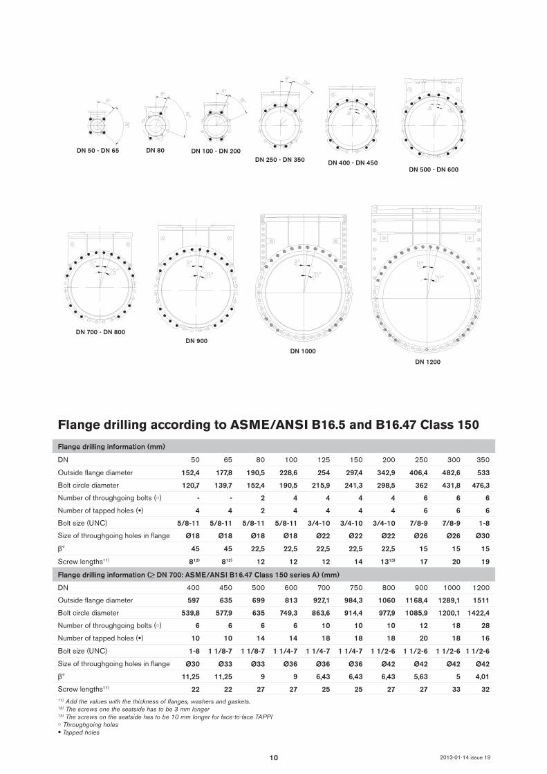
10
DN 80DN 50 - DN 65 DN 100 - DN 200DN 250 - DN 350 DN 400 - DN 450
DN 500 - DN 600
DN 700 - DN 800DN 900
DN 1000
DN 1200
2013-01-14 issue 19
Flange drilling information (> DN 700: ASME/ANSI B16.47 Class 150 series A) (mm)
DN 400 450 500 600 700 750 800 900 1000 1200
Outside flange diameter 597 635 699 813 927,1 984,3 1060 1168,4 1289,1 1511
Bolt circle diameter 539,8 577,9 635 749,3 863,6 914,4 977,9 1085,9 1200,1 1422,4
Number of throughgoing bolts (○) 6 6 6 6 10 10 10 12 18 28
Number of tapped holes (●) 10 10 14 14 18 18 18 20 18 16
Bolt size (UNC) 1-8 1 1/8-7 1 1/8-7 1 1/4-7 1 1/4-7 1 1/4-7 1 1/2-6 1 1/2-6 1 1/2-6 1 1/2-6
Size of throughgoing holes in flange Ø30 Ø33 Ø33 Ø36 Ø36 Ø36 Ø42 Ø42 Ø42 Ø42
β° 11,25 11,25 9 9 6,43 6,43 6,43 5,63 5 4,01
Screw lengths11) 22 22 27 27 25 25 27 27 33 3211) Add the values with the thickness of flanges, washers and gaskets.12) The screws one the seatside has to be 3 mm longer13) The screws on the seatside has to be 10 mm longer for face-to-face TAPPI○ Throughgoing holes● Tapped holes
Flange drilling according to ASME/ANSI B16.5 and B16.47 Class 150
Flange drilling information (mm)
DN 50 65 80 100 125 150 200 250 300 350
Outside flange diameter 152,4 177,8 190,5 228,6 254 297,4 342,9 406,4 482,6 533
Bolt circle diameter 120,7 139,7 152,4 190,5 215,9 241,3 298,5 362 431,8 476,3
Number of throughgoing bolts (○) - - 2 4 4 4 4 6 6 6
Number of tapped holes (●) 4 4 2 4 4 4 4 6 6 6
Bolt size (UNC) 5/8-11 5/8-11 5/8-11 5/8-11 3/4-10 3/4-10 3/4-10 7/8-9 7/8-9 1-8
Size of throughgoing holes in flange Ø18 Ø18 Ø18 Ø18 Ø22 Ø22 Ø22 Ø26 Ø26 Ø30
β° 45 45 22,5 22,5 22,5 22,5 22,5 15 15 15
Screw lengths11) 812) 812) 12 12 12 14 1313) 17 20 19

11
DN 700 - DN 750 DN 800
DN 80 - DN 150DN 50 - DN 65DN 200 - DN 250 DN 300 DN 350 - DN 400 DN 450 - DN 500 DN 600
DN 900 - DN 1000
2013-01-14 issue 19
Flange drilling according to JIS B 2238 10K
Flange drilling information (mm)
DN 50 65 80 100 125 150 200 250 300 350
Outside flange diameter 155 175 185 210 250 280 330 400 445 490
Bolt circle diameter 120 140 150 175 210 240 290 355 400 445
Number of throughgoing bolts (○) - - 4 4 4 4 6 6 8 6
Number of tapped holes (●) 4 4 4 4 4 4 6 6 8 10
Bolt size M16 M16 M16 M16 M20 M20 M20 M22 M22 M22
Size of throughgoing holes in flange Ø19 Ø19 Ø19 Ø19 Ø23 Ø23 Ø23 Ø25 Ø25 Ø25
β° 45 45 22,5 22,5 22,5 22,5 15 15 15 11,25
Screw lengths11) 812) 812) 12 12 12 14 13 17 20 19
Flange drilling information (mm)
DN 400 450 500 600 700 750 800 900 1000
Outside flange diameter 550 620 675 795 905 970 1020 1120 1235
Bolt circle diameter 510 565 620 730 840 900 950 1050 1160
Number of throughgoing bolts (○) 6 6 6 6 10 10 10 12 12
Number of tapped holes (●) 10 14 14 18 14 14 18 16 16
Bolt size M24 M24 M24 M30 M30 M30 M30 M30 M36
Size of throughgoing holes in flange Ø27 Ø27 Ø27 Ø33 Ø33 Ø33 Ø33 Ø33 Ø39
β° 11,25 9 9 7,5 7,5 7,5 6,43 6,43 6,43
Screw lengths11) 22 22 27 27 25 25 27 27 3011) Add the values with the thickness of flanges, washers and gaskets.12) The screws one the seatside has to be 3 mm longer○ Throughgoing holes● Tapped holes
12
Stafsjö Valves AB. SE-618 95 Stavsjö, Sweden. Tel: +46 (0)11-39 31 00. Fax: +46 (0)11-39 30 67. [email protected] www.stafsjo.comA Bröer Group company 2013-01-14 issue 19
Globally active. Locally represented.AFRICA South Africa: Valve & Automation (Pty) Ltd, ASIA China: EBRO ARMATUREN (BEIJING) CO., LTD, India: Ebro Armaturen India Pvt. Ltd, Indonesia: Contromatic Prima Mandiri PT, Japan: SKC Co. Ltd, Malaysia: Precision Control SdnBnd, Philippines: EBRO ARMATUREN (PHILIPPINES) INC., Thailand: EBRO VALVES (Trading) Co. Ltd., Vietnam: EBRO VALVES (Thailand) Co., Ltd, AUSTRALIA WITH OCEANIA Australia: EBRO ARMATUREN Pacific PTY. LTD, New Zeeland: H.J.Asmuss&Co.Ltd, EUROPE Austria: EBRO ARMATUREN GmbH, Belgium: V.C.T. - Valve & Connector Technology n.v., Denmark: Valtor Industri A/S, Finland: Tecalemit Flow Oy, France: EBRO ARMATUREN and GL&V, Germany: EBRO ARMATUREN Gebr. Bröer GmbH, Great Britain: EBRO Valves Ltd, Hungary: EBRO ARMATUREN Kft, Ireland: Induchem Components Ltd, Iceland: Hédinn HF, Italy: EBRO VALVOLE SRL, The Netherlands: EBRO VALVES B.V., Norway: BAGGES AS, Poland: EBRO ARMATUREN GmbH, Portugal: AxFlow Comércio de Aquipamentos LDA, RUSSIA/BELARUS/UKRAINE: EBRO ARMATUREN and LesBumMash Ltd, Spain: EBRO ARMATUREN ESPAÑA, S.L., Switzerland: EBRO Armaturen Est. & Co. KG, Sweden: Stafsjö Valves AB and Ahlsell, Turkey: EBRO ARMATUREN Otomasyon Sistemleri San ve Tic Ltd. Sti NORTH & SOUTH AMERICA Argentina: ESCO ARGENTINA S.A, Brazil: Ebro Stafsjö Valves do Brasil LTD, Canada: Armour Valve Ltd, Chile: Ebro Stafsjö Valves Chile Ltd, USA: EBRO ARMATUREN USA Inc., For other countries, please contact us directly.
Further information is available on www.stafsjo.com