km-1300sah-e service manual - hoshizaki · service manual stackable crescent cuber for qualified...
TRANSCRIPT

SERVICE MANUAL
STACKABLE CRESCENT CUBER
FOR QUALIFIED SERVICE PERSON
89/33673/23
HOSHIZAKI
NUMBER: 73124ISSUED: December 17, 2004
KM-1300SAH-E
2
IMPORTANTOnly qualified service technicians should attempt to service or maintain thisicemaker. No service or maintenance should be undertaken until the technicianhas thoroughly read this Service Manual.
TEL: +44 (0) 1707322493FAX: +44 (0) 1707322315
Hoshizaki Care Branch Offices:
BeneluxTEL: +31 (0) 206918499FAX: +31 (0) 206918768
GermanyTEL: +49 (0) 215492810FAX: +49 (0) 2154928128
FranceTEL: +33 (0) 148137130FAX: +33 (0) 148130992
Note:To expedite assistance, all correspondence/communication MUST include thefollowing information:
• Model Number
• Serial Number
• Complete and detailed explanation of the problem
HOSHIZAKI provides this manual primarily to assist qualified service technicians in theservice and maintenance of the icemaker.
Should the reader have any questions or concerns which have not been satisfactorilyaddressed, please call HOSHIZAKI CARE for assistance.

3
CONTENTSI. Specifications .................................................................................................................... 5
KM-1300SAH-E (air-cooled) ............................................................................................ 5II. General Information .......................................................................................................... 6
A. Construction ................................................................................................................. 6KM-1300SAH-E ......................................................................................................... 6
B. Controller Board ........................................................................................................... 71. Solid-State Control ................................................................................................. 72. Controller Board ..................................................................................................... 73. Sequence ............................................................................................................. 114. Controls and Adjustments .................................................................................... 145. Checking the Controller Board ............................................................................. 17
III. Technical Information ..................................................................................................... 19A. Water Circuit and Refrigerant Circuit .......................................................................... 19
KM-1300SAH-E ....................................................................................................... 19B. Wiring Diagram .......................................................................................................... 20
KM-1300SAH-E ....................................................................................................... 20C. Timing Chart .............................................................................................................. 21D. Performance Data ...................................................................................................... 23
KM-1300SAH-E ....................................................................................................... 23IV. Service Diagnosis .......................................................................................................... 24
A. No Ice Production ...................................................................................................... 24B. Evaporator is Frozen Up ............................................................................................ 28C. Low Ice Production .................................................................................................... 29D. Abnormal Ice .............................................................................................................. 29E. Other .......................................................................................................................... 29
V. Removal and Replacement of Components ................................................................... 30A. Service for Refrigerant Lines ...................................................................................... 30
1. Refrigerant Recovery ............................................................................................ 302. Evacuation and Recharge [R-404A] ..................................................................... 30
B. Brazing ....................................................................................................................... 30C. Removal and Replacement of Compressor ............................................................... 32D. Removal and Replacement of Drier ........................................................................... 33E. Removal and Replacement of Expansion Valve ........................................................ 34F. Removal and Replacement of Hot Gas Valve ............................................................. 35G. Removal and Replacement of Evaporator ................................................................. 36H. Removal and Replacement of Thermistor .................................................................. 37I. Removal and Replacement of Fan Motor .................................................................... 38J. Removal and Replacement of Water Valve ................................................................. 39K. Removal and Replacement of Pump Motor................................................................ 39L. Removal and Replacement of Float Switch................................................................ 40M. Removal and Replacement of Spray Tubes............................................................... 41
Please review this manual. It should be read carefully before the icemaker is serviced ormaintenance operations performed. Only qualified service technicians should service andmaintain the icemaker. This manual should be made available to the technician prior toservice or maintenance.

4
VI. Cleaning and Maintenance Instructions ........................................................................ 42A. Preparing the Icemaker for Long Storage ................................................................... 42B. Cleaning and Sanitizing Procedures ......................................................................... 44
1. Cleaning Procedure ............................................................................................. 442. Sanitizing Procedure - Following Cleaning Procedure ......................................... 46
C. Maintenance .............................................................................................................. 47

5
Note: We reserve the right to make changes in specifications and design without prior notice.
I. SpecificationsKM-1300SAH-E (air-cooled)
AC SUPPLY VOLTAGE 220-240/50/1AMPERAGE 11.5 A ( 5 Min. Freeze AT 104°F / WT 80°F)MINIMUM CIRCUIT AMPACITY 20 AMAXIMUM FUSE SIZE 20 AAPPROXIMATE ICE PRODUCTION Ambient WATER TEMP. (°F)PER 24 HR. Temp.(°F) 50 70 90 lbs./day ( kg/day ) 70 *1200 (544) 1106 (502) 988 (448) Reference without *marks 80 1129 (512) 983 (446) 871 (395)
90 1106 (502) 880 (400) 763 (346)100 1086 (493) 853 (387) 655 (297)
FOR THE EUROPEAN MARKET 10/10 °C 20/15 °C 30/25 °CICE CAPACITY lbs./day ( kg/day ) 1321 (600) 1183 (538) 877 (399)SHAPE OF ICE Crescent CubeICE PRODUCTION PER CYCLE 30.1 lbs. ( 13.7 kg ) 1440 pcs.APPROXIMATE STORAGE CAPACITY N/AELECTRIC & WATER CONSUMPTION 90/70°F 70/50°F ELECTRIC W (kWH/100 lbs.) 2050 (5.5) 1870 (3.7) WATER gal./24HR (gal./100 lbs.) 295 (33.4) 512 (42.7)EXTERIOR DIMENSIONS (WxDxH) 48" x 27-3/8" x 27-3/8" (1219 x 695 x 695 mm)EXTERIOR FINISH Stainless Steel, Galvanized Steel (Rear) WEIGHT Net 275 lbs. ( 125 kg ), Shipping 315 lbs. ( 143 kg )CONNECTIONS - ELECTRIC Permanent - Connection - WATER SUPPLY Inlet 1/2" FPT - DRAIN Outlet 3/4" FPT - CONDENSATE DRAIN 3/8" OD PipeCUBE CONTROL SYSTEM Float SwitchHARVESTING CONTROL SYSTEM Hot Gas and Water, Thermistor and TimerICE MAKING WATER CONTROL Timer Controlled. Overflow PipeCOOLING WATER CONTROL N/ABIN CONTROL SYSTEM ThermostatCOMPRESSOR Hermetic, Model CS14K6E-PFJCONDENSER Air-cooled, Fin and Tube typeEVAPORATOR Vertical type, Stainless Steel and CopperREFRIGERANT CONTROL Thermostatic Expansion ValveREFRIGERANT CHARGE R-404A, 3 lbs. 14 oz. ( 1750 g )DESIGN PRESSURE High 467 PSIG, Low 230 PSIGP.C. BOARD CIRCUIT PROTECTION High Voltage Cut-out ( Internal )COMPRESSOR PROTECTION Auto-reset Overload Protector ( Internal )REFRIGERANT CIRCUIT PROTECTION Auto-reset High Pressure Control SwitchLOW WATER PROTECTION Float SwitchACCESSORIES -SUPPLIED N/A -REQUIRED Ice Storage BinOPERATING CONDITIONS VOLTAGE RANGE 198 - 254 V
AMBIENT TEMP. 45 -100° FWATER SUPPLY TEMP. 45 - 90° FWATER SUPPLY PRESSURE 10 - 113 PSIG
6
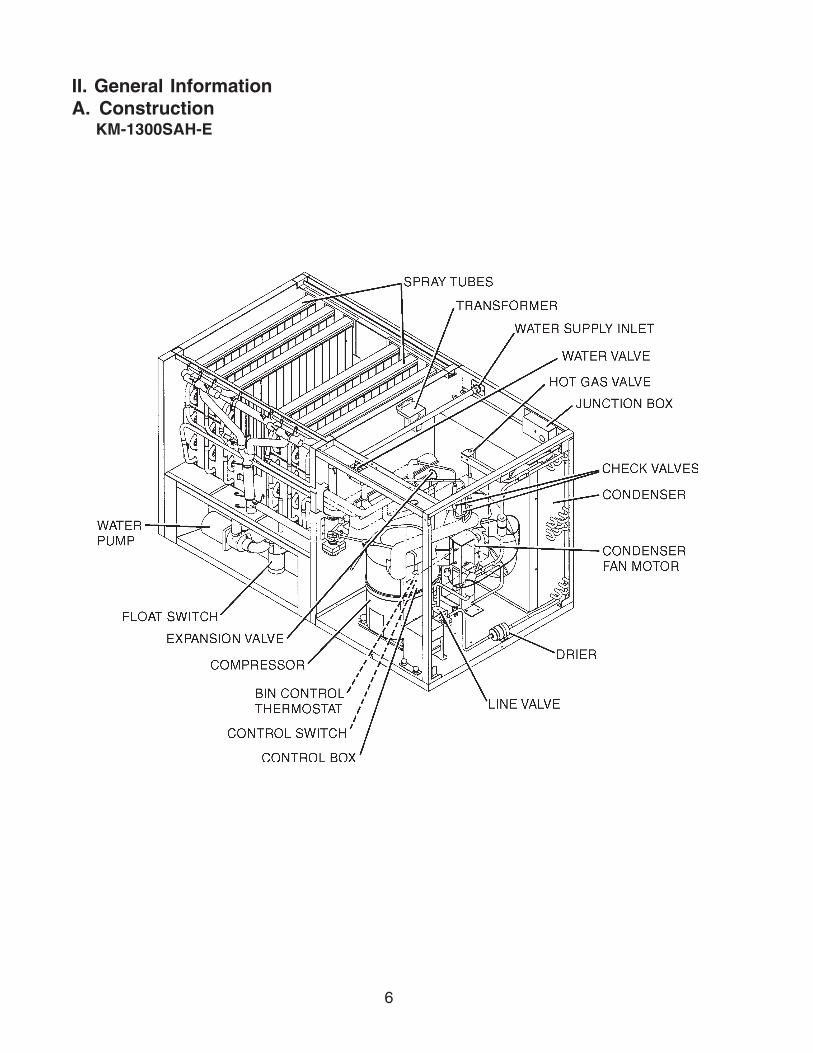
II. General InformationA. Construction
KM-1300SAH-E

7
B. Controller Board1. Solid-State Control
a) A HOSHIZAKI exclusive solid-state control is employed in KM-1300S_H-E SeriesStackable Crescent Cubers.
b) A printed circuit board (hereafter called “controller board”) includes a stable and highquality control system.
c) All models are pretested and factory-adjusted.
2. Controller Board
CAUTION1. Fragile, handle very carefully.2. A controller board contains integrated circuits, which are susceptible to
failure due to static discharge. It is especially important to touch the metalpart of the unit when handling or replacing the board.
3. Do not touch the electronic devices on the board or the back of the board toprevent damage to the board.
4. Do not change wiring and connections. Do not misconnect K3, K4 and K5,because the same connector is used for the thermistor and float switch. K4 isnot connected.
5. Always replace the whole board assembly when it goes bad.6. Do not short out power supply to test for voltage.
Features of Control Products “E” Controller Board
a) Maximum Water Supply Period - 6 minutes
Water solenoid valve opening in the defrost (harvest) cycle is limited by the defrost timer.The water valve cannot remain open longer than the maximum period. The water valvecan close in less than six minutes if the defrost cycle is completed.
b) Defrost Timer
The defrost cycle starts when the float switch opens and completes the freeze cycle. Butthe defrost timer does not start counting until the thermistor senses 9°C at the evaporatoroutlet. The period from the end of the freeze cycle up to the point of the thermistor'ssensing varies depending on the ambient and water temperatures.
Part Number Type2A1410-01 HOS-001A (Control Products - 10 Pin)
Controller Board

8
c) High Temperature Safety — 53 ± 4°C
The temperature of the suction line in the refrigerant circuit is limited by the hightemperature safety. During the defrost cycle the evaporator temperature rises. Thethermistor senses 9°C and starts the defrost timer. After the defrost timer counts down tozero, the normal freeze cycle begins. If the evaporator temperature continues to rise, thethermistor will sense the rise in temperature and at 53 ±4°C the thermistor operates thehigh temperature safety. This high temperature safety shuts down the circuit and theicemaker automatically stops. To reset the safety, turn the power off and back on again.This high temperature safety protects the unit from excessive temperature. The controlboard will beep every 3 seconds. The white reset button on the control board must bepressed with power on to reset the safety.
d) Low Water Safety
If the pump motor is operated without water, the mechanical seal can fail. To prevent thistype of failure, the controller board checks the position of the float switch at the end of theinitial one minute water fill cycle and at the end of each defrost cycle.If the float switch is in the up position (electrical circuit closed), the controller boardchanges to the ice making cycle. If the float switch is in the down position (electricalcircuit open), the controller board changes to a one minute water fill cycle before startingthe ice making cycle. This method allows for a low water safety shut down to protect thewater pump from mechanical seal failure.
e) High Voltage Cut-out — control voltage > 147Vac ±5%
The maximum allowable supply voltage of this icemaker is limited by the high voltagecut-out. If miswiring causes excessive voltage on the controller board, the high voltagecut-out shuts down the circuit in 3 seconds and the icemaker automatically stops. Whenthe proper supply voltage is resumed, the icemaker automatically starts running again.The control board will signal this problem using 7 beeps every 3 seconds.
f) LED Lights and Audible Alarm Safeties
The red LED indicates proper control voltage and will remain on unless a control voltageproblem occurs. At startup a 5 second delay occurs while the board conducts an internaltimer check. A short beep occurs when the power switch is turned ON or OFF.
9
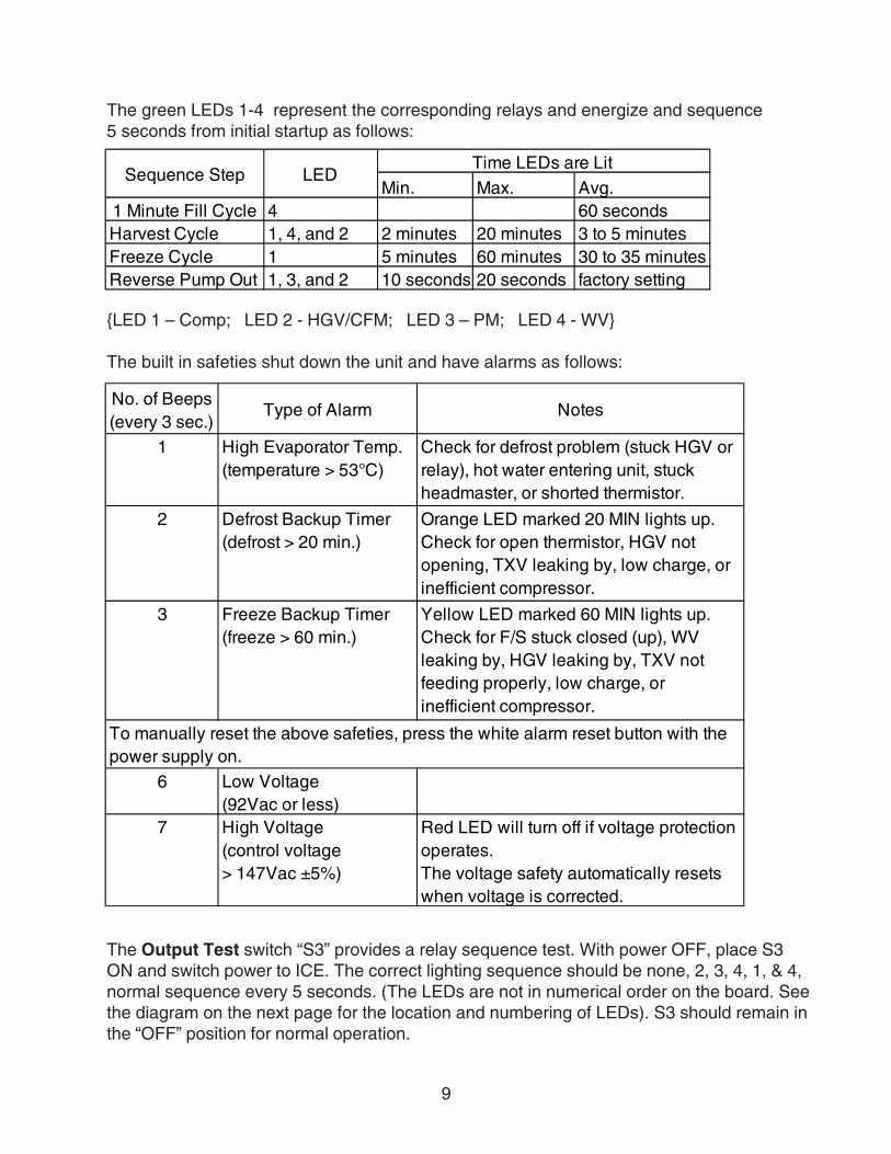
The green LEDs 1-4 represent the corresponding relays and energize and sequence5 seconds from initial startup as follows:
LED 1 – Comp; LED 2 - HGV/CFM; LED 3 – PM; LED 4 - WV
The built in safeties shut down the unit and have alarms as follows:
The Output Test switch “S3” provides a relay sequence test. With power OFF, place S3ON and switch power to ICE. The correct lighting sequence should be none, 2, 3, 4, 1, & 4,normal sequence every 5 seconds. (The LEDs are not in numerical order on the board. Seethe diagram on the next page for the location and numbering of LEDs). S3 should remain inthe “OFF” position for normal operation.
Min. Max. Avg.1 Minute Fill Cycle 4 60 secondsHarvest Cycle 1, 4, and 2 2 minutes 20 minutes 3 to 5 minutesFreeze Cycle 1 5 minutes 60 minutes 30 to 35 minutesReverse Pump Out 1, 3, and 2 10 seconds 20 seconds factory setting
Time LEDs are Lit LEDSequence Step
No. of Beeps(every 3 sec.)
Type of Alarm Notes
1 High Evaporator Temp. (temperature > 53°C)
Check for defrost problem (stuck HGV or relay), hot water entering unit, stuck headmaster, or shorted thermistor.
2 Defrost Backup Timer(defrost > 20 min.)
Orange LED marked 20 MIN lights up.Check for open thermistor, HGV not opening, TXV leaking by, low charge, or inefficient compressor.
3 Freeze Backup Timer(freeze > 60 min.)
Yellow LED marked 60 MIN lights up.Check for F/S stuck closed (up), WV leaking by, HGV leaking by, TXV not feeding properly, low charge, or inefficient compressor.
6 Low Voltage(92Vac or less)
7 High Voltage(control voltage > 147Vac ±5%)
Red LED will turn off if voltage protection operates. The voltage safety automatically resets when voltage is corrected.
To manually reset the above safeties, press the white alarm reset button with the power supply on.

10
The application switch located between relay X3 & X4 must be set to match the originalboard application. Place this switch in the ALP position if there is no white wire supplied tothe K1 connector. If there is a white wire, place the switch in the C position. If this switch isplaced in the wrong position either the compressor contactor will remain energized with thecontrol switch OFF or the unit will not start.
The dip switches should be adjusted per the adjustment chart published in the Tech Specsbook. 7 & 8 must remain in the OFF position.
(Control Products HOS-001A Board)
11
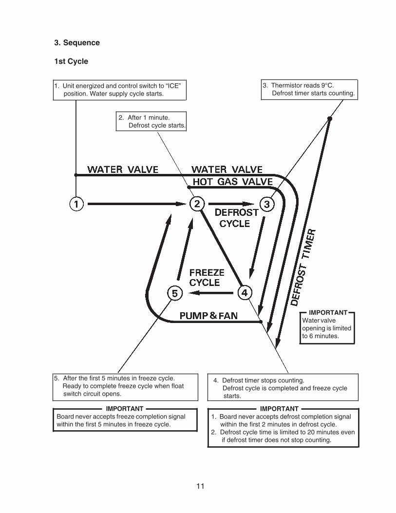
4. Defrost timer stops counting. Defrost cycle is completed and freeze cycle starts.
3. Sequence
1st Cycle
1. Unit energized and control switch to “ICE” position. Water supply cycle starts.
2. After 1 minute. Defrost cycle starts.
5. After the first 5 minutes in freeze cycle. Ready to complete freeze cycle when float switch circuit opens.
IMPORTANT1. Board never accepts defrost completion signal within the first 2 minutes in defrost cycle.2. Defrost cycle time is limited to 20 minutes even if defrost timer does not stop counting.
3. Thermistor reads 9°C. Defrost timer starts counting.
IMPORTANTBoard never accepts freeze completion signalwithin the first 5 minutes in freeze cycle.
IMPORTANTWater valveopening is limitedto 6 minutes.

12
2nd Cycle and after with pump drain
IMPORTANTFreeze cycle time is limited by the freeze timerfactory setting even if the float switch does notopen.
1. Float switch opens and signals to complete freeze cycle. Drain timer starts counting.
2. Drain timer stops counting. Pump drain is completed.
3. Thermistor reads 9°C. Defrost timer starts counting.
IMPORTANTWater valveopening is limited to 6minutes.
5. After the first 5 minutes in freeze cycle. Ready to complete freeze cycle whenfloat switch circuit opens.
4. Defrost timer stops counting. Defrost cycle is completed and freeze cycle starts.
IMPORTANTBoard never accepts freeze completion signalwithin the first 5 minutes in freeze cycle.
IMPORTANT1. Board never accepts defrost completion signal within the first 2 minutes in defrost cycle.2. Defrost cycle time is limited to 20 minutes even if defrost timer does not stop counting.
&
13
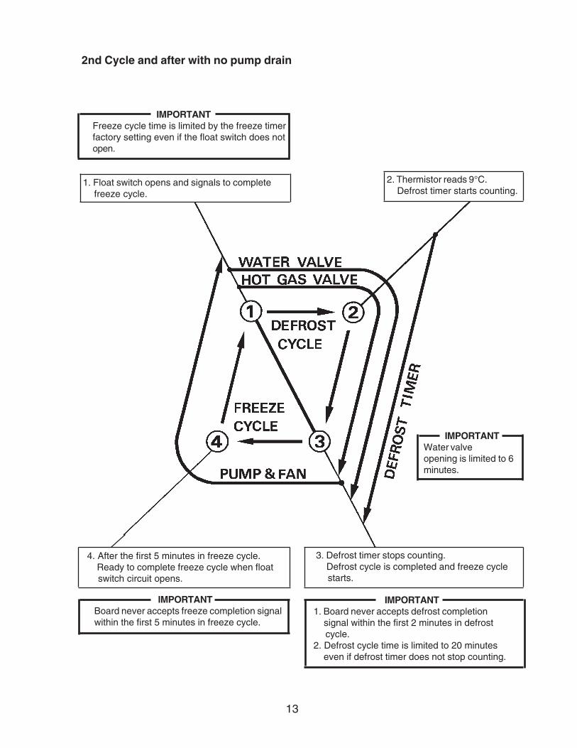
2nd Cycle and after with no pump drain
IMPORTANTFreeze cycle time is limited by the freeze timerfactory setting even if the float switch does notopen.
1. Float switch opens and signals to complete freeze cycle.
2. Thermistor reads 9°C. Defrost timer starts counting.
IMPORTANTWater valveopening is limited to 6minutes.
4. After the first 5 minutes in freeze cycle. Ready to complete freeze cycle when float switch circuit opens.
3. Defrost timer stops counting. Defrost cycle is completed and freeze cycle starts.
IMPORTANTBoard never accepts freeze completion signalwithin the first 5 minutes in freeze cycle.
IMPORTANT1. Board never accepts defrost completion signal within the first 2 minutes in defrost cycle.2. Defrost cycle time is limited to 20 minutes even if defrost timer does not stop counting.

14
4. Controls and Adjustments
The dip switch is factory-adjusted to the following positions:
Dip Switch No. 1 2 3 4 5 6 7 8 9 10KM-1300SAH-E OFF OFF ON ON OFF OFF OFF OFF ON OFF
Switch Nos. 1 and 2:Used for adjustment of the defrost timer. The defrost timer starts counting when thethermistor reads a certain temperature at the evaporator outlet.
Switch Nos. 3 and 4:Used for adjustment of the drain timer. When a freeze cycle is completed, the pumpmotor stops, and the icemaker resumes operation in 2 seconds. Then the pump motordrains the water tank for the time determined by the drain timer. The drain timer alsodetermines the time to restrain completion of a defrost cycle, i.e. the minimum defrosttime.
Switch Nos. 5 and 6:Used for adjustment of the drain counter. The pump motor drains the water tank at thefrequency determined by the drain counter.
Switch Nos. 7 and 8:Used only for checking the controller board. Usually set in OFF position.
Switch Nos. 9 and 10:
Used for adjustment of freeze timer.The freeze timer determines maximumfreeze cycle time. Upon termination offreeze timer, machine initiates theharvest cycle. After 2 consecutive timerterminations, machine will shut down,possibly indicating a problem.

15
a) Defrost Control
A thermistor (semiconductor) is used for a defrost control sensor. The resistance variesdepending on the suction line temperatures. The thermistor detects the temperature ofthe evaporator outlet to start the defrost timer. No adjustment is required. If necessary,check for resistance between thermistor leads, and visually check the thermistormounting, located on the suction line next to the evaporator outlet.
Check a thermistor for resistance by using the following procedures.
(1) Disconnect the connector K3 on the board.
(2) Remove the thermistor. See “V. H. Removal and Replacement of Thermistor.”
(3) Immerse the thermistor sensor portion in a glass containing ice and water for 2 or 3 minutes.
(4) Check for a resistance between thermistor leads. Normal reading is within 3.5 to 7 kΩ. Replace the thermistor if it exceeds the normal reading.
b) Defrost Timer
No adjustment is required under normal use, as the defrost timer is adjusted to thesuitable position. However, if necessary because all the ice formed on the evaporatordoes not fall into the bin in the harvest cycle, adjust the defrost timer to a longer settingby adjusting the dip switch (No. 1 & 2) on the controller board.
-18 14.401-12 10.6130 6.000
10 3.87121 2.47432 1.633
Temperature (°C) Resistance (kΩ)
No. 1 No. 2OFF OFF 60ON OFF 90OFF ON 120ON ON 180
Dip Switch Setting Time(seconds)

16
c) Drain Timer
The drain timer is factory-adjusted and no adjustment is required.
T1: Time to drain the water tankT2: Time to restrain defrost completion
d) Drain Counter
CAUTIONDo not adjust the drain counter, or the evaporator may freeze up.
The drain counter is factory-adjusted to drain the water tank every 10 cycles, and noadjustment is required. However, where water quality is bad and the icemaker needs apump drain more often, the drain counter can be adjusted as shown in the table below.
No. 3 No. 4 T1 T2OFF OFF 10 150ON OFF 10 180OFF ON 10 120ON ON 20 180
Dip Switch Setting Time (seconds)
No. 5 No. 6OFF OFF every cycleON OFF every 2 cyclesOFF ON every 5 cyclesON ON every 10 cycles
Dip Switch Setting Frequency

17
e) Freeze TimerCAUTION
Adjust to proper specification, or the unit may not operate correctly.
The freeze timer is factory adjusted and no adjustment is required. This settingdetermines the maximum allowed freeze time to prevent possible freeze-up issues.
f) Bin ControlCAUTION
When the ambient temperature is below 7°C, the bin control thermostatoperates to stop the icemaker even if the ice storage bin is empty. When thethermostat is set in the prohibited range, the icemaker operates continuouslyeven if the ice storage bin is filled with ice. Setting in the prohibited range mightcause severe damage to the icemaker resulting in failure.
No adjustment is required under normal use, as the bin control is factory-adjusted. Adjust it,if necessary, so that the icemaker stops automatically within 10 seconds after ice contactsthe bin control thermostat bulb.
5. Checking the Controller Board
1) Visually check the sequence with the icemaker operating.
2) Visually check the controller board by using the following procedures:
(i) Adjust the defrost timer to minimum position.Disconnect the thermistor from the controller board.Connect a 1.5 kΩ - 3.5 kΩ resistor to the connector K3 (pins #1 and #2), and energize theunit.
After the 1 minute ± 5 second water supply cycle and the 2 minute ± 10 second defrostcycle, the unit should start the freeze cycle.
No. 9 No. 10OFF OFF 60OFF ON 50ON OFF 70ON ON 75
Dip Switch Setting Time(minutes)

18
(ii) After the above step (i), disconnect the float switch leads from the controller board withinthe first 5 minutes of the freeze cycle.
The unit should go into the defrost cycle after the first 5 minutes ± 20 seconds of thefreeze cycle.
(iii) Reconnect the float switch connector to the controller board. After the first 5 minutes ofthe freeze cycle, disconnect the float switch leads from the controller board.
At this point, the unit should start the defrost cycle.
(iv) After step (iii), de-energize the unit and confirm that the defrost timer is in the minimumposition. Disconnect the resistor from the controller board, and energize the unit.After the 1 minute water supply cycle, the defrost cycle starts.Re-connect a 1.5 kΩ - 3.5 kΩ resistor to the connector K3 (pins #1 and #2) after the first2 minutes of the defrost cycle. The unit should start the freeze cycle after 1 minute ± 5seconds from the resistor connection.
3) Check the controller board using the controller board’s test program.
The output test switch “S3” provides a relay sequence test. With power OFF, place S3 onand switch power to ICE. The correct lighting sequence should be none, 2, 3, 4, 1, and 4,normal sequence every 5 seconds. S3 should remain in the “OFF” position for normaloperation.

19
III. Technical InformationA. Water Circuit and Refrigerant Circuit
KM-1300SAH-E

20
B. Wiring DiagramKM-1300SAH-E
Pressure Switch
Cut-out 412 psig28.4 bar
Cut-in 327 ± 21 psig22.5 ± 1.5 bar
+21- 0+1.5- 0

21
C. Timing Chart
*1 The icemaker does not complete a defrost cycle in the first 2 or 3 minutes. See “II.B.4. Controls andAdjustments.”

22
*1 The pump motor waits for 2 seconds before starting a drain cycle. See “II.B.4. Controls and Adjustments.”
*2 The icemaker does not complete a defrost cycle in the first 2 or 3 minutes. See “II.B.4. Controls andAdjustments.”

23
D. Performance DataKM-1300SAH-E
Note: Pressure data is recorded at 5 minutes into freeze cycle. The data not in bold should be used for reference only.
We reserve the right to make changes in specifications and design without prior notice.
70/21 1200 544 1106 502 988 44880/27 1129 512 983 446 871 39590/32 1106 502 880 400 763 346
lbs./day kg./day 100/38 1086 493 853 387 655 29770/2180/2790/32
watts 100/3870/21 512 1.94 448 1.70 401 1.5280/27 464 1.75 365 1.38 339 1.2890/32 448 1.70 295 1.12 259 0.98
gal./day m3/day 100/38 452 1.71 287 1.08 226 0.8670/2180/2790/32
min. 100/38
70/2180/2790/32
min. 100/3870/21 240 16.9 268 18.8 287 20.280/27 261 18.4 304 21.4 313 22.090/32 268 18.8 335 23.6 348 24.5
PSIG kg/cm2G 100/38 265 18.6 338 23.8 360 25.370/21 50 3.5 51 3.6 54 3.880/27 51 3.6 53 3.8 56 3.990/32 51 3.6 55 3.9 58 4.1
PSIG kg/cm2G 100/38 52 3.7 56 3.9 60 4.2
443.5
2628
2933
3540
WATER TEMP. (°F/°C)AMBIENT TEMP. (°F/°C) 50/10 70/21 90/32
187019101923
APPROXIMATE ICE PRODUCTION PER 24 HR.
APPROXIMATE ELECTRIC CONSUMPTION
APPROXIMATE WATER CONSUMPTION PER 24 HR.
FREEZING CYCLE TIME
1927
1923199220502062
1977203621002145
SUCTION PRESSURE
TOTAL HEAT OF REJECTION
382931
37
HARVEST CYCLE TIME
HEAD PRESSURE4
5
20,400 BTU/h [AT 90°F (32°C) / WT 70°F (21°C)]
4349
444
444
3.5

24
IV. Service DiagnosisA. No Ice Production
Problem Possible Cause Remedy
[1] a) Power Supply 1. OFF position. 1. Move to ON position.
2. Loose connection. 2. Tighten.
3. Bad contacts. 3. Check for continuity and replace.
4. Voltage too high. 4. Check and get recommended voltage.
b) Fuse (Inside fused disconnect, if any)
1. Blown. 1. Check for short circuit and replace.
c) Control Switch 1. OFF position. 1. Move to ICE position.
2. Bad contacts. 2. Check for continuity and replace.
d) Bin Control Thermostat 1. Tripped with bin filled with ice.
1. Remove ice.
2. Ambient temperature too cool.
2. Increase ambient temperature.
3. Set too warm. 3. See "II.B.4. Controls and Adjustments, f) Bin Control."
4. Bulb out of position. 4. Place in position.
5. Bad contacts or leaks in bulb.
5. Check for continuity and replace.
e) High Pressure Control 1. Bad contacts. 1. Check for continuity and replace.
f) Transformer 1. Thermal fuse blown or coil winding opened.
1. Replace.
g) Wiring to Controller Board
1. Loose connections or open.
1. Check for continuity and replace.
h) Thermistor 1. Leads short-circuit or open and high temperature safety operates.
1. See "II.B.4. Controls and Adjustments, a) Defrost Control."
i) Hot Gas Solenoid Valve
1. Continues to open in freeze cycle and high temperature safety operates.
1. Check for power off in freeze cycle and replace.
The icemaker will not start.

25
Problem Possible Cause Remedy
[1] Continued from previous page.
j) Water Supply Line 1. Water supply off and water supply cycle does not finish.
1. Check and get recommended pressure.
2. Condenser water pressure too low or off and pressure control opens and closes frequently to finally operate high temperature safety.
2. Check and get recommended pressure.
k) Water Solenoid 1. Mesh filter or orifice gets clogged and water supply cycle does not finish.
1. Clean.
2. Coil winding opened. 2. Replace.
3. Wiring to water valve. 3. Check for loose connection or open, and replace.
l) Controller Board 1. Defective. 1. See "II.B.5. Checking the Controller Board."
[2] a) Float Switch 1. Connector disconnected.
1. Place in position.
2. Leads opened or defective switch.
2. Check and replace.
3. Float does not move freely.
3. Clean or replace.
b) Controller Board 1. Defective. 1. Replace.
c) Contactor 1. Open coil or contacts worn.
1. Replace.
[3] a) Wash Switch 1. WASH position. 1. Move to ICE position.
2. Bad contacts. 2. Check and replace.
b) High Pressure Control 1. Dirty air filter or condenser.
1. Clean.
2. Ambient or condenser water temperature too warm.
2. Reduce temperature.
3. Refrigerant overcharged.
3. Recharge.
4. Refrigerant line or components plugged.
4. Clean and replace drier.
5. Fan not operating. 5. See chart A.[6]
Compressor will not start or stops operating.
Water continues to be supplied, and the icemaker will not start.

26
Problem Possible Cause Remedy
[3] c) Overload Protector 1. Bad contacts. 1. Check for continuity and replace.
2. Voltage too low. 2. Increase voltage.
3. Refrigerant overcharged or undercharged.
3. Recharge.
4. Line valve continues to close in freeze cycle and overload protector operates.
4. Check line valve's operation in freeze cycle and replace.
d) Starter 1. Bad contacts. 1. Check and replace.
2. Coil winding opened. 2. Replace.
e) Start Capacitor or Run Capacitor
1. Defective. 1. Replace.
f) Magnetic Contactor 1. Bad contacts. 1. Check for continuity and replace.
2. Coil winding opened. 2. Replace.
g) Compressor 1. Wiring to compressor. 1. Check for loose connection or open, and replace.
2. Defective. 2. Replace.
3. Protector tripped. 3. Reduce temperature.
h) Controller Board 1. Defective. 1. See "II.B.5. Checking the Controller Board."
[4] a) Water Solenoid Valve 1. Diaphragm does not close.
1. Check for water leaks with icemaker off.
b) Controller Board 1. Defective. 1. See "II.B.5. Checking the Controller Board."
[5] a) Water Supply Line 1. Water pressure too low and water level in water tank too low.
1. Check and get recommended pressure.
b) Water Solenoid Valve 1. Dirty mesh filter or orifice and water level in water tank too low.
1. Clean.
c) Water System 1. Water leaks. 1. Check connections for water leaks, and replace.
2. Clogged. 2. Clean.
3. Pump out check valve leaking by.
3. Check assembly and clean.
Water continues to be supplied in freeze cycle.
No water comes from spray tubes. Water pump will not start, or freeze cycle time is too short.
Continued from previous page.

27
Problem Possible Cause Remedy
[5] d) Pump Motor 1. Motor winding opened. 1. Replace.
2. Bearing worn out. 2. Replace.
3. Wiring to pump motor. 3. Check for loose connection or open, and replace.
4. Defective capacitor. 4. Replace.
5. Defective or bound impeller.
5. Replace and clean.
6. Mechanical seal worn out.
6. Check and replace.
e) Controller Board 1. Defective. 1. See "II.B.5. Checking the Controller Board."
[6] a) Fan Motor 1. Motor winding opened. 1. Replace.
2. Bearing worn out. 2. Replace.
3. Wiring to fan motor. 3. Check for loose connection or open, and replace.
4. Defective capacitor. 4. Replace.
5. Fan blade bound. 5. Check and replace.
b) Controller Board 1. Defective. 1. See "II.B.5. Checking the Controller Board."
[7] a) Refrigerant 1. Undercharged. 1. Check for leaks and recharge.
2. Air or moisture trapped. 2. Replace drier and recharge.
b) Compressor 1. Defective valve. 1. Replace.
c) Hot Gas Solenoid Valve
1. Continues to open in freeze cycle.
1. Check and replace.
d) Line Valve 1. Continues to close in freeze cycle.
1. Check and replace.
e) Water Solenoid Valve 1. Water solenoid valve is wide open during freeze.
1. Check for water leaks with icemaker off.
Fan motor will not start, or is not operating.
All components run, but no ice is produced.
Continued from previous page.

28
B. Evaporator is Frozen UpProblem Possible Cause Remedy
[1] a) Float Switch 1. Leads short-circuit or defective switch.
1. Check and replace.
2. Float does not move freely.
2. Clean or replace.
b) Water Solenoid Valve 1. Diaphragm does not close.
1. Check for water leaks with icemaker off.
c) Controller Board 1. Defective. 1. See "II.B.5. Checking the Controller Board."
[2] a) Evaporator 1. Scaled up. 1. Clean.
b) Water Supply Line 1. Water pressure too low. 1. Check and get recommended pressure.
c) Water Filter System (if installed)
1. Dirty/Restricted 1. Replace filter.
d) Water Solenoid Valve 1. Dirty mesh filter or orifice.
1. Clean.
2. Diaphragm does not close.
2. Check for water leaks with icemaker off.
e) Ambient and/or water temperature.
1. Too cool. 1. Increase temperature.
f) Line Valve 1. Continues to open in harvest cycle.
1. Check operation in harvest cycle and replace.
g) Thermistor 1. Out of position or loose attachment.
1. See "V.H. Removal and Replacement of Thermistor."
h) Controller Board 1. Defrost timer is set too short.
1. Adjust longer, referring to "II.B.4. Controls and Adjustments, b) Defrost Timer."
2. Defective. 2. See "II.B.5. Checking the Controller Board."
[3] Other a) Spray Tubes 1. Clogged. 1. Clean.
2. Out of position. 2. Place in position.
b) Water System 1. Dirty. 1. Clean.
c) Refrigerant 1. Undercharged. 1. Check for leaks and recharge.
d) Expansion Valve 1. Bulb out of position or loose attachment.
1. Place in position.
2. Defective. 2. Replace.
e) 1. Coil winding opened. 1. Replace.
2. Plunger does not move. 2. Replace.
3. Wiring to hot gas valve. 3. Check for loose connection or open, and replace.
f) Water Supply Line 1. Too small; requires 1/2" OD line dedicated per machine.
1. Increase water line size.
Freeze cycle time is too long.
All ice formed on evaporator does not fall into bin in harvest cycle.
Hot Gas Solenoid Valve

29
C. Low Ice Production
D. Abnormal Ice
E. Other
Problem Possible Cause Rem edy
[1] a)
b)
[2] Harvest cyc le time is long.
a)
See chart A .[3] and check high pressure controller.
See chart B .[1] and check float switch, water solenoid valve and controller board.
See chart B .[2] and check evaporator, water supply line, water filter sys tem, water solenoid valve, ambient and/or water temperature, line valve, therm istor, and controller board.
Freeze cycle time is long.
Problem Possible Cause Remedy
[1] Small cubes. a) Ice Cube Guide 1. Out of position. Circulated water falls into bin.
1. Place in position.
b)
c) Pump Out Check Valve
1. Dirty. 1. Clean.
[2] Cloudy or irregular cubes.
a)
b) Spray Guide 1. Dirty. 1. Clean.
c) Water Quality 1. High hardness or contains impurities.
1. Install a water softener or filter.
See chart A.[5] and check water supply line, water solenoid valve, water system, pump motor, and controller board.
See chart B.[1] and B.[3], and check float switch, water solenoid valve, controller board, spray tubes, water system, refrigerant charge, and expansion valve.
Problem Possible Cause Remedy
[1] a) Bin Control Thermostat 1. Set too cold. 1. Adjust warmer.
2. Defective. 2. Replace.
[2] Abnormal noise. a) Pump Motor 1. Bearings worn out. 1. Replace.
b) Fan Motor 1. Bearings worn out. 1. Replace.
2. Fan blade deformed. 2. Replace fan blade.
3. Fan blade does not move freely.
3. Replace.
c) Compressor 1. Bearings worn out or cylinder valve broken.
1. Replace.
2. Mounting pad out of position.
2. Reinstall.
d) Refrigerant Lines 1. Rub or touch other lines or surfaces.
1. Replace.
[3] a) Bin Drain 1. Plugged. 1. Clean.
b) Icemaker and Bin 1. Drains not run separately.
1. Separate the drain lines.
Icemaker will not stop when bin is filled with ice.
Ice in storage bin often melts.
Problem Possible Cause Remedy
[3] Continued from previous page.
g) Water Filter (if installed)
1. Flow rate too small. 1. Replace with filter that has larger flow rate.

30
V. Removal and Replacement of Components
IMPORTANTEnsure all components, fasteners and thumbscrews are securely in place afterthe equipment is serviced.
IMPORTANT1. The Polyol Ester (POE) oils used in R-404A units can absorb moisture
quickly. Therefore it is important to prevent moisture from entering the systemwhen replacing or servicing parts.
2. Always install a new filter drier every time the sealed refrigeration system isopened.
3. Do not leave the system open for longer than 15 minutes when replacing orservicing parts.
A. Service for Refrigerant Lines
1. Refrigerant Recovery
The icemaker unit is provided with two refrigerant access valves – one on the low-side andone on the high-side line. Using proper refrigerant practices recover the refrigerant from theaccess valves and store it in an approved container. Do not discharge the refrigerant into theatmosphere.
2. Evacuation and Recharge [R-404A]
1) Attach charging hoses, a service manifold and a vacuum pump to the system. Be sure toconnect charging hoses to both high and low -side access valves.
IMPORTANTThe vacuum level and vacuum pump may be the same as those for currentrefrigerants. However, the rubber hose and gauge manifold to be used forevacuation and refrigerant charge should be exclusively for POE oils.
2) Turn on the vacuum pump. Never allow the oil in the vacuum pump to flow backward.
3) Allow the vacuum pump to pull down to a 29.9" Hg (760 mm Hg) vacuum. Evacuatingperiod depends on pump capacity.
4) Close the low-side valve and high-side valve on the service manifold.

31
5) Disconnect the vacuum pump, and attach a refrigerant service cylinder to the high-sideline. Remember to loosen the connection, and purge the air from the hose. See thenameplate for the required refrigerant charge. Hoshizaki recommends only virginrefrigerant or reclaimed refrigerant which meets ARI Standard No. 700-88 be used.
6) A liquid charge is recommended for charging an R-404A system. Invert the service cylinder. Open the high-side, service manifold valve.
7) Allow the system to charge with liquid until the pressures balance.
8) If necessary, add any remaining charge to the system through the low-side. Use athrottling valve or liquid dispensing device to add the remaining liquid charge throughthe low-side access port with the unit running.
9) Close the two refrigerant access valves and disconnect the hoses and service manifold.
10) Cap the access valves to prevent a possible leak.
B. Brazing
DANGER1. Refrigerant R-404A itself is not flammable at atmospheric pressure and
temperatures up to 80°C.2. Refrigerant R-404A itself is not explosive or poisonous. However, when
exposed to high temperatures (open flames) R-404A can be decomposed toform hydrofluoric acid and carbonyl fluoride both of which are hazardous.
3. Always recover the refrigerant and store it in an approved container. Do notdischarge the refrigerant into the atmosphere.
4. Do not use silver alloy or copper alloy containing arsenic.5. Do not use R-404A as a mixture with pressurized air for leak testing.
Refrigerant leaks can be detected by charging the unit with a little refrigerant,raising the pressure with nitrogen and using an electronic leak detector.
Note: All brazing-connections inside the evaporator case are clear-paint coated.Sandpaper the brazing connections before unbrazing the components. Use agood abrasive cloth to remove coating.

32
C. Removal and Replacement of Compressor
IMPORTANTAlways install a new drier every time the sealed refrigeration system is opened.Do not replace the drier until after all other repair or replacement has beenmade.
Note: When replacing a compressor with a defective winding, be sure to install the newstart capacitor and start relay supplied with the replacement compressor. Due tothe ability of the POE oil in the compressor to absorb moisture quickly, thecompressor must not be opened more than 15 minutes for replacement or service.Do not mix lubricants of different compressors even if both are charged with R-404A, except when they use the same lubricant.
1) Turn off the power supply.
2) Remove the panels.
3) Recover the refrigerant and store it in an approved container.
4) Remove the terminal cover on the compressor, and disconnect the compressor wiring.
5) Remove the discharge and suction pipes using brazing equipment.
6) Remove the hold-down bolts, washers and rubber grommets.
7) Slide and remove the compressor. Unpack the new compressor package. Install the newcompressor.
8) Attach the rubber grommets of the prior compressor.
9) Sandpaper the suction, discharge and process pipes.
10) Place the compressor in position, and secure it using the bolts and washers.
11) Remove plugs from the suction, discharge and process pipes.
12) Braze the process, suction and discharge lines (Do not change this order), whilepurging with nitrogen gas flowing at a pressure of 3 to 4 psig (.21 to .28 bar).
13) Install the new filter drier.
14) Check for leaks using nitrogen gas at 140 psig (9.65 bar) and soap bubbles.
15) Evacuate the system, and charge it with refrigerant. See the nameplate for the requiredrefrigerant charge.

33
16) Connect the terminals, and replace the terminal cover in its correct position.
17) Replace the panels in their correct positions.
18) Turn on the power supply.
D. Removal and Replacement of Drier
IMPORTANTAlways install a new drier every time the sealed refrigeration system isopened. Do not replace the drier until after all other repair or replacement hasbeen made.
1) Turn off the power supply.
2) Remove the panels.
3) Recover the refrigerant and store it in an approved container.
4) Remove the drier.
5) Install the new drier with the arrow on the drier in the direction of the refrigerant flow.Use nitrogen gas at a pressure of 3 to 4 psig (.21 to .28 bar) when brazing the tubings.
6) Check for leaks using nitrogen gas at 140 psig (9.65 bar) and soap bubbles.
7) Evacuate the system and charge it with refrigerant. See the nameplate for the requiredrefrigerant charge.
8) Replace the panels in their correct positions.
9) Turn on the power supply.

34
E. Removal and Replacement of Expansion Valve
IMPORTANTSometimes moisture in the refrigerant circuit exceeds the drier capacity andfreezes up at the expansion valve. Always install a new drier every time thesealed refrigeration system is opened. Do not replace the drier until after allother repair or replacement has been made.
1) Turn off the power supply.
2) Remove the panels.
3) Recover the refrigerant and store it in an approved container.
4) Remove the insulation and the expansion valve bulb on the suction line.
5) Remove the expansion valve cover, and disconnect the expansion valve using brazing equipment.
6) Braze the new expansion valve, with nitrogen gas flowing at a pressure of 3 to 4 psig (.21to .28 bar).
WARNING1. Do not heat the wall. Place a steel barrier for protection.2. Always protect the valve body by using a damp cloth to prevent the valve
from overheating. Do not braze with the valve body exceeding 121°C.
7) Install the new drier.
8) Check for leaks using nitrogen gas at 140 psig (9.65 bar) and soap bubbles.
9) Evacuate the system, and charge it with refrigerant. See the nameplate for the requiredrefrigerant charge.
10) Attach the bulb to the suction line in position. Be sure to secure it with clamps and toinsulate it.
11) Place the new set of expansion valve covers in position.
12) Replace the panels in their correct position.
13) Turn on the power supply.
35
F. Removal and Replacement of Hot Gas Valve
CAUTIONAlways use a copper tube of the same diameter and length when replacing thehot gas lines; otherwise performance may be reduced.
IMPORTANTAlways install a new drier every time the sealed refrigeration system is opened.Do not replace the drier until after all other repair or replacement has beenmade.
1) Turn off the power supply.
2) Remove the panels.
3) Recover the refrigerant and store it in an approved container.
4) Remove the screw and the solenoid.
5) Disconnect the hot gas valve or line valve using brazing equipment.
6) Install the new valve, with nitrogen gas flowing at a pressure of 3 to 4 psig (.21 to .28 bar).
WARNINGAlways protect the valve body by using a damp cloth to prevent the valve fromoverheating. Do not braze with the valve body exceeding 121°C.
7) Install the new drier.
8) Check for leaks using nitrogen gas at 140 psig (9.65 bar) and soap bubbles.
9) Evacuate the system and charge it with refrigerant. See the nameplate for the requiredrefrigerant charge.
10) Cut the leads of the solenoid allowing enough lead length to reconnect using closedend connectors.
11) Connect the new solenoid leads.
12) Attach the solenoid to the valve body, and secure it with a screw.

36
G. Removal and Replacement of Evaporator
IMPORTANTAlways install a new drier every time the sealed refrigeration system is opened.Do not replace the drier until after all other repair or replacement has beenmade.
1) Turn off the power supply.
2) Remove the panels and the top insulation over the evaporator.
3) Recover the refrigerant and store it in an approved container.
4) Remove the spray tubes and the insulations at the “U” shaped notch where therefrigeration tubings go through the molded chassis.
5) Remove the insulation tube and disconnect the evaporator inlet tubing at the tee next tothe expansion valve.
6) Lift up the evaporator, and disconnect the evaporator outlet tubing.
7) Install the new evaporator, with nitrogen gas flowing at a pressure of 3 to 4 psig (.21 to.28 bar).
8) Install the new drier.
9) Check for leaks using nitrogen gas at 140 psig (9.65 bar) and soap bubbles.
10) Evacuate the system, and charge it with refrigerant. See the nameplate for the requiredrefrigerant charge.
11) Replace the removed parts in the reverse order of which they were removed.
12) Replace the top insulation and the panels in their correct positions.
13) Turn on the power supply.
13) Replace the panels in their correct positions.
14) Turn on the power supply.

37
H. Removal and Replacement of Thermistor
CAUTION1. Fragile, handle very carefully.2. Always use a recommended sealant (high thermal conductive type), Model
KE4560RTV manufactured by Shinetsu Silicone, Part Code 60Y000-11, orPart Code 4A0683-01, or equivalent.
3. Always use a recommended foam insulation (non-absorbent type) orequivalent.
4. Do not shorten or cut the thermistor leads when installing it.
1) Turn off the power supply.
2) Remove the panels.
3) Remove the control box cover.
4) Disconnect the thermistor leads from the K3 connector on the controller board.
5) Remove the plastic cable ties, foam insulation, thermistor holder and thermistor. See Fig. 1.
6) Scrape away the old sealant on the thermistor holder and the suction pipe.
7) Wipe off moisture or condensation on the suction pipe.
8) Smoothly apply recommended sealant (KE4560RTV, Part Code 60Y000-11 or 4A0683-01) to the thermistor holder concave.
9) Attach the new thermistor to the suction pipe very carefully to prevent damage to the leads. Secure it using the thermistor holder and recommended foam insulation.
10) Secure the insulation using the plastic cable ties.
11) Connect the thermistor leads through the bushing of the control box to the K3 connectoron the controller board.
Note: Do not cut the leads of the thermistor while installing it.
12) Replace the control box cover and the panels in their correct positions.
13) Turn on the power supply.
Foam Insulation Thermistor Holder
Thermistor Lead Cable Tie
Fig. 1

38
I. Removal and Replacement of Fan Motor
Note: When replacing a fan motor with defective winding, it is recommended that a newcapacitor be installed.
1) Turn off the power supply.
2) Remove the panels.
3) Remove the closed end connectors from the fan motor leads.
4) Remove the fan motor bracket and fan motor.
5) Install the new fan motor, and replace the removed parts in the reverse order of whichthey were removed.
6) Replace the panels in their correct positions.
7) Turn on the power supply.

39
J. Removal and Replacement of Water Valve
1) Turn off the power supply.
2) Close the water supply line shut-off valve.
3) Remove the top panel and front panel.
4) Remove the valve outlet tubing by releasing the clamp.
5) Remove the bracket from the unit.
6) Remove the fitting nut and water valve.
7) Disconnect the terminals from the water valve.
8) Install the new water valve, and replace the removed parts in the reverse order ofwhich they were removed.
9) Open the water supply line shut-off valve.
10) Turn on the power supply.
11) Check for leaks.
12) Replace the top and front panels in their correct positions.
K. Removal and Replacement of Pump MotorNote: When replacing a pump motor with defective winding,
it is recommended that a new capacitor be installed.
1) Turn off the power supply.
2) Remove the front panel.
3) Drain the water tank by removing the insulation panel and the cap at the front of the ice dropping hole. See Fig. 2.
4) Replace the removed parts in their correct positions.
5) Disconnect the pump suction and discharge hoses.
6) Remove the screws and the pump motor bracket.Fig. 2

40
7) Remove the closed end connectors from the pump motor leads.
8) Remove the two screws and the pump motor bracket.
9) Remove the pump housing and check the impeller.
10) If the impeller is defective, install a new impeller.
11) Install the new motor or new parts, and replace the removed parts in the reverse order of which they were removed.
12) Turn on the power supply and check for leaks.
13) Replace the front panel in its correct position.
L. Removal and Replacement of Float Switch
1) Go through the steps 1) through 6) in “K. Removal and Replacement of Pump Motor.”
2) Remove the connectors of the float switch.
3) Remove the screw and the float switch bracket.
4) Remove the two screws and the float switch.
5) Take off the hose sleeving the float switch leads.
6) Sleeve the leads of the new float switch with the hose.
7) Install the new float switch, and replace the removed parts in the reverse order of which they were removed.
8) Turn on the power supply.

41
M. Removal and Replacement of Spray Tubes
1) Turn off the power supply.
2) Remove the front panel and the insulation panel.
3) Remove the rubber hoses from the spray tubes (water supply pipe).
4) Release the clamps and disconnect the rubber hoses.
5) Remove the spray tubes by squeezing the side tabs.
6) Install the new spray tubes, and replace the removed parts in the reverse order of whichthey were removed.
7) Replace the panels in their correct positions.
8) Turn on the power supply.

42
[1] Remove the water from the potable water supply line:
1) Remove the front panel.
2) Move the control switch on the control box to the “OFF” position.
3) Wait 3 minutes.
4) Close the potable water supply line shut-off valve and open the potable water supplyline drain valve.
5) Allow the line to drain by gravity.
6) Attach compressed air or carbon dioxide supply to the potable water line drain valve.
7) Move the control switch to the “ICE” position.
8) Blow the potable water line out using compressed air or carbon dioxide.
A. Preparing the Icemaker for Long Storage
WARNINGWhen shutting off the icemaker for an extended time, drain out all water fromthe water tank and remove the ice from the storage bin. The storage bin shouldbe cleaned and dried. Drain the icemaker to prevent damage to the watersupply line at sub-freezing temperatures, using air or carbon dioxide. Shut offthe icemaker until the proper ambient temperature is resumed.
Note: When the icemaker is not used for two or three days, it is sufficient to only movethe control switch to the “OFF” position, unless the icemaker will be at sub-freezing temperatures.
VI. Cleaning and Maintenance Instructions
IMPORTANTEnsure all components, fasteners and thumbscrews are securely in place afterany maintenance or cleaning is done to the equipment.

43
Fig. 3
[2] Drain the potable water tank:
1) Turn off the power supply.
2) Move the control switch to the “OFF” position.
3) Drain the water tank by removing the insulation panel and the cap located on the front bottom part of the ice dropping hole. See Fig. 3.
4) Replace the removed parts in their correct positions.
5) Remove all ice from the storage bin, and clean the storage bin.
6) Replace the front panel in its correct position.
7) Close the drain valve.

44
Fig. 4
1. Cleaning Procedure
1) Dilute 27 fl. oz. (800 ml) of the recommended cleaner Hoshizaki “Scale Away” or “LIME-A-WAY” (Economics Laboratory, Inc.) with 5 gal. (19 l) of water.
2) Remove all ice from the evaporator and the storage bin.
Note: To remove cubes on the evaporator, turn off the power supply and turn it on after3 minutes. The defrost cycle starts and the cubes will be removed from theevaporator.
3) Turn off the power supply.
4) Remove the front panel and then remove the insulation panel by first removing thethumbscrew, lifting the panel slightly and pulling it toward you.
5) Drain the water tank by removing the cap located on the front bottom part of the ice dropping hole. See Fig. 4.
6) After tank has drained, replace the removed parts in their correct positions.
7) Pour the cleaning solution into the water tank.
8) Move the control switch on the control box to the “WASH” position.
9) Replace the insulation panel and the front panel in their correct positions.
B. Cleaning and Sanitizing Procedures
IMPORTANTEnsure all components, fasteners and thumbscrews are securely in place afterany maintenance or cleaning is done to the equipment.
WARNING1. HOSHIZAKI recommends cleaning this unit at least once a year. More
frequent cleaning, however, may be required in some existing waterconditions.
2. To prevent injury to individuals and damage to the icemaker, do not useammonia type cleaners.
3. Always wear liquid-proof gloves to prevent the cleaning and sanitizingsolutions from coming into contact with skin.

45
10) Turn on the power supply, and start the washing process.
11) Turn off the power supply after 30 minutes.
12) Remove the front panel and the insulation panel.
13) Drain the water tank. (See step 5 above).
14) Replace the cap and the insulation panel in their correct positions.
15) Move the control switch to the “ICE” position.
16) Close the cleaning valve.
Note: The icemaker will not operate unless the cleaning valve is completely closed.
17) Replace the front panel in its correct position.
18) Turn on the power supply to fill the water tank with water.
19) Turn off the power supply after 3 minutes.
20) Remove the front panel.
21) Move the control switch to the “WASH” position.
22) Replace the front panel in its correct position.
23) Turn on the power supply to rinse off the cleaning solution.
24) Turn off the power supply after 5 minutes.
25) Remove the front panel and insulation panel.
26) Drain the water tank by removing the cap located on the front bottom part of the icedropping hole. See Fig. 4.
27) After the tank has drained, replace the removed parts in their correct positions.
Note: Do not replace the insulation panel when you proceed to “2. SanitizingProcedure.”
28) Repeat the above steps 15) through 27) three more times to rinse thoroughly.
Note: If you do not sanitize the icemaker, go to step 9) in “2. Sanitizing Procedure.”

46
2. Sanitizing Procedure - Following Cleaning Procedure
1) Dilute a 5.25% sodium hypochlorite solution (chlorine bleach) with water. (Add 2.5 fl. oz. (74 ml)of sanitizer to 5 gal. (19 l) of water).
2) Remove the insulation panel, if it is in its normal position.
3) Pour the sanitizing solution into the water tank.
4) Replace the insulation panel and the front panel in their correct positions.
Note: Make sure that the control switch is in the “WASH” position.
5) Turn on the power supply, and start the sanitizing process.
6) Turn off the power supply after 15 minutes.
7) Remove the front panel and, if necessary, the insulation panel.
8) Drain the water tank. See step 5) in “1. Cleaning Procedure.”
9) Replace the removed parts and the insulation panel in their correct positions.
10) Repeat the above steps 15) through 27) in “1. Cleaning Procedure” two times to rinse thoroughly.
11) Move the control switch to the “ICE” position.
12) Replace the front panel in its correct position.
13) Clean the storage bin with water.
14) Turn on the power supply, and start the automatic icemaking process.

47
C. Maintenance
IMPORTANTThis icemaker must be maintained individually, referring to the instructionmanual and labels provided with the icemaker.
1) Stainless Steel Exterior
To prevent corrosion, wipe the exterior occasionally with a clean and soft cloth. Use adamp cloth containing a neutral cleaner to wipe off oil or dirt build up.
2) Storage Bin and Scoop
• Wash your hands before removing ice. Use the plastic scoop provided.
• The storage bin is for ice use only. Do not store anything else in the bin.
• Keep the scoop clean. Clean it by using a neutral cleaner and rinse thoroughly.
• Clean the bin liner by using a neutral cleaner. Rinse thoroughly after cleaning.
3) Condenser
Check the condenser once a year, and clean if required by using a brush or vacuumcleaner. More frequent cleaning may be required depending on the location of theicemaker.
4) Air Filters
Plastic mesh air filters remove dirt or dust from the air and keep the condenser fromgetting clogged. As the filters get clogged, the icemaker’s performance will be reduced.Check the filters at least twice a month. When clogged, use warm water and a neutralcleaner to wash the filters.