hoshizaki · hoshizaki “a superior degree of reliability” models km-650mah, mwh, mrh modular...
TRANSCRIPT

Hoshizaki
“A Superior Degreeof Reliability”
www.hoshizaki.com
ModelsKM-650MAH, MWH, MRH
Modular Crescent Cuber
Hoshizaki America, Inc.
PARTS LIST
Number: 71264Issued: 11-28-2006Revised: 5-7-2015
2
CONTENTSAuxiliary Codes ...................................................................................................................... 3Note About Ordering Parts .................................................................................................... 4A. Main Assembly & Refrigeration Circuit .............................................................................. 5
KM-650MAH ...................................................................................................................... 5KM-650MWH ..................................................................................................................... 7KM-650MRH ..................................................................................................................... 9
B. Water Circuit .....................................................................................................................11C. Control Box Assembly ..................................................................................................... 13D. Accessories & Labels ...................................................................................................... 15

3
Auxiliary Codes
KM-650MAH R-0 July 2006 S-1 January 2007 S-2 May 2007 T-0 January 2008 U-0 January 2009 U-1 February 2009 V-0 February 2010 V-1 March 2010 V-2 May 2010 V-3 June 2010 V-4 August 2010 A-0 January 2011 A-1 September 2011 B-0 January 2012 C-0 January 2013 C-1 May 2013 D-1 January 2014 D-2 December 2014 E-0 January 2015
KM-650MWH R-0 July 2006 S-1 January 2007 T-0 January 2008 U-1 June 2009 V-0 January 2010 V-1 March 2010 V-2 May 2010 V-3 June 2010 V-4 August 2010 A-0 February 2011 A-1 September 2011 B-0 January 2012 C-0 January 2013 C-1 May 2013 C-2 September 2013 D-1 January 2014 E-0 January 2015
KM-650MRH R-0 July 2006 S-1 January 2007 T-0 January 2008 U-0 January 2009 U-1 February 2009 U-2 July 2009 V-0 January 2010 V-1 March 2010 V-2 May 2010 V-3 June 2010 V-4 August 2010 A-0 January 2011 A-1 October 2011 B-0 January 2012 C-0 January 2013 C-1 May 2013 C-2 December 2013 D-1 January 2014 D-2 October 2014 D-3 December 2014 E-0 January 2015
4
Auxiliary Code BreakdownThe auxiliary code is the first two characters in the serial number. The first character indicates the year. Years progress or regress in alphabetical order. The series runs from "A" through "V" and the letters "I" and "O" are skipped. The second character indicates significant part changes within a year. Base is "0" and this number advances for each change. In cases where there is a letter in parentheses, this designates the month. This is the last character in the serial number. The series runs from "(A)" through "(M)" and the letter "(I)" is skipped. This designation is only included when identifying a parts change within an auxiliary code.
Note About Ordering PartsMost assemblies cannot be ordered as complete units; parts in the assemblies generally must be ordered separately.
5
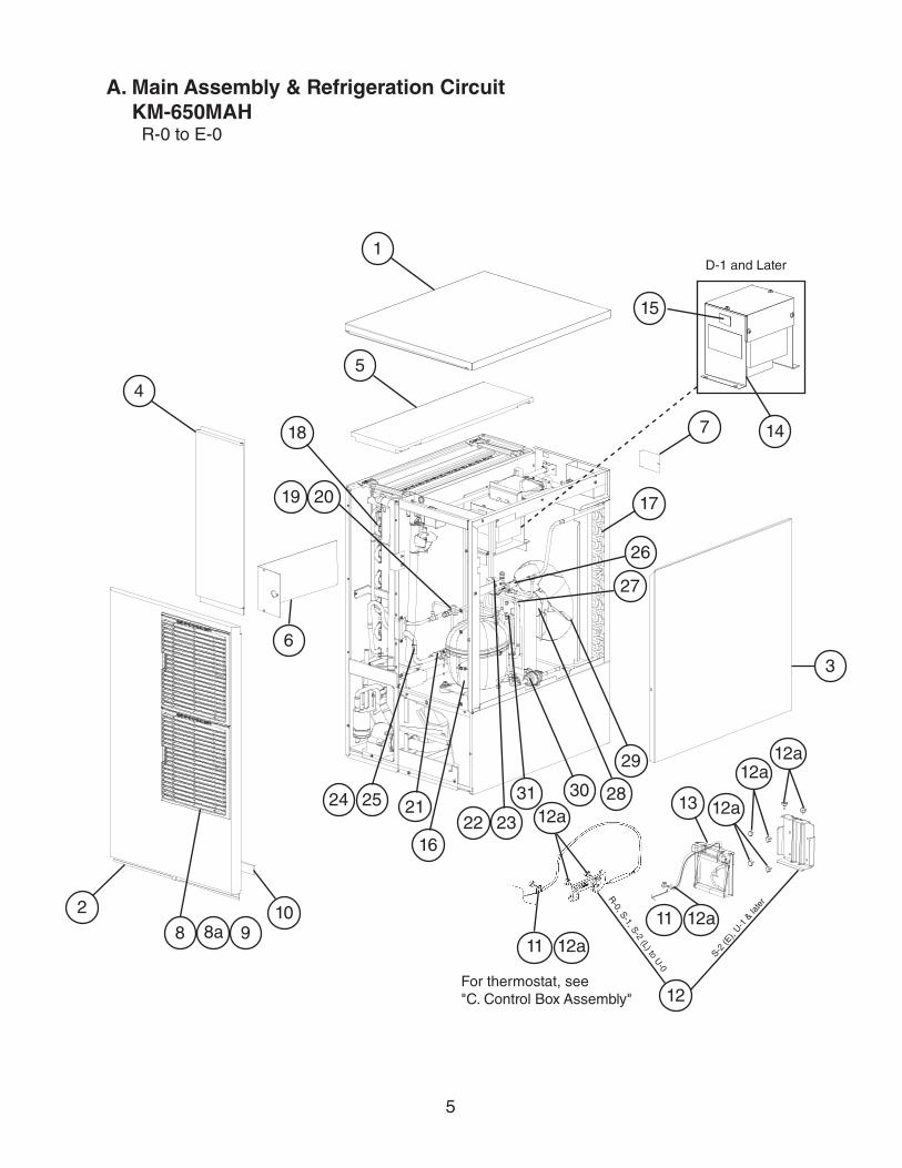
A. Main Assembly & Refrigeration CircuitKM-650MAH
R-0 to E-0
For thermostat, see "C. Control Box Assembly"
1
7
2
D-1 and Later
54
6
3
12
13
16
17
18
19 20
22 232124 25
29
27
26
2830
8 8a 9
12a12a
10
3112a
11 12a
11 12a
15
14
12a
R-0, S-1, S-2 (L) to U
-0
S-2 (E
), U-1
& la
ter
6
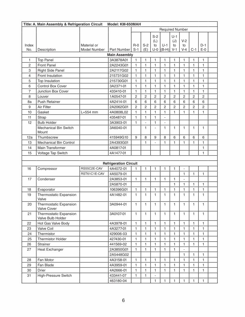
Title: A. Main Assembly & Refrigeration Circuit Model: KM-650MAH
Index No. Description
Material or Model Number Part Number
Required Number
R-0 S-1
S-2 (E)
S-2 (L)to
U-0U-1
(B-H)
U-1(J)to
V-1
V-2to
V-4 C-1D-1E-0
Main Assembly1 Top Panel 3A3878A01 1 1 1 1 1 1 1 1
2 Front Panel 2A2243G01 1 1 1 1 1 1 1 1
3 Right Side Panel 2A2117G02 1 1 1 1 1 1 1 1
4 Front Insulation 215731G02 1 1 1 1 1 1 1 1
5 Top Insulation 215730G01 1 1 1 1 1 1 1 1
6 Control Box Cover 3A2371-01 1 1 1 1 1 1 1 1
7 Junction Box Cover 433410-01 1 1 1 1 1 1 1 1
8 Louver 1A0547-01 2 2 2 2 2 2 2 2
8a Push Retainer 4A2414-01 6 6 6 6 6 6 6 6
9 Air Filter 2A2062G01 2 2 2 2 2 2 2 2
10 Gasket L=554 mm 4A0808L02 1 1 1 1 1 1 1 1
11 Strap 435487-01 1 1 1 -
12 Bulb Holder 3A3903-01 1 - 1 -
Mechanical Bin Switch Mount
3A6040-01 1 - 1 1 1 1 1
12a Thumbscrew 415949G10 9 8 9 8 6 6 6 6
13 Mechanical Bin Control 2A4393G01 1 - 1 1 1 1 1
14 Main Transformer 4A0817-01 1
15 Voltage Tap Switch 4A1477-01 1
Refrigeration Circuit16 Compressor RS55C2E-CAV 4A4072-01 1 1 1 1 1 -
RST61C1E-CAV 4A5079-01 1 1 1
17 Condenser 2A3853-01 1 1 1 1 1 -
2A5870-01 1 1 1 1
18 Evaporator 106396G01 1 1 1 1 1 1 1 1
19 Thermostatic Expansion Valve
4A1482-01 1 1 1 1 1 1 1 1
20 Thermostatic Expansion Valve Cover
3A0944-01 1 1 1 1 1 1 1 1
21 Thermostatic Expansion Valve Bulb Holder
3A0107-01 1 1 1 1 1 1 1 1
22 Hot Gas Valve Body 4A3978-01 1 1 1 1 1 1 1 1
23 Valve Coil 4A3277-01 1 1 1 1 1 1 1 1
24 Thermistor 429006-03 1 1 1 1 1 1 1 1
25 Thermistor Holder 427430-01 1 1 1 1 1 1 1 1
26 Strainer 441569-02 1 1 1 1 1 1 1 1
27 Heat Exchanger 2A3850G01 1 1 1 1 1 -
2A5448G02 1 1 1
28 Fan Motor 4A3158-01 1 1 1 1 1 1 1 1
29 Fan Blade 4A3959-01 1 1 1 1 1 1 1 1
30 Drier 4A2666-01 1 1 1 1 1 1 1 1
31 High-Pressure Switch 433441-07 1 1 -
463180-04 1 1 1 1 1 1
7
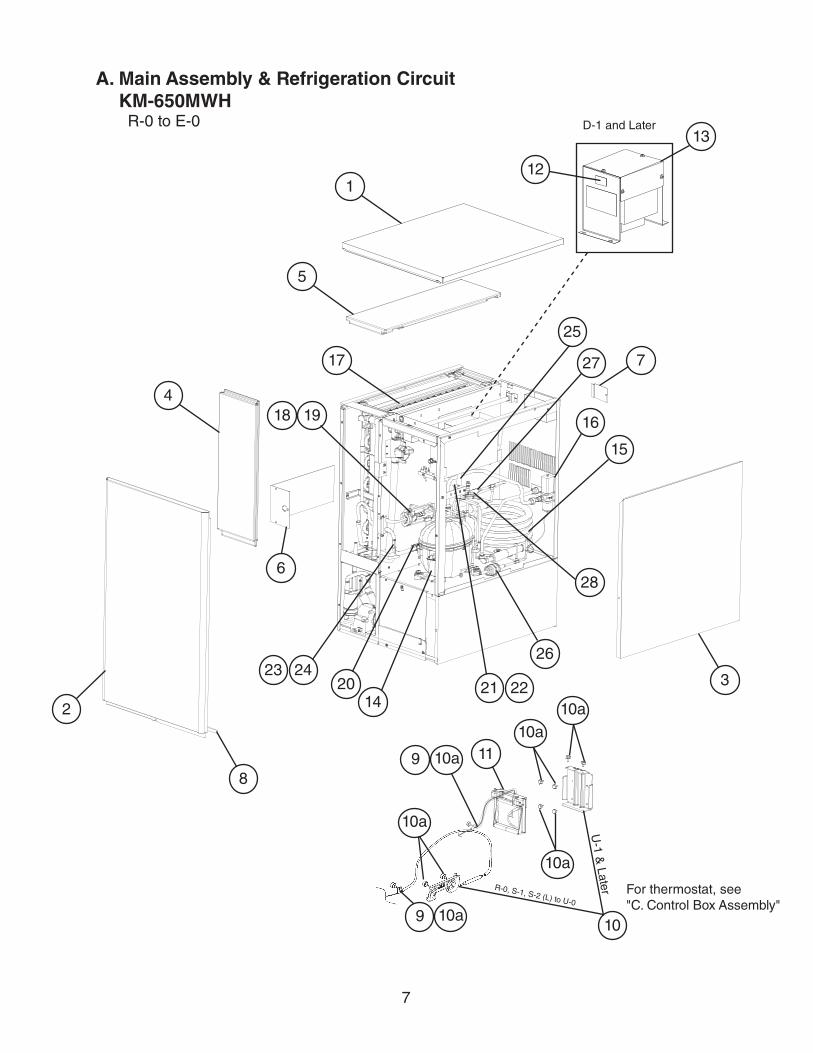
A. Main Assembly & Refrigeration CircuitKM-650MWH
R-0 to E-0
For thermostat, see "C. Control Box Assembly"
1
7
2
15
U-1 &
Later
8
5
4
6
3
10
11
14
16
17
18 19
21 222023 24
27
25
26
28
10a10a
10a
9
10a
13
12
D-1 and Later
9 10a
10a
R-0, S-1, S-2 (L) to U-0
8
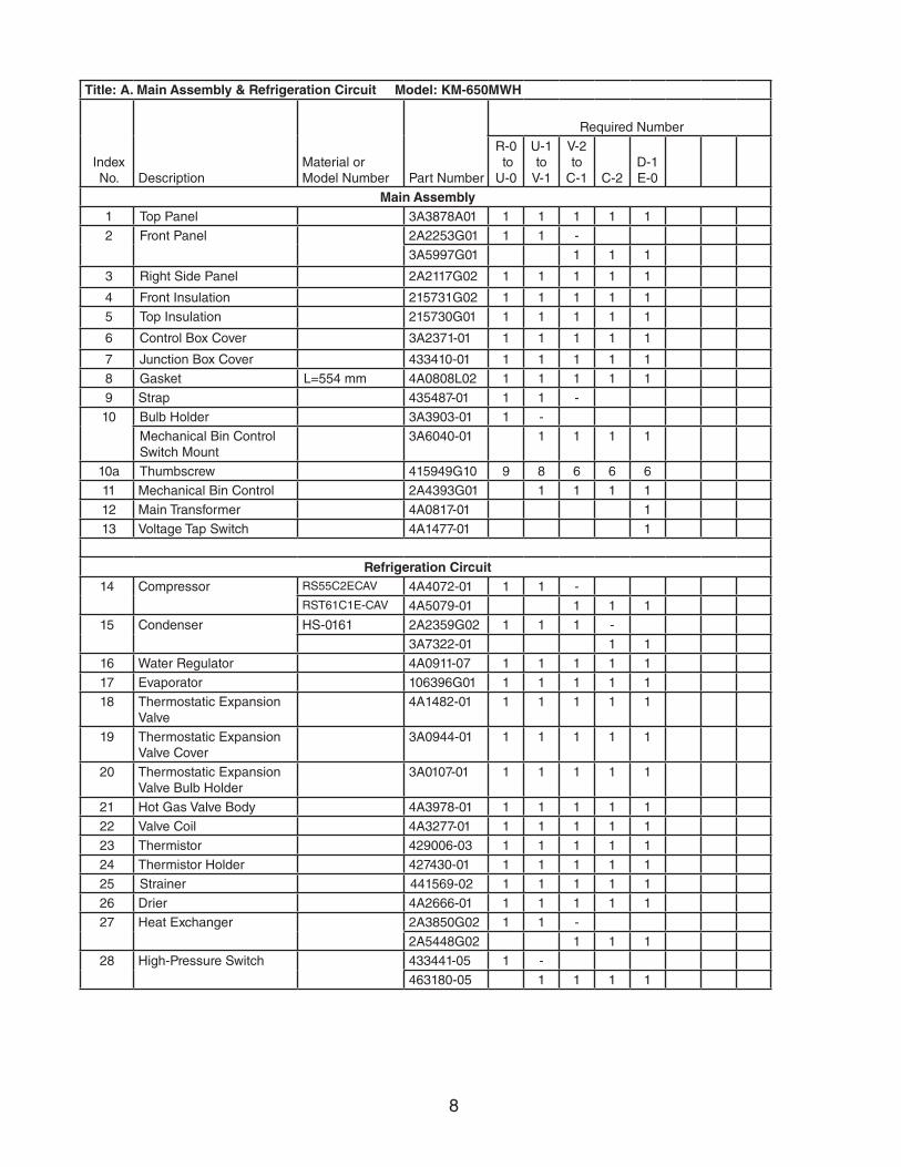
Title: A. Main Assembly & Refrigeration Circuit Model: KM-650MWH
Index No. Description
Material or Model Number Part Number
Required Number
R-0 to U-0
U-1to
V-1
V-2 to
C-1 C-2 D-1E-0
Main Assembly1 Top Panel 3A3878A01 1 1 1 1 1
2 Front Panel 2A2253G01 1 1 -
3A5997G01 1 1 1
3 Right Side Panel 2A2117G02 1 1 1 1 1
4 Front Insulation 215731G02 1 1 1 1 1
5 Top Insulation 215730G01 1 1 1 1 1
6 Control Box Cover 3A2371-01 1 1 1 1 1
7 Junction Box Cover 433410-01 1 1 1 1 1
8 Gasket L=554 mm 4A0808L02 1 1 1 1 1
9 Strap 435487-01 1 1 -
10 Bulb Holder 3A3903-01 1 -
Mechanical Bin Control Switch Mount
3A6040-01 1 1 1 1
10a Thumbscrew 415949G10 9 8 6 6 6
11 Mechanical Bin Control 2A4393G01 1 1 1 1
12 Main Transformer 4A0817-01 1
13 Voltage Tap Switch 4A1477-01 1
Refrigeration Circuit14 Compressor RS55C2ECAV 4A4072-01 1 1 -
RST61C1E-CAV 4A5079-01 1 1 1
15 Condenser HS-0161 2A2359G02 1 1 1 -
3A7322-01 1 1
16 Water Regulator 4A0911-07 1 1 1 1 1
17 Evaporator 106396G01 1 1 1 1 1
18 Thermostatic Expansion Valve
4A1482-01 1 1 1 1 1
19 Thermostatic Expansion Valve Cover
3A0944-01 1 1 1 1 1
20 Thermostatic Expansion Valve Bulb Holder
3A0107-01 1 1 1 1 1
21 Hot Gas Valve Body 4A3978-01 1 1 1 1 1
22 Valve Coil 4A3277-01 1 1 1 1 1
23 Thermistor 429006-03 1 1 1 1 1
24 Thermistor Holder 427430-01 1 1 1 1 1
25 Strainer 441569-02 1 1 1 1 1
26 Drier 4A2666-01 1 1 1 1 1
27 Heat Exchanger 2A3850G02 1 1 -
2A5448G02 1 1 1
28 High-Pressure Switch 433441-05 1 -
463180-05 1 1 1 1
9
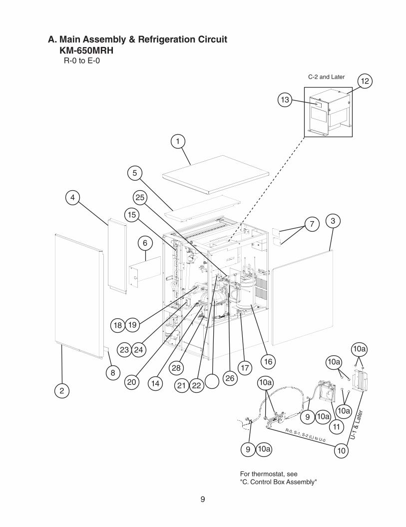
A. Main Assembly & Refrigeration CircuitKM-650MRH
R-0 to E-0
6
2
5
4
8
3
11
10
U-1
& L
ater
1
7
14
1617
1918
15
21 22
25
2620
28
23 24
For thermostat, see "C. Control Box Assembly"
10a
10a
10a
10a
13
12C-2 and Later
9 10a
9 10a
R-0, S-1, S-2 (L) to U-0
10
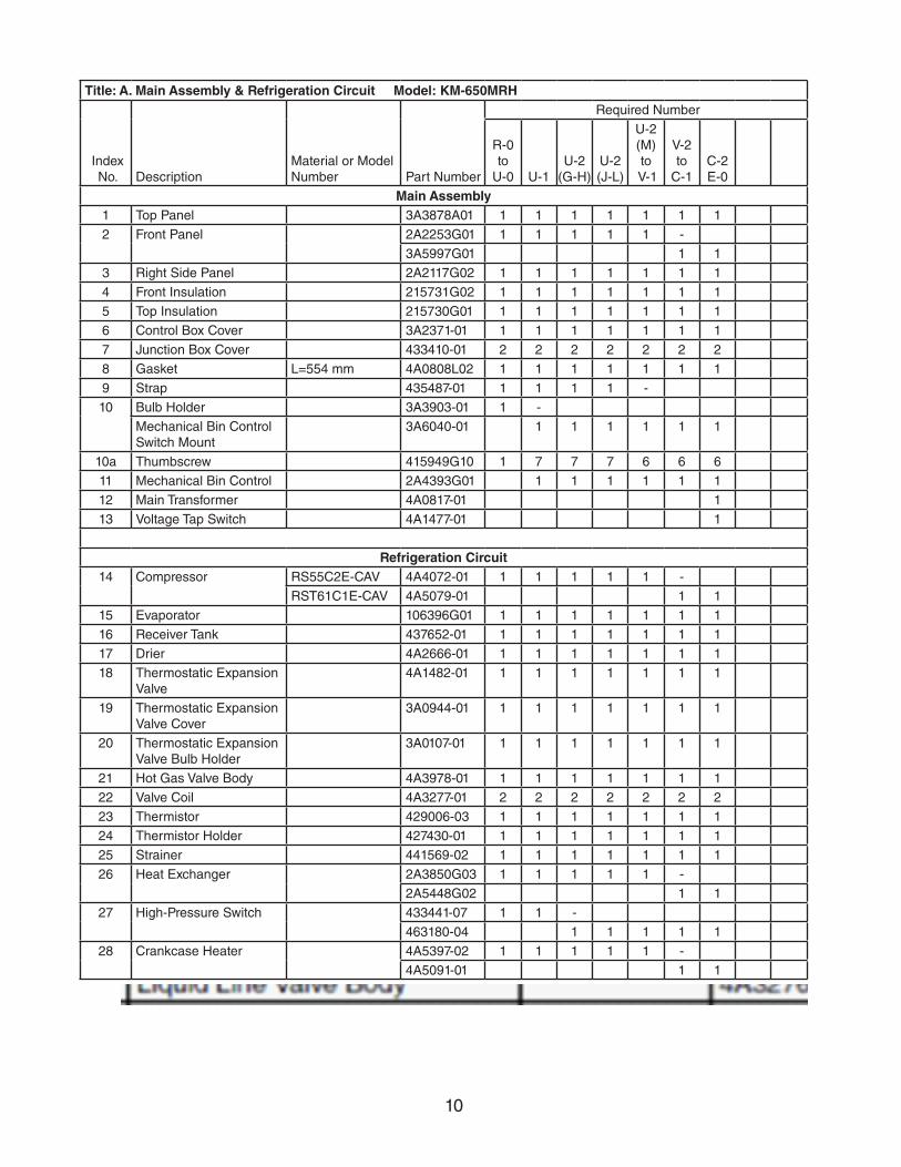
Title: A. Main Assembly & Refrigeration Circuit Model: KM-650MRH
Index No. Description
Material or Model Number Part Number
Required Number
R-0to
U-0 U-1U-2
(G-H)U-2 (J-L)
U-2(M)to
V-1
V-2 to
C-1C-2 E-0
Main Assembly1 Top Panel 3A3878A01 1 1 1 1 1 1 1
2 Front Panel 2A2253G01 1 1 1 1 1 -
3A5997G01 1 1
3 Right Side Panel 2A2117G02 1 1 1 1 1 1 1
4 Front Insulation 215731G02 1 1 1 1 1 1 1
5 Top Insulation 215730G01 1 1 1 1 1 1 1
6 Control Box Cover 3A2371-01 1 1 1 1 1 1 1
7 Junction Box Cover 433410-01 2 2 2 2 2 2 2
8 Gasket L=554 mm 4A0808L02 1 1 1 1 1 1 1
9 Strap 435487-01 1 1 1 1 -
10 Bulb Holder 3A3903-01 1 -
Mechanical Bin Control Switch Mount
3A6040-01 1 1 1 1 1 1
10a Thumbscrew 415949G10 1 7 7 7 6 6 6
11 Mechanical Bin Control 2A4393G01 1 1 1 1 1 1
12 Main Transformer 4A0817-01 1
13 Voltage Tap Switch 4A1477-01 1
Refrigeration Circuit14 Compressor RS55C2E-CAV 4A4072-01 1 1 1 1 1 -
RST61C1E-CAV 4A5079-01 1 1
15 Evaporator 106396G01 1 1 1 1 1 1 1
16 Receiver Tank 437652-01 1 1 1 1 1 1 1
17 Drier 4A2666-01 1 1 1 1 1 1 1
18 Thermostatic Expansion Valve
4A1482-01 1 1 1 1 1 1 1
19 Thermostatic Expansion Valve Cover
3A0944-01 1 1 1 1 1 1 1
20 Thermostatic Expansion Valve Bulb Holder
3A0107-01 1 1 1 1 1 1 1
21 Hot Gas Valve Body 4A3978-01 1 1 1 1 1 1 1
22 Valve Coil 4A3277-01 2 2 2 2 2 2 2
23 Thermistor 429006-03 1 1 1 1 1 1 1
24 Thermistor Holder 427430-01 1 1 1 1 1 1 1
25 Strainer 441569-02 1 1 1 1 1 1 1
26 Heat Exchanger 2A3850G03 1 1 1 1 1 -
2A5448G02 1 1
27 High-Pressure Switch 433441-07 1 1 -
463180-04 1 1 1 1 1
28 Crankcase Heater 4A5397-02 1 1 1 1 1 -
4A5091-01 1 1
11
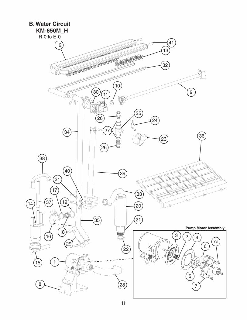
B. Water CircuitKM-650M_H
R-0 to E-0
8 28
22
21
20
23
29
1618
19
33
37
38
14
15
32
1213
41
30 11
109
39
36
2625
3 2 4
5
6
7
7a
Pump Motor Assembly
1
34
17
40
24
31
26
27
35
12
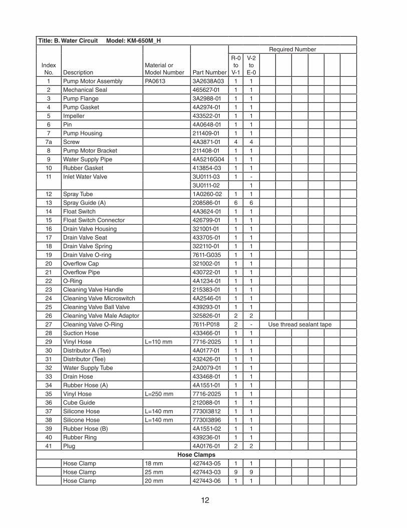
Title: B. Water Circuit Model: KM-650M_H
Index No. Description
Material or Model Number Part Number
Required Number
R-0 to
V-1
V-2 to
E-0
1 Pump Motor Assembly PA0613 3A2638A03 1 1
2 Mechanical Seal 465627-01 1 1
3 Pump Flange 3A2988-01 1 1
4 Pump Gasket 4A2974-01 1 1
5 Impeller 433522-01 1 1
6 Pin 4A0648-01 1 1
7 Pump Housing 211409-01 1 1
7a Screw 4A3871-01 4 4
8 Pump Motor Bracket 211408-01 1 1
9 Water Supply Pipe 4A5216G04 1 1
10 Rubber Gasket 413854-03 1 1
11 Inlet Water Valve 3U0111-03 1 -
3U0111-02 1
12 Spray Tube 1A0260-02 1 1
13 Spray Guide (A) 208586-01 6 6
14 Float Switch 4A3624-01 1 1
15 Float Switch Connector 426799-01 1 1
16 Drain Valve Housing 321001-01 1 1
17 Drain Valve Seat 433705-01 1 1
18 Drain Valve Spring 322110-01 1 1
19 Drain Valve O-ring 7611-G035 1 1
20 Overflow Cap 321002-01 1 1
21 Overflow Pipe 430722-01 1 1
22 O-Ring 4A1234-01 1 1
23 Cleaning Valve Handle 215383-01 1 1
24 Cleaning Valve Microswitch 4A2546-01 1 1
25 Cleaning Valve Ball Valve 439293-01 1 1
26 Cleaning Valve Male Adaptor 325826-01 2 2
27 Cleaning Valve O-Ring 7611-P018 2 - Use thread sealant tape
28 Suction Hose 433466-01 1 1
29 Vinyl Hose L=110 mm 7716-2025 1 1
30 Distributor A (Tee) 4A0177-01 1 1
31 Distributor (Tee) 432426-01 1 1
32 Water Supply Tube 2A0079-01 1 1
33 Drain Hose 433468-01 1 1
34 Rubber Hose (A) 4A1551-01 1 1
35 Vinyl Hose L=250 mm 7716-2025 1 1
36 Cube Guide 212088-01 1 1
37 Silicone Hose L=140 mm 7730I3812 1 1
38 Silicone Hose L=140 mm 7730I3896 1 1
39 Rubber Hose (B) 4A1551-02 1 1
40 Rubber Ring 439236-01 1 1
41 Plug 4A0176-01 2 2
Hose ClampsHose Clamp 18 mm 427443-05 1 1
Hose Clamp 25 mm 427443-03 9 9
Hose Clamp 20 mm 427443-06 1 1
13
1
2
3
5
7
8
10 11
4
6
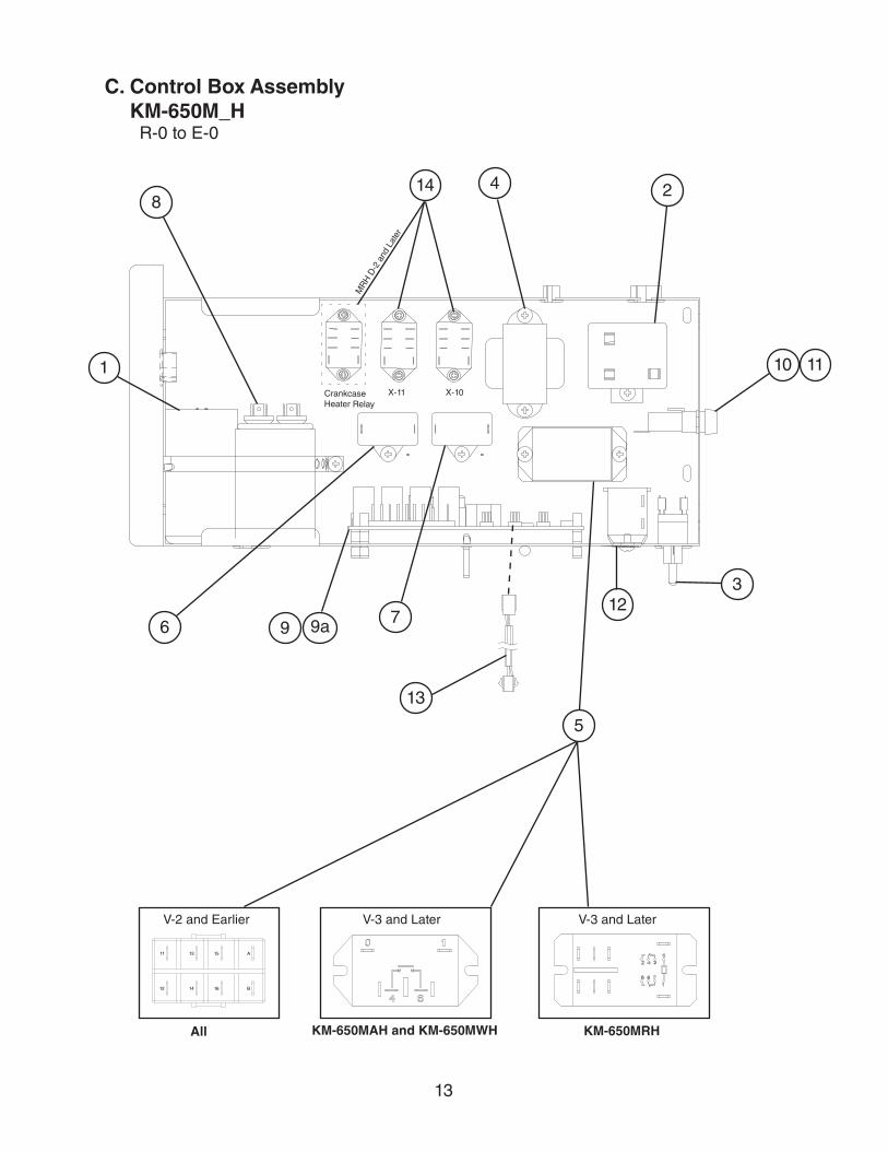
C. Control Box AssemblyKM-650M_H
R-0 to E-0
V-3 and Later
9
14
13
9a12
KM-650MRH
V-2 and Earlier
A
B
15
16
13
14
11
12
All
V-3 and Later
KM-650MAH and KM-650MWH
MR
H D
-2 a
nd L
ater
X-10X-11Crankcase Heater Relay
14
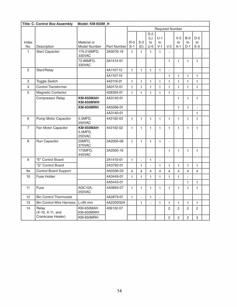
Title: C. Control Box Assembly Model: KM-650M_H
Index No. Description
Material or Model Number Part Number
Required Number
R-0 S-1
S-2 (E)
S-2 (L)to
U-0
U-1to
V-1 V-2
V-3to
A-1
B-0 to
D-1
D-2 to
E-0
1 Start Capacitor 175-216MFD, 330VAC
3A0076-19 1 1 1 1 -
72-86MFD, 330VAC
3A1414-01 1 1 1 1
2 Start/Relay 4A1107-12 1 1 1 1 -
4A1107-19 1 1 1 1
3 Toggle Switch 443119-01 1 1 1 1 1 1 1 1
4 Control Transformer 3A0172-01 1 1 1 1 1 1 1 1
5 Magnetic Contactor 428393-01 1 1 1 1 1 -
Compressor Relay KM-650MAHKM-650MWH
4A3140-01 1 1 1
KM-650MRH 4A5096-01 1 1 -
4A3140-01 1
6 Pump Motor Capacitor 5.5MFD,250VAC
443192-03 1 1 1 1 1 1 1 1
7 Fan Motor Capacitor KM-650MAH5.0MFD,250VAC
443192-02 1 1 1 1 1 1 1 1
8 Run Capacitor 25MFD,370VAC
3A2005-06 1 1 1 1 -
17.5MFD, 440VAC
3A2005-16 1 1 1 1
9 "E" Control Board 2A1410-01 1 - 1 -
"G" Control Board 2A3792-01 1 - 1 1 1 1 1
9a Control Board Support 4A0336-03 4 4 4 4 4 4 4 4
10 Fuse Holder 4A3449-01 1 1 1 1 1 1 -
4A5443-01 1 1
11 Fuse AGC10A, 250VAC
4A0893-07 1 1 1 1 1 1 1 1
12 Bin Control Thermostat 4A2879-01 1 - 1 -
13 Bin Control Wire Harness L=90 mm 4A2200G04 1 - 1 1 1 1 1
14 Relay (X-10, X-11, and Crankcase Heater)
KM-650MAHKM-650MWH
406132-07 2 2 2 2
KM-650MRH 2 2 2 3
15
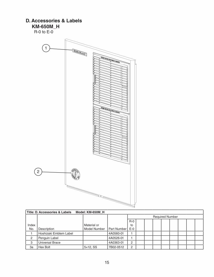
D. Accessories & LabelsKM-650M_H
R-0 to E-0
1
2
Title: D. Accessories & Labels Model: KM-650M_H
Index No. Description
Material or Model Number Part Number
Required Number
R-0to
E-0
1 Hoshizaki Emblem Label 4A0560-01 1
2 Penguin Label 4A0526-01 1
3 Universal Brace 4A0363-01 2
3a Hex Bolt 5×12, SS 7B02-0512 2