klein technical manual - mtb- · pdf file3 mountain frame geometry 1994 - 1996 model top top...
TRANSCRIPT

1
Klein Technical ManualThis manual covers all Klein models to August 1996
© 2 0 0 1 K l e i n B i c y c l e C o r p o r a t i o n . A l l r i g h t s r e s e r v e d . T h e K l e i n l o g o i s a r e g i s t e r e d l o g o o f K l e i n B i c y c l e c o r p o r a t i o n .
2
Table of Contents....................................................................................................... 1
Frame Mountain Geometry........................................................................................ 3 - 4 Road Geometry................................................................................................ 5 - 6 Weights........................................................................................................... 7 Details..............................................................................................................8 - 9 Seat Tube Lengths........................................................................................... 10 Tubing...............................................................................................................11 Sizing................................................................................................................12Forks Mountain..........................................................................................................13 Road................................................................................................................. 14 Accessorie....................................................................................................... 15 MC Bar Stem.................................................................................................. 16 Airhead Mountain............................................................................................17 Airhead Road................................................................................................... 18 Road Bar / Stem.............................................................................................. 19 Zip Grip............................................................................................................ 20 Chain Control Device...................................................................................... 21-22 J: Bottom Bracket Specifications................................................................... 23 Bottom Bracket Settings Mountain................................................................ 24 Bottom Bracket Settings Road ...................................................................... 25Tools Bottom BracketTool......................................................................................... 26-29 Headset Tool................................................................................................... 30-34Misc. Touch-Up Paint ............................................................................................... 35-36 Decals.............................................................................................................. 37 Rack Application ............................................................................................. 38 Riv-Nuts........................................................................................................... 39 SIS Update....................................................................................................... 40 Packaging......................................................................................................... 41
Klein Technical ManualThis manual covers all Klein models to August 1996
This manual covers all Klein models to August 1996

3
MOUNTAIN FRAME GEOMETRY1994 - 1996
MODEL Top Top Top Seat Head Chain BB Wheel Head Steerer Fork SIZE Tube Tube Tube Tube Tube Stay Height Base Tube Tube Rake Height Length Angle Angle Angle Length Length Length (cm / inch) (inch) (cm) (inch) (inch) (inch) (mm) (mm) (inch)
ADROIT / ATTITUDE
46 / 18 27.42 55.9 15.4 73.2 71 16.4 11.4 40.07 92 178 1.38
48 / 19 28.21 57.9 10.5 73.2 71.5 16.4 11.5 40.67 92 178 1.38
53 / 20 29.62 59.4 8.2 73.2 72 16.4 11.7 41.21 119 205 1.38
55 / 21 30.66 60.2 8.4 73.2 72.2 16.4 11.8 41.64 147 233 1.5
57 / 22 31.76 61.1 8 73.2 72.2 16.4 11.9 42.04 178 264 1.5
PULSE II
46 / 18 27.78 55.4 17.2 73.2 71 16.4 11.4 40.07 95 n/a 1.38
48 / 19 28.58 57.4 12.5 73.2 71.5 16.4 11.5 40.67 95 n/a 1.38
53 / 20 29.62 59.4 8.27 73.2 72 16.4 11.7 41.21 101 n/a 1.38
55 / 21 30.68 59.9 8.47 73.2 72.2 16.4 11.8 41.64 129 n/a 1.5
57 / 22 31.78 61.1 8.07 73.2 72.2 16.4 11.9 42.04 158 n/a 1.5
PULSE COMP
46 / 18 27.78 55.4 17.2 73.2 71 16.4 11.4 40.07 95 n/a 1.38
48 / 19 28.58 57.4 12.5 73.2 71.5 16.4 11.5 40.67 95 n/a 1.38
53 / 20 29.62 59.4 8.27 73.2 72 16.4 11.7 41.21 101 n/a 1.38
55 / 21 30.68 59.9 8.47 73.2 72.2 16.4 11.8 41.64 129 n/a 1.5
57 / 22 31.78 61.1 8.07 73.2 72.2 16.4 11.9 42.04 158 n/a 1.5
This manual covers all Klein models to August 1996

4
ROAD FRAME GEOMETRYDiscontinued Models
MODEL Top Top Top Seat Head Chain BB Wheel Head Steerer Fork SIZE Tube Tube Tube Tube Tube Stay Height Base Tube Tube Rake Height Length Angle Angle Angle Length Length Length (cm / inch) (inch) (cm) (inch) (inch) (inch) (mm) (mm) (inch)
PERFORMANCE 52 / 20.5 30.1 54.2 0 74 72 18 10.2 40.7 90 130 1.75 54 / 21.3 31 55.2 0 74 72 18 10.3 41.1 114 154 1.75 56 / 22.0 31.8 56.2 0 74 72.5 18 10.4 41.2 133 173 1.5 58 / 22.8 32.7 57.2 0 74 72.5 18 10.5 41.6 157 197 1.5 60 / 23.6 33.6 58.2 0 74 72.5 18 10.6 42.2 180 220 1.5 62 / 24.4 24.4 59.2 0 74 72.5 18 10.7 42.6 200 240 1.5
KIRSTEN / PANACHE 47 / 18.5 27.3 51.3 14 74 71 16.77 10.1 38.4 80 120 2.0 50 / 19.7 27.3 51.3 14 74 71 16.77 10.1 38.4 103 143 2.0
CUSTOM STAGE / ADVANTAGE *46 / 18.1 27 51.2 0 74 72 16.5 9.6 38.2 63 103 1.5 *48 / 18.9 28 52.2 0 74 72 16.5 9.8 38.7 88 128 1.5 *50 / 19.7 29 53.2 0 74 72 16.5 10 39.2 115 195 1.5 52 / 20.5 30.1 54.2 0 74 72 18 10.2 40.7 90 130 1.75 54 / 21.3 31 55.2 0 74 72 18 10.3 41.1 114 154 1.75 56 / 22.0 31.8 56.2 0 74 72.5 18 10.4 41.2 133 173 1.5 58 / 22.8 32.7 57.2 0 74 72.5 18 10.5 41.6 157 197 1.5 60 / 23.6 33.6 58.2 0 74 72.5 18 10.6 42.2 180 220 1.5 62 / 24.4 34.4 59.2 0 74 72.5 18 10.7 42.6 202 242 1.5 64 / 25.2 35.2 60.2 0 74 72.5 18 10.8 43 223 263 1.5 66 / 26.0 36.1 61.2 0 74.5 72.5 18 10.8 43.6 246 286 1.5 68 / 26.8 36.8 62.2 0 74.5 72.5 18 10.8 44.1 269 309 1.5 70 / 27.6 37 63.2 0 74.5 72.5 18 10.8 44.5 285 325 1.5 * = 24” wheels
CUSTOM TEAM SUPER / CRITERIUM 51 / 20.1 29.8 53.5 0 74 73.5 16.3 10.5 38.1 90 130 1.5 53 / 20.9 30.6 54.7 0 74 73.5 16.3 10.6 38.6 109 149 1.5 55 / 21.7 31.5 55.9 0 74 73.5 16.3 10.7 39.1 133 173 1.5 57 / 22.4 32.4 57.1 0 74 74 16.3 10.8 39.4 153 193 1.5 59 / 23.2 33.2 58.3 0 74 74 16.3 10.9 40 179 219 1.5 61 / 24.0 34.1 59.5 0 74 74 16.3 11 40.4 200 240 1.5 63 / 24.8 34.8 60.7 0 74 74 16.3 11 40.9 219 259 1.5 65 / 25.6 35.6 61.9 0 74 74 16.3 11 41.4 240 280 1.5 68 / 26.8 36.7 63.7 0 74 74 16.3 11 42.1 268 308 1.5
This manual covers all Klein models to August 1996
5
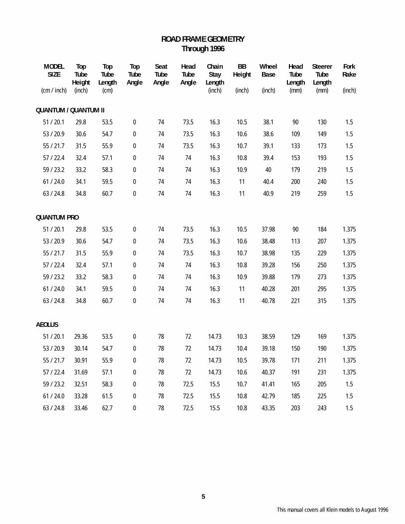
ROAD FRAME GEOMETRYThrough 1996
MODEL Top Top Top Seat Head Chain BB Wheel Head Steerer Fork SIZE Tube Tube Tube Tube Tube Stay Height Base Tube Tube Rake Height Length Angle Angle Angle Length Length Length (cm / inch) (inch) (cm) (inch) (inch) (inch) (mm) (mm) (inch)
QUANTUM / QUANTUM II
51 / 20.1 29.8 53.5 0 74 73.5 16.3 10.5 38.1 90 130 1.5
53 / 20.9 30.6 54.7 0 74 73.5 16.3 10.6 38.6 109 149 1.5
55 / 21.7 31.5 55.9 0 74 73.5 16.3 10.7 39.1 133 173 1.5
57 / 22.4 32.4 57.1 0 74 74 16.3 10.8 39.4 153 193 1.5
59 / 23.2 33.2 58.3 0 74 74 16.3 10.9 40 179 219 1.5
61 / 24.0 34.1 59.5 0 74 74 16.3 11 40.4 200 240 1.5
63 / 24.8 34.8 60.7 0 74 74 16.3 11 40.9 219 259 1.5
QUANTUM PRO
51 / 20.1 29.8 53.5 0 74 73.5 16.3 10.5 37.98 90 184 1.375
53 / 20.9 30.6 54.7 0 74 73.5 16.3 10.6 38.48 113 207 1.375
55 / 21.7 31.5 55.9 0 74 73.5 16.3 10.7 38.98 135 229 1.375
57 / 22.4 32.4 57.1 0 74 74 16.3 10.8 39.28 156 250 1.375
59 / 23.2 33.2 58.3 0 74 74 16.3 10.9 39.88 179 273 1.375
61 / 24.0 34.1 59.5 0 74 74 16.3 11 40.28 201 295 1.375
63 / 24.8 34.8 60.7 0 74 74 16.3 11 40.78 221 315 1.375
AEOLUS
51 / 20.1 29.36 53.5 0 78 72 14.73 10.3 38.59 129 169 1.375
53 / 20.9 30.14 54.7 0 78 72 14.73 10.4 39.18 150 190 1.375
55 / 21.7 30.91 55.9 0 78 72 14.73 10.5 39.78 171 211 1.375
57 / 22.4 31.69 57.1 0 78 72 14.73 10.6 40.37 191 231 1.375
59 / 23.2 32.51 58.3 0 78 72.5 15.5 10.7 41.41 165 205 1.5
61 / 24.0 33.28 61.5 0 78 72.5 15.5 10.8 42.79 185 225 1.5
63 / 24.8 33.46 62.7 0 78 72.5 15.5 10.8 43.35 203 243 1.5
This manual covers all Klein models to August 1996
6
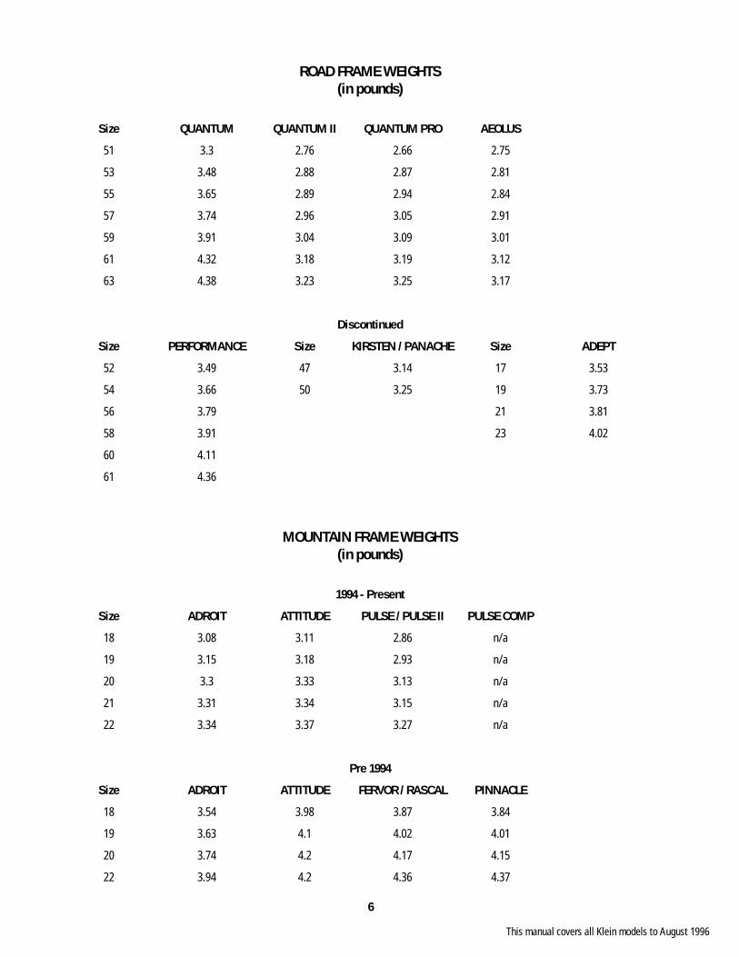
ROAD FRAME WEIGHTS(in pounds)
Size QUANTUM QUANTUM II QUANTUM PRO AEOLUS
51 3.3 2.76 2.66 2.75
53 3.48 2.88 2.87 2.81
55 3.65 2.89 2.94 2.84
57 3.74 2.96 3.05 2.91
59 3.91 3.04 3.09 3.01
61 4.32 3.18 3.19 3.12
63 4.38 3.23 3.25 3.17
Discontinued
Size PERFORMANCE Size KIRSTEN / PANACHE Size ADEPT
52 3.49 47 3.14 17 3.53
54 3.66 50 3.25 19 3.73
56 3.79 21 3.81
58 3.91 23 4.02
60 4.11
61 4.36
MOUNTAIN FRAME WEIGHTS(in pounds)
1994 - Present
Size ADROIT ATTITUDE PULSE / PULSE II PULSE COMP
18 3.08 3.11 2.86 n/a
19 3.15 3.18 2.93 n/a
20 3.3 3.33 3.13 n/a
21 3.31 3.34 3.15 n/a
22 3.34 3.37 3.27 n/a
Pre 1994
Size ADROIT ATTITUDE FERVOR / RASCAL PINNACLE
18 3.54 3.98 3.87 3.84
19 3.63 4.1 4.02 4.01
20 3.74 4.2 4.17 4.15
22 3.94 4.2 4.36 4.37
This manual covers all Klein models to August 1996
7
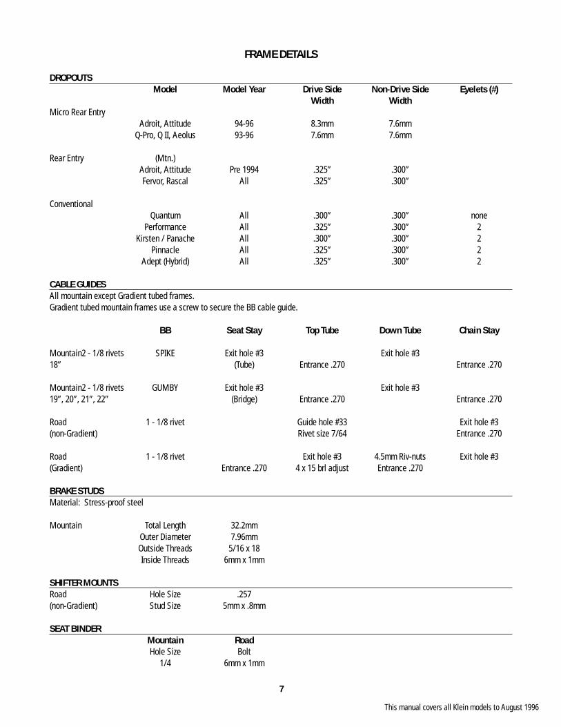
FRAME DETAILS
DROPOUTS Model Model Year Drive Side Non-Drive Side Eyelets (#) Width WidthMicro Rear Entry Adroit, Attitude 94-96 8.3mm 7.6mm Q-Pro, Q II, Aeolus 93-96 7.6mm 7.6mm
Rear Entry (Mtn.) Adroit, Attitude Pre 1994 .325” .300” Fervor, Rascal All .325” .300”
Conventional Quantum All .300” .300” none Performance All .325” .300” 2 Kirsten / Panache All .300” .300” 2 Pinnacle All .325” .300” 2 Adept (Hybrid) All .325” .300” 2
CABLE GUIDESAll mountain except Gradient tubed frames.Gradient tubed mountain frames use a screw to secure the BB cable guide.
BB Seat Stay Top Tube Down Tube Chain Stay
Mountain 2 - 1/8 rivets SPIKE Exit hole #3 Exit hole #318” (Tube) Entrance .270 Entrance .270
Mountain 2 - 1/8 rivets GUMBY Exit hole #3 Exit hole #319”, 20”, 21”, 22” (Bridge) Entrance .270 Entrance .270
Road 1 - 1/8 rivet Guide hole #33 Exit hole #3(non-Gradient) Rivet size 7/64 Entrance .270
Road 1 - 1/8 rivet Exit hole #3 4.5mm Riv-nuts Exit hole #3(Gradient) Entrance .270 4 x 15 brl adjust Entrance .270
BRAKE STUDSMaterial: Stress-proof steel
Mountain Total Length 32.2mm Outer Diameter 7.96mm Outside Threads 5/16 x 18 Inside Threads 6mm x 1mm
SHIFTER MOUNTSRoad Hole Size .257(non-Gradient) Stud Size 5mm x .8mm
SEAT BINDER Mountain Road Hole Size Bolt 1/4 6mm x 1mm
This manual covers all Klein models to August 1996

8
FRAME DETAILS (cont.)
RACK MOUNTSModel Size Total LocationPerformance 4 D.O. (2) S.S. (2)Adept 17 2 D.O. (2) S.S. (*)Adept Frame 19, 21, 23 4 D.O. (2) S.S. (2)Adept Fork Low-rider 4 D.O. (2) Blade (2)Pinnacle 18, 19 2 D.O. (2) S.S. (*)Pinnacle 20, 22 4 D.O. (2) S.S. (2)
Threads 5mm x 0.08 Size 5mm x 16mm*use seat binder bolt for top mount
FENDER MOUNTSModel Total LocationPerformance 4 Dropout S.S. Bridge C.S. BridgeAdept 4 Dropout S.S. Bridge C.S. GussetPinnacle 3 Dropout S.S. Bridge
Threads 5mm x 0.08 Size 5mm x 16mm
WATERBOTTLE MOUNTSModel Size Total LocationQuantum, Performance 2 Seat tube & Down tubeQuantum II, Quantum Pro 2 Seat tube & Down tubePanache 2 Down tube (top & bottom)
Mountain 18 2 Down tube (top & bottom) 19 3 Down tube (top & bottom), Seat tube 20 3 Down tube (top & bottom), Seat tube 21 4 Down tube [top (1), below (2), seat tube (1)] 22 4 Down tube [top (1), below (2), seat tube (1)]
Adept (Hybrid) 17 2 Down tube (top & bottom) 19, 21 2 Seat tube & Down tube 23 3 Down tube [top (2)], Seat tube (1)
Threads 5mm x 0.08 Size 5mm x 16mm
This manual covers all Klein models to August 1996
9
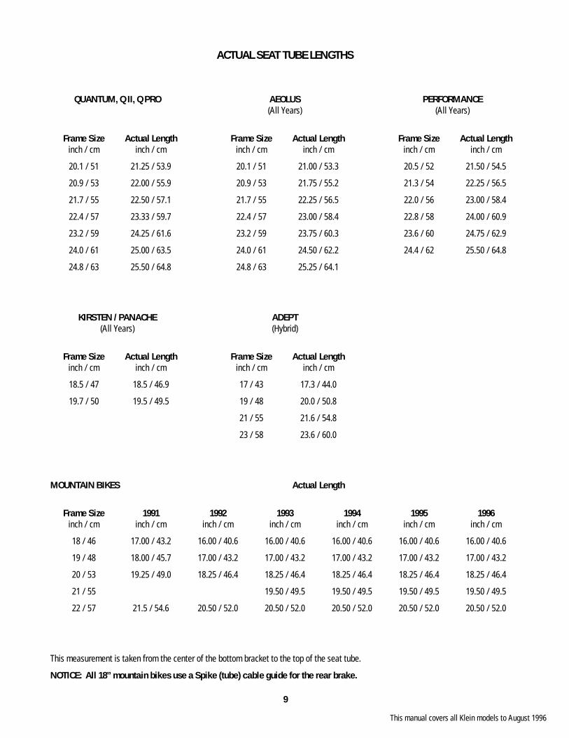
ACTUAL SEAT TUBE LENGTHS
QUANTUM, Q II, Q PRO AEOLUS PERFORMANCE (All Years) (All Years)
Frame Size Actual Length Frame Size Actual Length Frame Size Actual Length inch / cm inch / cm inch / cm inch / cm inch / cm inch / cm
20.1 / 51 21.25 / 53.9 20.1 / 51 21.00 / 53.3 20.5 / 52 21.50 / 54.5
20.9 / 53 22.00 / 55.9 20.9 / 53 21.75 / 55.2 21.3 / 54 22.25 / 56.5
21.7 / 55 22.50 / 57.1 21.7 / 55 22.25 / 56.5 22.0 / 56 23.00 / 58.4
22.4 / 57 23.33 / 59.7 22.4 / 57 23.00 / 58.4 22.8 / 58 24.00 / 60.9
23.2 / 59 24.25 / 61.6 23.2 / 59 23.75 / 60.3 23.6 / 60 24.75 / 62.9
24.0 / 61 25.00 / 63.5 24.0 / 61 24.50 / 62.2 24.4 / 62 25.50 / 64.8
24.8 / 63 25.50 / 64.8 24.8 / 63 25.25 / 64.1
KIRSTEN / PANACHE ADEPT (All Years) (Hybrid)
Frame Size Actual Length Frame Size Actual Length inch / cm inch / cm inch / cm inch / cm
18.5 / 47 18.5 / 46.9 17 / 43 17.3 / 44.0
19.7 / 50 19.5 / 49.5 19 / 48 20.0 / 50.8
21 / 55 21.6 / 54.8
23 / 58 23.6 / 60.0
MOUNTAIN BIKES Actual Length
Frame Size 1991 1992 1993 1994 1995 1996 inch / cm inch / cm inch / cm inch / cm inch / cm inch / cm inch / cm
18 / 46 17.00 / 43.2 16.00 / 40.6 16.00 / 40.6 16.00 / 40.6 16.00 / 40.6 16.00 / 40.6
19 / 48 18.00 / 45.7 17.00 / 43.2 17.00 / 43.2 17.00 / 43.2 17.00 / 43.2 17.00 / 43.2
20 / 53 19.25 / 49.0 18.25 / 46.4 18.25 / 46.4 18.25 / 46.4 18.25 / 46.4 18.25 / 46.4
21 / 55 19.50 / 49.5 19.50 / 49.5 19.50 / 49.5 19.50 / 49.5
22 / 57 21.5 / 54.6 20.50 / 52.0 20.50 / 52.0 20.50 / 52.0 20.50 / 52.0 20.50 / 52.0
This measurement is taken from the center of the bottom bracket to the top of the seat tube.
NOTICE: All 18” mountain bikes use a Spike (tube) cable guide for the rear brake.
This manual covers all Klein models to August 1996
10
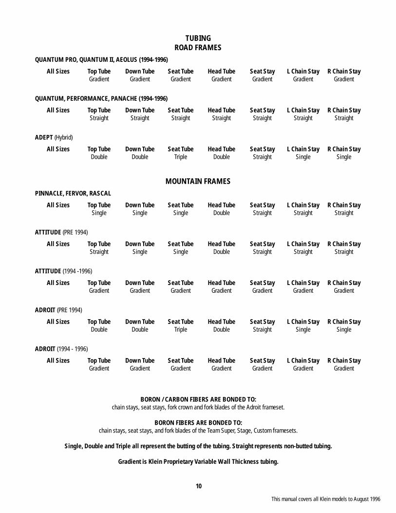
TUBINGROAD FRAMES
QUANTUM PRO, QUANTUM II, AEOLUS (1994-1996)
All Sizes Top Tube Down Tube Seat Tube Head Tube Seat Stay L Chain Stay R Chain Stay Gradient Gradient Gradient Gradient Gradient Gradient Gradient
QUANTUM, PERFORMANCE, PANACHE (1994-1996)
All Sizes Top Tube Down Tube Seat Tube Head Tube Seat Stay L Chain Stay R Chain Stay Straight Straight Straight Straight Straight Straight Straight
ADEPT (Hybrid)
All Sizes Top Tube Down Tube Seat Tube Head Tube Seat Stay L Chain Stay R Chain Stay Double Double Triple Double Straight Single Single
MOUNTAIN FRAMESPINNACLE, FERVOR, RASCAL
All Sizes Top Tube Down Tube Seat Tube Head Tube Seat Stay L Chain Stay R Chain Stay Single Single Single Double Straight Straight Straight
ATTITUDE (PRE 1994)
All Sizes Top Tube Down Tube Seat Tube Head Tube Seat Stay L Chain Stay R Chain Stay Straight Single Single Double Straight Straight Straight
ATTITUDE (1994 -1996)
All Sizes Top Tube Down Tube Seat Tube Head Tube Seat Stay L Chain Stay R Chain Stay Gradient Gradient Gradient Gradient Gradient Gradient Gradient
ADROIT (PRE 1994)
All Sizes Top Tube Down Tube Seat Tube Head Tube Seat Stay L Chain Stay R Chain Stay Double Double Triple Double Straight Single Single
ADROIT (1994 - 1996)
All Sizes Top Tube Down Tube Seat Tube Head Tube Seat Stay L Chain Stay R Chain Stay Gradient Gradient Gradient Gradient Gradient Gradient Gradient
BORON / CARBON FIBERS ARE BONDED TO:chain stays, seat stays, fork crown and fork blades of the Adroit frameset.
BORON FIBERS ARE BONDED TO:chain stays, seat stays, and fork blades of the Team Super, Stage, Custom framesets.
Single, Double and Triple all represent the butting of the tubing. Straight represents non-butted tubing.
Gradient is Klein Proprietary Variable Wall Thickness tubing.
This manual covers all Klein models to August 1996
11
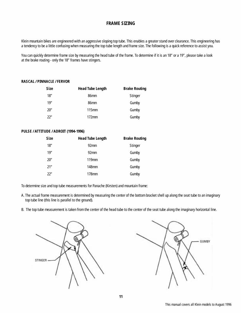
FRAME SIZING
Klein mountain bikes are engineered with an aggressive sloping top tube. This enables a greater stand over clearance. This engineering has a tendency to be a little confusing when measuring the top tube length and frame size. The following is a quick reference to assist you.
You can quickly determine frame size by measuring the head tube of the frame. To determine if it is an 18” or a 19”, please take a look at the brake routing - only the 18” frames have stingers.
RASCAL / PINNACLE / FERVOR
Size Head Tube Length Brake Routing
18” 86mm Stinger
19” 86mm Gumby
20” 115mm Gumby
22” 172mm Gumby
PULSE / ATTITUDE / ADROIT (1994-1996)
Size Head Tube Length Brake Routing
18” 92mm Stinger
19” 92mm Gumby
20” 119mm Gumby
21” 148mm Gumby
22” 178mm Gumby
To determine size and top tube measurements for Panache (Kirsten) and mountain frame:
A. The actual frame measurement is determined by measuring the center of the bottom bracket shell up along the seat tube to an imaginary top tube line (this line is parallel to the ground).
B. The top tube measurement is taken from the center of the head tube to the center of the seat tube along the imaginary horizontal line.
This manual covers all Klein models to August 1996
12
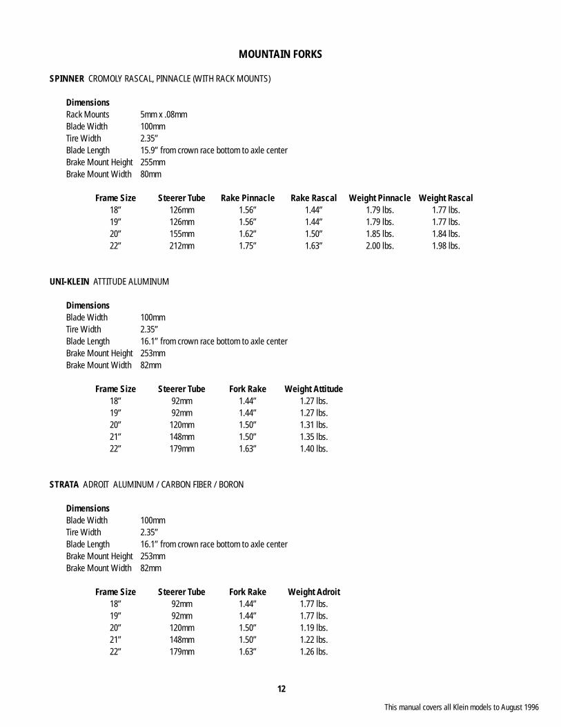
MOUNTAIN FORKS
SPINNER CROMOLY RASCAL, PINNACLE (WITH RACK MOUNTS)
Dimensions Rack Mounts 5mm x .08mm Blade Width 100mm Tire Width 2.35” Blade Length 15.9” from crown race bottom to axle center Brake Mount Height 255mm Brake Mount Width 80mm
Frame Size Steerer Tube Rake Pinnacle Rake Rascal Weight Pinnacle Weight Rascal 18” 126mm 1.56” 1.44” 1.79 lbs. 1.77 lbs. 19” 126mm 1.56” 1.44” 1.79 lbs. 1.77 lbs. 20” 155mm 1.62” 1.50” 1.85 lbs. 1.84 lbs. 22” 212mm 1.75” 1.63” 2.00 lbs. 1.98 lbs.
UNI-KLEIN ATTITUDE ALUMINUM
Dimensions Blade Width 100mm Tire Width 2.35” Blade Length 16.1” from crown race bottom to axle center Brake Mount Height 253mm Brake Mount Width 82mm
Frame Size Steerer Tube Fork Rake Weight Attitude 18” 92mm 1.44” 1.27 lbs. 19” 92mm 1.44” 1.27 lbs. 20” 120mm 1.50” 1.31 lbs. 21” 148mm 1.50” 1.35 lbs. 22” 179mm 1.63” 1.40 lbs.
STRATA ADROIT ALUMINUM / CARBON FIBER / BORON
Dimensions Blade Width 100mm Tire Width 2.35” Blade Length 16.1” from crown race bottom to axle center Brake Mount Height 253mm Brake Mount Width 82mm
Frame Size Steerer Tube Fork Rake Weight Adroit 18” 92mm 1.44” 1.77 lbs. 19” 92mm 1.44” 1.77 lbs. 20” 120mm 1.50” 1.19 lbs. 21” 148mm 1.50” 1.22 lbs. 22” 179mm 1.63” 1.26 lbs.
This manual covers all Klein models to August 1996
13
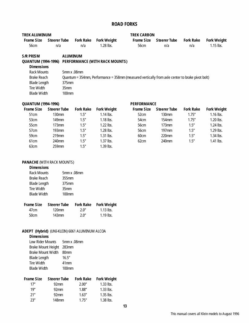
ROAD FORKS
TREK ALUMINUM TREK CARBON Frame Size Steerer Tube Fork Rake Fork Weight Frame Size Steerer Tube Fork Rake Fork Weight 56cm n/a n/a 1.28 lbs. 56cm n/a n/a 1.15 lbs.
S/R PRISM ALUMINUMQUANTUM (1994-1996) PERFORMANCE (WITH RACK MOUNTS) Dimensions Rack Mounts 5mm x .08mm Brake Reach Quantum = 354mm, Performance = 358mm (measured vertically from axle center to brake pivot bolt) Blade Length 375mm Tire Width 35mm Blade Width 100mm
QUANTUM (1994-1996) PERFORMANCE Frame Size Steerer Tube Fork Rake Fork Weight Frame Size Steerer Tube Fork Rake Fork Weight 51cm 130mm 1.5” 1.14 lbs. 52cm 130mm 1.75” 1.16 lbs. 53cm 149mm 1.5” 1.18 lbs. 54cm 154mm 1.75” 1.20 lbs. 55cm 173mm 1.5” 1.22 lbs. 56cm 173mm 1.5” 1.24 lbs. 57cm 193mm 1.5” 1.28 lbs. 56cm 197mm 1.5” 1.29 lbs. 59cm 219mm 1.5” 1.31 lbs. 60cm 220mm 1.5” 1.34 lbs. 61cm 240mm 1.5” 1.37 lbs. 62cm 240mm 1.5” 1.41 lbs. 63cm 259mm 1.5” 1.39 lbs.
PANACHE (WITH RACK MOUNTS) Dimensions Rack Mounts 5mm x .08mm Brake Reach 355mm Blade Length 375mm Tire Width 35mm Blade Width 100mm
Frame Size Steerer Tube Fork Rake Fork Weight 47cm 120mm 2.0” 1.13 lbs. 50cm 143mm 2.0” 1.19 lbs.
ADEPT (Hybrid) (UNI-KLEIN) 6061 ALUMINUM ALCOA Dimensions Low Rider Mounts 5mm x .08mm Brake Mount Height 283mm Brake Mount Width 80mm Blade Length 16.5” Tire Width 41mm Blade Width 100mm
Frame Size Steerer Tube Fork Rake Fork Weight 17” 92mm 2.00” 1.33 lbs. 19” 92mm 1.88” 1.33 lbs. 21” 92mm 1.63” 1.35 lbs. 23” 148mm 1.75” 1.38 lbs.
This manual covers all Klein models to August 1996
14
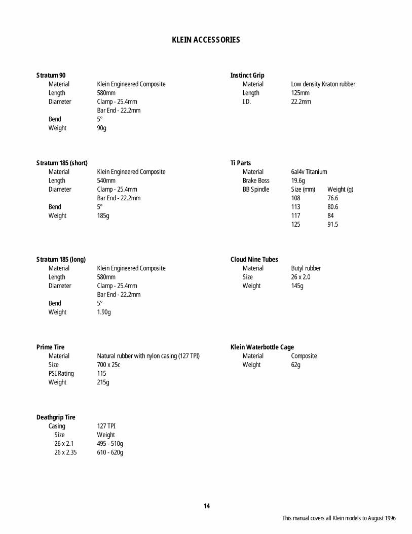
KLEIN ACCESSORIES
Stratum 90 Instinct Grip Material Klein Engineered Composite Material Low density Kraton rubber Length 580mm Length 125mm Diameter Clamp - 25.4mm I.D. 22.2mm Bar End - 22.2mm Bend 5° Weight 90g
Stratum 185 (short) Ti Parts Material Klein Engineered Composite Material 6al4v Titanium Length 540mm Brake Boss 19.6g Diameter Clamp - 25.4mm BB Spindle Size (mm) Weight (g) Bar End - 22.2mm 108 76.6 Bend 5° 113 80.6 Weight 185g 117 84 125 91.5
Stratum 185 (long) Cloud Nine Tubes Material Klein Engineered Composite Material Butyl rubber Length 580mm Size 26 x 2.0 Diameter Clamp - 25.4mm Weight 145g Bar End - 22.2mm Bend 5° Weight 1.90g
Prime Tire Klein Waterbottle Cage Material Natural rubber with nylon casing (127 TPI) Material Composite Size 700 x 25c Weight 62g PSI Rating 115 Weight 215g
Deathgrip Tire Casing 127 TPI Size Weight 26 x 2.1 495 - 510g 26 x 2.35 610 - 620g
This manual covers all Klein models to August 1996
15
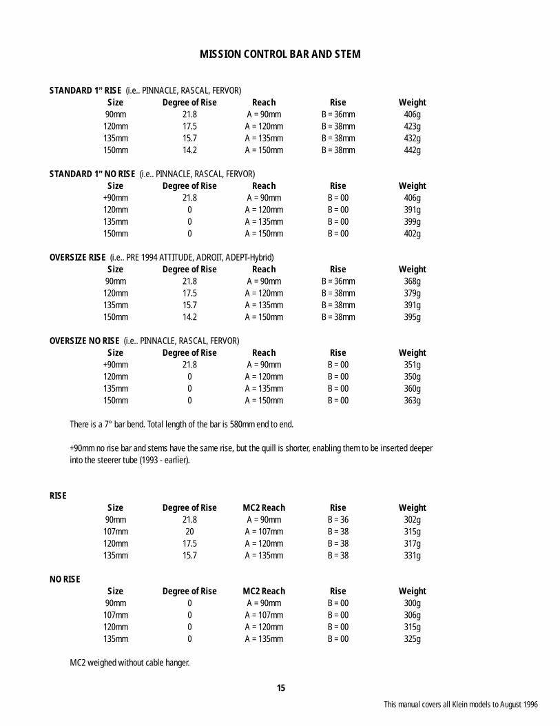
MISSION CONTROL BAR AND STEM
STANDARD 1” RISE (i.e.. PINNACLE, RASCAL, FERVOR) Size Degree of Rise Reach Rise Weight 90mm 21.8 A = 90mm B = 36mm 406g 120mm 17.5 A = 120mm B = 38mm 423g 135mm 15.7 A = 135mm B = 38mm 432g 150mm 14.2 A = 150mm B = 38mm 442g
STANDARD 1” NO RISE (i.e.. PINNACLE, RASCAL, FERVOR) Size Degree of Rise Reach Rise Weight +90mm 21.8 A = 90mm B = 00 406g 120mm 0 A = 120mm B = 00 391g 135mm 0 A = 135mm B = 00 399g 150mm 0 A = 150mm B = 00 402g
OVERSIZE RISE (i.e.. PRE 1994 ATTITUDE, ADROIT, ADEPT-Hybrid) Size Degree of Rise Reach Rise Weight 90mm 21.8 A = 90mm B = 36mm 368g 120mm 17.5 A = 120mm B = 38mm 379g 135mm 15.7 A = 135mm B = 38mm 391g 150mm 14.2 A = 150mm B = 38mm 395g
OVERSIZE NO RISE (i.e.. PINNACLE, RASCAL, FERVOR) Size Degree of Rise Reach Rise Weight +90mm 21.8 A = 90mm B = 00 351g 120mm 0 A = 120mm B = 00 350g 135mm 0 A = 135mm B = 00 360g 150mm 0 A = 150mm B = 00 363g
There is a 7° bar bend. Total length of the bar is 580mm end to end.
+90mm no rise bar and stems have the same rise, but the quill is shorter, enabling them to be inserted deeper into the steerer tube (1993 - earlier).
RISE Size Degree of Rise MC2 Reach Rise Weight 90mm 21.8 A = 90mm B = 36 302g 107mm 20 A = 107mm B = 38 315g 120mm 17.5 A = 120mm B = 38 317g 135mm 15.7 A = 135mm B = 38 331g
NO RISE Size Degree of Rise MC2 Reach Rise Weight 90mm 0 A = 90mm B = 00 300g 107mm 0 A = 107mm B = 00 306g 120mm 0 A = 120mm B = 00 315g 135mm 0 A = 135mm B = 00 325g
MC2 weighed without cable hanger.
This manual covers all Klein models to August 1996
16
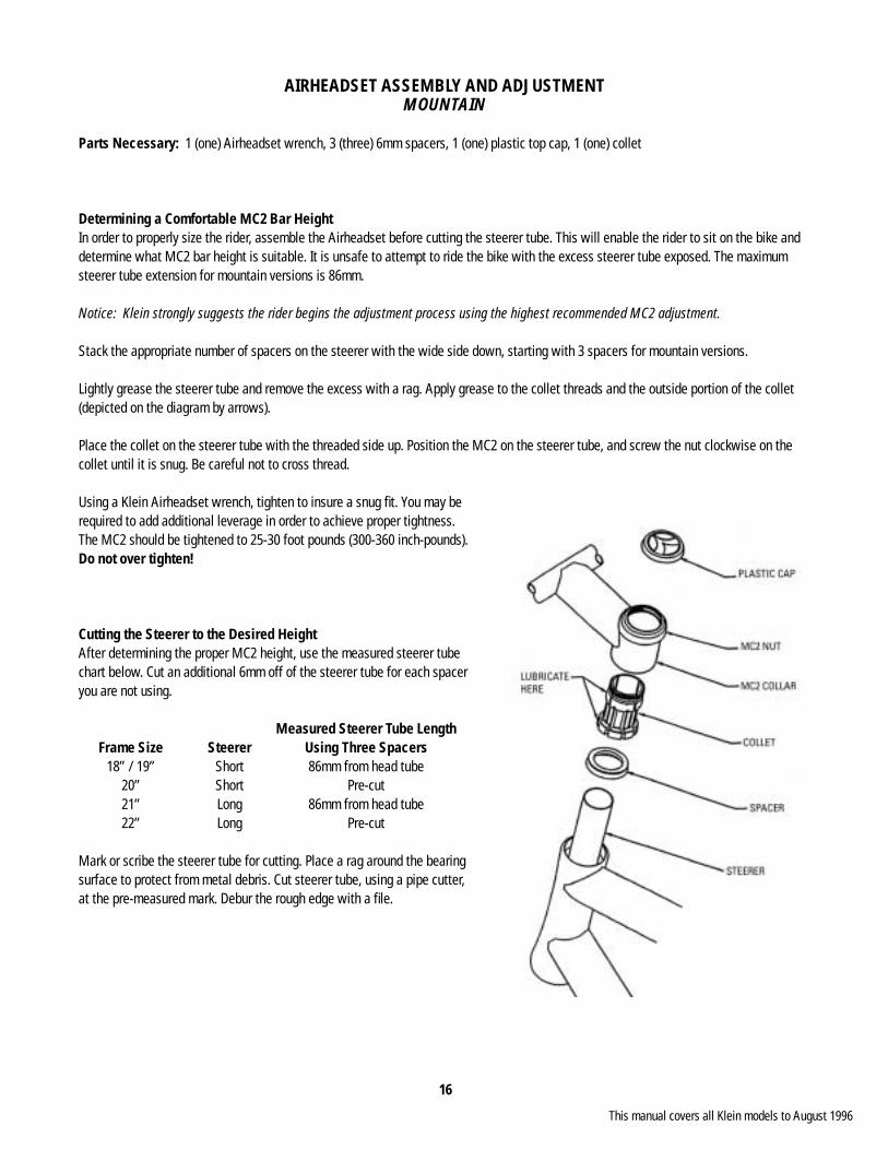
AIRHEADSET ASSEMBLY AND ADJUSTMENTMOUNTAIN
Parts Necessary: 1 (one) Airheadset wrench, 3 (three) 6mm spacers, 1 (one) plastic top cap, 1 (one) collet
Determining a Comfortable MC2 Bar HeightIn order to properly size the rider, assemble the Airheadset before cutting the steerer tube. This will enable the rider to sit on the bike and determine what MC2 bar height is suitable. It is unsafe to attempt to ride the bike with the excess steerer tube exposed. The maximum steerer tube extension for mountain versions is 86mm.
Notice: Klein strongly suggests the rider begins the adjustment process using the highest recommended MC2 adjustment.
Stack the appropriate number of spacers on the steerer with the wide side down, starting with 3 spacers for mountain versions.
Lightly grease the steerer tube and remove the excess with a rag. Apply grease to the collet threads and the outside portion of the collet (depicted on the diagram by arrows).
Place the collet on the steerer tube with the threaded side up. Position the MC2 on the steerer tube, and screw the nut clockwise on the collet until it is snug. Be careful not to cross thread.
Using a Klein Airheadset wrench, tighten to insure a snug fi t. You may be required to add additional leverage in order to achieve proper tightness. The MC2 should be tightened to 25-30 foot pounds (300-360 inch-pounds). Do not over tighten!
Cutting the Steerer to the Desired HeightAfter determining the proper MC2 height, use the measured steerer tube chart below. Cut an additional 6mm off of the steerer tube for each spacer you are not using.
Measured Steerer Tube Length Frame Size Steerer Using Three Spacers 18” / 19” Short 86mm from head tube 20” Short Pre-cut 21” Long 86mm from head tube 22” Long Pre-cut
Mark or scribe the steerer tube for cutting. Place a rag around the bearing surface to protect from metal debris. Cut steerer tube, using a pipe cutter, at the pre-measured mark. Debur the rough edge with a fi le.
This manual covers all Klein models to August 1996
17
AIRHEADSET ASSEMBLY AND ADJUSTMENTROAD
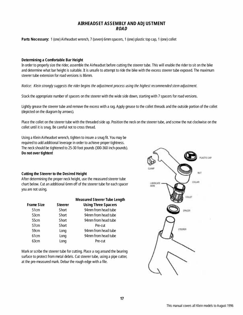
Parts Necessary: 1 (one) Airheadset wrench, 7 (seven) 6mm spacers, 1 (one) plastic top cap, 1 (one) collet
Determining a Comfortable Bar HeightIn order to properly size the rider, assemble the Airheadset before cutting the steerer tube. This will enable the rider to sit on the bike and determine what bar height is suitable. It is unsafe to attempt to ride the bike with the excess steerer tube exposed. The maximum steerer tube extension for road versions is 86mm.
Notice: Klein strongly suggests the rider begins the adjustment process using the highest recommended stem adjustment.
Stack the appropriate number of spacers on the steerer with the wide side down, starting with 7 spacers for road versions.
Lightly grease the steerer tube and remove the excess with a rag. Apply grease to the collet threads and the outside portion of the collet (depicted on the diagram by arrows).
Place the collet on the steerer tube with the threaded side up. Position the neck on the steerer tube, and screw the nut clockwise on the collet until it is snug. Be careful not to cross thread.
Using a Klein Airheadset wrench, tighten to insure a snug fi t. You may be required to add additional leverage in order to achieve proper tightness. The neck should be tightened to 25-30 foot pounds (300-360 inch-pounds). Do not over tighten!
Cutting the Steerer to the Desired HeightAfter determining the proper neck height, use the measured steerer tube chart below. Cut an additional 6mm off of the steerer tube for each spacer you are not using.
Measured Steerer Tube Length Frame Size Steerer Using Three Spacers 51cm Short 94mm from head tube 53cm Short 94mm from head tube 55cm Short 94mm from head tube 57cm Short Pre-cut 59cm Long 94mm from head tube 61cm Long 94mm from head tube 63cm Long Pre-cut
Mark or scribe the steerer tube for cutting. Place a rag around the bearing surface to protect from metal debris. Cut steerer tube, using a pipe cutter, at the pre-measured mark. Debur the rough edge with a fi le.
This manual covers all Klein models to August 1996
18
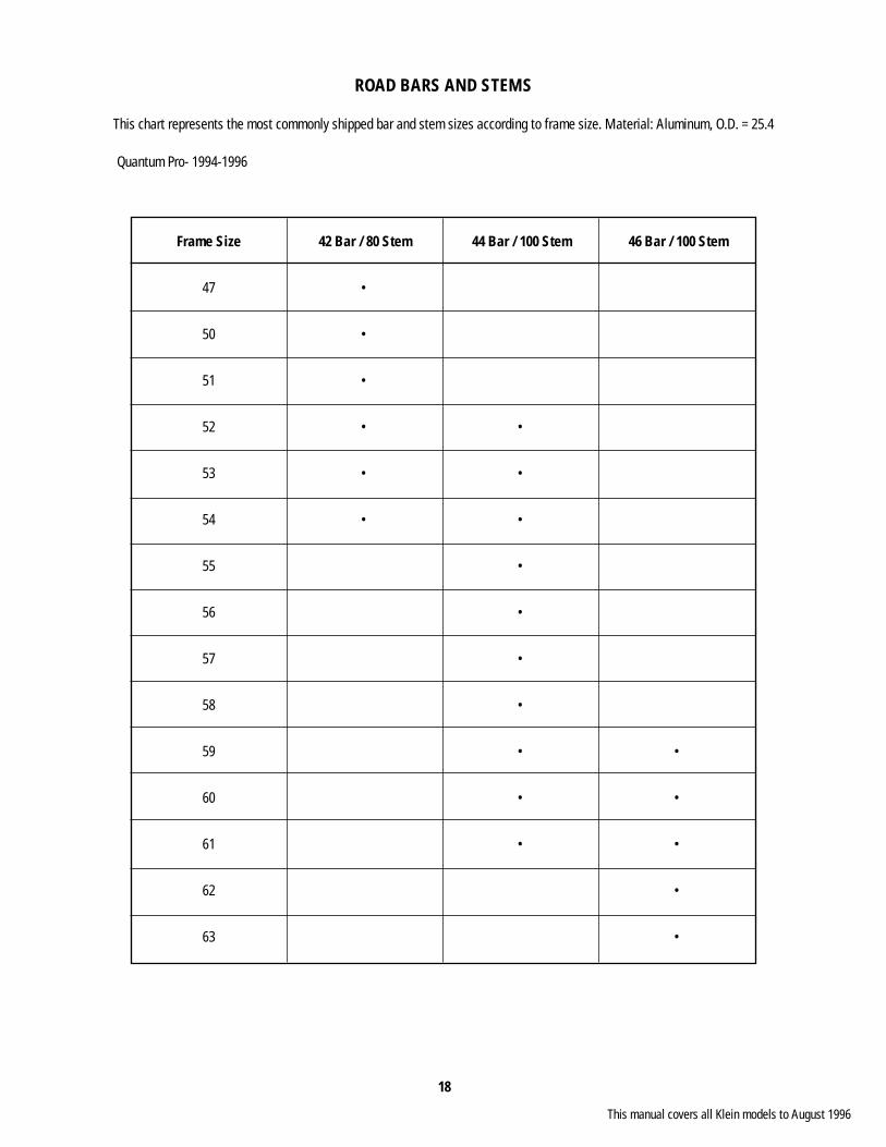
ROAD BARS AND STEMS
This chart represents the most commonly shipped bar and stem sizes according to frame size. Material: Aluminum, O.D. = 25.4
Quantum Pro- 1994-1996
Frame Size 42 Bar / 80 Stem 44 Bar / 100 Stem 46 Bar / 100 Stem
47 •
50 •
51 •
52 • •
53 • •
54 • •
55 •
56 •
57 •
58 •
59 • •
60 • •
61 • •
62 •
63 •
This manual covers all Klein models to August 1996
19
ZIP GRIP SEATPOST ADJUSTMENT
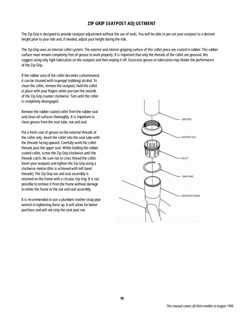
The Zip Grip is designed to provide seatpost adjustment without the use of tools. You will be able to pre-set your seatpost to a desired height prior to your ride and, if needed, adjust your height during the ride.
The Zip Grip uses an internal collet system. The exterior and interior gripping surface of this collet piece are coated in rubber. This rubber surface must remain completely free of grease to work properly. It is important that only the threads of the collet are greased. We suggest using only light lubrication on the seatpost and then wiping it off. Excessive grease or lubrication may hinder the performance of the Zip Grip.
If the rubber area of the collet becomes contaminated, it can be cleaned with isopropyl (rubbing) alcohol. To clean the collet, remove the seatpost; hold the collet in place with your fi ngers while you turn the outside of the Zip Grip counter clockwise. Turn until the collet is completely disengaged.
Remove the rubber coated collet from the rubber seal and clean all surfaces thoroughly. It is important to clean grease from the seat tube, nut and seal.
Put a fresh coat of grease on the external threads of the collet only. Insert the collet into the seat tube with the threads facing upward. Carefully work the collet threads past the upper seal. While holding the rubber coated collet, screw the Zip Grip clockwise until the threads catch. Be sure not to cross thread the collet. Insert your seatpost and tighten the Zip Grip using a clockwise motion (this is achieved with left hand threads). The Zip Grip nut and seal assembly is retained on the frame with a circular clip ring. It is not possible to remove it from the frame without damage to either the frame or the nut and seal assembly.
It is recommended to use a plumbers leather strap pipewrench in tightening these up. It will allow for betterpurchase and will not strip the seat post nut.
This manual covers all Klein models to August 1996
20
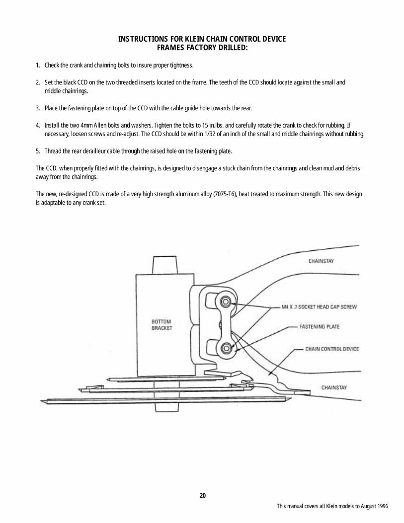
INSTRUCTIONS FOR KLEIN CHAIN CONTROL DEVICEFRAMES FACTORY DRILLED:
1. Check the crank and chainring bolts to insure proper tightness.
2. Set the black CCD on the two threaded inserts located on the frame. The teeth of the CCD should locate against the small and middle chainrings.
3. Place the fastening plate on top of the CCD with the cable guide hole towards the rear.
4. Install the two 4mm Allen bolts and washers. Tighten the bolts to 15 in.lbs. and carefully rotate the crank to check for rubbing. If necessary, loosen screws and re-adjust. The CCD should be within 1/32 of an inch of the small and middle chainrings without rubbing.
5. Thread the rear derailleur cable through the raised hole on the fastening plate.
The CCD, when properly fi tted with the chainrings, is designed to disengage a stuck chain from the chainrings and clean mud and debris away from the chainrings.
The new, re-designed CCD is made of a very high strength aluminum alloy (7075-T6), heat treated to maximum strength. This new design is adaptable to any crank set.
This manual covers all Klein models to August 1996
21
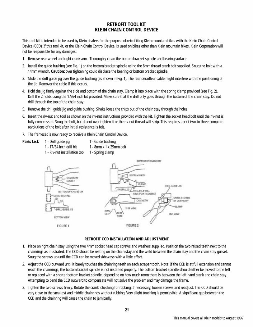
RETROFIT TOOL KITKLEIN CHAIN CONTROL DEVICE
This tool kit is intended to be used by Klein dealers for the purpose of retrofi tting Klein mountain bikes with the Klein Chain Control Device (CCD). If this tool kit, or the Klein Chain Control Device, is used on bikes other than Klein mountain bikes, Klein Corporation will not be responsible for any damages.
1. Remove rear wheel and right crank arm. Thoroughly clean the bottom bracket spindle and bearing surface.
2. Install the guide bushing (see Fig. 1) on the bottom bracket spindle using the 8mm thread crank bolt supplied. Snug the bolt with a 14mm wrench. Caution: over tightening could displace the bearing or bottom bracket spindle.
3. Slide the drill guide jig over the guide bushing (as shown in Fig. 1). The rear derailleur cable might interfere with the positioning of the jig. Remover the cable if this occurs.
4. Hold the jig fi rmly against the side and bottom of the chain stay. Clamp it into place with the spring clamp provided (see Fig. 2). Drill the 2 holds using the 17/64 inch bit provided. Make sure that the drill only goes through the bottom of the chain stay. Do not drill through the top of the chain stay.
5. Remove the drill guide jig and guide bushing. Shake loose the chips out of the chain stay through the holes.
6. Insert the riv-nut and tool as shown on the riv-nut instructions provided with the kit. Tighten the socket head bolt until the riv-nut is fully compressed. Snug the bolt, but do not over tighten it or the riv-nut thread will strip. This requires about two to three complete revolutions of the bolt after initial resistance is felt.
7. The frameset is now ready to receive a Klein Chain Control Device.
Parts List: 1 - Drill guide jig 1 - Guide bushing 1 - 17/64 inch drill bit 1 - 8mm x 1 x 25mm bolt 1 - Riv-nut installation tool 1 - Spring clamp
RETROFIT CCD INSTALLATION AND ADJUSTMENT
1. Place on right chain stay using the two 4mm socket head cap screws and washers supplied. Position the two raised teeth next to the chainrings as illustrated. The CCD should be resting on the chain stay and the weld between the chain stay and the chain stay gusset. Snug the screws up until the CCD can be moved sideways with a little effort.
2. Adjust the CCD outward until it barely touches the chainring teeth on each scraper tooth. Note: If the CCD is at full extension and cannot reach the chainrings, the bottom bracket spindle is not installed properly. The bottom bracket spindle should either be moved to the left or replaced with a shorter bottom bracket spindle, depending on how much room there is between the left hand crank and chain stay. Attempting to bend the CCD outward to compensate will not solve the problem and may damage the frame.
3. Tighten the two screws fi rmly. Rotate the crank, checking for rubbing. If necessary, loosen screws and readjust. The CCD should be very close to the smallest and middle chainrings without rubbing. Very slight touching is permissible. A signifi cant gap between the CCD and the chainring will cause the chain to jam badly.
This manual covers all Klein models to August 1996
22
BOTTOM BRACKET SPECIFICATIONS
BOTTOM BRACKET SPINDLE
Material 4340 Steel; hardened to 42 - 47 RC
Taper Length 19.8mm
Taper Square 12.6mm
Thread Size 8 x 1mm, 25mm deep
Outside Diameter 17mm
Lengths Available (mm) 104, 106, 108, 113, 117, 119, 121, 125, 130, 135
BOTTOM BRACKET BEARING
F.A.G. Sealed Bearing
Inside Diameter 17mm
Outside Diameter 34.9mm
Width 10mm
BOTTOM BRACKET SHELL
All Mountain Pre 1994 Material Aluminum
Fervor 1994-1995 Shell Length 76.21mm
Quantum, Performance 1994-1996 Shell Outer Diameter 41.28mm
Panache, Pinnacle, Adept All years Shell Inner Diameter 35.0mm
Q II, Aeolus All years
Adroit, Attitude Pulse 1994-1996 Material Aluminum
Quantum Pro 1994-1996 Shell Length 72mm
Shell Outer Diameter 41.28mm
Shell Inside Diameter 35.0mm
This manual covers all Klein models to August 1996

23
BOTTOM BRACKET SETTINGS - MOUNTAIN
Adroit Adroit Attitude Attitude Pulse Rascal Fervor Pinnacle Adept-Hybrid Brand Model Year 1991-1993 1994 1990-1993 1994 1994 1990-1993 1993-1994 1989-1994 All Shimano XTR - 1996 108 x 18 108 x 18 108 x 18 108 x 18 108 x 18 108 x 18 108 x 18 108 x 18 108 x 18 XT, DX 1993 125 x 26 125 x 26 125 x 26 125 x 26 125 x 26 125 x 26 125 x 26 125 x 26 121 x 23 XT, LX 1994-95 108 x 18 106 x 16 108 x 18 106 x 16 106 x 16 108 x 18 108 x 18 108 x 18 108 x 18 LX Pre 1993 125 x 26 125 x 26 125 x 26 125 x 26 125 x 26 125 x 26 125 x 26 125 x 26 121 x 23 DLX 113 x 20 113 x 20 113 x 20 113 x 20 113 x 20 113 x 20 113 x 20 113 x 20 113 x 20 STX 1993-95 113 x 21 108 x 18 113 x 21 108 x 18 108 x 18 113 x 21 113 x 21 113 x 21 700 CX 121 x 17 Suntour XC Pro, Comp 125 x 26 125 x 26 125 x 26 125 x 26 125 x 26 121 x 22 XC Pro Micro 113 x 20 113 x 20 113 x 20 113 x 20 113 x 20 XC Comp Micro 117 x 24 117 x 24 117 x 24 117 x 24 117 x 24 113 x 20 XC Expert 113 x 21 113 x 21 113 x 21 113 x 21 113 x 21 XC Ltd 125 x 26 125 x 26 125 x 26 125 x 26 125 x 26 Campy Record Off Road 113 x 21 113 x 21 113 x 21 113 x 21 113 x 21 Euclid 135 x 32 135 x 32 135 x 32 135 x 32 135 x 32 125 x 23 Centaur 121 x 27 121 x 27 121 x 27 121 x 27 121 x 27 119 x 24 Misc. Ritchey 125 x 26 125 x 26 125 x 26 125 x 26 125 x 26 Grafton Joy Stix 121 x 23 121 x 23 121 x 23 121 x 23 121 x 23 117 x 21 Specialized ST-4 125 x 26 125 x 26 125 x 26 125 x 26 125 x 26 Mavic 132 x 31 132 x 31 132 x 31 132 x 31 132 x 31 Cooks 1992 130 x 29 130 x 29 130 x 29 130 x 29 130 x 29 Cooks CBR 125 x 24 125 x 24 125 x 24 125 x 24 125 x 24 Cooks RSR 117 x 22 117 x 22 117 x 22 117 x 22 117 x 22 Cooks E 113 x 21 113 x 21 113 x 21 Top Line 125 x 25 125 x 25 125 x 25 125 x 25 125 x 25 Kooka 125 x 26 125 x 26 125 x 26 Race Face 125 x 25 125 x 25 125 x 25 Race Face L.P. 108 x 18 108 x 18 108 x 18 Sampson 130 x 30 130 x 30 130 x 30 Sampson Stratics Hershey 113 x 23 113 x 23 113 x 23 AC 121 x 24 121 x 24 121 x 24
Bold settings require the drive side bearing to be inset 3mm from the shell edge.Italicized settings require the non-drive side bearing to be inset 3mm from the shell edge.
This manual covers all Klein m
odels to August 1996

24
BOTTOM BRACKET SETTINGS - ROAD
Quantum Performance Panache Quantum II Quantum Pro Aeolus Brand Model Year 1994-1996 1993-1996 1994-1996 1993-1996
Shimano Dura-Ace 1993-95 108 x 18 108 x 18 108 x 18 113 x 20
Dura-Ace Pre 1993 119 x 22 119 x 22 119 x 22 117 x 22
Ultegra 117 x 23 117 x 23 117 x 23 108 x 14 108 x 16 117 x 22
105 1993-95 108 x 18 108 x 18 108 x 18 108 x 18
105 Pre 1993 117 x 23 117 x 23 117 x 23
RX 100 113 x 20 113 x 20 113 x 20 117 x 22
RX Touring 121 x 23 121 x 23 121 x 23
XT / DX 119 x 22 119 x 22 119 x 22
LX 117 x 24 117 x 24 117 x 24
RSX 117 x 24 117 x 24 117 x 24
Suntour Superbe Pro 113 x 21 113 x 21 113 x 21
Campy Record 1995 108 x 18 108 x 18 18 x 18 108 x 18 108 x 20
Chorus 1995 108 x 18 108 x 18 18 x 18 108 x 18 108 x 20
Athena 1995 108 x 18 108 x 18 18 x 18 108 x 18 108 x 20
Veloce 1995 108 x 18 108 x 18 18 x 18 108 x 18 108 x 20
Super Record 121 x 24 121 x 24 121 x 24
Nuovo Record 121 x 24 121 x 24 121 x 24
Record Pre 1995 113 x 20 113 x 20 113 x 20 108 x 18 108 x 20 117 x 22
Chorus Pre 1995 113 x 20 113 x 20 113 x 20 108 x 20 108 x 20
Athena Pre 1995 117 x 25 117 x 25 117 x 25 113 x 23 108 x 20 117 x 22
Veloce Pre 1995 108 x 18 108 x 18 108 x 18 108 x 18 108 x 20 113 x 21
Misc. AC 113 x 20 113 x 20 113 x 20
Mavic Double 117 x 23 117 x 23 117 x 23
Sachs Double 117 x 24 117 x 24 117 x 24
Grafton 119 x 21
Top Line
Bold settings require the drive side bearing to be inset 3mm from the shell edge.Italicized settings require the non-drive side bearing to be inset 3mm from the shell edge.
This manual covers all Klein m
odels to August 1996
25
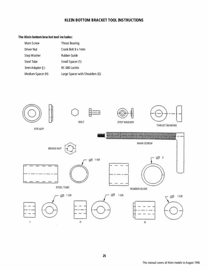
KLEIN BOTTOM BRACKET TOOL INSTRUCTIONS
The Klein bottom bracket tool includes:
Main Screw Thrust Bearing
Driver Nut Crank Bolt 8 x 1mm
Step Washer Rubber Guide
Steel Tube Small Spacer (1)
3mm Adapter (J) RC 680 Loctite
Medium Spacer (H) Large Spacer with Shoulders (G)
This manual covers all Klein models to August 1996

26
PART A: REMOVAL OF SPINDLE AND BEARINGS
A) 1. Remove the crank arms. Record the current bottom bracket setting by measuring the total spindle length and the non-drive side setting (measured from the bottom bracket shell to the end of the Spindle).
A) 2. On the non-drive side, place spacer (1) over the spindle followed by the step washer and crank bolt (tighten crank bolt fi nger tight).
A) 3. On the drive side, place the rubber guide over the bottom bracket shell. Now, slide the steel tube into the rubber guide until it is up against the bottom bracket shell. While setting up the main screw (important), maintain a well lubricated main screw during the entire procedure (a light penetrating oil is preferred). Thread on the driver nut all the way followed by the thrust bearing. Then place spacer (G) with the shoulders away from the thrust bearing, over the main screw. Now, place the entire assembly into the steel tube and thread the main screw into the spindle (see Fig. 1). Hold the main screw in place and thread the driver nut towards the bottom bracket. This continued action will extract the entire unit.
This manual covers all Klein models to August 1996
27
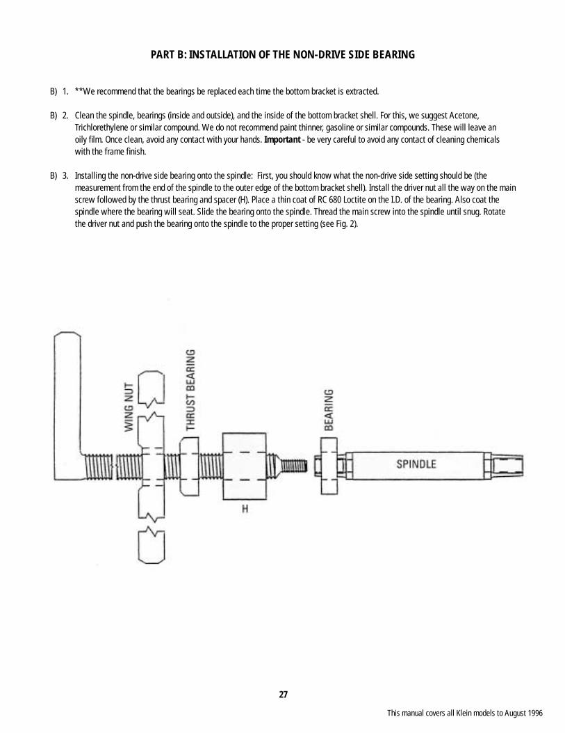
PART B: INSTALLATION OF THE NON-DRIVE SIDE BEARING
B) 1. **We recommend that the bearings be replaced each time the bottom bracket is extracted.
B) 2. Clean the spindle, bearings (inside and outside), and the inside of the bottom bracket shell. For this, we suggest Acetone, Trichlorethylene or similar compound. We do not recommend paint thinner, gasoline or similar compounds. These will leave an oily fi lm. Once clean, avoid any contact with your hands. Important - be very careful to avoid any contact of cleaning chemicals with the frame fi nish.
B) 3. Installing the non-drive side bearing onto the spindle: First, you should know what the non-drive side setting should be (the measurement from the end of the spindle to the outer edge of the bottom bracket shell). Install the driver nut all the way on the main screw followed by the thrust bearing and spacer (H). Place a thin coat of RC 680 Loctite on the I.D. of the bearing. Also coat the spindle where the bearing will seat. Slide the bearing onto the spindle. Thread the main screw into the spindle until snug. Rotate the driver nut and push the bearing onto the spindle to the proper setting (see Fig. 2).
This manual covers all Klein models to August 1996
28
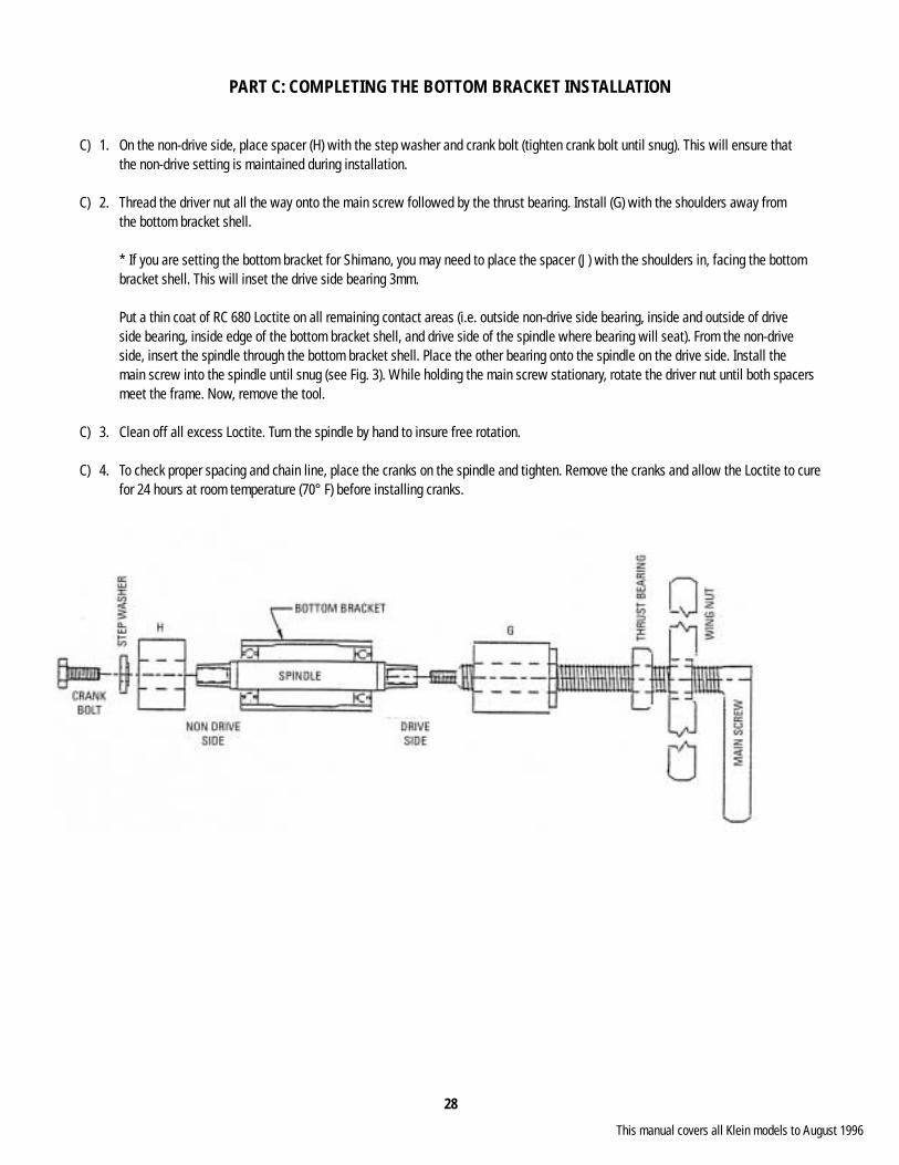
PART C: COMPLETING THE BOTTOM BRACKET INSTALLATION
C) 1. On the non-drive side, place spacer (H) with the step washer and crank bolt (tighten crank bolt until snug). This will ensure that the non-drive setting is maintained during installation.
C) 2. Thread the driver nut all the way onto the main screw followed by the thrust bearing. Install (G) with the shoulders away from the bottom bracket shell.
* If you are setting the bottom bracket for Shimano, you may need to place the spacer (J) with the shoulders in, facing the bottom bracket shell. This will inset the drive side bearing 3mm.
Put a thin coat of RC 680 Loctite on all remaining contact areas (i.e. outside non-drive side bearing, inside and outside of drive side bearing, inside edge of the bottom bracket shell, and drive side of the spindle where bearing will seat). From the non-drive side, insert the spindle through the bottom bracket shell. Place the other bearing onto the spindle on the drive side. Install the main screw into the spindle until snug (see Fig. 3). While holding the main screw stationary, rotate the driver nut until both spacers meet the frame. Now, remove the tool.
C) 3. Clean off all excess Loctite. Turn the spindle by hand to insure free rotation.
C) 4. To check proper spacing and chain line, place the cranks on the spindle and tighten. Remove the cranks and allow the Loctite to cure for 24 hours at room temperature (70° F) before installing cranks.
This manual covers all Klein models to August 1996

29
REMOVAL AND INSTALLATION OF THE KLEIN ATTITUDE HEADSET BEARINGS(Original tool design only)
The Klein headset installation tools include the following parts (see Fig. 1 on page 31):
Cage AssemblyThe cage assembly consists of a lower ring, in which either end of the head tube seats, connected to the top brace by side rails.
Threaded RodThis is a 26 inch piece of 5/8-11 threaded rod. It has holes drilled in one end so that a nut can be locked into place by a 3/16 inch hitch pin. The other end has a fi xed nut for applying torque.
Fork PusherThis is a 1/2 inch thick disk with a step in it. It seals on top of the fork and is used to push the fork from the bicycle.
Bearing PullerThis is a 1/4 inch thick u-shaped piece of steel. It sits in the bottom of the cage assembly and is used to remove a bearing from the fork.
Bearing RemoverThis part consists of two halves of a hat-shaped piece of steel. It is used to remove bearings from the headset.
Bearing PusherThis is a 2 inch hollow cylindrical piece of steel which is used to press the bearings into the head tube and pull the fork into place.
Fork ConeThis is a cone-shaped piece of steel about 1.5 inches long. It seals inside the bottom of the steerer and is used to pull the fork into the frame.
Two 5/8-11 NutsOne nut has a 3/16 hole so that it can be locked into place with a hitch pin to secure the tool being used on the threaded rod.
This manual covers all Klein models to August 1996
30
PART A: REMOVAL OF FORK AND BEARINGS
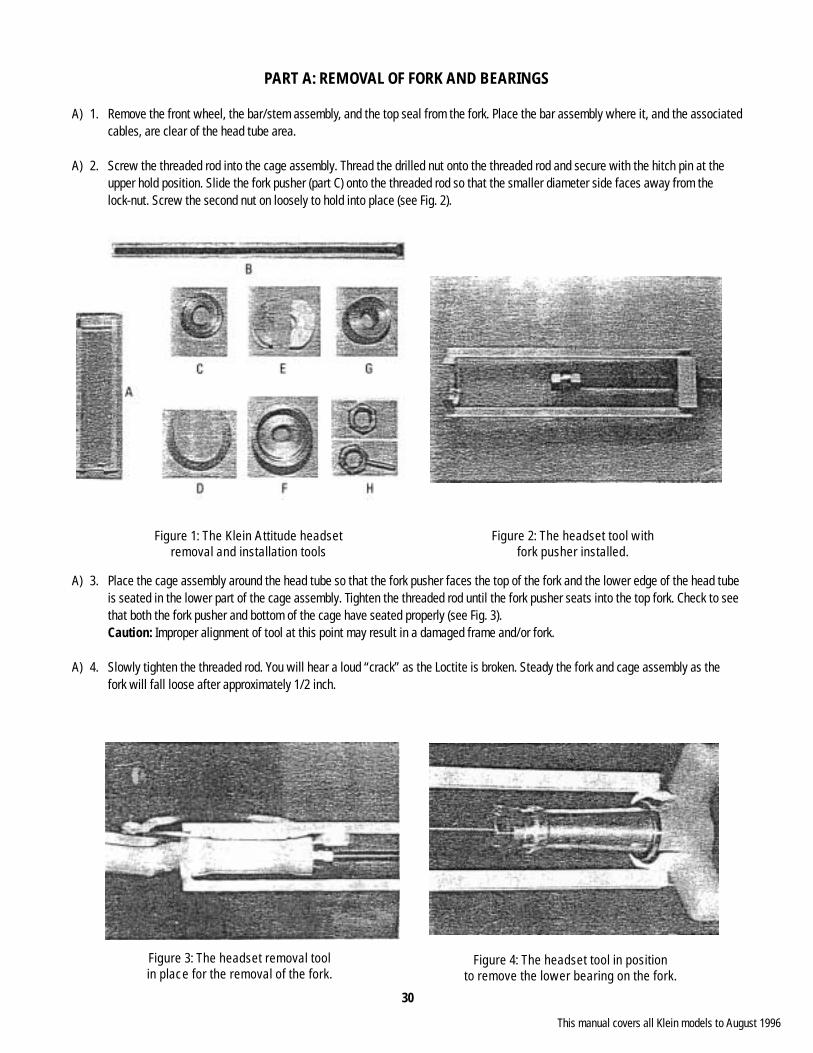
A) 1. Remove the front wheel, the bar/stem assembly, and the top seal from the fork. Place the bar assembly where it, and the associated cables, are clear of the head tube area.
A) 2. Screw the threaded rod into the cage assembly. Thread the drilled nut onto the threaded rod and secure with the hitch pin at the upper hold position. Slide the fork pusher (part C) onto the threaded rod so that the smaller diameter side faces away from the lock-nut. Screw the second nut on loosely to hold into place (see Fig. 2).
A) 3. Place the cage assembly around the head tube so that the fork pusher faces the top of the fork and the lower edge of the head tube is seated in the lower part of the cage assembly. Tighten the threaded rod until the fork pusher seats into the top fork. Check to see that both the fork pusher and bottom of the cage have seated properly (see Fig. 3).
Caution: Improper alignment of tool at this point may result in a damaged frame and/or fork.
A) 4. Slowly tighten the threaded rod. You will hear a loud “crack” as the Loctite is broken. Steady the fork and cage assembly as the fork will fall loose after approximately 1/2 inch.
FIGURE 4IMAGE & CAPTION
Figure 1: The Klein Attitude headsetremoval and installation tools
Figure 2: The headset tool withfork pusher installed.
Figure 4: The headset tool in positionto remove the lower bearing on the fork.
Figure 3: The headset removal toolin place for the removal of the fork.
This manual covers all Klein models to August 1996
31
PART A: REMOVAL OF FORK AND BEARINGS (cont.)
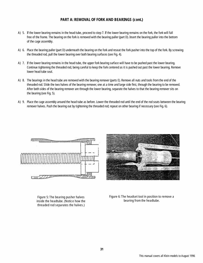
A) 5. If the lower bearing remains in the head tube, proceed to step 7. If the lower bearing remains on the fork, the fork will fall free of the frame. The bearing on the fork is removed with the bearing puller (part D). Insert the bearing puller into the bottom of the cage assembly.
A) 6. Place the bearing puller (part D) underneath the bearing on the fork and reseat the fork pusher into the top of the fork. By screwing the threaded rod, pull the lower bearing over both bearing surfaces (see Fig. 4).
A) 7. If the lower bearing remains in the head tube, the upper fork bearing surface will have to be pushed past the lower bearing. Continue tightening the threaded rod, being careful to keep the fork centered as it is pushed out past the lower bearing. Remove lower head tube seal.
A) 8. The bearings in the head tube are removed with the bearing remover (parts E). Remove all nuts and tools from the end of the threaded rod. Slide the two halves of the bearing remover, one at a time and large side fi rst, through the bearing to be removed. After both sides of the bearing remover are through the lower bearing, separate the halves to that the bearing remover sits on the bearing (see Fig. 5).
A) 9. Place the cage assembly around the head tube as before. Lower the threaded rod until the end of the rod seats between the bearing remover halves. Push the bearing out by tightening the threaded rod; repeat on other bearing if necessary (see Fig. 6).
Figure 5: The bearing pusher halvesinside the headtube. (Notice how thethreaded rod separates the halves.)
Figure 6: The headset tool in position to remove a bearing from the headtube.
This manual covers all Klein models to August 1996

32
PART B: INSTALLATION OF BEARINGS
B) 1. Carefully clean the parts of the head tube, fork and bearings that will be in contact with each other using the included brush and razor blade knife. All of the mounting surfaces must be completely clean of old Loctite, burrs or any other foreign matter. Rinse all mounting surfaces with Acetone or similar solvent. Do not allow the solvent to penetrate the bearing seals or come in contact with the bicycle’s paint. All of the mounting surfaces must be completely clean and free of oil.
B) 2. With the threaded rod still in the cage, thread the drilled nut to the higher hold position and secure the hitch pin. Thread the bearing pusher (part F) onto the rod and snug it against the lock nut (see Fig. 7).
B) 3. Apply a very thin layer of Loctite type RC 680 completely around the outside of the bearing and place it surely on top of the head tube. One side of the bearing has two grooves (one on the inside and one on the outside) in the races. This side should be placed toward the inside of the head tube to help prevent bearing contamination.
Note: The bearing may exhibit a slight slip fi t to a slight press fi t due to the slight variance in bearing size. In the case of the slip fi t, the bearings may slide into the head tube easily, and tools may not be necessary for this step. The bearing will be retained by the Loctite.
B) 4. Place the cage assembly around the head tube as before and begin to press the bearing into place. Be careful to keep the bearing straight as it is inserted (see Fig. 8). The bearing should insert with a minimal amount of force. If the bearing begins to bind, it has become tilted. Loosen the threaded rod, rotate the bearing pusher 180°, and retighten slightly. In most cases, the bearing will now seat properly. If the bearing remains tilted, remove the bearing as in steps A 8 and A 9, and repeat step B 3. Do not force the bearing.
Figure 7: The headset tool set up to push a bear-ing into the headtube.
Figure 8: The headset tool installing a bearing into the headtube.
This manual covers all Klein models to August 1996
33
PART B: INSTALLATION OF BEARINGS (cont.)
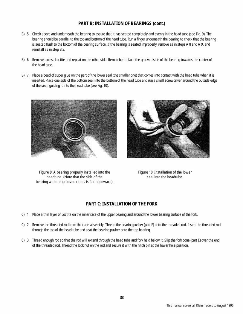
B) 5. Check above and underneath the bearing to assure that it has seated completely and evenly in the head tube (see Fig. 9). The bearing should be parallel to the top and bottom of the head tube. Run a fi nger underneath the bearing to check that the bearing is seated fl ush to the bottom of the bearing surface. If the bearing is seated improperly, remove as in steps A 8 and A 9, and reinstall as in step B 3.
B) 6. Remove excess Loctite and repeat on the other side. Remember to face the grooved side of the bearing towards the center of the head tube.
B) 7. Place a bead of super glue on the part of the lower seal (the smaller one) that comes into contact with the head tube when it is inserted. Place one side of the bottom seal into the bottom of the head tube and run a small screwdriver around the outside edge of the seal, guiding it into the head tube (see Fig. 10).
PART C: INSTALLATION OF THE FORK
C) 1. Place a thin layer of Loctite on the inner race of the upper bearing and around the lower bearing surface of the fork.
C) 2. Remove the threaded rod from the cage assembly. Thread the bearing pusher (part F) onto the threaded rod. Insert the threaded rod through the top of the head tube and seat the bearing pusher onto the top bearing.
C) 3. Thread enough rod so that the rod will extend through the head tube and fork held below it. Slip the fork cone (part E) over the end of the threaded rod. Thread the lock nut on the rod and secure it with the hitch pin at the lower hole position.
Figure 9: A bearing properly installed into the headtube. (Note that the side of the
bearing with the grooved races is facing inward).
Figure 10: Installation of the lowerseal into the headtube.
This manual covers all Klein models to August 1996

34
TOUCH-UP PAINT INSTRUCTIONSDurethane enamel is a polyurethane paint. Polyurethane paint must be mixed with a catalyst before application. The proper mixture is one part paint, one part catalyst. Once mixed, the paint will not remain stable and can’t be used again. In order to achieve the desired color, a two or three coat process is necessary. Each coat should be allowed to dry before applying additional coats.
Small touch-ups may not require the base coat. All coats, including the base coat, must be mixed equally with the catalyst. Each coat of paint should be applied singularly and allowed to dry before the next coat is applied. Touch-up areas will not obtain a glossy fi nish due to the lack of a clear coat.
The following is a list of past production colors. You must follow the directions in order to obtain a reasonable color match.
DESIRED COLOR BASE COAT SECOND COAT THIRD COAT Pearl Black Gloss Black Pearl Red None Bright Green White Bright Green None Pearl White White Pearl None Magenta White Magenta None Ultra Violet Silver Ultra Violet None Flare Yellow Magenta (light) None Gloss Black None Gloss Black None Candy Blue Candy Blue Base Candy Blue Top None Candy Teal Candy Teal Base Candy Teal Top None Candy Red Candy Red Base Candy Red Top None Bright Silver Bright Silver None None Ice Teal Candy Green Base Nebula Blue None Sable Haze Sable Red Pearl Black None Gemstone Candy Green Base Candy Green Top None Deep Forest Green Forest Green None None Race Red Yellow Race Red Top None Sovereign Blue Sovereign Blue None None Cumulous Grey Cumulous Grey None None Midnight Blue Midnight Blue None None White Pearl White Platinum Pearl None Sovereign Blue Candy Sovereign Blue Nebula Blue None Ebony Black Black None None Emerald Candy Green Base Nebula Green None
Horizon Pink White Pink None Pink White Pink Powder Blue Blue White Balloon Blue None
Gator Yellow White Yellow None Green White Yellow Powder Blue Blue White Balloon Blue None
Sunburst Yellow White Yellow None Flare White Pink Yellow Pink White Pink None
Sea & Sky Blue Candy Blue Base Nebula Blue None Green Candy Blue Base Indy Green None Purple Candy Blue Base Nebula Blue Candy Red Top
This manual covers all Klein models to August 1996

35
TOUCH-UP PAINT (cont.)
DESIRED COLOR BASE COAT SECOND COAT THIRD COAT
Painted Desert Orange Candy Red Base Candy Orange None Red Candy Red Base Candy Red Top None Burnt Orange Candy Red Base Candy Orange Candy Red Top
Puget Morning Silver Silver None None Grey Cumulous Grey None None Sable Sable None None
Coral Reef Teal Teal None None Brown Teal Magenta None Magenta Silver None None
Nite Storm Blue Candy Blue Base Nebula Blue Top None Gray Cumulous Grey None None Black Black None None
Team Yellow Yellow None None Red Yellow Race Red Top None White White Platinum Pearl None
Burgundy / Blue Linear Red UV Base Candy Red Top None Purple UV Base Candy Blue Top Candy Red Blue UV Base Candy Blue Top None
Teal / Blue Fade Teal Candy Green Base Nebula Green None Blue Candy Green Base Nebula Blue None
New Backfi re Yellow Yellow None Blue Pearl Red Yellow Magenta Blue Pearl Pink White Magenta Blue Pearl
Backfi re Yellow Yellow None None Red Yellow Magenta None Pink White Magenta None
Note: Klein strives to maintain an adequate inventory of touch-up paints for the previous year’s colors. Paints are subject to availability. Please follow all safety precautions on label.
This manual covers all Klein models to August 1996
36
DECALS
Solution Applied DecalsThe solution: 1 part isopropyl alcohol mixed with 8 parts water.
1. Warm solution to 100° F.
2. Dip decal in solution for 10 seconds.
3. Apply decal to bike and wipe carefully with a squeegee.
4. Peel paper backing away from decal.
5. Dab off with a paper towel.
6. In order to obtain a more durable decal, clear coating with durethane enamel is recommended.
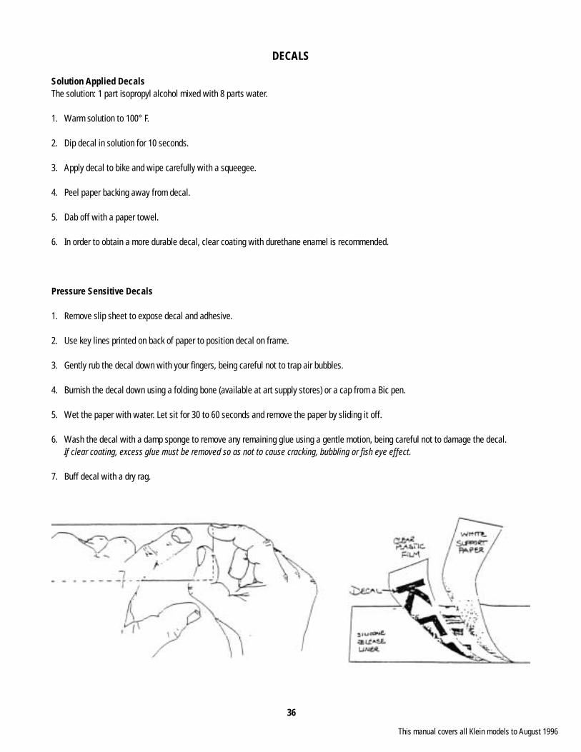
Pressure Sensitive Decals
1. Remove slip sheet to expose decal and adhesive.
2. Use key lines printed on back of paper to position decal on frame.
3. Gently rub the decal down with your fi ngers, being careful not to trap air bubbles.
4. Burnish the decal down using a folding bone (available at art supply stores) or a cap from a Bic pen.
5. Wet the paper with water. Let sit for 30 to 60 seconds and remove the paper by sliding it off.
6. Wash the decal with a damp sponge to remove any remaining glue using a gentle motion, being careful not to damage the decal. If clear coating, excess glue must be removed so as not to cause cracking, bubbling or fi sh eye effect.
7. Buff decal with a dry rag.
This manual covers all Klein models to August 1996

37
RACK APPLICATION
Blackburn Racks (408) 370-1010
Performance 54cm - 60cm Blackburn SX-1
Performance 52cm and 62cm Blackburn Mtn-1
Panache 47cm and 50cm Blackburn Mtn-1
Pinnacle 18”, 19” and 20” Blackburn Mtn-3
Pinnacle 22” Blackburn Mtn-1
Fervor / Rascal (all sizes) Blackburn Clamp (available through any Blackburn dealer)
** Some customers may want to drill and tap a hole in the rear dropout in order to mount a rack. This will work; however, any frame failure caused by this modifi cation will not be covered under warranty.
** We do not recommend using clamps on the seat stay of the Adroit, Team Super or Stage due to the addition of boron reinforcements.
The upper attaching arms must be bent into position for correct adjustment of the Blackburn racks.
American Bicycle 7/8” Clamp (612) 251-1641
Rhode Gear (401) 941-1700
The Rhode Gear VR-100 will fi t the Performance using the standard arms and the Pinnacle using the long arms.
This manual covers all Klein models to August 1996
38
INSTALLING RIV-NUT INSERTS
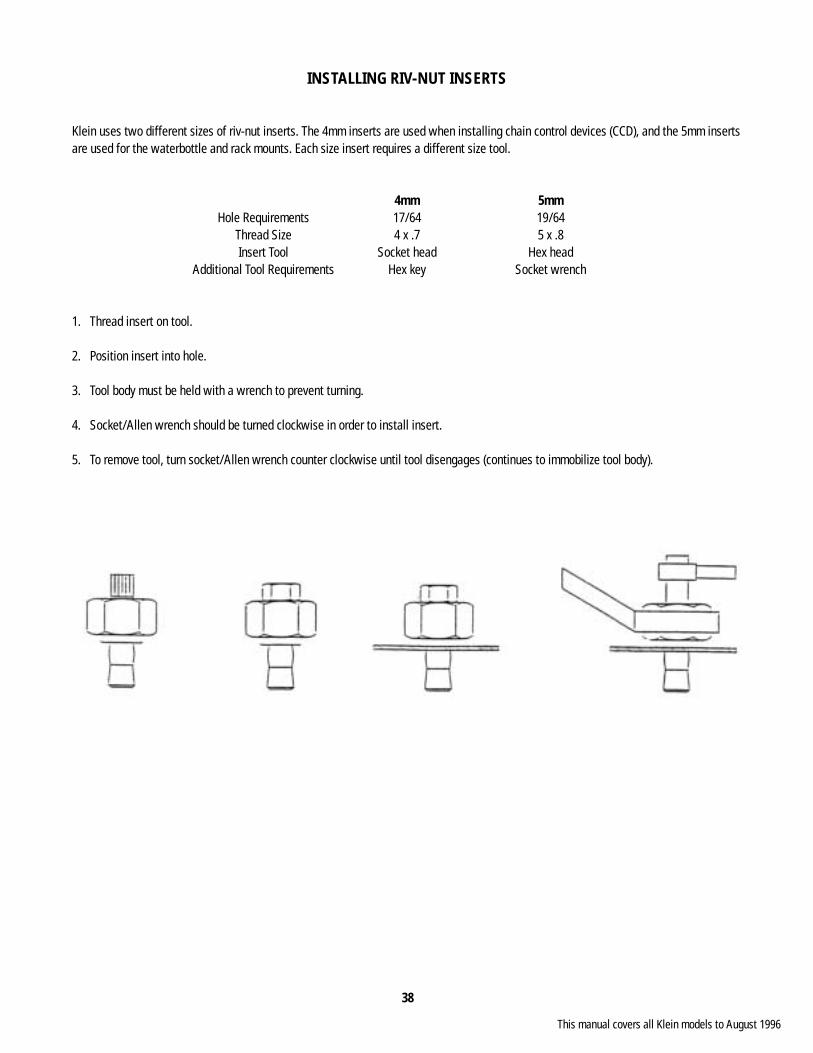
Klein uses two different sizes of riv-nut inserts. The 4mm inserts are used when installing chain control devices (CCD), and the 5mm inserts are used for the waterbottle and rack mounts. Each size insert requires a different size tool.
4mm 5mm Hole Requirements 17/64 19/64 Thread Size 4 x .7 5 x .8 Insert Tool Socket head Hex head Additional Tool Requirements Hex key Socket wrench
1. Thread insert on tool.
2. Position insert into hole.
3. Tool body must be held with a wrench to prevent turning.
4. Socket/Allen wrench should be turned clockwise in order to install insert.
5. To remove tool, turn socket/Allen wrench counter clockwise until tool disengages (continues to immobilize tool body).
This manual covers all Klein models to August 1996
39
S.I.S. UPDATE
S.I.S. update for u-brake mountain bike frames to re-route the rear cable outside the chain stay.
Tools Needed#33 drill bit, #30 drill bit, epoxy, pop rivet tool
Material NeededU-brake S.I.S. cable guide, Two (2) pop rivets - 1/8” or .125, Two (2) brake spacers - 1 slotted, One (1) pop rivet - 7/64” or .109
Directions
1. Place the frame upside down in the repair stand.
2. Remove the rear derailleur cable and housing from the frame.
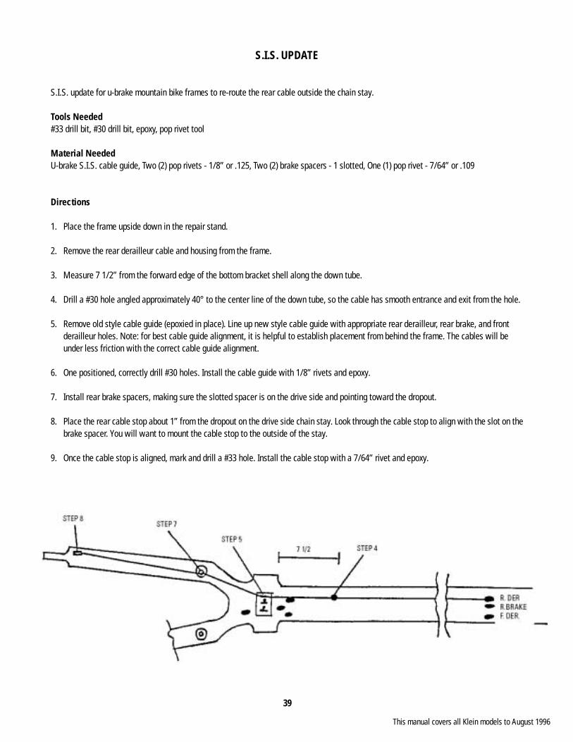
3. Measure 7 1/2” from the forward edge of the bottom bracket shell along the down tube.
4. Drill a #30 hole angled approximately 40° to the center line of the down tube, so the cable has smooth entrance and exit from the hole.
5. Remove old style cable guide (epoxied in place). Line up new style cable guide with appropriate rear derailleur, rear brake, and front derailleur holes. Note: for best cable guide alignment, it is helpful to establish placement from behind the frame. The cables will be under less friction with the correct cable guide alignment.
6. One positioned, correctly drill #30 holes. Install the cable guide with 1/8” rivets and epoxy.
7. Install rear brake spacers, making sure the slotted spacer is on the drive side and pointing toward the dropout.
8. Place the rear cable stop about 1” from the dropout on the drive side chain stay. Look through the cable stop to align with the slot on the brake spacer. You will want to mount the cable stop to the outside of the stay.
9. Once the cable stop is aligned, mark and drill a #33 hole. Install the cable stop with a 7/64” rivet and epoxy.
This manual covers all Klein models to August 1996
40
PACKAGING
FRAMES
DomesticFrames are packaged using cardboard to avoid shipping damage. Mission Control bar and stem are shipped with the frame.
Domestic DoubleFrames are packaged using foam supports.
InternationalFrames are packaged using foam to avoid shipping damage.
BOX DIMENSIONS
Frame
Single 9 x 45 x 31 14 lbs.
Double (Att/Adept only) 11 x 45 x 31 20 lbs.
Double (Other frames) 9 x 45 x 31 16 lbs.
Bottom Bracket Tool 9 x 9 x 6 4 lbs.
Headset Tool 30 x 4 x 3 8 lbs.
Mission Control 12 x 6 x 24 3 lbs.
(Packaged in foam, new version being developed)
BOX SPECIFICATIONS
Frame Boxes Longview Fiber 275 lb. tested Single B Grade
BB / Hs Tool Tharco 150 lb. tested Single B Grade
Mission Control Longview Fiber 175 lb. tested Single B Grade
This manual covers all Klein models to August 1996