kits 400 850 820 0, 400 850 821 0 and 400 850 052 2 ... · installation guide installing and ......
TRANSCRIPT

TP-08103Revised 01-17
Installation Guide
Installing and Configuring the Meritor WABCO Trailer ABS with
InfoLink™ Lift Axle Control OptionKits 400 850 820 0, 400 850 821 0 and 400 850 052 2
Must be used with the following Meritor WABCO InfoLink™-equipped ECU/Valve assemblies:
400 500 105 0 (2S/2M – 4S/2M), 400 500 106 0 (2S/1M)TP-08103Revised 01-171 Technical Bulletin
Hazard Alert MessagesRead and observe all Warning and Caution hazard alert messages in this publication. They provide information that can help prevent serious personal injury, damage to components, or both.
How to Obtain Additional Maintenance, Service and Product InformationRefer to Technical Bulletin TP-0685, PLC Display Kit Installation Instructions. Call the Meritor OnTrac™ Customer Call Center at 866-OnTrac1 (668-7221) to obtain this publication. Meritor WABCO publications are also available on our website:
meritorwabco.com
How to Obtain Tools, Kits and SuppliesTo obtain parts, call Meritor’s Commercial Vehicle Aftermarket at 888-725-9355.
NOTE: Application Sheet WT-0212 (single trailers) or WT-0213 (double trailers) must be completed and submitted to Meritor WABCO Trailer Engineering for approval prior to installing the Lift Axle Control Kit. This will allow Meritor WABCO to assist the trailer builder in determining lift and lower pressure values in order to achieve the desired performance. Pressure load curves are obtained directly from the suspension manufacturer, not Meritor WABCO. Application Sheets WT-0212 and WT-0213 can be found at meritorwabco.com.
Kit 400 850 820 0
� 463 084 050 0 — Lift axle control valve
� 449 518 030 0 — 3-meter solenoid valve cable
� 449 442 010 0 — Multiple generic I/O cable
� 441 044 106 0 — Pressure sensor
� 431 700 002 0 — Pressure switch
� TP-09174 — Label
Kit 400 850 821 0
� 463 084 050 0 — Lift axle control valve
� 449 518 030 0 — 3-meter solenoid valve cable
� 449 442 010 0 — Multiple generic I/O cable
� 449 428 030 0 — 12-volt analog input cable
� 441 044 106 0 — Pressure sensor
� TP-09174 — Label
Kit 400 850 052 2
� 463 084 050 0 — Lift axle control valve
� 449 518 030 0 — 3-meter solenoid valve cable
� 449 442 010 0 — Multiple generic I/O cable
� 449 428 030 0 — 12-volt analog input cable
� 441 044 106 0 — Pressure sensor
� 431 700 002 0 — Pressure switch
� 894 601 100 0 — ABS lift axle “Y” cable
� TP-09174 — Label
� MISC-13124 — Installation Guide link
NOTE: Please ensure the kits meet government regulations and local ordinances where the trailer will be in service.
NOTE: The Meritor WABCO Lift Axle Control option requires constant power to the trailer.
Other Components Sold Separately
� Optional, 400 850 411 0 — PLC Display
� Optional, 449 711 018 0 — 1.8-meter light output cable
� Optional, 449 711 031 0 — 3.1-meter light output cable
� Optional, 449 711 060 0 — 6-meter light output cable
� Optional, 449 711 120 0 — 12-meter light output cable

TP-08103Revised 01-17 (16579)Page 2 Copyright Meritor, Inc., 2017 Printed in USA
� Optional, 449 428 030 0 — 3-meter analog extension cable
� Optional, 449 428 060 0 — 6-meter analog extension cable
� Optional, 449 428 110 0 — 11-meter analog extension cable
� Optional, 449 425 030 0 — 3-meter analog extension cable
� Optional, 449 425 060 0 — 6-meter analog extension cable
� Optional, 449 425 110 0 — 11-meter analog extension cable
IntroductionThe Meritor WABCO Trailer ABS InfoLink™ Lift Axle Control Option uses the generic I/O capability to control the lift axle function of a trailer.
Kit 400 850 820 0 is a fully automatic system that uses a combination of switch input and lifting and lowering pressures all preset by the trailer manufacturer using the Meritor WABCO TOOLBOX™ Software. The system senses the load and raises or lowers the lift axle based on preset air pressure set by the trailer manufacturer. When the lift axle control valve is active and raises the axle, an optional light output on the trailer is activated to signal to the driver that the lift axle is in the “raised” position.
Kit 400 850 820 0 contains hardware for a fully automatic feature that will keep the lift axle in the lowered position when the spring brakes are applied.
Kit 400 850 821 0 is a fully automatic system that uses a combination of switch input and lifting and lowering pressures all preset by the trailer manufacturer using the Meritor WABCO TOOLBOX™ Software. The system senses the load and raises or lowers the lift axle based on preset air pressure set by the trailer manufacturer. When the lift axle control valve is active and raises the axle, an optional light output on the trailer is activated to signal to the driver that the lift axle is in the “raised” position.
Kit 400 850 821 0 contains hardware for a manual switch feature that will keep the lift axle in the lowered position.
Kit 400 850 052 2 is a lift axle system that features both automatic and manual override modes.
This lift axle configuration monitors axle load in order to raise or lower the axle without driver intervention. The system senses the load and raises or lowers the lift axle based on preset suspension air pressures set by the trailer manufacturer. When the lift axle control valve is active and raises the axle, an optional light output on the trailer is activated to signal the driver that the lift axle is in the "raised" position.
Whenever the vehicle is at rest and the spring brake is applied, the lift axle will move to the down position regardless of vehicle load. When the spring brake is released, the lift axle will move to the load appropriate position.
This kit also contains the required cables for a manual override switch that allows the vehicle operator to keep the lift axle in the down position regardless of vehicle load. Please refer to the local governing ordinances.
NOTE: Kits 400 850 820 0, 400 850 821 0 and 400 850 052 2 must be used with Meritor WABCO InfoLink™-equipped ECU/Valve assemblies 400 500 105 0 (2S/2M-4S/2M) or 400 500 106 0 (2S/1M).
The PLC Display by Meritor WABCO mounts to the vehicle’s instrument panel enabling the driver to monitor the status of the lift axle. Installation of the PLC display is covered in TP-0685, PLC Display Kit Installation Instructions. Figure 1.
Figure 1
Refer to the instructions in this technical bulletin for installing the Meritor WABCO Trailer ABS with InfoLink™ Lift Axle Control Option.
Configuration of Lift Axles by FunctionalityThe Lift Axle function may be configured in three different ways. Each method has its own specific hardware requirement and installation.
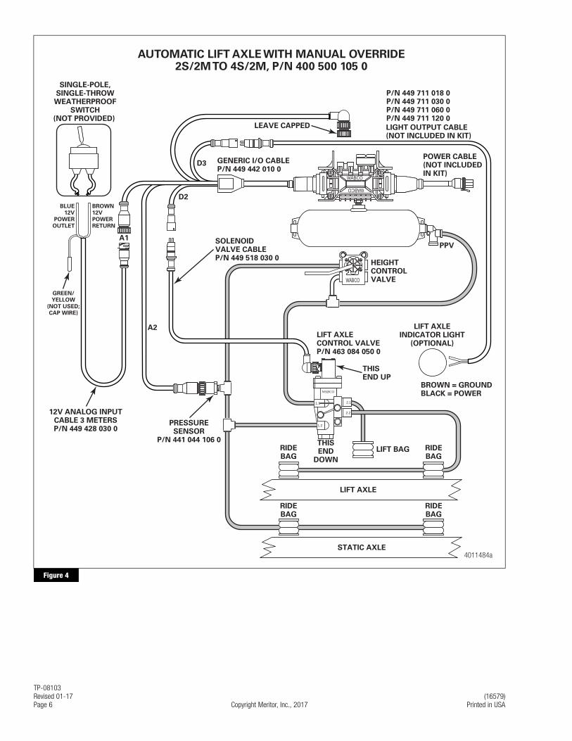
A. Automatic Lift Axle with Manual Override Switch (No spring brake delivery line pressure switch used). Kit number 400 850 821 0
This configuration allows the lift axle to automatically raise and lower based upon values put into TOOLBOX™ Software which are downloaded into the ECU when it is programmed. This configuration has a trailer-mounted manual override switch that allows the driver to disable the ECU controlled raise/lower function and keep the lift axle in the down position. This configuration allows the driver to keep the trailer in compliance where local ordinances require all lift axles to be kept in the down position regardless of load carried. Refer to Figure 2 for 2S/1M ECUs and Figure 4 for 2S/2M-4S/2M ECUs.
Figure 1
4007046b
GOOD
WARNING ALARMLift Axle

TP-08103(16579) Revised 01-17Printed in USA Copyright Meritor, Inc., 2017 Page 3
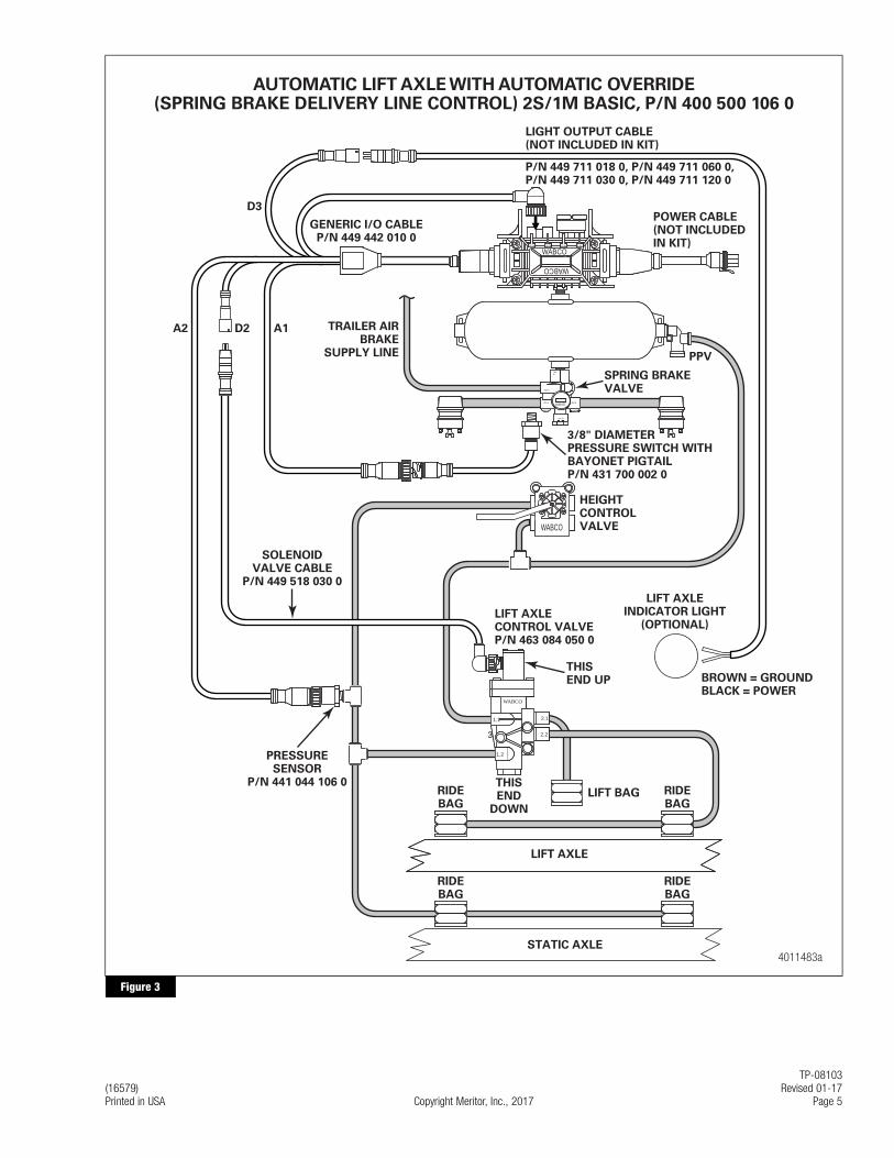
B. Automated Lift Axle with Automatic Override (Spring brake delivery line pressure switch required). Kit number 400 850 820 0
This configuration allows the lift axle to automatically raise and lower based upon values put into TOOLBOX™ Software which are downloaded into the ECU when it is programmed. This configuration allows the driver to lower the lifted axle when parked by pulling the red dash valve in the tractor to remove trailer supply air. This feature is useful for slider positioning or fast loading operations to ensure that the lift axle is in the down position. Specifically, when the delivery line from the trailer spring brake chamber meets or drops below 70 psi (4.82 bar), the ECU will automatically lower the lift axle. Refer to Figure 3 for 2S/1M ECUs and Figure 5 for 2S/2M-4S/2M ECUs.
C. Automated Lift Axle with Both Manual and Automatic Override. Kit number 450 850 052 2.
This configuration allows the driver to lower the lifted axle by means of a toggle switch or by pulling the red dash valve in the tractor to remove trailer supply air when the vehicle is at rest. The technician will perform the installation instructions for both manual and automatic configurations outlined in Step 10. Refer to Figure 6 for the installation diagram.
NOTE: A lift axle can be lowered by removing power to the trailer.
Installation
WARNINGTo prevent serious eye injury, always wear safe eye protection when you perform vehicle maintenance or service.
Remove all pressure from the air system before you disconnect any component. Pressurized air can cause serious personal injury.
Park the vehicle on a level surface. Block the wheels to prevent the vehicle from moving. Support the vehicle with safety stands. Do not work under a vehicle supported only by jacks. Jacks can slip and fall over. Serious personal injury and damage to components can result.
Ensure the trailer has correct electrical grounding; refer to SAE Specification J1908.
When you work on an electrical system, the possibility of electrical shock exists, and sparks can ignite flammable substances. You must always disconnect the battery ground cable before you work on an electrical system to prevent serious personal injury and damage to components.
1. Wear safe eye protection.
2. Park the vehicle on a level surface. Block the wheels to prevent the vehicle from moving.
NOTE: The trailer must not be loaded during this component installation.
3. Drain the brake and suspension systems of air before starting this procedure.
4. Disconnect the electrical power before starting this procedure.
5. Connect the multiple generic I/O cable, part number 449 442 010 0, into the ECU’s modulator connector port and secure it with the locking tab. Refer to Figure 2, Figure 3 and Figure 7 for the 2S/1M Basic ECU or Figure 4, Figure 5 and Figure 6 for the 2S/2M to 4S/2M Premium ECU, depending on the functionality selected.

TP-08103Revised 01-17 (16579)Page 4 Copyright Meritor, Inc., 2017 Printed in USA
Figure 2
Figure 2
4011482aWABCO
WABCO
YE 2/6YE 1/4BU 1/3BU 2/5
WABCO
3 88
1.1
1.2
2.1
2.2
WABCO
SINGLE-POLE,SINGLE-THROWWEATHERPROOF
SWITCH(NOT PROVIDED)
BLUE
12V
POWER
OUTLET
BROWN
12V
POWER
RETURN
A1
A2
GENERIC I/O CABLEP/N 449 442 010 0
LIGHT OUTPUT CABLE(NOT INCLUDED IN KIT)
POWER CABLE(NOT INCLUDED IN KIT)
PPV
HEIGHTCONTROLVALVE
LIFT AXLEINDICATOR LIGHT
(OPTIONAL)
D2
D3
GREEN/
YELLOW
(NOT USED;
CAP WIRE)
AUTOMATIC LIFT AXLE WITH MANUAL OVERRIDE2S/1M BASIC, P/N 400 500 106 0
RIDEBAG
RIDEBAG
RIDEBAG
RIDEBAG
LIFT BAG
LIFT AXLECONTROL VALVEP/N 463 084 050 0
THISEND UP
THISEND
DOWN
LIFT AXLE
STATIC AXLE
PRESSURESENSOR
P/N 441 044 106 0
BROWN = GROUNDBLACK = POWER
SOLENOIDVALVE CABLEP/N 449 518 030 0
12V ANALOG INPUTCABLE 3 METERSP/N 449 428 030 0
P/N 449 711 018 0P/N 449 711 030 0P/N 449 711 060 0P/N 449 711 120 0
TP-08103(16579) Revised 01-17Printed in USA Copyright Meritor, Inc., 2017 Page 5
Figure 3
Figure 3
4011483a
WABCO
WABCO
YE 2/6YE 1/4BU 1/3BU 2/5
WABCO
3 88
1.1
1.2
WABCO
sup 6
del 6
del 6
del 6
del 6
res8
con 6
110800
AUTOMATIC LIFT AXLE WITH AUTOMATIC OVERRIDE(SPRING BRAKE DELIVERY LINE CONTROL) 2S/1M BASIC, P/N 400 500 106 0
D3
A1 TRAILER AIRBRAKE
SUPPLY LINE
GENERIC I/O CABLEP/N 449 442 010 0
SPRING BRAKEVALVE
3/8" DIAMETERPRESSURE SWITCH WITHBAYONET PIGTAILP/N 431 700 002 0
HEIGHTCONTROL VALVE
LIFT AXLEINDICATOR LIGHT
(OPTIONAL)
POWER CABLE(NOT INCLUDEDIN KIT)
LIGHT OUTPUT CABLE(NOT INCLUDED IN KIT)
P/N 449 711 018 0, P/N 449 711 060 0,P/N 449 711 030 0, P/N 449 711 120 0
PPV
D2A2
2.1
2.2
RIDEBAG
RIDEBAG
RIDEBAG
RIDEBAG
LIFT BAG
LIFT AXLECONTROL VALVEP/N 463 084 050 0
PRESSURESENSOR
P/N 441 044 106 0
THISEND UP BROWN = GROUND
BLACK = POWER
THISEND
DOWN
LIFT AXLE
STATIC AXLE
SOLENOIDVALVE CABLE
P/N 449 518 030 0
TP-08103Revised 01-17 (16579)Page 6 Copyright Meritor, Inc., 2017 Printed in USA
Figure 4
Figure 4
4011484aWABCO
WABCO
YE 2/6YE 1/4BU 1/3BU 2/5
WABCO
3 88
1.1
1.2
2.1
2.2
WABCO
SINGLE-POLE,SINGLE-THROWWEATHERPROOF
SWITCH(NOT PROVIDED)
BLUE
12V
POWER
OUTLET
BROWN
12V
POWER
RETURN
A1
A2
GENERIC I/O CABLEP/N 449 442 010 0
LIGHT OUTPUT CABLE(NOT INCLUDED IN KIT)
POWER CABLE(NOT INCLUDED IN KIT)
PPV
HEIGHTCONTROLVALVE
LIFT AXLEINDICATOR LIGHT
(OPTIONAL)
D2
D3
GREEN/
YELLOW
(NOT USED;
CAP WIRE)
AUTOMATIC LIFT AXLE WITH MANUAL OVERRIDE2S/2M TO 4S/2M, P/N 400 500 105 0
RIDEBAG
RIDEBAG
RIDEBAG
RIDEBAG
LIFT BAG
LIFT AXLECONTROL VALVEP/N 463 084 050 0
THISEND UP
THISEND
DOWN
LIFT AXLE
STATIC AXLE
PRESSURESENSOR
P/N 441 044 106 0
BROWN = GROUNDBLACK = POWER
SOLENOIDVALVE CABLEP/N 449 518 030 0
LEAVE CAPPED
12V ANALOG INPUTCABLE 3 METERSP/N 449 428 030 0
P/N 449 711 018 0P/N 449 711 030 0P/N 449 711 060 0P/N 449 711 120 0

TP-08103(16579) Revised 01-17Printed in USA Copyright Meritor, Inc., 2017 Page 7
Figure 5
Figure 5
WABCO
WABCO
YE 2/6YE 1/4BU 1/3BU 2/5
4011485a
WABCO
3 88
1.1
1.2
WABCO
sup 6
del 6
del 6
del 6
del 6
res8
con 6
110800
AUTOMATIC LIFT AXLE WITH AUTOMATIC OVERRIDE(SPRING BRAKE DELIVERY LINE CONTROL) 2S/2M TO 4S/2M
P/N 400 500 105 0
D3
A1 TRAILER AIRBRAKE
SUPPLY LINE
LEAVE CAPPED
GENERIC I/O CABLEP/N 449 442 010 0
SPRING BRAKEVALVE
3/8" DIAMETERPRESSURE SWITCH WITHBAYONET PIGTAILP/N 431 700 002 0
HEIGHTCONTROL VALVE
LIFT AXLEINDICATOR LIGHT
(OPTIONAL)
POWER CABLE(NOT INCLUDEDIN KIT)
LIGHT OUTPUT CABLE(NOT INCLUDED IN KIT)
P/N 449 711 018 0P/N 449 711 030 0P/N 449 711 060 0P/N 449 711 120 0
PPV
D2A2
2.1
2.2
RIDEBAG
RIDEBAG
RIDEBAG
RIDEBAG
LIFT BAG
LIFT AXLECONTROL VALVEP/N 463 084 050 0
PRESSURESENSOR
P/N 441 044 106 0
THISEND UP BROWN = GROUND
BLACK = POWER
THISEND
DOWN
LIFT AXLE
STATIC AXLE
SOLENOIDVALVE CABLE
P/N 449 518 030 0

TP-08103Revised 01-17 (16579)Page 8 Copyright Meritor, Inc., 2017 Printed in USA
Figure 6
Figure 6
4012527a
WABCO
3 88
1.1
1.2
WABCO
sup 6
del 6
del 6
del 6
del 6
res8
con 6
110800
AUTOMATIC LIFT AXLE WITH AUTOMATIC AND MANUAL OVERRIDE(SPRING BRAKE DELIVERY LINE CONTROL) 4S/2M, P/N 400 500 105 0
D3
A1TRAILER AIR
BRAKESUPPLY LINE
GENERIC I/O CABLEP/N 449 442 010 0
LEAVE CAPPED
SPRING BRAKEVALVE
3/8" DIAMETERPRESSURE SWITCH WITHBAYONET PIGTAILP/N 431 700 002 0
HEIGHTCONTROL VALVE
LIFT AXLEINDICATOR LIGHT
(OPTIONAL)
POWER CABLE(NOT INCLUDEDIN KIT)
LIGHT OUTPUT CABLE (NOT INCLUDED IN KIT)
P/N 449 711 018 0, P/N 449 711 060 0,P/N 449 711 030 0, P/N 449 711 120 0
PPV
D2
A2
2.1
2.2
RIDEBAG
RIDEBAG
RIDEBAG
RIDEBAG
LIFT BAG
LIFT AXLECONTROL VALVEP/N 463 084 050 0
PRESSURESENSOR
P/N 441 044 106 0
THISEND UP
BROWN = GROUNDBLACK = POWER
THISEND
DOWN
LIFT AXLE
STATIC AXLE
SOLENOIDVALVE CABLE
P/N 449 518 030 0
"Y" CABLEP/N 894 601 100 0
SINGLE-POLE,SINGLE-THROWWEATHERPROOF
SWITCH(NOT PROVIDED)
BLUE
12V
POWER
OUTLET
BROWN
12V
POWER
RETURN
GREEN/
YELLOW
(NOT USED;
CAP WIRE)
12V ANALOG INPUT CABLE
3 METERSP/N 449 428 030 0

TP-08103(16579) Revised 01-17Printed in USA Copyright Meritor, Inc., 2017 Page 9
Figure 7
Figure 7
4012611a
WABCO
3 88
1.1
1.2
WABCO
sup 6
del 6
del 6
del 6
del 6
res8
con 6
110800
AUTOMATIC LIFT AXLE WITH AUTOMATIC AND MANUAL OVERRIDE(SPRING BRAKE DELIVERY LINE CONTROL) 2S/1M, P/N 400 500 106 0
D3
A1 TRAILER AIRBRAKE
SUPPLY LINE
GENERIC I/O CABLEP/N 449 442 010 0
SPRING BRAKEVALVE
3/8" DIAMETERPRESSURE SWITCH WITHBAYONET PIGTAILP/N 431 700 002 0
HEIGHTCONTROL VALVE
LIFT AXLEINDICATOR LIGHT
(OPTIONAL)
POWER CABLE(NOT INCLUDEDIN KIT)
LIGHT OUTPUT CABLE (NOT INCLUDED IN KIT)
P/N 449 711 018 0, P/N 449 711 060 0,P/N 449 711 030 0, P/N 449 711 120 0
PPV
D2
A2
2.1
2.2
RIDEBAG
RIDEBAG
RIDEBAG
RIDEBAG
LIFT BAG
LIFT AXLECONTROL VALVEP/N 463 084 050 0
PRESSURESENSOR
P/N 441 044 106 0
THISEND UP
BROWN = GROUNDBLACK = POWER
THISEND
DOWN
LIFT AXLE
STATIC AXLE
SOLENOIDVALVE CABLE
P/N 449 518 030 0
"Y" CABLEP/N 894 601 100 0
SINGLE-POLE,SINGLE-THROWWEATHERPROOF
SWITCH(NOT PROVIDED)
BLUE
12V
POWER
OUTLET
BROWN
12V
POWER
RETURN
GREEN/
YELLOW
(NOT USED;
CAP WIRE)
12V ANALOG INPUT CABLE
3 METERSP/N 449 428 030 0
WABCO
WABCO

TP-08103Revised 01-17 (16579)Page 10 Copyright Meritor, Inc., 2017 Printed in USA
6. Connect the solenoid valve cable, part number 449 518 030 0 to the “D2” digital output of the multiple generic I/O cable. NOTE: “D2” lettering is stamped in white on the female end of the multiple generic I/O cable. Refer to Figure 2, Figure 3 and Figure 7 for the 2S/1M Basic ECU or Figure 4, Figure 5 and Figure 6 for the 2S/2M to 4S/2M Premium ECU, depending on the functionality selected.
7. Connect the lift axle control valve, part number 463 084 050 0, to the solenoid valve cable, part number 449 518 030 0. Refer to Figure 2, Figure 3 and Figure 7 for the 2S/1M Basic ECU or Figure 4, Figure 5 and Figure 6 for the 2S/2M to 4S/2M Premium ECU, depending on the functionality selected.
8. Ensure that the lift axle control valve is installed correctly. Refer to Figure 8.
NOTE: A barrier of plastic or mylar should be placed between the lift axle control valve and the surface it will be mounted on. This will help inhibit potential corrosion between dissimilar metals.
Figure 8
9. The pressure sensor, part number 441 044 106 0, must be connected to the “A2” lead on the multiple generic I/O cable. The pressure sensor must be attached to the ride bag air circuit of the trailer’s air suspension in order to determine the load on the trailer.
10. Perform one of the following depending on the trailer you are servicing.
A. For Trailers with Both Manual and Automatic Lift Axle Override
Connect the single wire leg of the lift axle “Y” cable 894 601 100 0 to the “A1” lead of the generic I/O cable 449 442 010 0. This “Y” cable splits the “A1” lead of the generic I/O cable into two “A1” leads. The technician will then perform BOTH Steps 10 B and 10 C for configurations requiring both manual and automatic lift axle overrides.
B. For Trailers with Automatic Lift Axle Override
The pressure switch, part number 431 700 002 0, must be connected to the “A1” lead on the multiple generic I/O cable. The pressure switch must be connected between the delivery port of the spring brake valve and the spring brake chamber using a tee in the delivery line. When supply air is removed from the trailer, the pressure switch overrides the settings that govern the raise/lower feature and keeps the lift axle in the lowered position as long as the switch is activated. This is achieved by pulling the red dash valve in the towing vehicle to remove supply air from the trailer.
C. For Trailers with Manual Lift Axle Override
The analog input cable, part number 449 428 030 0, must be connected to the “A1” lead on the multiple generic I/O cable. The analog input cable must be connected to a single-pole, single-throw, weatherproof toggle switch that is mounted on the trailer in a driver-accessible location.
NOTE: This switch is not provided by Meritor WABCO. Ensure that the “on” and “off” positions are clearly labeled.
Connect the blue wire of the analog input cable to the one side of the toggle switch and the brown wire to the other side of the toggle switch. The green/yellow wire is not used and must be capped or terminated to prevent any corrosion. This switch overrides the settings that govern the raise/lower feature and keeps the lift axle in the lowered position as long as the switch is activated.
NOTE:“A1”, “A2”, “D2” and “D3” lettering are stamped in white on the female end of the multiple generic I/O cable. Refer to Figure 2, Figure 3 and Figure 7 for the 2S/1M Basic ECU or Figure 4, Figure 5 and Figure 6 for the 2S/2M to 4S/2M Premium ECU, depending on the functionality selected.
Figure 8
4007073a
2.1 – TO THELIFTING
AIR BAGS
2.2 – TO THERIDE CONTROLAIR BAGS OFTHE LIFTINGAXLE(S)
3.0 – EXHAUSTOUTLET
THIS SIDE UP
1.1 – SUPPLYPRESSURE
1.2 – FROM THESUSPENSIONAIR BAGS OF
THE NON-LIFTING AXLE(S)

TP-08103(16579) Revised 01-17Printed in USA Copyright Meritor, Inc., 2017 Page 11
11. Connect an optional light output cable to the “D3” digital output of the multiple generic I/O cable. (The light output cable is not part of the kit. Please choose the appropriate length for your application.) Refer to Figure 2 and Figure 3 for the 2S/1M Basic ECU or Figure 4 and Figure 5 for the 2S/2M to 4S/2M Premium ECU, depending on the functionality selected. Also, Meritor WABCO requires that an LED light or incandescent light of less than 1 amp is used. Ensure that the LED light has a load resistor across the positive and negative terminals. This information is provided by your light manufacturer.
12. Enter the lifting and lowering pressures using the following activation procedure.
Lift Axle Function Activation ProcedureThe following procedure is used to enter lifting and lowering pressures when the Lift Axle is selected in TOOLBOX™ Software.
NOTE: The Lift Axle function can only be enabled on premium ECUs (part numbers 400 500 105 0, 400 500 106 0).
1. Activate TOOLBOX™ Software on your PC. Select the Lift/Lower Pressures option from the Modify pull-down menu. Figure 9.
Figure 9
2. The Lift Axle Lowering/Lifting Pressures screen appears which allows you to enter the Lowering and Lifting Pressures. Figure 10.
Figure 10
Determining Lifting and Lowering Pressures
Values will be obtained from the suspension manufacturer and modified according to the customer’s performance expectations. Ensure these values comply with government regulations where the trailer will be in service.
Type the Lowering and Lifting Pressures in the fields provided. The values must fall within the following restrictions:
� Valid range: 5-100 psi
� Lowering Pressure must be greater than Lifting Pressure
� Lowering and Lifting pressures must differ by at least 15 psi
When the pressures have been entered, click OK.
3. The values are validated and programmed when the OK button is pressed. When a confirmation message appears, press the OK button to continue. Figure 11.
Figure 11
NOTE: If the values are out of range, a message will be displayed and the user will be prompted to fix the out-of-range value. This process will continue until the entered values can be validated or the Cancel button is selected. If you choose Cancel, you will be sent back to the main menu without modifying the pressure values in the ECU.
4. After the pressure values have been validated and programmed, they will be displayed in TOOLBOX™ Software’s “Notebook” feature. Figure 12.
Figure 9
Figure 10
4009820a
4008723a
80
35
Figure 11
4010314a

TP-08103Revised 01-17 (16579)Page 12 Copyright Meritor, Inc., 2017 Printed in USA
Figure 12
Loading TIO Files
Once raise and lower pressures are set in the Lift Axle Activation Procedure, there is no need to load a TIO file to gain this functionality. However, there may be instances where Meritor WABCO is asked to provide the customer with a customized TIO file to load into their trailers. These customized files will be provided electronically and must be copied into the following areas of the programming computer.
� XP with TOOLBOX™ Software 10.3.2 or earlier: C:\Program Files\WABCO\WINNT\Trailer
� XP with TOOLBOX™ Software 11.0 or higher: C:\Program Files\Meritor WABCO\TOOLBOX\Trailer
� Windows 7 with TOOLBOX™ Software 10.3.2 or earlier: C:\Program Files(x86)\WABCO\WINNT\Trailer
� Windows 7 with TOOLBOX™ Software 11.0 or higher: C:\Program Files (x86)\MeritorWABCO\ToolBox\Trailer
The step-by-step example displayed in this manual shows a file called LiftAxle.tio. This file name may be different depending upon the customer’s lift axle requirements.
1. From the opening screen of the ABS portion of TOOLBOX™ Software, activate the Modify pull-down menu and select the Download GIO Parameters menu option. Figure 13.
Figure 13
2. From the Parameter Download screen, select “LiftAxle.tio”. Press the Start button and it will enable the Download button. Press the Download button to begin the process. Figure 14.
Figure 14
3. After the TOOLBOX™ screen displays “Download Complete”, press Close and perform the Lift Axle Test. Figure 15.
Figure 12
4010041a
Figure 13
Figure 14
4011481a
4010312a

TP-08103(16579) Revised 01-17Printed in USA Copyright Meritor, Inc., 2017 Page 13
Figure 15
Lift Axle Test
The Lift Axle Test is performed after the ABS system has been properly programmed and the End of Line Test has been successfully performed.
The trailer must have constant power applied and have air supplied to the supply/emergency (red) line.
Activate the manual override switch to confirm that the lift axle lowers in an unladen state. Once confirmed, return the switch to its original position and the lift axle should raise.
Testing the configuration that has the delivery line pressure switch in place of the manual toggle switch requires a tractor. Correct operation should be tested after the trailer End of Line test has been completed. Attach the unladen trailer to a tractor and ensure both air and power are hooked up. Release the trailer spring brakes using the red trailer brake valve on the tractor dash. The lift axle should move to the raised position once the spring brake has released. Apply the spring brakes (evacuating air) using the red trailer brake valve on the tractor dash. The lift axle should lower. This completes the pressure switch test.
Add the appropriate amount of weight to the trailer so that the ride bag pressure equals or exceeds the “Lowering Pressure” value entered into the Parameter screen. The lift axle should lower from the raised position and the indicator lamp should extinguish.
This completes the Lift Axle Test.
Figure 15
4010313a

TP-08103Revised 01-17 (16579)Page 14 Copyright Meritor, Inc., 2017 Printed in USA
Lift Axle Test Rig
Some trailer OEMs may choose to construct an assembly to rapidly test the performance of automatic lift axle installations using the spring brake delivery line pressure switch. Components used in the construction of this assembly are commonly found at trailer OEM facilities. Figure 16.
Figure 16
Figure 16
4011345a
STANDARD MALE QUICKCOUPLER FITTING
PRESSUREREGULATORWITH GAUGE
FITTING
1/2" HOSE
1/2" TO 3/8"FITTING
PRESSURE SWITCHP/N 431 700 002 0
1/2" HOSE
SIMULATED AIRSUSPENSION LINE
1/2" TO 1/4"FITTING
PRESSURE SENSORP/N 441 044 106 0
CONNECTS TO "A2"ON GENERIC I/O CABLE
MERITOR WABCO431 700 002 0
XX XX/XX
FITTING
PSI
TEEFITTING
PRESSURE REGULATORWITH GAUGE
SIMULATEDSPRING BRAKELINE
(0-100 PSI)
PSI
(0-100 PSI)
CONNECTS TO "AI"ON GENERIC I/O CABLE

TP-08103(16579) Revised 01-17Printed in USA Copyright Meritor, Inc., 2017 Page 15
Using the Lift Axle Test Rig — Automatic Override
NOTE: Prior to beginning the test, the Meritor WABCO ABS with Lift Axle Control must be installed and have successfully completed the End of Line testing. Do not proceed without accomplishing this first.
1. Attach shop air to lift axle test rig “tee” fitting.
2. Connect the test rig’s pressure switch to the lead “A1” of the generic I/O cable.
3. Connect the test rig’s pressure sensor to the lead “A2” of the generic I/O cable.
4. Adjust pressure regulator attached to the pressure sensor on lead “A2” to 15 psi.
5. Adjust pressure regulator attached to the pressure switch on lead “A1” to 90 psi.
6. Increase the air pressure to the pressure sensor on lead “A2” to a psi level above the lift axle’s stated lowering pressure. The lift bags should deflate and the axle should lower.
7. Decrease the air pressure to the pressure sensor on lead “A2” to a psi level below the lift axle’s stated raising pressure. The lift bags should inflate and the axle should rise.
8. Decrease the air pressure to the pressure switch on lead “A1” to a level below 70 psi. The lift bags should deflate and the axle should lower.
9. Increase air pressure to the pressure switch on lead “A1” to a level above 70 psi. The lift bags should inflate and the axle should rise.
10. The test has been completed. Remove the “A1” and “A2” connections from the test rig. Re-attach the “A1” and “A2” connections to the sensor and switch installed on the trailer’s suspension.
Using the Lift Axle Test Rig — Manual Override
NOTE: Prior to beginning the test, the Meritor WABCO ABS with Lift Axle Control must be installed and have successfully completed the End of Line test. Do not proceed without accomplishing this first.
1. Attach shop air to lift axle test rig “tee” fitting.
2. Connect the test rig’s pressure sensor to the lead “A2” of the generic I/O cable.
3. Adjust pressure regulator attached to the pressure sensor on lead “A2” to 15 psi.
4. Ensure the manual override switch is in the deactivated (OFF) position.
5. Increase the air pressure to the pressure sensor on lead “A2” to a psi level above the lift axle’s stated lowering pressure. The lift bags should deflate and the axle should lower.
6. Decrease the air pressure to the pressure sensor on lead “A2” to a psi level below the lift axle’s stated raising pressure. The lift bags should inflate and the axle should rise.
7. Activate the manual override switch (switch to the ON position). The lift bags should deflate and the axle should lower.
8. Deactivate the manual override switch (switch to the OFF position). The lift bags should inflate and the axle should rise.
9. The test has been completed. Remove the “A2” connection from the test rig. Re-attach the “A2” connection to the sensor installed on the trailer’s suspension.
Lift Axle Label
The lifting and lowering pressures will be clearly written with indelible ink on label TP-09174. This label will be affixed near the lift axle on the trailer body by the trailer’s original equipment manufacturer. Figure 17.
Figure 17
Cable Strain Relief GuidelinesIt is important that cabling follow good strain relief practices to ensure maximum performance and durability. Failure to provide adequate strain relief on the cables can result in future maintenance not covered under warranty.
Strain relief is defined as a small amount of slack in the cable at the area of connection. This lack of cable tension allows for movement of the cable during times when components of the suspension and air system may be in motion. A small amount of slack also eases access to other system components.
Figure 17
4009796a

Information contained in this publication was in effect at the time the publication was approved for printing and is subject tochange without notice or liability. Meritor WABCO reserves the right to revise the information presented or to discontinue theproduction of parts described at any time.
Copyright 2017 TP-08103Meritor, Inc. Revised 01-17All Rights Reserved Printed in USA (16579)
Meritor WABCO Vehicle Control Systems2135 West Maple RoadTroy, MI 48084-7121 USA866-OnTrac1 (668-7221)meritorwabco.com
A taut cable can affect the lifespan of the cable. Cables without adequate strain relief can potentially stress a cable connection enough that moisture could intrude. Unnecessary wear at bend points can be the result of a cable under tension.
It is recommended that cable connections to a component, such as an ECU valve assembly, display a visible amount of slack in the cable up to the first tie or clip that secures the cable to trailer structure or airline. This first anchor point should be a minimum of 6-inches with a maximum of 12-inches from the cable/component connection. This applies to all sensor, power, valve and GIO cables. Figure 18.
Figure 18
When placing ties used for cable-to-cable connections, have at least a one-inch (25.4 mm) distance from the cable connector. Do not place a tie on the connector itself. Figure 19.
Figure 19
Figure 18
4011409a
SENSOR EXTENSIONCABLES WITH CORRECT
STRAIN RELIEF
Figure 19
SENSORCABLE
3"(76 MM)
4003573a