kit instructions
TRANSCRIPT
1
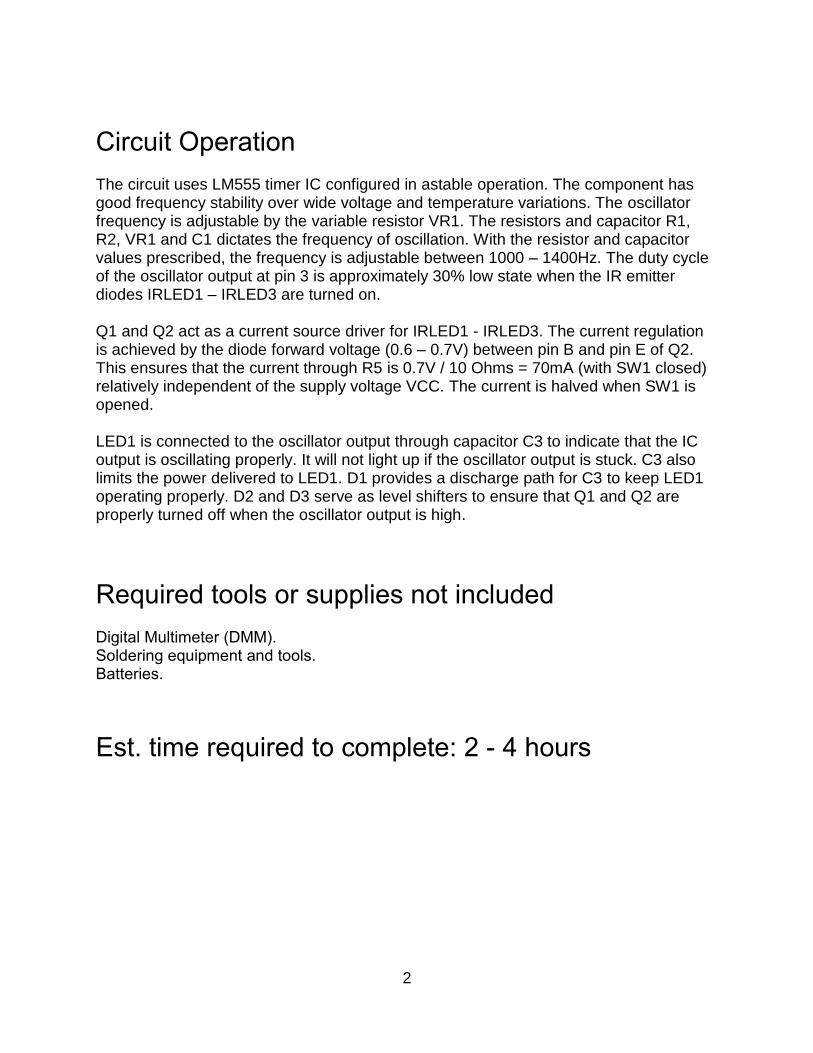
Infrared Beacon for Robotics This project is an Infrared (IR) beacon for use in some robotics games and competitions. It emits an IR signal at 1200Hz (adjustable ±200Hz) suitable for some IR sensors in robotics. It uses the LM555 timer IC and a two-transistor current source to drive IR emitting diodes. The device maintains stable frequency and IR output throughout a wide operating voltage from 4.5 – 9V independent of battery strength. A low/high switch selects longer battery life or higher IR output.
Circuit Schematics
2
Circuit Operation The circuit uses LM555 timer IC configured in astable operation. The component has good frequency stability over wide voltage and temperature variations. The oscillator frequency is adjustable by the variable resistor VR1. The resistors and capacitor R1, R2, VR1 and C1 dictates the frequency of oscillation. With the resistor and capacitor values prescribed, the frequency is adjustable between 1000 – 1400Hz. The duty cycle of the oscillator output at pin 3 is approximately 30% low state when the IR emitter diodes IRLED1 – IRLED3 are turned on. Q1 and Q2 act as a current source driver for IRLED1 - IRLED3. The current regulation is achieved by the diode forward voltage (0.6 – 0.7V) between pin B and pin E of Q2. This ensures that the current through R5 is 0.7V / 10 Ohms = 70mA (with SW1 closed) relatively independent of the supply voltage VCC. The current is halved when SW1 is opened. LED1 is connected to the oscillator output through capacitor C3 to indicate that the IC output is oscillating properly. It will not light up if the oscillator output is stuck. C3 also limits the power delivered to LED1. D1 provides a discharge path for C3 to keep LED1 operating properly. D2 and D3 serve as level shifters to ensure that Q1 and Q2 are properly turned off when the oscillator output is high.
Required tools or supplies not included Digital Multimeter (DMM). Soldering equipment and tools. Batteries.
Est. time required to complete: 2 - 4 hours
3
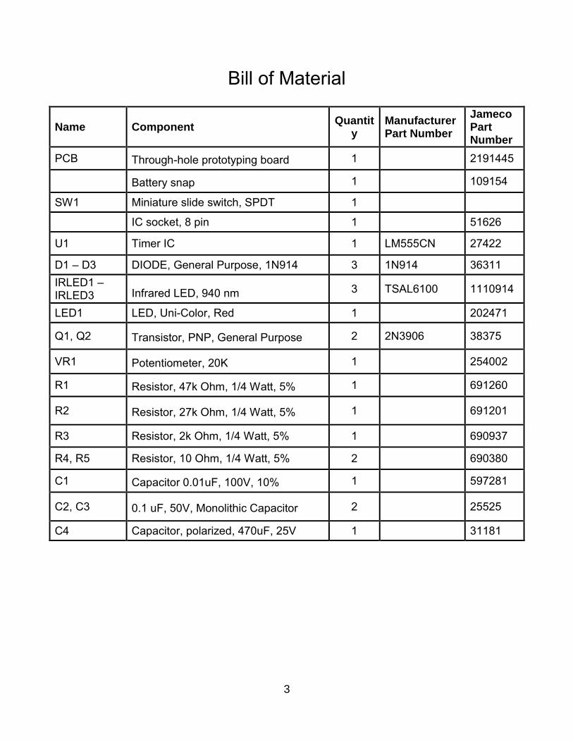
Bill of Material
Name Component Quantit
y Manufacturer Part Number
Jameco Part Number
PCB Through-hole prototyping board 1 2191445
Battery snap 1 109154
SW1 Miniature slide switch, SPDT 1
IC socket, 8 pin 1 51626
U1 Timer IC 1 LM555CN 27422
D1 – D3 DIODE, General Purpose, 1N914 3 1N914 36311
IRLED1 – IRLED3 Infrared LED, 940 nm 3 TSAL6100 1110914
LED1 LED, Uni-Color, Red 1 202471
Q1, Q2 Transistor, PNP, General Purpose 2 2N3906 38375
VR1 Potentiometer, 20K 1
254002
R1 Resistor, 47k Ohm, 1/4 Watt, 5% 1
691260
R2 Resistor, 27k Ohm, 1/4 Watt, 5% 1
691201
R3 Resistor, 2k Ohm, 1/4 Watt, 5% 1
690937
R4, R5 Resistor, 10 Ohm, 1/4 Watt, 5% 2 690380
C1 Capacitor 0.01uF, 100V, 10% 1
597281
C2, C3 0.1 uF, 50V, Monolithic Capacitor 2
25525
C4 Capacitor, polarized, 470uF, 25V 1 31181
4
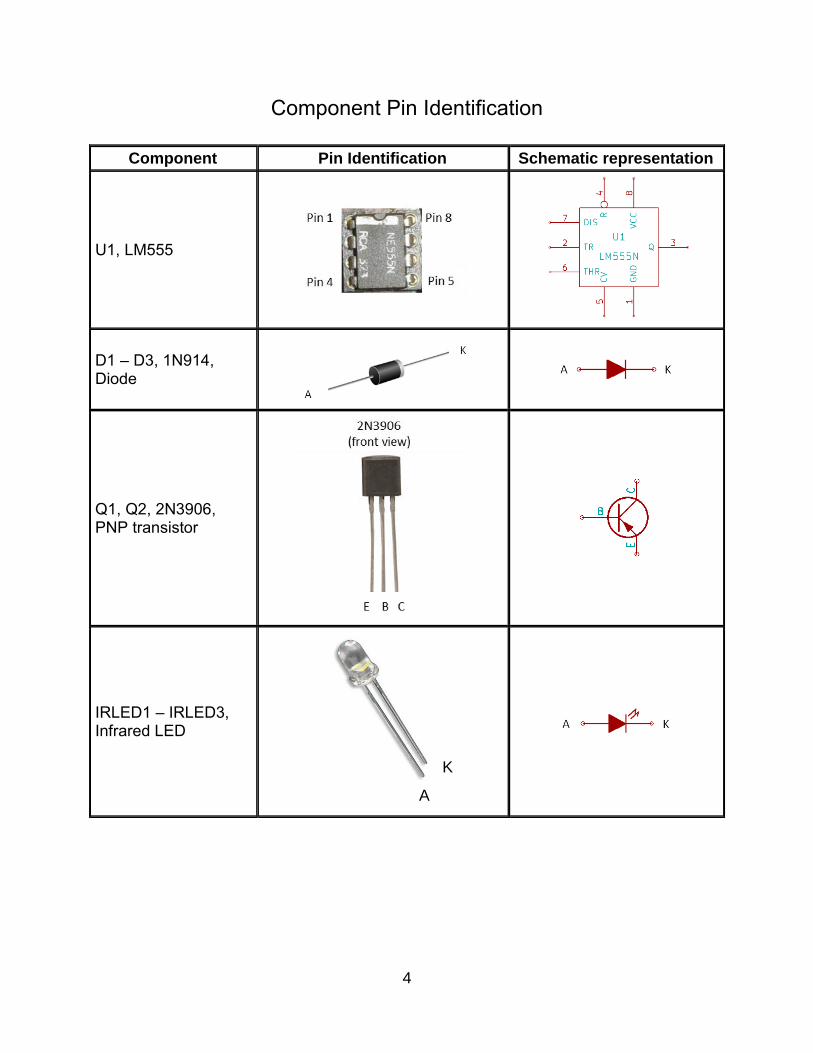
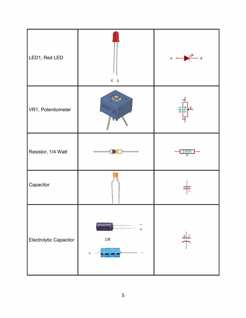
Component Pin Identification
Component Pin Identification Schematic representation
U1, LM555
D1 – D3, 1N914, Diode
Q1, Q2, 2N3906, PNP transistor
IRLED1 – IRLED3, Infrared LED
K
A
5
LED1, Red LED
VR1, Potentiometer
Resistor, 1/4 Watt
Capacitor
Electrolytic Capacitor
6
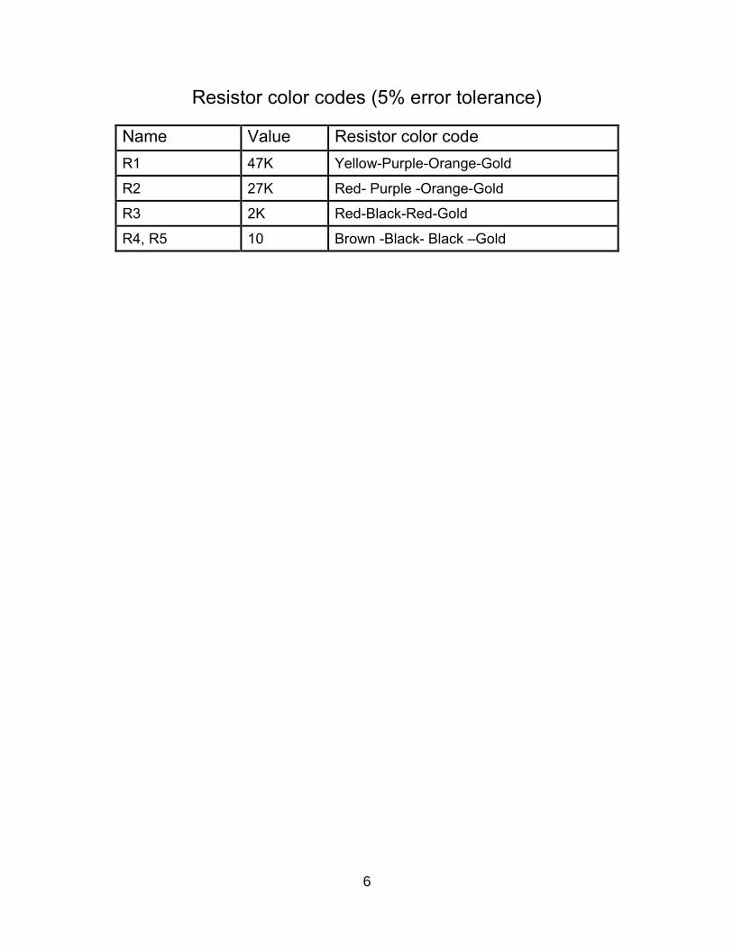
Resistor color codes (5% error tolerance)
Name Value Resistor color code
R1 47K Yellow-Purple-Orange-Gold
R2 27K Red- Purple -Orange-Gold
R3 2K Red-Black-Red-Gold
R4, R5 10 Brown -Black- Black –Gold
7
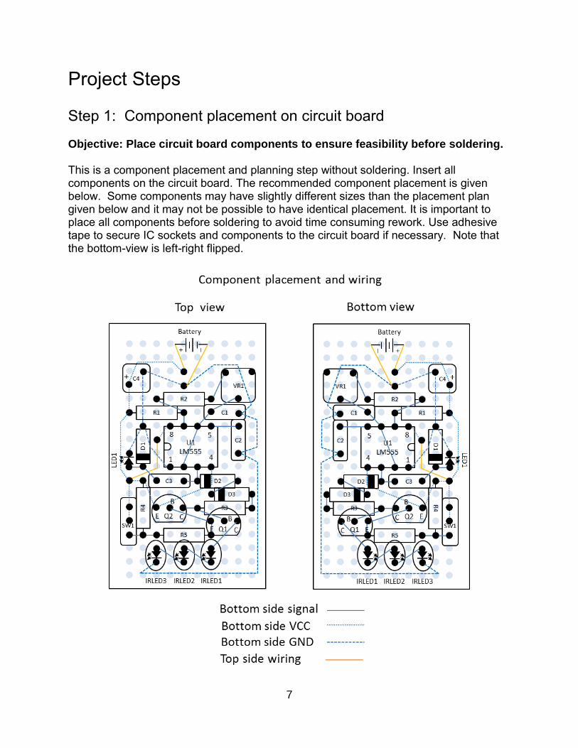
Project Steps Step 1: Component placement on circuit board Objective: Place circuit board components to ensure feasibility before soldering. This is a component placement and planning step without soldering. Insert all components on the circuit board. The recommended component placement is given below. Some components may have slightly different sizes than the placement plan given below and it may not be possible to have identical placement. It is important to place all components before soldering to avoid time consuming rework. Use adhesive tape to secure IC sockets and components to the circuit board if necessary. Note that the bottom-view is left-right flipped.
8
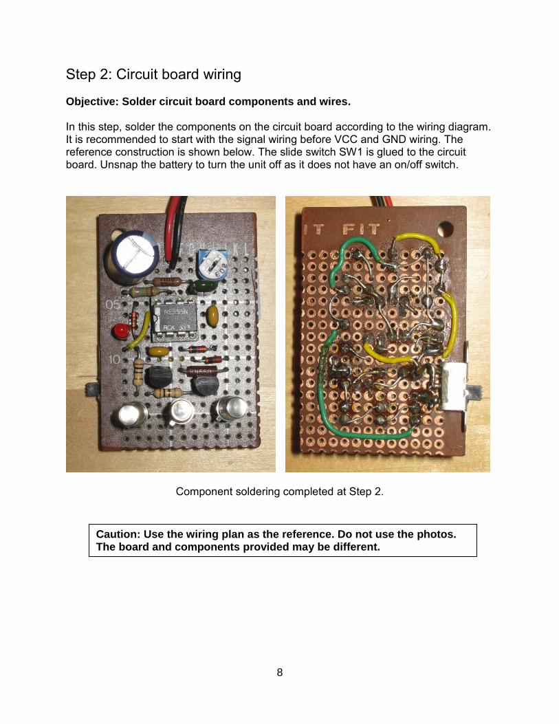
Step 2: Circuit board wiring Objective: Solder circuit board components and wires. In this step, solder the components on the circuit board according to the wiring diagram. It is recommended to start with the signal wiring before VCC and GND wiring. The reference construction is shown below. The slide switch SW1 is glued to the circuit board. Unsnap the battery to turn the unit off as it does not have an on/off switch.
Component soldering completed at Step 2.
Caution: Use the wiring plan as the reference. Do not use the photos. The board and components provided may be different.
9
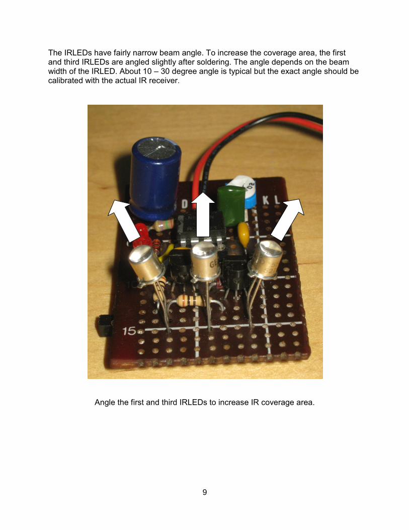
The IRLEDs have fairly narrow beam angle. To increase the coverage area, the first and third IRLEDs are angled slightly after soldering. The angle depends on the beam width of the IRLED. About 10 – 30 degree angle is typical but the exact angle should be calibrated with the actual IR receiver.
Angle the first and third IRLEDs to increase IR coverage area.

10
Step 3: Test and troubleshoot Objective: Test the individual parts of the system. Follow the test procedure in the order described below. Resolve the test failures before proceeding to the next test.
Test 1: Power supply on IC socket. This test is conducted with the LM555 removed from the socket. Apply 6V battery power and measure the following pin voltages with respect to GND:
LM555 socket pin Measured Voltage
Note
1. GND 0V System ground.
2. TRIGGER 6V Connected to VCC though R1, R2 and VR1. The measured voltage may be slightly less than VCC depending on the DMM.
3. OUTPUT No test
4. RESET 6V Connected to VCC.
5. CONTROL No test
6. THRESHOLD 6V Same as pin 2.
7. DISCHARGE 6V Connected to VCC though R1. The measured voltage may be slightly less than VCC depending on the DMM.
8. VCC 6V System power supply.
11
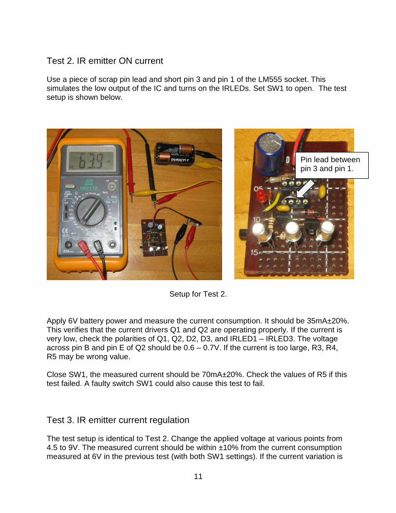
Test 2. IR emitter ON current Use a piece of scrap pin lead and short pin 3 and pin 1 of the LM555 socket. This simulates the low output of the IC and turns on the IRLEDs. Set SW1 to open. The test setup is shown below.
Setup for Test 2. Apply 6V battery power and measure the current consumption. It should be 35mA±20%. This verifies that the current drivers Q1 and Q2 are operating properly. If the current is very low, check the polarities of Q1, Q2, D2, D3, and IRLED1 – IRLED3. The voltage across pin B and pin E of Q2 should be 0.6 – 0.7V. If the current is too large, R3, R4, R5 may be wrong value. Close SW1, the measured current should be 70mA±20%. Check the values of R5 if this test failed. A faulty switch SW1 could also cause this test to fail.
Test 3. IR emitter current regulation The test setup is identical to Test 2. Change the applied voltage at various points from 4.5 to 9V. The measured current should be within ±10% from the current consumption measured at 6V in the previous test (with both SW1 settings). If the current variation is
Pin lead between pin 3 and pin 1.
12
large, Q1 and Q2 current regulation has failed. Check the polarities of Q1, Q2, D2, D3 and the values of R3, R4, and R5. The voltage across pin B and pin E of Q1 should be 0.6 – 0.7V when VCC is anywhere between 4.5 – 9V.
Test 4. IR emitter OFF current Use a piece of scrap pin lead to connect pin 3 and pin 8 of the LM555 socket. This simulates the high output of the IC and turns off the IRLEDs. Apply 6V battery power and measure the current consumption. It should be less than 1mA regardless of whether SW1 is open or close. This verifies that the Q1 and Q2 are properly turned off. Check the polarities of Q1, Q2, D2, D3 and IRLED1 – IRLED3 and trace the current path if this test fails.
Test 5: Complete circuit operation. Install LM555 and dial VR1 to the center position. Apply 6V battery power and measure the current consumption with SW1 closed. The current should be 25mA±20%. With SW1 opened, the current should decrease about 45%. LED1 should be lit indicating the oscillator output signal. If LED1 is off, check the polarities of D1 and LED1. If the LED1 is verified, the fault could be with the oscillator. Measure the voltage of the oscillator output at pin 3. It should be about 70% of VCC. If it is stuck at a low or high state, the LM555 oscillator has failed. Check the wiring of the IC and the values of R1, R2, VR1, C1 and C2. Pin 4 should be at high and pin 5 should be at 2/3 of VCC for proper operations of LM555. If you have an oscilloscope, measure the oscillator output pin 3 and you should see a square wave output swinging between 0 to VCC, with about 70% output high duty cycle. The oscillation frequency is adjustable by VR1 from 1000 – 1400Hz.
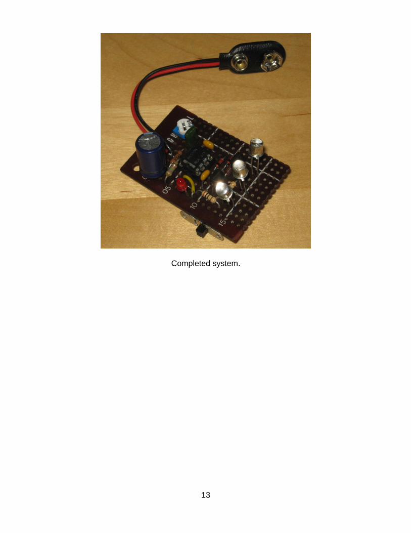
Step 4: System completion. Complete the final construction at this step. A small non-conducting box can be used to house the board. Unsnap the battery cap to turn off the unit since there is no on-off switch. Use an IR sensor to check the performance of the system. You might want to find out the effective detection range with the low/high selection of SW1. You might also want to adjust frequency with VR1 for the maximum detection range.
13
Completed system.
14
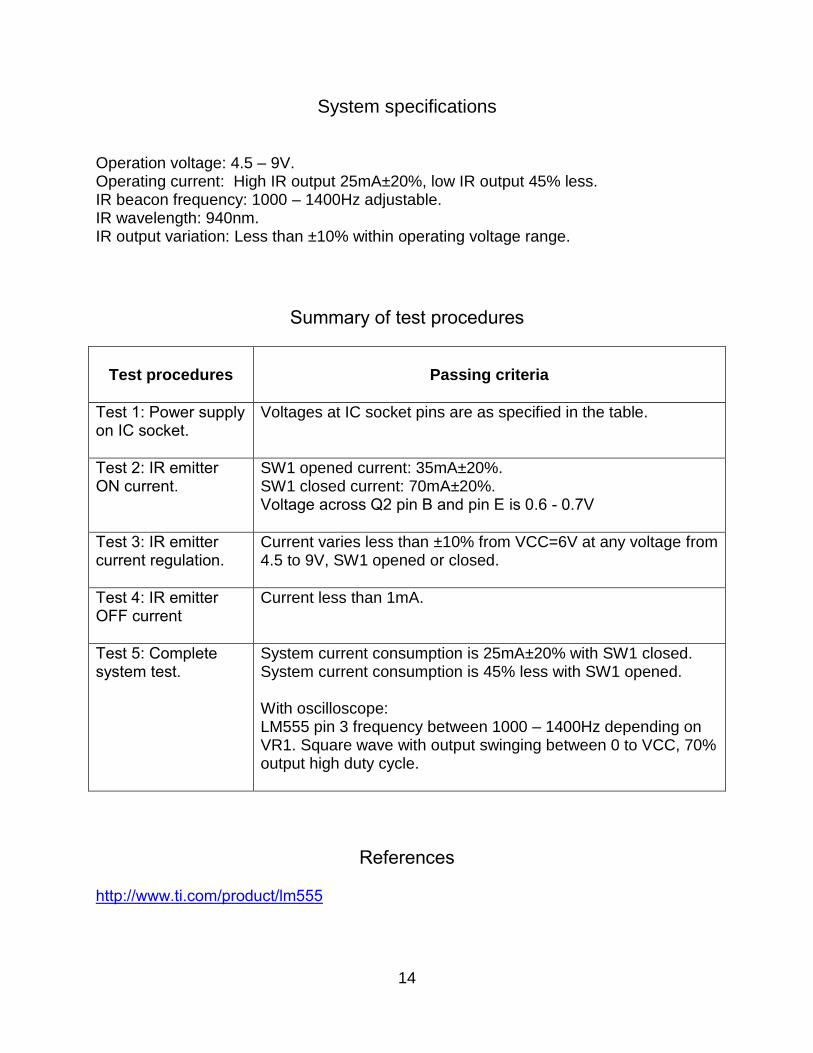
System specifications Operation voltage: 4.5 – 9V. Operating current: High IR output 25mA±20%, low IR output 45% less. IR beacon frequency: 1000 – 1400Hz adjustable. IR wavelength: 940nm. IR output variation: Less than ±10% within operating voltage range.
Summary of test procedures
Test procedures
Passing criteria
Test 1: Power supply on IC socket.
Voltages at IC socket pins are as specified in the table.
Test 2: IR emitter ON current.
SW1 opened current: 35mA±20%. SW1 closed current: 70mA±20%. Voltage across Q2 pin B and pin E is 0.6 - 0.7V
Test 3: IR emitter current regulation.
Current varies less than ±10% from VCC=6V at any voltage from 4.5 to 9V, SW1 opened or closed.
Test 4: IR emitter OFF current
Current less than 1mA.
Test 5: Complete system test.
System current consumption is 25mA±20% with SW1 closed. System current consumption is 45% less with SW1 opened. With oscilloscope: LM555 pin 3 frequency between 1000 – 1400Hz depending on VR1. Square wave with output swinging between 0 to VCC, 70% output high duty cycle.
References http://www.ti.com/product/lm555