kinetics and reaction engineering - wordpress.com · kinetics and reaction engineering ... these...
TRANSCRIPT
XKinetics and Reaction Engineering
John L. FalconerUniversity of Colorado
75 Reaction Kinetics K. H. LinFundamentals • Analysis of Kinetic Data
76 Chemical Reaction Engineering H. S. FoglerThe Algorithm • Pressure Drop in Reactors • Multiple Reactions • Heat Effects • Summary
77 The Scaleup of Chemical Reaction Systems from Laboratory to Plant J. B. CropleyGeneral Considerations in the Rational Design of Chemical Reactors • Protocol for the Rational Design ofChemical Reactors
CHEMICAL REACTORS ARE THE MOST IMPORTANT PART of a chemical plant. In mostcases, multiple reactions take place, multiple reactors are required, and catalysts are used to obtainsufficient rates and desired selectivities. Improvements in reaction rates and selectivities to desiredproducts can have significant influences on other parts of the chemical plant such as theseparations processes. Thus, design of the chemical reactor can control the economics of a planteven though the reactor is not the most expensive part. The chemical reactor also determines theamounts of waste products that form and thus the plant's effect on the environment. Becausehighly exothermic reactions are often carried out in chemical reactors on a large scale, the reactoris also the biggest safety hazard in the plant.
The first chapter of Section X is concerned with chemical kinetics and the analysis of kineticdata. The most important aspect of chemical kinetics is the rate at which a chemical reaction takesplace and the selectivity to reaction products. Also of interest is how the rate and selectivitydepend on concentrations, temperature, and other reaction conditions. Reaction rates and theproducts that form for a given set of reactants and reaction conditions cannot be predicted; suchkinetic information must be measured. These measurements are particularly sensitive totemperature because most chemical reactions exhibit an exponential dependence on temperature.They also must be made in the absence of transport effects such as diffusion and mass transfer.Moreover, many large-scale chemical processes use catalysts, and the composition andpreparation of the catalyst can have a large influence on both the rate of reaction and the productdistribution. The basic methods for analyzing laboratory kinetic data to determine rate expressionsare presented in this section, and the mechanisms by which reactions occur on a molecular scaleare also discussed.
The second chapter discusses the design and analysis of chemical reactors. Reaction engineeringinvolves determining how the type of reactor, its size, and its operating conditions affectproduction rates and distribution of products. Industrial processes almost always involve multiplereactions taking place simultaneously, and the desired product is often not the more favored
© 1998 by CRC PRESS LLC

thermodynamically. Batch, semibatch, continuous stirred tank (CSTR), and plug flow reactors arediscussed. These ideal reactor types are often used in combination and are used to model realreactors, which may deviate significantly from ideal behavior. Once kinetic data have beenobtained in the laboratory, the kinetic rate expression, thermodynamic equilibrium, and reactionstoichiometry can be used in material balances (conservation of mass) and energy balances (firstlaw of thermodynamics) to obtain equations that predict how a large-scale reactor will behave.Large-scale reactors must take account of pressure drop, nonideal flow patterns, and transportlimitations.
The last chapter describes scale-up of a reaction system from the laboratory to a large-scaleplant using laboratory data and correlations, and presents a protocol for rational design. This couldbe called scale-down since it starts from a potential type of commercial reactor, and then alaboratory system is designed to generate the necessary kinetic data. A statistically valid kineticmodel is then developed from the data, and this is used with the material and energy balances todevelop a model that simulates the reactor. This model of a reactor can then be used to develop anoptimal design, which is then validated in a pilot plant. This chapter also discusses industrialreactor types, reactor mass balances, and design of laboratory reactors. In addition to the basicideal reactors, fluidized beds, shell-and-tube packed beds, multiphase packed beds, and slurryreactors are discussed.
© 1998 by CRC PRESS LLC

75Reaction Kinetics
75.1 FundamentalsBasic Terms and Equations • Rate Constant and Elementary Reactions • Complex (or Multiple) Reactions •Uncatalyzed Heterogeneous Reactions • Homogeneous and Heterogeneous Catalytic Reactions
75.2 Analysis of Kinetic DataData Acquisition • Evaluation of Reaction Mechanism • Development of Rate Equation • Determination ofRate Constant and Arrhenius Parameters
K. H. LinOak Ridge National Laboratory
This chapter presents a brief overview of reaction kinetics primarily for engineers who are notdirectly involved in the investigation of reaction kinetics or in the design of chemical reactors. Fora comprehensive treatise on reaction kinetics, the reader should consult the references at the end ofthe chapter.
In contrast to the static and equilibrium concept of thermodynamics, reaction kinetics isconcerned with dynamics of chemical changes. Thus, reaction kinetics is the science thatinvestigates the rate of such chemical changes as influenced by various process parameters andattempts to understand the mechanism of the chemical changes. For any reaction system to changefrom an initial state to a final state, it must overcome an energy barrier. The presence of such anenergy barrier is commonly manifested in the observed relationship between the reaction rate andtemperature, which will be discussed in some detail in the section to follow.
75.1 Fundamentals
Basic Terms and EquationsOne of the key terms in reaction kinetics is the rate of reaction , rA , the general definition ofwhich is given by
rA =1
y
dNA
dt(75:1)
which expresses the rate rA as the amount of a chemical component of interest being converted orproduced per unit time per unit quantity of a reference variable y [e.g., volume of reactingmixture (V ) or of reactor (VR), mass (W ), surface area (S ), etc.]. It delineates the time
© 1998 by CRC PRESS LLC

dependence of chemical changes involving component A as a derivative. In homogeneous fluidreactions, y is normally represented by V or VR , whereas the mass (W ) or the surface area (S ) ofthe solid reactant may be taken as y in heterogeneous solid-fluid reactions. Here, NA refers to theamount of component A , and t is time. By convention, rA is negative when A is a reactant andpositive when A is a product. Molal units are commonly used as the amount of NA , but otherunits such as mass, radioactivity, pressure, and optical property are also used. When V remainsconstant (as in a liquid-phase batch reactor), Eq. (75.1) is simplified to
rA = dCA=dt (75:2)
where CA represents the concentration of component A .
Rate Constant and Elementary ReactionsIn general, the rate of reaction in terms of component i is a function of the concentration of allcomponents participating in the reaction, C ; the temperature, T ; the pressure, P ; and otherparameters, m :
ri = function (C; T; P;m) (75:3)
Thus, the rate expression for a simple irreversible reaction in terms of the reacting componentsmay assume the following form:
¡rA = k(CA)n1 (CB )
n2 ¢ ¢ ¢ (Ci)ni (75:4)
The proportionality constant, k , is the rate constant that is markedly influenced by thetemperature and may be subject to the influence of pressure, pH, kinetic isotopes, and so on, andthe presence of catalysts. The exponents n1 , n2 ,, ni are orders of reaction with respect toindividual reacting components A , B ,..., i . The overall order of reaction refers to the sum ofn1; n2; : : : ; ni, which does not have to be an integer and may be determined empirically.
The units and value of rate constant k vary with the units of C , the specific component that krefers to, and the reaction order. The effect of temperature on k was first described by Arrheniusthrough the following equation:
k = Ae¡ERT (75:5)
where A , termed the frequency factor, has the same units as k , E is activation energy, and R isthe gas law constant. E was considered by Arrhenius as the amount of energy that a reactingsystem must have in excess of the average initial energy level of reactants to enable the reaction toproceed.
A simple or elementary reaction is one in which the order of reaction is identical to themolecularity (the number of molecules actually participating in the reaction). Under thesecircumstances, the chemical stoichiometric equation represents the true reaction mechanism, and
© 1998 by CRC PRESS LLC

the rate equation may therefore be derived directly from the stoichiometric equation. Thus, for anelementary reaction n1A + n2B = n3D , the rate equation in terms of disappearance of A wouldbe ¡rA = k(CA)n1 (CB )n2 . The values of n1 and n2 in this equation are positive integers.
Complex (or Multiple) ReactionsA reaction that proceeds by a mechanism involving more than a single reaction path or step istermed a complex reaction . Unlike elementary reactions, the mechanisms of complex reactionsdiffer considerably from their stoichiometric equations. Most industrially important reactions arecomplex reactions, the mechanisms of which can often be determined by assuming that the overallreaction consists of several elementary reaction steps. The resulting overall rate expression is thencompared with the experimental data, and the procedure is repeated until a desired degree ofagreement is obtained. Each of the elementary reaction steps may proceed reversibly,concurrently, or consecutively.
A reversible reaction is one in which conversion of reactants to products is incomplete atequilibrium because of an increasing influence of the reverse reaction as the forward reactionapproaches equilibrium. For a reversible reaction of the type
A+Bkf*)krD + E
the net forward rate of reaction in terms of disappearance of A is
¡rA = kfCACB ¡ krCDCE (75:6)
which assumes both forward and reverse reactions to be elementary.A simple example of consecutive reaction is illustrated by
Ak1!B
k2!D (75:7)
Again, assuming an elementary reaction for each reaction step, the following rate equations result:
¡rA = k1CA (75:8)
rD = k2CB (75:9)
rB = k1CA ¡ k2CB (75:10)
Parallel or simultaneous reactions are those involving one or more reactants undergoingreactions of more than one scheme, as in
Ak1!B A
k2!D
© 1998 by CRC PRESS LLC

The rate equations may assume the following forms:
¡rA = k1(CA)a + k2(CA)
b (75:11)
rB = k1(CA)a (75:12)
rD = k2(CA)b (75:13)
Under a constant-volume condition, rB = dCB=dt and rD = dCD=dt. Therefore, the relative rateof formation of B and D is derived from Eqs. (75.12) and (75.13) as
dCB=dCD = (k1=k2)(CA)a¡b (75:14)
The ratio dCB=dCD is termed the point selectivity, which is the ratio of the rate of formation ofproduct B to the rate for product D . The overall (or integrated) selectivity is obtained byintegration of this ratio, and it represents the ratio of the overall amount of product B to that ofproduct D . Equation (75.14) implies that the relative rate of formation of B is proportional to CA
when a > b, whereas it is inversely proportional to CA when a < b.In a chemical process involving complex reactions that consist of several reaction steps, one or
more steps may represent major factors in governing the overall rate of reaction. Such reactionsteps are termed the rate-controlling steps. The rate-controlling reaction steps are observed inhomogeneous complex reactions and heterogeneous reactions.
Uncatalyzed Heterogeneous ReactionsHeterogeneous reactions involve more than one phase (e.g., gas-liquid, gas-solid, liquid-solid, andgas-liquid-solid) and are generally more complicated than homogeneous reactions due tointeraction between physical and chemical processes; that is, reactants in one phase have to betransported (physical process) to the other phase, containing other reactants where the reactionstake place.
In a gas-solid reaction, for example, the reaction may proceed in several steps, as follows:
1. Reactants in the gas phase diffuse to the gas-solid interface. 2. When there is a layer of solid product and/or inert material at the interface (e.g., ash), the
reactants from the gas phase would have to diffuse through this layer before they can reachthe unreacted solid core containing other reactants.
3. The chemical reaction takes place between the reactants from the gas phase and those in theunreacted solid core.
4. The reaction products diffuse within the solid phase and/or diffuse out of the solid phaseinto the bulk of gas phase.
The step that controls the overall reaction rate will be determined by the nature of the phasesand specific reactions involved and by process conditions. Thus, the overall reaction rate is subjectto the influence of parameters that affect both the physical and chemical processes, including (a)
© 1998 by CRC PRESS LLC
patterns of phase contact, (b) the reactor geometry, (c) fluid dynamic factors (e.g., velocity anddegree of turbulence), (d) interfacial surface area, (e) mass transfer factors, (f) chemical kineticsof reactions involved, and (g) process parameters (e.g., temperature and pressure). Some of theseparameters may interact with one another. For example, in a reaction involving two distinct fluidphases (e.g., gas-liquid or liquid-liquid), parameters (d) and (e) would be affected by parameter(c).
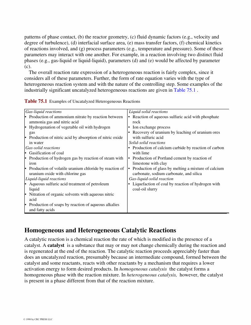
The overall reaction rate expression of a heterogeneous reaction is fairly complex, since itconsiders all of these parameters. Further, the form of rate equation varies with the type ofheterogeneous reaction system and with the nature of the controlling step. Some examples of theindustrially significant uncatalyzed heterogeneous reactions are given in Table 75.1 .
Table 75.1 Examples of Uncatalyzed Heterogeneous Reactions
Gas-liquid reactions• Production of ammonium nitrate by reaction between
ammonia gas and nitric acid• Hydrogenation of vegetable oil with hydrogen
gas• Production of nitric acid by absorption of nitric oxide
in waterGas-solid reactions• Gasification of coal• Production of hydrogen gas by reaction of steam with
iron• Production of volatile uranium chloride by reaction of
uranium oxide with chlorine gasLiquid-liquid reactions• Aqueous sulfuric acid treatment of petroleum
liquid• Nitration of organic solvents with aqueous nitric
acid• Production of soaps by reaction of aqueous alkalies
and fatty acids
Liquid-solid reactions• Reaction of aqueous sulfuric acid with phosphate
rock• Ion exchange process• Recovery of uranium by leaching of uranium ores
with sulfuric acidSolid-solid reactions• Production of calcium carbide by reaction of carbon
with lime• Production of Portland cement by reaction of
limestone with clay• Production of glass by melting a mixture of calcium
carbonate, sodium carbonate, and silicaGas-liquid-solid reaction• Liquefaction of coal by reaction of hydrogen with
coal-oil slurry
Homogeneous and Heterogeneous Catalytic ReactionsA catalytic reaction is a chemical reaction the rate of which is modified in the presence of acatalyst. A catalyst is a substance that may or may not change chemically during the reaction andis regenerated at the end of the reaction. The catalytic reaction proceeds appreciably faster thandoes an uncatalyzed reaction, presumably because an intermediate compound, formed between thecatalyst and some reactants, reacts with other reactants by a mechanism that requires a loweractivation energy to form desired products. In homogeneous catalysis the catalyst forms ahomogeneous phase with the reaction mixture. In heterogeneous catalysis, however, the catalystis present in a phase different from that of the reaction mixture.
© 1998 by CRC PRESS LLC

Homogeneous CatalysisMost homogeneous catalysis takes place in the liquid phase. Perhaps the most widely studied typeof liquid-phase catalysis is the acid-base catalysis that exerts influence on the rates of manyimportant organic reactions, including (a) esterification of alcohols, (b) hydrolysis of esters, and(c) inversion of sugars. One of the industrially important gas-phase catalytic reactions is theoxidation of SO2 to SO3 in the production of sulfuric acid, catalyzed by nitric oxide in the leadchamber.
Solid-Catalyzed ReactionThis reaction, the most common type of heterogeneous catalysis, finds extensive applications inmany important industrial processes that produce inorganic and organic chemicals. Well-knownexamples of such chemicals include HNO3 , HCl, ammonia, aniline, butadiene, ethanol,formaldehyde, methanol, organic polymers, and petrochemicals. The generally accepted,simplified mechanism of solid-catalyzed fluid (gas or liquid) phase reactions is outlined asfollows:
1. Reactants diffuse from the main body of the fluid phase to the exterior surface of catalystpellets, and subsequently into catalyst pores.
2. Reactants are adsorbed onto both the catalyst exterior and pore surfaces. 3. Products are formed from interaction of the reactants on the surfaces (catalyst exterior and
pore). 4. Products thus formed are desorbed (or released) from the surfaces; those formed on the
pore surface are released to the fluid phase within the pores and then diffuse out of pores tothe exterior surface of the catalyst pellet.
5. Products then diffuse from the exterior surfaces into the bulk of the fluid phase.
The relative importance of these steps in influencing the overall reaction rate depends upon avariety of factors, among which are thermal factors, fluid dynamic factors, properties of thecatalyst, and diffusion characteristics of the reactants and products. Besides the process stepsdescribed earlier, there are various deactivation processes that cause loss of catalytic efficiency,such as fouling and poisoning.
75.2 Analysis of Kinetic Data
Data AcquisitionBecause chemical reactions involved in most industrial processes are complex, development of thedatabase for the design of the chemical reactor facility can be quite time consuming. Accordingly,selection of experimental methods and equipment for acquisition of kinetic data is crucial indetermining the development cost as well as the accuracy and reliability of the data obtained. Inessence, the selection process is concerned with both the methods and the equipment to conductthe reactions and to monitor the progress of the reactions. The type of equipment to be used isgenerally determined by the experimental method for data acquisition. Acquisition of the kinetic
© 1998 by CRC PRESS LLC

data for homogeneous reactions is frequently carried out using a batch reactor because of itsrelatively simple design and versatility. In heterogeneous reactions a flow reactor is often utilizedfor the data acquisition. For detailed discussion on various methods and equipment for obtainingthe experimental kinetic data, the reader is referred to the references at the end of the chapter.
Evaluation of Reaction MechanismUnderstanding of the reaction mechanism is important in the selection and design of an industrialreactor for a specific reaction. Full elucidation of the mechanism, however, is not always possible,in which case derivation of the rate equation may have to resort to the empirical method (see thefollowing subsection). No simple standardized method is available for evaluation of the reactionmechanism. Nevertheless, a trial-and-error method is often used based on the experimental kineticdata acquiredincluding analysis of the reaction mixture to determine the distribution of theresidual reactants, intermediates, and final productsfollowing these steps:
1. Assume a simple elementary reaction mechanism and a corresponding stoichiometry andderive a rate equation from the assumed mechanism.
2. Evaluate the experimental data based on the proposed reaction mechanism and thecorresponding rate equation using the integral method (described in the section to follow)first since it is relatively easy to use.
3. If the experimental data do not agree with the proposed mechanism, possibly suggesting anonelementary reaction, propose a new mechanism that consists of several elementaryreaction steps with formation of intermediate compounds.
4. Develop rate equations for individual elementary reaction steps and combine the individualrate equations to represent the overall rate expression.
5. If the experimental kinetic data do not fit into the rate equation developed above, assume analternate mechanism, and repeat step 4. Continue this process until a desired degree ofagreement is reached between the experimental data and the rate expression.
6. Evaluation of the reaction mechanism may also be accomplished using the differentialmethod (see the next subsection), especially for complicated reactions. The method ofapproach is similar to that using the integral method, but it requires more accurate andextensive experimental data.
An example of a nonelementary complex reaction consisting of several elementary reaction stepsis the formation of hydrogen bromide from hydrogen and bromine:
© 1998 by CRC PRESS LLC

Br2 *) Br _ + Br _ Initiation and termination
Br _ + H2 ! HBr + H _ Propagation
H _ + Br2 ! HBr + Br _ Propagation
H _ + HBr ! Br _ + H2 Propagation
Br2 + H2 ! 2HBr Overall stoichiometric reaction
Based on the above reaction mechanism, the following rate equation has been derived:
rHBr =k1CH2C
0:5Br2
1 + k2(CHBr =CBr2 )(75:15)
Development of Rate EquationFor reactions with simple mechanism under isothermal conditions, either the integral method orthe differential method (discussed in a later section) may be used in the derivation of rateequations. It is assumed that the data representing the extent of an isothermal reaction areavailable in terms of the time variation of a selected component A .
Integral MethodAn elementary reaction mechanism is first assumed; for example, a second-order isothermalhomogeneous reaction under constant-volume conditions, A+B ! C +D, results in the rateequation of the form
¡rA =dCA
dt= kCACB (75:16)
and the integrated rate equation becomes
kt =1
CB0 ¡ CA0
lnCA0 (CA + CB0 ¡ CA0 )
CACB0
(75:17)
where CA0 and CB0 represent the initial concentrations of reactants A and B , respectively. Oneway to confirm the proposed reaction mechanism is to compute values of k at various values ofCA and t . If the values of k remain nearly constant, the proposed mechanism is accepted.Otherwise, another mechanism is assumed and the process is repeated until a desired degree ofagreement is reached.
When the volume of the reaction mixture varies with the extent of reaction, the rate equationbecomes more complicated. In this case, if it is assumed that the volume varies linearly with the
© 1998 by CRC PRESS LLC
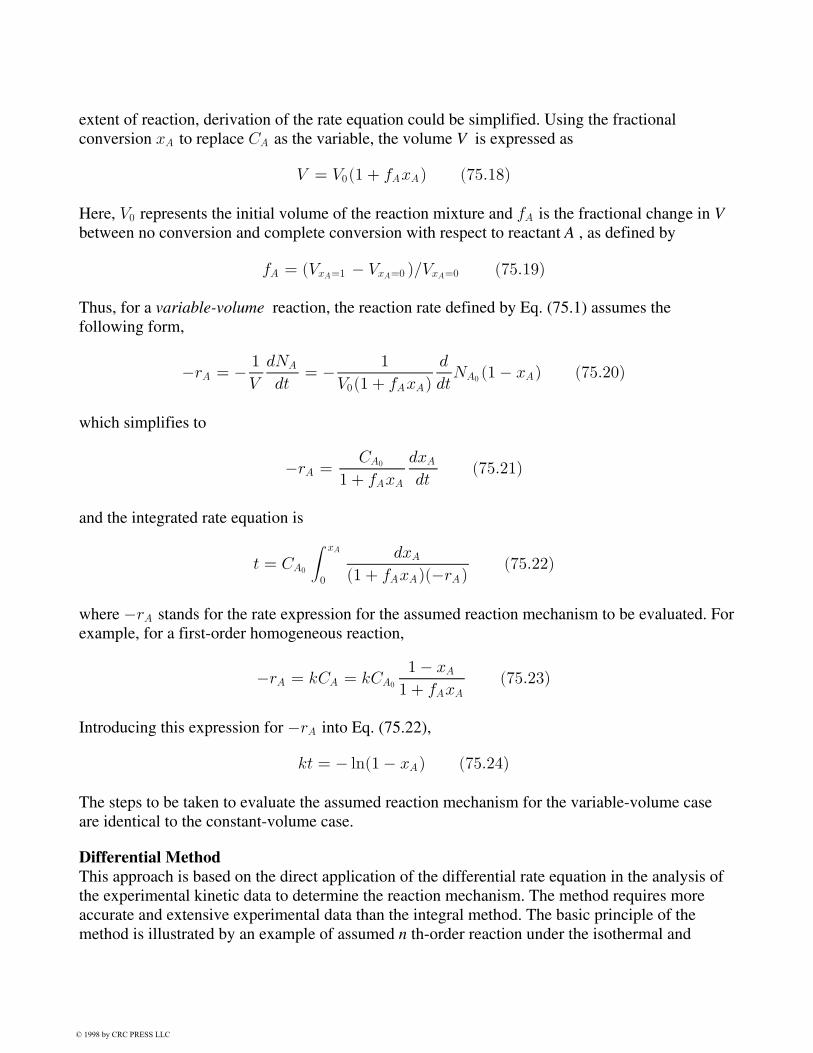
extent of reaction, derivation of the rate equation could be simplified. Using the fractionalconversion xA to replace CA as the variable, the volume V is expressed as
V = V0(1 + fAxA) (75:18)
Here, V0 represents the initial volume of the reaction mixture and fA is the fractional change in Vbetween no conversion and complete conversion with respect to reactant A , as defined by
fA = (VxA=1 ¡ VxA=0 )=VxA=0 (75:19)
Thus, for a variable-volume reaction, the reaction rate defined by Eq. (75.1) assumes thefollowing form,
¡rA = ¡ 1
V
dNA
dt= ¡ 1
V0(1 + fAxA)
d
dtNA0 (1¡ xA) (75:20)
which simplifies to
¡rA =CA0
1 + fAxA
dxA
dt(75:21)
and the integrated rate equation is
t = CA0
Z xA
0
dxA
(1 + fAxA)(¡rA)(75:22)
where ¡rA stands for the rate expression for the assumed reaction mechanism to be evaluated. Forexample, for a first-order homogeneous reaction,
¡rA = kCA = kCA0
1¡ xA
1 + fAxA
(75:23)
Introducing this expression for ¡rA into Eq. (75.22),
kt = ¡ ln(1¡ xA) (75:24)
The steps to be taken to evaluate the assumed reaction mechanism for the variable-volume caseare identical to the constant-volume case.
Differential MethodThis approach is based on the direct application of the differential rate equation in the analysis ofthe experimental kinetic data to determine the reaction mechanism. The method requires moreaccurate and extensive experimental data than the integral method. The basic principle of themethod is illustrated by an example of assumed n th-order reaction under the isothermal and
© 1998 by CRC PRESS LLC

constant-volume condition:
aA+ bB = dD + eE
With initially equimolal concentrations of A and B (i.e., CA = CB ), the rate equation may takethe following form,
¡rA = kCaAC
bB = kCa+b
A = kCnA (75:25)
which is rearranged into
log(¡rA) = log(¡dCA=dt) = log k + n logCA (75:26)
The assumption of the n th-order reaction mechanism is confirmed if a log-log plot of (dCA=dt)versus CA results in a straight line.
The next step is to evaluate the values of the rate constant k and the overall order of reaction nfrom the plot. With the known values of k and n , the reaction orders with respect to A and B canbe determined by the method that follows. Rearranging Eq. (75.25),
¡rA = kCaAC
n¡aB = kCn
B (CA=CB )a (75:27)
On further rearrangement,
log
µ¡ rAkCn
B
¶= a log(CA=CB ) (75:28)
A log-log plot of Eq. (75.28) yields the reaction order a with respect to A , whereas the reactionorder b is obtained as the difference between n and a .
Empirical MethodThis method, which finds uses when the reaction mechanism appears to be complex, is oftenbased on a mathematical approach using the curve-fitting procedure. The method involves atrial-and-error technique to fit the experimental data to a relatively simple form of the empiricalequation, including (a) linear form, y = a+ bx, (b) semilogarithmic form, y = aebx , (c)logarithmic form, y = c+ axn , and so forth. The initial step usually consists of plotting theexperimental data on graph papers of different coordinates that may produce a straight line. Uponselection of a proper form of the empirical equation, the constants in the empirical equation aredetermined either by the graphic means or by the analytical technique using the method ofaverages or the method of least squares. Computer software is available for performing thecurve-fitting procedure.
© 1998 by CRC PRESS LLC

The rate constant k can be obtained by using either a differential form [e.g., Eq. (75.16)] or anintegrated form [e.g., Eq. (75.17)] of the rate equation. It is an average of values calculated atvarious experimental kinetic data points (i.e., reactant concentrations at various reaction times).
Arrhenius parameters consist of the activation energy E and the frequency factor A . The valueof E may be calculated from the rate constants at two distinct but adjacent temperatures, T1 andT2 , as follows:
k1 = Ae¡E=RT1 ; k2 = Ae¡E=RT2
Combining the above two equations,
E = Rln(k2=k1)
1=T1 ¡ 1=T2
(75:29)
The value of A is calculated from one of the Arrhenius equations shown above.
Defining Terms
Activation energy: A parameter associated with the Arrhenius equation and considered byArrhenius as the energy in excess of the average energy level of reactants required to enablethe reaction to proceed.
Catalyst: A substance that accelerates the reaction, presumably by making available a reactionpath that requires a lower activation energy. The catalyst may or may not change chemicallyduring the reaction and is regenerated at the end of the reaction.
Rate constant: A proportionality constant in the rate equation. The rate constant is markedlyinfluenced by temperature and, to lesser degree, by pressure and the presence of catalysts.The units and value of the rate constant depend on the specific chemical component to whichit refers, the units for concentration (or other quantity) of the component, and the reactionorder.
Rate-controlling step: The slow steps that tend to control the overall rate of reaction. In acomplex reaction consisting of several chemical reaction steps (and physical process steps inheterogeneous reaction), the reaction rate (and physical process rate) of one or more stepsmay be much slower than other steps.
Rate equation: A functional expression describing the relationship between the rate of reactionand the amounts (e.g., concentrations) of selected chemical components participating in thereaction at any time under isothermal condition.
Rate of reaction: The amount of a chemical component of concern being converted or producedper unit time per unit quantity of a reference variable. Examples of the reference variableinclude the volume of reacting mixture, the reactor volume, the mass of solid (solid-fluidreaction), and the surface area of solid.
Determination of Rate Constant and Arrhenius Parameters
© 1998 by CRC PRESS LLC
Carberry, J. J. 1976. Chemical and Catalytic Reaction Engineering. McGraw-Hill, New York.Connors, K. A. 1990. Chemical KineticsThe Study of Reaction Rates in Solution. VCH, New
York.Katakis, D. and Gordon, G. 1987. Mechanisms of Inorganic Reactions. John Wiley & Sons, New
York.Lin, K. H. 1984. Reaction kinetics, reactor design (section 4). In Perry's Chemical Engineers' Handb
−4.52. McGraw-Hill, New York.Moore, J. W. and Pearson, R. G. 1981. Kinetics and Mechanism, 3rd ed. John Wiley & Sons,
New York.
Further Information
The following professional journals provide good sources for examples of basic and appliedreaction kinetic studies on specific reactions of industrial importance:
AIChE Journal. Published monthly by the American Institute of Chemical Engineers, New York,NY.
Chem. Eng. Sci. Published semimonthly by Elsevier Science, Oxford, U.K.Ind. Eng. Chem. Res. Published monthly by the American Chemical Society, Washington, D.C.J. Am. Chem. Soc. Published biweekly by the American Chemical Society, Washington, D.C.J. Catal. Published monthly by Academic Press, Orlando, FL.J. Chem. Soc.Faraday Trans. Published semimonthly by The Royal Society of Chemistry,
Cambridge, U.K.Trans. Inst. Chem. Eng. (London)Chem. Eng. and Design. Published bimonthly by the
Institute of Chemical Engineers, Basinstoke, U.K.
References
© 1998 by CRC PRESS LLC

76Chemical Reaction Engineering
76.1 The AlgorithmMole Balances • Rate Laws • Stoichiometry
76.2 Pressure Drop in Reactors76.3 Multiple Reactions76.4 Heat Effects76.5 Summary
H. Scott FoglerUniversity of Michigan
Chemical reaction engineering (CRE) sets chemical engineers apart from other engineers.Students and professionals can easily learn the elements of CRE because it has a very logicalstructure. The six basic pillars that hold up what you might call the "temple" of chemical reactionengineering are shown in Fig. 76.1 .
Figure 76.1 Pillars of the temple of chemical reaction engineering. (Source: Fogler, H. S. 1992. TheElements of Chemical Reaction Engineering, 2nd ed. Prentice Hall, Englewood Cliffs, NJ.)
© 1998 by CRC PRESS LLC
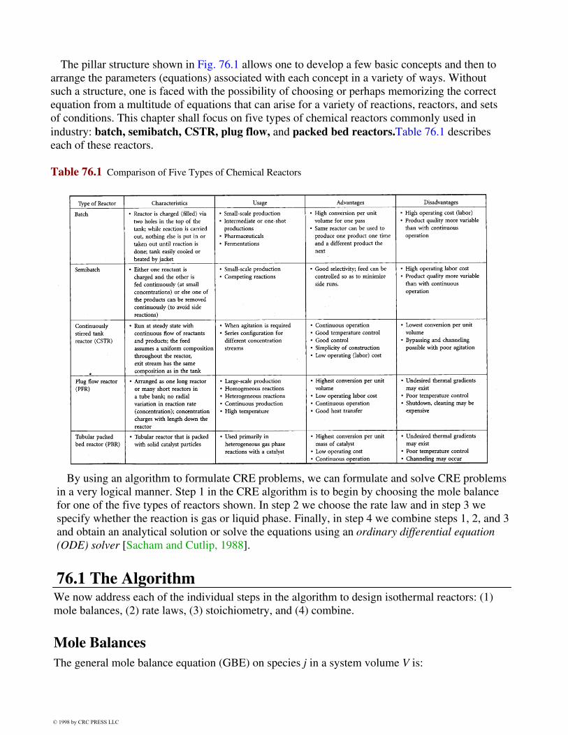
The pillar structure shown in Fig. 76.1 allows one to develop a few basic concepts and then toarrange the parameters (equations) associated with each concept in a variety of ways. Withoutsuch a structure, one is faced with the possibility of choosing or perhaps memorizing the correctequation from a multitude of equations that can arise for a variety of reactions, reactors, and setsof conditions. This chapter shall focus on five types of chemical reactors commonly used inindustry: batch, semibatch, CSTR, plug flow, and packed bed reactors.Table 76.1 describeseach of these reactors.
Table 76.1 Comparison of Five Types of Chemical Reactors
By using an algorithm to formulate CRE problems, we can formulate and solve CRE problemsin a very logical manner. Step 1 in the CRE algorithm is to begin by choosing the mole balancefor one of the five types of reactors shown. In step 2 we choose the rate law and in step 3 wespecify whether the reaction is gas or liquid phase. Finally, in step 4 we combine steps 1, 2, and 3and obtain an analytical solution or solve the equations using an ordinary differential equation(ODE) solver [Sacham and Cutlip, 1988].
76.1 The AlgorithmWe now address each of the individual steps in the algorithm to design isothermal reactors: (1)mole balances, (2) rate laws, (3) stoichiometry, and (4) combine.
Mole BalancesThe general mole balance equation (GBE) on species j in a system volume V is:
© 1998 by CRC PRESS LLC

2
4Molar °ow
rate
IN
3
5 ¡
2
4Molar °ow
rate
OUT
3
5 +
2
4Molar rate
of
GENERATION
3
5 =
2
4Molar rate
of
ACCUMULATION
3
5
Fj0 ¡ Fj +R v
0rjdV =
dNj
dt(76:1)
We now make use of the definition of conversion, X, with respect to the limiting reactant, whichwe shall call species A,
Batch Flow
X = (NA0 ¡NA)=NA0 X = (FA0 ¡ FA)=FA0
and apply the GME to each of the following reactors: batch, continuous stirred tank reactors(CSTR), plug flow reactor (PFR), and packed bed reactor (PBR). The CSTR, PFR, and PBR areall operated at steady state (i.e., dNj=dt = 0 ) and it is assumed that the PBR and PFR are in plugflow (no radial gradients or dispersion) and that the contents of the CSTR are well mixed. There isno in-flow or out-flow (Fj0 = Fj = 0 ) in the batch reactor. When these conditions and thedefinition of conversion are applied to the general mole balance, the design equations (76.2 to76.8) in Table 76.2 result.
Table 76.2 Design Equations
Reactor Differential Algebraic IntegralBatch
NA0dX
dt= ¡rAV (76:2) t = Na0
Z x
0
dX
¡rAV(76:3)
CSTR V =FA0X
¡rA(76:4)
PFRFA0
dX
dV= ¡rA(76:5) V = FA0
Z x
0
dX
¡rA(76:6)
PBRFA0
dX
dW= ¡r0A(76:7) W = FA0
Z x
0
dX
¡r0A(76:8)
In order to evaluate the design equations given in Table 76.2 we must determine the form of therate of formation, rA . We do this with the aid of a rate law.
Rate LawsThe power law model is one of the most commonly used forms for the rate law. It expresses therate of reaction as a function of the concentrations of the species involved in thereaction.
For the irreversible reaction in which A is the limiting reactant,
© 1998 by CRC PRESS LLC
A +b
aB ! c
aC + d D (76:9)
the rate law is
¡rA = kC®AC
¯B (76:10)
We say the reaction is ® order in A, ¯ order in B, and overall order = ® + ¯ . For example, if thereaction A + B ! C +D is said to be second order in A and first order in B and overall thirdorder, then the rate law is
¡rA = kC2ACB (76:11)
The temperature dependence of specific reaction rate, k, is given by the Arrheniusequation,
k = Ae¡E=RT (76:12)
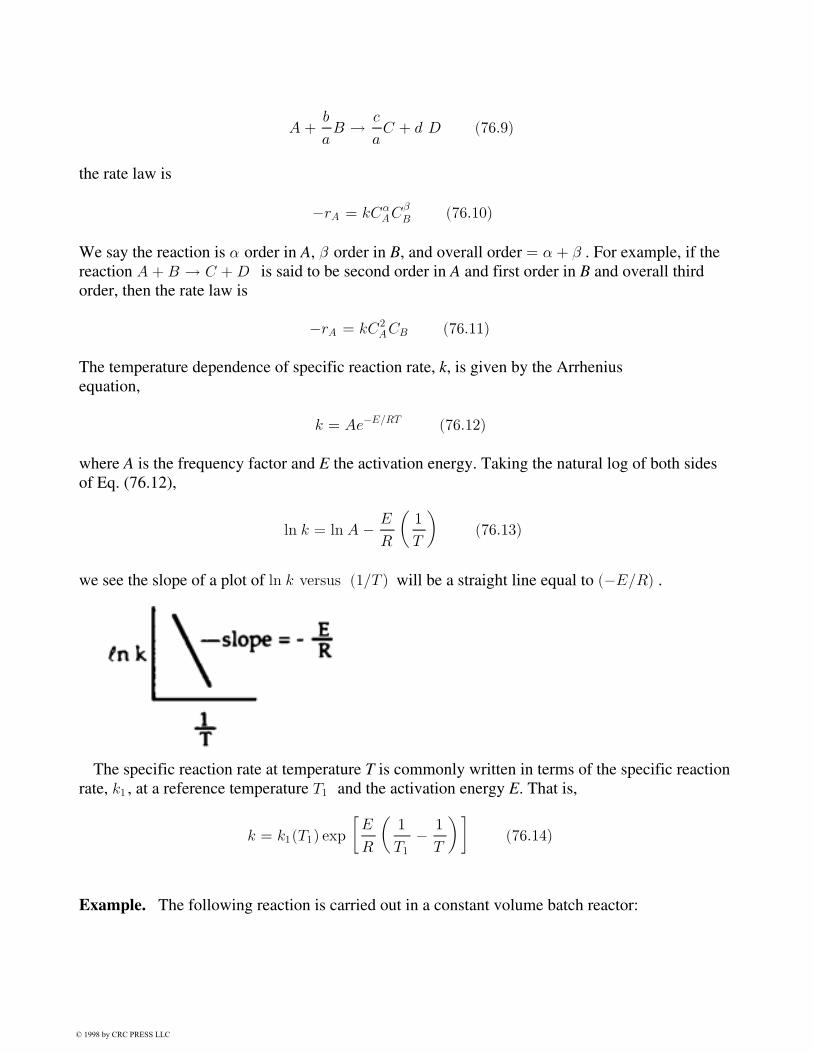
where A is the frequency factor and E the activation energy. Taking the natural log of both sidesof Eq. (76.12),
ln k = ln A ¡ E
R
µ1
T
¶(76:13)
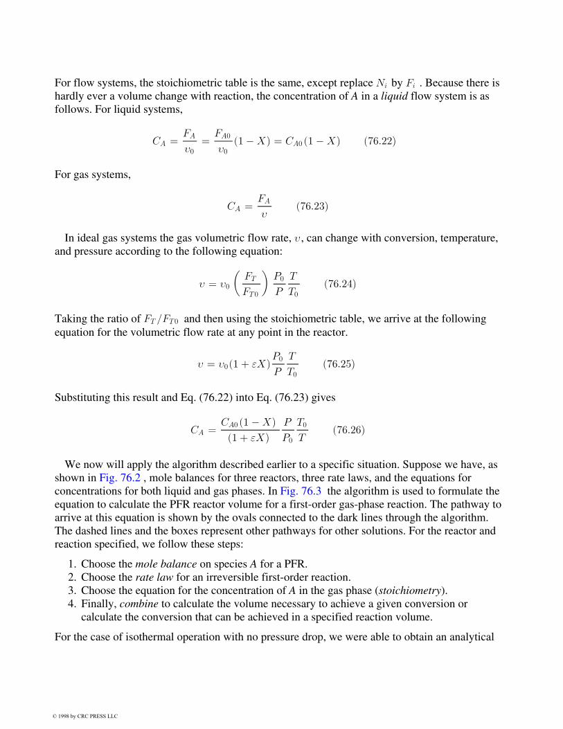
we see the slope of a plot of ln k versus (1=T ) will be a straight line equal to (¡E=R) .
The specific reaction rate at temperature T is commonly written in terms of the specific reactionrate, k1 , at a reference temperature T1 and the activation energy E. That is,
k = k1(T1) exp
·E
R
µ1
T1
¡ 1
T
¶¸(76:14)
Example. The following reaction is carried out in a constant volume batch reactor:
© 1998 by CRC PRESS LLC

A ! Products
Determine the appropriate linearized concentration-time plots for zero-, first-, and second-orderreactions.Solution. Use the algorithm to determine the concentration of A as a function of time.
Mole balance:dNA
dt= rAV (76:15)
Rate law: ¡ rA = kC®A (76:16)
Stoichiometry: V = V0 CA = NA=V0 (76:17)
Combine: ¡ dCA
dt= kC®
A (76:18)
Solving Eq. (76.18) for a first-, second-, and third-order rate law, we can arrive at the followinglinearized concentration-time plots.
For reversible reactions at equilibrium the rate law must reduce to a thermodynamically consistentequation for the equilibrium constant.
StoichiometryNow that we have the rate law as a function of concentration (i.e., ¡rA = kC®
AC¯B ), we need to
express the concentrations of the reacting species as functions of conversion in order to evaluateany one of the reactor design equations.
ConcentrationWe start by defining concentration for a flow system and a batch system. For a flowsystem,
© 1998 by CRC PRESS LLC
Ci =Fi
À(76:19)
where À is the volumetric flow rate. For a batch system,
Ci =Ni
V(76:20)
The next step is to express Ni and Fi as a function of conversion using a stoichiometrictable.
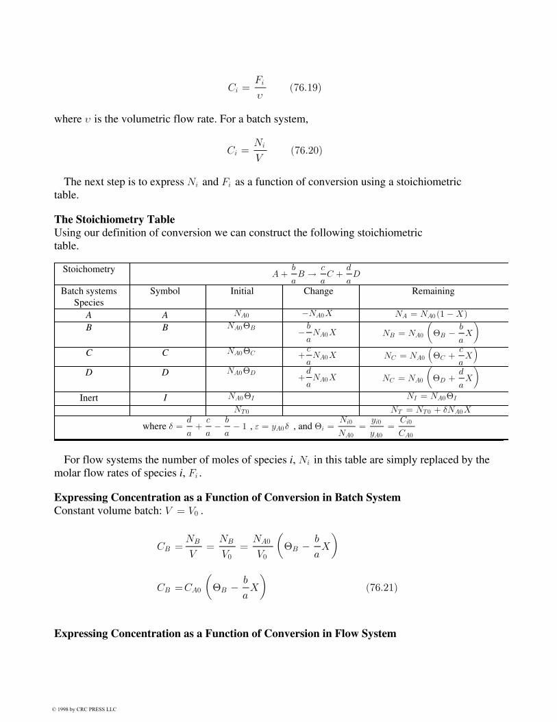
The Stoichiometry TableUsing our definition of conversion we can construct the following stoichiometrictable.
StoichometryA +
b
aB ! c
aC +
d
aD
Batch systemsSpecies
Symbol Initial Change Remaining
A A NA0 ¡NA0X NA = NA0 (1 ¡ X)
B B NA0£B ¡ b
aNA0X NB = NA0
µ£B ¡ b
aX
C C NA0£C +c
aNA0X NC = NA0
³£C +
c
aX´
D D NA0£D+d
aNA0X NC = NA0
µ£D +
d
aX
Inert I NA0£I NI = NA0£I
NT0 NT = NT0 + ±NA0X
where ± =d
a+
c
a¡ b
a¡ 1 , " = yA0± , and £i =
Ni0
NA0
=yi0
yA0=
Ci0
CA0
For flow systems the number of moles of species i, Ni in this table are simply replaced by themolar flow rates of species i, Fi .
Expressing Concentration as a Function of Conversion in Batch SystemConstant volume batch: V = V0 .
CB =NB
V=
NB
V0
=NA0
V0
µ£B ¡ b
aX
CB =CA0
µ£B ¡ b
aX
¶(76:21)
Expressing Concentration as a Function of Conversion in Flow System
© 1998 by CRC PRESS LLC
For flow systems, the stoichiometric table is the same, except replace Ni by Fi . Because there ishardly ever a volume change with reaction, the concentration of A in a liquid flow system is asfollows. For liquid systems,
CA =FA
À0=
FA0
À0(1 ¡X) = CA0 (1 ¡X) (76:22)
For gas systems,
CA =FA
À(76:23)
In ideal gas systems the gas volumetric flow rate, À, can change with conversion, temperature,and pressure according to the following equation:
À = À0
µFT
FT0
¶P0
P
T
T0
(76:24)
Taking the ratio of FT =FT0 and then using the stoichiometric table, we arrive at the followingequation for the volumetric flow rate at any point in the reactor.
À = À0(1 + "X)P0
P
T
T0
(76:25)
Substituting this result and Eq. (76.22) into Eq. (76.23) gives
CA =CA0 (1 ¡X)
(1 + "X)
P
P0
T0
T(76:26)
We now will apply the algorithm described earlier to a specific situation. Suppose we have, asshown in Fig. 76.2 , mole balances for three reactors, three rate laws, and the equations forconcentrations for both liquid and gas phases. In Fig. 76.3 the algorithm is used to formulate theequation to calculate the PFR reactor volume for a first-order gas-phase reaction. The pathway toarrive at this equation is shown by the ovals connected to the dark lines through the algorithm.The dashed lines and the boxes represent other pathways for other solutions. For the reactor andreaction specified, we follow these steps:
1. Choose the mole balance on species A for a PFR.2. Choose the rate law for an irreversible first-order reaction.3. Choose the equation for the concentration of A in the gas phase (stoichiometry).4. Finally, combine to calculate the volume necessary to achieve a given conversion or
calculate the conversion that can be achieved in a specified reaction volume.
For the case of isothermal operation with no pressure drop, we were able to obtain an analytical
© 1998 by CRC PRESS LLC
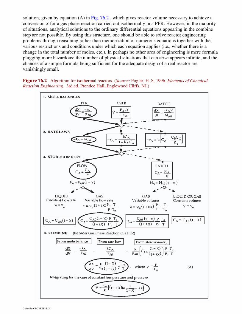
solution, given by equation (A) in Fig. 76.2 , which gives reactor volume necessary to achieve aconversion X for a gas phase reaction carried out isothermally in a PFR. However, in the majorityof situations, analytical solutions to the ordinary differential equations appearing in the combinestep are not possible. By using this structure, one should be able to solve reactor engineeringproblems through reasoning rather than memorization of numerous equations together with thevarious restrictions and conditions under which each equation applies (i.e., whether there is achange in the total number of moles, etc.). In perhaps no other area of engineering is mere formulaplugging more hazardous; the number of physical situations that can arise appears infinite, and thechances of a simple formula being sufficient for the adequate design of a real reactor arevanishingly small.
Figure 76.2 Algorithm for isothermal reactors. (Source: Fogler, H. S. 1996. Elements of ChemicalReaction Engineering. 3rd ed. Prentice Hall, Englewood Cliffs, NJ.)
© 1998 by CRC PRESS LLC
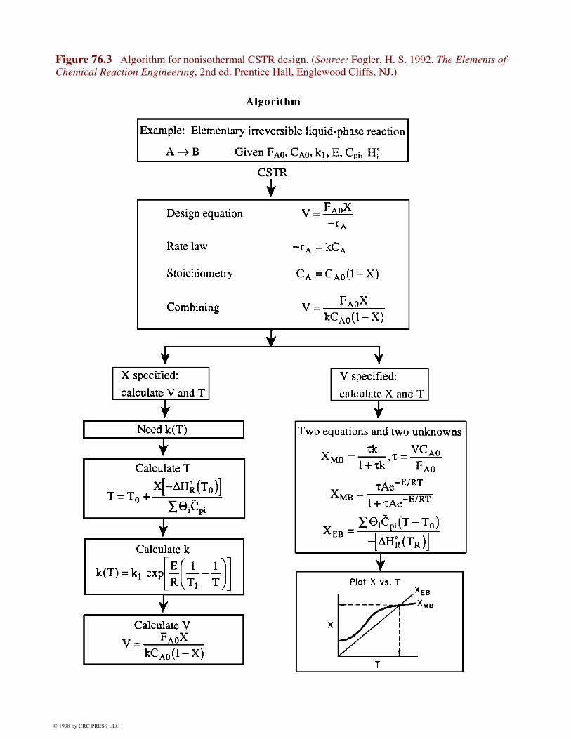
Figure 76.3 Algorithm for nonisothermal CSTR design. (Source: Fogler, H. S. 1992. The Elements ofChemical Reaction Engineering, 2nd ed. Prentice Hall, Englewood Cliffs, NJ.)
© 1998 by CRC PRESS LLC
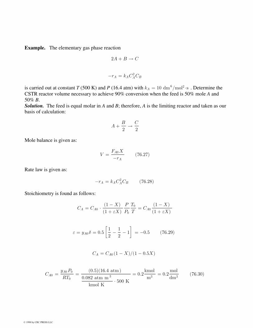
Example. The elementary gas phase reaction
2A + B ! C
¡rA = kAC2ACB
is carried out at constant T (500 K) and P (16.4 atm) with kA = 10 dm6=mol2 ¢s . Determine theCSTR reactor volume necessary to achieve 90% conversion when the feed is 50% mole A and50% B.Solution. The feed is equal molar in A and B; therefore, A is the limiting reactor and taken as ourbasis of calculation:
A +B
2! C
2
Mole balance is given as:
V =FA0X
¡rA(76:27)
Rate law is given as:
¡rA = kAC2ACB (76:28)
Stoichiometry is found as follows:
CA = CA0 ¢ (1 ¡X)
(1 + "X)
P
P0
T0
T= CA0
(1 ¡X)
(1 + "X)
" = yA0 ± = 0:5
·1
2¡ 1
2¡ 1
¸= ¡0:5 (76:29)
CA = CA0 (1 ¡X)=(1 ¡ 0:5X)
CA0 =yA0P0
RT0
=(0:5)(16:4 atm)
0:082 atm m 3
kmol K¢ 500 K
= 0:2kmol
m3= 0:2
mol
dm3(76:30)
© 1998 by CRC PRESS LLC

CB = CA0
£B ¡ 1
2X
(1 + "X)= CA0
(1 ¡ 0:5X)
(1 ¡ 0:5X)= CA0 (76:31)
For the combine step,
¡rA = kAC2ACB = kAC
3A0
(1 ¡X)2
(1 ¡ 0:5X)2
= 0:08mol
dm3 ¢ s(1 ¡X)2
(1 ¡ 0:5X)2(76:32)
For a CSTR,
V =FA0X
¡rA=
(5 mol/s )(0:9)[1 ¡ 0:5(0:9)]2
(0:08)mol
dm3 ¢ s (1 ¡ 0:9)2
= 1701 dm3 (76:33)
76.2 Pressure Drop in ReactorsIf pressure drop is not accounted for in gas phase reactions, significant underdesign of the reactorsize can result. This variation is handled in the stoichiometry step, in which concentration isexpressed as a function of conversion, temperature, and total pressure. The change in totalpressure is given by the Ergun equation [Fogler, 1992]:
dP
dL= ¡G(1 ¡ Á)
½gCDpÁ3
·150(1 ¡ Á)¹
Dp
+ 1:75G
¸(76:34)
For isothermal operation the density is (assuming ideal gas)
½ =½0
(1 + "X)
P
P0
(76:35)
The catalyst weight, W, and length down the reactor, L, are related by the equation
W = LAc(1 ¡ ©)½cat
Substituting back in the Ergun equation,
© 1998 by CRC PRESS LLC

dP
dW= ¡®P
2
(1 + "X)
1
P0
µP
P0
¶ (76:36)
where
®p =
G(1 ¡ ©)
½0gcDp©3
·150(1 ¡ ©)¹
Dp
+ 1:75G
¸
Ac(1 ¡ ©)½catP0
We now need to solve this differential equation to obtain the pressure as a function of theweight of catalyst the gas has passed over. We can obtain an analytical solution of " = 0 .Otherwise, we must solve the equation numerically and simultaneously with the mole balance. Foran analytical solution,
d(P=P0)2
dW= ¡®p(1 + "X) (76:37)
For POLYMATH solution, letting y = P=P0 ,
dy
dW= ¡®p(1 + "X)
2y(76:38)
Example. To understand the effect pressure drop has on gas phase reaction in a packed bed, weanalyze the reaction A ! B carried out in a packed bed reactor (PBR). Mole balance (PBR) is
FA0
dX
dW= ¡r0A
Wherever pressure drop occurs in a PBR we must use the differential form of the mole balance toseparate variables. Pressure drop only affects CA , CB , and so on, as well as ¡r0A .
Rate law is second order in A and irreversible, according to the formula ¡r0A = kC2A .
Stoichiometry is given by
CA = CA0
(1 ¡X)
(1 + "X)
P
P0
T0
T
For " = 0 and isothermal operation,
© 1998 by CRC PRESS LLC

P
P0
= (1 ¡ ®pW )1=2
CA = CA0 (1 ¡X)P
P0
= CA0 (1 ¡X) (1 ¡ ®pW )1=2
Combining,
FA0
dX
dW= ¡r0A = kC2
A0 (1 ¡X)2 (1 ¡ ®pW )
By integrating with limits W = 0 , X = 0 we obtain the desired relationship between conversionand catalyst weight.
X
1 ¡X=
kC2A0
FA0
·W ¡ ®pW
2
2
¸
76.3 Multiple ReactionsThere are three basic types of multiple reactions: series, parallel, and independent. In parallelreactions (also called competing reactions) the reactant is consumed by two different reactions toform different products:
In series reactions, also called consecutive reactions, the reactant forms an intermediate product,which reacts further to form another product:
Ak1¡! B
k2¡! C
Multiple reactions involve a combination of both series and parallel reactions, suchas
A + B ¡! C +D
A + C ¡! E
Independent reactions are of the type
© 1998 by CRC PRESS LLC
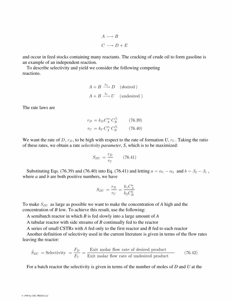
A ¡! B
C ¡! D + E
and occur in feed stocks containing many reactants. The cracking of crude oil to form gasoline isan example of an independent reaction.
To describe selectivity and yield we consider the following competingreactions.
A + BkD¡! D (desired )
A + BkU¡! U (undesired )
The rate laws are
rD = kDC®1
A C¯1
B (76:39)
rU = kU C®1
A C¯2
B (76:40)
We want the rate of D , rD , to be high with respect to the rate of formation U, rU . Taking the ratioof these rates, we obtain a rate selectivity parameter, S, which is to be maximized:
SDU =rD
rU(76:41)
Substituting Eqs. (76.39) and (76.40) into Eq. (76.41) and letting a = ®1 ¡ ®2 and b = ¯2 ¡ ¯1 ,where a and b are both positive numbers, we have
SDU =rD
rU=
k1CaA
k2CbB
To make SDU as large as possible we want to make the concentration of A high and theconcentration of B low. To achieve this result, use the following:
A semibatch reactor in which B is fed slowly into a large amount of AA tubular reactor with side streams of B continually fed to the reactorA series of small CSTRs with A fed only to the first reactor and B fed to each reactorAnother definition of selectivity used in the current literature is given in terms of the flow rates
leaving the reactor:
~SDU = Selectivity =FD
FU
=Exit molar °ow rate of desired product
Exit molar °ow rate of undesired product(76:42)
For a batch reactor the selectivity is given in terms of the number of moles of D and U at the
© 1998 by CRC PRESS LLC

end of the reaction time:
~SDU =ND
NU
(76:43)
One also finds that the reaction yield, like the selectivity, has two definitions: one based on theratio of reaction rates and one based on the ratio of molar flow rates. In the first case the yield at apoint can be defined as the ratio of the reaction rate of a given product to the reaction rate of thekey reactant A[Carbery, 1967]:
YD =rD
¡rA(76:44)
In the case of reaction yield based on molar flow rates, the yield is defined as the ratio of molesof product formed at the end of the reaction to the number of moles of the key reactant, A, thathave been consumed. For a batch system,
~YD =ND
NA0 ¡NA
(76:45)
For a flow system,
~YD =FD
FA0 ¡ FA
(76:46)
Because of the various definitions for selectivity and yield, when reading literature dealing withmultiple reactions, check carefully to ascertain the definition intended by theauthor.
76.4 Heat EffectsFor nonisothermal reaction in CRE we must choose which form of the energy balance to use (e.g.,PFR, CSTR) and which terms to eliminate (e.g., Q = 0 for adiabatic operation). The structureintroduced to study these reactors builds on the isothermal algorithm by introducing the Arrheniusequation, k = Ae¡E=RT in the rate law step, which results in one equation with two unknowns, Xand T, when we finish with the combine step. For example, using again the PFR mole balance andconditions in Fig. 76.2[Eq. (A)], we have, for constant pressure,
dX
dV=
k(1 ¡X)
À0(1 + "X)
T0
T(76:47)
dXdV
=Ae¡E=RT (1¡X)
À0 (1+"X)
¡T0
T
¢(76:48)
© 1998 by CRC PRESS LLC
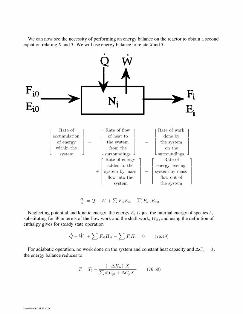
We can now see the necessity of performing an energy balance on the reactor to obtain a secondequation relating X and T. We will use energy balance to relate Xand T.
26664
Rate of
accumulation
of energy
within the
system
37775 =
26664
Rate of °ow
of heat to
the system
from the
surroundings
37775 ¡
26664
Rate of work
done by
the system
on the
surroundings
37775
+
26664
Rate of energy
added to the
system by mass
°ow into the
system
37775 ¡
26664
Rate of
energy leaving
system by mass
°ow out of
the system
37775
dEdt
= _Q ¡ _W +P
FinEin ¡P
FoutEout
Neglecting potential and kinetic energy, the energy Ei is just the internal energy of species i ,substituting for W in terms of the flow work and the shaft work, WS , and using the definition ofenthalpy gives for steady state operation
_Q ¡ _Ws +X
Fi0Hi0 ¡X
FiHi = 0 (76:49)
For adiabatic operation, no work done on the system and constant heat capacity and ¢Cp = 0 ,the energy balance reduces to
T = T0 +(¡¢HR) XPµiCpi +¢CpX
(76:50)
© 1998 by CRC PRESS LLC
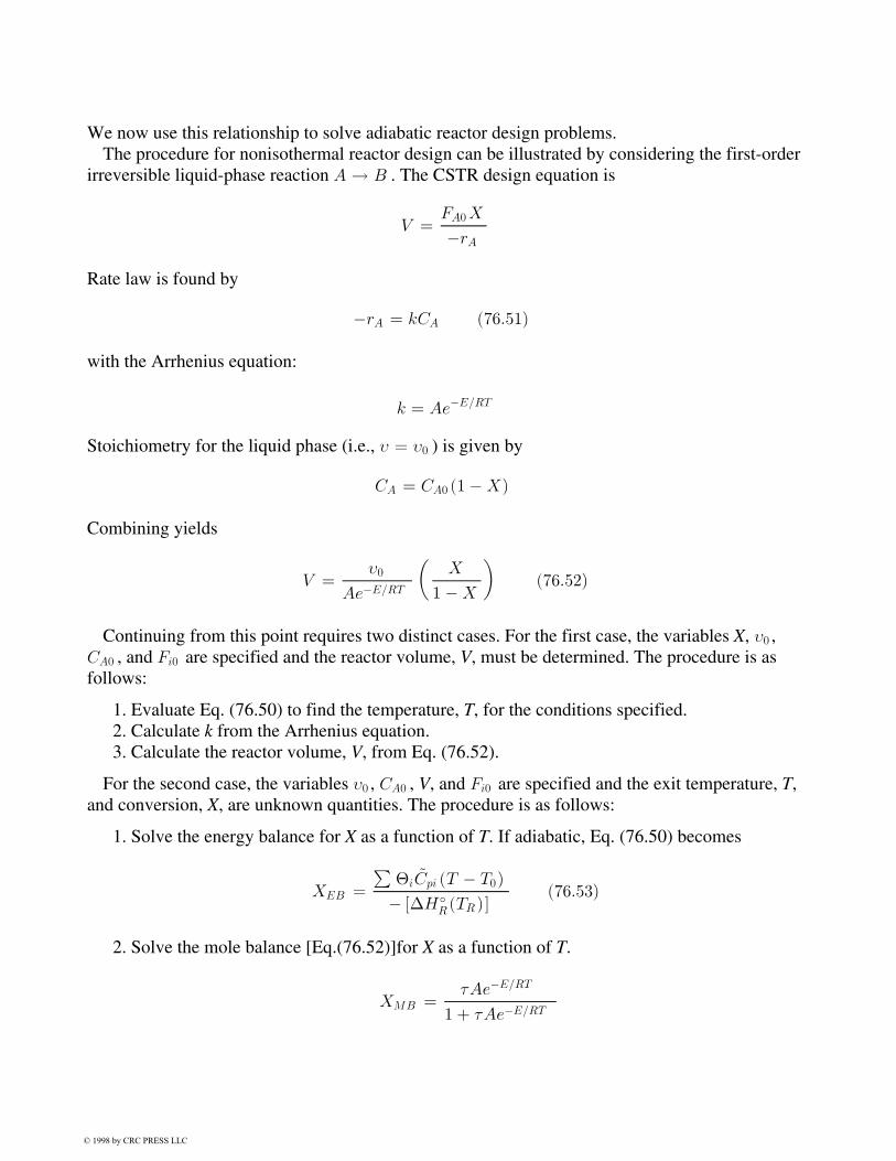
We now use this relationship to solve adiabatic reactor design problems.The procedure for nonisothermal reactor design can be illustrated by considering the first-order
irreversible liquid-phase reaction A ! B . The CSTR design equation is
V =FA0X
¡rA
Rate law is found by
¡rA = kCA (76:51)
with the Arrhenius equation:
k = Ae¡E=RT
Stoichiometry for the liquid phase (i.e., À = À0 ) is given by
CA = CA0 (1 ¡X)
Combining yields
V =À0
Ae¡E=RT
µX
1 ¡X
¶(76:52)
Continuing from this point requires two distinct cases. For the first case, the variables X, À0 ,CA0 , and Fi0 are specified and the reactor volume, V, must be determined. The procedure is asfollows:
1. Evaluate Eq. (76.50) to find the temperature, T, for the conditions specified. 2. Calculate k from the Arrhenius equation. 3. Calculate the reactor volume, V, from Eq. (76.52).
For the second case, the variables À0 , CA0 , V, and Fi0 are specified and the exit temperature, T,and conversion, X, are unknown quantities. The procedure is as follows:
1. Solve the energy balance for X as a function of T. If adiabatic, Eq. (76.50) becomes
XEB =
P£i
~Cpi (T ¡ T0)
¡ [¢H±R(TR )]
(76:53)
2. Solve the mole balance [Eq.(76.52)]for X as a function of T.
XMB =¿Ae¡E=RT
1 + ¿Ae¡E=RT
© 1998 by CRC PRESS LLC
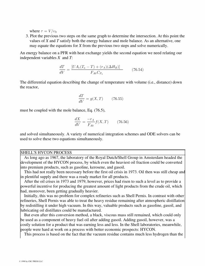
where ¿ = V=À0 3. Plot the previous two steps on the same graph to determine the intersection. At this point the
values of X and T satisfy both the energy balance and mole balance. As an alternative, onemay equate the equations for X from the previous two steps and solve numerically.
An energy balance on a PFR with heat exchange yields the second equation we need relating ourindependent variables X and T:
dT
dV=
[UAc(Ta ¡ T ) + (rA)(¢HR)]
FA0CPA
(76:54)
The differential equation describing the change of temperature with volume (i.e., distance) downthe reactor,
dT
dV= g(X; T ) (76:55)
must be coupled with the mole balance, Eq. (76.5),
dX
dV=
¡rA
FA0
f(X; T ) (76:56)
and solved simultaneously. A variety of numerical integration schemes and ODE solvers can beused to solve these two equations simultaneously.
SHELL'S HYCON PROCESSAs long ago as 1967, the laboratory of the Royal Dutch/Shell Group in Amsterdam headed the
development of the HYCON process, by which even the heaviest oil fraction could be convertedinto premium products, such as gasoline, kerosene, and gasoil.
This had not really been necessary before the first oil crisis in 1973. Oil then was still cheap andin plentiful supply and there was a ready market for all products.
After the oil crises in 1973 and 1979, however, prices had risen to such a level as to provide apowerful incentive for producing the greatest amount of light products from the crude oil, whichhad, moreover, been getting gradually heavier.
Initially, this was no problem for complex refineries such as Shell Pernis. In contrast with otherrefineries, Shell Pernis was able to treat the heavy residue remaining after atmospheric distillationby redistilling it under high vacuum. In this way, valuable products such as gasoline, gasoil, andlubricating oil distillates could be manufactured.
But even after this conversion method, a black, viscous mass still remained, which could onlybe used as a component of heavy fuel oil after adding gasoil. Adding gasoil, however, was acostly solution for a product that was earning less and less. In the Shell laboratories, meanwhile,people were hard at work on a process with better economic prospects: HYCON.
This process is based on the fact that the vacuum residue contains much less hydrogen than the
© 1998 by CRC PRESS LLC

lighter products. The aim, therefore, is to reduce the size of the molecules and to increase the ratioof hydrogen atoms to carbon atoms.
This ratio can be increased either by removing some carbon from the molecules or by attachinghydrogen to the atoms with the aid of a catalyst. Shell chose the latter approach and called itsprocess HYCON (hydroconversion).
This all sounds much simpler than it actually is. Reducing the size (cracking) of the largemolecules is only possible at high temperatures, but the problem with heating is that it produces aheavy deposit of carbon on the catalyst. This problem, and also the addition of hydrogen to themolecules, was solved by carrying out the process under high pressure. Another difficulty is thatthe asphaltenes (substances with a complex molecular structure) in the residue react very slowly.The reaction mixture therefore has to remain in the reactors for a long time. All in all, this means:several reactors in series, large amounts of catalyst, and high pressures and temperatures in thereactors.
There was another problem that had to be solved in the laboratories. The residue contains heavymetals, such as vanadium and nickel, which poison the catalyst. The solution for this is first of allto pass the residue through a number of reactors containing a specially developed catalyst whichremoves most of the metals. A technique was also developed to regenerate this catalyst during theprocess.
The HYCON process required the largest capital investment ever made by Shell in theNetherlands. HYCON in Pernis was put into operation at the beginning of 1989. (Courtesy of theShell Group.)
76.5 SummaryBy arranging chemical reaction engineering in a structure analogous to a French menu, we canstudy a multitude of reaction systems with very little effort. This structure is extremely compatiblewith a number of user-friendly ordinary differential equation (ODE) solvers. Using ODE solverssuch as POLYMATH, the student is able to focus on exploring reaction engineering problemsrather than crunching numbers. Thus, the teacher is able to assign problems that are more openended and give students practice at developing their creativity. Practicing creativity is extremelyimportant, not only in CRE, but in every course in the curriculum if students are to compete in theworld arena and succeed in solving the relevant problems that they will be faced with in thefuture.
Nomenclature
A frequency factor (appropriate units)
AC cross-sectional area, m2
Ci concentration of species i (i = A,B,C,D), mol/dm3
CPi heat capacity of species i, J/g/K
© 1998 by CRC PRESS LLC

DP particle diameter, m
E activation energy, J/mol
Fi entering molar flow rate of species i, mol/s
G superficial gas velocity g/m2/s
gc conversion factor
k specific reaction rate (constant), appropriate units
KA adsorption equilibrium constant (dm3/mol)
Ke equilibrium constant, appropriate units
L length down the reactor, m
Nt number of moles of species i, mol
P pressure, kPa
rt rate of formation of species i per unit volume, mol/s/dm3
rt' rate of formation of species i per unit mass of catalyst, mol/s/g
R ideal gas constant, J/mol/K
t time, s
T temperature, K
U overall heat transfer coefficient, J/(dm3 s K)
V volume, dm3
W catalyst weight, g
X conversion
y pressure drop parameter (P/P0)
yA mole fraction of A
a ambient temperatureA refers to species Acat catalyst density kg/m3
EB energy balanceMB mole balanceT total number of moles0 entering or initial condition® reaction order®P pressure drop parameter, g-1
¯ reaction order¢HR heat of reaction, J/mole A± change in the total number of moles per mole of A reacted² volume change parameter = yA0 ±Á porosity¹ viscosity, cp½ density, g/dm3
º volumetric flow rate, dm3/s
© 1998 by CRC PRESS LLC

£i Ni/NA0
Defining Terms
Batch reactor: A closed vessel (tank) in which there is no flow in or out of the vessel during thetime the reaction is taking place.
Continuous stirred tank reactor (CSTR): A reactor in which the reactant and products flowcontinuous into and out of (respectively) the tank. A reactor where the contents are wellmixed.
ODE solver: A user-friendly software package that solves ordinary differential equations, forexample, Mathematica, POLYMATH, Matlab.
Packed bed reactor: Usually a tubular reactor packed with solid catalyst pellets.Plug flow reactor: Usually a tubular reactor used for gas phase reactions in which it is assumed
there are no radial gradients in temperature or concentration as well as no dispersion ofreactants.
Semibatch reactor: A reactor (vessel) in which one of the reactants is placed in the reactor and asecond reactant is slowly added to the reactor.
References
Fogler,H. S. 1992. The Elements of Chemical Reaction Engineering, 2nd ed. Prentice Hall,Englewood Cliffs, NJ.
Shacham,M. and Cutlip, M. B. 1988. Applications of a microcomputer computation package inchemical engineering. Chemical Engineering Education. 12(1):18
Carbery,J. J. 1967. Applied kinetics and chemical reaction engineering, Chemical engineeringeducation, ed. R. L. Gorring and V. W. Weekman, p.89. American Chemical Society,Washington, DC.
Further Information
Professional OrganizationsThe American Institute of Chemical Engineers (three national meetings per year), 345 E. 47th St.,
New York, NY 10017. Phone (212) 705-7322.The American Chemical Society (several national meetings each year), 1155 16th St.,
Washington, DC 20036. Phone (202) 872-4600.
Special Meetings and ConferencesThe Engineering Foundation Conferences on Chemical Reaction Engineering, 345 E. 47th St.,
New York, NY 10017. Phone (212) 705-7835.International Symposia on Chemical Reaction Engineering (even years), sponsored by American
Institute of Chemical Engineers, American Chemical Society, Canadian Society forChemical Engineering, and the European Federation of Chemical Engineering.
© 1998 by CRC PRESS LLC

Professional JournalsAIChE Journal. Published monthly by the American Institute of Chemical Engineers, New York,
NY.Chem. Eng. Sci. Published semimonthly by Elsevier Science, Oxford, U.K.
© 1998 by CRC PRESS LLC
77The Scaleup of Chemical Reaction Systems
from Laboratory to Plant
77.1 General Considerations in the Rational Design of Chemical ReactorsReaction Kinetics Models and Reactor Models
77.2 Protocol for the Rational Design of Chemical ReactorsStep 1: Select the Type of Reactor for the Commercial Process • Step 2: Design the Laboratory to GenerateReaction Kinetics Data • Step 3: Use Statistically-Valid Experimental Programs and Models • Step 4:Develop Computer Programs for Reactor Simulation and Design • Step 5: Develop the EconomicallyOptimum Reactor Design • Step 6: Validate the Design in a Pilot Plant Reactor
J. B. CropleyUnion Carbide Corporate Fellow(Retired)
Scaleup is one of those overworked terms that has come to mean almost anything and everything,depending on who is using it. In this article we will use it very little, and then only to indicate thegeneric process of commercializing new chemical technology. The alternative to scaleup isrational design, which utilizes mathematical relationships and computer simulation to develop thebest design for the reactor. The mathematical relationships describe both the reaction kinetics andthe attributes of the reactor and its associated auxiliary equipment.
Geometric scaleup was practiced routinely in the chemical industry as a design protocol until afew decades ago, but, today, rational designbased on laboratory data and correlationshaslargely replaced it for most types of industrial chemical reaction systems. To understand why thisis so, it is necessary to note how the chemical industry has changed over the years.
Forty or 50 years ago, merely producing a chemical on an industrial scale was usually sufficientto ensure a profit for the manufacturer. Chemical processes were labor intensive, but capital andenergy were cheap and the selling price of a pound of finished product was typically several timesthe raw material cost. Furthermore, the environment had not yet been discovered either byindustry or by the public at large.
It was really unnecessary to design reactors rationally for most kinds of processes in that era,because any questions about productive capacity could be addressed simply by making the reactorlarger, raw material selectivities usually were not economically critical, and the large quantities ofenergy that were expended in complex distillation trains to remove by-products and impuritieswere both practicable and inexpensive.
In contrast, the petrochemical industry today utilizes chemical reactions that produce the desiredproducts much more directly and cleanly, with as little waste as possible. Raw material cost is
© 1998 by CRC PRESS LLC

frequently the largest component of the final product cost, and the crude product must not containunexpected by-products that the refining system cannot remove adequately and efficiently. Thefailure to meet tight product specifications can produce chemicals that either cannot be sold at allwithout expensive reprocessing or can be sold only for little more than their value as fuel.
In any case, both today's marketplace and concerns for the environment demand that chemicalreaction systems produce no more than extremely small amounts of waste or off-specificationproduct per pound of refined salable product. Reactors must be accurately designed and operatedbecause today's chemistry frequently is strongly dependent upon carrying out just the desiredamount of reaction in order to avoid the production of unwanted by-products by over-reaction.The energy efficiencies of refining systems strongly depend upon their receiving crude product ofuniform and predictable composition, because product specifications are usually tight and must bemet at minimum cost. Simply put, today's chemical reaction systems must operate as intended.
77.1 General Considerations in the Rational Design of ChemicalReactors
Reaction Kinetics Models and Reactor ModelsThe rational design of any type of reactor involves the marriage of one or more reaction kineticsmodels and a reactor model. It is important to recognize exactly what these two kinds of modelsdescribe:
• Reaction kinetics models describe the response of reaction rates to the reactionenvironmentthat is, to temperature and the concentrations of virtually everything in thesystemreactants, products, by-products, catalysts, and contaminants. For design purposes,it is necessary and sufficient that the kinetic model reflect the reaction stoichiometryaccurately and that it predict reaction rates accurately. It is not important that it reflect theactual reaction mechanism.
• Reactor models describe how the reaction environment is shaped by the geometry of thereactor, by physical processes like fluid dynamics and heat and mass transport, and byprocess variables and conditions such as mean reactor residence time and residence timedistribution, flow rate, pressure, and temperature.
These distinctions are subtle, but important. It is sufficient to remember that kinetics modelscontain only temperature and concentration terms, whereas reactor models may contain these aswell as everything else that influences the conduct of the reaction.
Kinetics of a Simple Hypothetical System of ReactionsReal systems will have their own individual structures and characteristics and will reflect theparticular stoichiometry of the reaction system at hand. In this chapter, we will use a general,somewhat simplified set of reactions and reactor equations for illustration. Consider the generalgroup of nr reactions presented below, in which chemical species A and B react to produceseveral products Pk according to the following scheme:
© 1998 by CRC PRESS LLC

®A1A + ®B1Br1¡!
ncX
1
(®k1Pk)
®A2A + ®B2Br2¡!
ncX
1
(®k2Pk)
...
®AjA + ®BjBrj¡!
ncX
1
(®kjPk)
...
®AnrA + ®Bnr
Brnr¡!
ncX
1
(®knrPk)
Kinetic models for the rational design of reaction systems will usually be of one of two basicmathematical forms, each given in moles/volume/time and describing the response of the reactionrates rj to temperature and concentration. For exponential models,
rj = Koj e¡
Eaj
RT CajA C
bjB C
P1j
P1: : : C
pnjPn
(77:1)
For hyperbolic models,
rj =Koj e
¡Eaj
RT CACB
1 +KAjCA +KBj
CB +Pnc
1 (KPkjCPk
)(77:2)
Each of these two types of kinetic models has its own preferred uses. Their development will bediscussed in a later section of this chapter. For now, assume that either of these types is to be usedin a combined kinetics and reactor model to predict reaction rates, as described in the followingsection.
Combined Kinetics and Reactor Models: The General Continuity EquationVirtually all combined reaction kinetics and reactor models utilize some form of the generalcontinuity equation for flow and reaction in an element of volume of some kind of reactor, such asthat shown in Fig. 77.1. In its simplest form, this equation states that the quantity of eachcomponent k that enters the volume element of the reactor must either leave, react, or accumulate:
© 1998 by CRC PRESS LLC

Fein Ckin = Feout Ckout ¡ Ve
nrX
1
(®kj rj ) +d(VeCke )
dtmol/time (77:3)
Figure 77.1 Flow and concentration in a volume element of a chemical reactor.
Different types of idealized reactors can be represented by this equation, simply by noting whatterms are not appropriate and eliminating them. Thus, a simple batch reactor has no flow in orout, and therefore terms containing F drop out. So, for a simple batch reactor,
d(VeCke )
dt=
nrX
1
(®kj rj)Ve (77:4)
which may be further simplified by canceling the Ve terms as well if the reaction volume isconstant. Note that the volume element in this case is simply the entire filled volume of thereactor, because the concentration is assumed to be uniform throughout.
A steady state continuous stirred tank reactor (CSTR) may have the same flow rate in and out,and the entire contents of the reactor comprise the volume element, as in the batch reactor. Thetime-derivative term is absent because the reactor is at steady state. The concentrations of allspecies in the reactor are the same as in the outlet. Thus we have, for the CSTR,
FCkin = FCkout ¡ V
nrX
1
(®kj rj ) (77:5)
which can be rearranged to
nrX
1
®kj rj =F (Ckout ¡ Ckin )
Vmol/volume/time (77:6)
Weight of catalyst, Wc , replaces reactor volume, V , for a catalytic reaction:
© 1998 by CRC PRESS LLC
nrX
1
®kj rj =F (Ckout ¡ Ckin )
Wc
mol/wt. catalyst/time (77:7)
This simple relationship makes the CSTR the preferred type of reactor for many kinds of kineticsstudies, in which the net rates of formation or disappearance [that is,
Pnr
1 (®kj rj) ]for eachindividual component can be observed directly.
For design purposes it is more convenient to integrate the unsteady state form of the generalcontinuity equation for the CSTR until the steady state concentrations are attained. (The modelwill behave very much as the real reactor would in this respect.) This procedure avoids the need touse constrained nonlinear estimation to predict the reactor outlet concentrations. Again, assumingthat flows in and out of the reactor are the same and that volume is constant,
d(Ck)
dt=
F (Ckin ¡ Ckout )
V+
nrX
1
(®kj rj ) mol/h (77:8)
The reactor model will comprise an equation like Eq. (77.8) for each component k in the CSTR.Another advantage of the unsteady state model is that stoichiometry is automatically preservedwithout the need for any constraints. It may be used readily to simulate a system comprising alarge number of components and reactions in a multistage system of CSTRs, which is otherwisemathematically intractable. And, of course, it may be used to study the dynamic behavior of thesystem as well. Therefore, it is the preferred design approach for multistage CSTR systems.
In the ideal steady state plug flow reactor, all elements of fluid that enter the reactor togethertravel down its length and exit together, having thus stayed in the reactor for identical lengths oftime. The volume element will be only a differential slice of the reactor cross section, denoted bydV . There will be no accumulation term, since the reactor is at steady state. The differentialconcentration difference across the differential volume element will be denoted by dC . Thus, Eq.(77.3) is once again applicable and simplifies to
FedCk =
nrX
1
(®kj rj)dVe (77:9)
If F changes as the reaction proceeds (as with many gas-phase reactions), then this can beaccommodated down the length of the plug flow reactor by modifying the above equation to
d(FeCk) =
nrX
1
(®kj rj)dVe
whence
© 1998 by CRC PRESS LLC

Fe
dCk
dVe
+ Ck
dFe
dVe
=
nrX
1
(®kj rj)dVe
dCk
dVe
=
Pnr
1 (®kj rj )
Fe
¡ Ck
Fe
dFe
dVe
(77:10)
Equation (77.10) describes the rate of change of concentration C of species k with volume downa plug flow reactor as a function of the reaction rates, concentration, and flow. It also reflects thechange in molar flow as the reaction proceeds.
A complete isothermal plug flow reactor model can readily be constructed using as many Eqs.(77.10) as there are components k , and as many kinetic models as there are reactions j . Fornonisothermal reactors, differential equations that describe the temperature changes down thelength of the reactor can be constructed in an analogous fashion, using the molar heat generationfor each reaction j and its corresponding reaction rate rj and heat transfer terms appropriate to thereactor type and geometry. For a multitube plug flow reactor with coolant on the outside of thetubes, the equation for reaction temperature (in degrees/volume) is as follows:
dTr
dVe
=
Pnr
1 (rj¢Hj) ¡ 4UDt
(Tr ¡ Tc)
Fe½pcp(77:11)
For coolant temperature,
dTc
dVe
=
4UDt
(Tr ¡ Tc)(Mode)
Fc½ccc(77:12)
Combined model equations like these are simplified in the sense that they do not account fordepartures from ideality because of nonideal mixing patterns in the case of stirred reactors, radialand axial diffusion effects in the case of tubular catalytic reactors, or the very specializedphenomena in fluidized beds and fixed-bed multiphase reactors. Yet they are surprisinglyapplicable in many industrial applicationsand will certainly be preferred to geometric scaleup inalmost all cases.
77.2 Protocol for the Rational Design of Chemical ReactorsGiven the distinctions between kinetics models and reactor models, as well as the characteristicsof combined reaction and reactor models, we can now establish a general protocol for rationaldesign that will apply to many types of chemical reactors in industrial situations. The protocolcomprises several steps, each of which is discussed in the following sections.
Step 1: Select the Type of Reactor for the Commercial Process
© 1998 by CRC PRESS LLC
First, select one or more potentially useful types of reactors for the commercial process. In manyinstances, the preferred reactor type will be known from past experience with the same or similarreactions. Even so, the scaleup characteristics and requirements for two important types ofreactionbatch reactions and solid-catalyzed reactionsmerit special attention here. The readeris referred to the large open literature for additional information. Texts by Froment and Bischoff[1979], and Levenspiel [1972]are classic and are particularly recommended.
Scaleup of Laboratory Batch Reactions
Plant-Size Batch Reactors. Many reactions are conveniently studied in laboratory batch reactors,but batch reactors often are not preferred for full-scale operations, particularly if the reaction israpid or if the planned plant will be quite large. Plant-size batch reactors are costly to operate,simply because they must be shut down, emptied, and recharged after a fairly shorttimetypically after only a few hours. This means that each reactor produces chemicals only on apart-time basis. As a consequence, batch reactors are usually preferred only for fairly high-pricedspecialty chemicals like pharmaceuticals that are produced at fairly low volumessay, under 50000 000 pounds per yearso that the required number and size of batch reactors are reasonable.
Ideal Plug Flow Reactors (PFRs). PFRs have the same residence-time distribution as ideal batchreactorsthat is, each element of feed is exposed to reaction conditions for exactly the samelength of time. They are particularly useful for high-volume, low-priced commodity chemicals,for which the laboratory batch reactor is preferred. If the reaction time is shortsay, under anhourit may be practicable to use some type of large-scale plug flow reactor (PFR) for the plant.A baffled column is a common example. More often than not, however, batch times are at leastseveral hours, and a plug flow continuous reactor would be too large and too costly for full-scaleplant use. However, PFRs are routinely used in industry for solid-catalyzed reactions, as discussedlater. The difference here is that the catalyst dramatically accelerates the reaction so thatlarge-scale plug flow reactors are quite practicable.
Single and Multistage CSTRs. The single-stage continuous stirred tank reactor (CSTR) isrelatively inexpensive and provides good temperature control, but it has a broad residence-timedistribution. This means that some of the feed may be under reaction for a very short time andsome may be in the reactor for an extended time. Also, concentrations of reactants and productsthroughout a CSTR will be the same as their exit concentrations, so that the reactions areconducted at minimum reactant concentration and maximum product concentration. This willmean a relatively slow reaction rate with maximum exposure of products to further reaction,which may lead to relatively low production rates and relatively high by-product formation rates.
Residence-Time Distribution and the Effects of Staging. To overcome some of thedisadvantages of both the PFR and CSTR reactors for reactions that are ideally carried out bybatch in the laboratory, several CSTRs are frequently connected in series. Their residence-timedistributions will be intermediate between the very narrow distributions of the batch reactor orPFR and the very broad distributions of the CSTR. Such a multistage reactor may be a goodcompromise, but it will not operate identically to the laboratory batch reactor.
© 1998 by CRC PRESS LLC

The effect of staging on a chemical reaction may be inferred from Fig. 77.2 , in which a simplesequential reaction of A going to B (desired) and then to C (undesired) is assumed. The figureshows that the batch reactor has the highest conversion of A and the highest yield of B , and thatthe CSTR has the lowest. The three- and five-stage CSTRs are intermediate between the batch andCSTR reactors. In practice, multistage systems of two to five CSTRs are common. Froment andBischoff [1979], Levenspiel [1972], and others have written extensively on residence-timedistribution and its impact on product yields and selectivities. These concepts are important to thesuccessful commercialization of batchwise laboratory reaction technology.
Figure 77.2 Effects of residence-time distribution.
Scaleup of Solid-Catalyzed Reactions
Solid catalysts are widely used in the chemical industry in several types of packed-bed reactors,slurry reactors, and fluidized bed reactors. Commercial processes frequently utilizesolid-catalyzed gas-phase reactions, but it is not uncommon for them to use both gas and liquidstreams, which greatly complicates the hydrodynamics. Reactors for solid-catalyzed reactions areall subject to scaleup problems because of differences in mass- and heat-transport in large-scaleequipment and laboratory equipment.
© 1998 by CRC PRESS LLC

Packed-bed reactors are probably used more than any other type for solid-catalyzed reactions.They tend to have residence-time distributions that closely approach plug flow, especially forplant-scale single-phase systems in which the bed length is at least 5 to 10 meters. Their narrowresidence-time distribution makes them preferred from the standpoint of being able to controlproduct distribution in systems of sequential reactions. Equations (77.10)−(77.12) are appropriatehere.
Shell-and-tube packed-bed reactors have excellent heat removal characteristics, particularly ifthe tube diameters are fairly smallsay, one to one-and-a half inches. A schematic of a typicalplant-scale shell-and-tube reactor is shown in Fig. 77.3 . Although relatively expensive, suchreactors can usually be designed rationally with confidence.
Figure 77.3 Conceptual shell-and-tube fixed-bed reactor. (Source: Reproduced with permission of theAmerican Institute of Chemical Engineers from Cropley, J. B. 1990. Development of optimal fixed bedcatalytic reaction systems. Chemical Engineering Progress 86(2): 32−39. American Institute of ChemicalEngineers, New York, February 1990. ©1990 AIChE. All rights reserved.)
Adiabatic packed-bed reactors are attractive because of their relatively low cost. (At theirsimplest, they can be little more than an empty tank filled with catalyst pellets.) However, theysuffer from the effects of an uncontrolled reaction temperature and tend to drift towards themaximum possible attainable temperature, which usually means that the limiting reactant iscompletely consumed or that equilibrium has been reached. This is a desirable property for somereactions (e.g., hydrogenations), but usually the chemical selectivity suffers as a result. Unwanted
© 1998 by CRC PRESS LLC
by-products may result, even in hydrogenation systems. The adiabatic reactor usually is notrecommended where temperature control is important.
Multiphase packed-bed reactors (e.g., trickle beds) are widely used, but the transport ofreactants and products between the flowing gas and liquid and the solid catalyst is a majoruncertainty. A lot of work remains to be done before the rational design of these reactors can beundertaken with confidence. Instead, back-and-forth experimentation and mathematical analysisof the hydrodynamics is necessary. Suffice it to note here that the transport characteristics ofmultiphase reactors are different in each of the several hydrodynamic regimes that may beexperienced (e.g., trickle flow, bubbling flow, pulsing flow, slug flow, mist flow). A prioricalculations using relationships from the open literature can often predict whether reactionkinetics or mass transfer will limit the reactor's performance, and the preliminary designsometimes can be developed rationally thereafter. Pilot-scale experimental verification of theperformance of the final design in the same hydrodynamic region as the plant reactor isnonetheless essential to avoid surprises. There is an abundant literature on this type of reactor, andthe excellent text by Ramachandran and Chaudhari [1983]is a good place to obtain an introductionto this complex technology.
Fluidized-bed reactors are widely used in fluidized catalytic cracking, the manufacture ofpolyethylene and polypropylene, the manufacture of silicones from silicon, and some othercommercial reactions. The fluid and solid dynamics of these systems are extremely complex, andavailable models are best described as learning models, rather than predictive models for reactionsystem design. Scaleup is typically done incrementally in a series of pilot-plant reactors. Despitethe well-known advantages of these systems for some purposes (excellent temperature control,absence of diffusional and transport restrictions), the decision to use fluidized systems for newapplications must not be taken lightly. Although the solid phase may usually be assumed to bewell mixed, the residence-time distribution of the fluid phase is complex and largelyunpredictable. It follows that the performance of a scaled-up reactor is also largely unpredictableif the fluid-phase residence-time distribution is important.
It is worth noting that, with few exceptions, all successful commercial fluidized bed reactionsystems involve a solid phase that is always in some kind of rapid transition. Fluidizedcatalytic-cracking catalyst becomes coked and inactive in only 3 to 5 seconds and is continuouslyremoved from the fluidized riser reactor and regenerated by burning in dilute oxygen. The solidphase is in fact the product polyolefin in fluidized systems like Union Carbide's Unipolpolyolefins process. Dimethyldichloro silane (an intermediate in the manufacture of silicone oilsand other products) is manufactured by reacting silicon metal and methyl chloride in afluidized-bed reactor. Here, the silicon reactant is in the form of a fine metal powder that iscontinually consumed by the reaction and that comprises the solid phase in the reactor. Anexception to the above observation is the Badger process for the manufacture of phthalicanhydride in a fluidized-bed reactor, in which the solid is a catalyst that is not undergoing anyrapid change. It is carried out in a fluidized bed because the temperature control is important to theprocess.
The technology of fluidization has been studied in depth since before World War II andcontinues to be studied still because of its importance in those industries that depend upon it.AIChE has published several volumes on fluidization in its symposium series, and more appear
© 1998 by CRC PRESS LLC
periodically. Some excellent texts exist on fluidization phenomena; that by Kunii and Levenspiel[1969]is considered a classic.
Slurry reactors are attractive for many gas-liquid systems that are catalyzed by solid catalysts,but their design is nearly as complicated as for fluidized-bed systems. There is an extensive openliterature on this type of reactor. The Air Products Company has published a number of reports onwork done under contract for the U.S. Department of Energy and has a large pilot plant atLaPorte, Texas, for the manufacture of methanol and higher alcohols from CO and hydrogen.These reports and the text on multiphase reactors by Ramachandran and Chaudhari [10]arerecommended.
Step 2: Design the Laboratory to Generate Reaction Kinetics DataThe second step in the protocol for rational design is to design the laboratory reaction systemspecifically to generate kinetics rate data. By now it should be clear that the kinetic model is thelink between the laboratory operations and the large-scale plant design. The experimental reactorfor kinetics studies will ordinarily not look at all like the final plant reactor. Rather, it will bedesigned to obtain the kinetic data necessary for kinetic model development. Three primary typesof laboratory reactor are suitable for design-quality kinetics studies:
• The batch reactor• The long-tube reactor with sample points along its length• The continuous stirred tank reactor, or CSTR
The following paragraphs discuss each of these types, with the emphasis upon what kinds ofreactions are suitable for each and any special considerations that may apply.
Laboratory batch reactors are found in virtually limitless variety in most industrial chemicallaboratories. For kinetics studies it is imperative that chemical analyses be obtained at severaltimes during the reaction period. This sometimes poses problems if the reaction starts before thedesired reaction temperature has been reached or if the reaction proceeds so quickly that multiplesamples are not practical. Likewise, the loss of reacting volume due to sampling may beimportant, particularly if a solid catalyst is involved. Both of these problems are best handledduring mathematical analysis of the data by forcing the simulated time-temperature andtime-reacting volume profiles to be the same as the observed ones.
Batch laboratory reactors are suitable for either uncatalyzed or catalyzed liquid-phase orgas-liquid reactions. In special situations they may be useful for gas-phase reactions as well. Theyare especially useful for slurry-catalyzed reactions, but they can also be used with pelletedcatalysts, provided that provision is made to retain the pellets in a basket or container throughwhich the fluid passes. Both the Berty reactor [see Fig. 77.4 and (Berty, 1974)] and the Carberryrotating basket reactor [Levenspiel, 1972]have been widely used for batchwise kinetic studies ofcatalytic reactions, although their best use is probably in continuous gas-phase kinetics studies.
Figure 77.4 The Berty reactor for experimental catalyst testing and kinetics. (Source: Reproduced withpermission of the American Institute of Chemical Engineers from Cropley, J. B. 1990. Development ofoptimal fixed bed catalytic reaction systems. Chemical Engineering Progress 86(2): 32−39. American
© 1998 by CRC PRESS LLC

Institute of Chemical Engineers, New York, February 1990. ©1990 AIChE. All rights reserved.)
Long-tube reactors for kinetics studies will typically be of a length to promote both plug flowcharacteristics and good mass and heat transfer so that these physical processes do not mask thechemical reaction rates. Tube length per se is not critical, although it is highly desirable that thelength-to-diameter ratio be at least 100:1 to avoid the effects of axial mixing and departure fromplug flow behavior. Tube diameter is not particularly important, but should be small enough toensure good heat transfer. If solid-catalyst pellets are to be used, the tube diameter should be nomore than four or five pellet diameters to avoid radial temperature gradients. It is important thatprovision be made for samples to be taken at multiple points down the tube length. Reactors likethese are particularly well suited for kinetics studies using plant-scale catalyst pellets and for the
© 1998 by CRC PRESS LLC
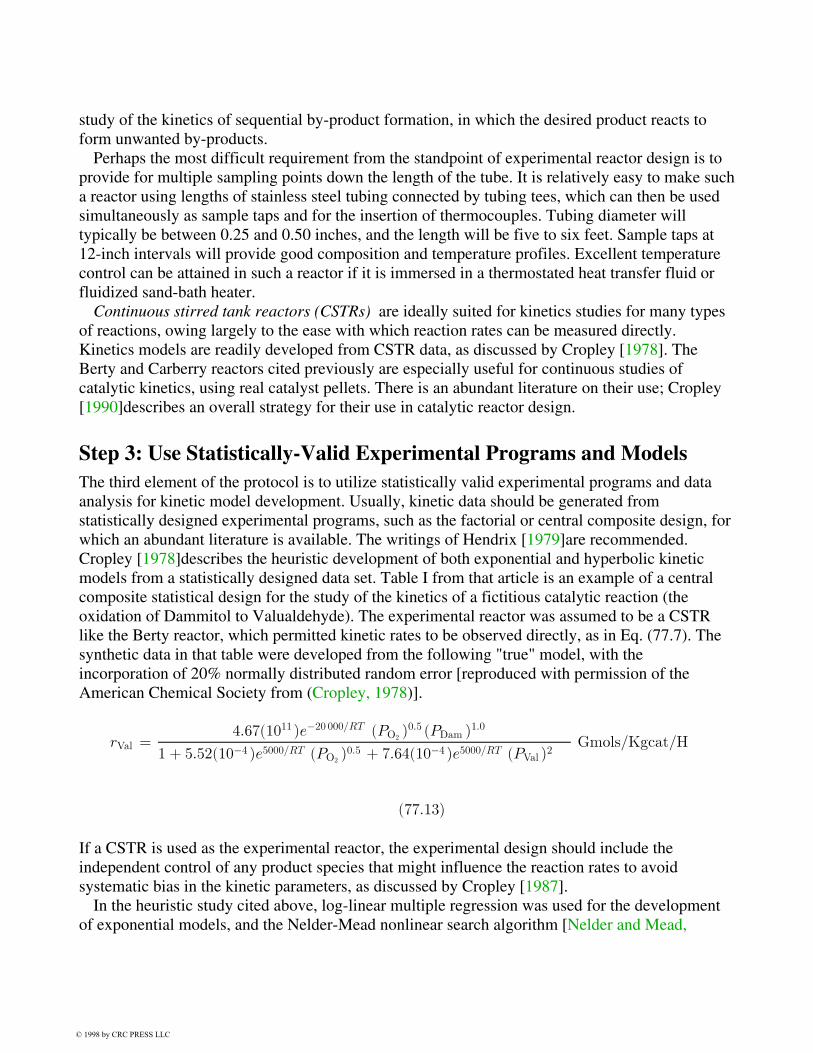
study of the kinetics of sequential by-product formation, in which the desired product reacts toform unwanted by-products.
Perhaps the most difficult requirement from the standpoint of experimental reactor design is toprovide for multiple sampling points down the length of the tube. It is relatively easy to make sucha reactor using lengths of stainless steel tubing connected by tubing tees, which can then be usedsimultaneously as sample taps and for the insertion of thermocouples. Tubing diameter willtypically be between 0.25 and 0.50 inches, and the length will be five to six feet. Sample taps at12-inch intervals will provide good composition and temperature profiles. Excellent temperaturecontrol can be attained in such a reactor if it is immersed in a thermostated heat transfer fluid orfluidized sand-bath heater.
Continuous stirred tank reactors (CSTRs) are ideally suited for kinetics studies for many typesof reactions, owing largely to the ease with which reaction rates can be measured directly.Kinetics models are readily developed from CSTR data, as discussed by Cropley [1978]. TheBerty and Carberry reactors cited previously are especially useful for continuous studies ofcatalytic kinetics, using real catalyst pellets. There is an abundant literature on their use; Cropley[1990]describes an overall strategy for their use in catalytic reactor design.
Step 3: Use Statistically-Valid Experimental Programs and ModelsThe third element of the protocol is to utilize statistically valid experimental programs and dataanalysis for kinetic model development. Usually, kinetic data should be generated fromstatistically designed experimental programs, such as the factorial or central composite design, forwhich an abundant literature is available. The writings of Hendrix [1979]are recommended.Cropley [1978]describes the heuristic development of both exponential and hyperbolic kineticmodels from a statistically designed data set. Table I from that article is an example of a centralcomposite statistical design for the study of the kinetics of a fictitious catalytic reaction (theoxidation of Dammitol to Valualdehyde). The experimental reactor was assumed to be a CSTRlike the Berty reactor, which permitted kinetic rates to be observed directly, as in Eq. (77.7). Thesynthetic data in that table were developed from the following "true" model, with theincorporation of 20% normally distributed random error [reproduced with permission of theAmerican Chemical Society from (Cropley, 1978)].
rVal =4:67(1011 )e¡20 000=RT (PO2
)0:5 (PDam )1:0
1 + 5:52(10¡4 )e5000=RT (PO2)0:5 + 7:64(10¡4 )e5000=RT (PVal )2
Gmols/Kgcat/H
(77:13)
If a CSTR is used as the experimental reactor, the experimental design should include theindependent control of any product species that might influence the reaction rates to avoidsystematic bias in the kinetic parameters, as discussed by Cropley [1987].
In the heuristic study cited above, log-linear multiple regression was used for the developmentof exponential models, and the Nelder-Mead nonlinear search algorithm [Nelder and Mead,
© 1998 by CRC PRESS LLC
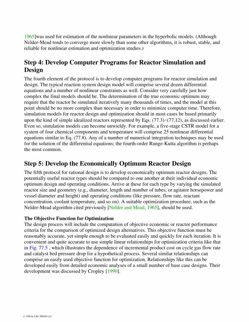
1965]was used for estimation of the nonlinear parameters in the hyperbolic models. (AlthoughNelder-Mead tends to converge more slowly than some other algorithms, it is robust, stable, andreliable for nonlinear estimation and optimization studies.)
Step 4: Develop Computer Programs for Reactor Simulation andDesignThe fourth element of the protocol is to develop computer programs for reactor simulation anddesign. The typical reaction system design model will comprise several dozen differentialequations and a number of nonlinear constraints as well. Consider very carefully just howcomplex the final models should be. The determination of the true economic optimum mayrequire that the reactor be simulated iteratively many thousands of times, and the model at thispoint should be no more complex than necessary in order to minimize computer time. Therefore,simulation models for reactor design and optimization should in most cases be based primarilyupon the kind of simple idealized reactors represented by Eqs. (77.3)−(77.12), as discussed earlier.Even so, simulation models can become unwieldy. For example, a five-stage CSTR model for asystem of four chemical components and temperature will comprise 25 nonlinear differentialequations similar to Eq. (77.8). Any of a number of numerical integration techniques may be usedfor the solution of the differential equations; the fourth-order Runge-Kutta algorithm is perhapsthe most common.
Step 5: Develop the Economically Optimum Reactor DesignThe fifth protocol for rational design is to develop economically optimum reactor designs. Thepotentially useful reactor types should be compared to one another at their individual economicoptimum design and operating conditions. Arrive at these for each type by varying the simulatedreactor size and geometry (e.g., diameter, length and number of tubes, or agitator horsepower andvessel diameter and height) and operating conditions (like pressure, flow rate, reactantconcentration, coolant temperature, and so on). A suitable optimization procedure, such as theNelder-Mead algorithm cited previously [Nelder and Mead, 1965], should be used.
The Objective Function for OptimizationThe design process will include the computation of objective economic or reactor performancecriteria for the comparison of optimized design alternatives. This objective function must bereasonably accurate, yet simple enough to be evaluated easily and quickly for each iteration. It isconvenient and quite accurate to use simple linear relationships for optimization criteria like thatin Fig. 77.5 , which illustrates the dependence of incremental product cost on cycle gas flow rateand catalyst bed pressure drop for a hypothetical process. Several similar relationships cancomprise an easily used objective function for optimization. Relationships like this can bedeveloped easily from detailed economic analyses of a small number of base case designs. Theirdevelopment was discussed by Cropley [1990].
© 1998 by CRC PRESS LLC
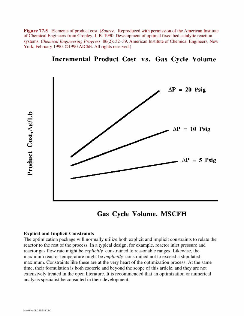
of Chemical Engineers from Cropley, J. B. 1990. Development of optimal fixed bed catalytic reactionsystems. Chemical Engineering Progress 86(2): 32−39. American Institute of Chemical Engineers, NewYork, February 1990. ©1990 AIChE. All rights reserved.)
Explicit and Implicit ConstraintsThe optimization package will normally utilize both explicit and implicit constraints to relate thereactor to the rest of the process. In a typical design, for example, reactor inlet pressure andreactor gas flow rate might be explicitly constrained to reasonable ranges. Likewise, themaximum reactor temperature might be implicitly constrained not to exceed a stipulatedmaximum. Constraints like these are at the very heart of the optimization process. At the sametime, their formulation is both esoteric and beyond the scope of this article, and they are notextensively treated in the open literature. It is recommended that an optimization or numericalanalysis specialist be consulted in their development.
Figure 77.5 Elements of product cost. (Source: Reproduced with permission of the American Institute
© 1998 by CRC PRESS LLC

Step 6: Validate the Design in a Pilot Plant ReactorThe final step in the protocol for rational design is to validate the overall optimum design byoperation of a pilot reactor system. This is the only time that scaleup, per se, will be considered inthe design. Here again, this may not necessarily involve a pilot reactor that is geometricallysimilar to the final plant design, although it may be in some cases. It will be important to designthe pilot reactor to be able to confirm the predicted reaction yields and selectivities under designconditions. It is vital that all important recycle streams be incorporated into the pilot plantsystemwhich will then be, to the extent possible, a scaled-down version of the integratedcommercial process. Typically, recycle streams include previously unreacted raw materials,by-products that can be reverted to useful product, or potential pollutants that can simply bedestroyed by further reaction in the reactor. But trace components and minor species can build upin recycle systems to many times their single-pass concentrations, and they may have adverseeffects on catalyst life, equilibrium conversion, crude product quality, and so on. It is importantthat the effects of recycled species be incorporated into the kinetics model for operationalmonitoring and control. Unanticipated effects of recycle streams probably account for a significantfraction of scaleup problems in commercial systems.
Finally, please note that this chapter has not discussed the size of the pilot plant reactorsizeper se really is not an issue. What is important is that it function in such a way as to test therational design before it is built. More discussion of process optimization and validation can befound in Cropley [1990].
Nomenclature
Uppercase Symbols
A, B Reactants
Ck Concentration of kth chemical component, in mols/volume units
Dt Tube diameter, in linear units
Dam Fictitious component Dammitol
Fe, Fc Flow rate of process fluid (e) or of coolant (c) through the volume element, involume/time units
¢Hj Heat of reaction of jth reaction in heat/mol units
Koj, Eaj Arrhenius kinetic parameters for reaction j
KAj,KBj,KPkj
Kinetic parameters associated with reactants A and B and products Pk for reaction j
Mode (-1) if coolant flows countercurrent to process stream flow
(+1) if flows are cocurrent(0) if coolant is isothermal (infinite flow, boiling, etc.)
© 1998 by CRC PRESS LLC

Pk Reaction products
R Gas constant, typically 1.987 cal/Gmol/K for kinetics models
Tr, Tc Reaction and coolant temperature, respectively
U Overall heat transfer coefficient, in heat/area/time/temperature units
Val Fictitious component Valualdehyde
Ve An element of volume of any reactor
Wc Weight of catalyst in the reactor, in weight units
Lowercase and Greek Symbols
®kj Stoichiometric coefficient for species k in reaction jcc Heat Capacity of coolant stream, in heat/mass/temperature unitscp Heat capacity of flowing process stream, in heat/mass/temperature
unitsnc Total number of products k in the kinetic modelnr Number of reactions j in the kinetic modelnt Number of tubes in a tubular reactor½p; ½c Density of process stream (p) or coolant (c), in mass/volume unitsr Kinetic reaction rate, mols/volume/time (or mols/wt. catalyst/time for catalytic
reactions)t Time, in units consistent with F, r, U
Defining Terms
Chemical reaction: The chemical transformation of one or more reactant species into one ormore chemical products, usually with the evolution or absorption of heat.
Chemical reactor: The vessel in which a chemical reaction is conducted.Continuous stirred tank reactor: A well-mixed continuous reactor, characterized by a broad
residence time distribution.Conversion: The fraction of a feed component that undergoes chemical transformation in the
reactor.Plug flow reactor: A type of reactor in which all entering elements of fluid have the same
residence time. The residence time distribution is thus extremely narrow.Residence time: The amount of time that a reactive mixture spends in a chemical reactor.Residence-time distribution (RTD): The spread of residence times that different elements
entering a reactor spend in it. RTD is one of the distinguishing characteristics of differentreactor types.
Selectivity: The fraction of all of a feed component that is converted to form a specified product.Yield: The fraction of all of a feed component entering a reactor that is converted to a specified
product. Yield = (Selectivity)(Conversion).
References
Berty, J. M. 1974. Reactor for vapor-phase catalytic studies. Chem. Eng. Prog. 70: 57−584.Cropley, J. B. 1978. Heuristic approach to complex kinetics. In Chemical Reaction Engineering
Houston, D. Luss and V. Weekman, eds. ACS Symposium Series 65. Paper 24.Cropley, J. B. 1987. Systematic errors in recycle reactor kinetics studies. Chemical Engineering Pro
© 1998 by CRC PRESS LLC
−50. American Institute of Chemical Engineers, New York.Cropley, J. B. 1990. Development of optimal fixed bed catalytic reaction systems. Chemical Engine
−39. American Institute of Chemical Engineers, New York.Froment, G. F. and Bischoff, K. B. 1979. Chemical Reactor Analysis and Design. John Wiley
& Sons, New York.Hendrix, C. D. 1979. What every technologist should know about experimental design. Chemtech. 9
−174. American Chemical Society, Washington, DC.Kunii, D. and Levenspiel, O. 1969. Fluidization Engineering. John Wiley & Sons, New York.Levenspiel, O. 1972. Chemical Reaction Engineering, 2nd ed. John Wiley & Sons, New York.Nelder, J. A. and Mead, J. R. 1965. A simplex method for function minimization. Computer Journal
−313.Ramachandran, P. A. and Chaudhari, R. V. 1983. Three-Phase Catalytic Reactors. Gordon and
Breach Science, New York.
Further Information
Professional OrganizationsThe American Institute of Chemical Engineers (three national meetings per year). 345 E. 47th St.,
New York, NY 10017. Phone (212) 705-7322.The American Chemical Society (several national/regional meetings each year). 1155 16th St.,
N.W., Washington, DC, 20036. Phone (202) 872-4600.
Special Meetings and ConferencesThe Engineering Foundation Conferences on Chemical Reaction Engineering. 345 East 47th
Street, New York, NY 10017. Phone (212) 705-7835.International Symposia on Chemical Reaction Engineering (even years). Sponsored by American
Institute of Chemical Engineers, American Chemical Society, Canadian Society forChemical Engineering, and the European Federation of Chemical Engineering.
© 1998 by CRC PRESS LLC