kinemtics of machinery objectives assignments tutorial problems
TRANSCRIPT
10.KINEMATICS OF MACHINERY – ( A040309 )
10.1. SYLLABUS
UNIT-I MECHANISMS : Elements or Links – Classification - Rigid Link, flexible and fluid link - Types of kinematics pairs - Types of Constrained motion - Kinematic chain - Mechanism – Machine – Structure - Inversions of mechanism - Inversions of quadric cycle chains, single and double slider crank chains, Mechanical advantage – Grubler’s Criterion.UNIT-II KINEMATICS : Velocity and acceleration - Motion of link in machine -Determination of Velocity and acceleration - Graphical method - Application of relative velocity method.Plane motion of body : Instantaneous center of rotation - Centrods and axodes - Three centers in line theorem - Graphical determination of Instantaneous centre, determination of angular velocity of points and links by Instantaneous centre method.Kleins construction, Coriolis acceleration - determination of Coriolis component of acceleration, Diagrams for simple mechanisms and determination of angular velocity of points and links.Analysis of Mechanisms : Analysis of slider crank chain for displacement, velocity and acceleration of slider - Acceleration diagram for a given mechanism.UNIT-III STRAIGHT LINE MOTION MECHANISMS: Exact and approximate copied and generated types – Peaucellier - Hart - Scott Russul - Grasshopper –Watt - Tchebicheff’s and Robert Mechanism – Pantographs.Steering Gears:Conditions for correct steering - Davis Steering gear, Ackerman’s steering gear Hooke's Joint: Single and Double Hooke's joint – Velocity ratio – Application – Problems. UNIT-IV CAMS: Definitions of cam and followers & their uses,Types of followers and cams, Uniform velocity Simple harmonic motion and uniform acceleration,Maximum velocity and maximum acceleration during outward return strokes in the above 3 cases.Drawing a cam profiles Analysis of motion of followers Roller follower Circular cam with straight, concave and convex flanks. Cams with specified contours Cams with cycloidal motionUNIT-V HIGHER PAIRS: Friction wheels and toothed gears – types, Law of gearing, condition for constant velocity ratio for transmission of motion, Velocity of sliding, Form of teeth: cycloidal and involutes profiles.Phenomena of interferences - Methods of interference, Condition for minimum number of teeth to avoid interference, expressions for arc of contact and path of Contact of pinion & gear and Pinion & Rack arrangements. Introduction to Helical, Bevel and worm gearing.GEAR TRAINS: Introduction - Types – Simple, Compound and reverted gear trains, Epicyclic gear Train. Methods of finding train value or velocity ratio of Epicyclic gear trains. Selection of gear box-Differential gear for an automobile.TEXT BOOKS: 1. Theory of Machines and Mechanisms / Joseph E Shigley / OXFORD / 3rd Edition2. Theory of Machines / Thomas Bevan / Pearson / 3rd EditionREFERENCE BOOKS: 1. Theory of Mechanisms and Machines / Jagadish Lal / Metropolitan Book Company2. Theory of Machines / S S Rattan / Tata Mc Graw Hill Publishers3. Kinematics & Dynamics of Machinery / Norton / TMH4. Theory of Machines / Sadhu Singh / Pearson5. Mechanism and Machine Theory / J S Rao and R V Dukkipati / New Age6. Theory of Machines / R K Bansal / Lakshmi Publications
MLR Institute of Technology,Dundigal,Hyderabad-500 043 Page 1

10.2. UNIT WISE PLANNER
Unit No. Total no of Lectures
I 12
II 15
III 10
IV 11
V 16
10.3. SESSION PLANNER
MLR Institute of Technology,Dundigal,Hyderabad-500 043 Page 2
MLR Institute of Technology,Dundigal,Hyderabad-500 043 Page 3
S.No
Unit Class TopicText / Ref. book
DateRemar
ks
1
UNIT-1
L1Introduction of the subject & Syllabus, Objective and Applications of Kinematics of Machinery
2 L2MECHANISMS : Introduction, Rigid Body, Resistant Body, Elements or Links , Classification, Rigid Link, Flexible Link and Fluid Link, Structure, Machine.
3 L3Kinematics Pairs, Types of Kinematics Pairs - sliding, turning, rolling, screw and spherical pairs, closed & open pairs, Higher Pair & Lower Pair.
4L4
Types of Constrained motion - completely, partially or successfully constrained and incompletely constrained motion
5 L5
Kinematic Chain, Mechanism, Machine and Structure. Types of Mechanisms, Classification of Machines, Types of Joints, Binary, Terinary and Quaternary joints
6 L6Degrees of Freedom for Planar Mechanisms, Application of Kutzbach criterion, Grubler’s Criterion
7 L7Inversion of mechanisms, Types of Kinematic Chains, Four Bar Chain(Quadric Cycle Chain), Grashof’s Law
8 L8Inversions of Quadratic Cycle ( 4 Bar ) Chain, Beam Engine, Coupling rod of Locomotive, Watt’s indicator Mechanism
9 L9Single Slider Crank Chain, Inversions: Pendulum Pump, Oscillating Cylinder Engine, Rotary IC Engine
10L10
Crank and Slotted Lever Quick Return Motion Mechanism, Whitworth Quick Return Motion Mechanism, Problems.
11L11
Double Slider Crank Chain, Inversions: Elliptical Trammels Scotch Yoke Mechanism, Oldham’s Coupling.
12 L12 Additional Problems & Class Test 1
13
UNIT-2
L13KINEMATICS : Velocity and acceleration - Motion of a link in machine
14L14 Determination of Velocity & Accelaration
15 L15 Determination of Velocity & Accelaration diagrams
16 L16 Velocity & Accelaration diagrams, Graphical method
17 L17 Application of relative velocity method - four bar chain.
18 L18 Relative velocity method : Problems.
19 L19Plane motion of body : Instantaneous center of rotation
20 L20 Centrodes & Axodes, Three centers in line theorem
21 L21 Graphical representation of instantaneous centres
22 L22Determination of angular velocity of points and links by Instantaneous centre method
23 L23 Kleins construction, Coriolis acceleration,
24 L24 Determination of Coriolis component of acceleration

10.4. QUESTION BANK
10.4.1.1.SUBJECTIVE QUESTIONS 1. (a) What is a Kinematic pair? Explain different types of Kinematic pairs as classified by
relative motion. (b) The distance between the axes of two parallel shafts is 1cm. The shafts are connected by
Oldham coupling. Find the maximum Kinetic energy of the intermediate piece of mass 5 kg when the shafts revolve at 300 rpm.
2. (a) Name the two inversions obtained by fixing the crank of a single slider crank chain. Describe them with neat sketches.
(b) In a Whitworth quick return motion mechanism, as shown in figure. lengths of driving crank AC =90mm, the distance between fixed centers CD=60mm, the length of slotted lever, AP
is 180mm and the length of the connecting rod PR is 162mm. Find the ratio of the time of cutting stroke to that of return stroke and also the length of effective stroke.
3. (a) Differentiate betweeni). Element and kinematic Linkii). Mechanism and machineiii). Closed pair and unclosed pairiv). Lower pair and Higher pair.
(b) In a Whitworth quick return motion mechanism, the length of the driving link is 75 mm while the distance between the fixed centers is 50 mm. Find the ratio of the time of cutting stroke
to that of return stroke.
4. Two shafts have their axes parallel and 2.5 cm apart. One of the shafts drives the other through an Oldham coupling. Sketch the arrangement and prove that the angular velocity ratio is unity. If the speed of the shaft is 100 rpm, what is the maximum velocity of sliding in cm per minute of the intermediate disc on either of the side discs?
5. (a) Define: Kinematic link and Kinematic chain. (b) Describe various inversions of a slider crank mechanism giving examples.
6. (a) State the six types of lower pairs, explain with the help of neat sketches. (b) State Grashof's law and discuss all the possible inversions of four bar chain with neat
sketches. Give one application of each inversion
7. (a) What is the difference between lower pair and higher pair? Give examples for each type. (b) Describe the three inversions of Double slider crank chain with neat sketches.
MLR Institute of Technology,Dundigal,Hyderabad-500 043 Page 4

8. (a) What is higher pair? How gears are classified? (b) Two gears in mesh have a module of 10 mm and a pressure angle of 25o. The pinion has
20 teeth and the gear has 52. The addendum on both the gears is equal to one module. Determinei). The number of pairs of teeth in contact.ii). The angles of action of the pinion and the wheel.iii). The ratio of the sliding velocity to the rolling velocity at the pitch point and at the beginning and end of engagement.
9. (a) Distinguish between closed and unclosed type kinematic pairs. Give examples for each type(b) Explain completely, successfully and incompletely constrained motions of kinematics pairs with examples.
10. (a) Two parallel shafts, with the distance between their axes being 20mm, are connected by an Oldham coupling. If the speed of the shafts is 400rpm, find the maximum speed of sliding of each tongue of the intermediate piece along its groove.
(b) Find the distance between the fixed centers of a whit worth quick return motion mechanism if the length of driving link is 35mm, return stroke is 125 mm and time ratio of cutting to return stroke is 1.75.
10.4.1.2.OBJECTIVE QUESTIONS:
1. Match the items in columns I and II [GATE-2006]Column I Column II
P. Higher kinematic pair 1. Grubler's equation
Q. Lower kinematic pair 2. Line contactR. Quick return mechanism 3. Euler's equation
S. Mobility of a linkage 4. Planer
5. Shaper6. Surface contact
(a) P-2, Q-6, R-4, S-3 (b) P-6, Q-2, R-4, S-1(c) P-6, Q-2, R-5, S-3 (d) P-2, Q-6, R-5, S-1
2. The minimum number of links in a single degree-of-freedom planarmechanism with both higher and lower kinematic pairs is [GATE-2002](a) 2 (b) 3 (c) 4 (d) 5
3. The number degrees of freedom of a planar linkage with 8 links and 9simple revolute joints is [GATE-2005](a)1 (b) 2 (c) 3 (d)4
4. When a cylinder is located in a Vee-block, then number of degrees offreedom which are arrested is [GATE-2003](a) 2 (b) 4 (c) 7 (d) 8
5. The number of degrees of freedom of a five link plane mechanism with fiverevolute pairs as shown in the figure is [GATE-1993]
MLR Institute of Technology,Dundigal,Hyderabad-500 043 Page 5

(a) 3 (b)4 (c)2 (d) 1
6. Match the following with respect to spatial mechanisms. [GATE-2004]Type of Joint Degrees of constraint
P. Revolute 1. ThreeQ. Cylindrical 2. FiveR. Spherical 3. Four4. Two5. Zero
(a) P-1 Q-3 R-3 (b) P-5 Q-4 R-3 (c) P-2 Q-3 R-1 (d) P-4 Q-5 R-3
7. A planar mechanism has 8 links and 10 rotary joints. The number ofdegrees of freedom of the mechanism, using Grubler's criterion, is [GATE-2008](a) 0 (b) 1 (c) 2 (d) 3
8. Match the approaches given below to perform stated kinematics/dynamicsanalysis of machine. [GATE -2009]
Analysis ApproachP. Continuous relative rotation 1. D’Alembert’s principleQ. Velocity and acceleration 2. Grubler’s criterionR. Mobility 3. Grashoff’s law S. Dynamic-static analysis 4. Kennedy’s theoram
(a) P-1, Q-2, R-3, S-4 (b) P-3, Q-4, R-2, S-1 (c) P-2, Q-3, R-4, S-1 (d) P-4, Q-2, R-1, S-3
9. Which of the following statements is incorrect [GATE-2010](a) Grashof's rule states that for a planar crank-rocker four bar mechanism, thesum of the shortest and longest link lengths cannot be less than the sum of theremaining two link lengths.(b) Inversions of a mechanism are created-by fixing different links one at a time.(c) Geneva mechanism is an intermittent motion device.(d) Gruebler's criterion assumes mobility of a planar mechanism to be one.
10. In a four-bar linkage, S denotes the shortest link length, L is the longestlink length, P and Q are the lengths of other two links. At least one of the
MLR Institute of Technology,Dundigal,Hyderabad-500 043 Page 6

three moving links will rotate by 360o if [GATE-2006](a) S + L ≤ P + Q (b) S + L > P + Q (c) S + P≤L + Q (d) S + P > L + Q
11. The number of inversions for a slider crank mechanism is [GATE-2006](a) 6 (b) 5 (c) 4 (d) 3
12. The mechanism used in a shaping machine is [GATE-2003](a) A closed 4-bar chain having 4 revolute pairs(b) A closed 6-bar chain having 6 revolute pairs(c) A closed 4-bar chain having 2 revolute and 2 sliding pairs(d) An inversion of the single slider-crank chain
13. A simple quick return mechanism is shown in the figure. The forward to return ratio of the quick return mechanism is 2:1. If the radius of the crank O1P is 125 mm, then the distance ‘d’ (in mm) between the crank centre to lever pivot centre point should be
[GATE-2009]
(a) 144.3 (b) 216.5 (c) 240.0 (d) 250.0
14. Match the following[GATE-2004]
Type of Mechanism Motion achievedP. Scott - Russel mechanism 1. Intermittent motionQ. Geneva mechanism 2. Quick return motionR. Off-set slider-crank mechanism 3. Simple harmonic motionS. Scotch Yoke mechanism 4. Straight line motion
(a) P-2 Q-3 R-1 S-4 (b) P-3 Q-2 R-4 S-1(c) P-4 Q-1 R-2 S-3 (d) P-4 Q-3 R-1 S-2
15. Figure shows a quick return mechanism. The crank OA rotates clockwise uniformly.[GATE-1995]
OA =2 cm.OO=4 cm.
MLR Institute of Technology,Dundigal,Hyderabad-500 043 Page 7

(a) 0.5 (b) 2.0 (c) 2 (d) 116. The lengths of the links of a 4-bar linkage with revolute pairs only are p,q, r, and s units. iven that p < q < r < s. Which of these links should be the fixed one, for obtaining a "double crank" mechanism? [GATE-2003](a) Link of length p (b) link of length q(c) Link of length r (d) link of length s
17.There are two points P and Q on a planar rigid body. The relative velocity between the two points [GATE-2003]
(a) Should always be along PQ(b) Can be oriented along any direction(c) Should always be perpendicular to PQ(d) Should be along QP when the body undergoes pure translation
18. The input link O2P of a four bar linkage is rotated at 2 rad/s in counter clockwise direction as shown below. The angular velocity of the coupler PQ in rad/s, at an instant when ∟O4O2P=1800, is PQ=O4Q=√2 and O2P=O2O4=a. [GATE-2007]
(a) 4 (b) 2√2 (c) 1 (d)1/√2
19. An instantaneous configuration of a four bar mechanism, whose plane is horizontal, is shown in the figure below. At this instant, the angular velocity and angular acceleration of link O2 A are (ω = 8 rad/s and α = 0, respectively, and the driving torque (ז) is zero. The link O2 A is balanced so that its centre of mass falls at O2
MLR Institute of Technology,Dundigal,Hyderabad-500 043 Page 8

GATE-19. Which kind of 4-bar mechanism is O2ABO4? [GATE-2005](a) Double-crank mechanism (b) Crank-rocker mechanism(c) Double-rocker mechanism (d) Parallelogram mechanism
20. Match List I with List II and select the correct answer [IES-2002]List I (Kinematic pairs) List II (Practical example)
A. Sliding pair 1. A road roller rolling over the groundB. Revolute pair 2. Crank shaft in a journal bearing in an engineC. Rolling pair 3. Ball and socket jointD. Spherical pair 4. Piston and cylinder
5. Nut and screw
A B C D A B C D(a) 5 2 4 3 (b) 4 3 1 2(c) 5 3 4 2 (d) 4 2 1 3
21. A round bar A passes through the cylindrical hole in B as shown in the given figure. Which one of the following statements is correct in this regard? [IES-1995]
(a) The two links shown from a kinematic pair.(b) The pair is completely constrained.(c) The pair has incomplete constraint.(d) The pair is successfully constrained.
22. Consider the following statements [IES-2000]1. A round bar in a round hole form a turning pair2. A square bar in a square hole forms a sliding pair3. A vertical shaft in a footstep bearing forms a successful constraint.Of these statements(a) 1 and 2 are correct (b) 1 and 3 are correct(c) 2 and 3 are correct (d) 1,2 and 3 are correct
23. Match List I with List II and select the correct answer using the codes given below the lists:[IES-1999]
List I List IIA. 4 links 4 turning pairs 1. Complete constraintB. 3 links 3 turning pairs 2. Successful constraintC. 5 links 5 turning pairs 3. Rigid frameD. Footstep bearing 4. Incomplete constraint A B C D A B C D(a) 3 1 4 2 (b) 1 3 2 4(c) 3 1 2 4 (d) 1 3 4 2
24. Consider the following statements:1. The degree of freedom for lower kinematic pair is always equal to one.2. A ball-and-socket joint has 3 degrees of freedom and is a higher kinematic pair.
MLR Institute of Technology,Dundigal,Hyderabad-500 043 Page 9

3. Oldham’s coupling mechanism has two prismatic pairs and two revolute pairs. Which of the statements given above is/are correct?(a) 1,2 and 4 (b) 1 and 3 (c)2,3 and 4 (d)1,2,3 and 4
25. Which of the following are examples of forced closed kinematic pairs? [IES-2003]1. Cam and roller mechanism 2. Door closing mechanism 3. Slider-crank mechanism 4. Automotive clutch operating mechanismSelect the correct answer using the codes given below:Codes:(a) 1, 2 and 4 (b) 1 and 3 (c) 2, 3 and 4 (d) 1, 2, 3 and 4
26. Assertion (A): Hydraulic fluid is one form a link. Reason (R): A link need not necessarily be a rigid body but it must be a resistant body.
[IES-1996](a) Both A and R are individually true and R is the correct explanation of A(b) Both A and R are individually true but R is not the correct explanation of A(c) A is true but R is false(d) A is false but R is true
CHOOSE THE CORRECT ALTERNATIVE (JNTU HYDERABAD )
1. In a kinematic chain, a ternary joint is equivalent of [ B ] (A) One binary joint (B) Two binary joint (C) Four binary joint (D) Three binary joint
2. In a kinematic pair, if the elements have line contact or point contact when in motion, the pair is called [ A ](A) Higher pair (B) Lower pair (C) Closed pair (D) Unclosed pair
3. Type writer constitutes [ B ] (A) An inversion (B) A mechanism (C) A machine (D) None of these
4. A ball and socket joint forms a [ D ] (A) Turing pair (B) rolling pair (C) sliding pair (D) spherical
5. The relation between the number of pairs (p) forming a kinematic chain and the number of links (l) is [ C ]
(A) l=2p-2 (B) l=2p-3 (C) l=2p-4 (D) l=2p-5
6. The lead screw of a lathe with nut forms a [ C ] (A) sliding pair (B) rolling pair (C) screw pair (D) turning pair
7. In a pantograph , all the pairs are [ A ] (A) Turning pairs (B) sliding pairs (C) spherical pair (D) self closed pair
8. The motion of a piston in the cylinder of a steam engine is an example of [ A ] (A) Completely constrained motion (B) incompletely constrained motion (C) Successfully constrained motion (D) none of these. 9. In a kinematic chain, a quaternary joint is equivalent to [ C ] (A) One binary joint (B) two binary joints (C) Three binary joints (D) four binary joints
MLR Institute of Technology,Dundigal,Hyderabad-500 043 Page 10

10. The Grubler’s criterion for determining the degrees of freedom (n) of a mechanism having plane motion is [ C ]
(A) n = (l – 1) – j (B) n = 2 (l – 1) – 2j (C) n = 3 (l – 1) – 2j (D) n = 4 (l – 1) – 3j Where l = Number of links, and j = Number of binary joints
11. In a kinematic chain with four lower pairs, if one is sliding pairs and three turning pairs the mechanism classified into [ C]
(A) Crossed Slider crank chain (B) four bar chain (C) Slider crank chain (D) double Slider crank chain
FILL IN THE BLANKS (JNTU HYDERABAD )
1. The kinematic chain having ‘N’links will have N inversions 2. Mid point of a floating link of Elliptical Trammel traces __ Circle __ 3. Withworth quick return mechanism is obtained by inversion of Slider crank Mechanism 4. In a kinematic pair, if the elements have surface contact when in motion, the pair is called_lower pair
5. Pendulum pump is an inversion of double slider crank chain6. Oldham’s coupling and elliptic trammels are the inversion of Double slider crank chain7. A mechanism consisting of four links is called a simple mechanism8. A kinematic chain is known as a mechanism when one of the links is fixed9. The cam and follower without a spring forms a self closed pair10. The lower pair are self closed Pair.11. If the number of links in mechanism are equal to L, then the number of possible Inversions are equal to L
10.4.1.3.ASSIGNMENT QUESTIONS
1. (a) What are resistant bodies? Is it necessary that the resistant bodies be rigid? Give `reasons for your answer.
(b) Describe elliptical trammels. How does it enable you to describe a true ellipse?
2. (a) State different methods of classifying pairs and state the salient features of each method of classification.
(b) What is the difference between quick return motion of crank and slotted lever type and that of Whitworth type? What is the ratio of time taken on cutting and return strokes?
3. What is meant by inversion of a mechanism? Describe with the help of suitable sketches the inversion of i) Slider crank chain and ii) double slider chain. What are the different forms of quadric cycle chain?
4. (a) The simplex engine indicator as shown in figure is used to obtain the indicator diagram. The tracing point E is located at a distance of 130 mm from the fixed point O. The indicator diagram should be magnified by four times the displacement of the piston. Design the pantograph to be used in the indicator
MLR Institute of Technology,Dundigal,Hyderabad-500 043 Page 11

(b) A circle with AD as diameter has a point B on its circumference. On AB produced, there is a point C such that if B turns about A, the product AB × AC is constant. Prove that the point moves in a straight line perpendicular to AD produced.
5. In the figure shown OA and AC are the crank and connecting rod respectively. B is a point lying on the extension of AC. Find the length of the crank in order that the point B traverses approximately along a straight line when the connecting rod rotates from angle θ1 to angle θ2.
10.4.1.4.TUTORIAL QUESTIONS
1. In a crank and slotted lever quick return mechanism, the distance between the fixedcentres is 150 mm and the driving crank is 75 mm long. Determine the ratio of the timetaken on the cutting and return strokes.
2. In a crank and slotted lever quick return motion mechanism, the distance betweenthe fixed centres O and C is 200mm. The driving crank CP is 75mm long. The pin Q onthe slotted lever, 360mm from the fulcrum O, is connected by a link QR 100mm long,to a pin R on the ram. The line of stroke of R is perpendicular to OC and intersects OCproduced at a point 150mm from C. Determine the ratio of times taken on the cuttingand return strokes.
3. The distance between two parallel shafts is 15mm and they are connected by anOldham's coupling. The driving shaft revolves at 150 r.p.m. What will be the maximumspeed of sliding of the tongue of the intermediate piece along its groove ?
4. The Whitworth quick return motion mechanism has the driving crank 150mm long.The distance between fixed centres is 100mm. The line of stroke of the ram passesthrough the centre of rotation of the slotted lever whose free end is connected to theram by a connecting link. Find the ratio of time of cutting to time of return.
5. In a crank and slotted lever quick return motion mechanism, the distance betweenthe fixed centres, is 240 mm and the length of the driving crank is 120mm. Find theinclination of the slotted bar with the vertical in the extreme position and the time ratioof cutting stroke to the return stroke.
MLR Institute of Technology,Dundigal,Hyderabad-500 043 Page 12

10.4.1.5. NPTEL LINK
http://www.nptel.ac.in/video.php/subject id = 11210421/1http://www.nptel.ac.in/video.php/subject id = 11210421/2http://www.nptel.ac.in/video.php/subject id = 11210421/3http://www.nptel.ac.in/video.php/subject id = 11210421/4http://www.nptel.ac.in/video.php/subject id = 11210421/5http://www.nptel.ac.in/video.php/subject id = 11210421/6
10.4.2.1.SUBJECTIVE QUESTIONS 1. Figure shows a mechanism in which OA =300 mm, AB = 600 mm, AC =BD = 1.2 m. OD is horizontal for the given configuration. If OA rotates at 200 rpm in the clockwise direction find: (a) the linear velocities of C and D, and (b) the angular velocities of links AC and BD.
2. A crank and rocker mechanism ABCD has the following dimensions: AB =0.75m, BC= 1.25 m, CD =1 m, AD =1.5 m and CF = 500 mm. AD is the fixed link. F lies on BC produced. Crank AB has an angular velocity of 30 rad/s counter clock-wise and deceleration of 200 rad/s2 at the instant angle DAB= 30o. Find (a) The instantaneous linear acceleration of C and F and (b) The instantaneous angular velocities and accelerations of links BC and CD.3. (a) Explain what is meant by coriolis Acceleration? (b) In the mechanism shown in Figure 1 the crank OA makes 200rpm in the counter
clockwise direction. Findi). angular velocity of link BA andii). Velocity of the slider at B. OA=60mm, BC=300mm and OB= 220mm.
4. A shaper mechanism is shown in Figure 4. The crank OA rotates at uniform speed of 20 rpm clockwise. The guide block A slides along the slotted lever AD that has its fulcrum at `C'. The connecting rod BD connects the tool head B to AD. The tool head is constrained to move along BC
MLR Institute of Technology,Dundigal,Hyderabad-500 043 Page 13

perpendicular to OC. Find the velocity and acceleration of `B'. OA= 200 mm; OC=400 mm; CD=200 mm; BD=500mm and angle AOC= 120o.
5. (a) State and prove the Kennedy’s theorem as applicable to instantaneous centres of rotation of three bodies. How is it helpful in locating various instantaneous centres of a mechanism?
(b) In a four bar chain ABCD, AD is the fixed link 12 cm long, crank AB is 3 cm long and rotates uniformly at 100 r.p.m. clockwise while the link CD is 6 cm long and oscillates about D.
Link BC is equal to link AD. Find the angular velocity of link DC when angle BAD is 60o.
7. In a Whitworth quick return motion, a crank AB rotates about the fixed centre A. The end B operates a slider reciprocating in a slotted link, rotating about a fixed centre D, 5 cm vertically above A. The crank AB which is 10 cm long, rotates in a clockwise direction at a speed of 100 r.p.m. Find the angular acceleration of the slotted link for the configuration in which AB has turned through an angle of 45 degrees past its lowest position.
8. Refer to Figure.The following dimensions are given. O2A = 4cm, AB = 7cm, AO2B = 45o, ω2 = 25 rad/s cw.
Determine the angular velocity of the connecting rod and velocity of piston. Also, determine the velocity of the center of gravity of the connecting rod which is at a distance of 3 cm from the crank pin A. Use the Instantaneous center method.
9. Prove Klein’s construction for determining the acceleration of a slider in a slider-crank
mechanism. Hence show that the acceleration of the piston of an engine at inner and outer dead centre positions is given by
MLR Institute of Technology,Dundigal,Hyderabad-500 043 Page 14
fp = ω2r and fp = ω2r respectively
where fp = acceleration of piston, ω = angular velocity of crank, r = crank radius, L = length of connecting rod,
and n =
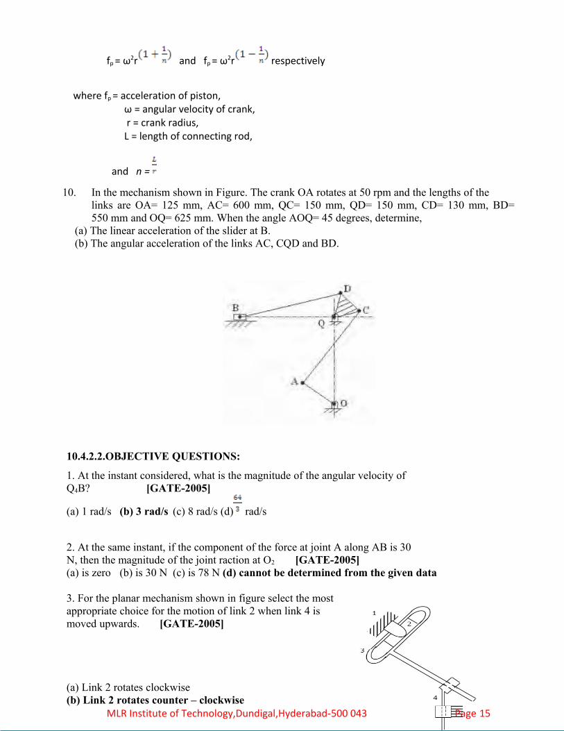
10. In the mechanism shown in Figure. The crank OA rotates at 50 rpm and the lengths of the links are OA= 125 mm, AC= 600 mm, QC= 150 mm, QD= 150 mm, CD= 130 mm, BD= 550 mm and OQ= 625 mm. When the angle AOQ= 45 degrees, determine,
(a) The linear acceleration of the slider at B. (b) The angular acceleration of the links AC, CQD and BD.
10.4.2.2.OBJECTIVE QUESTIONS:
1. At the instant considered, what is the magnitude of the angular velocity ofQ4B? [GATE-2005]
(a) 1 rad/s (b) 3 rad/s (c) 8 rad/s (d) rad/s
2. At the same instant, if the component of the force at joint A along AB is 30N, then the magnitude of the joint raction at O2 [GATE-2005](a) is zero (b) is 30 N (c) is 78 N (d) cannot be determined from the given data
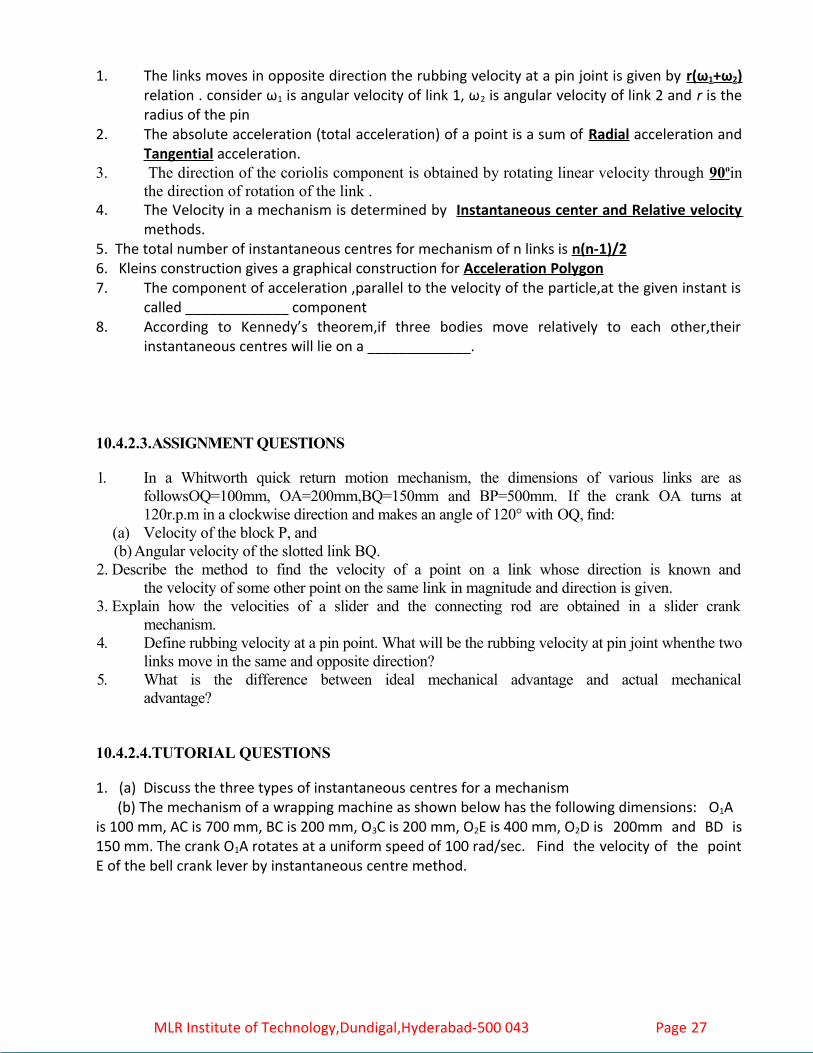
3. For the planar mechanism shown in figure select the most appropriate choice for the motion of link 2 when link 4 is moved upwards. [GATE-2005]
(a) Link 2 rotates clockwise(b) Link 2 rotates counter – clockwise MLR Institute of Technology,Dundigal,Hyderabad-500 043 Page 15

(c) Link 2 does not move(d) Link 2 motion cannot be determined
4. The figure below shows a planar mechanism with single degree of freedom. The instant centre 24 for the given configuration is located at a position [GATE-2004]
(a) L (b)M (c)N (d)∞
5. For the audio cassette mechanism shown in figure given below where is the instantaneous centre of rotation (point) of the two spools? [GATE-2004]
(a) Point P lies to the left of both the spools but at infinity along the line joining A and H(b) Point P lies in between the two spools on the line joining A and H, such that PH=2AP(c) Point P lies to the right of both the spools on the line joining A and H, such that AH=AP(d) Point P lies at the intersection of the line joining B and C and the line joining G and F
6. Instantaneous centre of the body rolling with sliding on a stationary curved surface lies[GATE-2004]
(a) At the point of contact(b) On the common normal at the point of contact (c) On the common tangent at the point of contact (d) At the centre of curvature of the stationary surface
7. In the figure shown, the relative velocity of link 1 with respect to link 2 is 12 m/sec. link 2 rotate at a constant speed of 120 rpm. The magnitude of carioles component of acceleration of link 1 is [GATE-2004]
MLR Institute of Technology,Dundigal,Hyderabad-500 043 Page 16

(a) 302 m/s2 (b)604 m/s2
(c)609 m/s2 (d)1208 m/s2
8. The carioles component of acceleration is present [GATE-2002](a) 4-bar mechanism with 4 turning pairs (b) shaper mechanism(c) slider-crank mechanism (d) Scotch Yoke mechanism
9. Which one of the following statements is correct? [IES-2004] In a petrol engine mechanism the velocity of the piston is maximum when the crank is(a) at the dead centers (b) at right angles to the line of stroke(c) slightly less than 90° to line of stroke (d) slightly above 90° to line of stroke10. A wheel is rolling on a straight level track with a uniform velocity 'v'. The instantaneous velocity of a point on the wheel lying at the mid-point of a radius
[IES-2000](a) varies between 3 v/2 and - v/2 (b) varies between v/2 and - v/2 (c) varies between 3 v/2 and - v/2 (d) does not vary and is equal to v
11. Two points, A and B located along the radius of a wheel, as shown in the figure above, have velocities of 80 and 140 m/s, respectively. The distance between points A and B is 300 mm. The radius of wheel is [IES-2003] (a) 400 mm (b) 500 mm (c) 600 mm (d) 700 mm
12. The crank of the mechanism shown in the side the diagram rotates at a uniform angular velocity θ:
MLR Institute of Technology,Dundigal,Hyderabad-500 043 Page 17

Which one of the following diagrams shows the velocity of slider with respect to the crank angle?
13. In a
slider-crank mechanism, the velocity of piston becomes maximum when(a) Crank and connecting rod are in line with each other [IES-2003](b) Crank is perpendicular to the line of stroke of the piston(c) Crank and connecting rod are mutually perpendicular(d) Crank is 120o with the line of stroke
14. Consider the following statements regarding motions in machines: [IES-2001]1. Tangential acceleration is a function of angular velocity and the radial acceleration is a function of angular acceleration.2. The resultant acceleration of a point A with respect to a point B on a rotating link is perpendicular to AB.3. The direction of the relative velocity of a point A with respect to a point B on a rotating link is perpendicular to AB. Which of these statements is/are correct?(a) 1 alone (b) 2 and 3 (c) 1 and 2 (d) 3 alone
15. Consider a four-bar mechanism shown in the given figure. The driving link DA isrotating uniformly at a speed of 100 r.p.m. clockwise. The velocity of A will be[IES-1999]
(a) 300 cm/s (b) 314 cm/s (c) 325 cm/s (d) 400 cm/s
MLR Institute of Technology,Dundigal,Hyderabad-500 043 Page 18
ANSWER

16. ABCD is a four-bar mechanism in which AD = 30 cm and CD = 45 cm. ADand CD are both perpendicular to fixed link AD, as shown in the figure. Ifvelocity of B at this condition is V, then velocity of C is [IES-1993]
(a) (b) (c) (d)
17. A rod of length 1 m is sliding in a corner as shown in the figure below. At an instant when the rod makes an angle of 0 60 with the horizontal plane, the downward velocity of point A is 1 m/s. What is the angular velocity of the rod at this instant? [IES-2009]
(a) 2.0 rad/s (b) 1.5 rad/s (c) 0.5 rad/s (d) 0.75 rad/s
18. Maximum angular velocity of the connecting rod with a crank to connecting rod ratio 1: for a crank speed of 3000 rpm is around: [IES-2008](a) 300 rad/s (b) 60 rad/s (c) 30 rad/s (d) 3000 rad/s
19. The figure as shown below is a rigid body undergoing planar motion. The absolute tangential accelerations of the points R and S on the body are 150 mm/sec2 and 300 mm/ 2 sec respectively in the directions shown. What is the angular acceleration of the rigid body? [IES-2009](a) 1.66 rad/sec2(b)3.33rad/sec2 (c) 5.00 rad/sec2 (d) 2.50rad/sec
20. ABCD is a bar mechanism, in which AD is the fixed link, and link BC, is in the form of a circular disc with centre P. In which one of the following cases P will be the instantaneous centre of the disc?
[IES-2004]
(a) If it lies on the perpendicular bisector of line BC(b) If it lies on the intersection of the perpendicular bisectors of BC & AD
MLR Institute of Technology,Dundigal,Hyderabad-500 043 Page 19

(c) If it lies on the intersection of the perpendicular bisectors of AB & CD(d) If it lies on the intersection of the extensions of AB and CD
21. The instantaneous centre of rotation of a rigid thin disc rolling without slip on a plane rigid surface is located at [IES-1995, 2002](a) the centre of the disc (b) an infinite distance perpendicular to the plane surface(c) the point of contact (d) the point on the circumference situated vertically opposite to the contact point
22. The relative acceleration of two points which are at variable distance apart on a moving link can be determined by using the [IES-2002](a) three centers in line theorem (b) instantaneous centre of rotation method(C) Corioli’s component of acceleration method (d) Klein's construction
23. In the mechanism ABCD shown in the given figure, the fixed link is denoted as (1), Crank AB as (2), rocker BD as (3), Swivel trunnion at C as (4). The instantaneous centre I41 is at [IES-1996]
(a) the centre of swivel trunnion.(b) the intersection of line AB and a perpendicular to BD to(c) Infinity along AC(d) Infinity perpendicular to BD.
24. The instantaneous centre of motion of a rigid-thin-disc-wheel rolling on plane rigid surface shown in the figure is located at the point. [IES-1996]
(a) A (b) B (c) C (d) D.
25. What is the number of instantaneous centres of rotation for a 6-link mechanism? [IES-2006](a) 4 (b) 6 (c) 12 (d) 15
26. The total number of instantaneous centers for a mechanism consisting of 'n' links is[IES-1998]
MLR Institute of Technology,Dundigal,Hyderabad-500 043 Page 20

(a) (b) (c) (d)
27. A link AB is subjected to a force F ( →) at a point P perpendicular to the link at a distance a from the CG as shown in the figure. This will result in [IES-1999]\
(a) an inertia force F (→) through the CG and no inertia torque(b) all inertia force F.a (clockwise) and no inertia force(c) both inertia force F (→) through the CG and inertia torque Fa (clockwise)(d) both inertia force F (→) through the CG and inertia torque Fa (anti-clockwise)
28. In the diagram given below, the magnitude of absolute angular velocity of link 2 is 10 radians per second while that of link 3 is 6 radians per second. What is the angular velocity of link 3 relative to 2? [IES-2004]
(a) 6 radians per second (b)16radians per second(c) 4 radians per second (d) 14 radians per second
29. When a slider moves with a velocity 'V' on a link rotating at an angular speed of ω, the Corioli's component of acceleration is given by [IES-1998]
(a) (b) (c) (d)
30.
MLR Institute of Technology,Dundigal,Hyderabad-500 043 Page 21

Three positions of the quick-return mechanism are shown above. In which of the cases does the Corioli’s component of acceleration exist? Select the correct answer using the codes given below:
[IES-2003]Codes: (a) 1 only
(b) 1 and 2 (c) 1, 2 and 3 (d) 2 and 3
31. Assertion (A): The direction of Corioli’s acceleration shown in the given figure is correct.Reason (R): The direction of Corioli’s acceleration is such that it will rotate at a velocity v about its origin in the direction opposite to ω.[IES-2000]
(a) Both A and R are individually true and R is the correct explanation of A(b) Both A and R are individually true but R is not the correct explanation of A(c) A is true but R is false(d) A is false but R is true
32. The directions of Coriolis component of acceleration, 2ωV, of the slider A with respect to the coincident point B is shown in figures 1, 2, 3 and 4. Directions shown by figures [IES-1995]
(a) 2 and 4 are
wrong(b) 1 and 2 are wrong(c) 1 and 3 are wrong(d) 2and 3 are wrong.
MLR Institute of Technology,Dundigal,Hyderabad-500 043 Page 22
1 234

33. Consider the following statements: Coriolis component of acceleration depends on[IES-1993]
1. velocity of slider 2. angular velocity of the link 3. acceleration of slider 4. angular acceleration of linkOf these statements(a) 1 and 2 are correct (b) 1 and 3 are correct(c) 2 and 4 are correct (d) 1 and 4 are correct
34. The sense of Coriolis component 2ω is the same as that of the relative velocity vector
rotated. [IES-1992](a) 45° in the direction of rotation of the link containing the path(b) 45° in the direction opposite to the rotation of the link containing the path(c) 90° in the direction of rotation of the link containing the path(d) 180° in the direction opposite to the rotation of the link containing the path
35. What is the direction of the Coriolis component of acceleration in a slotted lever-crank mechanism? [IES 2007](a) Along the sliding velocity vector(b) Along the direction of the crank(c) Along a line rotated 900 from the sliding velocity vector in a direction opposite to the angular velocity of the slotted lever(d) Along a line rotated 900 from the sliding velocity vector in a direction same as that of the angular velocity of the slotted lever
36. The centre of gravity of the coupler link in a 4-bar mechanism would experience [IES-1996] (a) No acceleration (b) only linear acceleration (c) Only angular acceleration(d) both linear and angular accelerations.
37. In the given figure, ABCD is a four-bar mechanism. At the instant shown, AB and CD are vertical and BC is horizontal AB is shorter than CD by 30 cm. AB is rotating at 5 radius and CD is rotating at 2 rad/s. The length of AB is [IES-1994]
(a) 10cm (b) 20 cm
(c) 30 cm (d) 50 cm.
38. In a single slider four-bar linkage, when the slider is fixed, it forms amechanism of [IES-1999]
MLR Institute of Technology,Dundigal,Hyderabad-500 043 Page 23

(a) hand pump (b) reciprocating engine(c) quick return (d) oscillating cylinder
39. A four-bar mechanism ABCD is shown in the given figure. If the linear velocity'VB' of the point 'B' is 0.5 m/s, then the linear velocity 'Vc’ of point 'c' will be [IAS-1999](a) 1.25 m/s(b) 0.5 m/s(c) 0.4 m/s(d) 0.2 m/s
40. How many instantaneous centers of rotation are there for the mechanism shown in the figure given above? [IAS-2007](a) 6(b) 10(c) 15(d) 21
41. What is the number of instantaneous centers for an eight link mechanism?
[IAS-2004](a) 15 (b) 28 (c) 30 (d)8
42. The given figure shows a slider crank mechanism in which link 1is fixed. The number of instantaneous centers would be [IAS-1998]
(a) 4 (b) 5 (c) 6 (d)12
43. Consider the following statements: [IAS-2007]1. Corioli’s component of acceleration is a component of translatory acceleration.2. If the relative motion between two links of a mechanism is pure sliding, then the relative instantaneous centre for these- two links does not exist.Which of the statements given above is/are correct?
MLR Institute of Technology,Dundigal,Hyderabad-500 043 Page 24

(a) 1 only (b) 2 only (c) Both 1 and 2 (d) Neither 1 nor 2
44. Consider the following statements:Corioli’s acceleration component appears in the acceleration analysis ofthe following planar mechanisms: [IAS-2003]1. Whitworth quick-return mechanism. 2. Slider-crank mechanism.2. Scotch-Yoke mechanism.Which of these statements is/are correct?(a) 1, 2 and 3 (b) 1and 2 (c) 2 and 3 (d) 1 only45. The above figure shows a four bar mechanism. If the radial acceleration of the point C is 5 cm/s2, the length of the link CD is [IAS-2002](a) 2 cm(b) 10 cm(c) 20 cm(d) 100 cm
46. A slider sliding at 10 cm/s on a link which is rotating at 60 r.p.m. is subjected to Corioli’s acceleration of magnitude [IAS-2002]
(a) 40 2 cm / s2 (b) 0.4 cm / s2 (c) 40 cm / s2 (d) 4 cm/ s2
47. A body in motion will be subjected to Corioli's acceleration when that body is [IAS 1994]
(a) in plane rotation with variable velocity(b) in plane translation with variable velocity(c) in plane motion which is a resultant of plane translation and rotation(d) restrained to rotate while sliding over another body
48. The given figure shows the Klein's construction for acceleration of the slider-crank mechanism Which one of the following quadrilaterals represents the required acceleration diagram? [IES-2001]
(a) ORST (b) OPST (c) ORWT (d) ORPT
49. The Klein's method of construction for reciprocating engine mechanism. [IES-1994](a) is a simplified version of instantaneous centre method (b) utilizes a quadrilateral similar to the diagram of mechanism for reciprocatingEngine (c) enables determination of Corioli' s component. (d) is based on the acceleration diagram.
MLR Institute of Technology,Dundigal,Hyderabad-500 043 Page 25

50. Figure shows Klein's construction for slider-crank mechanism OCP drawn to full scale. What velocity does CD represent? [IES-2003]
(a) Velocity of the crank pin (b) Velocity of the piston (c) Velocity of the piston with respect to crank pin (d) Angular velocity of the connecting Rod 51. Klein's construction for determining the acceleration of piston P is shown in the given figure. [IES-1995]
When N coincides with K(a) acceleration of piston is zero and its velocity is zero. (b) acceleration is maximum and velocity is maximum. (c) acceleration is maximum and velocity is zero (d) acceleration is zero and velocity is maximum.
CHOOSE THE CORRECT ALTERNATIVE (JNTU HYDERABAD )
1. The total number of instantaneous centers for a mechanism consisting of n links are [D ] (A) n/2 (B) n (C)(n-1)/2 (D) n(n-1)/2
2. The instantaneous centers which vary with the configuration of the mechanism are Called [C ] (A) Permanent instantaneous centers (B) fixed instantaneous centers (C) Neither fixed nor permanent instantaneous centers (D) none of these
3. Corioli’s components is encountered in [A ] (a)Quick return mechanism of shaper (b) four bar chain mechanism (c) Slider crank mechanism (d) all of the above
4. The coriolis component of acceleration is taken into account for [ C] (A)Slider crank mechanism (B) Four bar mechanism (C)Quick return motion mechanism (D) None of these
5. The component of acceleration, parallel to the velocity of the particle at the given Instant is called [ B] A) Radial component (B) tangential component B)Coriolis component (D) None of the above
FILL IN THE BLANKS
MLR Institute of Technology,Dundigal,Hyderabad-500 043 Page 26
1. The links moves in opposite direction the rubbing velocity at a pin joint is given by r(ω1+ω 2) relation . consider ω1 is angular velocity of link 1, ω2 is angular velocity of link 2 and r is the radius of the pin
2. The absolute acceleration (total acceleration) of a point is a sum of Radial acceleration and Tangential acceleration.
3. The direction of the coriolis component is obtained by rotating linear velocity through 90 o in the direction of rotation of the link .
4. The Velocity in a mechanism is determined by Instantaneous center and Relative velocity methods.
5. The total number of instantaneous centres for mechanism of n links is n(n-1)/26. Kleins construction gives a graphical construction for Acceleration Polygon7. The component of acceleration ,parallel to the velocity of the particle,at the given instant is
called _____________ component 8. According to Kennedy’s theorem,if three bodies move relatively to each other,their
instantaneous centres will lie on a _____________.
10.4.2.3.ASSIGNMENT QUESTIONS
1. In a Whitworth quick return motion mechanism, the dimensions of various links are as followsOQ=100mm, OA=200mm,BQ=150mm and BP=500mm. If the crank OA turns at 120r.p.m in a clockwise direction and makes an angle of 120° with OQ, find:
(a) Velocity of the block P, and(b) Angular velocity of the slotted link BQ.
2. Describe the method to find the velocity of a point on a link whose direction is known andthe velocity of some other point on the same link in magnitude and direction is given.
3. Explain how the velocities of a slider and the connecting rod are obtained in a slider crankmechanism.
4. Define rubbing velocity at a pin point. What will be the rubbing velocity at pin joint whenthe two links move in the same and opposite direction?
5. What is the difference between ideal mechanical advantage and actual mechanicaladvantage?
10.4.2.4.TUTORIAL QUESTIONS
1. (a) Discuss the three types of instantaneous centres for a mechanism (b) The mechanism of a wrapping machine as shown below has the following dimensions: O1A is 100 mm, AC is 700 mm, BC is 200 mm, O3C is 200 mm, O2E is 400 mm, O2D is 200mm and BD is 150 mm. The crank O1A rotates at a uniform speed of 100 rad/sec. Find the velocity of the point E of the bell crank lever by instantaneous centre method.
MLR Institute of Technology,Dundigal,Hyderabad-500 043 Page 27

2. (a) State and Explain Kennedy's theorem as applicable to instantaneous center of rotation of three bodies. (b) In the mechanism shown in Figure. the crank OA makes 400 r.p.m in the counter clockwise direction. Find
i). angular velocity of the link BA andii). velocity of the slider at A. The lengths of the links are OA= 60mm, OB= 220 mm and BC= 300mm.
3. A Four bar mechanism has the following dimensions: AB = 300 mm, BC = CD = 600 mm: AD = 700 mm. The link AD is fixed and the angle BAD is 45o. The driving link AB rotates uniformly at a speed of 500 r.p.m clockwise. Find the angular velocity and angular acceleration of the output link CD.4. A crank and rocker mechanism ABCD has the following dimensions: AB =0.75 m, BC =1.25
m, CD =1 m, AD =1.5 m and CF = 500 mm. AD is the fixed link. F lies on BC produced. Crank AB has an angular velocity of 30 rad/s counter clock-wise and a deceleration of 200 rad/s2 at the instant angle DAB= 300. Find
(a) The instantaneous linear acceleration of C and F and (b) The instantaneous angular velocities and accelerations of links BC and CD.5. Figure shows the quick-return mechanism of the Slotted lever type, the various dimensions of
which are, OA= 400 mm, OP= 200mm, AR= 600mm, RS= 300 mm.For the configuration when the angle AOP=120o, determine the acceleration of the cutting Tool at S and the angular acceleration of the link RS. The crank OP rotates at 210 rpm.
10.4.2.5. NPTEL LINK
MLR Institute of Technology,Dundigal,Hyderabad-500 043 Page 28

http://www.nptel.ac.in/video.php/subject id = 11210421/9http://www.nptel.ac.in/video.php/subject id = 11210421/10http://www.nptel.ac.in/video.php/subject id = 11210421/11http://www.nptel.ac.in/video.php/subject id = 11210421/12http://www.nptel.ac.in/video.php/subject id = 11210421/13http://www.nptel.ac.in/video.php/subject id = 11210421/14
10.4.3.6.SUBJECTIVE QUESTIONS
1. Show that for Tchebicheff's straight-line motion shown in figure. the point P that bisects the link BC will lie in a straight line parallel to AD. When it is directly above the midpoint of AD, if the proportions of the links are BC: AD: AB = 1:2:2.5.
2. In grasshopper straight-line motion mechanism figure the point `P' traces an approximate vertical straight-line motion as the crank OA rotates. The lengths of the links PQ =24cm, vertical link O1Q=24cm and QA= 6cm. Determine the length of the crank OA. Also find the maximum deviation of P from the vertical straight line in a travel of 6cm on each side if its mean position.
3. In the figure shown OA and AC are the crank and connecting rod respectively. B is a point lying on the extension of AC. Find the length of the crank in order that the point B traverses approximately along a straight line when the connecting rod rotates from angle θ1 to angle θ2.
MLR Institute of Technology,Dundigal,Hyderabad-500 043 Page 29

4. Prove that the tracing point, giving the horizontal straight-line motion in Tchebicheff's mechanism, lies at the mid point of the coupler.
5. (a) Prove that the tracing point, giving the horizontal straight line motion in Tchebicheff mechanism, lies at the mid point of the coupler.
(b) Prove that a point on one of links of a Hart mechanism traces a straight line on the movement of its links?
6. (a) Under what conditions Scott-Russel mechanism traces out a straight line and an ellipse? State the limitations of Scott-Russel mechanism.
(b) Sketch a pantograph, explain its working and show that it can be used to reproduce to an enlarged scale a given figure.
7. A circle has OR as its diameter and a point Q lies on its circumference. Another point P lies on the line OQ produced. If OQ turns about O as centre and the product OQ x OP remains constant, show that the point P moves along a straight line perpendicular to the diameter OR.
8. (a) Sketch a Paucellier mechanism. Show that it can be used to trace a straight line. (b) How can you show that a Watt mechanism traces an approximate straight line?
9. A torque of 85 N-m is applied to the link OA at A of a Gross-Hopper mechanism shown in figure. The link OA makes an angle of 18 degrees with the horizontal. Find the magnitude of the vertical force exerted at B to overcome the resisting torque of 85 N-m. The lengths of the links are: OA=30 mm, AC= 50 mm and CB= 130 mm. If the link OA makes an angle of 10 and zero degrees with the horizontal, what will be the vertical force at B to overcome the torque of 85 Nm?
10. In the grasshopper mechanism shown in figure, if AQ2 =AP.OA, determine the vertical force at P necessary to resist a Torque T applied to the crank OA.
MLR Institute of Technology,Dundigal,Hyderabad-500 043 Page 30

11. (a) Explain Davis steering gear with a neat sketch. (b) For a Davis steering gear, derive the expression for the angle of inclination of the track arms to longitudinal axis of the vehicle in terms of the distance between the pivots of the front axle and wheelbase. (c) In a Davis steering gear the distance between the pivots of the front axle is 90 cm and the
wheelbase is 220 cm. When the vehicle is moving along a straight path, find the inclination of the track arms to the longitudinal axis of the vehicle.
12. The distance between the pivots of the front stub axles of a car is 130 cm, the length of track rod is 120 cm, the wheel track is 145 cm and the wheelbase is 280cm. What should be the length of track arm if the Ackermann steering gear is to be given a correct steering, when rounding a corner of 6-meter radius?
13. (a) What condition must be satisfied by the steering gear of a car in order that the wheels may have a pure rolling motion when rounding a curve? Deduce the relationship between the inclinations of the front stub axles to the rear axle, the distance between the pivot centers for the front axles and the wheelbase of the car. (b) What is a Hooke's joint? Show that for a Hooke's joint tan θ = cos α tan , where θ and ϕ are the angles turned by the driving and driven shafts at any instant and α is the angle of inclination of driven shaft with driving shaft.
14. (a) For an Ackermann steering gear, derive the expression for the angle of inclination of the track arms to longitudinal axis of the vehicle.
(b) A Hooke's joint connects two shafts whose axes intersect at 1500. The driving shaft rotates uniformly at 120rpm. The driven shaft operates against a steady torque of 150 Nm and carries a flywheel whose mass is 45 Kg and radius of gyration 150mm. Find the
maximum torque which will be exerted by the driving shaft.
15. (a) An Ackermann steering gear does not satisfy the fundamental equation of steering gear at all positions. Yet it is widely used. Why?
(b) Two shafts are to be connected by a Hooke’s joint. The driving shaft rotates at a uniform speed of 500 rpm and the speed of the driven shaft must lie between 475 and 525 rpm. Determine
the maximum permissible angle between the shafts.
16. (a) What conditions must be satisfied by the steering mechanism of a car in order that the wheels may have a pure rolling motion when rounding a curve? Deduce the relationship connecting the inclinations of the front stub axles to the rear axle, the distance between the pivot centres for the front axles and wheel base of the car.
MLR Institute of Technology,Dundigal,Hyderabad-500 043 Page 31

(b) Give salient features of the speed of driven shaft of a Hooke’s joint by drawing a polar diagram.
17. (a) Derive an expression for the ratio of angular velocities of the shafts of a Hooke’s joint. (b) Using Davis steering gear, find the inclination of the track arms to the longitudinal axis of the car if the length of car between axles is 2.3 m, and the steering pivots are 1.3 m apart. The car is moving in a straight path.
18. (a) What is the condition for correct steering? Sketch and show the two main types of steering gears and discuss their relative advantages.
(b) A double universal joint is used to connect two shafts in the same plane. The intermediate shaft is inclined at an angle of 20o to the driving shaft as well as the driven shaft. Find the maximum and minimum speed of the intermediate shaft and the driven shaft if the driving shaft has a constant speed of 500 rpm
19. (a) Derive the condition for correct steering. If the correct steering condition is not satisfied, then what happens?
(b) In a Hooke's joint the driving shaft rotates uniformly and the total variation in the speed of the driven shaft is not to exceed 10 % of the mean speed. What is the greatest possible inclination of the centre lines of the shaft.
20. (a) What is the condition for the correct steering? Sketch the two main types of steering gears and discuss their relative advantages. (b) A Hooke's joint connects two shafts, which are having 150 degrees as the included angle.
The driving shaft rotates uniformly at 1200 rpm. Find the maximum acceleration of the driven shaft and the maximum torque required if the driven shaft carries a flywheel of mass 10 kg and 90 mm radius of gyration.
10.4.3.7.OBJECTIVE QUESTIONS:
1. The coupling used to connect two shafts with large angular misalignment is [GATE-2002](a) a Flange coupling (b) an Oldham's coupling (c) a Flexible bush coupling (d) a Hooker’s joint2. Assertion (A): The Ackermann steering gear is commonly used in all automobiles. [IES-1996]Reason (R): It has the correct inner turning angle for all positions.(a) Both A and R are individually true and R is the correct explanation of A(b) Both A and R are individually true but R is not the correct explanation of A(c) A is true but R is false(d) A is false but R is true3. Match List-I with List-II and select the correct answer using the codesgiven below the Lists.(Notations have their usual meanings) : [IES-2001]List I List IIA. Law of correct steering 1. f = 3(n-1)-2 j
B. Displacement relation of 2.
Hook’s joint
C. Relation between kinematic 3.
pairs and links
MLR Institute of Technology,Dundigal,Hyderabad-500 043 Page 32

D. Displacement equation of 4.
reciprocating engine pistonCodes: A B C D A B C D (a) 1 4 3 2 (b) 1 2 3 4 (c) 3 4 1 2 (d) 3 2 1 4
4. A motor car has wheel base of 280 cm and the pivot distance of front stub axles is 140 cm. When the outer wheel has turned through 30°, the angle of turn of the inner front wheel for correct steering will be [IES-2001]
(a) 60° (b) (c) (d) 30o
5. Givenθ= angle through which the axis of the outer forward wheel turnsϕ = angle through which the axis of the inner forward wheel turns a = distance between the pivots of front axle and b = wheel base. For correct steering, centre lines of the axes of four wheels of an automobile should meet at a common point. This condition will be satisfied if [IES-2001]
(a) (b)
(c) (d)
6. In automobiles, Hook's joint is used between which of the following? [IES-2008](a) Clutch and gear box(b) Gear box and differential(c) Differential and wheels(d) Flywheel and clutch
7. Which one of the following statements is not correct? [IES-2006](a) Hooke's joint is used to connect two rotating co-planar, non-intersecting shafts(b) Hooke's joint is used to connect two rotating co-planar, intersecting shafts(c) Oldham's coupling is used to connect two parallel rotating shafts(d) Hooke's joint is used in the steering mechanism for automobiles
8. A Hook’s Joint is used to connect two: [IES-2005](a) Coplanar and non-parallel shafts (b) Non-coplanar and non-parallel shafts(c) Coplanar and parallel shafts (d) Non-coplanar and parallel shafts
9. The speed of driving shaft of a Hooke's joint of angle 19.5° (given sin 19.5o =0.33. cos 19.5° = 0.94) is 500 r.p.m. The maximum speed of the driven shaft is nearly [IES-2001](a) 168 r.p.m. (b) 444 r.p.m. (c) 471 r.p.m. (d) 531 r.p.m.
10. Match List I (Applications) with List II (Joints) and select the correct answer using the codes given below the Lists: [IES-2000]
List I List IIA. Roof girder 1. Hook's jointB. Cylinder head of an IC engine 2. Screwed jointC. Piston rod and cross head 3. Cotter jointD. Solid shaft and a plate 4. Welded joint
5. Riveted jointCodes: A B C D A B C D (a) 5 3 1 4 (b) 4 2 3 1
MLR Institute of Technology,Dundigal,Hyderabad-500 043 Page 33

(c) 5 2 3 4 (d) 4 3 1 5
11. Which one of the following figures representing Hooke's jointed inclined shaft system will result in a velocity ratio of unity? [IES-1998]
12. Consider the following statements [IAS 1994]1. A round bar in a round hole form a turning pair.2. A square bar in a square hole forms a sliding pair.3. A vertical shaft in a footstep bearing forms a successful constraint.Of these statements(a) 1 and 2 are correct (b) 1 and 3 are correct(c) 2 and 3 are correct (d) 1, 2 and 3 are correct
13. The connection between the piston and cylinder in a reciprocating engine corresponding to [IAS 1994]
(a) completely constrained kinematic pair (b) incompletely constrained kinematic pair(c) successfully constrained kinematic pair (d) single link
14. The type of quick return mechanism employed mostly in shaping machines is: [IES-1997]
(a) DC reversible motor (b) Fast and loose pulleys (c) Whitworth motion (d) Slotted link mechanism
15. In order to draw the acceleration diagram, it is necessary to determine the Corioli’s component of acceleration in the case of `````` [IES-1997](a) crank and slotted lever quick return mechanism(b) slider-crank mechanism (c) four bar mechanism (d) pantograph
16. Which mechanism produces intermittent rotary motion from continuous rotary motion? [IES-2008]
(a) Whitworth mechanism (b) Scotch Yoke mechanism(c) Geneva mechanism (d) Elliptical trammel
MLR Institute of Technology,Dundigal,Hyderabad-500 043 Page 34
ANSWER

17. ABCD is a mechanism with link lengths AB = 200, BC = 300, CD = 400 and DA = 350. Which one of the following links should be fixed for the resulting mechanism to be a double crank mechanism? (All lengths are in mm)``` [IES-2004]
(a) A B (b) BC (c) CD (d) DA
18. A point on a link connecting a double slider crank chain will trace a [IES-2000](a) straight line (b) circle (c) parabola (d) ellipse19. Match List-I with List -II and select the correct answer using the codes given below the List
[IAS-1997]List – I List-II
A.Pantograph 1. Scotch yoke mechanismB. Single slider crank chain 2. Double lever mechanismC. Double slider crank chain 3. Tchebicheff mechanismD. Straight line motion 4. Double crank mechanism
5. Hand pump
Codes: A B C D A B C D (a) 4 3 5 1 (b) 2 5 1 3 (c) 2 1 5 3 (d) 4 5 2 1
20. Consider the following mechanisms: [IAS-2002]1. Oscillating cylinder engine mechanism2. Toggle mechanism3. Radial cylinder engine mechanism4. Quick Return MechanismWhich of the above are inversions of Slider-crank mechanism?(a) 1, 2 and 4 (b) 2, 3 and 4 (c) 1, 2 and 3 (d) 1, 3 and 4
21. Geneva mechanism is used to transfer components from one station to the other in [IAS-1996](a) an inline transfer machine (b) a rotary transfer machine(c) a linked line (d) an unlinked flow line
22. Match List I (Mechanism) with List II (Name) and select the correct answer using the codes given below the Lists: [IAS-2002]List I (Mechanism) List II(Name)A. Mechanism used to reproduce a 1.Hart's mechanismdiagram to an enlarged or reduced scaleB. A straight line mechanism made 2. Pantograph up of turning pairsC. Approximate straight line motion 3. Grasshopper mechanismconsisting of one sliding pairD. Exact straight line motion mechanism 4. Peaucellier's mechanismCodes: A B C D A B C D
MLR Institute of Technology,Dundigal,Hyderabad-500 043 Page 35

(a) 3 1 2 4 (b) 2 1 3 4 (c) 3 4 2 1 (d) 2 4 3 1
23. Which one of the following is an exact straight line mechanism using lower pairs? [IAS-2003](a) Watt's mechanism (b) Grasshopper mechanism(c) Robert's mechanism (d) Paucellier’s mechanism
24. Assertion (A): Davis steering gear is preferred to Ackermann type in automobileapplications. [IAS-2001]Reason (R): Davis steering gear consists of sliding pairs as well as turning pairs.(a) Both A and R are individually true and R is the correct explanation of A (b) Both A and R are individually true but R is not the correct explanation of A(c) A is true but R is false(d) A is false but R is true
CHOOSE THE CORRECT ALTERNATIVE ( JNTU HYDERABAD)
1. An exact straight line motion mechanism is a.... [ D] (A) Scott Russel’s mechanism (A) Hart’s mechanism (C) peaucellier’s mechanism (D) All of these
2. Which of the following mechanism is made up of turning pair? [D] (A)Scott Russel’s mechanism (B) peaucellier’s mechanism (C) Hart’s mechanism (D) b &c
3. Which of the following mechanism is exactly straight line motion mechanism [ A] (A)Peaucellier Mechanism (B)Robert Mechanism
(C)Tchebicheff’s Mechanism (D) Watt’s Mechanism
4. Scott-Russel Mechanism consists of [ A] (A) Sliding & Turning pairs (B) Sliding & Rotary pairs (C) Turning & Rotary pairs (D) Sliding only
5. Which of the following mechanism is generated straight line motion mechanism [ C] (A)Peaucellier Mechanism (B)Scott- Russel Mechanism (C) Robert Mechanism (D) Watt’s Mechanism
6. The magnitude of linear velocity of a point Q on link PQ relative to point P is [ B] (A) ω.PQ (B) ω.(PQ)2 (C) ω2.PQ (D) (ω.PQ)2
7. The Ackerman steering gear mechanism is preferred to the Davis steering gear Mechanism, because [ D]
(A)Whole of the mechanism in the Ackerman steering gear is on the back of the front wheels. (B) The Ackerman steering gear consists of turning pairs (C) The Ackerman steering gear is most economical (D) Both (a) and (b)
MLR Institute of Technology,Dundigal,Hyderabad-500 043 Page 36

8. With single Hooke’s joint it is possible to connect two shafts, the axes of which have an angular misalignment up to [D ] (A)100 (B) 200 (C) 300 (D) 400
9. In which mechanism, the coriolis component of acceleration will be considered [B ] (A)Four-bar chain mechanism (B) Quick return motion mechanism (C) Slider-crank mechanism (D) none of the above
10. The driving and driven shaft connected by Hook’s joint will have equal speeds if θ=angle through which the driving shaft turns, α=angle of inclination of driving and driven shaft then [ B] (A) cosθ=sinα (B) sinθ= √tanα (C) tanθ=√cosα (D) cotθ=cosα
11. The magnitude of linear velocity of a point Q on link PQ relative to point P is [ C] (A) ω.PQ (B) ω.(PQ)2 (C) ω2.PQ (D) (ω.PQ)2
FILL IN THE BLANKS (JNTU HYDERABAD)1. A Peaucellier mechanism consist of 08 (Eight) number of links2. Grass hopper mechanism can be obtained by replacingslidingpair of modified scott russel
mechanism by turningpair 3. Hart mechanism has 6links4. The motion which permits only relative motion of an oscillatory nature along a straight line
is called straight line mechanism 5. The two types of mechanisms are in which only turning pairs are used and in which one sliding
pair is used6. The number of links required for the Peauciller mechanism is 87. The number of links required for the Hart's mechanism is 6 8. The disadvantage of Hart's mechanism is large amount of space is taken 9. The applications of straight line motions are mostly found in engine indicators 10. The modified form of the pantograph copying mechanism is cross-by indicator 11. The one which is closely resembles to the pantograph copying mechanism is simplex indicator 12. Roberts's mechanism is a four bar chain mechanism, which in its mean position has the
form of a trapezium.13. Tchebicheff s mechanism is a four bar mechanism in which the crossed links are of equal
length.14. Grasshopper mechanism is a modification of modified Scott-Russel's mechanism15. UniversalorHook’sJoint is used to connect two non-parallel and intersecting shafts.16. Davis Steering gear mechanism satisfies the fundamental equation of gearing in all
position.17. Davis steering gear consists ofslidingpair18. In automobiles the power is transmitted from gear box to differential throughHook’sJoint19. The steering gear mechanism is used for changing the direction of two or more of the wheel
axiswith reference to the chassis20. In which type of mechanism steering is done by means of front wheels steering gear 21. In order to avoid skidding slipping of the wheels the two front wheels must turn about the
which lies on the axis of the back wheels same instantaneous 22. The condition for correct steering is that all the four wheels must turn about the same instantaneous centre 23. The fundamental equation for the correct steering is given by (cot0-cot6=c/b) 24. Davis steering gear is an exact steering mechanism. MLR Institute of Technology,Dundigal,Hyderabad-500 043 Page 37

25. Which of the steering gear mechanisms is simpler? Ackerman26. A (Hooke's joint) is used to connect two shafts, which are intersecting at a small angle.27.The arms of the cross in the universal joint are perpendicular to each other.28. The main application of universal joint is found in the transmission from the gear box to
theof the automobile. Differential 29. Universal joint is used as a knee joint in milling machines. 30. Double hooke's joint type of joint has the constant velocity. 31. The maximum fluctuation of speed is given by (col(max)=o>/cosa)32.In a pantograph, all the pairs are turning pairs 33. Which of the following mechanism is made up of turning pairs peaucellier's mechanism 34. Which of the following mechanism is used to enlarge or reduce the size of a drawing
pantograph 35.The Ackerman steering gear mechanism is preferred to the Davis steering gear mechanism,because the Ackerman steering gear is most economical 36.The driving and driven shafts connected by Hooke's joint will have equal speeds, if (tan6=+Vcosa)
10.4.3.8.ASSIGNMENT QUESTIONS
1. What are straight line mechanisms? Describe one type of exact straight line motion mechanism2. Describe the Watt's parallel mechanism for straight line motion and derive the condition under
which the straight line is traced.3. Sketch an intermittent motion mechanism and explain its practical applications.4. Explain Hooke's joint or Universal joint?5. Two shafts are connected by a universal joint. The driving shaft rotates at a uniform speedof 1500
r.p.m. Determine the greatest permissible angle between the shaft axes so that the totalfluctuation of speed does not exceed 200 r.p.m. Also calculate the maximum and minimum speeds of the driven shafts.
6. In a Hooke's joint, the angle between the two shafts is 15o. Find the angles turned by the driving shaft when the velocity of driven shaft is maximum, minimum and equal to that of the driving shaft. Also Determine when the driven shaft will have the maximum acceleration and reatrdation.
7. In a Davis steering gear, the length of the car between axles is 2.4 m, and the steerin pivots are 1.35 m apart. Determine the inclination of the track arms of the longitudianal axis of the car when the car moves in a straight path.
8. The two shaftsof a Hooke's coupling have their axes inclined at 20o. The shaft A revolves at a uniform speed of 1000 rpm. The shaft B carries a flywheel of mass 30 kg. If the radius of gyration of the flywheel is 100 mm, find the maximum torque in shaft B.
10.4.3.9.TUTORIAL QUESTIONS
1. The distance between the fixed centres O and Ol of a Watt's straight line motion, is250mm. The lengths of the three moving links OB,BA and AO1 are 150mm, 75mm and100mm respectively. Find the position of a point P and BA which gives the best straight linemotion.
2. The angle between the axes of two shafts connected by a Hooke's joint is 22.5 degrees. The power supplied to the driving shaft is 7.5 KW at a uniform speed of 300 rpm. If the output torque on the driven shaft is not to vary by more than 15 percent of the input torque, what is the necessary moment of inertia of the flywheel?
MLR Institute of Technology,Dundigal,Hyderabad-500 043 Page 38

3. Two inclined shafts are connected by means of a universal joint. The speed of the driving shaft is 1000 rpm. If the total fluctuation of speed of driven shaft is not to exceed 12.5% of this, what is the maximum possible inclination between the two shafts? With this angle, what will be the maximum acceleration to which the driven shaft is subjected and when this will occur?
4. A double universal joint is used to connect two shafts in the same plane. The intermediateshaft is inclined at an angle of 20° to the driving shaft as well as the driven shaft. Find themaximum and minimum speed of the intermediate shaft and the driven shaft if the driving shafthas a constant speed of 500 r.p.m.
5. Two shafts with an included angle of 160° are connected by a Hooke's joint. The drivingshaft runs at a uniform sped of 1500 r.p.m. The driven shaft carries a flywheel of mass 12kgand 100mm radius of gyration. Find the maximum angular acceleration of the driven shaft andthe maximum torque required.
6. Two shafts are connected by a Hooke's joint. The driving shaft revolves uniformly at 500 r.p.m. If the total permissible variation in speed of the driven shaft is not to exceed ±_6% of the mean speed, find the greatest permissible angle between the centre lines of the shafts.
10.4.3.10. NPTEL LINK
http://www.nptel.ac.in/video.php/subject id = 11210421/
10.4.4.1.SUBJECTIVE QUESTIONS 1. (a) What is cam? What is displacement diagram with reference to cam? (b) The following data relate to a cam profile in which the follower moves with uniform
acceleration and deceleration during ascent and descent.Minimum radius of cam = 25 mm, Roller diameter = 7.5 mm, Lift = 28 mm, Offset of follower
axis = 12 mm towards right, Angle of ascent = 600, Angle of descent = 900, Angle of dwell between ascent and descent = 450, Speed of the cam = 200 rpm.
Draw the profile of the cam and determine the maximum velocity and the uniform acceleration of the follower during the outstroke and the return stroke.
2. (a) What is the importance of pressure angle of a cam? (b) A cam is to operate a flat-faced follower having uniform acceleration and deceleration during
ascent and descent. The least radius of the cam is 50mm. During descent, the deceleration period is half of the acceleration period. The ascent lift is 37.5mm. The ascent is for 1/4th period, dwell for 1/4th, descent for 1/3rd, and dwell for the remaining 1/6 the period. The cam rotates 600 rpm. Find the maximum velocity and acceleration during ascent and descent.
3. A tangent cam with a base circle diameter of 50mm operates a roller follower 20mm in diameter. The line of stroke of the roller follower passes through the axis of the cam. The angle between the tangential faces of the cam is 600, speed of the cam shaft 200 rpm and the lift of the follower 15mm. Calculate,
(a) The main dimensions of the cam.(b) The acceleration of the follower at
i. The beginning of lift.
MLR Institute of Technology,Dundigal,Hyderabad-500 043 Page 39

ii.Where the roller just touches the nose. i.e. the apex of the circular nose.
4. The following data relate to a cam operating an oscillating roller follower:Minimum radius of cam = 44mm. Diameter of roller = 14mm, Length of the follower arm =
40mm. Distance of fulcrum centre from cam centre = 50mm, Angle of ascent = 75o, Angle of descent = 105o, Angle of dwell for follower in the highest position = 60o, Angle of oscillation of follower = 28o. Draw the profile of the cam if the ascent and descent both take place with SHM.5. (a) Explain the procedure to layout the cam profile for a reciprocating follower. (b) Derive relations for velocity and acceleration for a convex cam with a flat faced follower.
6. Draw a cam profile which would impart motion to a flat faced follower in the following desired way. The stroke of the follower being 5 cm. i) The follower to move with uniform acceleration upward for 90o, dwell for next 90o. ii) The follower to return downward with uniform retardation for 120o and dwell for next 60o.
The minimum radius of the cam being 3 cm.
7. (a) Compare the performance of Knife –edge, roller and mushroom followers. (b) A knife edged follower for the fuel valve of a four stroke diesel engine has its centre line
coincident with the vertical centre line of the cam. It rises 2.5 cm with SHM during 60o
rotation of cam, then dwells for 20o rotation of cam and finally descends with uniform acceleration and deceleration during 45o rotation of cam, the deceleration period being half the acceleration period. The least radius of the cam is 5 cm. Draw the profile of the cam to full size.
8. (a) How can cams be classified according to motions of the followers. (b) Set out the profile of a cam to give the following motion to a at mushroom contact face follower:
Follower to rise through 24 mm during 150o of cam rotation with SHM.Follower to dwell for 30o of the cam rotation.Follower to return to the initial position during 90o of the cam rotation with SHM.Follower to dwell for the remaining 90o of cam rotation. Take minimum radius of the cam as 30 mm.
9. (a) What is a displacement diagram? Why is it necessary to draw it before drawing a cam profile?
(b) Draw the profile of a cam operating a knife edge follower having a lift of 30 mm. The cam raises the follower with SHM for 150o of the rotation followed by a period of dwell for 60o.
The follower descends for the next 100o rotation of the cam with uniform velocity, again followed by a dwell period. The cam rotates at a uniform velocity of 120 rpm and has a least radius of 20 mm. What will be the maximum velocity and acceleration of the follower during the lift and the return?
10. Draw the displacement, velocity and acceleration diagrams for a follower when it moveswith simple harmonic motion. Derive the expression for velocity and acceleration duringoutstroke and return stroke of the follower.
10.4.4.2.OBJECTIVE QUESTIONS
1. In a plate cam mechanism with reciprocating roller follower, the followerhas a constant acceleration in the case of [GATE-1993]
MLR Institute of Technology,Dundigal,Hyderabad-500 043 Page 40
(a) Cycloidal motion(b) Simple harmonic motion(c) Parabolic motion(d) 3-4-5 polynomial motion Ans. (c)For uniform acceleration and retardation, the velocity of the follower must changeat a constant rate and hence the velocity diagram of the follower consists of slopingstraight lines. The velocity diagram represents everywhere the slope of thedisplacement diagram, the later must be a curve whose slope changes at a constantrate. Hence the displacement diagram consists of double parabola.Pressure angle2. For a spring-loaded roller-follower driven with a disc cam, [GATE-2001](a) The pressure angle should be larger during rise than that during return for easeof transmitting motion.(b) The pressure angle should be smaller during rise than that during return forease of transmitting motion.(c) The pressure angle should be large during rise as well as during return for easeof transmitting motion.(d) The pressure angle does not affect the ease of transmitting motion. Ans. (c)
3. The profile of a cam in a particular zone is given by x = 3 cos� and y =sin�. The normal to the cam profile at � �� / 4 is at an angle (with respect to x axis) [GATE-1998]a). π /4 b) π /2 c) π /3 d) 0
Ans. (c)
4. In a cam-follower mechanism, the follower needs to rise through 20 mmduring 60o of cam rotation, the first 30o with a constant acceleration andthen with a deceleration of the same magnitude. The initial and finalspeeds of the follower are zero. The cam rotates at a uniform speed of 300rpm. The maximum speed of the follower is [GATE-2005](a) 0.60m/s (b) 1.20m/s (c) 1.68m/s (d) 2.40m/sAns. (d)
CHOOSE THE CORRECT ALTERNATIVE ( JNTU HYDERABAD )
1. For the knife edge follower, the cam profile and pitch curve [ B] A) are different B)are same C)may be same or different D)none of the above
2. The angle, which represents the cam profile and is most important in cam design, is [B ] A) Cam angle B) pressure angle C) angle of dwell D) angle of descent
3. The Size of a cam depends upon [ A] (A) Base circle (B) Pitch circle (C) Prime circle (D) Pitch curve
4. The cam follower generally used in automobile engines is [C ] (A) Knife edge follower (B) Flat faced follower (C) Spherical faced follower (D) Roller follower
5. The stroke of the follower is equal to _______ [B ] (A) Half of the maximum travel of the follower from the lowest position To the top most position (B) Maximum travel of the follower from the lowest position to the top most position (C) Half of the diameter of base circle (D) Half of the diameter of prime circle
MLR Institute of Technology,Dundigal,Hyderabad-500 043 Page 41

6. A radial follower is one which [ A] (A )translates along an axis passing through the cam centre (B) reciprocates in guides (C) oscillates with a simple harmonic motion (D) has an axis of movement displaced from the axis of rotation of cam.
7. During the dwell period of a cam, the follower moves [ D] (A) With uniform speed (B) With Simple harmonic motion ( C) In a straight line (D) Remains at rest
FILL IN THE BLANKS ( JNTU HYDERABAD )
1. The left of a flat-faced follower, when it is in contact with the flank of a circular arc cam,is equal to [(R-r)(1-cosθ)]
2. The cam and follower is an example of lower pair3. In a radial cam, the follower moves in a direction Perpendicular to the cam axis 4. The angle, which represents the cam profile and is most important in cam Design
isPressureangle. 5. The period during which follower remains stationary during some finite rotation of the Cam
is Dwell Period .6. The cam size depends upon Basecircle.7. For low and moderate speed engines, the cam follower should move with Simple harmonic
motion8. When the follower moves with SHM, the velocity diagram is Sinusoidal curve9. The size of a cam depends on base circle 10. The angle between the direction of the follower motion and a normal to the pitch curve is
called pressure angle11. The retardation of a flat faced follower when it has contact at the apex of the nose of a
circular arc cam, is given by (co 2 *OQ) 12. The displacement of a flat faced follower when it has contact with the flank of a circular arc
cam, is given by ((R-rl)(l-cos0))13. For high speed engines, the cam follower should move with cycloidal motion 14. For low and moderate speed engines, the cam follower should move with simple harmonic
motion 15. Offset is provided to a cam follower mechanism to minimize the side thrust
10.4.4.3.ASSIGNMENT QUESTIONS
1. A disc cam is to give uniform motion to a knife edge follower during out stroke of 50mmduring the first half of the cam revolution. The follower again returns to its original positionwith uniform motion during the next half of the revolution. The minimum radius of the cam is50mm and the diameter of the cam shaft is 35mm. Draw the profile of the cam wheni) the axis of follower passes through the axis of cam shaft, andii) The axis of follower is offset by 20mm from the axis of the cam shaft.
2. Design a cam to raise a valve with simple harmonic motion through 50mm in 1/3 of arevolution. Keep if fully raised through 1/12 revolution and to lower it with harmonic motioninl/6 revolution. The valve remains closed during the rest of the revolution. The diameterofthe roller is 20mm and the minimum radius of the cam is 25mm. The diameter of the camshaftis 25mm. The axis of the valve rod passes through the axis of the camshaft. If
MLR Institute of Technology,Dundigal,Hyderabad-500 043 Page 42

thecamshaftrotates at uniform speed of 100 r.p.m; find the maximum velocity and accelerationof a valveduring raising and lowering.
3. A cam rotating clockwise with a uniform speed is to give the roller follower of 20mmdiameter with the following motion:
(a) Follower to move outwards through a distance of 30mm during 120° of cam rotation(b) Follower to dwell for 60° of cam rotation(c) Follower to return to its starting position during next 90° of cam rotation; and(d) Follower to dwell for the remaining 90° of cam rotation
The minimum radius of the cam is 45 mm and the line of stroke of the follower is offset 15mm from the axis of the cam and the displacement of the follower is to take place with simple harmonic motion on both the outward and return strokes. Draw the cam profile.
4. Draw the profile of the cam when the roller follower moves with cylindrical motion as givebelow(a) Outstroke with maximum displacement of 44mm during 180° of cam rotation(b) Return stroke for the next 150° cam rotation(c) Dwell for the remaining 30° of cam rotationThe minimum radius of the cam is 20mm and the diameter of the roller is 10mm. The axis of the roller follower passes through the cam shaft axis.
5. The following data relate to a cam operating an oscillating roller follower:Minimum radius of cam = 44mm. Diameter of roller = 14mm, Length of the follower arm = 40mm. Distance of fulcrum centre from cam centre = 50mm, Angle of ascent = 75o, Angle of descent = 105o, Angle of dwell for follower in the highest position = 60o, Angle of oscillation of follower = 28o. Draw the profile of the cam if the ascent and descent both take place with SHM.
10.4.4.4.TUTORIAL QUESTIONS
1. (a) How the pressure angle effects the follower motion? Explain by considering uniform motion, S.H.M and parabolic motion.
(b) A cam rotating clockwise at a uniform speed of 200 r.p.m is required to move an offset roller follower with a uniform and equal acceleration and retardation on both the outward and
return strokes. The angle of ascent, angle of dwell (between ascent and descent) and the angle of descent is 120o, 60o and 90o respectively. The follower dwells for the rest of the cam rotation. The least radius of the cam is 50 mm, the lift of the follower is 25 mm and the diameter of the roller is 10 mm. The line of stroke of the follower is offset by 20 mm from the axis of the cam. Draw the cam profile.
2. (a) Compare knife edge, roller and mushroom followers. (b) A tangent cam with straight working faces tangential to a base circle of 120 mm diameter
has a roller follower of 48mm diameter. The line of stroke of the roller follower passes through the axis of the cam. The nose circle radius of the cam is 12mm and the angle between the tangential faces of the cam is 900. If the speed of the cam is 180rpm, determine the acceleration of the follower wheni). During the lift, the roller just leaves the straight flank.ii). The roller is at the outer end of its lift, i.e. at the top of the nose.
3. (a) Define pitch curve, pressure angle and base circle with reference to cams. (b) A reciprocating roller follower has cycloidal motion and its stroke of 30 mm is completed
MLR Institute of Technology,Dundigal,Hyderabad-500 043 Page 43

in 900 of the cam rotation. The follower is offset against the direction of rotation by 6.25 mm and the radius of the roller is 12.5mm. Determine the base circle radius which would limit the pressure angle to 30o.
4. A cam profile consists of two circular arcs of radii 24 mm and 12 mm joined by straight lines giving the follower a lift of 12 mm. The follower is a roller of 24 mm radius and its line of action is a straight line passing through the cam shaft axis. When the cam shaft has a uniform speed of 500 r.p.m., find the maximum velocity and acceleration of the follower while in contact with the straight flank of the cam.
5. A cam drives a flat reciprocating follower in the following manner:During first 120° rotation of the cam, follower moves outwards through a distance of 20mm with simple harmonic motion. The follower dwells during next 30° of cam rotation. During next 120° of cam rotation, the follower moves inwards with simple harmonic motion. The follower dwells for the next 90° of cam rotation. The minimum radius of the cam is 25mm. Draw the profile of the cam
10.4.4.5. NPTEL LINK
http://www.nptel.ac.in/video.php/subject id = 11210421/
10.4.5.1.SUBJECTIVE QUESTIONS 1. (a) Differentiate between cycloidal and involute teeth profiles. (b) Two gears in mesh have 10 teeth and 40 teeth respectively. They are full-depth teeth and
pressure angle is 200. The module is 8.5mm. Determine the(i). reduction in addendum of the gear to avoid interference, and(ii). contact ratio.
2. (a) Explain how can involute profile of gear teeth be formed. (b) A pair of 200 pressure angle gears in mesh have the following data:
Speed of pinion = 400rpmNumber of teeth on pinion = 24Number of teeth on gear = 28Determine the addendum of the gears if the path of approach and recess is half the maximum
value. Determine also the arc of contact and the maximum velocity of sliding between the mating surfaces.3. (a) Deduce an equation for velocity of sliding of gears. (b) Two spur gears of 24 teeth and 36 teeth of 8mm module and 200 pressure angle are in mesh. Addendum of each gear is 8mm. The teeth are of involute form and the pinion rotates at 450rpm. Determine the velocity of sliding when the pinion is at a radius of 102mm.4. (a) State and derive the law of gearing. (b) Following data relate to two meshing involute gears:
Number of teeth on the gear wheel = 60, Pressure angle = 200, Gear ratio = 1.5, Speed of the gear wheel = 100 rpm, module = 8mm. The addendum on each wheel is such that the path of approach and the path of recess on each side are 40% of the maximum possible length each. Determine the addendum for the pinion and the gear and the length of the arc of contact.5. (a) Make a comparison of cycloidal and involute tooth forms. (b) Two 20o pressure angle involute gears in mesh have a module of 10mm. Addendum is 1
module. Large gear has 50 teeth and the pinion has 13 teeth. Does interference occur? If it occurs, to what value should the pressure angle be changed to eliminate interference?6. (a) What is a worm and worm wheel? Where is it used?
MLR Institute of Technology,Dundigal,Hyderabad-500 043 Page 44

(b) Two 20o involute spur gears mesh externally and give a velocity ratio of 3. Module is 3 mm and the addendum is equal to 1.1 module. If the pinton rotates at 120 r.p.m. find:
i) The minimum number of teeth on each wheel to avoid interference. ii) The number of pairs of teeth in contact.
7. Two gears in mesh have a module of 10 mm and a pressure angle of 25o. The pinion has 20 teeth and the gear has 52. The addendum on both the gears is equal to one module. Determine i) The number of pairs of teeth in contact ii) The angles of action of the pinion and the wheel iii) The ratio of the sliding velocity to the rolling velocity at the pitch point and at the beginning and end of engagement.
8. (a) Derive the condition for constant velocity ratio for transmission of motion through gear drives.
(b) State and explain various methods of interference briefly.9. Two gear wheels of 100 mm and 150 mm pitch diameters have involve teeth of 3mm module and an angle of obliquity of 17o. The addendum is each 3 mm. Determine the number of pairs of teeth in contact. 10. (a) Define the terms related to worm gear: axial pitch, lead and lead angle. (b) Two 200 involute spur gears have a module of 6mm. The larger wheel has 36 teeth and
the pinion 16 teeth. If the addendum be equal to one module, will interference occur? What will be the effect, if the number of teeth on the pinion is reduced to 14?
11. (a) Differentiate between simple and compound gear trains. (b) Figure 6b shows a port indicator for a twin-screw ship. It is found that the pointer P remains
stationary if the propellers run at the same speed and drive the gears C and D in the same direction through equal gears A and B. If the number of teeth on G and F are 24 and 50 respectively, find the ratio of the number of teeth on C to that on D. What will be the speed of the pointer if B runs at 5% faster than A and if the speed of C is 100rpm?
12. The epicyclic gear train known as Ferguson's paradox is shown in figure 6. Gear 1 is fixed to the frame. The arm A and gears 2 and 3 are free to rotate on the shaft S. Gears 1, 2 and 3 have 100, 101, and 99 teeth respectively. The planet gear has 20 teeth. The pitch circle diameter of all the gears is the same so that the plant gear P meshes with all of them. Determine the revolutions of gears 2 and 3 for one revolution of the arm A.
MLR Institute of Technology,Dundigal,Hyderabad-500 043 Page 45

13. An epicyclic gear train, as shown in figure 5, is composed of a fixed annular wheel A having 150 teeth. The wheel A is meshing with wheel B which drives wheel D through an idler wheel C, D being concentric with A. The wheels B and C are carried on an arm which revolves clockwise at 100rpm about the axis of A and D. If the wheels B and D have 25 teeth and 40 teeth respectively, find the number of teeth on C and the speed and sense of rotation of C.
14. (a) Classify gear trains. (b) In a reduction gear shown in figure, the input S has 24 teeth, P and C constitute a compound planet having 30 and 18 teeth respectively. If all the gears are of the same pitch, find the speed ratio of the reduction gear. Assume A to be fixed.
15. (a) What is the difference between a simple gear train and a compound gear train? Explain with the help of sketches.
(b) In a reverted gear train, as shown in Figure.1, two shafts A and B are in the same straight line and are geared together through an intermediate parallel shaft C. The gears connecting the shafts A and C have a module of 2 mm and those connecting the shafts C and B have a module of 4.5 mm.
MLR Institute of Technology,Dundigal,Hyderabad-500 043 Page 46

The speed of shaft A is to be about but greater than 12 times the speed of shaft B, and the ratio at each reduction is same. Find suitable number of teeth for gears. The number of teeth of each gear is to be a minimum but not less than 16. Also find the exact velocity ratio and the distance of shaft C from A and B.
16. (a) Describe a differential with the help of a sketch. Prove that the two rear wheels will rotate at different speeds with its help when rounding a curve.
(b) Two spur gears A and B of an epicyclic gear train have 24 and 30 teeth respectively. The arm connecting the two gears rotates at 100 rpm in CW direction. Find the speed of gear B, when
gear A is fixed.
17. (a) State how you will determine the torques and the tooth loads on epicyclic gear train. (b) The axes of two parallel shafts are 100 cm apart. Motion is transmitted from one shaft to
another by spur gears whose pitch in module is 1.5 cm. If one shaft is to rotate 3.5 times as fast as the other, find the number of teeth in each and the exact centre distance. If the distance between the shaft axes cannot be changed, what is the resulting velocity ratio?
18. In a reverted epicyclic train, the arm A carries two wheels B and C and a compound wheel D-E. The wheel B gears with wheel E and wheel C gears with wheel D. The number of teeth on wheels B, C and D are 75, 30 and 90 respectively. Find the speed and direction of wheel C, when wheel B is fixed, and the arm A makes 100 RPM clock-wise.
MLR Institute of Technology,Dundigal,Hyderabad-500 043 Page 47

19. (a) Explain about automotive differential.(b) An epicyclic gear consists of a pinion, a wheel of 40 teeth and an annulus with 84 internal
teeth concentric with the wheel. The pinion gear with the wheel and the annulus. The arm that carries the axis of the pinion rotates at 100rpm. If the annulus is fixed, find the speed of the wheel; if wheel is fixed, find the speed of the annulus.
20. Figure shows an epicyclic gear train arrangement. Wheel E is a fixed wheel and wheels C and D are integrally cast, and mounted on one pin. If the arm A makes one revolution/sec. counter-clockwise, determine the speed and the direction of rotation of wheels B and F.
10.4.5.2.OBJECTIVE QUESTIONS1. A standard gear has outside diameter of 96mm and module 3 mm. The number of teeth on the gear is [IAS-1997](a) 32 (b) 30 (c)16 (d) 152. A compound gear train with gears P, Q, R and S has number of teeth 20, 40, 15 and 20,respectively. Gears Q and R are mounted on the same shaft as shown in the figure below. Thediameter of the gear Q is twice that of the gear R. If the module of the gear R is 2 mm, the centerdistance in mm between gears P and S is [GATE-2013]
(A)40 (B) 80 (C) 120 (D) 160
3. Which one of the following is used to convert a rotational motion into a translational motion? [GATE-2014](A) Bevel gears (B) Double helical gears
(C) Worm gears (D) Rack and pinion gears
4. It is desired to avoid interference in a pair of spur gears having a 20° pressure angle. With increase in pinion to gear speed ratio, the minimum number of teeth on the pinion [GATE-2014](A) increases (B) decreases (C) first increases and then decreases (D) remains unchanged 5. Tooth interference in an external involute spur gear pair can be reduced by [GATE-2011](A) decreasing center distance between gear pair (B) decreasing module(C) decreasing pressure angle
(D) increasing number of gear teeth
6. For the epicyclic gear arrangement shown in the figure, ω2 = 100rad / s clockwise (CW) and ωarm = 80rad / s counter clockwise (CCW). The angular velocity ω5(in rad/s) is [GATE-2010]
MLR Institute of Technology,Dundigal,Hyderabad-500 043 Page 48

(A) 0 (B) 70CW (C) 140CCW (D) 140 CW
7. An epicyclic gear train is shown schematically in the adjacent figure. The sun gear 2 on the input shaft is a 20 teeth external gear. The planet gear 3 is a 40 teeth external gear. The ring gear 5 is a 100 teeth internal gear. The ring gear 5 is fixed and the gear 2 is rotating at 50 rpm ccw (ccw=counter-clockwise and cw=clockwise)
The arm 4 attached to the output shaft will rotate at [GATE-2009]
(A) 10 rpm ccw (B) 10 rpm cw (C) 12 rpm cw (D) 12 rpm ccw
CHOOSE THE CORRECT ALTERNATIVE ( JNTU HYDERABAD )
1. The motion transmitted between the teeth of two spur gears is generally [D ] (A) sliding (B) rolling (C)rotary (D)partly sliding and partly rolling
2. Which of the following represents the locus of the common point on the two meshing gears?[C ] (a) addendum circle (b) root circle (c) pitch circle (d) base circle
3. A gear having 100 teeth is fixed and another gear having 25 teeth revolves around it, the centre lines of both gears being joined by an arm. How many
revolutions will be made by gear of 25 teeth for one revolution of arm [B ] (A) 4 (B) 5 (C) 6 (D) 7
4. Law of gravity is satisfied if [ C] (A) Two surfaces slide smoothly (B) no. of teeth = PCD / module
MLR Institute of Technology,Dundigal,Hyderabad-500 043 Page 49
(C) Common normal at the point of contact passes through pitch point on the line joining the centers of rotation(D) Addendum is greater than dedendum
5. Involute profile is preferred to cycloidal because [ B] a) The profile is easy to cut b) Only one curve is required to cut c) the rack has straight line profile and hence can be cut accurately d) more strength will be pertained
6. The module is the reciprocal of [ A] (A) Diametral pitch (B) Circular pitch C)pitch diameter (D) none of these
7. Law of gearing is satisfied if____ [ B] (A) Two surfaces slide smoothly (B) Common normal at the point of contact passes through the pitch point on the line joining the centers of rotation (C) Number of teeth = P.C.D. / module (D) Addendum is greater than dedendum
8. In a gear train of ‘n’ wheels, the speed ratio is defined as [ D] (A) Nn/N1 (B) Tn/T1 (C) N1*Nn (D) N1/Nn9. In a simple trains of three wheels, the third wheel will rotate [B ]
a) In the opposite direction to the first wheel b) in the same direction as the first wheel c) In any direction d) none of the above
10. When the axes of the first and last wheel of a compound gear train are co-axial, then the train is known as [A ] a) reverted gear train b) non-reverted gear train
c)epicyclic gear train d) none of the above11. Train value of a gear train is [ C]
a) equal to the speed ratio b)half of the speed ratio c) reciprocal of the speed ratio d)double the speed ratio
FILL IN THE BLANKS ( JNTU HYDERABAD )
1. The two parallel and coplanar shafts are connected by gears having teeth parallel to the axisof the shaft. This arrangement is called spur gearing 2. The type of gears used to connect two non-parallel non-intersecting shafts are
spiral gears 3. An imaginary circle which by pure rolling action, gives the same motion as the actual gear,is called pitch circle4. The size of a gear is usually specified by pitch circle diameter5. The radial distance of a tooth from the pitch circle to the bottom of the tooth, iscalled dedendum6. The product of the diametric pitch and circular pitch equal to II7. The module is the reciprocal of diametrical pitch8. Which is the incorrect relationship of gears addendum=2.157 module9. If the module of a gear be m, the number of teeth T and pitch circle diameter D,then m=D/T 10. Meter gears are used for equal speed 11. The condition of correct gearing is radius of curvature of two profiles be same 12. Law of gearing is satisfied if common normal at the point of contact passes through the pitch point on the line joining the centres of rotation13. Involute profile is preferred to cycloidal because only one curve is required to cut
MLR Institute of Technology,Dundigal,Hyderabad-500 043 Page 50

14. The contact ratio for gears is greater than one15. The maximum length of arc of contact for two mating gears, in order to avoid interference,is ((r+R)tan0)16. When the addenda on pinion and wheel is such that the path of approach and path of recessare half of their maximum possible values. Then the length of the path of contact is givenby ((r+R)sin0/2)17. Interference can be avoided involute gears with 20° pressure angle by using more than 20 teeth 18. The ratio of face width to transverse pitch of a helical gear with a as the helix angle isnormally more than 1.15/tana 19. The maximum efficiency for spiral gears is (cos(0+0)+l/cos(9-0+l))20. For a speed ratio of 100, smallest gear box is obtained by using a pair of helical and a pair of worm gear compounded 21.Two non-intersecting and non –parallel, i.e., non-coplanar shafts are connected by gears of the typespiral. 22.When two spur gears are to be in mesh, their module must be same. 23.For a gear with involute profile teeth, the normal to the involute is a tangent to the Base circle. 24.The gears in lathe machine used for reversing the direction of rotation of driven gears are tumblergears.25.The product of circular pitch and the diametral pitch is equal to 26.Module is the reciprocal ofDiametralpitch27.The difference between the tooth space and tooth thickness as measured on the pitch circle, is called Backlash28. If the module of a gear be m, the number of teeth T and pitch circle diameter D, then module (m) is given by m=D/T
29. A gear train , in which atleat one of the gear axes is in motion relative to the frame, is known asepicyclicgear train.
30. To connect hour hand to minute hand in a clock mechanism Reverted gear train is used. 31. In a simple gear train, if the number of idle gears is odd, then the motion of driver gear will
be sameas that of driver gear.32. compound gear train is used in the gear box of an automobile
10.4.5.3.ASSIGNMENT QUESTIONS1. The pitch circle diameter of the smaller of the two spur wheels which mesh externally
and have involute teeth is 100mm. The numbers of teeth are 16 and 32. The pressure angleis 20° and the addendum is 0.32 of the circular pitch. Find the length of the path of contactof the pair of teeth.
2. A pair of gears, having 40 and 30 teeth respectively are of 25° involute form. Theaddendum length is 5mm and the module pitch is 2.5mm. If the smaller wheel is the driverand rotates at 1500r.p.m. find the velocity of sliding at the point of engagement and at thepoint of disengagement.
3. Two gears of module 4mm have 24 and 33 teeth. The pressure angle is 20° and each gearhas a standard addendum of one module. Find the length of arc of contact and themaximum velocity of sliding if the pinion rotates at 120r.p.m.
4. A 20° involute pinion with 20 teeth drives a gear having 60 teeth. Module is 8mm andaddendum of each gear is 10mm.State whether interference occurs or not. Give reasons.Find the length of path of approach and arc of approach if pinion is the driver.
MLR Institute of Technology,Dundigal,Hyderabad-500 043 Page 51

5. Two mating gears have 20 and 40 involute teeth of module 10mm and 20° pressureangles. If the addendum on each wheel is such that the path of contact is maximum andinterference is just avoided. Find the addendum for each gear wheel, path of contact, arc ofcontact and contact ratio.
6. What do you understand by 'gear train'? Discuss the various types of gear trains.7. Explain briefly the differences between simple, compound, and epicyclic gear trains. What
are the special advantages of epicyclic gear trains?8. Explain the procedure adopted for designing the spur wheels.9. How the velocity ratio of epicyclic gear train is obtained by tabular method? 10. Explain with a neat sketch the 'sun and planet wheel'.
10.4.5.4.TUTORIAL QUESTIONS
1. Determine a suitable train of wheels to satisfy the requirements of a clock, the minute hand of which is fixed to a spindle and the hour hand to a sleeve rotating freely on the same spindle. The pitch is the same for all the wheels and each wheel has at least 11 teeth. The total number of teeth should be as small as possible.
2. (a) Define arc to contact of two gear wheels.(b) A pinion of 200 involute teeth and 120 mm pitch circle diameter drives a rack. The addendum of both pinion and rack is 6 mm. Determine the least pressure angle which can be used to avoid interference. With this pressure angle find the contact ratio.
3. (a) Define the terms related to gears. Gear ratio, module, pitch diameter. (b) A spur gear has 30 teeth and module of 1.4mm. It rotates at 360 r.p.m. Determine its circular pitch and pitch line velocity.4. (a) Sketch two teeth of a gear and show the following: face, flank, top land, bottom land,
addendum, dedendum, tooth thickness, space width, face width and circular pitch. (b) Derive a relation for minimum number of teeth on the gear wheel and the pinion to avoid
interference.5. Derive an expression for the centre distance of a pair of spiral gears.
6. An epicyclic gear train consists of a sun wheel S, a stationary annular wheel E and three identical planet wheels P carried on a star-shaped carrier C, as shown in figure 2. The size of different toothed wheels is such that the planet carrier rotates at 1/5th of the speed of the sun wheel S. The minimum number of teeth on any wheel is 18. The driving torque on the sun wheel is 120N.m. Determine
(a) number of teeth on different wheels of the train, and (b) torque necessary to keep the internal gear stationary.
MLR Institute of Technology,Dundigal,Hyderabad-500 043 Page 52
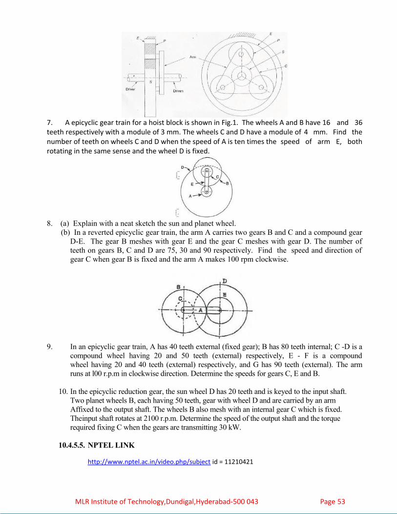
7. A epicyclic gear train for a hoist block is shown in Fig.1. The wheels A and B have 16 and 36 teeth respectively with a module of 3 mm. The wheels C and D have a module of 4 mm. Find the number of teeth on wheels C and D when the speed of A is ten times the speed of arm E, both rotating in the same sense and the wheel D is fixed.
8. (a) Explain with a neat sketch the sun and planet wheel. (b) In a reverted epicyclic gear train, the arm A carries two gears B and C and a compound gear
D-E. The gear B meshes with gear E and the gear C meshes with gear D. The number of teeth on gears B, C and D are 75, 30 and 90 respectively. Find the speed and direction of gear C when gear B is fixed and the arm A makes 100 rpm clockwise.
9. In an epicyclic gear train, A has 40 teeth external (fixed gear); B has 80 teeth internal; C -D is a compound wheel having 20 and 50 teeth (external) respectively, E - F is a compoundwheel having 20 and 40 teeth (external) respectively, and G has 90 teeth (external). The arm runs at l00 r.p.m in clockwise direction. Determine the speeds for gears C, E and B.
10. In the epicyclic reduction gear, the sun wheel D has 20 teeth and is keyed to the input shaft.Two planet wheels B, each having 50 teeth, gear with wheel D and are carried by an armAffixed to the output shaft. The wheels B also mesh with an internal gear C which is fixed. Theinput shaft rotates at 2100 r.p.m. Determine the speed of the output shaft and the torquerequired fixing C when the gears are transmitting 30 kW.
10.4.5.5. NPTEL LINK
http://www.nptel.ac.in/video.php/subject id = 11210421
MLR Institute of Technology,Dundigal,Hyderabad-500 043 Page 53