k.ii l!iai ii lull m li*iiresult, mobile communication requirements are on the rise, and personal...
TRANSCRIPT

NAVAL POSTGRADUATE SCHOOLADA23 6Monterey, California
I AD-A283 465
K.ii� l!iai ii lull m li*ii
DTICI•ELECTE ••uslg 191199
THESIS .-.
PERSONAL COMMUNICATIONS SERVICES:IMPROVING THEATER DEPLOYABLE COMMUNICATIONS
FOR THE 21ST CENTURY
by
Ro•ald C. CourDyer,Jr.
Jumn, 1994
Co-Advisors: Carl R. JonesDan C. Boger
Approved for public release; distribution is unlimited.
h., 94-2639194 8 18 1 62

REPORT DOCUMENTATION PAGE Form Approved OMB No. 0704
Public reportiag burdem for this collection of infornationa is etimated to average 1 hour per response. including the time for reviewing insruction. searching¢usiung data sources. athenng and masi-•-asn the data needd, and compietiag and reviewing the collection of information. Send comments regarding thisbum"de uimue or any other aspect of this collection of information i•nluding suggestions for reducing this burden, to Wshingtoa Headqumters Services.Directorat for laformatia Operations and Repmo 1215 Jefferson Davis Highway. Suite 1204. Arlington. VA 2=0---4302..and to the Office of Managementand Budget. Paperwork Reduction Project (0704-0138)Washigtoa DC 20503.
1. AGENCY USE ONLY (Leave btank) 2. REPORT DATE 3. REPORT TYPE AND DATES COVEREDJune, 1994 Master's Thesis
4. TITLE AND SUBTITLE Personal Communications Services: 5. FUNDING NUMBERSImproving Theater Deployable Communications for the 21st CenturyUNCLASSIFIED
6. AUTHOR(S) Ronald C. Cournoyer, Jr.7. PERFORMING ORGANIZATION NAME(S) AND ADDRESS(ES) 8. PERFORMING
Naval Postgraduate School ORGANIZATIONMonterey CA 93943-5000 REPORT NUMBER
9. SPONSORING/MONITORING AGENCY NAME(S) AND ADDRESS(ES) 10. SPONSORING/MONITORINGAGENCY REPORTNUMBlER
11. SUPPLEMETARY NOTES The views expressed in this thesis are those of the author and do notreflect the official policy or position of the Department of Defense or the U.S. Government.
12a. DISTRIBUTION/AVAILABILITY STATEMENT 12b.
Approved for public release; distribution is unlimited. DISTRIBUTION CODEI *A
13. ABSTRACT (mnmwva 2W0 w&rk)Personal Communications Services (PCS) may be the key ingredient for vastly improved military
communications capabilities at the turn of the century. The Federal Communications Commission (FCC)defines PCS as "a family of mobile or portable radio communications services which could provideservices to individuals and businesses and be integrated with a variety of competing networks...theprimary focus of PCS will be to meet communications requirements of people on the move." Today'sgeneration of Theater Deployable Communications, which provides joint tactical communications todeployed forces, is the Tri-Service Tactical Communications (TRI-TAC) system. A description of TRI-TAC's family of equipment, network topology, typical employment, and critical limitations is presentedin this thesis. Five commercial Mobile Satellite Services (MSS) are described as viable candidates foraugmenting existing communications systems. Cellular design principles such as frequency reuse, cellsplitting, channel access methods, and propagation factors are also addressed. Finally, a framework forcomparison of the candidate MSS systems is proposed as a baseline for further studies into the mostbeneficial implementation of PCS into theater deployable communications systems for the future.
14. SUBJECT TERMS TRI-TAC Communications, Theater Deployable 15. NUMBER OFCommunications, Cellular Technology, Mobile Satellite Services. PAGES 80
16. PRICE CODE
17. SECURITY CLASSIRI- is. SECURITY CLASSIFI- 19. SECURITY CLASSIFI- 20. LIMITATION OFCATION OF REPORT CATION OF THIS PAGE CATION OF AB1STRACTUnclassified Unclassified ABSTRACT UL
UnclassifiedNSN 7540-01-280-5500 Standard Form 298 (Rev. 2-89)
Prescribed by ANSI Sid. 239-It
1

Personal Communications Services:Improving Theater Deployable Communications
for the 21st Century
by
Ronald C. Cournoyer, Jr.
Captain, United States Air ForceB.S., University of Massachusetts, 1987
Submitted in partial fulfillmentof the requirements for the degree of
MASTER OF SCIENCE IN SYSTEMS TECHNOLOGY(COMMAND, CONTROL, AND COMMUNICATIONS)
from the
NAVAL POSTGRADUATE SCHOOL
June, 1994
Author: _ _ __ __ __ _
0 i . C u n y r Jr.
Approved by: d u-'-CalR nes, Co-Advisor
___ an C. Boger, lvisor
Paul Moose, ChairmanCommand, Control, and Communications Academic Group

ABSTRACT
Personal Communications Services (PCS) may be the key ingredient for vastly improved
military communications capabilities at the turn of the century. The Federal Communications
Commission (FCC) defines PCS as "a family of mobile or portable radio communications services
which could provide services to individuals and businesses and be integrated with a variety of
competing networks...the primary focus of PCS will be to meet communications requirements of
people on the move." Today's generation of Theater Deployable Communications (TDC). which
provides joint tactical communications to deployed forces, is the Tri-Service Tactical
Communications (TRI-TAC) system. A description of TRI-TAC's family of equipment, network
topology, typical employment, and critical limitations is presented in this thesis. Five commercial
Mobile Satellite Services (MSS) are described as viable candidates for augmenting existing
communications systems. Cellular design principles such as frequency reuse, cell splitting,
channel access methods, and propagation factors are also addressed. Finally, a framework for
comparison of the candidate MSS systems is proposed as a baseline for further studies into the
most beneficial implementation of PCS into theater deployable communications systems for the
future.
NTIS oRA&t/DTIC TAB 5
Un i 3o vlO d o0Tut f ct ion
By_Distribut iou/
AvalabilItY 0o0do0Avail and/or
Dist special

TABLE OF CONTENTS
I. INTRODUCTION ............... ..
II. TRI-TAC . . . . . . . . . . . . . . . . . . . . . 4
A. OVERVIEW .................. ................... 4
B. TRI-TAC FAMILY OF EQUIPMENT. ......... 4
1. TTC-39A Circuit Switch. ......... 5
2. TYC-39 Message Switch. ......... . 6
3. TSQ-111 Communications Nodal Control
Element ............... ................ 6
4. Transmission Assemblages ....... ........ 7
a. Digital Group Multiplex Equipment 7
b. Ground Mobile Forces Equipment . . . 8
C. NETWORK TOPOLOGY .............. ............... 9
1. Air Force Component Headquarters . 9
2. Tactical Air Base ... ......... .i. .... 11
3. Joint Message Switching ... ......... .. 13
D. SUMMARY ............. ................... .. 14
III. DESERT SHIELD/DESERT STORM COMMUNICATIONS . . .. 16
A. BACKGROUND .......... .................. .. 16
B. EMPLOYMENT OF TRI-TAC DURING DS/DS ........ .. 16
1. Scope of Communications ... ......... .. 16
2. Switching and Transmission Networks . . . 18
iv

a. Voice Network ..... ........... .. 19
b. Message Network ... .......... .. 19
c. Data Network ...... ............ .. 19
d. Satellite Network ................. 20
C. LIMITATIONS ........... ................. .. 21
1. General Observations from DS/DS ..... .. 21
2. Specific Problems from DS/DS ...... .. 21
a. Voice Network Problems ......... .. 22
b. Data Network Problems .. ....... .. 22
D. SUM4ARY ..................................... 24
IV. THEATER DEPLOYABLE COMMUNICATIONS FOR THE FUTURE . 25
A. LESSONS LEARNED ......... ............... .. 25
B. GLOBAL REACH, GLOBAL COMMUNICATIONS ..... 25
C. THE FUTURE OF THEATER DEPLOYABLE
COMMUNICATIONS ......... ............... .. 26
1. Theater Deployable Communications Goal 26
2. Theater Deployable Communications
Characteristics ..... ............ .. 27
3. Theater Deployable Communications
Impacts ......... ................ 27
D. AIR FORCE INITIATIVES ....................... 28
V. CELLULAR TECHNOLOGY ........ ................ .. 30
A. CELLULAR DESIGN PRINCIPLES .... .......... .. 30
v

1. Background ......... ............... .. 30
2. Frequency Reuse ...... ............ 32
3. Cell Splitting ..... ............. .. 33
B. RF PROPAGATION LIMITATIONS .... .......... .. 33
1. Free Space Propagation Loss (FSPL) . . 34
2. Foliage Loss ....... .............. 34
3. Adjacent Channel Interference ........ .. 35
4. Cochannel Interference .. ........ ... 35
5. Multipath Propagation .... .......... .. 35
a. Delay Spread ...... ............ .. 35
b. Rayleigh Fading ... .......... .. 36
c. Doppler Shift ..... ........... .. 36
6. Noise .......... .................. .. 36
C. CHANNEL ACCESS METHODS ...... ............ .. 37
1. Frequency Division Multiple Access . . . 37
2. Time Division Multiple Access . ......... 38
3. Code Division Multiple Access . ......... 39
a. Frequency-hopping CDMA ......... .. 39
b. Direct-sequence CDMA ... ........ .. 40
c. CDMA Advantages ... .......... .. 40
D. SUMMARY ............. ................... .. 41
VI. COMMERCIAL MOBILE SATELLITE SERVICES .. ...... 42
A. OVERVIEW ............ ................... .. 42
B. CANDIDATE MSS SYSTEMS ..... ............ .. 42
vi

1. GLOBALSTAR ............... 44
a. Basic Description ... ......... .. 44
b. Technical Characteristics ..... 44
c. Primary Services .... .......... .. 45
2. IRIDIUM .......... ................. .. 45
a. Basic Description ... ......... .. 45
b. Technical Characteristics ..... 45
c. Primary Services .... .......... .. 46
3. ORBCOMM .......... ................. .. 47
a. Basic Description ... ......... .. 47
b. Technical Characteristics ..... 47
c. Primary Services .... .......... .. 48
4. ODYSSEY .......... ................. .. 48
a. Basic Description ... ......... .. 48
b. Technical Characteristics ..... 48
c. Primary Services .... .......... .. 50
5. INMARSAT ......... ................ 50
a. Basic Description ... ......... .. 50
b. Technical Characteristics ..... 50
c. Primary Services . ................. 51
VII. FRAMEWORK FOR COMPARISON ..... ............ .. 52
A. PURPOSE ............. ................... .. 52
B. SCOPE ............. .................... 52
C. DESIGN ............ .................. .. 53
vii

1. Assumptions ............... 53
2. Factors .......... ................ 53
3. Setup ................................. 55
4. Measures . . . . . . . . . . . . . . . . 56
a. Measures of Performance ...... .. 57
b. Measure of Effectiveness ........ .. 59
c. Measure of Force Effectiveness 60
5. Method ........... ................. .. 61
D. OTHER CONSIDERATIONS ...... ............. .. 62
VIII. CONCLUSIONS ........... .................. 65
LIST OF REFERENCES ........... .................. 67
INITIAL DISTRIBUTION LIST ........ ............... 71
viii

I. INTRODUCTION
Within the past few years, there has much discussion on
topics such as C41 for the Warrior, Global Command and Control
System, Information Warfare, and a New World Order. As a
result, mobile communication requirements are on the rise, and
personal communications services (PCS) have emerged as the
focus of much attention.
PCS is a general term which encompasses a variety of
mobile communications services. It has materialized from
numerous technologies dealing with digital modulation schemes,
cellular and wireless telephones, low earth orbiting satellite
applications, and evolving network protocols. PCS has been
described by various communications journals in the following
ways:
1. PCS is a service not a particular technology. PCS draws
on the technologies of digital modulation, cellular and
cordless telephones, and sophisticated network protocols.
Most PCS proposals envision a portable lightweight instrument
providing users with access to a ubiquitous public network.
[Ref. 1: p. 52]
2. PCS is a generic term referring to mobile communication
services in which the user possesses a personal handset or
cordless telephone that can be used in a number of pedestrian,
office, residential and vehicular settings. [Ref. 2]
1

3. PCS encompasses a broad range of radio communications
services that free individuals from the constraints of the
wireline public switched telephone network and enable them to
communicate when they are away from their home or office
telephone. [Ref. 3]
4. With PCS, we can communicate from person to person,
regardless of where we are physically located. While PCS as
a class of services embraces a wide range of capabilities,
from simple paging and telephony to more advanced
fuictionality, the basic benefit is the ability to communicate
from virtually anywhere to virtually anywhere else. [Ref. 4:
p. 30]
The Federal Communications Commission (FCC) defines PCS
as "a family of mobile or portable radio communications
services which could provide services to individuals and
businesses and be integrated with a variety of competing
networks...the primary focus of PCS will be to meet
communications requirements of people on the move." [Ref. 5:
p. 22]
Personal Communications Services may be the key
ingredient for vastly improved military communications
capabilities at the turn of the century. Today's generation
of Theater Deployable Communications (TDC), which provides
joint tactical communications to deployed forces, is the Tri-
Service Tactical Communications (TRI-TAC) system. A
description of TRI-TAC's family of equipment, network
2

topology, typical employment, and critical limitations will be
presented in the upcoming chapters. Then, in order to provide
a better understanding of the technical issues concerning PCS,
cellular design principles such as frequency reuse, cell
splitting, channel access methods, spread-spectrum techniques,
and radio frequency propagation factors will also be
addressed. Once a technical foundation has been established,
five commercial Mobile Satellite Services (MSS) will be
presented as viable candidates for augmenting existing
communications systems. A brief description of each MSS
system will be given with particular attention to important
technical characteristics and subscriber services. Finally,
a proposed framework for comparison of the candidate MSS
systems will serve as a baseline for further studies into the
most beneficial implementation of PCS into the current system.
In the end, this thesis will identify several deficiencies in
the current TDC system, propose several MSS augmentations, and
provide a framework for demonstrating the technical
feasibility, additional capabilities, and benefits of
incorporating PCS into theater deployable communications
systems for the future.
3

II. TRI-TAC
A. OVERVIEW
The existing joint communications program, Tri-Service
Tactical Communications (TRI-TAC), provides the primary
Theater Deployable Communications (TDC) for Joint Task Force
(JTF) combat operations. TRI-TAC was conceived in 1971 to
foster communications interoperability among the services
through a standardized suite of tactical switched
communications equipment. TRI-TAC is the Air Force's current
"common-user" tactical communications system used to
inter'ionnect deployed bases, installations, and headquarters
elements with each other and rear echelon support
organizations. Essentially, a TRI-TAC deployment provides the
same core services and capabilities available on a typical
fixed Air Force base. In short, TRI-TAC is a complete TDC
package which is totally interoperable within itself and with
existing service systems, including the Defense Communications
System (DCS) and NATO systems. This chapter will introduce
the TRI-TAC family of equipment and the network topologies
typically employed during JTF operations.
B. TRI-TAC FAMILY OF EQUIPMENT
Functionally, TRI-TAC consists of voice, record and data
terminals, automatic circuit and message switches, automated
technical control facilities, multiplexing equipment, and
transmission assemblages [Ref. 28: p. 87]. Additionally, a
4

standardized communications security (COMSEC) suite provides
the TRI-TAC system with end-to-end security throughout its
tactical communications network. While a detailed discussion
on COMSEC is beyond the scope of this paper, the major
equipment associated with TRI-TAC's primary services will be
addressed below.
The TRI-TAC system provides the end-user with voice,
record (message) and data communications via automatic circuit
and message switches. The heart of a TRI-TAC communications
network is made up of the TTC-39A Circuit Switch (CS) and TYC-
39 Message Switch (MS).
1. TTC-39A Circuit Switch
The TTC-39A CS is a tactical four-wire, modular,
automatic telephone central office [Ref. 24: p. B-i]. It
supports 744 total external lines (96 analog, 648 digital) at
the standard TRI-TAC circuit and trunk group channel rates of
16/32 kbps, and also provides limited interfaces to commercial
analog central office and PBX equipment. The TTC-39A can also
trunk to other TTC-39As, the TYC-39 MS, unit level
transportable switchboards, such as the SB-3865, and DSN
switches for connectivity into the DCS. The two TRI-TAC
telephones routinely used with a TTC-39A switch are the KY-68
Digital Secure Voice Terminal and TA-954 Digital Nonsecure
Voice Terminal. These ruggedized terminals interface with the
switch at standard TRI-TAC loop rates of 16/32 kbps, using
Continuously Variable Slope Delta (CVSD) modulation. A
5

variety of two-wire and four-wire analog instruments are sup-
ported by the TTC-39A version, including the TA-838 and STU-
III. Finally, the TTC-39A CS provides limited nodal control,
as well as extensive circuit and trunk testing capabilities.
2. TYC-39 Message Switch
The TYC-39 MS is a 50-line store-and-forward message
switch [Ref. 24: p. B-1]. An appropriately accredited TYC-39
can handle both General Service (GENSER) or "R" traffic, which
includes classification levels up to and including Top Secret
and SIOP, and Defense Special Security Communications System
(DSSCS) or "Y" traffic, which includes SCI and other sensitive
information requiring special handling. The TYC-39 supports
interfaces with other message switches, such as AUTODIN, via
interswitch trunks (ISTs), and standard Mode I and II terminal
interfaces. The TYC-39 can trunk at the TRI-TAC channel rate
of 16 kbps, with a 50-line capacity, providing increased
message throughput in a tactical battlefield environment.
Like the TTC-39, the TYC-39 has integrated test equipment for
troubleshooting ISTs and message circuits.
3. TSQ-111 Communications Nodal Control Element
For technical control, the TSQ-111 Communications
Nodal Control Element (CNCE) is the "nerve center" of a TRI-
TAC communications installation. This S-280 shelter-mounted
component manages communications resources, monitors equipment
and circuit quality, and detects and isolates faulty or
degraded circuits. It accomplishes these functions through a
6

suite of fully programmable automated test equipment, and a
computer-controlled circuit rerouting capability. The CNCE
serves as the central interface between the circuit/message
switches and transmission assemblages. External interfaces to
the TSQ-111 equipment shelter are accomplished using standard
26-pair copper cable or coaxial cable. The TSQ-11 has both
an analog and digital capability [Ref. 24: p. B-3].
4. Transmission Assemblages
TRI-TAC transmission assemblages can be divided into
two main types: Digital Group Multiplex (DGM) and Ground
Mobile Forces (GMF).
a. Digital Group Multiplex Equipment
The DGM equipment includes the TRC-170 digital
tropospheric scatter radios, TSQ-146 Multiplexer Van, and RT-
1462 TSSR (Tropo-Satellite Support Radio). Large transmission
and switching assemblages, such as the TRC-170 or TTC-39A, are
housed in standard portable equipment shelters (S-250, S-280,
or S-530) and have a combined weight of approximately 8,500
lbs [Ref. 26: p. 18-9]. When being transported by M-720 or M-
880 mobilizers, the physical dimensions of these components
are approximately 8' x 20'; plus, a pair of 9.5 or 6.0 foot
diameter antennas must be transported separately. The TRC-170
radio system is a 32-channel, maximum 2048 kbps, tropospheric
scatter radio that provides reliable, bulk-encrypted
communications links between bases separated by up to 150
miles [Ref. 26: p. 18-2]. For shorter links, not to exceed 10
7

miles, the RT-1462 TSSR can be used for line-of-site (LOS)
microwave radio communications between a remote
tropo/satellite site and the main communications facility.
The TRC-170 can also be configured in a LOS mode for shorter
distances if necessary. Various factors including
atmospherics and terrain impact the actual attainable range in
any given situation. The TRC-170 family of transmission
equipment performs the primary wideband communications
trunking between major nodes of a deployed JTF.
b. Ground Mobile Forces Equipment
GMP equipment includes the TSC-94A and TSC-100A
tactical multi-channel satellite terminals which provide the
primary theater satellite communications capability. The TSC-
94A (8-foot diameter antenna) is a point-to-point SHF terminal
which can support a maximum of 24 individual channels. The
TSC-100A (8/20-foot diameter antenna) can support up to 72
individual channels or be configured in a nodal "hub-spoke"
network configuration with up to four other terminals [Ref.
24: pp. B6-B7]. Despite the different nomenclature, DGM and
GMF equipment are completely interoperable, along with the
entire TRI-TAC family, through a standard multiplex
architecture based on a 16/32 kbps CVSD channel rate.
The previously described equipment (switches,
technical control, and transmission media) form the core of
the TRI-TAC family of equipment.
8

C. NITWORK TOPOLOGY
The TRI-TAC communications system typically supports Air
Force bare base operations; Desert Shield/Desert Storm (DS/DS)
is a good example of what the Air Force terms "bare base
operations." The system supports Command and Control (C2 ) at
all levels by providing reliable and flexible communications
capabilities. Specialized C2 data, intelligence products,
weather forecast data, and general purpose information all
pass through a deployed TRI-TAC system. TRI-TAC systems not
only connect bases, installations, and headquarters elements
within a theater of operations, they also extend connectivity
back to the CONUS and into other theaters by way of DCS
gateways. The remainder of this section demonstrates how TRI-
TAC components are used to support a typical Air Force
deployment within a Joint Task Force (JTF) framework.
1. Air Force Coaonent Headquarters
Figure 1, on the next page, illustrates how key TRI-
TAC components support an Air Force Component Headquarters
(AFCH) when deployed as part of a JTF [Ref. 44].
The AFCH is tied to the JTF HQ via tropospheric
scatter radio (TRC-170) and/or SHF satellite (TSC-100A); the
distance between the two headquarters generally determines the
transmission medium used. If possible, both media are used
for redundancy and added capacity. Links to the other service
components are established in basically the same manner.
9

To TacticalAirbase
AF Component HQ (AFCH) -Qr
TTC-39 TYC-39 I
To Tactical'Airbase ' S-1
Interswitch Trunksr TRC-170 C-1A :Global Weather
Intelligence DataI I Etc.I /
I TRC-170
rI AUTODIN (R/Y) HQ Q(Dcs\ DSN Non-Secure Vote•iEM Global Weather UM
Specal Circuit
Figure I. Air Force Component Headquarters Network
10
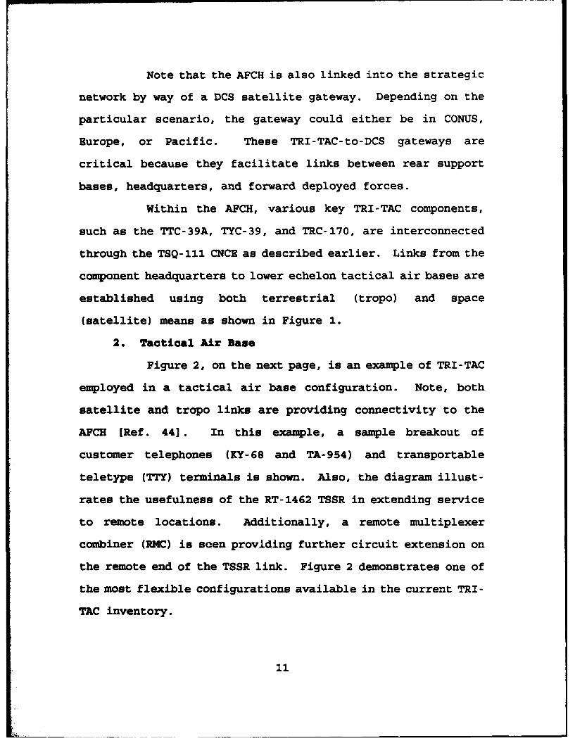
Note that the AFCH is also linked into the strategic
network by way of a DCS satellite gateway. Depending on the
particular scenario, the gateway could either be in CONUS,
Europe, or Pacific. These TRI-TAC-to-DCS gateways are
critical because they facilitate links between rear support
bases, headquarters, and forward deployed forces.
Within the AFCH, various key TRI-TAC components,
such as the TTC-39A, TYC-39, and TRC-170, are interconnected
through the TSQ-111 CNCE as described earlier. Links from the
component headquarters to lower echelon tactical air bases are
established using both terrestrial (tropo) and space
(satellite) means as shown in Figure 1.
2. Tactical Air Sase
Figure 2, on the next page, is an example of TRI-TAC
employed in a tactical air base configuration. Note, both
satellite and tropo links are providing connectivity to the
AFCH [Ref. 44]. In this example, a sample breakout of
customer telephones (KY-68 and TA-954) and transportable
teletype (TTY) terminals is shown. Also, the diagram illust-
rates the usefulness of the RT-1462 TSSR in extending service
to remote locations. Additionally, a remote multiplexer
combiner (RMC) is seen providing further circuit extension on
the remote end of the TSSR link. Figure 2 demonstrates one of
the most flexible configurations available in the current TRI-
TAC inventory.
11

From KY-68/C SUBSCRIBERS
C-94A TT-39A TA-954SSUBSCRIBERS
FromTS11AFCH
RT-1 462
WXiTT
b AUTODIN RMC RemoteTerminal Location
Figure 2. Tactical Air Base Network
12

3. Joint Message Switching
Figure 3 below depicts a typical joint message
switching network [Ref. 44].
(Gateway)TTY
Air Force /.TTY Component "TYC-R39
TYC-39TY-3
TacticalTT
(Gateway)
Figure 3. Joint Message Switching Network
13

Here, the importance of network survivability and
redundancy is evident with the criss-crossing interswitch
trunks (ISTs) in a mesh configuration. The 16 kbps ISTs,
linking the TYC-39 Message Switches, are carried over various
transmission media, including tropo, satellite, and cable.
Numerous TTY terminals are also shown as direct connections
off the TYC-39s. The DCS satellite gateways provide essential
circuits between the TYC-39s and AUTODIN Switching Centers
(ASCs). In some cases, high-frequency (HF) multi-channel
radio links into DCS HF gateways are established as backups to
the primary satellite links; however, HF AUTODIN entries
afford a much lower data rate (75-300 baud vice 1200-2400
baud). Figure 3 depicts just one of many possible joint
message switching network topologies.
D. SMO1MY
From its inception back in 1971, the TRI-TAC program has
evolved to satisfy the need for interoperable and reliable
comunuications at the Joint Task Force level. In practice,
TRI-TAC has served the military services, and, in particular,
the Air Force well. However, changes in technology and
operational requirements have created some areas where TRI-TAC
falls short. Operation Desert Shield/Desert Storm highlighted
many of these problems which have acted as a stimulus for many
proposed improvements. Chapter IV will identify the most
significant recommendations for new Air Force tactical
coummications initiatives. These initiatives, coupled with
14

TRI-TAC's interoperability strengths and the amount of
resources already invested, can provide the military services
with a solid core of tactical communications well into the
foreseeable future.
15

III. DESERT SHIELD/DESERT STORK CROWUNICATIONS
A. BACKGROUND
From TRI-TAC's beginnings in the Air Force Battlefield
Environment (AFBE) in the early 1980s to recent operations in
the Persian Gulf, numerous limitations have surfaced. Changes
in technology and operational requirements have presented
areas where the aging TRI-TAC equipment is deficient. More
specifically, the lack of high-speed data and computer network
support, and inadequate commercial interface capabilities have
caused the greatest impact on recent military operations.
This chapter describes TRI-TAC's employment and some of its
more significant downfalls observed during Desert
Shield/Desert Storm (DS/DS).
B. MPLOYMENT OF TRI-TAC DURING DS/DS
1. Scope of Coanmications
Desert Shield/Desert Storm proved beyond a doubt
that C41 is as fundamental to the fight as bombs, bullets, and
airplanes. When properly employed, C41 becomes a vital force
multiplier [Ref. 30: p. 4]. The forms of communications
provided were voice, data, facsimile, record (message)
communications, imagery, video, and e-mail. Mission/support
areas covered included: Joint Forces Air Component Commander
(JFACC), counter air, close air support (CAS), interdiction,
suppression of enemy air defense (SEAD), refueling, airlift,
search and rescue (SAR), special operations, and intelligence.
16

Additional mission areas included infrared electronic warfare
(EWIR), air traffic control, aeromedical evacuation, supply,
logistics, munitions, transportation, training, security
police, and Office of Special Investigations (OSI). Other
supported functions were finance, legal, medical, postal,
combat control teams, combat camera, information management,
audio visual services, public affairs, civil engineers, Moral
Welfare and Recreation (MWR) services, chaplain, contracting,
weather, and other airbase support operations [Ref. 24: p. 7].
Clearly, providing the required communications for employment
of forces into a bare base environment can be quite a complex
task. Communications requirements for all Air Force MAJCOMs
and FOAs are consolidated and maintained by the Communications
Requirements Data Base (CRDB).
The scope and pace of escalation of DS/DS was
unprecedented. In fact, the operations in the Persian Gulf
have been called "the largest single communications
mobilization in military history." [Ref. 18: p. 25]. The
scope of USAF activities alone are included in Table 4-1 on
the following page [Ref. 18: p. 24]. It took more than 200 C-
141 sorties to airlift tactical communications equipment to
the Gulf [Ref. 18: p. 25]. During the early stages, these
aircraft were not readily available for moving the bulky
tactical and transmission equipment since the initial airlift
was allocated towards the buildup of combat forces in theater.
While Air Staff planners estimated sufficient tactical
17

communications resources f or 13 airbases, in the end, the Area
of Responsibility (AOR) included 25 airbases. Compounding
this serious shortfall, the Air National Guard (ANG), which
had not been called to active service, possessed nearly 80
percent of Air Force tactical communications resources. As it
turned out, the ANG provided only two squadrons and only about
10 percent of the overall resources [Ref. 18: pp. 25-26]. As
a result, a sparse network of tactical communications were
stretched to the limits in providing essential connectivity
for theater-wide communications.
TABLE 4-1. SCOPE OF USAF ACTIVITIES
Quantity Description
12 Combat Communications Squadrons2300+ USAF personnel1500 short tons of equipment7000+ radio frequencies26 SHF earth terminals3 commercial T-1 satellite terminals1050 USAF circuits1000 miles of terrestrial systems29 tropo and microwave links6 DCS entry points72 AUTOVON trunks19 automatic telephone switches17 manual switches3 message switches132,012 messages transmitted1,293,775 messages received59 communications centers29,542,121 calls350,000 air operations for Desert Shield225,000 air operations for Desert Storm950+ pages per Air Tasking Order
2. Switching and Transmission Networks
The TRI-TAC switching and transmission equipment
formed a terrestrial system which interconnected the Joint
18

Task Force Headquarters, its component air, land, and sea
commands and all locations within the AOR. The final system
configuration stretched over 1000 miles and was comprised of
29 links of tropospheric and microwave transmissions [Ref 18:
p. 30].
a. Voice Network
The voice network contained over 300 trunks
connecting 25 TTC-39s in the theater to 8 DSN gateways (4
U.S., 3 Europe, 1 Pacific) [Ref. 18: p. 13]. Furthermore, it
contained 19 automatic and 17 manual switchboards that
processed nearly 30 million calls through 72 AUTOVON trunks
[Ref. 18: p. 31].
b. Message Network
The message network contained 26 trunks
connecting 20 TYC-39s in the theater to 5 AUTODIN switching
centers (3 U.S., 1 Europe, 1 Pacific). Ultimately, 286
message centers were supported worldwide with an average
delivery time of 23 minutes [Ref. 18: p. 15].
c. Data Network
Whereas TRI-TAC evolved to satisfy most of the
voice and message traffic needs, little capability existed to
cope with the data communications bottlenecks involved with
large-volume, high-speed traffic of Is and Os. All four DDN
networks were heavily used: MILNET was used for unclassified
common-user service; DSNET1 was used for Secret level common-
user traffic; DSNET2 was used for Top Secret and WWMCCS users;
19

DSNET3 was used for Top Secret/SCI intelligence support.
d. Satellite Network
The flexibility of space communications was
demonstrated through extensive satellite usage in an effort to
meet increasing traffic demands throughout the Gulf War.
Initially, SHF Defense Satellite Communications System (DSCS)
presence in the region consisted of only two satellites (DSCS
East Atlantic and DSCS Indian Ocean) which handled a total DOD
traffic throughput of about 4.5 Mbps (70 voice circuits
equivalent) [Ref. 18: p. 122]. As hostilities heightened, so
to did the need for greater communications throughput.
As U.S. forces in the Gulf peaked, a total of
4 DSCS satellites (East Atlantic, Indian Ocean, Indian Ocean
Reserve, West Pacific Reserve) covered the region. The
throughput climbed to 68 Mbps (1,100 voice circuits
equivalent), and 110 earth terminals were deployed.
Additionally, 9 UHF satellites from FltSatcom/AFSatcom and
LeaseSat/Syncom, 2 experimental multiple access communications
satellites (MACSAT), 2 United Kingdom Skynet satellites, 1
NATO, 4 IntelSat, and 1 InmarSat satellites were all deployed
in support of coalition forces during DS/DS operations [Ref.
18: p. 123]. The Gulf conflict may be labeled as the first
space war, and as a British defense chief simply observed,
"The Gulf taught us that space has changed the whole nature of
warfare." [Ref. 18: p. 133]
20

C. LIMITATIONS
Changes in technology and operational requirements have
created areas where the existing TRI-TAC system falls short.
Operation Desert Storm demonstrated that tacticalcommunications are still plagued by incompatibilities andtechnical limitations. At CENTCOM corps and wing levels,a significant portion of the war was conducted overcommercial telephone lines because of the volume andcompatibility limitations of the military communicationssystem [Ref. 42: p. 22].
This section ioes not discuss all the limitations of TRI-TAC,
rather it focuses on some of the key shortfalls observed
primarily from DS/DS operations.
1. General Observations from DS/DS
Desert Shield/Desert Storm (DS/DS) observations of
deployed C4 systems [Ref. 31]:
- Inflexible equipment design-- Current deployed systems are large and heavy-- Automated deployed system hardware/software could not
expand-- CONUS automated systems are not structured to support
deployed forces- Inadequate conzmmications capacity
-- Unique standards and inefficient communicationslimited throughput
-- Large capacity networks needed for sustainingoperations
- Limited interoperability-- Joint ATO planning/dissemination hampered by non-
standard automated systems-- Airborne communications and ground networks are not
fully integrated.
2. Specific Problems from DS/DS
While not all of the communications problems from
DS/DS can be identified here, this section hopes to highlight
some of the more critical ones noted in Alan D. Campen's book,
The First Information War [Ref. 18].
21

a. Voice Network Problems
Limited interswitch trunking resulted in poor
voice switched network performance, with an average intra-
theater grade of service ranging from only 40% to 85% call
completion success rates [Ref. 18: p. 13]. The Ninth Air
Force chief network systems engineer summed up the problems as
a "disaster for call completion rates.. .we had a grid-locked,
voice switched network." At one point, completion rates were
reported as low as 5 percent for Routine, 40 percent for
Priority, and 65 percent for Immediate [Ref. 18: p 32]. The
unexpected use of modem-connected personal computers and
facsimile machines over the circuit switched networks further
compounded problems. The heavier traffic demands, coupled
with many analog-to-digital conversions, and an abundance of
protocol problems, all proved too taxing for a system which
was not engineered to accommodate such applications [Ref. 18:
pp. 13-14].
b. Data Network Problems
The lack of a pre-planned common-user data
network for tactical communications via personal computers led
to a number of problems. Poor circuit and end-to-end
performance were the result of noisy, high error rate tactical
circuits operating over non-commercial standard 16 kbps links.
Also, due to traffic overload and corrupt address routing
tables at DDN gateways, many Tranmission Control Protocol
(TCP) timeout errors often occurred. Finally, the complex
22

configuration of routers, bridges, packet switches and
satellite circuits were a network management nightmare [Ref.
18: p. 16]. As one Air Staff planner put it, "We had no plan
for data communications." [Ref. 18: p. 32]
The lack of tactical communications networks that could
provide the required in-theater data communications
connectivity proved to be a major headache. Tactical planners
greatly underestimated -he sheer volume and variety of data
required to support automated combat support systems. The new
battlefield environment included literally thousands of
personal computers. In the end, it is estimated that over
3000 computers were linked back to hosts in the U.S., mainly
over leased commercial circuits [Ref. 18: pp. 32-33]. From
the intelligence community's perspective, the tactical
networks did not come close to meeting the data-intensive
demands for supplying high-quality imagery down to the
appropriate combat echelons. As a result, many units were
limited to only hard copy photos delivered by helicopter or
truck, often with unsatisfactory time delays [Ref. 18: p. 55].
In the author's assessment, the existing tactical systems
could not possibly meet the excessive data communications
requirements then, and most certainly, TRI-TAC will not be
able to fully handle the new-age battlefield automation needs
of the future.
23

D. SMOIARY
The existing theater deployable communications, TRI-TAC,
are not geared for modern day warfare. TRI-TAC is primarily
suited for simple voice and message traffic, but clearly, the
widespread proliferation of personal computers, local area
networks, high resolution imagery, and other high-speed data
communications services have prompted the need for change.
Operations during DS/DS demonstrated critical problems in
supporting high-speed data commnmications, computer networks,
and commercial interfaces as previously discussed.
A potentially disruptive disconnect in planning allowedcombat forces to arrive in the Persian Gulf without thecommunications equipment needed to plan, launch, andcontrol air operations. And when the resources didarrive, they provided only marginal support for criticaldata communications, the service needed most in modern airwarfare [Ref. 18: p. 35].
The TRI-TAC program has served its purpose for interoperable
and reliable communications over the past couple decades, but
advancements in technology and increased operational
requirements call for theater deployable communications to
keep up with the pace.
24

IV. THEATER DEPLOYABLE CCUNXNICATIONS FOR TIE FUTURE
A. LESSOUS LEARNED
Lessons learned from DS/DS show that reliable, long-range
mobile communications are essential on the modern battlefield.
Theater Deployable Communications (TDC) must be capable of
supporting a full range of communications and providing timely
and accurate situational awareness for effective command and
control during highly fluid conflicts.
DS/DS demonstrated the inadequacy of current tacticalcommunications systems and the value of a common pictureof the battlefield to support effective Command andControl (C2) on-the-move (OTM). A persistent problemexperienced was that the fighting forces moved faster thanthe communications infrastructure could effectivelysupport. This, coupled with an incomplete common pictureof friendly and enemy information, had a negative impacton the management of the battle [Ref. 27: p. A-15].
Building an up-to-date graphical common picture of the
battlefield is a powerful tool for improving a tactical
conmander's situational awareness, and existing systems have
proved inadequate in this respect. Today's generation of
deployable communications equipment will not support
tomorrow's missions of power projection on a global scale.
D. GLOBAL REACH, GLOBAL CCOINICATIONS
The Air Force's Global Reach, Global Power concept calls
for communications which are small and lightweight for
mobility, modular and scalable for tailored force projection,
and seamless for rapid response on a global scale [Ref. 40].
Combat Air Forces' (CAF) Mission Need Statement (MNS) 311-92
25

on Theater Deployable Communications asserts the following:
The Air Force needs a lightweight, modular, integrateddeployable communications system to support command,control, intelligence, logistics, and other missionsupport functions throughout multiple employment scenariosfrom initial deployment through sustaining operations[Ref. 43].
As the author's observation, the U.S. military must increase
efficiency of current systems through improved transmission
switching, bandwidth management, information compression,
network management, and SATCOM usages. The new TDC concept
must look to commercial-off-the shelf (COTS) equipment for
multi-band satellite communications, network management,
modular switching, and other deployable systems which are
compatible with existing TRI-TAC, STU-III, and DDN systems
[Ref. 32].
C. THE FUTURE O THI&TZR DEPLOYABLE CONMUNICATIONS
1. Theater Deployable Communioations Goal
A primary goal of the TDC program must be to
transition from unique tactical to commercial-standards-based
switching and transmission systems. The intent is to reduce
life cycle costs, improve interoperability with strategic and
theater communications systems, optimize use of the existing
commercial communications infrastructure in theater, and to
provide additional capabilities not supported by equipment
currently in the inventory [Ref. 24: p. 20]. Furthermore, TDC
packages must be transportable by airlift, sealift, rail, or
truck. Size, weight, power requirements, and equipment set-up
26

times must be kept to an absolute minimum to support
transportation, deployment, and operations in a deployed
environment [Ref. 24: p. 54].
2. Theater Deployable Conmanications Characteristics
In response to the many observations, limitations,
and suggested improvements to existing TRI-TAC systems, the
future Theater Deployable Communications must possess the
following characteristics [Ref. 31]:
- Transportable (small, lightweight)
- Flexible (modular, scalable)
- Interoperable (common standards/protocols)
- Efficient (dynamic bandwidth management)
- Evolutionary (TRI-TAC compatible)
- Robust (multiple routing)
- Responsive (network management/control)
- Secure.
3. Theater Deployable Ccomunications Impacts
If actions are not taken to provide the essential
TDC for the future, then the U.S. military will continue to
suffer the following consequences, as experienced during DS/DS
operations [Ref. 31]:
- Coumunications will remain unresponsive to global reach,
global power requirements.
-- Too big, too heavy, too inflexible
-- Not available when the warfighter needs it
- Communications capacity will remain inadequate.
27
-- Slow ATO preparation and distribution
-- No real-time intelligence for BDA
- Deployed communications networks will remain unique.
-- Insufficient information for mission planning
-- Expensive integration costs
- Existing communications equipment will become expensive to
support and modify because of technology obsolescence.
The bottom line is, unless improvements are made to existing
systems, an integrated global information network will never
be realized, and future U.S. military operations will be
severely impacted.
D. AIR FORCE INITIATIMVS
In the author's opinion, the U.S. Air Force's vision is
focused in the right direction for improving communications in
upcoming years. Communications Squadron 2000 initiatives
require that "...deployable C41 systems must be modular,
lightweight, and much less airlift-intensive than the current
systems." [Ref. 38: p. 6] Further emphasizing the need for
improved TDC systems, the Communications Squadron 2000 concept
focuses on C41 support of expeditionary warfare by "equipping
the deployable communications units with lightweight, modular,
interoperable C41 systems" [Ref. 38: p. 8]. Looking to the
21st century, the Air Force's C41 must:
Shape a future where communications and automation tools,systems and people combine to surround every Air Forcedecision maker and war fighter with a transparentinfosphere providing, on demand, any information requiredfor the execution of the task at hand - reliably,securely, in any required form, anywhere (Ref. 30: p. 2].
28

Tomorrow's forces must be able to adapt, respond, and fight
over great distances, and the accompanying communications
systems must be ready, mobile, and able to meet changing
contingencies.
29

V. CELLULAR TECHNOLOGY
In meeting the needs of tomorrow's tactical
communications, a move towards PCS technologies may well serve
the military into the 21st century. Since PCS is heavily
based on cellular technology concepts, a brief discussion of
the most significant cellular principles will be presented in
this chapter. Subjects to be discussed will include: call
handoffs, roaming, frequency reuse, cell splitting, radio
frequency (RF) propagation limitations, and channel access
methods. After a technical foundation has been established,
the next chapter will address several mobile systems which
will employ many of the concepts presented here.
A. CELLULAR DESIGN PRINCIPLES
1. Background
Fundamentally, "cellular" is derived from the idea
that the communication architecture, at its root level, is
composed of individual cells which represent a specified
coverage area. A cell is traditionally represented as a
hexagon for convenience in depicting interlocking, non-
overlapping area coverage. Each cell contains its own
antennas, radio equipment, power plant, and data terminals
that collectively form the interface between the switching
center, called the mobile telephone switching office (MTSO),
and the mobile units [Ref. 15: p. 8].
30

Two key principles of cellular communications system
have to do with call handoffs and roaming. If a mobile
subscriber approaches a cell's boundary, where transceiver
signal strengths are near threshold levels, then an automatic
prompt is sent to the MTSO requesting a call handoff. In
response, the MTSO queries nearby cell sites for acceptable
mobile unit signal strengths, and establishes a call handoff
to a new cell site destination. The mobile set is
automatically switched to the correct frequency and power
levels to ensure uninterrupted service [Ref. 7: p. 32]. If a
mobile unit is operating outside the confines of its Cellular
Geographic Service Area (CGSA), then it is defined as roaming
[Ref. 7: p. 33]. The switch networking standard, IS.41,
handles the protocols for inter-system handoffs, or roaming.
The IS.41 roaming procedures allow cellular services to be
relayed to mobile subscribers regardless of the assigned CGSA
(Ref. 7: p. 34]. Both call handoffs and roaming are valuable
features handled by all cellular systems.
Typically, a mobile set consists of a control unit,
a transceiver, and a simple or•midirectional antenna system.
As a bit of trivia, the small personal handsets are referred
to as "portables," whereas the automobile phone sets are
referred to as "mobiles." Additionally, the mobiles use a
simple whip roof/glass-mounted antenna, with up to 3 dB gain,
and can transmit several watts of power, while the portables
usually employ a short telescopic antenna, with 0 dB gain, and
31

transmit on the order of milliwatts [Ref. 15: p. 171].
In discussing a cellular system structure, it is
important to consider the issues of capacity, coverage, and
performance. In doing so, the topics of frequency reuse and
cell-splitting will be covered.
2. Frequency Reuse
Establishing an efficient frequency reuse pattern is
the key ingredient to the cellular architecture. Cells must
be appropriately clustered to efficiently utilize the entire
frequency spectrum allocated. The frequency reuse pattern
determines the frequency reuse distance, D, as seen in the
below equation [Ref. 15: p. 52]:
D = R x (3xN)A
In this equation, D is the distance which must exist between
two cells of different clusters in order for the same
frequency to be used in both, without cochannel interference.
R is the radius of each cell, and N is the number of cells per
cluster in the reuse pattern.
For example, with a seven-cell reuse pattern, N=7,
and a cell site radius, R=10km, the required frequency reuse
distance, D, is 45.83 km. In comparison, reducing the cell
site radius to R=1 km results in a frequency reuse distance
of 4.583 km.
In the latter case, R=1 km allows us to reuse our
allocated frequencies more often within the total area of
coverage. As a result, the potential subscriber capacity is
32

greatly increased. Also, note that lower power transmitters
are needed as the cell sizes decrease; the smaller, low-power
PCS handsets are based on this concept.
3. Cell Splitting
Cell splitting also plays a key role in increasing
capacity and improving performance in heavily used cell areas.
As the key to congestion management, the original cell is
split into a number of smaller cells so that the assigned
frequency channels can be used more often. After splitting, a
greater number of channels are available, and thus, the
service capacity is increased for that area by a factor, N,
equal to the number of new cells created [Ref. 17: p. 42].
PCS typically deals with a cell site radius, R % 1
km, which is often referred to as a "microcell." The value of
R is largely determined by the cell site's transmitter power.
In the previous equation, D is directly proportional to R, so
reductions in R (down to about one kilometer) can result in
tremendous increases in spectrum efficiency. Additionally, as
R is reduced, transmitter power can also be reduced, and lower
frequency reuse distances can be achieved. These advantages
of microcell, or even smaller picocell, coverage areas are
significant benefits of future PCS concepts over the
traditional cellular systems.
B. RY PROPAGATION LIMITATIONS
in this section, the effects of the following limiting
factors on RF propagations are discussed:
33

1. Free Space Propagation Loss
2. Foliage Loss
3. Adjacent Channel Interference
4. Cochannel Interference
5. Multipath Propagation
6. Noise.
1. Free Space Propagation Lose (FSPL)
This RF propagation characteristic actually makes
the concept of cellular communications practical. After all,
if the signal strength did not diminish as a function of
distance, then frequency reuse between separate cells would
not be possible due to interference. However, within larger
cells having a radius of nearly 10 miles, FSPL must be
considered [Ref. 15: p. 102].
As examples of the FSPL impact on the standard
Advanced Mobile Phone System (AMPS), the following
attenuations are typical [Ref. 15: p. 102]:
- Free Space (ideal) - 20 dB / 10 miles
- Flat, open Earth's surface = 43.5 dB / 10 miles
- City (New York) - 50 dB/ 10 miles.
2. Foliage Lose
Any foliage along the path between the nmobile and
cell site contributes to the attenuation of the RF signal.
Much uncertainty is involved here, dependent on the sizes of
trees, branches, leaves, trunks, density of vegetation, season
of the year, and other related factors which can absorb RF
34

energy. For a cell of size R-10 miles, we approximate a
foliage loss to 20 dB for analysis purposes [Ref. 15: p. 116].
3. Adjacent Channel Interference
This occurs when the energy between adjacent
channels overlaps, resulting in destruction of the original
signal. As a result, adjacent frequency channels can not be
used within a given cell without proper filtering; note, extra
filtering boosts the cost of the transceiver components.
4. Coahannel Intezference
This may be the most important constraint on
cellular frequency reuse. Cochannel interference occurs when
different cell areas, using the same channel, are in
sufficient range for unintentionally intercepting each other's
transmissions. This is a primary factor of concern for
maintaining an acceptable cellular reuse distance, D, as
previously mentioned.
5. Multipath Propagation
This occurs when radio waves are reflected from
obstacles, or even the atmosphere, and can cause three primary
effects [Ref. 17: p. 213]:
a. Delay Spread
This results when a radio wave takes alternate
paths, of varying distances, from transmitter to receiver due
to reflections. Thus, by the time a single radio pulse is
received, its width has been spread.
35

b. Rayleigh Fading
This is a condition where many rapid fades
occur over time as a result of dramatic changes to the radio
wave's phase and amplitude. While similarly caused by
reflections as mentioned above, the signal also undergoes
rapid, deep fades in strength which clearly degrade signal
quality. In a mobile environment, the rate of fading is
compounded even further due to variations in the relative
motion of the radio waves to moving objects.
c. Doppler Shift
This describes the variations in frequency of
the received signal resulting from a mobile set relative to
the cell site. This shift can be significant enough to induce
a noticeable distortion since the transmitted power spectrum
is shifted off the nominal center frequency of the received
signal.
6. Noise
Noise can be categorized as either external or
internal, and can generally be described as any undesired
signal in a communication circuit. Internal noise, such as
thermal noise, arises from within the communications
components themselves. External noise, such as electric
motors, power lines, neon signs, and the like, pose the most
serious concerns to cellular operations.
All of the above RF propagation factors must be
considered when engineering a communications system with the
36
best signal-to-noise ratio (SNR) and overall performance
charactistics possible.
C. CNAHNKL ACCESS METHODS
Frequency allocations for PCS, around the 2 GHz range,
are currently under review by the Federal Communications
Commission [Ref. 5: p. 23]. With only 20 MHz (1910 - 1930
MHz) of the spectrum projected for unlicensed PCS usage, it is
clear that multiple access schemes must be employed for the
sharing of a single communication resource. This section
focuses on multiple access techniques such as:
1. Frequency Division Multiple Access (FDMA)
2. Time Division Multiple Access (TDMA)
3. Code Division Multiple Access (CDMA).
1. Frequency Division Multiple Access
This access scheme is used by the original analog
cellular system in the U.S. known as the Advanced Mobile Phone
Service (AMPS). The allocated frequency spectrum consists of
"a total bandwidth of 20 MHz in the 850 MHz region; typically,
"a single channel bandwidth is 30 kHz with guard bands serving
as buffer zones between adjacent channels [Ref. 14: p. 479].
With this scheme, a subscriber is assigned a
dedicated frequency channel for the duration of the call.
Upon call termination, the channel is once again available for
reallocation to another subscriber. Note that each mobile
unit must be frequency agile in order to be tuned to all
available frequencies.
37

2. Time Division Multiple Access
In this scheme, frequency channels are separated
into discrete time slots and assigned to different subscribers
at fixed time intervals. While FDMA uses frequency guard
bands, TDMA uses time guard slots to buffer between adjacent
signal transmissions [Ref. 14: p. 484]. With systems such as
the European Group Special Mobile (GSM) digital cellular
standard, a fixed number of time slots are grouped into a
frame, and then each frame corresponds to a separate frequency
channel [Ref. 6: p. 35]. Notice that this technique is really
a combination of TDMA and FDMA since all available frequencies
and time slots are available to the subscriber.
TDMA offers several advantages over FDMA, which
makes it the preferred choice for cellular applications [Ref.
7: pp. 73-74]: several subscribers can transmit over a single
frequency channel, thus permitting a more efficient use of the
RF spectrum; since continuous transmission is not necessary,
transmitter power can be better utilized, and duplexers are
not required; ease of reconfiguration, through software
upgrades, allows acceptance of changing bit-rate algorithms;
and TDMA provides better resistance to cochannel and adjacent
channel interference.
As a result of the above advantages, TDMA can
provide greater system capacity through greater freedom of
channel assignments among the cells in a given area.
38

3. Code Division Multiple Access
Employed by spread spectrum communication systems,
which have been used exclusively by the military for decades,
the CDMA method has only recently been adopted f or public
cellular system usages.
Spread spectrum methods mainly include frequency
hopping or direct sequence techniques. In both techniques the
signal power is spread out over the entire assigned bandwidth
rathepr than concentrated into a specific band. Additionally,
ex, aly low signal-to-noise ratios can be tolerated as
result of very high processing gains.
a. Frequency-hoppWin cZ
Frequency-hopping CDMA (FH-CDMA) assigns a
short-term frequency slot to a user for data transmission,
then after a brief interval of time, another frequency is
assigned for the next time interval, and so on, until the
entire message is sent. The frequency hopping pattern for
each user is generated by a pseudo-random code. The
processing gain for FH-CDMA corresponds to the ratio of the
total frequency spectrum bandwidth to the frequency bandwidth
for each hop [Ref. 11]:
GH - W/ R
where W., is the system bandwidth and R is the data rate.
If a FH system has a bandwidth of 850 Mhz and transmits data
at a rate of 1.2 kbits/sec, then we get the following
processing gain:
39

iGFH- 850 Mhz/1200 bps - 708,333 1-> 10 iog 1 0 (708,333)
GFH - 58.5 dB
Clearly, as we divide the allocated spectrum into more
segments, with smaller bandwidths for each hop, then we can
achieve tremendous processing gains.
b. Direct-sequence CA
Direct-sequence CDMA (DS-CDMA) combines the
user's signal with another signal from a random-sequence
generator in order to produce a (pseudo)random, high-rate bit
stream covering the entire assigned spectrum. At the
receiver, a correlator separates the random sequence from the
original signal for further processing. Once again, the
processing gain can be computed by the ratio of the channel
bit rate, *chip rate" - Rp, to the transmitted data bit rate,
R [Ref. 11]:
GDs -"p RIf each terminal transmits at I kbps with a chip rate of 100
kbps, then we get the following processing gain:
GS - 100 kbps/ 1 kbps - 100 -- > 10 loglo(100)
GDS - 20 dB
c. CEM Advantages
The advantages of CDMA, over FDMA or TDMA, for
cellular uses include [Ref 10]:
- large subscriber capacity
- inherent high level of information security
- ease of conversion from analog to digital systems
40

- resistance to fading since the signal is spread/"hopped"throughout the entire frequency bandwidth.
- much lower power transmitters required due to highprocessing gains.
D. SUNISAT
As previously described, cell splitting, frequency reuse,
and new CDMA techniques are the primary tools for capacity and
performance enhancements over the current systems. PCS
advancements in further cell size reductions, more efficient
frequency reuse capabilities, and improved channel allocation
will extend cellular communications to even more sophisticated
capabilities for the future.
The ultimate technological vision of individuals carrying
small, inexpensive, handheld communicators and being reached
by voice or data with a single phone number at any time or
place is the foundation for Personal Communications Services
[Ref. 5]. Looking to the future, many Mobile Satellite
Services (MSS) are being proposed for delivery of PCS
worldwide by the turn of the century. The next chapter will
provide greater insight to five candidate MSS systems for the
future.
41

VI. COMMERCIAL MOBILE SATELLITE SERVICES
A. OVERVIEW
Mobile Satellite Services (MSS), which fall under the
umbrella of Personal Communications Services (PCS), provide
the greatest potential to improving tactical communications
support of future military operations. Many planned
commercial MSS networks could feasibly augment the current
Theater Deployable Communications (TDC) in satisfying the
military's needs for reliable and interoperable voice,
message, and data communications worldwide. This chapter
provides an overview of the following candidate MSS systems:
GLOBALSTAR, INMARSAT, IRIDIUM, ODYSSEY, and ORBCOMM. While an
exhaustive list of all available satellite systems is not
presented here, the selected candidate systems do represent a
valuable sampling based on their unique capabilities, advanced
designs, and worldwide coverages.
B. CANDIDATE 1SS SYSTEMS
The candidate commercial systems considered for inclusion
in DOD's C41 architecture fall into one of the following three
primary orbits for communications satellites [Ref. 33: p.
822]:
1. Low Earth Orbit (LEO)
2. Medium Earth Orbit (MEO)
3. Geostationary Earth Orbit (GEO).
42

The specific altitudes corresponding to these orbits will be
described in subsequent sections.
The five systems selected for further consideration
represent five different categories of MSS systems [Ref. 33:
p. 822]:
1. LEO (bent pipe): GLOBALSTAR
2. LEO (crosslink): IRIDIUM
3. Little LEO (bent pipe): ORBCOMM
4. MEO (bent pipe): ODYSSEY
5. GEO (bent pipe): INMARSAT.
For future reference, bent pipe and crosslink are
analogous to the respective manners in which satellite
communications transmissions are relayed between two earth
stations, or mobile units. With bent pipe, when pumping
communications from earth station A, through a satellite
"pipe," to earth station B, the information is "bent" at a
single satellite and forwarded to the desired destination.
Clearly, the communications satellite must be in clear view of
both earth stations simultaneously for a successful link to be
established. A crosslink system, such as IRIDIUM, operates in
a similar manner, but may employ more than one satellite for
relaying/hopping communications around the world. In this
case, it is not a prerequisite for a single satellite to be in
clear view of both earth stations for a successful link to be
established. The terms bent pipe and crosslink have been
adopted to describe the concepts of operations discussed
43

above.
The following sections provide a more detailed
description of the candidate MSS systems.
1. GLOBALSTAR
a. Basic Description
GLOBALSTAR, proposed by Loral QUALCOMM
Satellite Services, Incorporated, projects an Initial
Operational Capability (IOC) in the year 1997 [Ref. 19: p. 5-
71]. GLOBALSTAR's constellation will consist of 48 LEO
satellites, using a bent pipe concept of operations, for
providing full global coverage [Ref. 19: p. 5-54].
b. Technical Characteristics
For added insight, and a basis for comparison,
some technical characteristics are worthy of particular
attention here. The 48 circular orbiting satellites will
maintain altitudes of 1389 kilometers, six satellites in each
of eight 52 degree-inclined planes, with an orbital period of
two hours [Ref. 19: p. 5-70]. GLOBALSTAR's hybrid multiple
access technique employs time domain duplexing - frequency
division - code division multiple access (TDD-FD-CDMA) and
beam hopping techniques. Mobile satellite subscribers will
transmit and receive frequencies in the L-band (1610.0 -
1626.5 MHz) through the use of an elaborate frequency reuse
scheme which is transparent to the user [Ref. 19: p. 5-55].
The extent of technical detail will be similarly provided for
other MSS systems under comparison.
44

a. Primary Services
Three primary services offered will be: radio
determination satellite service (RDSS), providing position
location tracking and messaging; voice and data services with
connectivity to the Public Switched Telecommunications Network
(PSTN); and voice and data services through connections with
various private networks. Additional communications features
will also be available such as facsimile, freeze-frame video,
automatic answering service, and worldwide voice mail [Ref.
19: p. 5-54]. This fully digital system will provide over
134,400 full duplex voice channels with bit rates ranging from
2.4 kbps to 9.6 kbps [Ref. 19: p. 5-58]. Clearly, GLOBALSTAR
can deliver a large range of services on a global scale and
requires serious consideration for future military uses.
2. IRIDIUM
a. Basic Description
IRIDIUM's worldwide cellular personal
communications service, proposed by Motorola, is projected for
IOC in 1997 [Ref. 19: p. 5-941. The IRIDIUM constellation
will consist of 66 LEO satellites (versus 77 originally),
using a crosslink concept of operations, for providing full
global coverage [Ref. 22: p. 2].
b. Technical Characteristics
Some technical characteristics of interest are
presented here. IRIDIUM's 66 satellites will orbit at an
altitude of approximately 780 kilometers, with 11 satellites
45

in each of six 86 degree-inclined planes (Ref 22: p. 21. Each
satellite is networked, via communications crosslinks, to
other satellites in either the same plane or adjacent co-
rotating planes. The crosslinks work in the Ka-band at
frequencies between 22.55 GHz and 23.55 GHz (Ref. 21: p. 21.
This valuable crosslink capability provides worldwide traffic
routing and additional redundancy potential [Ref. 21: p. 63].
The IRIDIUM system heavily employs a cellular
corcept of operations for its satellite earth coverage. The
satellites communicate with the pocket-sized, mobile IRIDIUM
Subscriber Units (ISU) in the L-band (1616.0 - 1626.5 MHz)
using a combination of a full-duplex Frequency Division
Multiple Access (FDMA) and Time Division Multiple Access
(TDMA) channel bursts of digital data [Ref. 21: p. 92]. Each
satellite projects 48 L-band spot beams on the earth's surface
to create a 48-cell pattern; the capacity of any given cell is
960 channels [Ref. 22: p. 3]. The 66 satellites can cover
3168 possible cells, with a 12-beam reuse pattern, which
results in 180 channels for worldwide reuse [Ref. 23: pp. 3-
4]. The influence of current terrestrial cellular networks is
clearly evident in IRIDIUM's design.
c. Primary Services
The IRIDIUM system will offer a variety of
global communications services to include: digital voice at
4.8 kbps; data at 2.4 kbps; and RDSS for automatic location,
reporting, paging, and two-way messaging. Motorola projects
46

an estimated six million subscribers will benefit from
IRIDIUM's services, once fully operational [Ref. 21: p. iv].
3. ORBCOMA
a. Basic Description
ORBCOMM, proposed by Orbital Communications
Corporation, has an anticipated IOC around 1996 [Ref. 19: p.
23]. ORBCOMM's constellation will consist of 20 "Little" LEO
satellites, using a bent pipe concept of operations, for
providing worldwide services. ORBCOMM is classified as a
"Little" LEO system, in comparison to other LEO systems such
as GLOBALSTAR and IRIDIUM, due to smaller satellite size/mass,
and lower frequency band allocations in the VHF/UHF range
[Ref. 20: p. 2-3].
b. Technical Characteristics
Only those technical issues deemed pertinent to
understanding the system's basic operations are addressed
here. ORBCOM's satellite constellation will be comprised of
two configurations: a primary constellation of 18 satellites
divided equally into three circular orbital planes, inclined
at 40 - 60 degrees. A supplemental constellation of two
satellites will orbit in orthogonal polar planes separated by
180 degrees. The combined constellations will orbit the
Earth at an altitude of nearly 970 kilometers [Ref. 19: p. 4-
20].
ORBCOMM subscriber equipment will operate in
the VHF band at 137.2 - 138.0 MHz downlink frequencies and
47

148.0 - 148.85 MHz uplink frequencies. The system will employ
digital packet switching for up to 21 uplink channels at 2.4
kbps and 19 channels at 4.8 kbps. Additionally, ORBCOMM plans
to interface with the Global Positioning System (GPS) through
implementation of a small UHF bandwidth allocation around 400
MHz [Ref. 19: p. 4-10].
c. Primary Services
ORBCOMM capabilities will mainly serve
applications dealing with accidents, search and rescue, and
emergency medical requirements for mobile subscribers. The
system will not handle voice communications, rather it will
only provide low-speed, alphanumeric transmissions. It is
estimated that approximately 20 million U.S. subscribers, over
85 percent from emergency services, will benefit from the
ORBCOMM system [Ref. 19: p. 4-11].
4. ODYSSEY
a. Basic Description
ODYSSEY, proposed by TRW, Incorporated, has an
expected IOC by 1997 [Ref. 19: p. 5-113]. ODYSSEY is the only
MEO system in consideration for MSS service in this study.
ODYSSEY's constellation will consist of 12 MEO satellites,
using a bent pipe concept of operations, for providing
worldwide services [Ref. 19: p. 5-97].
b. Technical Characteristics
ODYSSEY's 12 MEO satellites will orbit in three
circular orbital planes of four each, with a 55 degree angle
48

of inclination, an altitude of 10,354 kilometers, and an orbit
period of six hours [Ref. 19: p. 5-107]. Each satellite will
use 19 beams to employ a 19-cell system, with a 3-frequency
reuse pattern yielding a frequency reuse factor of 6.33 [Ref.
19: p. 5-100]. The satellites can operate in multiple
frequency bands to include L-band, S-band, and Ka-band.
User/satellite uplinks operate at 1.610 - 1.6265 GHz (L-band)
and downlink at 2.4835 - 2.500 GHz (S-band).
Satellite/gateway uplinks operate at 29.8955 - 29.9963 GHz
(Ka-band) and downlink at 20.0955 - 20.1963 GHz (Ka-band)
[Ref. 19: p. 5-104].
The ODYSSEY Subscriber Units (OSU) will provide
full-duplex conmmunications by using a spread spectrum CDMA
modulation technique similar to evolving cellular
communications systems. These small hand-held devices,
transmitting only 0.5 watts, can provide digital voice
capability at 4.8 kbps, or data communications at 1.2 kbps
[Ref. 19: p. 5-105].
TRW's MEO concept provides some advantages over
LEO and GEO systems. In comparison to a LEO system, a smaller
number of satellites are required for providing global
coverage. In contrast to GEO systems, propagation delays are
reduced, as are the required satellite antenna sizes for
desirable cellular coverage patterns [Ref. 19: p. 5-97].
49

c. Primary Services
ODYSSEY will provide a wide range of mobile
services including radio determination (RDSS), voice, data,
and message communications. Initially, only North America
will be serviced with dual coverage by two satellites. The
initial capacity will be 4600 users, which translates to 2300
per satellite. However, upon full completion, additional
ground stations will be in place for full global coverage
[Ref. 19: p. 5-99].
5. INUARSAT
a. Basic Description
INMARSAT was established back in 1979 as an
international consortium of countries dedicated to providing
satellite communications for ships in distress [Ref. 19: p. 3-
21]. Three generations of INMARSAT GEO satellites, using a
bent pipe concept of operations, have evolved since initial
operations began in February 1982. First generation INMARSAT
satellites included leased systems such as Marisat, INTELSAT-
V, and Marecs satellites. These satellites have been replaced
by INMARSAT's own four satellites, known as INMARSAT-2. Four
third generation INMARSAT-3 satellites, designed by GE Astro-
Space, with communications payload by Matra Marconi Space, are
scheduled for operation by 1995 [Ref. 19: p. 3-22].
b. Technical Characteristics
The proposed INMARSAT-3 constellation will
primarily be discussed here. The four satellites will be
50

placed in geostationary orbits at any of the following degrees
longitude: 15.5 W, 34 W, 55.5 W, 64.5 E, and 179.5 E [Ref.
19: 3-18].
The more robust INMARSAT-3 satellites will
incorporate improvements over past INMARSAT generations. The
use of spot beams will permit increased transmitter power to
mobile terminals and an added frequency reuse capability (Ref.
19: p. 3-11]. INMARSAT-3 operates in both the L-band and C-
band frequency ranges: uplink frequencies use 6.425 - 6.454
GHz (C-band) and 1.6265 - 1.6605 GHz (L-band); downlink
frequencies use 3.600 - 3.629 GHz (C-band) and 1.525 - 1.559
GHz (L-band) [Ref. 19: p. 3-13]. Various INMARSAT subscriber
terminals are available for different applications; however,
in general, voice and data rates range from 2.4 kbps to 9.6
kbps [Ref. 19: p. 3-15]. The INMARSAT family of satellites
should provide a variety of services well into the 21st
century.
C. Primazry Services
It is estimated that more than 232,000 mobile
terminals will be in use by 1995 [Ref 19: p. 3-29]. The
INMARSAT system provides many services such as: digital
voice, data, facsimile, store-and-forward messaging, position
reporting, and emergency alerting [Ref. 19: p. 3-1]. From its
roots onboard ocean-bound vessels, INMARSAT has expanded its
services to ground and air forces as well.
51

VII. FRAUMWORK FOR COMPARISON
A. PURPOSE
To help solve the communications problems identified in
previous chapters, the benefits of new PCS technologies
require further investigation. More specifically, the Mobile
Satellite Services (MSS) such as GLOBALSTAR, INMARSAT,
IRIDIUM, ODYSSEY, and ORBCOM4 are considered as viable
candidates for augmenting DOD's communications architecture
and improving voice, message, and data communications during
JTF operations. Though the past does not necessarily
represent the nature of future conflicts, and communications
systems must be able to accommodate a wide range of
requirements, for the purpose of this study, the author
suggests that the candidate systems be compared within a
scenario similar to the Persian Gulf War.
B. SCOPE
The scope of this study will be kept to a manageable
size. In doing so, only the five previously discussed MSS
systems, and the below-specified MOPs, MOE, and MOFE will be
used for evaluation and analysis purposes. Given an
appropriate cross-section of available technologies, and a
fair assessment of the critical comparison measures, this
study will provide a meaningful framework for identifying
potential tactical communications improvements for the future.
52

C. DZISI
1. Aasunptiona
A simulation or wargaming tool is available which
will serve as a valid model for providing accurate information
flow and measuring the subsequent impacts of various C41
systems.
A baseline of communications traffic, which is
accommodated by existing networks, will serve as a basic load
during each simulation/wargame iteration.
In establishing equitable grounds for comparison,
the expenses incurred for program management, research and
development, procurement, satellite launches, and operational
costs are regarded as sunk costs to the respective commercial
vendors. The government will only be charged for services
rendered, which may reflect the activity costs above. Since
future service prices are not readily available at this time,
a final assumption is made that the commercially-owned MSS
systems will offer competitive services for comparable costs.
2. Factors
This study will use five factors, corresponding to
the five MSS networks, and will evaluate each factor at
various levels of utilization for voice, message, or data
communications traffic. Additionally, any combination of the
five systems can be simultaneously incorporated into the
communications infrastructure, in varying capacities, to
provide a wide range of communications capabilities.
53

Considering five candidate MSS systems, a tot.l of 32 (25)
alternative communications architectures is possible. A
subset of these architectures is presented in next subsection.
For each factor combination, varying levels of
utilizaton can be assigned for voice, message, or data
communications traffic. For instance, if only one system is
under evaluation, then 100 percent of the inputed voice,
message, and data traffic requirements must be met by the
single system. Notice that not every system may have the
capability to singularly handle all of the required services;
subsequently, a lower rating would be assigned in this area.
However, 100 percent of the required services may be handled
by a single system, but this may be at the expense of longer
time delays. At this point, mixing the percentages of voice,
message, and data traffic taskings over different systems may
alleviate the burden on any one system. Undoubtedly, each MSS
system has its strengths and weaknesses, and through
appropriately combining these systems, the proper blend of
services should achieve maximum overall system performance.
As an example, for a two-system combination, several
possible utilization schemes exist: 50 percent of all traffic
equally divided amongst the two systems; or 75/25 percent
split of all traffic allocated between the two systems; or 100
percent of voice on one system, with 50/50 message allocation,
and a 75/25 data communications split. Clearly, many
combinations can be programmed into any given scenario. Keep
54

in mind, this example only illustrates a few of the
possibilities with only a two-system combination; three-
system, four-system, and five-system architectures inherently
promote even greater complexity. For the purposes of this
study, the author suggests that all types of services be
optimally distributed, via simulation software, amongst the
combined systems to achieve maximum overall utilization.
3. Setup
In order to fully realize the beneficial qualities
of each of the candidate MSS systems, while still limiting the
scope of the study to a manageable size, it is recommended
that the following thirteen architectural alternatives be
considered:
1. GLOBALSTAR
2. IRIDIUM
3. ORBCONK
4. ODYSSEY
5. INMARSAT
6. GLOBALSTAR-ODYSSEY
7. GLOBALSTAR - INMARSAT
8. IRIDIUM-ODYSSEY
9. IRIDIUM-INMARSAT
10. GLOBALSTAR-ODYSSEY-INMARSAT
11. IRIDIUM-ODYSSEY-INMARSAT
12. IRIDIUM-ODYSSEY-INMARSAT-GLOBALSTAR
13. GLOBALSTAR-ODYSSEY- INMARSAT- IRIDIUM- ORBCOM0
55

The thirteen above-selected combinations provide a
substantial cross-section of the different technologies
proposed to be operational by the turn of the century. With
items 1 - 5, it is important to examine each of these systems
separately to serve as a control group for further
comparisons. Combinations 6 - 9 couple a LEO system
(GLOBALSTAR or IRIDIUM) with either a MEO system (ODYSSEY) or
a GEO system (INMARSAT). Items 10 - 11 combine all three
types of systems to include LEO (GLOBALSTAR or IRIDIUM), MEO
(ODYSSEY), and GEO (INMARSAT) systems. Notice, combinations
6 - 11 collectively serve as a baseline for comparison between
the interchanged LEO systems, GLOBALSTAR and IRIDIUM. Lastly,
in order to observe the incremental value of incorporating all
five candidate MSS systems, the final composite architecture
is proposed. Once again, the simulation's traffic analysis
software will determine the most advantageous path to route
communications based on speed, capacity, and connectivity
considerations.
4. Measures
The study will rate the five systems based on the
specified Measures of Performance (MOP), one Measure of
Effectiveness (MOE), and one Measure of Force Effectiveness
(MOFE) listed below. An appropriate rating scale for each
measure will be dependent on the particular measure under
evaluation. Unless noted otherwise, the simulation/wargaming
tool will provide all necessary information required to assess
56

each of the desired measures.
a. Measures of Performance
This study will evaluate each of the candidate
systems based on the following MOPs:
- Speed measures how fast, in seconds, information is
transferred from point A to point B. This is simply measured
by a system's responsiveness and timeliness for delivering
voice, message, or data traffic between two designated
locations.
- Capacity measures "size of the pipe," in bits-per-
second (bps), for tranferring information from point A to
point B. This is measured by how much information throughput
is permitted through a system over a specified period of time.
- Connectivity measures the percentage of total network
nodes covered during specified JTF operations. This measure
includes the coverage provided to nodes in the JTF's Area of
Responsibility (AOR), as well as coverage to essential reach-
back nodes worldwide. In addition to the simulation tool, the
respective commercial MSS system descriptions will be helpful
in rating connectivity.
- Availability measures the percentage of time that a
system provides uninterrupted services. This is measured by
how much uptime divided by total time (uptime + downtime) can
be expected for any particular system. Each system's
advertised availability percentages should be obtained from
the respective vendors and incorporated into the simulation
57

software.
- Flexibility measures the number of services provided.
This is measured by how many different types of services are
available to mobile subscribers. Implicit in flexibility is
one's ability to configure a system to function in different
capacities. Once again, the respective system descriptions
will be useful in assessing this measure. Also, the
simulation results should reflect the various services
provided by each system in a given scenario.
- Transportability measures the ease/timeliness of
deployment based on physical dimensions and required
transportation. This is measured by the number of C-141
equivalents required to deliver the necessary resources to
desired locations within the theater of operations. Factors
such as size, weight, and modularity are typical
considerations for determining transportability. In turn,
each of these factors contributes to the timeframe required to
move the necessary equipment to the appropriate battlefield
locations.
- Interoperability measures the weighted number of
successes versus deficiencies in interfacing with existing
systems. This is measured by how well a system works within
the given conmunications infrastructure. For instance, a
proposed system may work well with one component of the TRI-
TAC system, but not very well with another component.
However, different levels of importance may be associated with
58

one component versus another. As an example, the proposed
system may operate effectively with a less significant remote
multiplexer combiner (RMC), but it may not work at all with a
major device such as the Communications Nodal Control Element
(CNCE), TSQ-11l. The critical deficiency is clearly the more
prominent factor here. Notice that interoperability problems
are often reflected in other MOPs such as speed, capacity,
availability, and flexibility.
- Security measures the level of secure communications
permitted with existing encryption interfaces. This is
measured by the classification level of information which is
allowed to be carried over a given system. Multi-Level
Security (MLS) is a key element desired by future military
systems for providing a broader range of communications
capabilites. Basically, the issue of security is tied to a
system's compatibility with existing encryption devices such
as the STU-III or other accredited encryption algorithms.
Higher classification levels clearly offer a greater degree of
flexibility for military operations.
b. Measure of Effectiveness
The MOE will be the probability that the
overall communications system will provide the right
information to the right place at the right time. A good
simulation tool becomes valuable here for keeping track of the
complex flow of information throughout every facet of the
communications system. The study should be designed such that
59

specified locations are required to receive certain
information within a given timeframe, and the simulation will
reflect a system's ability to achieve the MOE. Additionally,
an enormous amount of statistical data can be gathered for
analysis of means, variances, standard deviations, and
confidence intervals related to evaluating the MOE.
c. Measure of Force Effectiveness
The overall MOFE will be the success rate of
the JTF commander in the execution of a campaign in any given
geographic region. A wargaming tool, with human intervention,
is valuable here for obtaining a fairly realistic assessment
of the MOFE. In addition to the statistical analyses
accumulated from the simulation tool, a valid wargame can
determine how the various MOPs and MOE are related to a
commander's situation awareness, performance of Command and
Control (C2) functions, and successful conduct of military
operations for a given scenario. The MOFE is simply measured
by the outcome of the wargame scenario, either victory or
defeat.
In the author's opinion, each of the above-selected
measures represents a key element of C2, and together,
contribute to the commander's situation awareness of the
battlefield. In turn, the importance of collecting,
processing, and disseminating the required information to all
C2 echelons in a timely manner is reflected by the JTF's
ability to achieve the MOFE.
60

5. Method
In weighing the candidate systems against multiple
measures, at numerous levels, and determining incremental
effects on an overall Measure of Force Effectiveness (MOFE),
many complexities may arise. Due to the sheer number of
possible outcomes, simulation and wargaming are preferred
methods for obtaining accurate and useful results. The
demonstrated capabilities of present modeling and simulation
tools are well-suited for such a study.
An appropriate simulation/wargaming tool must
possess characteristics which are directly applicable to the
evaluation of the comparison measures specified in the
previous subsection, C.4. For simulating communications
traffic flow in various forms (voice, message, and data), the
tool must provide traffic flow analysis and routing over the
different media routes throughout the system. Basically, as
inputs, the simulator should accept varying amounts of
communications required to be transmitted in various forms.
Also, any combination of implementing the candidate systems
should be allowed as a possible means of handling the
communications inputs. Thus, not only could observations be
made concerning the impact of increasing throughput demands on
any one system, but the incremental effectiveness of adding
any other system to the overall architecture could also be
investigated. As outputs, the simulator should provide
communications traffic results which accurately indicate the
61

routes, throughputs, and timeliness of relaying the required
information between desired locations, as determined by a
given scenario. This method of study should provide a solid
statistical foundation for comparing the technical
capabilities of each system under investigation.
In conjunction with the number-intensive simulation
method described above, a wargaming model, with a "man-in-the-
loop," can provide valuable insight to determining how varying
degrees of available information can impact one's ability to
make good decisions. Along with assessing the completeness,
accuracy, and timeliness of information from different
systems, a wargame also demonstrates the human interaction
within a given environment. As a result, this method of study
builds on the statistical foundation by comparing candidate
system improvements to a commander's situational awareness,
and ultimately, determining various impacts on meeting the
MOFE.
D. OTHER CONSIDERATIONS
In choosing the "best" C41 infrastructure to support a
JTF at the turn of the century, while realizing that newer
technologies will continually make current systems obsolete,
total life cycle costs must remain as a primary concern. In
these austere budget times, the chosen system must achieve the
goal of minimizing life cycle costs while still meeting the
necessary performance constraints. A tradeoff analysis
between operational costs and performances, though beyond the
62

scope of this thesis, should be performed as a final
comparison between the proposed systems.
Additional system performance considerations are
discussed here with a focus on their relation and interaction
with the existing C41 system environment:
- Top level system requirements: The system must provide
timely interaction and sufficient support (hardware, software,
maintenance, and personnel) to all facets of the C41
infrastructure so that overall JTF requirements are met.
- Physical technological feasibility: New hardware/software
must be readily available and provide form, fit, and function
compatible with current resources.
- Human information processing limitations: Large-scale
system operations and time-critical tasks must include proper
automation tools for information/equipment tracking, routing,
scheduling, and overall network management.
- Environment/Location requirements: Effectiveness and
reliability must continue to meet C41 needs in the event of
changing battle conditions such as weather, terrain, and
political animosity. The system must be able to adapt to
these variations in order to satisfy the C41 mission.
- Current inventory of physical assets: All existing system
entities must be utilized, updated, replaced, or discarded in
such a manner which is compliant with minimizing life cycle
cost.
63

The above-mentioned system requirements, though beyond
the scope of the study's initial design, should ultimately be
considered as part of a more extensive cost effectiveness
analysis.
64

VIII. CONCLUSIONS
Technological research and development will continue at
a feverish pace, but production and procurement of high-tech
gear will be limited to the absolute essentials for satisfying
the U.S. National Military Strategy [Ref. 41: p. 25]. As the
future brings increased uncertainty in regional "hotspots"
worldwide, coupled with decreasing budgets and resources, the
U.S. military will continually be tasked to do more with less.
In these times, when military downsizing/restructuring
continues to exacerbate shortfalls in manpower and aging
systems, advanced technologies must be pursued if we are to
keep the edge over our adversaries. Future military
operations and emerging technologies require that periodic
adjustments be made to existing systems to achieve needed
improvements in performance, reliability, availability,
maintainability, and mobility. The existing Tri-Service
Tactical Communications (TRI-TAC) program has reached a
crossroads in time, and a change in direction is necessary.
The military's communications superhighway must expand its
onramps to handle the increased traffic dtmuands of regional
conflicts on a global scale.
Personal Communications Services, particularly in the
area of Mobile Satellite Services (MSS), provide new potential
for meeting future mobile communications requirements. The
five commercial systems (GLOBALSTAR, INMARSAT, IRIPTUM,
65

ODYSSEY, and ORBCOMM) described earlier are all viable
candidates f or augmenting the TRI-TAC system. Commercial-Off-
The-Shelf (COTS) technology is available for providing
transportable, flexible, interoperable, efficient,
evolutionary, robust, and responsive battlefield
communications. The previous chapter serves as a framework
for comparison of five such COTS systems. Using simulation
and wargaming tools, critical MOPs, MOEs, and MOFEs can be
assessed against a wide range of communications requirements.
Follow-up studies should be conducted, in accordance with the
design presented in Chapter VII, to determine which
communications architectures and systems are best suited for
meeting the military's needs.
Clearly, PCS, if properly implemented, can greatly
contribute to the improvement of Theater Deployable
Communications for the future. PCS represents a large piece
of the puzzle in C41 for the Warrior's quest for *a global
network of military and commercial -3orm-uLications systems and
networks linking information data Ddses and fusion centers
that are accessible to the Warrior anywhere, anytime, in the
performance of any mission." [Ref. 29: p. 10]
66

LIST OF RBFERZ.CES
1. Agnew, Carson E., "Efficient Spectrum Allocation forPersonal Communication Services," IEEE CommunicationsMagazine, Volume 29, No. 2, February, 1991.
2. Permut, Philip V., Regulatory Options for theEstablishment of Personal Communications Services in theUnited States, Wiley, Rein, & Fielding, January 9, 1990.
3. Federal Communications Commission, Notice of Inquiry inthe Matter of Ammendment of the Commissions Rules toEstablish New Personal Communications Services, DocketNo. 90-314, June 28, 1990.
4. Ginn, Sam, "Personal Communications Services: Expandingthe Freedom to Communicate," IEEE CommunicationsMagazine, Volume 29, No. 2, February, 1991.
5. Kobb, Bennett Z., "Personal Wireless," IEEE Spectrum,Volume 30, No. 6, June, 1993.
6. Goodman, David J., "Trends in Cordless and CellularCommunications, " IEEE Communications Magazine, Volume 29,No. 6, June, 1991.
7. Bucher, John, An Overview of Cellular Telecommunications,Master's Thesis, Naval Postgraduate School, March, 1991.
8. McCarroll, Thomas, "Betting on the Sky," Time Magazine,November 22, 1993.
9. Salmasi, Allen, CDMA Cellular: The Next Generation,Qualcomm, Inc., 1991.
10. Lucas, Rex, "Spread-Spectrum for Multiple Access,"Electronics World & Wireless World, January, 1991.
11. Shields, Michael, EC3503 Classnotes, CommunicationsSystems Analysis, Naval Postgraduate School, FallQuarter, 1993.
12. Swain, David R., Military Applications of a Space-basedCellular Telephone System, Master's Thesis, NavalPostgraduate School, December, 1993.
13. Freeman, Roger, Telecommunication System Handbook, JohnWiley & Sons, 1981.
67

14. Sklar, Bernard, Digital Communications, Prentice Hall,1988.
15. Lee, William, Mobile Cellular Telecommunications Systems,MacGraw-Hill Book Company, 1989.
16. Kumar, A., Fixed and Mobile Terminal Antennas, ArtechHouse, 1991.
17. Calhoun, G., Digital Cellular Radio, Artech House, 1988.
18. Campen, Alan D., The First Information War, AFCEAInternational Press, October, 1992.
19. MITRE Corporation, Survey of the Mobile SatelliteCommunications Industry, April, 1992.
20. MITRE Corporation, An Evaluation of Selected MobileSatellite Communications Systems and Their Environment,April, 1992.
21. Motorola Satellite Communications, Inc., IRIDIUM SystemApplication, December, 1990.
22. Motorola Satellite Communications, Inc., Minor Ammendmentto IRIDIUM System Application, August, 1992.
23. Leopold, R.J., Communications for Competitive Advantage,Tuanz 1992: Conference and Trade Exhibition, August 10-12, 1992.
24. Headquarters USAF, Air Force Theater DeployableCommunications Program Roadmap, June, 1993.
25. United States Readiness Command J6-PS, Systems Manual forEmploying TRI-TAC Equipment in Joint CommunicationsSystems, USREDCOM PAM 525-7, Volume 1, June 1, 1986.
26. United States Readiness Command J6-PS, Systems Manual forEMploying TRI-TAC Equipment in Joint CommunicationsSystems, USREDCOM PAM 525-7, Volume 4, August 12, 1985.
27. MITRE Corporation, "UHF SATCOM On-the-Move, " Extract fromSession on Mobile/Lightweight SATCOM Technology andSystems, pp. A.15-22.
28. Rogers, William R., "The Joint Tactical CommunicationsProgram, * 7th Annual AFCEA Symposium Speech, FortMonmouth, September 21-23, 1983.
68

29. Director for Command, Control, Communications, andComputers, Joint Staff (J6), C4I for the Warrior,Pentagon, June, 1993.
30. Deputy Chief of Staff, Command, Control, Communications,and Computers (AF/SC), Horizon: Air Force C41 Strategyfor the 21st Century, Pentagon, 1993.
31. AF/SCMT Briefing, Communications Support for theBattlefield Environment, Pentagon, 1993.
32. AF/SCMT Briefing, Theater Deployable Communications,Pentagon, 1993.
33. Price, Kent M., "Definition of a Commercial MobileSatellite Services Network to Meet DOD CommunicationsNeeds," Conference Record, IEEE Military CommunicationsConference (MILCON), Volume 1 of 3, pp. 821-825, October11-14, 1993.
34. Biagini, William, "Efficient Use of SATCOM Resources inMSE Networks," Conference Record, IEEE MilitaryCommunications Conference (MILCON), Volume 1 of 3, pp.768-773, October 11-14, 1993.
35. Cox, Steve, "Future Navy Support of Joint OperationsUsing Enhanced SHF SATCOM Capabilities,"ConferenceRecord, IEEE Military Communications Conference (MILCON),Volume 1 of 3, pp. 838-842, October 11-14, 1993.
36. Martin, Donald H., Communications Satellites 1958 -1992,Aerospace Corporation, December 31, 1991.
37. Director for Command, Control, Communications, andComputers, Joint Staff (J6), Global Command and ControlSystem, Concept of Operations - Draft, January 31, 1994.
38. Deputy Chief of Staff, Command, Control, Communications,and Computers (AF/SCX), Communications Squadron 2000Initiative, Pentagon. November 1993.
39. MITRE Corporation, Perspectives on C31 Performance inDesert Shield/Desert Storm, Annex H: Communications,October, 1991.
40. Rice, Donald B., Reshaping for the Future, Briefing tothe House Armed Services Committee, February 20, 1992.
41. Powell, Colin L., National Military Strategy 1992,Government Printing Office, Washington D.C., 1992.
69

42. Aspin, Les, Defense for a New Era: Lessons of thePersian Gulf War, Government Printing Office, WashingtonD.C., 1992.
43. Headquarters USAF, Combat Air Forces Mission NeedStatement, CAF MNS 311-92, 1992.
44. Elmore, D., Dishong, D., Cournoyer, R., Tri-Tac in theAir Force Battlefield Environment, CC3000 Briefing,Naval Postgraduate School, Fall Quarter, 1992.
70

INITIAL DISTRIBUTION LIST
No. Copies1. Defense Technical Information Center 2
Cameron StationAlexandria, VA 22304-6145
2. Library, Code 052 2Naval Postgraduate SchoolMonterey, CA 93943-5002
3. Professor Dan C. Boger, Code SM/Bo 1Naval Postgraduate SchoolMonterey, CA 93943-5002
4. Professor Carl R. Jones, Code SM/Js 1Naval Postgraduate SchoolMonterey, CA 93943-5002
5. Michael G. Sovereign, Code OR/Sm 1Naval Postgraduate SchoolMonterey, CA 93943-5002
6. CAPT Ronald C. Cournoyer, Jr., USAF 1132 Stablestone DriveBelleville, IL 62221
71