keysight technologies 81180b arbitrary waveform generator€¦ · waveform creation tools like...
TRANSCRIPT

Keysight Technologies 81180B Arbitrary Waveform Generator
Data Sheet
Set up complex real-world signals with up to 4.6-GSa/s arbitrary waveforms and 12-bit vertical resolution

81180B At a Glance
– 10 MSa/s to 4.6-GSa/s sample clock control, 2 GHz IQ modulation bandwidth and 12 bit vertical resolution
– 2 channel, coupled or uncoupled – Two 2-channel systems can be synchronized to form a
4-channel system – Interchannel skew control from –3 ns to +3 ns with
10-ps resolution – Three software-selectable amplifiers optimized for
– I/Q applications with 1 GHz, differential DC-coupled output – Maximum bandwidth and flatness for direct RF applications with AC output bandwidth to > 1.5 GHz – Time domain applications with low overshoot and jitter
– 16 M points or 64 M points per channel – 8-bit external input for dynamic control of segments
and sequences
– Advanced sequencing scenarios define stepping, looping and conditional jumps of waveforms or waveform sequences for best memory usage
– Smart trigger allows trigger hold-off and programmable pulse width
– Trigger input is programmed to wait for waveform end or abort waveform and restart
– Two markers for each channel have controlled marker positions, widths and levels
– Markers do not reduce DAC bits – Internal flash memory stores settings and waveforms – Remote control through LAN, USB and GPIB – Waveforms and instrument settings can be uploaded
from disk-on-key – Integration in
– MATLAB – NI LabVIEW – Keysight BenchLink Waveform Builder Pro
02 | Keysight | 81180B Arbitrary Waveform Generator - Data Sheet

Figure 2. Front panel
Figure 3. Back panel
The 81180B Arbitrary Waveform Generator Offers Convenient Features That Make Your Test Easier
Differential outputchannel 1
Function generator for fast setup
Back panel internal and external clock
Trigger inand out
Differential outputchannel 2
8-bit external segmentSelect input
Syncronization cabel to form a 4-channelinstrument
Event In, Ref InRemote control through LAN, USB and GPIB
03 | Keysight | 81180B Arbitrary Waveform Generator - Data Sheet

Figure 4. Spurious performance of 81180B
To meet these challenges,you need new test tools.
Overcome Your Test Challenges With the 81180B Arbitrary Waveform Generator
Electronic devices continue to grow increasingly complex, and the demand for higher performance never ends. In addition, you are under pressure to reduce test times and tighten specifications.
The complexity of modern wireless systems skyrockets when you use techniques like digital modulation that compress wireless data to use bandwidth more efficiently. Test accuracy and repeatability are critical. In radar applications, a higher range helps you detect targets further out, and increased accuracy helps you better track targets. Range is proportional to the length of a pulse, so parameters like pulse length and pulse repetition frequency influence the radar range and range resolution. You need to be able to verify the performance of your radar system.
Commercial off-the-shelf waveform packages are seldom available for devices under test used in aerospace and defense applications, so testing system performance is challenging. To test your DUTs to their limits, you need flexible stimulus generating capability for any signal you can imagine.
New High-bandwidth, High-resolution Arbitrary Waveform Generator Helps You Test With Confidence
The Keysight Technologies, Inc. 81180B arbitrary wave-form generator provides 4.6 GSa/s, 2 GHz IQ modulation bandwidth and 12-bit vertical resolution for applications where waveform resolution is an issue.
Data-centric warfare requires real-time data and video communication. Satellite designers are pushed to use bandwidth greater than 1 GHz bandwidth.
In addition, these bandwidths need to be available at higher carrier frequencies up to 44 GHz. New emerging standards call for up conversion up to 60 GHz.
These setups require a reliable and precise modulation source. Any signal distortion gets multiplied by each of the test instruments, making it difficult to pinpoint a DUT failure. When the foundation for your signals is more precise, your test results are more meaningful. You want to test your DUT, not the source.
04 | Keysight | 81180B Arbitrary Waveform Generator - Data Sheet
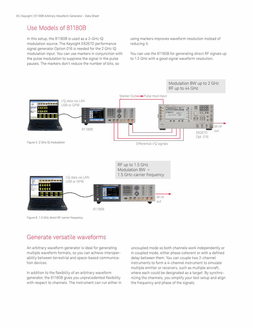
Generate versatile waveforms An arbitrary waveform generator is ideal for generating multiple waveform formats, so you can achieve interoper-ability between terrestrial and space-based communica-tion devices.
In addition to the flexibility of an arbitrary waveform generator, the 81180B gives you unprecedented flexibility with respect to channels. The instrument can run either in
Figure 5. 2 GHz IQ modulation
Figure 6. 1.5 GHz direct RF carrier frequency
Modulation BW up to 2 GHz RF up to 44 GHz
RF up to 1.5 GHzModulation BW =1.5 GHz-carrier frequency
uncoupled mode so both channels work independently or in coupled mode, either phase coherent or with a defined delay between them. You can couple two 2-channel instruments to form a 4-channel instrument to simulate multiple emitter or receivers, such as multiple aircraft, where each could be designated as a target. By synchro-nizing the channels, you simplify your test setup and align the frequency and phase of the signals.
Use Models of 81180B
In this setup, the 81180B is used as a 2-GHz IQ modulation source. The Keysight E8267D performance signal generator Option 016 is needed for the 2 GHz IQ modulation input. You can use markers in conjunction with the pulse modulation to suppress the signal in the pulse pauses. The markers don’t reduce the number of bits, so
using markers improves waveform resolution instead of reducing it.
You can use the 81180B for generating direct RF signals up to 1.5 GHz with a good signal waveform resolution.
I/Q data via LANUSB or GPIB
81180B
Differential I/Q signals
Marker Out Pulse mod input
E8267D Opt. 016
RF/IFout
RF/IFout
81180B
I/Q data via LANUSB or GPIB
05 | Keysight | 81180B Arbitrary Waveform Generator - Data Sheet

Choose the Best Amplifier to Optimize Your Signal Characteristics
Optimized for direct RF/IF applications
Bandwidth (MHz)1600
1400
1200
1000
800
600
400
200
0
Optimized forpurest signal in I/Q applicationswith a vector PSG
Time domainDC amp
Maximum bandwidth
RF amp Direct DACIQ applications
Optimized for time domain applications
1 GHz per channel = 2 GHz I/Q modulation BW
Different applications call for different signal characteristics. You can choose from three different amplifiers with different characteristics. You can switch between the amplifiers using your software application, the programming interface or the instrument’s front panel.
Figure 7.
Figure 8.
81180B AWG with 3 optional amplifiers
Optimized for different signal characteristics
jitterMaximum bandwidth
1.5 GHz
Time domain measurements
Low jitter
Time domain measurements
Low jitter
06 | Keysight | 81180B Arbitrary Waveform Generator - Data Sheet
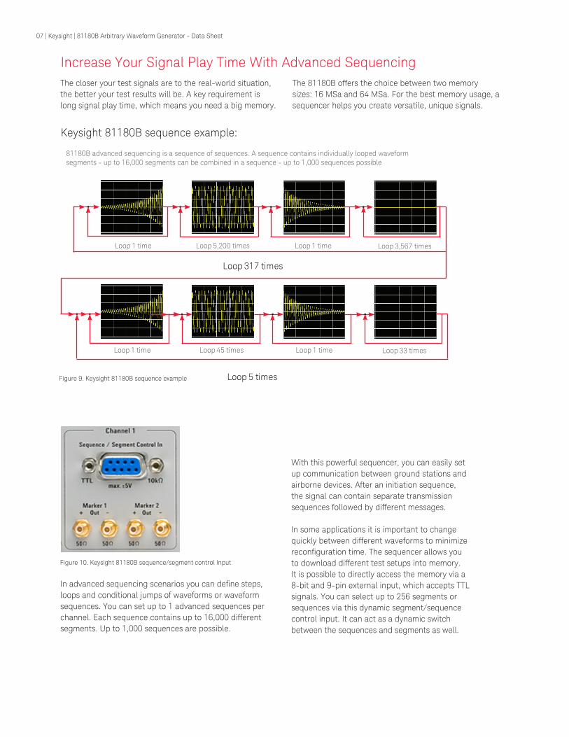
The closer your test signals are to the real-world situation, the better your test results will be. A key requirement is long signal play time, which means you need a big memory.
Loop 1 time Loop 5,200 times Loop 1 time Loop 3,567 times
Loop 317 times
Loop 1 time Loop 45 times Loop 1 time Loop 33 times
Loop 5 times
81180B advanced sequencing is a sequence of sequences. A sequence contains individually looped waveform segments - up to 16,000 segments can be combined in a sequence - up to 1,000 sequences possible
In advanced sequencing scenarios you can define steps, loops and conditional jumps of waveforms or waveform sequences. You can set up to 1 advanced sequences per channel. Each sequence contains up to 16,000 different segments. Up to 1,000 sequences are possible.
Figure 10. Keysight 81180B sequence/segment control Input
The 81180B offers the choice between two memory sizes: 16 MSa and 64 MSa. For the best memory usage, a sequencer helps you create versatile, unique signals.
Keysight 81180B sequence example:
Increase Your Signal Play Time With Advanced Sequencing
With this powerful sequencer, you can easily set up communication between ground stations and airborne devices. After an initiation sequence, the signal can contain separate transmission sequences followed by different messages.
In some applications it is important to change quickly between different waveforms to minimize reconfiguration time. The sequencer allows you to download different test setups into memory. It is possible to directly access the memory via a 8-bit and 9-pin external input, which accepts TTL signals. You can select up to 256 segments or sequences via this dynamic segment/sequence control input. It can act as a dynamic switch between the sequences and segments as well.
Figure 9. Keysight 81180B sequence example
07 | Keysight | 81180B Arbitrary Waveform Generator - Data Sheet

Create Complex Signals in a Variety of Software Environments
Figure 11.
You can choose between tools like MATLAB software, NI LabVIEW and Visual Studio with IVI or Keysight waveform creation tools like Keysight BenchLink Waveform Builder Pro and Keysight wideband waveform center.
With the optional BenchLink Waveform Builder Pro you can simply create custom, user-defined waveforms and import other waveforms from MATLAB and oscilloscopes measurements.
You can easily set up simple waveforms like sine waves, pulses, or ramps from the front panel of the 81180B. Complex modulation or arbitrary waveforms require waveform creation tools to create realistic signals.
Keysight BenchLink Waveform Builder Pro
81199A Keysight Wideband Waveform Center
Visual Studio plus IVI Foundation
LabVIEWMatlab
08 | Keysight | 81180B Arbitrary Waveform Generator - Data Sheet

Figure 12. Multi-tone signal on spectrum analyzer. 20 tones spanning ± 25 MHz around 300 MHz, Fs = 4.2 GS/s, IMD: –68 dB
Figure 13. Radar pulse with 2 GHz bandwidth. Radar pulse with 2 GHz
bandwidth
MATLAB scipt examples are available on www.keysight.com/find/81180_demo and will give you a jumpstart to generate multi-tone signals, pulsed radar signals and multi-carrier modulated waveforms using the 81180 – standalone or in conjunction with a Vector PSG.
Analysis of Radar Pulse on Scope With VSA Software
09 | Keysight | 81180B Arbitrary Waveform Generator - Data Sheet

Electrical Specifications
Instrument configuration
Characteristics Description
81180B 4.6-GSa/s arbitrary waveform generator with three output paths, DC-coupled direct DAC output with 1 GHz bandwidth, DC-coupled 2-V amplifier with > 600 MHz analog bandwidth or, AC-coupled 10 dBm amplifier with 1.5 GHz analog bandwidth
81180B-216 Dual-channel instrument with 16,000,000 waveform points
81180B-264 Dual-channel instrument with 64,000,000 waveform points
81180A-F4G Reconstruction filter
81180A-1CN Rack mounting kit assembly
81180A-SYN Synchronization cable to synchronize two dual-channel 81180Bs to form a four-channel 4.6-GSa/s arbitrary waveform generator system
Interchannel offset control (Course tuning )
Characteristics Description
Initial skew < 200 ps from 1 GSa/s to 4.6 GSa/s; < 1 ns from 100 MSa/s to 1 GSa/s; < 10 ns below 100 MSa/s
Control
Range 0 to segment length; 0 to 80 points with external segment control (n = segment length)
Resolution 8 points
Accuracy Same as sample clock accuracy
Interchannel skew control (Fine tuning )
Characteristics Description
Initial skew < 200 ps from 1 GSa/s to 4.6 GSa/s; < 1 ns from 100 MSa/s to 1 GSa/s; < 10 ns below 100 MSa/s
Control
Range (Skew is added to offset) –3 ns to + 3 ns
Resolution 10 ps
Accuracy ± (10% of setting + 20 ps)
10 | Keysight | 81180B Arbitrary Waveform Generator - Data Sheet

Waveform type
Characteristics DescriptionStandard A waveform is selected from a built-in library. The standard waveform parameters are
programmable.
Arbitrary Arbitrary waveform coordinates are downloaded and stored in memory segments. The arbitrary waveform parameters are programmable.
Sequenced Arbitrary waveforms are downloaded and stored in memory segments. The segments are arranged in a sequence table that step, loop, jump and nest on segments in a user-defined configuration. Conditional jump and nest pending an event signal.
Advanced sequences Same functionality as described for sequenced waveforms except sequences are arranged in the sequence table.
Modulated A modulated waveform is calculated from a built-in library of modulation schemes.
Pulse A pulse waveform is calculated and downloaded to the arbitrary waveform memory.
Run mode
Characteristics Description
Continuous
Self armed A selected output function shape is output continuously. No start commands are required to generate waveforms.
Armed The output dwells on dc level and waits for an enable command and then the output waveform is output continuously; an abort command turns off the waveform.
Triggered A trigger signal activates a single-shot or counted burst of output waveforms and then the instrument waits for the next trigger signal.
Normal mode The first trigger signal activates the output; consecutive triggers are ignored for the duration of the output waveform.
Override mode The first trigger signal activates the output; consecutive triggers restart the output waveform whether the current waveform has been completed or not.
Gated A waveform is output when a gate signal is asserted. The waveform is repeated until the gate signal is de-asserted. Last period is always completed.
Standard waveforms
Characteristics Description
General Waveforms are computed and generated every time a standard waveform is selected.
Standard waveform library Built-in, auto computed waveforms: sine, triangle, square, ramp, pulse, sink, exponential rise, exponential decay, Gaussian, noise and DC.
Standard waveform control The standard waveform parameters can be adjusted to specific requirements. The waveform is recomputed with each parameter change.
Electrical Specifications (continued)
11 | Keysight | 81180B Arbitrary Waveform Generator - Data Sheet

Standard waveforms frequency control
Characteristics Description
Range 10 kHz to 250 MHz
Resolution 8 digits
Accuracy
Internal reference ≤ 1 ppm from 19 ºC to 29 ºC; 1 ppm/ºC below 19 ºC or above 29 ºC; ≤ 1 ppm/year aging rate
External reference Same as accuracy and stability of the external reference. Reference is applied to the reference input.
Arbitrary waveforms
Characteristics Description
General Arbitrary waveforms are created on a remote computer and downloaded to the arbitrary waveform memory through one of the available remote interfaces. The frequency of the waveform is calculated from its programmed sample clock value and the number of waveform points that were used for creating the waveform.
Waveform length 384 to 16,000,000 points (384 to 64,000,000 with Option (264), in multiples of 32 points
Number of waveforms 1 to 16,000
Dynamic waveform control Software command or rear-panel segment control input (D-sub, 8-bit lines)
Waveform jump timing Coherent or asynchronous, selectable
DAC resolution 12 bits
Sequenced waveforms
Characteristics Description
General Segments are grouped in a sequence table that links, loops and jumps to next in user-defined scenarios. Sequence steps are advanced on trigger events or remote commands. Each channel has its own sequence scenario.
Sequence scenario 1 to 1,000 unique scenarios, programmed in sequence tables
Sequence table length 3 to 49,152 steps
Step advance control Auto, once (x “N”) and stepped
Loop counter
Segment loops 1 to 16,000,000 cycles, each segment
Sequence loops 1 to 1,000,000 (applies to “Once” sequence advance mode only)
Electrical Specifications (continued)
12 | Keysight | 81180B Arbitrary Waveform Generator - Data Sheet
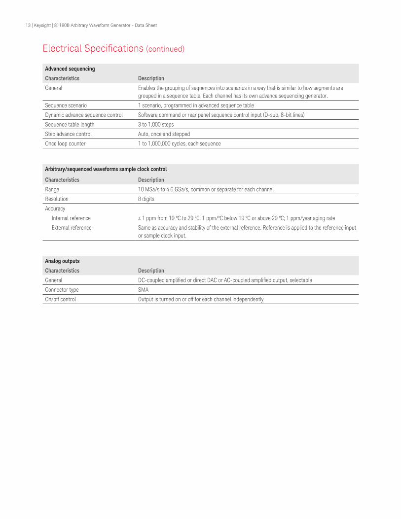
Advanced sequencing
Characteristics Description
General Enables the grouping of sequences into scenarios in a way that is similar to how segments are grouped in a sequence table. Each channel has its own advance sequencing generator.
Sequence scenario 1 scenario, programmed in advanced sequence table
Dynamic advance sequence control Software command or rear panel sequence control input (D-sub, 8-bit lines)
Sequence table length 3 to 1,000 steps
Step advance control Auto, once and stepped
Once loop counter 1 to 1,000,000 cycles, each sequence
Arbitrary/sequenced waveforms sample clock control
Characteristics Description
Range 10 MSa/s to 4.6 GSa/s, common or separate for each channel
Resolution 8 digits
Accuracy
Internal reference ≤ 1 ppm from 19 ºC to 29 ºC; 1 ppm/ºC below 19 ºC or above 29 ºC; 1 ppm/year aging rate
External reference Same as accuracy and stability of the external reference. Reference is applied to the reference input or sample clock input.
Analog outputs
Characteristics Description
General DC-coupled amplified or direct DAC or AC-coupled amplified output, selectable
Connector type SMA
On/off control Output is turned on or off for each channel independently
Electrical Specifications (continued)
13 | Keysight | 81180B Arbitrary Waveform Generator - Data Sheet
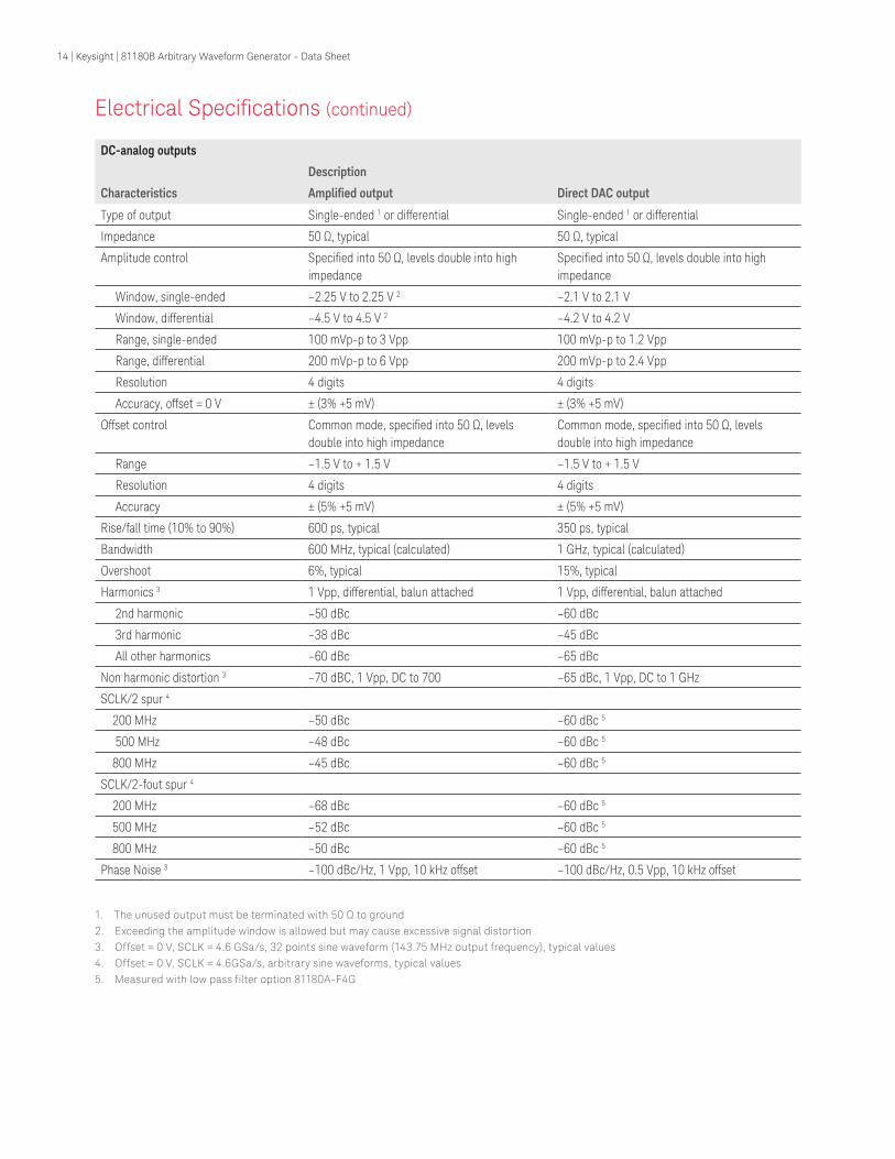
DC-analog outputs
Description
Characteristics Amplified output Direct DAC output
Type of output Single-ended 1 or differential Single-ended 1 or differential
Impedance 50 Ω, typical 50 Ω, typical
Amplitude control Specified into 50 Ω, levels double into high impedance
Specified into 50 Ω, levels double into high impedance
Window, single-ended –2.25 V to 2.25 V 2 –2.1 V to 2.1 V
Window, differential –4.5 V to 4.5 V 2 –4.2 V to 4.2 V
Range, single-ended 100 mVp-p to 3 Vpp 100 mVp-p to 1.2 Vpp
Range, differential 200 mVp-p to 6 Vpp 200 mVp-p to 2.4 Vpp
Resolution 4 digits 4 digits
Accuracy, offset = 0 V ± (3% +5 mV) ± (3% +5 mV)
Offset control Common mode, specified into 50 Ω, levels double into high impedance
Common mode, specified into 50 Ω, levels double into high impedance
Range –1.5 V to + 1.5 V –1.5 V to + 1.5 V
Resolution 4 digits 4 digits
Accuracy ± (5% +5 mV) ± (5% +5 mV)
Rise/fall time (10% to 90%) 600 ps, typical 350 ps, typical
Bandwidth 600 MHz, typical (calculated) 1 GHz, typical (calculated)
Overshoot 6%, typical 15%, typical
Harmonics 3 1 Vpp, differential, balun attached 1 Vpp, differential, balun attached
2nd harmonic –50 dBc –60 dBc
3rd harmonic –38 dBc –45 dBc
All other harmonics –60 dBc –65 dBc
Non harmonic distortion 3 –70 dBC, 1 Vpp, DC to 700 –65 dBc, 1 Vpp, DC to 1 GHz
SCLK/2 spur 4
200 MHz –50 dBc –60 dBc 5
500 MHz –48 dBc –60 dBc 5
800 MHz –45 dBc –60 dBc 5
SCLK/2-fout spur 4
200 MHz –68 dBc –60 dBc 5
500 MHz –52 dBc –60 dBc 5
800 MHz –50 dBc –60 dBc 5
Phase Noise 3 –100 dBc/Hz, 1 Vpp, 10 kHz offset –100 dBc/Hz, 0.5 Vpp, 10 kHz offset
1. The unused output must be terminated with 50 Ω to ground2. Exceeding the amplitude window is allowed but may cause excessive signal distortion3. Offset = 0 V, SCLK = 4.6 GSa/s, 32 points sine waveform (143.75 MHz output frequency), typical values4. Offset = 0 V, SCLK = 4.6GSa/s, arbitrary sine waveforms, typical values5. Measured with low pass filter option 81180A-F4G
Electrical Specifications (continued)
14 | Keysight | 81180B Arbitrary Waveform Generator - Data Sheet

RF, AC-coupled analog output
Characteristics Description
Type of output Single-ended 1
Impedance 50 Ω, typical
Amplitude control Specified into 50 Ω, levels double into high impedance
Range –20 dBm to 10 dBm
Resolution 4 digits
Accuracy ±(3% +0.5 dBm)
Bandwidth 1.5 GHz, typical
Flatness ±1.2 dB 4 MHz to 1 GHz, ±2 dB 1 GHz to 1.5 GHz, typical
Harmonics 2
2nd harmonic –60 dBc
3rd harmonic –38 dBc
All other haromics –60 dBc
Nonharmonic distortion 2 –60 dBc, DC to 1.5 GHz
SCLK/2 spur 3
200 MHz –68 dBc 4
500 MHz –68 dBc 4
800 MHz –68 dBc 4
SCLK/2-fout spur 3
200 MHz –68 dBc 4
500 MHz –68 dBc 4
800 MHz –60 dBc 4
Phase noise 2 –100 dBc/Hz, 10 kHz offset
1. The unused output can be left open2. SCLK = 4.6 GSa/s, 32 points sine waveform (143.75 MHz output frequency), typical values3. SCLK = 4.6 GSa/s, arbitrary sine waveforms, typical values,0 dBm4. Measured with low pass filter option 81180A-F4G
Electrical Specifications (continued)
15 | Keysight | 81180B Arbitrary Waveform Generator - Data Sheet

Marker outputs
Characteristics Description
Connector type SMB
Number of markers Two markers per channel
Type of output Differential (+) and (–) outputs
Impedance 50 Ω, typical
Level control Specified into 50 Ω, levels double into high impedance
Voltage window 0 V to 1.25 V, single-ended; 0 V to 2.5 V, differential
Low level 0 V to 0.8 V, single-ended; 0 V to 1.6 V, differential
High level 0.5 V to 1.25 V, single-ended; 1 V to 2.5 V, differential
Resolution 10 mV
Accuracy 10% of setting
Width control 0 SCLK periods to segment length
Position control 0 to segment length in 4 point increments
Marker resolution 4 SCLK periods (programmed as part of the output waveform)
Initial delay 1 3.5 ns, +1 sample clock period, typical
Initial skew between marker 1 and marker 2
< 100 ps, typical
Variable delay control Separate for each marker
Range 0 to 3 ns
Resolution 10 ps
Accuracy ± (10% of setting +20 ps)
Rise/fall time 1.0 ns, typical
1. Analog output to marker output
SYNC output
Characteristics Description
Connector type SMA
Type of output Single ended
Source Channel 1 or channel 2
Waveform Pulse (32 points width), WCOM (waveform duration pulse)
Impedance 50 Ω, typical
Amplitude 1.2 V, typical; doubles into high impedance
Variable position control
Range 0 to segment length
Resolution 32 points
Rise/fall time 2 ns, typical
Variable width control
Range 32 points to segment length
Resolution 32 points
Electrical Specifications (continued)
16 | Keysight | 81180B Arbitrary Waveform Generator - Data Sheet

Trigger input
Characteristics Description
Connector type SMA
Drive Channel 1, channel 2, or both
Input impedance 10 kΩ, typical
Polarity Positive, negative, or both, selectable
Damage level ± 20 Vdc
Frequency range 0 to 15 MHz
Trigger level control
Range –5 V to 5 V
Resolution 12 bit (2.5 mV)
Accuracy ± (5% of setting + 2.5 mV)
Sensitivity 200 mVp-p
Pulse width, minimum 10 ns
System delay 1 200 sample clock periods + 50 ns, typical
Trigger delay Separate for each channel
Range 0 to 8,000,000 sample clock periods
Resolution 8 points
Accuracy Same as sample clock accuracy
Smart trigger Detects a unique pulse width range
Conditioned trigger < pulse width, > pulse width, <> pulse width
Pulse width range 50 ns to 2 s
Resolution 2 ns
Accuracy ± (5% of setting +20 ns)
Trigger holdoff Ignores triggers for a holdoff duration
Holdoff range 100 ns to 2 s
Resolution 2 ns
Accuracy ± (5% of setting +20 ns)
Internal trigger generator
Characteristics Description
Source Common or separate for each channel
Mode Timer (waveform start to waveform start); delayed (waveform stop to waveform start)
Timer
Range 100 ns to 2 s
Resolution 3 digits
Accuracy 100 ppm
Delayed
Range 152 to 8,000,000 sample clock periods
Resolution Integer numbers, divisible by 8
Electrical Specifications (continued)
17 | Keysight | 81180B Arbitrary Waveform Generator - Data Sheet

Event input
Characteristics Description
General Used for branching in or out from a sequence loop. Also used for enabling or disabling the output in armed mode.
Connector type Rear panel BNC
Input impedance 10 kΩ, typical
Polarity Positive, negative or either, selectable
Damage level ± 20 Vdc
Frequency range 0 to 15 MHz
Trigger level control
Range –5 V to 5 V
Resolution 12 bit (2.5 mV)
Accuracy ± (5% of setting + 2.5 mV)
Sensitivity 200 mVp-p
Pulse width, minimum 10 ns
Sequence/segment control input
Characteristics Description
Connector type D-sub, 8-bit lines
Number of input connectors 1-ch instrument: 8-bit bus + valid line
2-ch instrument: (8-bit bus + valid line) per channel
Switching rate 20 ns + waveform duration minimum
Input impedance 10 kΩ, typical
Input level TTL
External reference clock input
Characteristics Description
Connector type Rear panel BNC
Input frequency 10 MHz to 100 MHz 1, programmable
Input impedance 50 Ω, typical
Input voltage swing –5 dBm to 5 dBm
Damage level 10 dBm
1. An exact frequency ratio between reference clock input and the internally generated sample clock is available only, for ratios of 2, 4, 8, 16, 32, 64, 125, 256
Electrical Specifications (continued)
18 | Keysight | 81180B Arbitrary Waveform Generator - Data Sheet

External sample clock input
Characteristics Description
General External signal is fed to a frequency splitter. Same frequency is applied to both channels.
Connector type Rear-panel SMA
Input impedance 50 Ω, typical
Input voltage swing 0 dBm to 10 dBm
Input frequency range 2.0 GHz to 4.6 GHz
Clock divider 1/1, 1/2, 1/4, … 1/ 256, separate for each channel
Damage level 15 dBm
Two-instrument synchronization
Characteristics Description
General Two instruments are synchronized via dedicated synchronization cable. Master instrument controls waveform generation of slave instrument.
Initial skew between instruments 20 ns + 0 to 16 SCLK periods
Offset control range 0 to waveform length; 0 to 80 points with external segment control
Offset resolution 8 SCLK periods increments
Skew control range –5 ns to 5 ns (skew is added to offset)
Skew resolution 10 ps
Clock source Master sample clock generator
Trigger source Master trigger input
Display
Characteristics Description
Type TFT LCD, back-lit
Size 4 “
Resolution 320 x 240 pixels
Peripheral devices
Characteristics Description
USB port 1 x front, USB host, standard A; 1 x rear, USB device, standard B
LAN port 1000/100/10 BASE-T
GPIB port IEEE 488.2 standard interface, 24 pin
Segment control port 2 x D-sub, 9 pin
Mechanical, Environmental and Maintenance Specifications
Electrical Specifications (continued)
19 | Keysight | 81180B Arbitrary Waveform Generator - Data Sheet

Power supply
Characteristics Description
Source voltage and frequency
Rating range 100 VAC to 240 VAC
Frequency range 50 Hz to 60 Hz
Power consumption 100 VA
Sequence/segment control input
Characteristics Description
Dimensions
With feet 315 x 102 x 395 mm (W x H x D)
Without feet 315 x 88 x 395 mm (W x H x D)
Weight
Without package 4.5 kg
Shipping weight 6 kg
Environmental
Characteristics Description
Operating temperature 0 ºC to 40 ºC
Storage temperature –40 ºC to 70 ºC
Humidity 85% RH, non condensing
Certifications and compliances
Characteristics Description
Safety IEC61010-1
EMC IEC 61326-1:2006
Maintenancel
Characteristics Description
General Periodic recalibration is required to maintain accuracy of output characteristics
Recalibration period 2 years
Mechanical, Environmental and Maintenance Specifications (continued)
20 | Keysight | 81180B Arbitrary Waveform Generator - Data Sheet

21 | Keysight | 81180B Arbitrary Waveform Generator - Data Sheet
This information is subject to change without notice.© Keysight Technologies, 2017Published in USA, December 1, 20175991-0364ENwww.keysight.com
www.keysight.com/find/81180www.keysight.com/find/81180_demo
For more information on Keysight Technologies’ products, applications or services, please contact your local Keysight office. The complete list is available at:www.keysight.com/find/contactus
Americas Canada (877) 894 4414Brazil 55 11 3351 7010Mexico 001 800 254 2440United States (800) 829 4444
Asia PacificAustralia 1 800 629 485China 800 810 0189Hong Kong 800 938 693India 1 800 11 2626Japan 0120 (421) 345Korea 080 769 0800Malaysia 1 800 888 848Singapore 1 800 375 8100Taiwan 0800 047 866Other AP Countries (65) 6375 8100
Europe & Middle EastAustria 0800 001122Belgium 0800 58580Finland 0800 523252France 0805 980333Germany 0800 6270999Ireland 1800 832700Israel 1 809 343051Italy 800 599100Luxembourg +32 800 58580Netherlands 0800 0233200Russia 8800 5009286Spain 800 000154Sweden 0200 882255Switzerland 0800 805353
Opt. 1 (DE)Opt. 2 (FR)Opt. 3 (IT)
United Kingdom 0800 0260637
For other unlisted countries:www.keysight.com/find/contactus(BP-9-7-17)
DEKRA CertifiedISO9001 Quality Management System
www.keysight.com/go/qualityKeysight Technologies, Inc.DEKRA Certified ISO 9001:2015Quality Management System
Evolving Since 1939Our unique combination of hardware, software, services, and people can help you reach your next breakthrough. We are unlocking the future of technology. From Hewlett-Packard to Agilent to Keysight.
myKeysightwww.keysight.com/find/mykeysightA personalized view into the information most relevant to you.
http://www.keysight.com/find/emt_product_registrationRegister your products to get up-to-date product information and find warranty information.
Keysight Serviceswww.keysight.com/find/serviceKeysight Services can help from acquisition to renewal across your instrument’s lifecycle. Our comprehensive service offerings—one-stop calibration, repair, asset management, technology refresh, consulting, training and more—helps you improve product quality and lower costs.
Keysight Assurance Planswww.keysight.com/find/AssurancePlansUp to ten years of protection and no budgetary surprises to ensure your instruments are operating to specification, so you can rely on accurate measurements.
Keysight Channel Partnerswww.keysight.com/find/channelpartnersGet the best of both worlds: Keysight’s measurement expertise and product breadth, combined with channel partner convenience.