keysight technologies b1530a waveform …literature.cdn.keysight.com/litweb/pdf/b1530-90000.pdfin...
TRANSCRIPT

Keysight Technologies B1530A Waveform Generator/Fast Measurement Unit
User’s Guide
NoticesCopyright Notice© Keysight Technologies 2008-2015
No part of this manual may be reproduced in any form or by any means (including elec-tronic storage and retrieval or translation into a foreign language) without prior agreement and written consent from Keysight Technolo-gies as governed by United States and inter-national copyright laws.
Manual Part NumberB1530-90000
EditionEdition 1, September 2008Edition 2, February 2009Edition 3, October 2009Edition 4, June 2011Edition 5, August 2012Edition 6, August 2014Edition 7, June 2015
Printed in:Printed in Malaysia
Published by:Keysight Technologies, Inc.1400 Fountaingrove Parkway Santa Rosa, CA 95403 USA
Technology Licenses The hardware and/or software described in this document are furnished under a license and may be used or copied only in accordance with the terms of such license.
Declaration of ConformityDeclarations of Conformity for this product and for other Keysight products may be downloaded from the Web. Go to http://www.keysight.com/go/conformity and click on “Declarations of Conformity.” You can then search by product number to find the latest Declaration of Conformity.
U.S. Government RightsThe Software is “commercial computer soft-ware,” as defined by Federal Acquisition Reg-ulation (“FAR”) 2.101. Pursuant to FAR 12.212 and 27.405-3 and Department of Defense FAR Supplement (“DFARS”) 227.7202, the U.S. government acquires commercial computer software under the same terms by which the software is customarily provided to the public. Accordingly, Keysight provides the Software to U.S. government customers under its stan-dard commercial license, which is embodied in its End User License Agreement (EULA), a copy of which can be found at http://www.keysight.com/find/sweula. The license set forth in the EULA represents the exclusive authority by which the U.S. government may use, modify, distribute, or disclose the Soft-ware. The EULA and the license set forth therein, does not require or permit, among other things, that Keysight: (1) Furnish techni-cal information related to commercial com-puter software or commercial computer software documentation that is not customar-ily provided to the public; or (2) Relinquish to, or otherwise provide, the government rights in excess of these rights customarily provided to the public to use, modify, reproduce, release, perform, display, or disclose com-mercial computer software or commercial computer software documentation. No addi-tional government requirements beyond those set forth in the EULA shall apply, except to the extent that those terms, rights, or licenses are explicitly required from all providers of com-mercial computer software pursuant to the FAR and the DFARS and are set forth specifi-cally in writing elsewhere in the EULA. Key-sight shall be under no obligation to update, revise or otherwise modify the Software. With respect to any technical data as defined by FAR 2.101, pursuant to FAR 12.211 and 27.404.2 and DFARS 227.7102, the U.S. gov-ernment acquires no greater than Limited Rights as defined in FAR 27.401 or DFAR 227.7103-5 (c), as applicable in any technical data.
WarrantyTHE MATERIAL CONTAINED IN THIS DOCU-MENT IS PROVIDED “AS IS,” AND IS SUBJECT TO BEING CHANGED, WITHOUT NOTICE, IN FUTURE EDITIONS. FURTHER, TO THE MAXI-MUM EXTENT PERMITTED BY APPLICABLE LAW, KEYSIGHT DISCLAIMS ALL WARRAN-TIES, EITHER EXPRESS OR IMPLIED, WITH REGARD TO THIS MANUAL AND ANY INFOR-MATION CONTAINED HEREIN, INCLUDING BUT NOT LIMITED TO THE IMPLIED WAR-RANTIES OF MERCHANTABILITY AND FIT-NESS FOR A PARTICULAR PURPOSE. KEYSIGHT SHALL NOT BE LIABLE FOR ERRORS OR FOR INCIDENTAL OR CONSE-QUENTIAL DAMAGES IN CONNECTION WITH THE FURNISHING, USE, OR PERFORMANCE OF THIS DOCUMENT OR OF ANY INFORMA-TION CONTAINED HEREIN. SHOULD KEY-SIGHT AND THE USER HAVE A SEPARATE WRITTEN AGREEMENT WITH WARRANTY TERMS COVERING THE MATERIAL IN THIS DOCUMENT THAT CONFLICT WITH THESE TERMS, THE WARRANTY TERMS IN THE SEP-ARATE AGREEMENT SHALL CONTROL.
Latest InformationTo get the latest firmware/software/electronic manuals/specifications/support information, go to www.keysight.com and type in the prod-uct number in the Search field at the top of the page.


This product complies with the WEEE Directive (2002/96/EC) marking requirements. The affixed label indicates that you must not discard this electrical/ electronic product in domestic household waste.
Product Category: With reference to the equipment types in the WEEE Directive Annex I, this product is classed as a “Monitoring and Control instrumentation” product.
Do not dispose in domestic household waste.
To return unwanted products, contact your local Keysight office or visit the following website for more information.
http://about.keysight.com/en/companyinfo/environment/
When Servicing B1530AWhen the B1530A needs any service, return it to your nearest Keysight Technologies. Then do not return the B1530A only. The following equipment and accessories are required for servicing.
• B1500A with all plug-in modules installed
• B1531A RSU
• Connection cable set
The connection cable set means one of the following.
• 16493R-003 3 m Cable between WGFMU and RSU
• 16493R-004 5 m Cable between WGFMU and RSU
• 16493R-006 1.5 m Cable between WGFMU and RSU
• 16493R-001 and 002 60 cm Cable and 2.4 m Cable between WGFMU and RSU
• 16493R-001 and 005 60 cm Cable and 4.4 m Cable between WGFMU and RSU
For more information, see Keysight B1500A manual.

In This Manual This manual provides the information about Keysight Technologies B1530A Waveform Generator/Fast Measurement Unit (WGFMU) and consists of the following chapters.
• Chapter 1, Introduction
Describes product overview of WGFMU.
• Chapter 2, Installation
Explains how to set up the measurement environment using WGFMU.
• Chapter 3, Using Instrument Library
Describes how to use the instrument library and provides programming examples.
• Chapter 4, Instrument Library Reference
Provides reference information of the instrument library designed for WGFMU.
NOTE For the specifications of the B1530A, see Data Sheet.
To get the latest Data Sheet, go to www.keysight.com/find/b1500a and click “Technical Support” and “Specifications”.
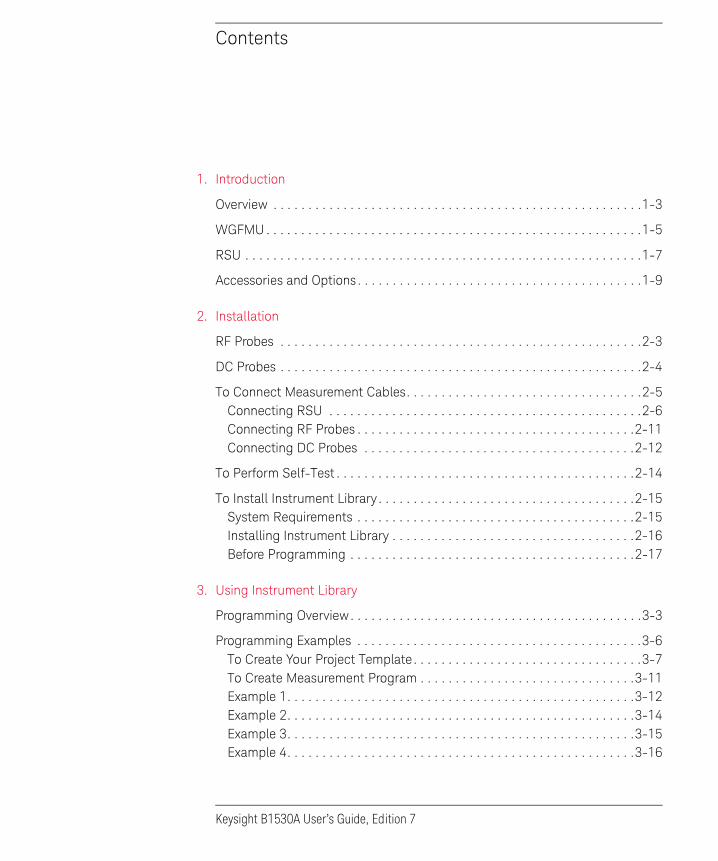
Contents
1. Introduction
Overview . . . . . . . . . . . . . . . . . . . . . . . . . . . . . . . . . . . . . . . . . . . . . . . . . . . . .1-3
WGFMU . . . . . . . . . . . . . . . . . . . . . . . . . . . . . . . . . . . . . . . . . . . . . . . . . . . . . .1-5
RSU . . . . . . . . . . . . . . . . . . . . . . . . . . . . . . . . . . . . . . . . . . . . . . . . . . . . . . . . .1-7
Accessories and Options . . . . . . . . . . . . . . . . . . . . . . . . . . . . . . . . . . . . . . . . .1-9
2. Installation
RF Probes . . . . . . . . . . . . . . . . . . . . . . . . . . . . . . . . . . . . . . . . . . . . . . . . . . . .2-3
DC Probes . . . . . . . . . . . . . . . . . . . . . . . . . . . . . . . . . . . . . . . . . . . . . . . . . . . .2-4
To Connect Measurement Cables. . . . . . . . . . . . . . . . . . . . . . . . . . . . . . . . . .2-5Connecting RSU . . . . . . . . . . . . . . . . . . . . . . . . . . . . . . . . . . . . . . . . . . . . .2-6Connecting RF Probes . . . . . . . . . . . . . . . . . . . . . . . . . . . . . . . . . . . . . . . .2-11Connecting DC Probes . . . . . . . . . . . . . . . . . . . . . . . . . . . . . . . . . . . . . . .2-12
To Perform Self-Test . . . . . . . . . . . . . . . . . . . . . . . . . . . . . . . . . . . . . . . . . . .2-14
To Install Instrument Library . . . . . . . . . . . . . . . . . . . . . . . . . . . . . . . . . . . . .2-15System Requirements . . . . . . . . . . . . . . . . . . . . . . . . . . . . . . . . . . . . . . . .2-15Installing Instrument Library . . . . . . . . . . . . . . . . . . . . . . . . . . . . . . . . . . .2-16Before Programming . . . . . . . . . . . . . . . . . . . . . . . . . . . . . . . . . . . . . . . . .2-17
3. Using Instrument Library
Programming Overview. . . . . . . . . . . . . . . . . . . . . . . . . . . . . . . . . . . . . . . . . .3-3
Programming Examples . . . . . . . . . . . . . . . . . . . . . . . . . . . . . . . . . . . . . . . . .3-6To Create Your Project Template. . . . . . . . . . . . . . . . . . . . . . . . . . . . . . . . .3-7To Create Measurement Program . . . . . . . . . . . . . . . . . . . . . . . . . . . . . . .3-11Example 1. . . . . . . . . . . . . . . . . . . . . . . . . . . . . . . . . . . . . . . . . . . . . . . . . .3-12Example 2. . . . . . . . . . . . . . . . . . . . . . . . . . . . . . . . . . . . . . . . . . . . . . . . . .3-14Example 3. . . . . . . . . . . . . . . . . . . . . . . . . . . . . . . . . . . . . . . . . . . . . . . . . .3-15Example 4. . . . . . . . . . . . . . . . . . . . . . . . . . . . . . . . . . . . . . . . . . . . . . . . . .3-16
Keysight B1530A User’s Guide, Edition 7

Contents
Example 5 . . . . . . . . . . . . . . . . . . . . . . . . . . . . . . . . . . . . . . . . . . . . . . . . . 3-17Example 6 . . . . . . . . . . . . . . . . . . . . . . . . . . . . . . . . . . . . . . . . . . . . . . . . . 3-18Example 7 . . . . . . . . . . . . . . . . . . . . . . . . . . . . . . . . . . . . . . . . . . . . . . . . . 3-21Example 8 . . . . . . . . . . . . . . . . . . . . . . . . . . . . . . . . . . . . . . . . . . . . . . . . . 3-22Example 9 . . . . . . . . . . . . . . . . . . . . . . . . . . . . . . . . . . . . . . . . . . . . . . . . . 3-23Example 10 . . . . . . . . . . . . . . . . . . . . . . . . . . . . . . . . . . . . . . . . . . . . . . . . 3-26Example 11 . . . . . . . . . . . . . . . . . . . . . . . . . . . . . . . . . . . . . . . . . . . . . . . . 3-28
If You Perform DC Measurement . . . . . . . . . . . . . . . . . . . . . . . . . . . . . . . . . 3-30
4. Instrument Library Reference
Function Reference . . . . . . . . . . . . . . . . . . . . . . . . . . . . . . . . . . . . . . . . . . . . 4-9WGFMU_abort . . . . . . . . . . . . . . . . . . . . . . . . . . . . . . . . . . . . . . . . . . . . . . 4-9WGFMU_abortChannel. . . . . . . . . . . . . . . . . . . . . . . . . . . . . . . . . . . . . . . . 4-9WGFMU_addSequence. . . . . . . . . . . . . . . . . . . . . . . . . . . . . . . . . . . . . . . . 4-9WGFMU_addSequences. . . . . . . . . . . . . . . . . . . . . . . . . . . . . . . . . . . . . . 4-10WGFMU_addVector . . . . . . . . . . . . . . . . . . . . . . . . . . . . . . . . . . . . . . . . . 4-12WGFMU_addVectors . . . . . . . . . . . . . . . . . . . . . . . . . . . . . . . . . . . . . . . . 4-13WGFMU_clear . . . . . . . . . . . . . . . . . . . . . . . . . . . . . . . . . . . . . . . . . . . . . . 4-14WGFMU_closeLogFile. . . . . . . . . . . . . . . . . . . . . . . . . . . . . . . . . . . . . . . . 4-14WGFMU_closeSession . . . . . . . . . . . . . . . . . . . . . . . . . . . . . . . . . . . . . . . 4-14WGFMU_connect . . . . . . . . . . . . . . . . . . . . . . . . . . . . . . . . . . . . . . . . . . . 4-15WGFMU_createMergedPattern . . . . . . . . . . . . . . . . . . . . . . . . . . . . . . . . 4-15WGFMU_createMultipliedPattern . . . . . . . . . . . . . . . . . . . . . . . . . . . . . . 4-16WGFMU_createOffsetPattern . . . . . . . . . . . . . . . . . . . . . . . . . . . . . . . . . . 4-17WGFMU_createPattern. . . . . . . . . . . . . . . . . . . . . . . . . . . . . . . . . . . . . . . 4-18WGFMU_dcforceVoltage . . . . . . . . . . . . . . . . . . . . . . . . . . . . . . . . . . . . . 4-19WGFMU_dcmeasureAveragedValue . . . . . . . . . . . . . . . . . . . . . . . . . . . . 4-19WGFMU_dcmeasureValue . . . . . . . . . . . . . . . . . . . . . . . . . . . . . . . . . . . . 4-20WGFMU_disconnect . . . . . . . . . . . . . . . . . . . . . . . . . . . . . . . . . . . . . . . . . 4-21WGFMU_doSelfCalibration. . . . . . . . . . . . . . . . . . . . . . . . . . . . . . . . . . . . 4-21WGFMU_doSelfTest . . . . . . . . . . . . . . . . . . . . . . . . . . . . . . . . . . . . . . . . . 4-22
Keysight B1530A User’s Guide, Edition 7

Contents
WGFMU_execute . . . . . . . . . . . . . . . . . . . . . . . . . . . . . . . . . . . . . . . . . . . .4-23WGFMU_exportAscii . . . . . . . . . . . . . . . . . . . . . . . . . . . . . . . . . . . . . . . . .4-23WGFMU_getChannelIds . . . . . . . . . . . . . . . . . . . . . . . . . . . . . . . . . . . . . .4-25WGFMU_getChannelIdSize . . . . . . . . . . . . . . . . . . . . . . . . . . . . . . . . . . . .4-25WGFMU_getChannelStatus . . . . . . . . . . . . . . . . . . . . . . . . . . . . . . . . . . .4-25WGFMU_getCompletedMeasureEventSize. . . . . . . . . . . . . . . . . . . . . . . .4-26WGFMU_getError. . . . . . . . . . . . . . . . . . . . . . . . . . . . . . . . . . . . . . . . . . . .4-27WGFMU_getErrorSize . . . . . . . . . . . . . . . . . . . . . . . . . . . . . . . . . . . . . . . .4-27WGFMU_getErrorSummary. . . . . . . . . . . . . . . . . . . . . . . . . . . . . . . . . . . .4-28WGFMU_getErrorSummarySize . . . . . . . . . . . . . . . . . . . . . . . . . . . . . . . .4-28WGFMU_getForceDelay . . . . . . . . . . . . . . . . . . . . . . . . . . . . . . . . . . . . . .4-29WGFMU_getForceValue . . . . . . . . . . . . . . . . . . . . . . . . . . . . . . . . . . . . . .4-29WGFMU_getForceValues. . . . . . . . . . . . . . . . . . . . . . . . . . . . . . . . . . . . . .4-30WGFMU_getForceValueSize . . . . . . . . . . . . . . . . . . . . . . . . . . . . . . . . . . .4-31WGFMU_getForceVoltageRange . . . . . . . . . . . . . . . . . . . . . . . . . . . . . . .4-31WGFMU_getInterpolatedForceValue . . . . . . . . . . . . . . . . . . . . . . . . . . . .4-31WGFMU_getMeasureCurrentRange . . . . . . . . . . . . . . . . . . . . . . . . . . . . .4-32WGFMU_getMeasureDelay . . . . . . . . . . . . . . . . . . . . . . . . . . . . . . . . . . . .4-32WGFMU_getMeasureEvent . . . . . . . . . . . . . . . . . . . . . . . . . . . . . . . . . . . .4-33WGFMU_getMeasureEventAttribute . . . . . . . . . . . . . . . . . . . . . . . . . . . . .4-34WGFMU_getMeasureEvents . . . . . . . . . . . . . . . . . . . . . . . . . . . . . . . . . . .4-35WGFMU_getMeasureEventSize. . . . . . . . . . . . . . . . . . . . . . . . . . . . . . . . .4-37WGFMU_getMeasureMode . . . . . . . . . . . . . . . . . . . . . . . . . . . . . . . . . . . .4-38WGFMU_getMeasureTime. . . . . . . . . . . . . . . . . . . . . . . . . . . . . . . . . . . . .4-38WGFMU_getMeasureTimes . . . . . . . . . . . . . . . . . . . . . . . . . . . . . . . . . . . .4-39WGFMU_getMeasureTimeSize . . . . . . . . . . . . . . . . . . . . . . . . . . . . . . . . .4-40WGFMU_getMeasueValue. . . . . . . . . . . . . . . . . . . . . . . . . . . . . . . . . . . . .4-40WGFMU_getMeasureValues . . . . . . . . . . . . . . . . . . . . . . . . . . . . . . . . . . .4-41WGFMU_getMeasureValueSize. . . . . . . . . . . . . . . . . . . . . . . . . . . . . . . . .4-42WGFMU_getMeasureVoltageRange . . . . . . . . . . . . . . . . . . . . . . . . . . . . .4-42WGFMU_getOperationMode . . . . . . . . . . . . . . . . . . . . . . . . . . . . . . . . . . .4-43WGFMU_getPatternForceValue . . . . . . . . . . . . . . . . . . . . . . . . . . . . . . . .4-43
Keysight B1530A User’s Guide, Edition 7

Contents
WGFMU_getPatternForceValues . . . . . . . . . . . . . . . . . . . . . . . . . . . . . . . 4-44WGFMU_getPatternForceValueSize. . . . . . . . . . . . . . . . . . . . . . . . . . . . . 4-44WGFMU_getPatternInterpolatedForceValue . . . . . . . . . . . . . . . . . . . . . . 4-45WGFMU_getPatternMeasureTime . . . . . . . . . . . . . . . . . . . . . . . . . . . . . . 4-45WGFMU_getPatternMeasureTimes . . . . . . . . . . . . . . . . . . . . . . . . . . . . . 4-46WGFMU_getPatternMeasureTimeSize . . . . . . . . . . . . . . . . . . . . . . . . . . . 4-47WGFMU_getStatus . . . . . . . . . . . . . . . . . . . . . . . . . . . . . . . . . . . . . . . . . . 4-47WGFMU_getTriggerOutMode. . . . . . . . . . . . . . . . . . . . . . . . . . . . . . . . . . 4-48WGFMU_getWarningLevel . . . . . . . . . . . . . . . . . . . . . . . . . . . . . . . . . . . . 4-48WGFMU_getWarningSummary . . . . . . . . . . . . . . . . . . . . . . . . . . . . . . . . 4-49WGFMU_getWarningSummarySize . . . . . . . . . . . . . . . . . . . . . . . . . . . . . 4-49WGFMU_initialize . . . . . . . . . . . . . . . . . . . . . . . . . . . . . . . . . . . . . . . . . . . 4-50WGFMU_isMeasureEnabled . . . . . . . . . . . . . . . . . . . . . . . . . . . . . . . . . . . 4-50WGFMU_isMeasureEventCompleted . . . . . . . . . . . . . . . . . . . . . . . . . . . . 4-50WGFMU_openLogFile . . . . . . . . . . . . . . . . . . . . . . . . . . . . . . . . . . . . . . . . 4-51WGFMU_openSession . . . . . . . . . . . . . . . . . . . . . . . . . . . . . . . . . . . . . . . 4-52WGFMU_setForceDelay . . . . . . . . . . . . . . . . . . . . . . . . . . . . . . . . . . . . . . 4-52WGFMU_setForceVoltageRange . . . . . . . . . . . . . . . . . . . . . . . . . . . . . . . 4-53WGFMU_setMeasureCurrentRange . . . . . . . . . . . . . . . . . . . . . . . . . . . . . 4-53WGFMU_setMeasureDelay . . . . . . . . . . . . . . . . . . . . . . . . . . . . . . . . . . . . 4-54WGFMU_setMeasureEnabled. . . . . . . . . . . . . . . . . . . . . . . . . . . . . . . . . . 4-54WGFMU_setMeasureEvent . . . . . . . . . . . . . . . . . . . . . . . . . . . . . . . . . . . . 4-55WGFMU_setMeasureMode. . . . . . . . . . . . . . . . . . . . . . . . . . . . . . . . . . . . 4-56WGFMU_setMeasureVoltageRange. . . . . . . . . . . . . . . . . . . . . . . . . . . . . 4-57WGFMU_setOperationMode. . . . . . . . . . . . . . . . . . . . . . . . . . . . . . . . . . . 4-57WGFMU_setRangeEvent . . . . . . . . . . . . . . . . . . . . . . . . . . . . . . . . . . . . . 4-58WGFMU_setTimeout. . . . . . . . . . . . . . . . . . . . . . . . . . . . . . . . . . . . . . . . . 4-59WGFMU_setTriggerOutEvent . . . . . . . . . . . . . . . . . . . . . . . . . . . . . . . . . . 4-59WGFMU_setTriggerOutMode . . . . . . . . . . . . . . . . . . . . . . . . . . . . . . . . . . 4-60WGFMU_setVector . . . . . . . . . . . . . . . . . . . . . . . . . . . . . . . . . . . . . . . . . . 4-61WGFMU_setVectors . . . . . . . . . . . . . . . . . . . . . . . . . . . . . . . . . . . . . . . . . 4-62WGFMU_setWarningLevel . . . . . . . . . . . . . . . . . . . . . . . . . . . . . . . . . . . . 4-63
Keysight B1530A User’s Guide, Edition 7

Contents
WGFMU_treatWarningsAsErrors . . . . . . . . . . . . . . . . . . . . . . . . . . . . . . . .4-63WGFMU_update . . . . . . . . . . . . . . . . . . . . . . . . . . . . . . . . . . . . . . . . . . . .4-64WGFMU_updateChannel. . . . . . . . . . . . . . . . . . . . . . . . . . . . . . . . . . . . . .4-64WGFMU_waitUntilCompleted . . . . . . . . . . . . . . . . . . . . . . . . . . . . . . . . . .4-65
Parameters . . . . . . . . . . . . . . . . . . . . . . . . . . . . . . . . . . . . . . . . . . . . . . . . . .4-66
Channel Execution Status . . . . . . . . . . . . . . . . . . . . . . . . . . . . . . . . . . . . . . .4-76
WGFMU Setup Functions . . . . . . . . . . . . . . . . . . . . . . . . . . . . . . . . . . . . . . .4-77
Return Codes. . . . . . . . . . . . . . . . . . . . . . . . . . . . . . . . . . . . . . . . . . . . . . . . .4-78
Error Messages . . . . . . . . . . . . . . . . . . . . . . . . . . . . . . . . . . . . . . . . . . . . . . .4-82Operation Error . . . . . . . . . . . . . . . . . . . . . . . . . . . . . . . . . . . . . . . . . . . . .4-82Self-test/Calibration Error . . . . . . . . . . . . . . . . . . . . . . . . . . . . . . . . . . . . .4-85
Keysight B1530A User’s Guide, Edition 7

Contents
Keysight B1530A User’s Guide, Edition 7

1 Introduction

Introduction
This chapter introduces Keysight B1530A waveform generator/fast measurement unit (WGFMU) which is a plug-in module for the Keysight B1500A Semiconductor Device Analyzer and Keysight B1531A remote-sense and switch unit (RSU) which is the required accessory for the WGFMU, and consists of the following sections.
• “Overview”
• “WGFMU”
• “RSU”
• “Accessories and Options”
NOTE Differences from Other Modules in Measurement Control
Keysight B1500A supports several plug-in modules, HRSMU, MFCMU, SPGU, WGFMU and such. The plug-in modules are supported by the EasyEXPERT software which is the system software of the B1500A. However the WGFMU is not supported by the EasyEXPERT Classic Test operation.
The WGFMU can be controlled by the programs which use the Instrument Library furnished with the B1530A. The library contains about 80 API (application programming interface) needed to control the WGFMU and which can be used as subprograms in your measurement control program.
The B1530A also provides the sample application tests for EasyEXPERT and sample programs for Windows PC, which internally use the Instrument Library. You can perform measurements as shown in Table 1-1 by using the samples or the measurement control programs you create.
Table 1-1 How to Control WGFMU
Platform Description
B1500A Run the sample application tests on the EasyEXPERT.
Windows PC Run the sample application tests on the Desktop EasyEXPERT.
Execute the sample programs on the Windows environment.
Use the WGFMU Instrument Library and create your program.
1-2 Keysight B1530A User’s Guide, Edition 7

IntroductionOverview
OverviewThe WGFMU is the first self-contained module to offer the combination of arbitrary linear waveform generation (ALWG) with synchronized fast current or voltage (IV) measurement, which enables accurate high-speed IV characterization. The simplified measurement circuit diagram is shown in Figure 1-1.
Each WGFMU channel provides two operation modes: Fast IV mode (current or voltage measurement) and PG mode (pulse generator). The Fast IV and PG modes can run independently on each channel. In Fast IV mode, the channels can create arbitrary waveforms via the ALWG function and can measure current or voltage. For example, the channel can make current measurements with 2 nA resolution and with sampling speeds as fast as 5 ns. In PG mode, the channels can create narrower pulses with the ALWG function than they can in Fast IV mode and they can measure voltage; also, in this mode the WGFMU channels have a 50 output impedance to prevent reflection-induced waveform degradations.
The WGFMU is a new type of measurement unit that integrates ALWG capability with high-speed IV measurement. The ALWG function allows you to generate not only DC, but also various types of AC waveforms (such as pulses, staircase sweeps, and staircase pulsed sweeps) with 10 ns programmable resolution.
Figure 1-1 Simplified Circuit Diagram of WGFMU and RSU
50 VPG mode
AV
Arbitrary linearwaveform generator
RSU output
Fast IV mode
Keysight B1530A User’s Guide, Edition 7 1-3

IntroductionOverview
Followings are the typical specifications of WGFMU and RSU.
• Number of channels: 2 channels per module
• Function:
Voltage output and current or voltage sampling measurement with minimum sampling interval of 5 ns
• Voltage output range: 3 V, 5 V, 10 V, or -10 V
• Voltage measurement range: 5 V or 10 V
• Current measurement range: 1 A, 10 A, 100 A, 1 mA, or 10 mA
• Operation mode: PG mode, Fast IV mode, or DC mode
• PG mode:
ALWG voltage output and voltage measurement (VFVM).
Output level: -5 V to 5 V for open load, -2.5 V to 2.5 V for 50 load
Minimum pulse width: 100 ns
• Fast IV mode:
ALWG voltage output and current or voltage measurement (VFIM or VFVM).
Output level: 0 to -10 V, 0 to 10 V, or -5 V to 5 V
Minimum pulse width: 300 ns
• DC mode:
DC voltage output and current or voltage measurement (VFIM or VFVM).
Output level: 0 to -10 V, 0 to 10 V, or -5 V to 5 V
• SMU mode:
Input voltage to the From SMU terminal: maximum ±25 V
Output level: maximum ±25 V
Maximum current: 100 mA
NOTE WGFMU+RSU does not have the compliance feature which is known as the built-in output limiter of the SMU (source/monitor unit) modules. Instead it covers the full scale of the current measurement range for the full scale of the voltage output range. Then it may be hard to continue the voltage output of the setting value because of too small impedance of a DUT (device under test).
1-4 Keysight B1530A User’s Guide, Edition 7

IntroductionWGFMU
WGFMUKeysight B1530A WGFMU has two measurement channels and the terminals for synchronizing the operation between WGFMUs or with an external equipment.
Figure 1-2 B1530A WGFMU Connector Panel
Ch 1, Ch 2 Measurement channel. Connect to the RSU. Each channel can work simultaneously in the same or different operation mode: Fast IV or PG mode. The channel also can be the DC voltage source.
Up to five WGFMU modules can be installed in one B1500A, for a total of ten channels. If the B1500A contains the WGFMU, sum of Rating for all module types in the mainframe must be < 60.
where Rating = Number of modules Rating for each module type
Rating for each module type: HPSMU 14, MPSMU 2, HRSMU 2, MFCMU 7, HV-SPGU 12, WGFMU 10
Sync Out WGFMU synchronization signal output terminal. Five pin connector. Connect to the Sync In terminal of the slave WGFMU.
Sync In WGFMU synchronization signal input terminal. Five pin connector. Connect to the Sync Out terminal of the master WGFMU.
NOTE About master and slave WGFMU
The master WGFMU means the module installed in the lower slot. And the slave WGFMU means the module following to the master WGFMU. For the connection example, see Table 2-2.
CAUTION To Connect Sync Out, Sync In, and Trig Out terminals
Connect the Sync Out/In and Trig Out terminals to the specified terminal properly. Connecting to the other terminal may result in damage to the WGFMU.
Keysight B1530A User’s Guide, Edition 7 1-5
IntroductionWGFMU
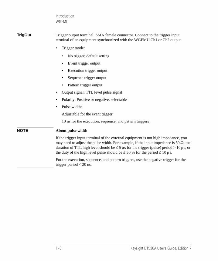
TrigOut Trigger output terminal. SMA female connector. Connect to the trigger input terminal of an equipment synchronized with the WGFMU Ch1 or Ch2 output.
• Trigger mode:
• No trigger, default setting
• Event trigger output
• Execution trigger output
• Sequence trigger output
• Pattern trigger output
• Output signal: TTL level pulse signal
• Polarity: Positive or negative, selectable
• Pulse width:
Adjustable for the event trigger
10 ns for the execution, sequence, and pattern triggers
NOTE About pulse width
If the trigger input terminal of the external equipment is not high impedance, you may need to adjust the pulse width. For example, if the input impedance is 50 , the duration of TTL high level should be 5 s for the trigger (pulse) period > 10 s, or the duty of the high level pulse should be 50 % for the period 10 s.
For the execution, sequence, and pattern triggers, use the negative trigger for the trigger period < 20 ns.
1-6 Keysight B1530A User’s Guide, Edition 7

IntroductionRSU
RSUKeysight B1531A RSU is supplied for each channel of each WGFMU module. The RSU is designed to be mounted on the wafer prober close to the device under test (DUT) to optimize measurement performance. In addition to its primary measurement functions, the RSU has a triaxial connector that can be used with a source/monitor unit (SMU). This permits switching between the WGFMU and SMU without having to change any cabling.
Normally, the RSU makes the path from the SMU input terminal to the RSU output terminal. When the WGFMU channel performs the voltage output or the IV measurement, the RSU makes the path from the WGFMU input terminal to the RSU output terminal.
Figure 1-3 B1531A Remote-sense and Switch Unit (RSU)
NOTE To avoid unintentional results
Timing between channels can be affected by electrostatic discharge. To avoid unintentional results, keep hands off of terminals while measurement is being performed.
From B1530A
V Monitor (BNC-female)Output (SMA-female)
From SMU (Triax-female)
x 1450 Ω
Keysight B1530A User’s Guide, Edition 7 1-7

IntroductionRSU
Output RSU output terminal to be connected to the DUT interface. SMA female connector. Connect to a DC probe or a RF probe.
Maximum output voltage is ±10 V when the WGFMU output appears and ±25 V when the SMU output appears.
From SMU SMU connection terminal. Triaxial BNC female connector. Connect to the Force terminal of a SMU installed in the B1500A with the WGFMU if you want to use the SMU.
NOTE To connect SMU
To connect a cable between the From SMU terminal and a SMU, disconnect DUT from Output. Otherwise changing the cable connection may damage the DUT.
CAUTION To apply SMU output
Maximum input voltage to the From SMU terminal is ±25 V. Do not apply voltage which exceeds this limit. Or the RSU will be damaged.
V Monitor Voltage monitor terminal. BNC female connector. Connect an oscilloscope if you want to monitor the output waveform.
If the RSU makes the path to the From SMU terminal, the V Monitor terminal will be internally connected to ground.
If the RSU makes the path to the From Keysight B1530A terminal, the V Monitor terminal will be internally connected to the 450 output impedance and the 1 amplifier. So if an oscilloscope channel with high impedance is connected to the V Monitor terminal, the oscilloscope will measure and show 5 V (=51) when the WGFMU outputs 5 V.
If an oscilloscope channel with 50 input impedance is connected to the V Monitor terminal, the oscilloscope will measure and show 0.5 V (=50.1) when the WGFMU outputs 5 V.
From Keysight B1530A
WGFMU connection terminal. Connect to the WGFMU Ch 1 or Ch 2 terminal.
CAUTION The B1500A must be turned off before connecting/disconnecting the cable between the RSU and the WGFMU Ch 1/Ch 2 terminal.
1-8 Keysight B1530A User’s Guide, Edition 7

IntroductionAccessories and Options
Accessories and OptionsKeysight B1530A is furnished with the following accessories.
• Keysight B1531A Remote Sense and Switch Unit, RSU, 2 ea.
• Sync terminal connection cable, 1 ea.
• Instrument Library and Sample Program CD, 1 ea.
• User’s Guide, 1 ea.
Keysight B1530A User’s Guide, Edition 7 1-9
IntroductionAccessories and Options
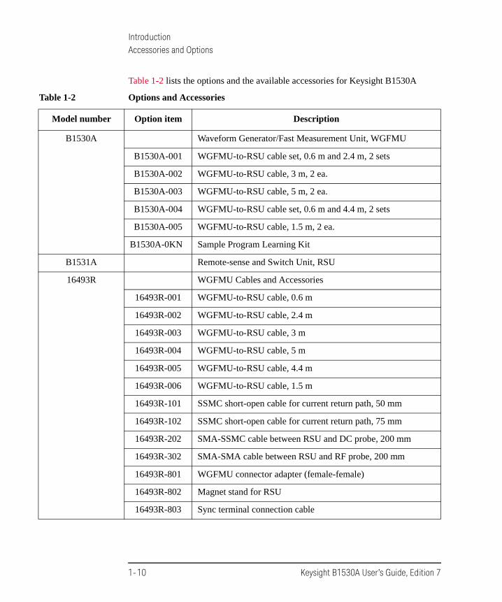
Table 1-2 lists the options and the available accessories for Keysight B1530A
Table 1-2 Options and Accessories
Model number Option item Description
B1530A Waveform Generator/Fast Measurement Unit, WGFMU
B1530A-001 WGFMU-to-RSU cable set, 0.6 m and 2.4 m, 2 sets
B1530A-002 WGFMU-to-RSU cable, 3 m, 2 ea.
B1530A-003 WGFMU-to-RSU cable, 5 m, 2 ea.
B1530A-004 WGFMU-to-RSU cable set, 0.6 m and 4.4 m, 2 sets
B1530A-005 WGFMU-to-RSU cable, 1.5 m, 2 ea.
B1530A-0KN Sample Program Learning Kit
B1531A Remote-sense and Switch Unit, RSU
16493R WGFMU Cables and Accessories
16493R-001 WGFMU-to-RSU cable, 0.6 m
16493R-002 WGFMU-to-RSU cable, 2.4 m
16493R-003 WGFMU-to-RSU cable, 3 m
16493R-004 WGFMU-to-RSU cable, 5 m
16493R-005 WGFMU-to-RSU cable, 4.4 m
16493R-006 WGFMU-to-RSU cable, 1.5 m
16493R-101 SSMC short-open cable for current return path, 50 mm
16493R-102 SSMC short-open cable for current return path, 75 mm
16493R-202 SMA-SSMC cable between RSU and DC probe, 200 mm
16493R-302 SMA-SMA cable between RSU and RF probe, 200 mm
16493R-801 WGFMU connector adapter (female-female)
16493R-802 Magnet stand for RSU
16493R-803 Sync terminal connection cable
1-10 Keysight B1530A User’s Guide, Edition 7

2 Installation

Installation
This chapter covers the following topics. The RF probes and the DC probes will be required to make contact with the device under test (DUT). To perform the measurement, complete the instructions described in this chapter.
• “RF Probes”
• “DC Probes”
• “To Connect Measurement Cables”
• “To Perform Self-Test”
• “To Install Instrument Library”
See Keysight B1500 manual for inspection of the delivered goods and installation of the B1500A.
NOTE About WGFMU module installation
Module installation of WGFMU must be performed by Keysight Technologies service personnel. Contact Keysight Technologies for the module installation.
CAUTION Using torque wrench and open-end wrench
For the RF measurements, it is important to carefully contact and fasten the connectors of the RF cables. The condition of the cable connections may change the measurement result characteristics. Therefore treat the RF cables carefully, especially the RF connectors, and use the torque wrench and the open-end wrench when you fasten the RF connectors. The recommended tools are listed in Table 2-1.
CAUTION Using cable tie
Use a cable tie to secure the cables. Then, do not tug the cable tie. You must treat the RF cables carefully to avoid the damage.
Table 2-1 Recommended Tools
Keysight part number Description
8710-1582 Torque wrench, 5 lb.
8710-1765 Torque wrench, 8 lb.
5185-2174 Open-end wrench, 5/16 inch
5188-4367 Open-end wrench, 11/32 inch
2-2 Keysight B1530A User’s Guide, Edition 7

InstallationRF Probes
RF ProbesThe RF measurement system supports the measurement of the three-terminal MOSFET (source and well (substrate) are shorted) by using the RF probes as shown in Figure 2-1. One measurement path is for the gate terminal and the other path is for the drain terminal. Moreover the source/well terminal must be electrically connected to the ground via the shielding of the measurement path (RF probes and measurement cables). See Figure 2-2.
Figure 2-1 RF Probes
Prepare two RF probes to perform the RF measurement. The RF probe must have the signal line and the ground lines as shown in Figure 2-2. The signal line is to contact the gate or drain pad, and the ground lines are to contact the source/well pads. For the RF probe and its installation, consult your favorite prober vender. Figure 2-1 shows the RF probes of Cascade Microtech, Inc.
Figure 2-2 Contact Pad and Probe Tip
to Drainto Gate
Signal
Gnd
Gnd
Signal
Gnd
GndGate Drain
RF probeRF probe Source/Well
Source/Well
Keysight B1530A User’s Guide, Edition 7 2-3

InstallationDC Probes
DC ProbesThe MOSFET contact pads for DC measurement shown in Figure 2-3, are more popular than the RF contact pads shown in Figure 2-2. If device under test is configured with DC contact pads, use DC probes instead of RF probes. The DC probes are better suited for contact with the DC contact pads than the RF probes. See Figure 2-3 for the contact pads and the DC probes.
Prepare four DC probes and three connection cables to connect the DC probes together. The model number of connection cable is 16493R-101 or 16493R-102.
• 16493R-101: 50 mm length SSMC short-open cable
• 16493R-102: 75 mm length SSMC short-open cable
For more information, see “Connecting DC Probes” on page 2-12.
Figure 2-3 Contact Pad and DC Probe Connection
Well
Gate
Source
Drain
16493R-101/102 This makes current return path.
16493R-101/102This shorts Well and Source.
Signal Signal
GndGnd
Gate DC probe
Source DC probe
Drain DC probe
Well DC probe
2-4 Keysight B1530A User’s Guide, Edition 7
InstallationTo Connect Measurement Cables
To Connect Measurement CablesThis section covers the instructions to make connection between WGFMU and RF/DC probes. Before starting the instructions, complete the installation of the B1500A installed with the WGFMU. See Keysight B1500 manual.
While performing the following instructions, turn the B1500A off and disconnect the power cable.
• “Connecting RSU”
• “Connecting RF Probes”
• “Connecting DC Probes”
CAUTION The B1500A must be turned off before connecting/disconnecting the cable between the RSU and the WGFMU Ch 1/Ch 2 terminal.
NOTE For unused channels
Measurement terminals can be opened. Cable connection is not required. With the open condition, the channels will pass the self-test and skip the self-calibration. But controlling the channel will cause a run-time error.
NOTE Cables used for the same measurement
Connect all measurement cables to the appropriate terminals, tie them up together, and make them stable by taping or something. This is important to reduce an environmental noise.
Keysight B1530A User’s Guide, Edition 7 2-5

InstallationTo Connect Measurement Cables
Connecting RSU
Prepare the required accessories and connect cables between RSU and WGFMU or SMU. See Table 2-2 for a connection example. This example connects three RSUs.
Required accessories:
• WGFMU-to-RSU cable (D-sub), 1 ea. per one RSU
1.5 m, 3 m, or 5 m cable (16493R-006, 003, or 004)
The 16493R-801 adapter is required and mounted on a shielding box to make connection to the RSU in the shielding box. Then the 60 cm and 2.4 m cables (16493R-001 and 002) or the 60 cm and 4.4 m cables (16493R-001 and 005) are required instead of the 1.5 m, 3 m, or 5 m cable.
• Sync connection cable (furnished with B1530A), 1 ea. between two WGFMUs
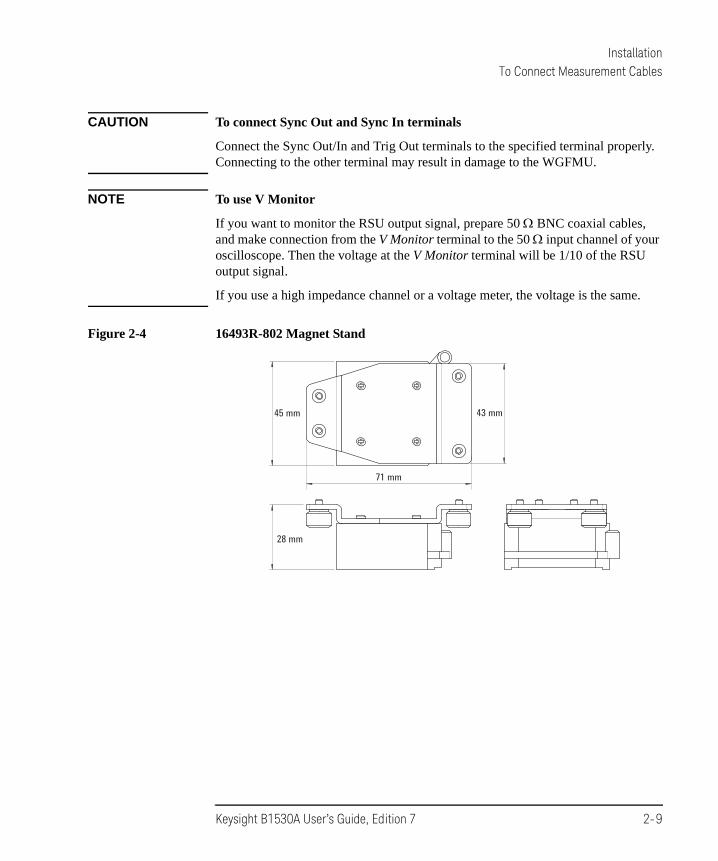
• Magnet stand (16493R-802), 1 ea. per one RSU, optional. The magnet stand is useful for fixing RSU. See Figure 2-4 for dimensions.
• Triaxial cable (SMU to RSU), 1 ea. per one RSU, optional
1.5 m or 3 m cable (16494A-001 or 002)
The 16495H-001 or 16495J-001 connector plate is required and mounted on a shielding box to make connection to the RSU in the shielding box. Then the 80 cm or 40 cm cable (16494A-003 or 004) is additionally required.
• 16495K-001 plate with cable holder
Instead of using both 16493R-801 and 16495H/J-001.
NOTE Keysight 16493R-801 adapter, 16495H/J-001 plate, and 16495K-001 plate
The 16493R-801 is used to connect the cable from WGFMU and the cable from RSU. Make an opening and screw holes on the shielding box. See Figure 2-5 for the dimensions of adapter and for the opening and screw holes which are required to mount the adapter on the shielding box.
The 16495H/J-001 is used to connect the cable from SMU and the cable from RSU.
Instead of using both 16493R-801 and 16495H/J-001, the 16495K can be used to pass the cables into the shielding box.
See Keysight 16495 Installation Guide for the dimensions of plate and for the opening and screw holes which are required to mount the plate on the shielding box.
2-6 Keysight B1530A User’s Guide, Edition 7

InstallationTo Connect Measurement Cables
Table 2-2 RSU Connection Example
From Cable To Slot number
SMU (RSU3) 1.5 m or 3 m triaxial cable (16494A-001 or 002) Force 5 (SMU)
SMU (RSU2) Force 4 (SMU)
SMU (RSU1) Force 3 (SMU)
WGFMU (RSU3) 1.5 m, 3 m, or 5 m WGFMU-to-RSU cable (16493R-006, 003, or 004)
Ch 1 2 (WGFMU)
WGFMU (RSU2) Ch 2 1 (WGFMU)
WGFMU (RSU1) Ch 1 1 (WGFMU)
Sync Out a
a. Sync Out connector of WGFMU installed in the slot 1.
Sync connection cable, furnished with B1530A Sync In b
b. Sync In connector of WGFMU installed in the slot 2.
1 and 2
to 301
to 201
to 401
to 501
101
201
301
401
102
202
to probe
to probe
Keysight B1500A
101, 102, 201, 202, 301, 401, and 501 indicate the channel number.
RSU 2
RSU 3
to 102
to 101
to probe
RSU 1
501
Keysight B1530A User’s Guide, Edition 7 2-7

InstallationTo Connect Measurement Cables
Procedure:
1. Mount 16343R-801 adapter, 16495H/J-001 plate, or 16495K-001 plate on the shielding box. Then consult your prober vender or the vender of shielding box.
2. Set RSU to the appropriate place. RSU must be fixed to the best position for accessing its connectors.
Dimensions of RSU are 45.2 mm (W) 70.0 mm (H) 82.0 mm (D) excluding the connectors.
If you use 16493R-802 magnet stand, see Figure 2-4 for dimensions.
3. If adapter or plate is used, connect the required cables to the following connectors.
In the shielding box:
• D-sub connector on the adapter, for 60 cm cable
• Triaxial connector on the plate, for 80 cm or 40 cm cable, optional for SMU
Out of the shielding box:
• D-sub connector on the adapter, for 2.4 m or 4.4 m cable
• Triaxial connector on the plate, for 1.5 m or 3 m cable, optional for SMU
4. If the 16495K is used, pass the required cables through the cable hole of the 16495K, adjust the cable length in the shielding box, and cover the cable holder of the 16495K.
5. Connect the WGFMU-to-RSU cable to the From Keysight B1530A terminal of RSU.
6. Optional for SMU. Connect the triaxial cable to the From SMU terminal of RSU.
7. Connect the WGFMU-to-RSU cable to the Ch 1 or Ch2 terminal of WGFMU.
8. Optional for SMU. Connect the triaxial cable to the Force terminal of SMU.
9. If multiple WGFMUs are installed and used, connect the Sync connection cable between the Sync Out terminal of the master WGFMU and the Sync In terminal of the slave WGFMU. See Table 2-2 for a connection example.
NOTE Master WGFMU and slave WGFMU
The master WGFMU means the module installed in the lower slot. And the slave WGFMU means the module following to the master WGFMU.
2-8 Keysight B1530A User’s Guide, Edition 7
InstallationTo Connect Measurement Cables
CAUTION To connect Sync Out and Sync In terminals
Connect the Sync Out/In and Trig Out terminals to the specified terminal properly. Connecting to the other terminal may result in damage to the WGFMU.
NOTE To use V Monitor
If you want to monitor the RSU output signal, prepare 50 BNC coaxial cables, and make connection from the V Monitor terminal to the 50 input channel of your oscilloscope. Then the voltage at the V Monitor terminal will be 1/10 of the RSU output signal.
If you use a high impedance channel or a voltage meter, the voltage is the same.
Figure 2-4 16493R-802 Magnet Stand
45 mm 43 mm
71 mm
28 mm
Keysight B1530A User’s Guide, Edition 7 2-9

InstallationTo Connect Measurement Cables
Figure 2-5 16493R-801 Adapter
10.3
mm
37.5
mm
34.8
mm
38 m
m31
.7 m
m9.7
mm
17.5
mm
57.5
mm
75 m
m
37.5
mm
20.7
mm
4-M
3 in
sert
nut
55 m
m
40 m
m
15 m
m22
mm
4-
3.4φ
Open
ing
for c
onne
ctor
Scre
w h
ole:
To m
ount
Key
sight
164
93R-
801
onth
e sh
ieldin
g bo
x, an
ope
ning
for
conn
ecto
r and
four
scre
w h
oles
are
requ
ired
on th
e sh
ieldin
g bo
x.
2-10 Keysight B1530A User’s Guide, Edition 7

InstallationTo Connect Measurement Cables
Connecting RF Probes
Only for the RF probe users. Connect the following cables as shown in Figure 2-6. Use a torque wrench and an open-end wrench to fasten the SMA connectors.
Required accessories:
• RF prober, 2 ea.
• 16493R-302 20 cm length SMA-SMA cable, 2 ea.
Procedure:
1. Connect a SMA-SMA cable between a RSU (ex: RSU1) and the Drain RF probe. And set the Drain RF probe to the appropriate place.
2. Connect the other SMA-SMA cable between the other RSU (ex: RSU2) and the Gate RF probe. And set the Gate RF probe to the appropriate place.
Figure 2-6 RF Probe Connections
to Drain to Gate
from RSU
16493R-302
1
from RSU
2
Keysight B1530A User’s Guide, Edition 7 2-11

InstallationTo Connect Measurement Cables
Connecting DC Probes
Only for the DC probe users. Connect the following cables as shown in Figure 2-7. Use a torque wrench and an open-end wrench to fasten the SMA connectors.
Required accessories:
• DC prober, 4 ea.
• 16493R-202 20 cm length SMA-SSMC cable, 2 ea.
• 16493R-101: 50 mm length SSMC short-open cable or
16493R-102: 75 mm length SSMC short-open cable, total 3 ea.
For the external view and the internal connection, see Figure 2-8.
Figure 2-7 DC Probe Connections
Well
Gate
Source
Drain
1 2
3
45
Signal Signal
GndGnd
from RSU16493R-202from RSU
16493R-202
16493R-101/102
16493R-101/102
Gate DC probe
Well DC probeSource DC probe
Drain DC probe
2-12 Keysight B1530A User’s Guide, Edition 7

InstallationTo Connect Measurement Cables
Procedure:
1. Connect a SSMC short-open cable between the Gate DC probe and the Well DC probe, and set the DC probes to the appropriate place. Then, the black sleeve plug must be the Gate side. This electrically connects the Well probe needle, Well probe shield, and Gate probe shield together.
2. Connect a SSMC short-open cable between the Drain DC probe and the Source DC probe, and set the DC probes to the appropriate place. Then, the black sleeve plug must be the Drain side. This electrically connects the Source probe needle, Source probe shield, and Drain probe shield together.
3. Connect the last SSMC short-open cable between the Well DC probe and the Source DC probe, and set the DC probes to the appropriate place. Then, the black sleeve plug must be the Source side. This electrically connects the Well probe needle, Well probe shield, and Source probe shield together.
4. Connect a SMA-SSMC cable between a RSU (ex: RSU1) and the Drain DC probe. And set the Drain DC probe to the appropriate place.
5. Connect the other SMA-SSMC cable between the other RSU (ex: RSU2) and the Gate DC probe. And set the Gate DC probe to the appropriate place.
Figure 2-8 SSMC Short-Open Cable
50 mm or 75 mm
Black
SSMC(plug)SSMC(plug)
Yellow
Signal line and shield are shorted. no signal pin
Keysight B1530A User’s Guide, Edition 7 2-13

InstallationTo Perform Self-Test
To Perform Self-TestAfter completing the measurement cable connections, check the operation of the Keysight B1500A as shown below.
1. Open the measurement terminals at the DUT interface.
2. Connect the power cable to the B1500A. And connect it to an AC power outlet.
3. Turn the B1500A on. The power-on self-test will run automatically. And wait until the Start EasyEXPERT window appears. The WGFMU and the RSU are recognized by the EasyEXPERT software revision A.03.20 or later.
4. Click the Start EasyEXPERT button. And wait until the EasyEXPERT main screen or workspace selection screen is displayed.
5. If the workspace selection screen is displayed, follow the instruction on the screen and open the EasyEXPERT main screen.
6. On the EasyEXPERT main screen, click the Configuration button. The Configuration window appears.
7. On the Configuration window, click the Module tab. The window shows the slot configuration and the self-test results. The Status of all modules must be PASS.
For more details, see EasyEXPERT manual.
If the B1500A or any module fails the self-test, contact Keysight Technologies.
2-14 Keysight B1530A User’s Guide, Edition 7

InstallationTo Install Instrument Library
To Install Instrument LibraryThis section describes the instructions to install the Keysight B1530A WGFMU Instrument Library to an instrument controller (Windows PC).
• “System Requirements”
• “Installing Instrument Library”
• “Before Programming”
System Requirements
The following system environments are required for the instrument controller. The system requirements are effective as of June 2011. For the latest information, go to www.keysight.com and type in B1530A in the Search field at the top of the page.
• Computer and peripherals
Required specifications depend on the application development environment (programming software shown below). See manual of the programming software you use.
• Operating system
Microsoft Windows XP Professional SP3 or later, Windows Vista Business SP2 or later (32bit only), and Windows 7 Professional SP1 or later (32 bit and 64bit)
• GPIB (IEEE 488) interface and software
Keysight 82350B GPIB interface and Keysight IO Library Suite 15.0 or later
• Programming software
Microsoft Visual Studio 2005 Express edition or later, Visual C++ .NET, Visual C# .NET, Visual Basic .NET, Visual Basic 6.0, VBA, or TransEra HTBasic for Windows (release 8.3 or later)
Keysight B1530A User’s Guide, Edition 7 2-15

InstallationTo Install Instrument Library
Installing Instrument Library
The installation flow is shown below. If you have already installed the GPIB interface, Keysight IO Library Suite, and programming software on your computer, skip steps 1 through 4.
1. Install the GPIB interface to a computer to be an instrument controller.
See manual of the GPIB interface. Note the model number of the GPIB interface, as you may need it to configure the interface (in step 3).
2. Install the Keysight IO Library Suite.
Follow the setup program instructions.
3. Configure and check the GPIB interface.
See manual of the Keysight IO Library Suite.
4. Install the programming software.
Follow the setup program instructions.
5. Install the Keysight B1530A WGFMU Instrument Library.
a. Insert the Keysight B1530A Instrument Library and Sample Program CD to the CD-ROM drive.
b. Execute setup.exe of the Instrument Library and follow the instructions of the setup wizard.
c. Wait for installation to complete, and remove the CD from the CD-ROM drive.
2-16 Keysight B1530A User’s Guide, Edition 7

InstallationTo Install Instrument Library
Before Programming
Before starting the programming using an instrument controller, perform following.
1. Terminate the Keysight EasyEXPERT software on the B1500A as follows.
a. Select File > Exit on the EasyEXPERT main window.
b. Click [x] at the upper right corner of the Start EasyEXPERT button.
2. Open the Keysight Connection Expert window on the B1500A by clicking Keysight IO Control icon on the Windows task bar and selecting Keysight Connection Expert.
3. Change the following setup items as shown below. The setup window can be opened by highlighting GPIB0 in the Instrument I/O on this PC area, and clicking Change Properties... button.
GPIB address B1500A’s GPIB address (ex: 17)
System Controller No
Auto-discover No
The factory shipment initial values are 17, No, and No, respectively.
4. Reboot the B1500A if the System Controller setting is changed from Yes to No.
NOTE Start EasyEXPERT button
After rebooting the B1500A, leave the Start EasyEXPERT button on the B1500A’s screen. The button must be displayed on the screen or minimized to the Windows task bar. The Start EasyEXPERT service must be run to control the B1500A from an external computer.
NOTE B1500A in remote mode
Once the B1500A receives a GPIB command, the Start EasyEXPERT button is minimized to the Windows task bar, and the FlexGUI window is opened. This window is the status indicator of the B1500A in the GPIB remote state and provides some graphical user interface. For details, see Keysight B1500 Series Programming Guide.
Keysight B1530A User’s Guide, Edition 7 2-17

InstallationTo Install Instrument Library
2-18 Keysight B1530A User’s Guide, Edition 7

3 Using Instrument Library

Using Instrument Library
This chapter introduces programming summary and example programs by using the Keysight B1530A WGFMU Instrument Library and consists of the following sections. For the details of the functions, see Chapter 4, “Instrument Library Reference.”
• “Programming Overview”
• “Programming Examples”
• “If You Perform DC Measurement”
CAUTION Before turning the B1500A on
Connect the cable between the RSU and the WGFMU Ch 1/Ch 2 terminal. This prevents the RSU from damage.
NOTE After turning the B1500A on
Use EasyEXPERT to confirm that the B1500A, the WGFMU, and the RSU pass the self-test. If anything fails the self-test, perform the self-test again. If it fails again, contact your nearest Keysight Technologies.
NOTE Before starting measurement
Perform the self-calibration of the WGFMU and the RSU. This minimizes the measurement error.
3-2 Keysight B1530A User’s Guide, Edition 7

Using Instrument LibraryProgramming Overview
Programming OverviewWGFMU control program can be created by using the functions listed in Table 3-1. Execute the functions in this order.
The WGFMU online session is started by the WGFMU_openSession function and is ended by the WGFMU_closeSession function. This means that the functions for the step 1 to 3 can be used in the offline condition which the WGFMU is not connected.
The WGFMU channel output and measurement control data can be created by the step 1 to 3. And you can check the data by using the WGFMU_exportAscii function before opening the session. This function creates a csv (comma separated value) data file which can be opened by a spreadsheet software. You can verify the timing, waveform pattern, and sequence by using a graph on the spreadsheet software.
Table 3-1 Summary of Execution Flow
Step Action Function
Optional. Starts error and warning logging WGFMU_openLogFile
Optional. Clears instrument library WGFMU_clear
1 Creates pattern data See Table 3-2.
2 Defines several events See Table 3-3.
3 Creates WGFMU channel output and measurement control data
WGFMU_addSequence
WGFMU_addSequences
4 Opens session WGFMU_openSession
Optional. Initializes WGFMU channels WGFMU_initialize
5 Sets measurement condition See Table 3-4.
6 Enables WGFMU channels WGFMU_connect
7 Starts output and measurement WGFMU_execute
8 Disables WGFMU channels WGFMU_disconnect
9 Closes session WGFMU_closeSession
Optional. Stops error and warning logging WGFMU_closeLogFile
Keysight B1530A User’s Guide, Edition 7 3-3

Using Instrument LibraryProgramming Overview
Table 3-2 To Create Pattern Data
Table 3-3 To Define Measurement Events, Range Events, and Trigger Events
Function Description
WGFMU_createPattern Creates waveform pattern
WGFMU_addVector
WGFMU_addVectors
WGFMU_setVector
WGFMU_setVectors
WGFMU_createMergedPattern Creates pattern by merging patterns
WGFMU_createMultipliedPattern Creates pattern by multiplying pattern
WGFMU_createOffsetPattern Creates pattern by adding offset to pattern
Function Description
WGFMU_setMeasureEvent Defines a measurement event which is a sampling measurement performed by the WGFMU channel while it outputs a waveform pattern.
WGFMU_setRangeEvent Defines a range event which is the range change operation for the current measurement performed by the WGFMU channel while it outputs a waveform pattern.
WGFMU_setTriggerOutEvent Defines a trigger output event which is the trigger output operation performed by the WGFMU channel while it outputs a waveform pattern.
3-4 Keysight B1530A User’s Guide, Edition 7

Using Instrument LibraryProgramming Overview
Table 3-4 To Set Measurement Condition
Table 3-5 lists a part of useful functions. For all functions, see Chapter 4, “Instrument Library Reference.”
Table 3-5 Other Useful Functions
Step Action Function
1 Sets operation mode WGFMU_setOperationMode
2 Sets voltage output range WGFMU_setForceVoltageRange
3 Enables measurement ability WGFMU_setMeasureEnabled
4 Sets measurement mode WGFMU_setMeasureMode
5 Sets measurement range WGFMU_setMeasureCurrentRange
WGFMU_setMeasureVoltageRange
6 Reads the measurement data (time and voltage or current) for the measurement point defined in the sequences set to the specified WGFMU channel.
WGFMU_getMeasureValueSize
WGFMU_getMeasureValues
WGFMU_getMeasueValue
Function Description
WGFMU_update Applies WGFMU setup
WGFMU_updateChannel
WGFMU_abort Stops WGFMU operation
WGFMU_abortChannel
WGFMU_getChannelIdSize Reads channel id of WGFMU channels installed in the B1500A
WGFMU_getChannelIds
WGFMU_doSelfCalibration Performs self-calibration
WGFMU_doSelfTest Performs self-test
WGFMU_exportAscii Creates a setup summary report and saves it to a csv (comma separated values) file
Keysight B1530A User’s Guide, Edition 7 3-5

Using Instrument LibraryProgramming Examples
Programming ExamplesThis section describes simple programming examples using the WGFMU Instrument Library and Microsoft Visual C++ programming software. This section covers the following topics and the examples shown in Table 3-6.
• “To Create Your Project Template”
• “To Create Measurement Program”
Table 3-6 Summary of Programming Examples
Section title Description
Example 1 This example creates a waveform data and applies the waveform voltage.
Example 2 Sampling measurement code and data storage code are added to Example 1.
Example 3 Error handling is added to Example 2 and the data storage code is deleted.
Example 4 Error handling is added to Example 2 and the data storage code is deleted.
Example 5 Error handling is added to Example 2 and the data storage code is deleted.
Example 6 This example is similar to Example 2 but uses two WGFMU channels.
Example 7 Data retrieving is changed from Example 6.
Example 8 Data retrieving is changed from Example 6.
Example 9 This example performs Id-Vg measurement and saves measurement result data.
Example 10 Source output control code for SMU is added to the code similar to Example 3.
Example 11 Sampling measurement code for SMU is added to the code similar to Example 3.
3-6 Keysight B1530A User’s Guide, Edition 7

Using Instrument LibraryProgramming Examples
To Create Your Project Template
This section describes how to create a project template using Microsoft Visual C++ programming software. Before starting programming, create your project template, and keep it as your reference. It will remove the conventional task in the future programming.
Step 1. Connect the B1500A to your instrument controller via GPIB.
Step 2. Launch the programming software and create a new project. Then, select the Win32 project or the console application for the new project template selection. They will simplify the programming. Of course, other project template can be used.
Step 3. Define the following to the project properties or the project options. See manual or on-line help of the programming software for defining them.
1. Additional include file search path:
<user path>\Agilent\B1530A\include which stores the wgfmu.h file
<user path>\VISA\winnt\include which stores the VISA related include files, optional
2. Additional library search path:
<user path>\Agilent\B1530A\lib which stores the wgfmu.lib file
<user path>\VISA\winnt\lib\msc which stores the VISA related library files for Microsoft Visual C++, optional
3. Additional project link library:
wgfmu.lib
visa32.lib, optional. Needed to execute Example 10 or 11.
<user path> indicates the folder the software is installed.
Step 4. Open a source file (.cpp) in the project, and enter a program code as template. See Table 3-7 for example.
Step 5. Save the project as your template (e.g. \test\my_temp).
Keysight B1530A User’s Guide, Edition 7 3-7

Using Instrument LibraryProgramming Examples
Table 3-7 Example Program Code for Project Template
#include "stdafx.h"#include <stdio.h>#include <stdlib.h>#include <visa.h> //optional#include "wgfmu.h"
void checkError(int ret) // 7{
if(ret < WGFMU_NO_ERROR) {throw ret;
}}
int checkError2(int ret) //14{
if( ret < WGFMU_NO_ERROR ) { int size; WGFMU_getErrorSize(&size); char* msg = new char[size + 1]; WGFMU_getError(msg, &size); fprintf(stderr, "%s", msg ); delete [] msg;
}return ret;
}
Line Description
1 to 5 Required to use the WGFMU instrument library. The header files contain various necessary information such as function declaration and macro definitions.
You may add the include statements to call another header files which may be needed by the codes you added. Also, the include statements may be written in a header file which will be called by the source file (e.g. #include <stdio.h> may be written in the stdafx.h header file which will be called by the source file).
7 to 12 Checks if the passed “ret” value indicates normal status, and returns to the line in the try statement in the measurement program code. If the value indicates an error status, go to the catch statement.
14 to 25 Checks if the passed “ret” value indicates normal status, and returns to the line in the measurement program code. If the value indicates an error status, the error message will be displayed.
3-8 Keysight B1530A User’s Guide, Edition 7
Using Instrument LibraryProgramming Examples
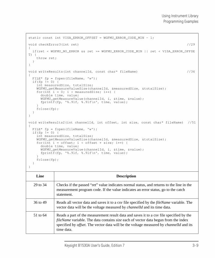
static const int VISA_ERROR_OFFSET = WGFMU_ERROR_CODE_MIN - 1;
void checkError3(int ret) //29{
if(ret < WGFMU_NO_ERROR && ret >= WGFMU_ERROR_CODE_MIN || ret < VISA_ERROR_OFFSET) {
throw ret;}
}
void writeResults(int channelId, const char* fileName) //36{
FILE* fp = fopen(fileName, "w");if(fp != 0) {
int measuredSize, totalSize;WGFMU_getMeasureValueSize(channelId, &measuredSize, &totalSize);for(int i = 0; i < measuredSize; i++) {
double time, value;WGFMU_getMeasureValue(channelId, i, &time, &value);fprintf(fp, "%.9lf, %.9lf\n", time, value);
}fclose(fp);
}}
void writeResults2(int channelId, int offset, int size, const char* fileName) //51{
FILE* fp = fopen(fileName, "w");if(fp != 0) {
int measuredSize, totalSize;WGFMU_getMeasureValueSize(channelId, &measuredSize, &totalSize);for(int i = offset; i < offset + size; i++) {
double time, value;WGFMU_getMeasureValue(channelId, i, &time, &value);fprintf(fp, "%.9lf, %.9lf\n", time, value);
}fclose(fp);
}}
Line Description
29 to 34 Checks if the passed “ret” value indicates normal status, and returns to the line in the measurement program code. If the value indicates an error status, go to the catch statement.
36 to 49 Reads all vector data and saves it to a csv file specified by the fileName variable. The vector data will be the voltage measured by channelId and its time data.
51 to 64 Reads a part of the measurement result data and saves it to a csv file specified by the fileName variable. The data contains size each of vector data begun from the index specified by offset. The vector data will be the voltage measured by channelId and its time data.
Keysight B1530A User’s Guide, Edition 7 3-9

Using Instrument LibraryProgramming Examples
void writeResults3(int channelId1, int channelId2, int offset, int size, const char* fileName) //66{
FILE* fp = fopen(fileName, "w");if(fp != 0) {
int measuredSize, totalSize;WGFMU_getMeasureValueSize(channelId2, &measuredSize, &totalSize);for(int i = offset; i < offset + size; i++) {
double time, value, voltage;WGFMU_getMeasureValue(channelId2, i, &time, &value);WGFMU_getInterpolatedForceValue(channelId1, time, &voltage);fprintf(fp, "%.9lf, %.9lf\n", voltage, value);
}fclose(fp);
}}
int main() //82{
// Insert your code here}
Line Description
66 to 80 Reads a part of the measurement result data and saves it to a csv file specified by the fileName variable. The data contains size each of vector data begun from the index specified by offset. The vector data will be the voltage applied by channelId1 and the voltage measured by channelId2.
84 Measurement program code must be inserted.
3-10 Keysight B1530A User’s Guide, Edition 7

Using Instrument LibraryProgramming Examples
To Create Measurement Program
Create the measurement program as shown below. The following procedure needs your project template. If the procedure does not fit your programming environment, arrange it to suit your environment.
Step 1. Plan the automatic measurements. Then decide the following items:
• Measurement devices
Discrete, packaged, on-wafer, and so on.
• Parameters/characteristics to be measured
hFE, Vth, sheet resistance, and so on.
• WGFMU source output waveform
Pulse voltage, arbitrary linear waveform voltage, or DC voltage.
• Measurement condition
Current measurement or voltage measurement, sampling interval, measurement timing, and so on.
Step 2. Make a copy of your project template (e.g. \test\my_temp to \device_001\my_temp).
Step 3. Rename the copy (e.g. \device_001\my_temp to \device_001\ex1).
Step 4. Launch the programming software.
Step 5. Open the project (e.g. \device_001\ex1).
Step 6. Open the source file that contains the template code as shown in Table 3-7, and complete the main program. Then use the WGFMU instrument library functions.
Step 7. Insert the code to display, store, or calculate data into the program, if necessary.
Step 8. Save the project (e.g. \device_001\ex1).
Keysight B1530A User’s Guide, Edition 7 3-11
Using Instrument LibraryProgramming Examples
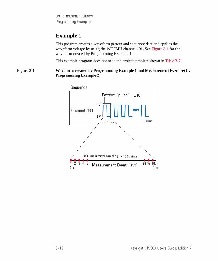
Example 1
This program creates a waveform pattern and sequence data and applies the waveform voltage by using the WGFMU channel 101. See Figure 3-1 for the waveform created by Programming Example 1.
This example program does not need the project template shown in Table 3-7.
Figure 3-1 Waveform created by Programming Example 1 and Measurement Event set by Programming Example 2
Pattern: “pulse”
Channel: 101
x10
0 V
1 V
Sequence
1 ms0 s 10 ms
0.01 ms interval sampling
100Measurement Event: “evt”1 5432 9998
x 100 points
1 ms0 s
3-12 Keysight B1530A User’s Guide, Edition 7

Using Instrument LibraryProgramming Examples
Table 3-8 Programming Example 1
#include "stdafx.h"#include <stdio.h>#include <stdlib.h>#include "wgfmu.h"
int main() // Pulse voltage output{
// OFFLINEWGFMU_clear(); // 9WGFMU_createPattern("pulse", 0); // 0 ms, 0 VWGFMU_addVector("pulse", 0.0001, 1); //0.1 ms, 1 VWGFMU_addVector("pulse", 0.0004, 1); //0.5 ms, 1 VWGFMU_addVector("pulse", 0.0001, 0); //0.6 ms, 0 VWGFMU_addVector("pulse", 0.0004, 0); //1.0 ms, 0 VWGFMU_addSequence(101, "pulse", 10); //10 pulse output //15
// ONLINEWGFMU_openSession("GPIB0::17::INSTR"); //18WGFMU_initialize();WGFMU_setOperationMode(101, WGFMU_OPERATION_MODE_FASTIV);WGFMU_connect(101);WGFMU_execute();WGFMU_waitUntilCompleted();WGFMU_initialize(); // WGFMU_disconnect(101); //24WGFMU_closeSession();
}
Line Description
9 Clears the B1530A instrument library.
10 to 14 Creates a waveform pattern data which is used to apply the voltage pulse.
15 Creates a sequence data.
18 to 19 Opens the session and initializes the all WGFMU channels.
20 to 23 Sets the fast IV mode for the WGFMU of the channel number 101, enables the channel, applies the WGFMU output, and waits until the output is completed.
24 to 25 Initializes the all WGFMU channels and closes the session.
Keysight B1530A User’s Guide, Edition 7 3-13

Using Instrument LibraryProgramming Examples
Example 2
This program is almost same as Example 1. Differences are the additional lines 10 and 20. This program performs sampling measurement with the WGFMU output same as Example 1 and saves measurement result data to the specified file. See Figure 3-1 for the waveform and the measurement event set by Programming Example 2.
This program uses a subprogram in the project template shown in Table 3-7.
Table 3-9 Programming Example 2
int main() // Pulse voltage output and sampling measurement // 1{
// OFFLINEWGFMU_clear();WGFMU_createPattern("pulse", 0); // 0 ms, 0 VWGFMU_addVector("pulse", 0.0001, 1); //0.1 ms, 1 VWGFMU_addVector("pulse", 0.0004, 1); //0.5 ms, 1 VWGFMU_addVector("pulse", 0.0001, 0); //0.6 ms, 0 VWGFMU_addVector("pulse", 0.0004, 0); //1.0 ms, 0 VWGFMU_setMeasureEvent("pulse", "evt", 0, 100, 0.00001, 0, WGFMU_MEASURE_EVENT_DA
TA_AVERAGED); // meas from 0 s, 100 points, 0.01 ms interval, no averaging //10WGFMU_addSequence(101, "pulse", 10); //10 pulse output
// ONLINEWGFMU_openSession("GPIB0::17::INSTR");WGFMU_initialize();WGFMU_setOperationMode(101, WGFMU_OPERATION_MODE_FASTIV);WGFMU_connect(101);WGFMU_execute(); //18WGFMU_waitUntilCompleted();writeResults(101, "C:/temp/B1530A/data/ex02.csv"); //20WGFMU_initialize(); // WGFMU_disconnect(101);WGFMU_closeSession();
}
Line Description
1 to 23 Almost same as Example 1.
10 Sets the sampling measurement timing parameters.
18 Applies the WGFMU output and performs the sampling measurement.
20 Calls the writeResults subprogram in the project template. Saves the measurement result data to the specified file.
3-14 Keysight B1530A User’s Guide, Edition 7

Using Instrument LibraryProgramming Examples
Example 3
This program performs measurement as same as Example 2. Then the execution result of each function is checked by using the checkError subprogram in the project template shown in Table 3-7. If an error is detected, this program displays the error message. The result data is not saved.
Table 3-10 Programming Example 3
int main() // Pulse voltage output and sampling measurement with error check // 1{
try {// OFFLINEcheckError(WGFMU_clear());checkError(WGFMU_createPattern("pulse", 0));checkError(WGFMU_addVector("pulse", 0.0001, 1));checkError(WGFMU_addVector("pulse", 0.0004, 1));checkError(WGFMU_addVector("pulse", 0.0001, 0));checkError(WGFMU_addVector("pulse", 0.0004, 0));checkError(WGFMU_setMeasureEvent("pulse", "evt", 0, 1000, 0.000001, 0, WGFMU_M
EASURE_EVENT_DATA_AVERAGED));checkError(WGFMU_setMeasureEvent("pulse", "evt", 0, 100, 0.00001, 0, WGFMU_MEA
SURE_EVENT_DATA_AVERAGED));checkError(WGFMU_addSequence(101, "pulse", 10)); //13
// ONLINEcheckError(WGFMU_openSession("GPIB0::17::INSTR"));checkError(WGFMU_initialize());checkError(WGFMU_setOperationMode(101, WGFMU_MEASURE_MODE_CURRENT)); //18checkError(WGFMU_connect(101));checkError(WGFMU_execute());checkError(WGFMU_waitUntilCompleted());checkError(WGFMU_initialize());checkError(WGFMU_closeSession());
}catch(int e) { // handle error //25
int size;WGFMU_getErrorSize(&size);char* error = new char[size + 1];WGFMU_getError(error, &size);fprintf(stderr, "%s", error);delete[] error;
} //32}
Line Description
5 to 23 Almost same as Example 2. Measurement result data is not saved.
11 to 12 Sets the sampling measurement timing parameters. Line 12 causes an overwrite warning.
18 Causes an error because of the invalid value WGFMU_MEASURE_MODE_CURRENT.
25 to 32 Reads and displays error message.
Keysight B1530A User’s Guide, Edition 7 3-15

Using Instrument LibraryProgramming Examples
Example 4
This program performs measurement as same as Example 2. Then the execution result of each function is checked by using the checkError2 subprogram in the project template shown in Table 3-7. If an error is detected, this program displays the error message. The result data is not saved.
Table 3-11 Programming Example 4
int main() // Pulse voltage output and sampling measurement with error check // 1{
// OFFLINEcheckError2(WGFMU_clear());checkError2(WGFMU_treatWarningsAsErrors(WGFMU_WARNING_LEVEL_SEVERE));checkError2(WGFMU_createPattern("pulse", 0));checkError2(WGFMU_addVector("pulse", 0.0001, 1));checkError2(WGFMU_addVector("pulse", 0.0004, 1));checkError2(WGFMU_addVector("pulse", 0.0001, 0));checkError2(WGFMU_addVector("pulse", 0.0004, 0));checkError2(WGFMU_setMeasureEvent("pulse", "evt", 0, 1000, 0.000001, 0, WGFMU_ME
ASURE_EVENT_DATA_AVERAGED));checkError2(WGFMU_setMeasureEvent("pulse", "evt", 0, 100, 0.00001, 0, WGFMU_MEAS
URE_EVENT_DATA_AVERAGED));checkError2(WGFMU_addSequence(101, "pulse", 10)); //13
// ONLINEcheckError2(WGFMU_openSession("GPIB0::17::INSTR"));checkError2(WGFMU_initialize());checkError2(WGFMU_setOperationMode(101, WGFMU_OPERATION_MODE_FASTIV));checkError2(WGFMU_connect(101));checkError2(WGFMU_execute());checkError2(WGFMU_waitUntilCompleted());checkError2(WGFMU_initialize());checkError2(WGFMU_closeSession()); //23
}
Line Description
1 to 24 Almost same as Example 2. Measurement result data is not saved.
5 Sets the threshold between warning and error. This sets the severe warning to error.
11 to 12 Sets the sampling measurement timing parameters. Line 12 causes an overwrite warning.
3-16 Keysight B1530A User’s Guide, Edition 7

Using Instrument LibraryProgramming Examples
Example 5
This program performs measurement as same as Example 2. After the measurement, this program reads and displays the error summary if it is not empty. The result data is not saved. This program does not use a subprogram in the project template shown in Table 3-7.
Table 3-12 Programming Example 5
int main() // Pulse voltage output and sampling measurement with error check // 1{
int ret; // just for monitoring execution result by using debugger// OFFLINEret = WGFMU_clear();ret = WGFMU_createPattern("pulse", 0);ret = WGFMU_addVector("pulse", 0.0001, 1);ret = WGFMU_addVector("pulse", 0.0004, 1);ret = WGFMU_addVector("pulse", 0.0001, 0);ret = WGFMU_addVector("pulse", 0.0004, 0);ret = WGFMU_setMeasureEvent("pulse", "evt", 0, 1000, 0.000001, 0, WGFMU_MEASURE_
EVENT_DATA_AVERAGED);ret = WGFMU_setMeasureEvent("pulse", "evt", 0, 100, 0.00001, 0, WGFMU_MEASURE_EV
ENT_DATA_AVERAGED);ret = WGFMU_addSequence(101, "pulse", 10); //13
// ONLINEret = WGFMU_openSession("GPIB0::17::INSTR");ret = WGFMU_initialize();ret = WGFMU_setOperationMode(101, WGFMU_MEASURE_MODE_CURRENT); //18ret = WGFMU_connect(101);ret = WGFMU_execute();ret = WGFMU_waitUntilCompleted();ret = WGFMU_initialize();ret = WGFMU_closeSession();
int size; //25WGFMU_getErrorSummarySize(&size);if(size > 0) {
char* errorSummary = new char[size + 1];WGFMU_getErrorSummary(errorSummary, &size);fprintf(stderr, "%s", errorSummary);delete[] errorSummary;
} //32}
Line Description
5 to 23 Almost same as Example 2. Measurement result data is not saved.
11 to 12 Sets the sampling measurement timing parameters. Line 12 causes an overwrite warning.
18 Causes an error because of the invalid value WGFMU_MEASURE_MODE_CURRENT.
25 to 32 Reads and displays error summary if it is not empty.
Keysight B1530A User’s Guide, Edition 7 3-17
Using Instrument LibraryProgramming Examples
Example 6
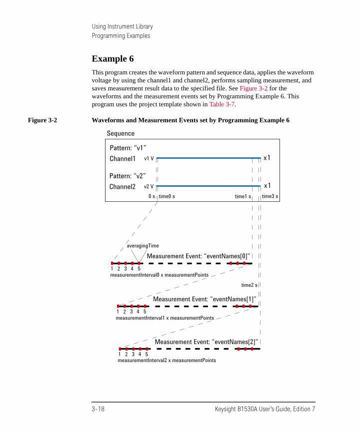
This program creates the waveform pattern and sequence data, applies the waveform voltage by using the channel1 and channel2, performs sampling measurement, and saves measurement result data to the specified file. See Figure 3-2 for the waveforms and the measurement events set by Programming Example 6. This program uses the project template shown in Table 3-7.
Figure 3-2 Waveforms and Measurement Events set by Programming Example 6
Sequence
Pattern: “v1”Channel1 x1v1 V
Pattern: “v2”Channel2 x1v2 V
time3 s0 s
time2 s
time1 stime0 s
measurementInterval0 x measurementPoints
Measurement Event: “eventNames[0]”
1 432
averagingTime
measurementInterval2 x measurementPoints
Measurement Event: “eventNames[2]”
1 432
measurementInterval1 x measurementPoints
Measurement Event: “eventNames[1]”
1 432
5
5
5
3-18 Keysight B1530A User’s Guide, Edition 7

Using Instrument LibraryProgramming Examples
Table 3-13 Programming Example 6
int main() // 1{
int measurementPoints = 32768;double measurementInterval0 = 100e-6;double measurementInterval1 = 10e-6;double measurementInterval2 = 1e-6;double averagingTime = 10e-9;double time0 = 1e-6;double time1 = time0 + measurementInterval0 * measurementPoints + averagingTime;double time2 = time1 + measurementInterval1 * measurementPoints + averagingTime;double time3 = time2 + measurementInterval2 * measurementPoints + averagingTime;double v1 = 0.5;double v2 = 1.0;int channel1 = 101;int channel2 = 102;int status;double elapsedTime, totalTime;int measuredSize, totalSize;int measuredEventSize, totalEventSize;const char* eventNames[] = { "10kHz", "100kHz", "1MHz" };
// OFFLINEWGFMU_clear(); //23WGFMU_createPattern("v1", v1);WGFMU_addVector("v1", time3, v1);WGFMU_createPattern("v2", v2);WGFMU_addVector("v2", time3, v2);WGFMU_setMeasureEvent("v2", eventNames[0], time0, measurementPoints, measurement
Interval0, averagingTime, WGFMU_MEASURE_EVENT_DATA_AVERAGED);WGFMU_setMeasureEvent("v2", eventNames[1], time1, measurementPoints, measurement
Interval1, averagingTime, WGFMU_MEASURE_EVENT_DATA_AVERAGED);WGFMU_setMeasureEvent("v2", eventNames[2], time2, measurementPoints, measurement
Interval2, averagingTime, WGFMU_MEASURE_EVENT_DATA_AVERAGED);WGFMU_addSequence(channel1, "v1", 1);WGFMU_addSequence(channel2, "v2", 1); //32
Line Description
3 to 20 Declares variables used in this program and defines value.
23 to 27 Clears the B1530A instrument library and creates waveform patterns “v1” and “v2”.
28 to 32 Defines the measurement events eventNames[0] to [2] for the pattern “v2”, and creates the sequence data for the channel1 and channel2.
Keysight B1530A User’s Guide, Edition 7 3-19

Using Instrument LibraryProgramming Examples
// ONLINEWGFMU_openSession("GPIB0::17::INSTR"); //35WGFMU_initialize();WGFMU_setOperationMode(channel1, WGFMU_OPERATION_MODE_FASTIV);WGFMU_setOperationMode(channel2, WGFMU_OPERATION_MODE_FASTIV);WGFMU_setMeasureMode(channel2, WGFMU_MEASURE_MODE_CURRENT);WGFMU_connect(channel1); //40WGFMU_connect(channel2);WGFMU_execute();
WGFMU_waitUntilCompleted();writeResults(channel2, "C:/temp/B1530A/data/ex06.csv"); //45
WGFMU_initialize();WGFMU_closeSession();
)
Line Description
35 to 36 Opens the session and initializes the all WGFMU channels.
37 to 38 Sets the fast IV mode for the channel1 and channel2.
39 Sets the measurement mode for the channel2.
40 to 42 Enables the channels, applies the WGFMU outputs, and performs the sampling measurement.
44 Waits until the operation is completed.
45 Calls the writeResults subprogram in the project template. Saves the measurement result data to the specified file.
47 to 48 Initializes the all WGFMU channels and closes the session.
3-20 Keysight B1530A User’s Guide, Edition 7

Using Instrument LibraryProgramming Examples
Example 7
The code shown in Table 3-14 can be replaced with the lines 44 to 45 of Example 6.
Table 3-14 Programming Example 7
do { //1WGFMU_getChannelStatus(channel2, &status, &elapsedTime, &totalTime);WGFMU_getMeasureValueSize(channel2, &measuredSize, &totalSize);WGFMU_getCompletedMeasureEventSize(channel2, &measuredEventSize, &totalEventSize
);fprintf(stderr, "%cStatus: %d, Time: %lf/%lf, Value: %d/ %d, Event: %d/%d", 13,
status, elapsedTime, totalTime, measuredSize, totalSize, measuredEventSize, totalEventSize);} while(status != WGFMU_STATUS_COMPLETED || elapsedTime != totalTime || measuredSize != totalSize || measuredEventSize != totalEventSize);
writeResults(channel2, "C:/temp/B1530A/data/ex07.csv"); //8
Line Description
1 to 6 Waits until that WGFMU_STATUS_COMPLETED is returned to the status variable, the elapsedTime value is equal to totalTime, the measuredSize value is equal to totalSize, or the measuredEventSize is equal to totalEventSize.
8 Calls the writeResults subprogram in the project template. Saves the measurement result data to the specified file.
Keysight B1530A User’s Guide, Edition 7 3-21

Using Instrument LibraryProgramming Examples
Example 8
The code shown in Table 3-15 can be replaced with the lines 44 to 45 of Example 6.
Table 3-15 Programming Example 8
int completed;int index;int offset;int size;do { //5
WGFMU_isMeasureEventCompleted(channel2, "v2", "100kHz", 0, 0, 0, &completed, &index, &offset, &size);} while(completed != WGFMU_MEASURE_EVENT_COMPLETED);
writeResults2(channel2, offset, size, "C:/temp/B1530A/data/ex08.csv"); //9
Line Description
5 to 7 Waits until that WGFMU_MEASURE_EVENT_COMPLETED is returned to the completed variable.
9 Calls the writeResults2 subprogram in the project template. Saves the measurement result data to the specified file.
3-22 Keysight B1530A User’s Guide, Edition 7

Using Instrument LibraryProgramming Examples
Example 9
This program performs Id-Vg measurement by using two WGFMU channels gateChannel and drainChannel and saves measurement result data to the specified file. See Figure 3-3 for the waveforms and the measurement events set by Programming Example 9. This program uses the project template shown in Table 3-7.
Figure 3-3 Waveforms and Measurement Events set by Programming Example 9
Sequence
x1vdStep V
x N
M: numberOfVdSteps
N: numberOfVgSteps
Sampling interval: vgRiseTime + vgStepLengthMeasurement Event: “Id”
1 2
vgStepLength - vgStepDelay x 2
3
Pattern: “Vg”gateChannel
vgMin VvgStepLength s
vdMin V
Pattern: “Vd”drainChannel vdStepLength s
vgStep Vx M
x M
vgMax
vdMax
x numberOf VgSteps
vgRiseTime + vgStepDelay
Note: Voltage sweep direction is controlled by the polarity parameter.
Keysight B1530A User’s Guide, Edition 7 3-23

Using Instrument LibraryProgramming Examples
Table 3-16 Programming Example 9
int main() // 1{
int polarity = -1;double vgRiseTime = 100e-9;double vgStepLength = 500e-9;double vgMin = 2;double vgMax = 3;double vgStep = 0.01;double vgStepDelay = 200e-9;int gateChannel = 101;int numberOfVgSteps = (int)((vgMax - vgMin) / vgStep) + 1;double vdRiseTime = 100e-9;double vdStepLength = (vgRiseTime + vgStepLength) * numberOfVgSteps;double vdMin = 0;double vdMax = 10;double vdStep = 2;//double vdStepDelay = 100e-9;int drainChannel = 102;int numberOfVdSteps = (int)((vdMax - vdMin) / vdStep) + 1;
WGFMU_openLogFile("C:/temp/B1530A/log/ex09.log"); //21// OFFLINEWGFMU_clear();
// Gate Channel Pattern and Sequencedouble vg = vgMin; //26WGFMU_createPattern("Vg", vg * polarity);
for(int i = 0; i < numberOfVgSteps; i++) {vg = vgMin + vgStep * i;WGFMU_addVector("Vg", vgRiseTime, vg * polarity);WGFMU_addVector("Vg", vgStepLength, vg * polarity);
}WGFMU_addSequence(gateChannel, "Vg", numberOfVdSteps);
Line Description
3 to 19 Declares variables used in this program and defines value.
20 to 23 Opens the B1530A instrument library log file and clears the instrument library.
26 to 34 Creates the pattern data “Vg” and the sequence data for gateChannel.
3-24 Keysight B1530A User’s Guide, Edition 7

Using Instrument LibraryProgramming Examples
// Drain Channel Pattern and Sequencedouble vd = vdMin; //37WGFMU_createPattern("Vd", vd);for(int i = 0; i < numberOfVdSteps; i++) {
vd = vdMin + vdStep * i;WGFMU_addVector("Vd", vdRiseTime, vd * polarity);WGFMU_addVector("Vd", vdStepLength, vd * polarity);WGFMU_setMeasureEvent("Vd", "Id", (vdRiseTime + vdStepLength) * i + vgRiseTime
+ vgStepDelay, numberOfVgSteps, vgRiseTime + vgStepLength, vgStepLength - vgStepDelay * 2, WGFMU_MEASURE_EVENT_DATA_AVERAGED);
}WGFMU_addSequence(drainChannel, "Vd", 1);
WGFMU_exportAscii("C:/temp/B1530A/waveform/ex09.csv"); //47
// ONLINEWGFMU_openSession("GPIB0::17::INSTR");WGFMU_initialize();WGFMU_setOperationMode(gateChannel, WGFMU_OPERATION_MODE_FASTIV);WGFMU_setOperationMode(drainChannel, WGFMU_OPERATION_MODE_FASTIV);WGFMU_setMeasureMode(drainChannel, WGFMU_MEASURE_MODE_CURRENT);WGFMU_connect(gateChannel);WGFMU_connect(drainChannel);WGFMU_execute();WGFMU_waitUntilCompleted();
for(int i = 0; i < numberOfVdSteps; i++) { //60vd = vdMin + vdStep * i;char fileName[1024];sprintf(fileName, "C:/temp/B1530A/data/ex09_Id-Vg@Vd=%dV.csv", (int)vd);writeResults3(gateChannel, drainChannel, numberOfVgSteps * i, numberOfVgSteps,
fileName);}
WGFMU_initialize(); //67WGFMU_closeSession();WGFMU_closeLogFile();
)
Line Description
37 to 45 Creates the pattern data “Vd”, defines the Id measurement events, and creates the sequence data for drainChannel.
47 Creates the sequence data to the specified file.
50 to 58 Opens the session, initializes the all WGFMU channels, sets the operation mode and measurement mode, enables the channels, and performs the Id-Vg measurement.
60 to 65 Calls the writeResults3 subprogram in the project template. Saves the measurement result data to the specified file.
67 to 69 Initializes the all WGFMU channels, closes the session, and closes the log file.
Keysight B1530A User’s Guide, Edition 7 3-25

Using Instrument LibraryProgramming Examples
Example 10
This program applies DC bias by using a SMU during the measurement almost same as Example 3. The error check is performed by the checkError3 subprogram in the project template shown in Table 3-7. If an error is detected, this program displays the error message. This program requires visa32.lib.
Table 3-17 Programming Example 10
int main() // 1{
try {// OFFLINEcheckError3(WGFMU_clear());checkError3(WGFMU_createPattern("pulse", 0));checkError3(WGFMU_addVector("pulse", 0.0001, 1));checkError3(WGFMU_addVector("pulse", 0.0004, 1));checkError3(WGFMU_addVector("pulse", 0.0001, 0));checkError3(WGFMU_addVector("pulse", 0.0004, 0));checkError3(WGFMU_setMeasureEvent("pulse", "evt", 0, 1000, 1e-6, 0, WGFMU_MEAS
URE_EVENT_DATA_AVERAGED));checkError3(WGFMU_addSequence(101, "pulse", 10));
// ONLINEViSession defaultRM; //15ViSession vi;checkError3(viOpenDefaultRM(&defaultRM) + VISA_ERROR_OFFSET);checkError3(viOpen(defaultRM, "GPIB0::17::INSTR", VI_NULL, VI_NULL, &vi) +
VISA_ERROR_OFFSET);checkError3(WGFMU_openSession("GPIB0::17::INSTR"));checkError3(WGFMU_initialize());checkError3(WGFMU_setOperationMode(101, WGFMU_OPERATION_MODE_FASTIV));checkError3(viPrintf(vi, "CN 201\n") + VISA_ERROR_OFFSET); //22checkError3(WGFMU_connect(101));checkError3(viPrintf(vi, "DV 201,0,3\n") + VISA_ERROR_OFFSET); //24checkError3(WGFMU_execute());checkError3(WGFMU_waitUntilCompleted());checkError3(WGFMU_initialize());checkError3(viPrintf(vi, "CL 201\n") + VISA_ERROR_OFFSET); //28checkError3(WGFMU_closeSession());checkError3(viClose(vi) + VISA_ERROR_OFFSET); //30checkError3(viClose(defaultRM) + VISA_ERROR_OFFSET);
}
Line Description
1 to 48 Almost same as Example 3.
15 to 18 Open the session for the SMU installed in the B1500A with the WGFMU.
22 and 24 Enables the SMU of the channel number 201 and applies DC bias from the channel.
28, 30, 31 Disables the SMU and closes the session for the SMU.
3-26 Keysight B1530A User’s Guide, Edition 7
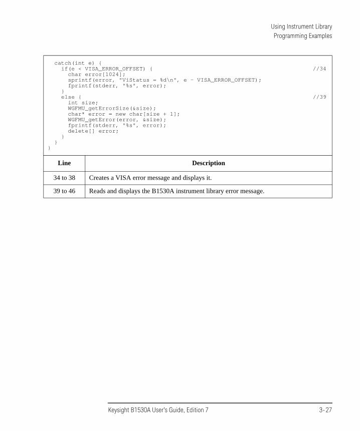
Using Instrument LibraryProgramming Examples
catch(int e) {if(e < VISA_ERROR_OFFSET) { //34
char error[1024];sprintf(error, "ViStatus = %d\n", e - VISA_ERROR_OFFSET);fprintf(stderr, "%s", error);
}else { //39
int size;WGFMU_getErrorSize(&size);char* error = new char[size + 1];WGFMU_getError(error, &size);fprintf(stderr, "%s", error);delete[] error;
}}
}
Line Description
34 to 38 Creates a VISA error message and displays it.
39 to 46 Reads and displays the B1530A instrument library error message.
Keysight B1530A User’s Guide, Edition 7 3-27

Using Instrument LibraryProgramming Examples
Example 11
This program performs sampling measurement by using a SMU, after that performs the measurement almost same as Example 3. The error check is performed by the checkError3 subprogram in the project template shown in Table 3-7. If an error is detected, this program displays the error message. This program requires visa32.lib.
Table 3-18 Programming Example 11
int main() // 1{
try {// OFFLINEcheckError3(WGFMU_clear());checkError3(WGFMU_createPattern("pulse", 0));checkError3(WGFMU_addVector("pulse", 0.0001, 1));checkError3(WGFMU_addVector("pulse", 0.0004, 1));checkError3(WGFMU_addVector("pulse", 0.0001, 0));checkError3(WGFMU_addVector("pulse", 0.0004, 0));checkError3(WGFMU_setMeasureEvent("pulse", "evt", 0, 1000, 1e-6, 0, WGFMU_MEAS
URE_EVENT_DATA_AVERAGED));checkError3(WGFMU_addSequence(101, "pulse", 10));
// ONLINEViSession defaultRM; //15ViSession vi;checkError3(viOpenDefaultRM(&defaultRM) + VISA_ERROR_OFFSET);checkError3(viOpen(defaultRM, "GPIB0::17::INSTR", VI_NULL, VI_NULL, &vi) +
VISA_ERROR_OFFSET);checkError3(WGFMU_openSession("GPIB0::17::INSTR"));checkError3(WGFMU_setTimeout(120));checkError3(viPrintf(vi, "*RST\n") + VISA_ERROR_OFFSET); //21checkError3(WGFMU_initialize());checkError3(WGFMU_setOperationMode(101, WGFMU_OPERATION_MODE_FASTIV));checkError3(viPrintf(vi, "CN 201\n") + VISA_ERROR_OFFSET); //24checkError3(WGFMU_connect(101));checkError3(viPrintf(vi, "MV 201,0,0,5\n") + VISA_ERROR_OFFSET); //26checkError3(viPrintf(vi, "MT 0,1,110,5\n") + VISA_ERROR_OFFSET);checkError3(viPrintf(vi, "MM 10,201\n") + VISA_ERROR_OFFSET);
Line Description
1 to 64 Almost same as Example 3.
15 to 18 Open the session for the SMU installed in the B1500A with the WGFMU.
21 Resets the B1500A.
24 Enables the SMU of the channel number 201.
26 to 28 Sets the sampling measurement condition to the SMU.
3-28 Keysight B1530A User’s Guide, Edition 7

Using Instrument LibraryProgramming Examples
char buffer[2048]; //29checkError3(viPrintf(vi, "ERRX?\n") + VISA_ERROR_OFFSET);checkError3(viScanf(vi, "%t", buffer) + VISA_ERROR_OFFSET);fprintf(stderr, "%s", buffer);checkError3(viPrintf(vi, "XE\n") + VISA_ERROR_OFFSET);checkError3(WGFMU_execute());checkError3(WGFMU_waitUntilCompleted());
int nub; //37checkError3(viPrintf(vi, "NUB?\n") + VISA_ERROR_OFFSET);checkError3(viScanf(vi, "%d%t", &nub, buffer) + VISA_ERROR_OFFSET);fprintf(stderr, "%d\n", nub);checkError3(viScanf(vi, "%t", buffer));fprintf(stderr, "%s", buffer);checkError3(WGFMU_initialize());checkError3(viPrintf(vi, "CL 201\n") + VISA_ERROR_OFFSET); //44checkError3(WGFMU_closeSession());checkError3(viClose(vi) + VISA_ERROR_OFFSET); //46checkError3(viClose(defaultRM) + VISA_ERROR_OFFSET);
}catch(int e) {
if(e < VISA_ERROR_OFFSET) { //50char error[1024];sprintf(error, "ViStatus = %d\n", e - VISA_ERROR_OFFSET);fprintf(stderr, "%s", error);
}else { //55
int size;WGFMU_getErrorSize(&size);char* error = new char[size + 1];WGFMU_getError(error, &size);fprintf(stderr, "%s", error);delete[] error;
}}
}
Line Description
29 to 33 Performs error check and execute the sampling measurement.
37 to 42 Confirms the number of measurement data.
44, 46, 47 Disables the SMU and closes the session for the SMU.
50 to 54 Creates a VISA error message and displays it.
55 to 62 Reads and displays the B1530A instrument library error message.
Keysight B1530A User’s Guide, Edition 7 3-29

Using Instrument LibraryIf You Perform DC Measurement
If You Perform DC MeasurementWGFMU also provides DC voltage output and voltage or current measurement capability. To perform the DC measurement, use the functions listed in Table 3-19.
Table 3-19 To Perform DC Measurement
Step Action Function
Starts error and warning logging a
a. Optional.
WGFMU_openLogFile
1 Opens session WGFMU_openSession
Initializes WGFMU channels a WGFMU_initialize
2 Sets operation mode to DC mode WGFMU_setOperationMode
Sets voltage output range b
b. Optional for changing setup to a new value.
WGFMU_setForceVoltageRange
Sets measurement mode b WGFMU_setMeasureMode
Sets measurement range b WGFMU_setMeasureCurrentRange
WGFMU_setMeasureVoltageRange
3 Enables WGFMU channels WGFMU_connect
Starts DC voltage output b WGFMU_dcforceVoltage
4 Starts voltage or current measurement and returns result
WGFMU_dcmeasureValue
Starts sampling measurement and returns results
WGFMU_dcmeasureAveragedValue
5 Disables WGFMU channels WGFMU_disconnect
6 Closes session WGFMU_closeSession
Stops error and warning logging a WGFMU_closeLogFile
3-30 Keysight B1530A User’s Guide, Edition 7

4 Instrument Library Reference

Instrument Library Reference
This chapter is the complete reference of the Keysight B1530A WGFMU Instrument Library and consists of the following sections.
• “Function Reference”
• “Parameters”
• “Channel Execution Status”
• “WGFMU Setup Functions”
• “Return Codes”
• “Error Messages”
For the summary of the WGFMU instrument library functions, see Table 4-1. The functions are classified by applications.
NOTE About function name
Function name depends on the programming environment as shown below.
• For Microsoft Visual C++ .NET, Visual Basic .NET, Visual Basic 6.0, or VBA:
WGFMU_functionName (ex. WGFMU_abortChannel)
See “Syntax” in “Function Reference”.
• For Microsoft Visual C# .NET:
WGFMU.functionName (ex. WGFMU.abortChannel)
Change the prefix shown in “Syntax” from “WGFMU_” to “WGFMU.”.
• For HTBasic:
Wm_fctnName (ex. Wm_abortch)
See “Using HTBasic” in “Function Reference”.
For receiving the return code of the function, change the prefix from Wm_ to Fnwm_ and execute the function as shown in the following example.
Example:
LONG RetLONG ChidChid = 101Ret = Fnwm_abortch(Chid)
4-2 Keysight B1530A User’s Guide, Edition 7

Instrument Library Reference
Table 4-1 WGFMU Instrument Library Function Summary
Group Function Description
Common - Initialize
WGFMU_openSession Opens or closes the communication session with the B1500A by using the WGFMU instrument library.WGFMU_closeSession
WGFMU_initialize Resets all WGFMU channels.
WGFMU_setTimeout Sets timeout of the present session.
WGFMU_doSelfCalibration Performs the self-calibration for the mainframe and all modules.
WGFMU_doSelfTest Performs the self-test for the mainframe and all modules.
WGFMU_getChannelIdSize Reads the channel id of the WGFMU channels installed in the B1500A connected to the session.WGFMU_getChannelIds
Common - Error and Warning
WGFMU_getErrorSize Reads the next one error string.
WGFMU_getError
WGFMU_getErrorSummarySize Reads the all error string.
WGFMU_getErrorSummary
WGFMU_treatWarningsAsErrors Sets the threshold between warning and error.
WGFMU_setWarningLevel Sets or reads the warning level.
WGFMU_getWarningLevel
WGFMU_getWarningSummarySize Reads the all warning string.
WGFMU_getWarningSummary
WGFMU_openLogFile Opens or closes a file used to log errors and warnings.
WGFMU_closeLogFile
Keysight B1530A User’s Guide, Edition 7 4-3

Instrument Library Reference
Common - Setup
WGFMU_setOperationMode Sets or reads the operation mode of the specified WGFMU channel, Fast IV, PG, DC, or SMU operation mode.WGFMU_getOperationMode
WGFMU_setForceVoltageRange Sets or reads the voltage output range of the specified source channel.
WGFMU_getForceVoltageRange
WGFMU_setMeasureMode Sets or reads the measurement mode, voltage or current measurement mode.
WGFMU_getMeasureMode
WGFMU_setMeasureCurrentRange Sets or reads the current measurement range of the specified measurement channel.
WGFMU_getMeasureCurrentRange
WGFMU_setMeasureVoltageRange Sets or reads the voltage measurement range of the specified measurement channel.
WGFMU_getMeasureVoltageRange
WGFMU_setForceDelay Sets or reads the device delay time of the specified source channel.
WGFMU_getForceDelay
WGFMU_setMeasureDelay Sets or reads the device delay time of the specified measurement channel.
WGFMU_getMeasureDelay
WGFMU_setMeasureEnabled Enables/disables or confirms the measurement ability of the specified WGFMU channel.WGFMU_isMeasureEnabled
WGFMU_setTriggerOutMode Sets or reads the trigger output mode of the specified WGFMU channel.
WGFMU_getTriggerOutMode
Common - Measurement
WGFMU_connect Enables or disables the specified WGFMU channel and the RSU connected to the WGFMU.WGFMU_disconnect
WGFMU - Initialize
WGFMU_clear Clears the instrument library’s software setup information such as all pattern and sequence information.
Group Function Description
4-4 Keysight B1530A User’s Guide, Edition 7

Instrument Library Reference
WGFMU - Setup - Pattern
WGFMU_createPattern Creates a waveform pattern.
WGFMU_addVector Specifies scalar data (time and voltage) and adds it to the specified waveform pattern at the end of pattern.WGFMU_addVectors
WGFMU_setVector Specifies scalar data (time and voltage) and adds it to the specified waveform pattern or replaces the scalar previously defined in the specified waveform pattern with the scalar specified by this function.
WGFMU_setVectors
WGFMU - Setup - Pattern operation
WGFMU_createMergedPattern Creates a waveform pattern by copying a waveform and adding another waveform.
WGFMU_createMultipliedPattern Creates a waveform pattern by copying a waveform and multiplying the waveform by the specified factor.
WGFMU_createOffsetPattern Creates a waveform pattern by copying a waveform and adding the specified offset.
WGFMU - Setup - Event
WGFMU_setMeasureEvent Defines a measurement event which is a sampling measurement performed by the WGFMU channel while it outputs a waveform pattern.
WGFMU_setRangeEvent Defines a range event which is the range change operation for the current measurement performed by the WGFMU channel while it outputs a waveform pattern.
WGFMU_setTriggerOutEvent Defines a trigger output event which is the trigger output operation performed by the WGFMU channel while it outputs a waveform pattern.
WGFMU - Setup - Sequence
WGFMU_addSequence Adds sequence data (pattern and count) to the source output sequence defined in the specified WGFMU channel.WGFMU_addSequences
Group Function Description
Keysight B1530A User’s Guide, Edition 7 4-5

Instrument Library Reference
WGFMU - Setup check - Pattern
WGFMU_getPatternForceValueSize Reads the scalar data (time and voltage) for the source output point defined in the specified pattern.WGFMU_getPatternForceValues
WGFMU_getPatternForceValue
WGFMU_getPatternInterpolatedForceValue
Reads the voltage output value of the specified pattern at the specified time.
WGFMU_getPatternMeasureTimeSize Reads the measurement start time (time) for the measurement point defined in the specified pattern.WGFMU_getPatternMeasureTimes
WGFMU_getPatternMeasureTime
WGFMU - Setup check - Sequence
WGFMU_getForceValueSize Reads the scalar data (time and voltage) for the source output point defined in the sequences set to the specified WGFMU channel.
WGFMU_getForceValues
WGFMU_getForceValue
WGFMU_getInterpolatedForceValue Reads the voltage value applied by the specified WGFMU channel at the specified time.
WGFMU_getMeasureTimeSize Reads the measurement start time (time) for the measurement point defined in the sequences set to the specified WGFMU channel.
WGFMU_getMeasureTimes
WGFMU_getMeasureTime
WGFMU - Setup check - Event
WGFMU_getMeasureEventSize Reads the setup (pattern, event, cycle, loop, count, index, and length) for the measurement event defined in the sequences set to the specified WGFMU channel.
WGFMU_getMeasureEvents
WGFMU_getMeasureEvent
WGFMU_getMeasureEventAttribute Reads the setup parameters (time, points, interval, average, and rdata) of WGFMU_setMeasureEvent.
Group Function Description
4-6 Keysight B1530A User’s Guide, Edition 7

Instrument Library Reference
WGFMU - Measurement
WGFMU_update Updates the setting of all WGFMU channels.
WGFMU_updateChannel Updates the setting of the specified WGFMU channel.
WGFMU_execute Runs the sequencer of all enabled WGFMU channels.
WGFMU_abort Stops the sequencer of all WGFMU channels.
WGFMU_abortChannel Stops the sequencer of the specified WGFMU channel.
WGFMU_getStatus Reads the status of the WGFMU channels.
WGFMU_getChannelStatus Reads the status of the specified WGFMU channel.
WGFMU_waitUntilCompleted Waits until all connected WGFMU channels are in the ready to read data status.
WGFMU - Data retrieve - Measurement value
WGFMU_getMeasureValueSize Reads the measurement data (time and voltage or current) for the measurement point defined in the sequences set to the specified WGFMU channel.
WGFMU_getMeasureValues
WGFMU_getMeasueValue
WGFMU - Data retrieve - Event
WGFMU_getCompletedMeasureEventSize
Reads the number of the measurement events already completed and the total number of the measurement events.
WGFMU_isMeasureEventCompleted Reads the execution status (complete, measId, index, and length) of the specified measurement event setup.
WGFMU - Export setup data
WGFMU_exportAscii Creates a setup summary report and saves it as a csv (comma separated values) file.
Group Function Description
Keysight B1530A User’s Guide, Edition 7 4-7

Instrument Library Reference
DC - Measurement
WGFMU_dcforceVoltage Starts DC voltage output immediately by using the specified WGFMU channel.
WGFMU_dcmeasureValue Starts a voltage or current measurement immediately by using the specified WGFMU channel and returns the measurement value (voltage or current).
WGFMU_dcmeasureAveragedValue Starts a sampling measurement immediately by using the specified WGFMU channel and returns the averaged measurement value (voltage or current).
Group Function Description
4-8 Keysight B1530A User’s Guide, Edition 7

Instrument Library ReferenceFunction Reference
Function ReferenceThis section describes the functions of the WGFMU instrument library. “Syntax” shows the function syntax and “Example” shows an example program code for using the Visual C++ language. “Using HTBasic” shows the function expression for using the HTBasic language. In “Parameters”, the parameters are put in italics such as chanId. The functions are appeared in alphabetical order.
WGFMU_abort
This function stops the sequencer of all WGFMU channels. After this command, the channels keep the output voltage when this command is executed.
Syntax int WGFMU_abort();
Using HTBasic Wm_abort()
Example int ret;ret = WGFMU_abort();
WGFMU_abortChannel
This function stops the sequencer of the specified channel. After this command, the channel keeps the output voltage when this command is executed.
Syntax int WGFMU_abortChannel(int chanId);
Using HTBasic Wm_abortch(chanId)
Parameters chanId : Channel number. Integer. 101 to 1002. See Table 4-3 on page 4-67.
Example int ret;int chId = 101;ret = WGFMU_abortChannel(chId);
WGFMU_addSequence
This function specifies a sequence by using pattern and count, and connects it to the last point of the sequence data set to the specified channel. See “WGFMU Setup Functions” on page 4-77 for the error check of parameters.
Keysight B1530A User’s Guide, Edition 7 4-9

Instrument Library ReferenceFunction Reference
Execution Conditions
Waveform pattern specified by pattern must be created before this function is executed. See WGFMU_createPattern and WGFMU_createXxxPattern to create a pattern data.
Syntax int WGFMU_addSequence(int chanId, const char* pattern, double count);
Using HTBasic Wm_addsequence(chanId, pattern, count)
Parameters chanId : Channel number. Integer. 101 to 1002. See Table 4-3 on page 4-67.
pattern : Name of waveform pattern. String.
count : Repeat count of the waveform pattern. 1 to 1,099,511,627,776. If the specified value is out of this range, the sequence is not added. Numeric.
If the value is not integer, the value is rounded to the nearest integer. For example, if the value is 7.2, the value is rounded to 7.
Example int ret;int chId = 101;const char* ptn = "Pattern1";double cnt = 10;ret = WGFMU_createPattern(ptn, 0); /* 0 ms, 0 V */ret = WGFMU_addVector(ptn, 0.04, 0); /* 40 ms, 0 V */ret = WGFMU_addVector(ptn, 0.01, 5); /* 50 ms, 5 V */ret = WGFMU_addVector(ptn, 0.04, 5); /* 90 ms, 5 V */ret = WGFMU_addVector(ptn, 0.01, 0); /*100 ms, 0 V */ret = WGFMU_addSequence(chId, ptn, cnt);
Remarks If a channel repeats a sequence output, no delay time occurs between the repeats. If a channel outputs sequences in series, 50 ns delay time occurs between the sequences. In the delay time, the channel outputs the last voltage of the last vector for the beginning 10 ns and the start voltage of the next vector for the rest 40 ns.
WGFMU_addSequences
This function specifies sequences by using pattern and count, and connects them to the last point of the sequence data set to the specified channel in the array element order. See “WGFMU Setup Functions” on page 4-77 for the error check of parameters.
Execution Conditions
Waveform pattern specified by pattern must be created before this function is executed. See WGFMU_createPattern and WGFMU_createXxxPattern to create a pattern data.
4-10 Keysight B1530A User’s Guide, Edition 7

Instrument Library ReferenceFunction Reference
Syntax int WGFMU_addSequences(int chanId, const char** pattern, double* count, int size);
Using HTBasic Wm_addsequences(chanId, pattern, count, size, slength)
Parameters chanId : Channel number. Integer. 101 to 1002. See Table 4-3 on page 4-67.
pattern : Name of waveform pattern. String array. Array elements must be corresponding to the count array elements together in the element order.
count : Repeat count of the waveform pattern. Numeric array. Array elements must be corresponding to the pattern array elements together in the element order. The value must be 1 to 1,099,511,627,776. If the specified value is out of this range, the sequences are not added.
If the value is not integer, the value is rounded to the nearest integer. For example, if the value is 7.2, the value is rounded to 7.
size : Array size. Number of array elements for both pattern and count. Integer.
slength : Only for the HTBasic programming environment. Length of string. Integer.
Example int ret;int chId = 101;int size = 3;const char* pts[] = { "Initial", "Pattern1", "Pattern2" };double cts[] = { 1, 5, 5 };ret = WGFMU_addSequences(chId, pts, cts, size);
Remarks If a channel repeats a sequence output, no delay time occurs between the repeats. If a channel outputs sequences in series, 50 ns delay time occurs between the sequences. In the delay time, the channel outputs the last voltage of the last vector for the beginning 10 ns and the start voltage of the next vector for the rest 40 ns.
Notices The following notices are required to use the pattern string array for the HTBasic programming environment and the Visual Basic 6.0 programming environment.
• For the HTBasic programming environment:
Define and use the string array variable as shown below.
LONG Size = 3LONG Slength = 10ALLOCATE Pattern$(Size)[Slength]Pattern$(0)="Initial"Pattern$(1)="Pattern1"Pattern$(2)="Pattern2"
Keysight B1530A User’s Guide, Edition 7 4-11

Instrument Library ReferenceFunction Reference
:Wm_addsequences( ... , Pattern$(0), ... , (size), (Slength))
• For the Visual Basic 6.0 programming environment:
Define and use the string array variable as shown below. Then the VarPtrStringArray function is required. For creating the VarPtrStringArray function, visit http://support.microsoft.com/kb/199824.
Dim size As Longsize = 3ReDim pattern(size) As Stringpattern(0)="Initial"pattern(1)="Pattern1"pattern(2)="Pattern2"
:WGFMU_addSequences( ... , VarPtrStringArray(pattern()), ... , size)
WGFMU_addVector
This function specifies a scalar data by using dTime and voltage, and connects it to the last point of the specified waveform pattern. This adds a vector to the pattern. See “WGFMU Setup Functions” on page 4-77 for the error check of parameters.
Execution Conditions
Waveform pattern specified by pattern must be created before this function is executed. See WGFMU_createPattern and WGFMU_createXxxPattern to create a pattern data.
Syntax int WGFMU_addVector(const char* pattern, double dTime, double voltage);
Using HTBasic Wm_addvector(pattern, dTime, voltage)
Parameters pattern : Name of waveform pattern to add a vector. String.
dTime : Incremental time value, in second. Numeric.
10-8 (10 ns) to 10995.11627775 seconds, in 10-8 second resolution. If the specified value is out of this range, the vector is not added.
If the value is not multiple number of 10 ns, the value is rounded to the nearest multiple number. For example, if the value is 72 ns, the value is rounded to 70 ns.
voltage : Output voltage, in V. Numeric. See Table 4-2 on page 4-66.
4-12 Keysight B1530A User’s Guide, Edition 7

Instrument Library ReferenceFunction Reference
Example int ret;const char* ptn = "Pattern2";ret = WGFMU_createPattern(ptn, 0); /* 0 ms, 0 V */ret = WGFMU_addVector(ptn, 0.01, 0); /* 10 ms, 0 V */ret = WGFMU_addVector(ptn, 0.01, -5); /* 20 ms,-5 V */ret = WGFMU_addVector(ptn, 0.03, -5); /* 50 ms,-5 V */ret = WGFMU_addVector(ptn, 0.01, 5); /* 60 ms, 5 V */ret = WGFMU_addVector(ptn, 0.03, 5); /* 90 ms, 5 V */ret = WGFMU_addVector(ptn, 0.01, 0); /*100 ms, 0 V */
WGFMU_addVectors
This function specifies multiple scalar data by using dTime and voltage, and connects them to the last point of the specified waveform pattern in the array element order. This adds vectors to the pattern. See “WGFMU Setup Functions” on page 4-77 for the error check of parameters.
Execution Conditions
Waveform pattern specified by pattern must be created before this function is executed. See WGFMU_createPattern and WGFMU_createXxxPattern to create a pattern data.
Syntax int WGFMU_addVectors(const char* pattern, double* dTime, double* voltage, int size);
Using HTBasic Wm_addvectors(pattern, dTime, voltage, size)
Parameters pattern : Name of waveform pattern to add vectors. String.
dTime : Incremental time value, in second. Numeric array. Array elements must be corresponding to the voltage array elements together in the element order.
The value must be 10-8 (10 ns) to 10995.11627775 seconds, in 10-8 second resolution. If the specified value is out of this range, the vectors are not added.
If the value is not multiple number of 10 ns, the value is rounded to the nearest multiple number. For example, if the value is 72 ns, the value is rounded to 70 ns.
voltage : Output voltage, in V. See Table 4-2 on page 4-66. Numeric array. Array elements must be corresponding to the dTime array elements together in the element order.
size : Array size. Number of array elements for both dTime and voltage. Integer.
Keysight B1530A User’s Guide, Edition 7 4-13

Instrument Library ReferenceFunction Reference
Example int ret;int size = 4;const char* ptn = "Pattern3";double* dts = new double[size];double* vts = new double[size];dts[0] = dts[1] = dts[2] = dts[3] = 0.1;vts[0] = vts[3] = 0;vts[1] = vts[2] = 5;ret = WGFMU_createPattern(ptn, 0);ret = WGFMU_addVectors(ptn, dts, vts, size);delete [] dts;delete [] vts;
WGFMU_clear
This function clears the instrument library’s software setup information such as all pattern and sequence information, error, error summary, warning, warning summary, warning level, warning level for the WGFMU_treatWarningsAsErrors function.
This function does not change the hardware status.
Syntax int WGFMU_clear();
Using HTBasic Wm_clear()
Example int ret;ret = WGFMU_clear();
WGFMU_closeLogFile
This function closes the log file opened by the WGFMU_openLogFile function.
Syntax int WGFMU_closeLogFile();
Using HTBasic Wm_closelogfile()
Example int ret;const char* fname = "C:¥¥Keysight¥¥B1530A¥¥log¥¥20080901.log";ret = WGFMU_openLogFile(fname);// :ret = WGFMU_closeLogFile();
WGFMU_closeSession
This function closes the session (communication with B1500A) opened by the WGFMU_openSession function.
Syntax int WGFMU_closeSession();
4-14 Keysight B1530A User’s Guide, Edition 7

Instrument Library ReferenceFunction Reference
Using HTBasic Wm_closesession()
Example int ret;const char* addr1 = "GPIB0::17::INSTR";ret = WGFMU_openSession(addr1);// :ret = WGFMU_closeSession();
WGFMU_connect
This function enables the specified WGFMU channel and the RSU connected to the WGFMU.
Syntax int WGFMU_connect(int chanId);
Using HTBasic Wm_connect(chanId)
Parameters chanId : Channel number. Integer. 101 to 1002. See Table 4-3 on page 4-67.
Example int ret;int chId = 101;ret = WGFMU_connect(chId);
WGFMU_createMergedPattern
This function creates a waveform pattern by copying the waveform specified by pattern1 and adding the waveform specified by pattern2. See “WGFMU Setup Functions” on page 4-77 for the error check of parameters.
Execution Conditions
Waveform patterns specified by pattern1 and pattern2 must be created before this function is executed. See WGFMU_createPattern and WGFMU_createXxxPattern to create a pattern data.
Syntax int WGFMU_createMergedPattern(const char* pattern, const char* pattern1, const char* pattern2, int direction);
Using HTBasic Wm_createmgdpt(pattern, pattern1, pattern2, direction)
Parameters pattern : Name of waveform pattern to create. String. Name must be unique. However, the same value as pattern1 or pattern2 is allowed.
pattern1 : Name of waveform pattern to be copied. String. Same value as pattern or pattern2 is allowed.
pattern2 : Name of waveform pattern to be added. String. Same value as pattern or pattern1 is allowed.
Keysight B1530A User’s Guide, Edition 7 4-15

Instrument Library ReferenceFunction Reference
direction : Direction to add waveform pattern. Integer. See Table 4-12 on page 4-74.
Example int ret;const char* ptn = "Pattern5";const char* ptn0 = "Pattern1";const char* ptn1 = "Pattern2";ret = WGFMU_createMergedPattern(ptn, ptn0, ptn1, WGFMU_AXIS_TIME);
NOTE Event settings by this function with direction=WGFMU_AXIS_VOLTAGE
The pattern2 event settings delete and overwrite the pattern1 event settings of the same event type in the same time frame. For example, the pattern2 measurement event settings delete and overwrite the pattern1 measurement event settings in the same time frame, but do not delete the pattern1 range change event settings and the pattern1 trigger output event settings.
WGFMU_createMultipliedPattern
This function creates a waveform pattern by copying the waveform specified by pattern1 and multiplying the waveform by the specified factor for each direction; time and voltage. See “WGFMU Setup Functions” on page 4-77 for the error check of parameters.
Execution Conditions
Waveform pattern specified by pattern1 must be created before this function is executed. See WGFMU_createPattern and WGFMU_createXxxPattern to create a pattern data.
Syntax int WGFMU_createMultipliedPattern(const char* pattern, const char* pattern1, double factorT, double factorV);
Using HTBasic Wm_creatempdpt(pattern, pattern1, factorT, factorV)
Parameters pattern : Name of waveform pattern to be created. String. Name must be unique. However, the same value as pattern1 is allowed.
pattern1 : Name of waveform pattern to be copied. String. Same value as pattern is allowed.
factorT : Multiplier factor in the time direction. Numeric. Non zero value. Event attributes are changed by factorT. See following NOTE.
factorV : Multiplier factor in the voltage direction. Numeric. Non zero value. Event attributes are not changed by factorV.
4-16 Keysight B1530A User’s Guide, Edition 7

Instrument Library ReferenceFunction Reference
Example int ret;const char* ptn = "Pattern6";const char* ptn0 = "Pattern1";double ftime = 2;double fvolt = 2;ret = WGFMU_createMultipliedPattern(ptn, ptn0, ftime, fvolt);
NOTE Measurement event attributes changed by factorT
Event attributes time, interval, and avgTime are multiplied by factorT. The measPts attribute is not changed.
NOTE Range change event attributes changed by factorT
Event attribute time is multiplied by factorT. The rngIndex attribute is not changed.
NOTE Trigger output event attributes changed by factorT
Event attributes time and duration are multiplied by factorT.
NOTE For the negative factorT
If factorT < 0, this function creates a new pattern by calculating the line symmetry of the copied pattern and multiplying it by | factorT |. Then the axis of symmetry is the voltage axis placed on the center of the copied pattern.
The time value newTime of the measurement event for the new pattern is calculated by the following formula.
newTime = pattern1 period - time - interval (measPts-1) - avgTime
For example, if time=100 ns, measPts=4, interval=50 ns, avgTime=30 ns, and pattern1 period=500 ns, the inverted time value newTime is 220 ns.
By the line symmetry, the first point of a pattern will become the last point of the new pattern. Also, the averaging end of a measurement point will become the averaging start of the point on the new pattern. So the measurement start time of the new pattern will be the inversion of the averaging end of the last measurement point. The start time of each measurement point will be automatically adjusted.
WGFMU_createOffsetPattern
This function creates a waveform pattern by copying the waveform specified by pattern1 and adding the specified offset for each direction; time and voltage. See “WGFMU Setup Functions” on page 4-77 for the error check of parameters.
Keysight B1530A User’s Guide, Edition 7 4-17

Instrument Library ReferenceFunction Reference
Execution Conditions
Waveform pattern specified by pattern1 must be created before this function is executed. See WGFMU_createPattern and WGFMU_createXxxPattern to create a pattern data.
Syntax int WGFMU_createOffsetPattern(const char* pattern, const char* pattern1, double offsetT, double offsetV);
Using HTBasic Wm_createostpt(pattern, pattern1, offsetT, offsetV)
Parameters pattern : Name of waveform pattern to be created. String. Name must be unique. However, the same value as pattern1 is allowed.
pattern1 : Name of waveform pattern to be copied. String. Same value as pattern is allowed.
offsetT : Offset value in the time direction, in second. Numeric. Event attribute time is changed by offsetT. The value will be time + offsetT.
offsetV : Offset value in the voltage direction, in V. Numeric. See Table 4-2 on page 4-66. Event attributes are not changed by offsetV.
For the positive offsetT, the copied pattern will be shifted to the positive direction, and a vector with the initial voltage will be inserted at the beginning of the pattern.
For the negative offsetT, the copied pattern will be shifted to the negative direction. Then the vectors before offsetT will be deleted and the time offsetT will become the time origin. At the end of the pattern, no vector is added.
Example int ret;const char* ptn = "Pattern7";const char* ptn0 = "Pattern1";double otime = 1;double ovolt = -2;ret = WGFMU_createOffsetPattern(ptn, ptn0, otime, ovolt);
WGFMU_createPattern
This function creates a waveform pattern. See “WGFMU Setup Functions” on page 4-77 for the error check of parameters.
Syntax int WGFMU_createPattern(const char* pattern, double initV);
Using HTBasic Wm_creatept(pattern, initV)
Parameters pattern : Name of waveform pattern. String. Name must be unique.
4-18 Keysight B1530A User’s Guide, Edition 7

Instrument Library ReferenceFunction Reference
initV : Voltage value for the start point of the pattern, in V. Numeric. See Table 4-2 on page 4-66. This value is voltage for the time origin (0 s) of the pattern.
Example int ret;ret = WGFMU_createPattern("Pattern0", 0);
WGFMU_dcforceVoltage
This function starts DC voltage output immediately by using the specified channel.
Error occurs if the specified channel is not in the DC mode. The operation mode is set by the WGFMU_setOperationMode function.
Syntax int WGFMU_dcforceVoltage(int chanId, double voltage);
Using HTBasic Wm_dcforcevol(chanId, voltage)
Parameters chanId : Channel number. Integer. 101 to 1002. See Table 4-3 on page 4-67.
voltage : Voltage value, in V. Numeric. See Table 4-2 on page 4-66.
Example int ret;int chId = 101;double dcvol = 5;ret = WGFMU_dcforceVoltage(chId, dcvol);
Remarks The WGFMU_dcforceVoltage, WGFMU_dcmeasureAveragedValue, and WGFMU_dcmeasureValue functions apply the setup of the following function to the channel.
• WGFMU_setOperationMode
• WGFMU_setForceVoltageRange
• WGFMU_setMeasureCurrentRange
• WGFMU_setMeasureVoltageRange
• WGFMU_setMeasureMode
WGFMU_dcmeasureAveragedValue
This function starts a sampling measurement immediately by using the specified channel and returns the averaged measurement voltage or current. The measurement mode is set by the WGFMU_setMeasureMode function.
Keysight B1530A User’s Guide, Edition 7 4-19

Instrument Library ReferenceFunction Reference
Error occurs if the specified channel is not in the DC mode. The operation mode is set by the WGFMU_setOperationMode function.
Syntax int WGFMU_dcmeasureAveragedValue(int chanId, int points, int interval, double* value);
Using HTBasic Wm_dcmeasureave(chanId, points, interval, value)
Parameters chanId : Channel number. Integer. 101 to 1002. See Table 4-3 on page 4-67.
points : Number of sampling points. Integer. 1 to 65535.
interval : Sampling interval. Integer. 1 to 65535. The channel sets the sampling interval given by the following formula.
sampling interval = interval 5 ns
value : Numeric pointer to receive the measured value, in V or A.
Example int ret;int chId = 101;int count = 5;int interval = 2;double mVal;ret = WGFMU_dcmeasureAveragedValue(chId, count, interval, &mVal);
WGFMU_dcmeasureValue
This function starts a voltage or current measurement immediately by using the specified channel and returns the measurement value.
Error occurs if the specified channel is not in the DC mode. The operation mode is set by the WGFMU_setOperationMode function.
Syntax int WGFMU_dcmeasureValue(int chanId, double* value);
Using HTBasic Wm_dcmeasureval(chanId, value)
Parameters chanId : Channel number. Integer. 101 to 1002. See Table 4-3 on page 4-67.
value : Numeric pointer to receive the measured value, in V or A.
Example int ret;int chId = 101;double mVal;ret = WGFMU_dcmeasureValue(chId, &mVal);
4-20 Keysight B1530A User’s Guide, Edition 7

Instrument Library ReferenceFunction Reference
WGFMU_disconnect
This function disables the specified WGFMU channel and the RSU.
Syntax int WGFMU_disconnect(int chanId);
Using HTBasic Wm_disconnect(chanId)
Parameters chanId : Channel number. Integer. 101 to 1002. See Table 4-3 on page 4-67.
Example int ret;int chId = 101;ret = WGFMU_disconnect(chId);
WGFMU_doSelfCalibration
This function performs the self-calibration for the mainframe and all modules.
Syntax int WGFMU_doSelfCalibration(int* result, char* detail, int* size);
Using HTBasic Wm_doselfcal(result, detail, size)
Parameters result : Integer pointer to receive the self-calibration result. The following response will be returned. If multiple failures are detected, the returned value will be sum of responses. For example, if failures are detected in the slot 2 and 3 modules, 6 (21+22) is returned.
0: Mainframe and all modules passed self-calibration.
2N-1: Slot N module failed self-calibration.
210 (1024): Mainframe failed self-calibration.
detail : String pointer to receive the self-calibration result detail string. The string size must be longer than the length of the detail string.
size : Integer pointer to specify the number of characters to read as the self-calibration result detail string. Error occurs if the specified size value is negative or 0.
If the specified size value is greater than or equal to the length of the detail string, all of the detail string is stored in detail. And this pointer returns the length of the detail string.
Keysight B1530A User’s Guide, Edition 7 4-21

Instrument Library ReferenceFunction Reference
If the specified size value is less than the length of the detail string, a part of the detail string is stored in detail and a warning occurs. Then the number of characters stored in detail is size.
Example int ret;int result;char* detail;int size = 256;detail = new char[size + 1];ret = WGFMU_doSelfCalibration(&result, detail, &size);// delete [] after required process is completed
WGFMU_doSelfTest
This function performs the self-test for the mainframe and all modules.
Syntax int WGFMU_doSelfTest(int* result, char* detail, int* size);
Using HTBasic Wm_doselftest(result, detail, size)
Parameters result : Integer pointer to receive the self-test result. The following response will be returned. If multiple failures are detected, the returned value will be sum of responses. For example, if failures are detected in the slot 1 and 2 modules, 3 (20+21) is returned.
0: Mainframe and all modules passed self-test.
2N-1: Slot N module failed self-test.
210 (1024): Mainframe failed self-test.
detail : String pointer to receive the self-test result detail string. The string size must be longer than the length of the detail string.
size : Integer pointer to specify the number of characters to read as the self-test result detail string. Error occurs if the specified size value is negative or 0.
If the specified size value is greater than or equal to the length of the detail string, all of the detail string is stored in detail. And this pointer returns the length of the detail string.
If the specified size value is less than the length of the detail string, a part of the detail string is stored in detail and a warning occurs. Then the number of characters stored in detail is size.
4-22 Keysight B1530A User’s Guide, Edition 7

Instrument Library ReferenceFunction Reference
Example int ret;int result;char* detail;int size = 256;detail = new char[size + 1];ret = WGFMU_doSelfTest(&result, detail, &size);// delete [] after required process is completed
WGFMU_execute
This function runs the sequencer of all enabled WGFMU channels in the Fast IV mode or the PG mode. The channels start the predefined operation. If there are channels in the run status, this function stops the sequencers and runs the sequencer of all enabled WGFMU channels. After the execution, the channels keep the last output voltage.
This function applies the setup of the following function to the channel.
• WGFMU_setOperationMode
• WGFMU_setForceVoltageRange
• WGFMU_setMeasureCurrentRange
• WGFMU_setMeasureVoltageRange
• WGFMU_setMeasureMode
Syntax int WGFMU_execute();
Using HTBasic Wm_execute()
Example int ret;ret = WGFMU_execute();
WGFMU_exportAscii
This function creates a setup summary report and saves it as a csv (comma separated values) file. The summary report contains the pattern data, event data, and sequence data for the channels configured by the instrument library. The file can be read by using a spreadsheet software. This is effective for quick debugging. See Figure 4-1 for example data.
If the specified file does not exist, this function creates new file. If the specified file exists, this function overwrites the file. Error occurs if an invalid path is specified, a file is not created, or a setup summary is not written.
Syntax int WGFMU_exportAscii(const char* file);
Keysight B1530A User’s Guide, Edition 7 4-23

Instrument Library ReferenceFunction Reference
Using HTBasic Wm_exportascii(file)
Parameters file : Name of the summary report file. The file extension will be csv if you do not specify it.
Example int ret;const char* fname = "C:¥¥Keysight¥¥B1530A¥¥setup¥¥summary1.csv";ret = WGFMU_exportAscii(fname);
Figure 4-1 WGFMU_exportAscii Output Example
4-24 Keysight B1530A User’s Guide, Edition 7

Instrument Library ReferenceFunction Reference
WGFMU_getChannelIds
This function reads the channel id of the WGFMU channels installed in the B1500A connected to this session. To know the number of WGFMU channels, execute the WGFMU_getChannelIdSize function.
Syntax int WGFMU_getChannelIds(int* result, int* size);
Using HTBasic Wm_getchids(result, size)
Parameters result : Integer array pointer to receive the channel id. Array size must be greater than or equal to the actual number of WGFMU channels.
size : Integer pointer to specify the number of WGFMU channel id to read. Error occurs if the specified size value is negative or 0.
If the specified size value is greater than or equal to the actual number of WGFMU channels, all of the channel id is stored in result. And this pointer returns the actual number of WGFMU channels.
If the specified size value is less than the actual number of WGFMU channels, some of channel id is stored in result and a warning occurs. Then the number of channel id stored in result is size.
WGFMU_getChannelIdSize
This function returns the number of WGFMU channels installed in the B1500A connected to this session.
Syntax int WGFMU_getChannelIdSize(int* size);
Using HTBasic Wm_getchidsz(size)
Parameters size : Integer pointer to receive the number of WGFMU channels.
Example int ret;int size = 1;ret = WGFMU_getChannelIdSize(&size);int* rId = new int[size];ret = WGFMU_getChannelIds(rId, &size);// delete [] after required process is completed
WGFMU_getChannelStatus
This function returns the status of the specified channel in the Fast IV mode or the PG mode. See “Channel Execution Status” on page 4-76 for the returned time data.
Keysight B1530A User’s Guide, Edition 7 4-25

Instrument Library ReferenceFunction Reference
Syntax int WGFMU_getChannelStatus(int chanId, int* status, double* elapsT, double* totalT);
Using HTBasic Wm_getchstatus(chanId, status, elapsT, totalT)
Parameters chanId : Channel number. Integer. 101 to 1002. See Table 4-3 on page 4-67.
status : Integer pointer to receive the status shown in Table 4-17 on page 4-79.
elapsT : Numeric pointer to receive the estimated elapsed time, in second.
totalT : Numeric pointer to receive the estimated total time until all sequences are completed, in second.
Example int ret;int chId = 101;int stat;double elapsT;double totalT;ret = WGFMU_getChannelStatus(chId, &stat, &elapsT, &totalT);
WGFMU_getCompletedMeasureEventSize
This function returns the number of completed measurement events and the total number of measurement events set to the specified channel. See “Channel Execution Status” on page 4-76.
Syntax int WGFMU_getCompletedMeasureEventSize(int chanId, int* complete, int* total);
Using HTBasic Wm_getcdmeevtsz(chanId, complete, total)
Parameters chanId : Channel number. Integer. 101 to 1002. See Table 4-3 on page 4-67.
complete : Integer pointer to receive the number of the measurement events which have been already completed.
total : Integer pointer to receive the total number of the measurement events.
Example int ret;int chId = 101;int comp = 1;int ttl = 1;do {
ret = WGFMU_getCompletedMeasureEventSize(chId, &comp, &ttl);} while ( comp < ttl );
4-26 Keysight B1530A User’s Guide, Edition 7

Instrument Library ReferenceFunction Reference
WGFMU_getError
This function reads one error string. To know the length of the next error string, execute the WGFMU_getErrorSize function. The error string is cleared by the WGFMU_clear function.
Syntax int WGFMU_getError(char* result, int* size);
Using HTBasic Wm_geterr(result, size)
Parameters result : String pointer to receive one error string. The string size must be longer than the length of the next error string.
size : Integer pointer to specify the number of characters to read as the error string. Error occurs if the specified size value is 0 or negative.
If the specified size value is greater than or equal to the length of the error string, all of the error string is stored in result. And this pointer returns the length of the error string.
If the specified size value is less than the length of the error string, a part of the error string is stored in result and a warning occurs. Then the number of characters stored in result is size.
WGFMU_getErrorSize
This function returns the length of the next error string.
Syntax int WGFMU_getErrorSize(int* size);
Using HTBasic Wm_geterrsz(size)
Parameters size : Integer pointer to receive the length of the next error string.
Example int checkErrorFlag = 1;void checkError(int ret) {
if(checkErrorFlag != 0) {if(ret != WGFMU_NO_ERROR) {
int size = 1;WGFMU_getErrorSize(&size);char* msg = new char[size + 1];WGFMU_getError(msg, &size);// do something with msg// delete [] after required process is completed
}}
}int main()
Keysight B1530A User’s Guide, Edition 7 4-27

Instrument Library ReferenceFunction Reference
{int ret;const char* fname = "C:¥¥Keysight¥¥B1530A¥¥setup¥¥summary1.csv";ret = WGFMU_exportAscii(fname);checkError(ret);}
WGFMU_getErrorSummary
This function reads the error summary string which contains all errors. To know the length of the error summary string, execute the WGFMU_getErrorSummarySize function. The error summary string is cleared by the WGFMU_clear function.
Syntax int WGFMU_getErrorSummary(char* result, int* size);
Using HTBasic Wm_geterrsum(result, size)
Parameters result : String pointer to receive the error summary string. The string size must be longer than the length of the error summary string.
size : Integer pointer to specify the number of characters to read as the error summary string. Error occurs if the specified size value is 0 or negative.
If the specified size value is greater than or equal to the length of the error summary string, all of the error summary string is stored in result. And this pointer returns the length of the error summary string.
If the specified size value is less than the length of the error summary string, a part of the error summary string is stored in result and a warning occurs. Then the number of characters stored in result is size.
WGFMU_getErrorSummarySize
This function returns the length of the error summary string which contains all errors.
Syntax int WGFMU_getErrorSummarySize(int* size);
Using HTBasic Wm_geterrsumsz(size)
Parameters size : Integer pointer to receive the length of the error summary string.
Example int size = 1;WGFMU_getErrorSummarySize(&size);if (size != 0) {
char* msg = new char[size + 1];WGFMU_getErrorSummary(msg, &size);
4-28 Keysight B1530A User’s Guide, Edition 7

Instrument Library ReferenceFunction Reference
// do something with msg// delete [] after required process is completed
}
WGFMU_getForceDelay
This function returns the device delay time of the specified source channel in the Fast IV mode or the PG mode.
Syntax int WGFMU_getForceDelay(int chanId, double* delay);
Using HTBasic Wm_getfodelay(chanId, delay)
Parameters chanId : Channel number. Integer. 101 to 1002. See Table 4-3 on page 4-67.
delay : Numeric pointer to receive the device delay time, in second.
delay must be -5010-9 (-50 ns) to 5010-9 (50 ns), in 62510-12 (625 ps) resolution.
If the value is not multiple number of 625 ps, the value is rounded to the nearest multiple number. For example, if the value is 1.5 ns, the value is rounded to 1.25 ns.
Example int ret;int chId = 101;double fDelay;ret = WGFMU_getForceDelay(chId, &fDelay);
WGFMU_getForceValue
This function specifies a channel and an index of sequence data, and returns the corresponding setup data (time and voltage).
Syntax int WGFMU_getForceValue(int chanId, double index, double* time, double* voltage);
Using HTBasic Wm_getfoval(chanId, index, time, voltage)
Parameters chanId : Channel number. Integer. 101 to 1002. See Table 4-3 on page 4-67.
index : Index of the sequence data to read setup. Numeric. index must be 0 to the total number of setup data -1. Error occurs if the value is out of this range.
time : Numeric pointer to receive the time data, in second.
voltage : Numeric pointer to receive the voltage data, in V.
Keysight B1530A User’s Guide, Edition 7 4-29

Instrument Library ReferenceFunction Reference
Example int ret;int chId = 101;double dsize = 1;ret = WGFMU_getForceValueSize(chId, &dsize);int size = int(dsize);double* dTime = new double[size];double* volt = new double[size];for (int i = 0; i < size; i++){
ret = WGFMU_getForceValue(chId, i, &dTime[i], &volt[i]);}
WGFMU_getForceValues
This function specifies a channel and a range of sequence data, and returns the corresponding setup data (time and voltage). To know the total number of setup data, execute the WGFMU_getForceValueSize function.
Syntax int WGFMU_getForceValues(int chanId, double index, int* length, double* time, double* voltage);
Using HTBasic Wm_getfovals(chanId, index, length, time, voltage)
Parameters chanId : Channel number. Integer. 101 to 1002. See Table 4-3 on page 4-67.
index : First index of the sequence data to read setup. Numeric. index must be 0 to the total number of setup data -1. Error occurs if the value is out of this range.
length : Integer pointer to specify the number of setup data to read and receive the number of data returned. length must be 1 to the total number of setup data - index. If length is greater than this value, all of the returned data is stored in time and voltage and a warning occurs. Error occurs if length is less than 1.
time : Numeric array pointer to receive the time data, in second.
voltage : Numeric array pointer to receive the voltage data, in V.
For the array pointers, the array size must be length.
Example int ret;int chId = 101;double dsize = 1;ret = WGFMU_getForceValueSize(chId, &dsize);int size = int(dsize);double* dTime = new double[size];double* volt = new double[size];ret = WGFMU_getForceValues(chId, 0, &size, dTime, volt);
4-30 Keysight B1530A User’s Guide, Edition 7

Instrument Library ReferenceFunction Reference
WGFMU_getForceValueSize
This function returns the total number of setup data (time and voltage) defined in the source output sequence set to the specified channel.
Syntax int WGFMU_getForceValueSize(int chanId, double* size);
Using HTBasic Wm_getfovalsz(chanId, size)
Parameters chanId : Channel number. Integer. 101 to 1002. See Table 4-3 on page 4-67.
size : Numeric pointer to receive the total number of setup data.
Example int ret;int chId = 101;double dsize = 1;ret = WGFMU_getForceValueSize(chId, &dsize);
WGFMU_getForceVoltageRange
This function returns the voltage output range set to the specified channel. The value is set by the WGFMU_setForceVoltageRange function. The setting is applied to the channel by the WGFMU_update, WGFMU_updateChannel, WGFMU_execute, or the functions of the DC measurement group.
Syntax int WGFMU_getForceVoltageRange(int chanId, int* range);
Using HTBasic Wm_getfovolrng(chanId, range)
Parameters chanId : Channel number. Integer. 101 to 1002. See Table 4-3 on page 4-67.
range : Integer pointer to receive the voltage output range. See Table 4-6 on page 4-70.
Example int ret;int chId = 101;int fRange;ret = WGFMU_getForceVoltageRange(chId, &fRange);
WGFMU_getInterpolatedForceValue
This function specifies a channel and a time value (time), and returns the voltage value (voltage) applied by the specified WGFMU channel at the specified time. The returned value may be the value given by the interpolation.
Keysight B1530A User’s Guide, Edition 7 4-31
Instrument Library ReferenceFunction Reference
Syntax int WGFMU_getInterpolatedForceValue(int chanId, double time, double* voltage);
Using HTBasic Wm_getidfoval(chanId, time, voltage)
Parameters chanId : Channel number. Integer. 101 to 1002. See Table 4-3 on page 4-67.
time : Time to read the voltage output value, in second. Numeric. time must be 0 to the length of the waveform set to the specified channel. Error occurs if the value is out of this range.
voltage : Numeric pointer to receive the voltage output value, in V.
Example int ret;int chId = 101;double reTm = 1E-6;double volt;ret = WGFMU_getInterpolatedForceValue(chId, reTm, &volt);
WGFMU_getMeasureCurrentRange
This function returns the current measurement range set to the specified channel. The value is set by the WGFMU_setMeasureCurrentRange function. The setting is applied to the channel by the WGFMU_update, WGFMU_updateChannel, WGFMU_execute, or the functions of the DC measurement group. The setting is not effective for the voltage measurement mode.
Syntax int WGFMU_getMeasureCurrentRange(int chanId, int* range);
Using HTBasic Wm_getmecurrng(chanId, range)
Parameters chanId : Channel number. Integer. 101 to 1002. See Table 4-3 on page 4-67.
range : Integer pointer to receive the current measurement range. See Table 4-9 on page 4-72.
Example int ret;int chId = 101;int mRange;ret = WGFMU_getMeasureCurrentRange(chId, &mRange);
WGFMU_getMeasureDelay
This function returns the device delay time of the specified measurement channel in the Fast IV mode or the PG mode.
4-32 Keysight B1530A User’s Guide, Edition 7

Instrument Library ReferenceFunction Reference
Syntax int WGFMU_getMeasureDelay(int chanId, double* delay);
Using HTBasic Wm_getmedelay(chanId, delay)
Parameters chanId : Channel number. Integer. 101 to 1002. See Table 4-3 on page 4-67.
delay : Numeric pointer to receive the device delay time, in second.
delay must be -5010-9 (-50 ns) to 5010-9 (50 ns), in 62510-12 (625 ps) resolution.
If the value is not multiple number of 625 ps, the value is rounded to the nearest multiple number. For example, if the value is 1.5 ns, the value is rounded to 1.25 ns.
Example int ret;int chId = 101;double mDelay;ret = WGFMU_getMeasureDelay(chId, &mDelay);
WGFMU_getMeasureEvent
This function specifies a channel and an index of measurement event, and returns the corresponding setup (pattern, event, cycle, loop, count, index, and length).
Syntax int WGFMU_getMeasureEvent(int chanId, int measId, const char* pattern, const char* event, int* cycle, double* loop, int* count, int* index, int* length);
Using HTBasic Wm_getmeevt(chanId, measId, pattern, event, cycle, loop, count, index, length)
Parameters chanId : Channel number. Integer. 101 to 1002. See Table 4-3 on page 4-67.
measId : Index of the measurement event to read setup. Integer. measId must be 0 to the total number of measurement events -1. Error occurs if the value is out of this range.
pattern : String pointer to receive the waveform pattern name.
event : String pointer to receive the event name.
cycle : Integer pointer to receive the usage count. This parameter means how many times the pattern is used in the sequence of the specified channel.
loop : Numeric pointer to receive the loop count. This parameter means how many times the pattern is looped in the sequence of the specified channel.
Keysight B1530A User’s Guide, Edition 7 4-33

Instrument Library ReferenceFunction Reference
count : Integer pointer to receive the event count. This parameter means how many times the event is used in the pattern.
index : Integer pointer to receive the first data index assigned to the specified measurement event.
length : Integer pointer to receive the number of sampling points for the specified measurement event.
Example int ret; int chId = 101;int measId = 0;int size = 1;ret = WGFMU_getMeasureEventSize(chId, &size);int stringSize = 512;char** ptn = new char*[size];char** evt = new char*[size];for (int i = 0; i < size; i++){
ptn[i] = new char[stringSize];evt[i] = new char[stringSize];
}int* cycle = new int[size];double* loop = new double[size];int* count = new int[size];int* idx = new int[size];int* len = new int[size];for (int i = measId; i < measId + size; i++){
ret = WGFMU_getMeasureEvent(chId, i, ptn[i], evt[i], &cycle[i], &loop[i], &count[i], &idx[i], &len[i]);}// delete [] after required process is completed
WGFMU_getMeasureEventAttribute
This function specifies a channel and a measurement event index, and returns the corresponding measurement event attribute (time, points, interval, average, and rdata) which have been set by the WGFMU_setMeasureEvent function.
Syntax int WGFMU_getMeasureEventAttribute(int chanId, int measId, double* time, int* points, double* interval, double* average, int* rdata);
Using HTBasic Wm_getmeevtattr(chanId, measId, time, points, interval, average, rdata)
Parameters chanId : Channel number. Integer. 101 to 1002. See Table 4-3 on page 4-67.
measId : Measurement event index. Integer. For instance, the index can be read by WGFMU_isMeasureEventCompleted.
4-34 Keysight B1530A User’s Guide, Edition 7

Instrument Library ReferenceFunction Reference
time : Numeric pointer to receive the measurement start time in the pattern, in second.
points : Integer pointer to receive the number of sampling points.
interval : Numeric pointer to receive the sampling interval, in second.
average : Numeric pointer to receive the averaging time, in second.
rdata : Integer pointer to receive rdata value of WGFMU_setMeasureEvent.
Example int ret;int chId = 101;const char* ptn = "Pattern1";const char* evt = "Event1";int cycle = 0;double loop = 0;int count = 0;int cmp;int measId;int idx;int len;ret = WGFMU_isMeasureEventCompleted(chId, ptn, evt, cycle, loop, count, &cmp, &measId, &idx, &len); double sTime;int pts;double tInt;double tAve;int rdat;ret = WGFMU_getMeasureEventAttribute(chId, measId, &sTime, &pts, &tInt, &tAve, &rdat);
WGFMU_getMeasureEvents
This function specifies a channel and a range of measurement events, and returns the corresponding setup (pattern, event, cycle, loop, count, index, and length). To know the total number of events, execute the WGFMU_getMeasureEventSize function.
Syntax int WGFMU_getMeasureEvents(int chanId, int measId, int* eventsNo, const char** pattern, const char** event, int* cycle, double* loop, int* count, int* index, int* length);
Using HTBasic Wm_getmeevts(chanId, measId, eventsNo, pattern, event, cycle, loop, count, index, length, slength)
Parameters chanId : Channel number. Integer. 101 to 1002. See Table 4-3 on page 4-67.
measId : First index of the measurement events to read setup. Integer. measId must be 0 to the total number of measurement events -1. Error occurs if the value is out of this range.
Keysight B1530A User’s Guide, Edition 7 4-35

Instrument Library ReferenceFunction Reference
eventsNo : Integer pointer to specify the number of measurement events to read setup and receive the number of events returned. eventsNo must be 1 to the total number of measurement events - measId. If eventsNo is greater than this value, all of the returned data is stored in pattern, event, cycle, loop, count, index, and length and a warning occurs. Error occurs if eventsNo is less than 1.
pattern : String array pointer to receive the waveform pattern name.
event : String array pointer to receive the event name.
cycle : Integer array pointer to receive the usage count. This parameter means how many times the pattern is used in the sequence of the specified channel.
loop : Numeric array pointer to receive the loop count. This parameter means how many times the pattern is looped in the sequence of the specified channel.
count : Integer array pointer to receive the event count. This parameter means how many times the event is used in the pattern.
index : Integer array pointer to receive the first data index assigned to the specified measurement event.
length : Integer array pointer to receive the number of sampling points for the specified measurement event.
slength : Only for the HTBasic programming environment. Length of string. Integer.
For the array pointers, the array size must be eventsNo.
Example int ret;int chId = 101;int measId = 0;int size = 1;ret = WGFMU_getMeasureEventSize(chId, &size);int stringSize = 512;char** ptn = new char*[size];char** evt = new char*[size];for (int i = 0; i < size; i++){
ptn[i] = new char[stringSize];evt[i] = new char[stringSize];
}int* cycle = new int[size];double* loop = new double[size];int* count = new int[size];int* idx = new int[size];int* len = new int[size];
4-36 Keysight B1530A User’s Guide, Edition 7

Instrument Library ReferenceFunction Reference
ret = WGFMU_getMeasureEvents(chId, measId, &size, ptn, evt, cycle, loop, count, idx, len);// delete [] after required process is completed
Remarks The following notices are required to use the pattern and event string arrays for the HTBasic environment and the Visual Basic 6.0 environment.
• For the HTBasic programming environment:
Define and use the string array variables as shown below.
LONG Size = 3LONG Slength = 10ALLOCATE Pattern$(Size)[Slength]ALLOCATE Event$(Size)[Slength]Pattern$(0)="Initial"Pattern$(1)="Pattern1"Pattern$(2)="Pattern2"Event$(0)="Event0"Event$(1)="Event1"Event$(2)="Event2"
:Wm_getmeevts( ... , 0, Size, Pattern$(0), Event$(0), ... , (Slength))
• For the Visual Basic 6.0 programming environment:
Define and use the string array variables as shown below. Then the VarPtrStringArray function is required. For creating the VarPtrStringArray function, visit http://support.microsoft.com/kb/199824.
Dim size As Longsize = 3ReDim pattern(size) As StringReDim event(size) As Stringpattern(0)="Initial"pattern(1)="Pattern1"pattern(2)="Pattern2"event(0)="Event0"event(1)="Event1"event(2)="Event2"
:WGFMU_getMeasureEvents( ... , 0, size, VarPtrStringArray( pattern()), VarPtrStringArray(event()), ... )
WGFMU_getMeasureEventSize
This function returns the total number of measurement events defined in the source output and measurement sequence set to the specified channel.
Syntax int WGFMU_getMeasureEventSize(int chanId, int* size);
Using HTBasic Wm_getmeevtsz(chanId, size)
Keysight B1530A User’s Guide, Edition 7 4-37

Instrument Library ReferenceFunction Reference
Parameters chanId : Channel number. Integer. 101 to 1002. See Table 4-3 on page 4-67.
size : Integer pointer to receive the total number of measurement events.
Example int ret; int chId = 101;int size = 1;ret = WGFMU_getMeasureEventSize(chId, &size);
WGFMU_getMeasureMode
This function returns the measurement mode set to the specified channel. The value is set by the WGFMU_setMeasureMode function. The setting is applied to the channel by the WGFMU_update, WGFMU_updateChannel, WGFMU_execute, or the functions of the DC measurement group.
Syntax int WGFMU_getMeasureMode(int chanId, int* mode);
Using HTBasic Wm_getmemod(chanId, mode)
Parameters chanId : Channel number. Integer. 101 to 1002. See Table 4-3 on page 4-67.
mode : Integer pointer to receive the measurement mode of the specified channel. See Table 4-7 on page 4-71.
Example int ret; int chId = 101;int mMode;ret = WGFMU_getMeasureMode(chId, &mMode);
WGFMU_getMeasureTime
This function specifies a channel and an index of measurement point, and returns the measurement start time for the point. For the averaging measurement which takes multiple data for one point measurement, the returned value will be (start time + stop time)/2.
Syntax int WGFMU_getMeasureTime(int chanId, int index, double* time);
Using HTBasic Wm_getmetim(chanId, index, time)
Parameters chanId : Channel number. Integer. 101 to 1002. See Table 4-3 on page 4-67.
4-38 Keysight B1530A User’s Guide, Edition 7
Instrument Library ReferenceFunction Reference
index : Index of the measurement point to read the measurement start time. Integer. index must be 0 to the total number of measurement points -1. Error occurs if the value is out of this range.
time : Numeric pointer to receive the measurement start time, in second.
Example int ret;int chId = 101;int size = 1;ret = WGFMU_getMeasureTimeSize(chId, &size);double* sTime = new double[size];for (int i = 0; i < size; i++){
ret = WGFMU_getMeasureTime(chId, i, &sTime[i]);}// delete [] after required process is completed
WGFMU_getMeasureTimes
This function specifies a channel and a range of measurement points, and returns the measurement start time for the points. For the averaging measurement which takes multiple data for one point measurement, the returned value will be (start time + stop time)/2. To know the total number of measurement points, execute the WGFMU_getMeasureTimeSize function.
Syntax int WGFMU_getMeasureTimes(int chanId, int index, int* length, double* time);
Using HTBasic Wm_getmetims(chanId, index, length, time)
Parameters chanId : Channel number. Integer. 101 to 1002. See Table 4-3 on page 4-67.
index : First index of the measurement points to read the measurement start time. Integer. index must be 0 to the total number of measurement points -1. Error occurs if the value is out of this range.
length : Number of measurement points to read the measurement start time. Integer. length must be 1 to the total number of measurement points - index. If length is greater than this value, all of the returned data is stored in time and a warning occurs. Error occurs if length is less than 1.
time : Numeric array pointer to receive the measurement start time, in second. Array size must be length.
Example int ret;int chId = 101;int size = 1;ret = WGFMU_getMeasureTimeSize(chId, &size);
Keysight B1530A User’s Guide, Edition 7 4-39

Instrument Library ReferenceFunction Reference
double* sTime = new double[size];ret = WGFMU_getMeasureTimes(chId, 0, &size, sTime);// delete [] after required process is completed
WGFMU_getMeasureTimeSize
This function returns the total number of measurement points defined in the source output and measurement sequence set to the specified channel.
Syntax int WGFMU_getMeasureTimeSize(int chanId, int* size);
Using HTBasic Wm_getmetimsz(chanId, size)
Parameters chanId : Channel number. Integer. 101 to 1002. See Table 4-3 on page 4-67.
size : Integer pointer to receive the total number of measurement points.
Example int ret;int chId = 101;int size = 1;ret = WGFMU_getMeasureTimeSize(chId, &size);
WGFMU_getMeasueValue
This function specifies a channel and an index of measurement point, and returns the measurement data (time and value) for the point. For the averaging measurement which takes multiple data for one point measurement, the returned value is the value given by averaging the multiple measured values.
Syntax int WGFMU_getMeasureValue(int chanId, int index, double* time, double* value);
Using HTBasic Wm_getmeval(chanId, index, time, value)
Parameters chanId : Channel number. Integer. 101 to 1002. See Table 4-3 on page 4-67.
index : Index of the measurement point to read the measured value. Integer. index must be 0 to the total number of measurement points -1. Error occurs if the value is out of this range.
time : Numeric pointer to receive the measurement start time, in second.
value : Numeric pointer to receive the measured value, in V or A.
Example int ret;int chId = 101;int i = 1;int size = 1;
4-40 Keysight B1530A User’s Guide, Edition 7

Instrument Library ReferenceFunction Reference
do {ret = WGFMU_getMeasureValueSize(chId, &i, &size);
} while ( i < size );double* mTm = new double[size];double* rVal = new double[size];for (int i = 0; i < size; i++){
ret = WGFMU_getMeasureValue(chId, i, &mTm[i], &rVal[i]);}// delete [] after required process is completed
WGFMU_getMeasureValues
This function specifies a channel and a range of measurement points, and returns the measurement data (time and value) for the points. For the averaging measurement which takes multiple data for one point measurement, the returned value is the value given by averaging the multiple measured values.
Syntax int WGFMU_getMeasureValues(int chanId, int index, int* length, double* time, double* value);
Using HTBasic Wm_getmevals(chanId, index, length, time, value)
Parameters chanId : Channel number. Integer. 101 to 1002. See Table 4-3 on page 4-67.
index : First index of the measurement points to read the measured value. Integer. index must be 0 to the total number of measurement points -1. Error occurs if the value is out of this range.
length : Number of measurement points to read the measured value. Integer. length must be 1 to the total number of measurement points - index. If length is greater than this value, all of the returned data is stored in time and voltage and a warning occurs. Error occurs if length is less than 1.
time : Numeric array pointer to receive the measurement start time, in second.
value : Numeric array pointer to receive the measured values, in V or A.
For the array pointers, the array size must be length.
Example int ret;int chId = 101;int i = 1;int size = 1;do {
ret = WGFMU_getMeasureValueSize(chId, &i, &size);} while ( i < size );double* mTm = new double[size];double* rVal = new double[size];ret = WGFMU_getMeasureValues(chId, 0, &size, mTm, rVal);// delete [] after required process is completed
Keysight B1530A User’s Guide, Edition 7 4-41

Instrument Library ReferenceFunction Reference
WGFMU_getMeasureValueSize
This function returns the number of completed measurement points and the total number of measurement points set to the specified channel. See “Channel Execution Status” on page 4-76.
Syntax int WGFMU_getMeasureValueSize(int chanId, int* complete, int* total);
Using HTBasic Wm_getmevalsz(chanId, complete, total)
Parameters chanId : Channel number. Integer. 101 to 1002. See Table 4-3 on page 4-67.
complete : Integer pointer to receive the number of the measurement events which have been already completed.
total : Integer pointer to receive the total number of the measurement events.
Example int ret;int chId = 101;int i = 1;int j = 1;do {
ret = WGFMU_getMeasureValueSize(chId, &i, &j);} while ( i < j );
WGFMU_getMeasureVoltageRange
This function returns the voltage measurement range set to the specified channel. The value is set by the WGFMU_setMeasureVoltageRange function. The setting is applied to the channel by the WGFMU_update, WGFMU_updateChannel, WGFMU_execute, or the functions of the DC measurement group. The setting is not effective for the current measurement mode.
Syntax int WGFMU_getMeasureVoltageRange(int chanId, int* range);
Using HTBasic Wm_getmevolrng(chanId, range)
Parameters chanId : Channel number. Integer. 101 to 1002. See Table 4-3 on page 4-67.
range : Integer pointer to receive the voltage measurement range. See Table 4-8 on page 4-71.
Example int ret;int chId = 101;int mRange;ret = WGFMU_getMeasureVoltagefRange(chId, &mRange);
4-42 Keysight B1530A User’s Guide, Edition 7

Instrument Library ReferenceFunction Reference
WGFMU_getOperationMode
This function returns the operation mode set to the specified channel. The value is set by the WGFMU_setOperationMode function. The setting is applied to the channel by the WGFMU_update, WGFMU_updateChannel, WGFMU_execute, or the functions of the DC measurement group.
Syntax int WGFMU_getOperationMode(int chanId, int* mode);
Using HTBasic Wm_getopemod(chanId, mode)
Parameters chanId : Channel number. Integer. 101 to 1002. See Table 4-3 on page 4-67.
mode : Integer pointer to receive the operation mode. See Table 4-5 on page 4-69.
Example int ret;int chId = 101;int omode;ret = WGFMU_getOperationMode(chId, &omode);
WGFMU_getPatternForceValue
This function specifies a pattern and an index of scalar, and returns the corresponding scalar data (time and voltage).
Syntax int WGFMU_getPatternForceValue(const char* pattern, int index, double* time, double* voltage);
Using HTBasic Wm_getptfoval(pattern, index, time, voltage)
Parameters pattern : Name of waveform pattern to read the scalar data. String.
index : Index of the scalar to read data. Integer. index must be 0 to the total number of scalar -1. Error occurs if the value is out of this range.
time : Numeric pointer to receive the time value of the scalar, in second.
voltage : Numeric pointer to receive the voltage value of the scalar, in V.
Example int ret;const char* ptn = "Pattern1";int dsize = 1;ret = WGFMU_getPatternForceValueSize(ptn, &dsize);double* dTime = new double[dsize];double* volt = new double[dsize];
Keysight B1530A User’s Guide, Edition 7 4-43

Instrument Library ReferenceFunction Reference
for (int i = 0; i < dsize; i++){ret = WGFMU_getPatternForceValue(ptn, i, &dTime[i], &volt[i]);
}
WGFMU_getPatternForceValues
This function specifies a pattern and a range of scalar, and returns the corresponding scalar data (time and voltage). To know the total number of scalar, execute the WGFMU_getPatternForceValueSize function.
Syntax int WGFMU_getPatternForceValues(const char* pattern, int index, int* length, double* time, double* voltage);
Using HTBasic Wm_getptfovals(pattern, index, length, time, voltage)
Parameters pattern : Name of waveform pattern to read the scalar data. String.
index : First index of the scalar to read data. Integer. index must be 0 to the total number of scalar -1. Error occurs if the value is out of this range.
length : Integer pointer to specify the number of scalar to read and receive the number of scalar returned. length must be 1 to the total number of scalar - index. If length is greater than this value, all of the returned data is stored in time and voltage and a warning occurs. Error occurs if length is less than 1.
time : Numeric array pointer to receive the time value of the scalar, in second.
voltage : Numeric array pointer to receive the voltage value of the scalar, in V.
For the array pointers, the array size must be length.
Example int ret;const char* ptn = "Pattern1";int dsize = 1;ret = WGFMU_getPatternForceValueSize(ptn, &dsize);double* dTime = new double[dsize];double* volt = new double[dsize];ret = WGFMU_getPatternForceValues(ptn, 0, &dsize, dTime, volt);
WGFMU_getPatternForceValueSize
This function returns the total number of scalar defined in the specified waveform pattern.
Syntax int WGFMU_getPatternForceValueSize(const char* pattern, int* size);
4-44 Keysight B1530A User’s Guide, Edition 7

Instrument Library ReferenceFunction Reference
Using HTBasic Wm_getptfovalsz(pattern, size)
Parameters pattern : Name of waveform pattern to read the scalar data. String.
size : Integer pointer to receive the total number of scalar.
Example int ret;const char* ptn = "Pattern1";int dsize = 1;ret = WGFMU_getPatternForceValueSize(ptn, &dsize);
WGFMU_getPatternInterpolatedForceValue
This function specifies a pattern and a time value (time), and returns the voltage output value (voltage) of the specified pattern at the specified time. The returned value may be the value given by the interpolation.
Syntax int WGFMU_getPatternInterpolatedForceValue(const char* pattern, double time, double* voltage);
Using HTBasic Wm_getptidfoval(pattern, time, voltage)
Parameters pattern : Name of waveform pattern to read the voltage output value. String.
time : Time to read the voltage output value, in second. Numeric. time must be 0 to the length of the waveform specified by pattern. Error occurs if the value is out of this range.
voltage : Numeric pointer to receive the voltage output value, in V.
Example int ret;const char* ptn = "Pattern1";int nStp = 3;double dT1 = 100E-9;double dT2 = 1E-6;double* reTm = new double[nStp];double* volt = new double[nStp];for (int i = 0; i < nStp; i++){
reTm[i] = ( dT1 + dT2 ) * ( i + .5 );ret = WGFMU_getPatternInterpolatedForceValue(ptn, reTm[i],
&volt[i]);}
WGFMU_getPatternMeasureTime
This function specifies a pattern and an index of measurement point, and returns the measurement start time for the point. For the averaging measurement which takes multiple data for one point measurement, the returned value will be (start time + stop time)/2.
Keysight B1530A User’s Guide, Edition 7 4-45

Instrument Library ReferenceFunction Reference
Syntax int WGFMU_getPatternMeasureTime(const char* pattern, int index, double* time);
Using HTBasic Wm_getptmetim(pattern, index, time)
Parameters pattern : Name of waveform pattern to read the measurement start time. String.
index : Index of the measurement point to read the measurement start time. Integer. index must be 0 to the total number of measurement points -1. Error occurs if the value is out of this range.
time : Numeric pointer to receive the measurement start time, in second.
Example int ret;const char* ptn = "Pattern1";int dsize = 1;ret = WGFMU_getPatternMeasureTimeSize(ptn, &dsize);double* sTime = new double[dsize];for (int i = 0; i < dsize; i++){
ret = WGFMU_getPatternMeasureTime(ptn, i, &sTime[i]);}
WGFMU_getPatternMeasureTimes
This function specifies a pattern and a range of measurement points, and returns the measurement start time for the points. For the averaging measurement which takes multiple data for one point measurement, the returned value will be (start time + stop time)/2. To know the total number of measurement points, execute the WGFMU_getPatternMeasureTimeSize function.
Syntax int WGFMU_getPatternMeasureTimes(const char* pattern, int index, int* length, double* time);
Using HTBasic Wm_getptmetims(pattern, index, length, time)
Parameters pattern : Name of waveform pattern to read the measurement start time. String.
index : First index of the measurement points to read the measurement start time. Integer. index must be 0 to the total number of measurement points -1. Error occurs if the value is out of this range.
length : Integer pointer to specify the number of measurement points to read the measurement start time and receive the number of measurement points returned. length must be 1 to the total number of measurement points - index. If length is greater than this value, all of the returned data is stored in time and a warning occurs. Error occurs is length is less than 1.
4-46 Keysight B1530A User’s Guide, Edition 7

Instrument Library ReferenceFunction Reference
time : Numeric array pointer to receive the measurement start time, in second. Array size must be length.
Example int ret;const char* ptn = "Pattern1";int dsize = 1;ret = WGFMU_getPatternMeasureTimeSize(ptn, &dsize);double* sTime = new double[dsize];ret = WGFMU_getPatternMeasureTimes(ptn, 0, &dsize, sTime);
WGFMU_getPatternMeasureTimeSize
This function returns the total number of measurement points in the specified waveform pattern.
Syntax int WGFMU_getPatternMeasureTimeSize(const char* pattern, int* size);
Using HTBasic Wm_getptmetimsz(pattern, size)
Parameters pattern : Name of waveform pattern to read the measurement start time. String.
size : Integer pointer to receive the total number of measurement points.
Example int ret;const char* ptn = "Pattern1";int dsize = 1;ret = WGFMU_getPatternMeasureTimeSize(ptn, &dsize);
WGFMU_getStatus
This function reads the status of the WGFMU channels in the Fast IV mode or the PG mode. The returned values are the maximum of the values presented by all active channels.
Syntax int WGFMU_getStatus(int* status, double* elapsT, double* totalT);
Using HTBasic Wm_getstatus(status, elapsT, totalT)
Parameters status : Integer pointer to receive the status shown in Table 4-17 on page 4-79.
elapsT : Numeric pointer to receive the estimated elapsed time, in second.
totalT : Numeric pointer to receive the estimated total time until all sequences are completed, in second.
Keysight B1530A User’s Guide, Edition 7 4-47

Instrument Library ReferenceFunction Reference
Example int ret;int stat;double elapsT;double totalT;ret = WGFMU_getStatus(&stat, &elapsT, &totalT);
WGFMU_getTriggerOutMode
This function returns the trigger output mode of the specified channel.
Syntax int WGFMU_getTriggerOutMode(int chanId, int* mode, int* polarity);
Using HTBasic Wm_gettrgoutmod(chanId, mode, polarity)
Parameters chanId : Channel number. Integer. 101 to 1002. See Table 4-3 on page 4-67.
mode : Integer pointer to receive the trigger output mode. See Table 4-11 on page 4-73.
polarity : Integer pointer to receive the trigger polarity. See Table 4-11 on page 4-73.
Example int ret;int chId = 101;int tMode;int tPol;ret = WGFMU_getTriggerOutMode(chId, &tMode, &tPol);
WGFMU_getWarningLevel
This function reads the warning level setting. The warning level affects to the WGFMU_getWarningSummary, WGFMU_getWarningSummarySize, and WGFMU_openLogFile functions.
Syntax int WGFMU_getWarningLevel(int* level);
Using HTBasic Wm_getwarlevel(level)
Parameters level : Integer pointer to receive the warning level setting. See Table 4-4 on page 4-68.
Example int ret;int level;ret = WGFMU_getWarningLevel(&level);
4-48 Keysight B1530A User’s Guide, Edition 7

Instrument Library ReferenceFunction Reference
WGFMU_getWarningSummary
This function reads the warning summary string which contains all warnings. To know the length of the warning summary string, execute the WGFMU_getWarningSummarySize function. The warning summary string is cleared by the WGFMU_clear function.
Syntax int WGFMU_getWarningSummary(char* result, int* size);
Using HTBasic Wm_getwarsum(result, size)
Parameters result : String pointer to receive the warning summary string. The string size must be longer than the length of the warning summary string.
size : Integer pointer to specify the number of characters to read as the warning summary string. Error occurs if the specified size value is 0 or negative.
If the specified size value is greater than or equal to the length of the warning summary string, all of the warning summary string is stored in result. And this pointer returns the length of the warning summary string.
If the specified size value is less than the length of the warning summary string, a part of the warning summary string is stored in result and a warning occurs. Then the number of characters stored in result is size.
WGFMU_getWarningSummarySize
This function returns the length of the warning summary string which contains all warnings.
Syntax int WGFMU_getWarningSummarySize(int* size);
Using HTBasic Wm_getwarsumsz(size)
Parameters size : Integer pointer to receive the length of the warning summary string.
Example int size = 1;WGFMU_getWarningSummarySize(&size);if (size != 0) {
char* msg = new char[size + 1];WGFMU_getWarningSummary(msg, &size);// do something with msg and delete []
}
Keysight B1530A User’s Guide, Edition 7 4-49

Instrument Library ReferenceFunction Reference
WGFMU_initialize
This function resets all WGFMU channels. This function does not clear the software setup information of the instrument library.
Syntax int WGFMU_initialize();
Using HTBasic Wm_initialize()
Example int ret;ret = WGFMU_initialize();
WGFMU_isMeasureEnabled
This function returns if the specified channel is enabled or disabled for the measurement. This function is not available for the channels in the DC mode.
Syntax int WGFMU_isMeasureEnabled(int chanId, int* status);
HTBasic Syntax Wm_ismeenabled(chanId, status)
Parameters chanId : Channel number. Integer. 101 to 1002. See Table 4-3 on page 4-67.
status : Integer pointer to receive the measurement status of channel. See Table 4-10 on page 4-73.
If status=7000 (WGFMU_MEASURE_ENABLED_DISABLE), the channel cannot perform measurement even if the channel is either Fast IV or PG mode and the running sequence pattern tries measurement.
Example int ret;int chId = 101;int stats;ret = WGFMU_isMeasureEnabled(chId, &stats);
WGFMU_isMeasureEventCompleted
This function specifies a measurement event setup (chanId, pattern, event, cycle, loop, and count), and returns the corresponding execution status (complete, measId, index, and length).
Syntax int WGFMU_isMeasureEventCompleted(int chanId, const char* pattern, const char* event, int cycle, double loop, int count, int* complete, int* measId, int* index, int* length);
4-50 Keysight B1530A User’s Guide, Edition 7
Instrument Library ReferenceFunction Reference
Using HTBasic Wm_ismeevtcd(chanId, pattern, event, cycle, loop, count, complete, measId, index, length)
Parameters chanId : Channel number. Integer. 101 to 1002. See Table 4-3 on page 4-67.
pattern : Name of waveform pattern to get the event address. String.
event : Name of event to get the event address. String.
cycle : Usage count. Integer. The value starts from 0. This parameter means how many times the specified pattern is used in the sequence of the specified channel.
loop : Loop count. Numeric. The value starts from 0. This parameter means how many times the specified pattern is looped in the sequence of the specified channel.
count : Event count. Integer. The value starts from 0. This parameter means how many times the specified event is used in the specified pattern.
complete : Integer pointer to receive the execution status of the specified measurement event. See Table 4-13 on page 4-75.
measId : Integer pointer to receive the measurement event index used for WGFMU_getMeasureEventAttribute.
index : Integer pointer to receive the first data index assigned to the specified measurement event.
length : Integer pointer to receive the number of sampling points for the specified measurement event.
Example int ret;int chId = 101;const char* ptn = "Pattern1";const char* evt = "Event1";int cycle = 0;double loop = 0;int count = 0;int cmp;int measId;int idx;int len;ret = WGFMU_isMeasureEventCompleted(chId, ptn, evt, cycle, loop, count, &cmp, &measId, &idx, &len);
WGFMU_openLogFile
This function opens a file used to log errors and warnings.
Keysight B1530A User’s Guide, Edition 7 4-51

Instrument Library ReferenceFunction Reference
If the specified file does not exist, this function creates new file. If the specified file exists, this function appends the log information to the file. Error occurs if an invalid path is specified, a file is not created, or a log information is not written.
Syntax int WGFMU_openLogFile(const char* fname);
Using HTBasic Wm_openlogfile(fname)
Parameters fname : Name of log file to store errors and warnings information. String.
Example int ret;const char* fname = "C:¥¥Keysight¥¥B1530A¥¥log¥¥20080901.log";ret = WGFMU_openLogFile(fname);
WGFMU_openSession
This function opens the communication session with the B1500A by using the WGFMU instrument library.
Syntax int WGFMU_openSession(const char* address);
Using HTBasic Wm_opensession(address)
Parameters address : VISA address of the B1500A. String.
Example int ret;const char* addr1 = "GPIB0::17::INSTR";ret = WGFMU_openSession(addr1);
WGFMU_setForceDelay
This function sets the device delay time of the specified source channel in the Fast IV mode or the PG mode.
Syntax int WGFMU_setForceDelay(int chanId, double delay);
Using HTBasic Wm_setfodelay(chanId, delay)
Parameters chanId : Channel number. Integer. 101 to 1002. See Table 4-3 on page 4-67.
delay : Device delay time, in second. Numeric. -5010-9 (-50 ns) to 5010-9 (50 ns), in 62510-12 (625 ps) resolution.
4-52 Keysight B1530A User’s Guide, Edition 7

Instrument Library ReferenceFunction Reference
If the value is not multiple number of 625 ps, the value is rounded to the nearest multiple number. For example, if the value is 1.5 ns, the value is rounded to 1.25 ns.
Example int ret;int chId = 101;double fDelay = 1E-8;ret = WGFMU_setForceDelay(chId, fDelay);
WGFMU_setForceVoltageRange
This function sets the voltage output range of the specified source channel. The setting is applied to the channel by the WGFMU_update, WGFMU_updateChannel, WGFMU_execute, or the functions of the DC measurement group.
Syntax int WGFMU_setForceVoltageRange(int chanId, int range);
Using HTBasic Wm_setfovolrng(chanId, range)
Parameters chanId : Channel number. Integer. 101 to 1002. See Table 4-3 on page 4-67.
range : Voltage output range. Integer. See Table 4-6 on page 4-70.
Example int ret;int chId = 101;ret = WGFMU_setForceVoltageRange(chId, WGFMU_FORCE_VOLTAGE_RANGE_10V_POSITIVE);
WGFMU_setMeasureCurrentRange
This function sets the current measurement range of the specified measurement channel. The setting is applied to the channel by the WGFMU_update, WGFMU_updateChannel, WGFMU_execute, or the functions of the DC measurement group. The setting is not effective for the voltage measurement mode.
Syntax int WGFMU_setMeasureCurrentRange(int chanId, int range);
Using HTBasic Wm_setmecurrng(chanId, range)
Parameters chanId : Channel number. Integer. 101 to 1002. See Table 4-3 on page 4-67.
range : Current measurement range. Integer. See Table 4-9 on page 4-72.
Example int ret;int chId = 101;ret = WGFMU_setMeasureCurrentRange(chId, WGFMU_MEASURE_CURRENT_RANGE_1MA);
Keysight B1530A User’s Guide, Edition 7 4-53

Instrument Library ReferenceFunction Reference
WGFMU_setMeasureDelay
This function sets the device delay time of the specified measurement channel in the Fast IV mode or the PG mode.
Syntax int WGFMU_setMeasureDelay(int chanId, double delay);
Using HTBasic Wm_setmedelay(chanId, delay)
Parameters chanId : Channel number. Integer. 101 to 1002. See Table 4-3 on page 4-67.
delay : Device delay time, in second. Numeric. -5010-9 (-50 ns) to 5010-9 (50 ns), in 62510-12 (625 ps) resolution.
If the value is not multiple number of 625 ps, the value is rounded to the nearest multiple number. For example, if the value is 1.5 ns, the value is rounded to 1.25 ns.
Example int ret;int chId = 101;double mDelay = -1E-8;ret = WGFMU_setMeasureDelay(chId, mDelay);
WGFMU_setMeasureEnabled
This function enables or disables the measurement ability of the specified channel. This function is not available for the channels in the DC mode.
Syntax int WGFMU_setMeasureEnabled(int chanId, int status);
HTBasic Syntax Wm_setmeenabled(chanId, status)
Parameters chanId : Channel number. Integer. 101 to 1002. See Table 4-3 on page 4-67.
status : Enables or disables the measurement ability of the channel. Integer. See Table 4-10 on page 4-73.
If status=7000 (WGFMU_MEASURE_ENABLED_DISABLE), the channel cannot perform measurement even if the channel is either Fast IV or PG mode and the running sequence pattern tries measurement.
Example int ret;int chId = 101;ret = WGFMU_setMeasureEnabled(chId, WGFMU_MEASURE_ENABLED_ENABLE);
4-54 Keysight B1530A User’s Guide, Edition 7

Instrument Library ReferenceFunction Reference
WGFMU_setMeasureEvent
This function defines a measurement event which is a sampling measurement performed by the WGFMU channel while it outputs a waveform pattern. See “WGFMU Setup Functions” on page 4-77 for the error check of parameters.
Execution Conditions
Waveform pattern specified by pattern must be created before this function is executed. See WGFMU_createPattern and WGFMU_createXxxPattern to create a pattern data.
Syntax int WGFMU_setMeasureEvent(const char* pattern, const char* event, double time, int points, double interval, double average, int rdata);
Using HTBasic Wm_setmeevt(pattern, event, time, points, interval, average, rdata)
Parameters pattern : Waveform pattern name. String. The measurement event is performed while the WGFMU channel outputs this waveform pattern.
event : Measurement event name. String. The event name is not unique. The name can be used for another measurement event, such as an event to set a different sampling condition within the same waveform pattern, an event for the other waveform pattern, and so on.
time : Measurement start time, in second. Numeric. Sampling measurement is started at this time. Time origin is the origin of the specified pattern. The sampling measurement will be stopped at the following eventEndTime. If you set average=0, add 10-8 (10 ns) to the formula.
eventEndTime = time + interval (points - 1) + average
The time and eventEndTime must be 0 to the total time of pattern in 10-8 (10 ns) resolution.
points : Number of sampling points. Integer. Positive value.
Note that the measurement data must be read before the total number of data stored in the channel exceeds about 4,000,000. The number of data which can be stored in the hardware memory depends on the average value.
interval : Sampling interval, in second. Numeric. 10-8 (10 ns) to 1.34217728, in 10-8 (10 ns) resolution.
Keysight B1530A User’s Guide, Edition 7 4-55

Instrument Library ReferenceFunction Reference
average : Averaging time, in second. Numeric. 0 (no averaging), or 10-8 (10 ns) to 0.020971512 (approximately 20 ms), in 10-8 (10 ns) resolution. Do not have to exceed the interval value.
If nonzero value is specified, the channel repeats measurement in 5 ns interval while the average period, and returns the averaging result data. For example, if a measurement starts at 0 ns and average=20 ns, measurement is performed at 0, 5, 10, and 15 ns. And time data for the averaging result data is 10 ns = (0+20)/2.
rdata : Averaging data output mode or raw data output mode. Integer. See Table 4-14 on page 4-75.
If time, interval, or average value is not multiple number of 10 ns, the value is rounded to the nearest multiple number. For example, if the value is 32 ns, the value is rounded to 30 ns.
NOTE If a pattern contains the multiple events which change the averaging conditions, the interval between the measurement start times (time) of the adjacent events must be 100 ns. Improper interval causes a runtime error.
Example int ret;const char* ptn = "Pattern1";const char* evt = "ev1";double sTime = 0.001;int pts = 5;double tInt = 0.0001;double tAve = 0;ret = WGFMU_setMeasureEvent(ptn, evt, sTime, pts, tInt, tAve, WGFMU_MEASURE_EVENT_DATA_RAW);
WGFMU_setMeasureMode
This function sets the measurement mode. The setting is applied to the channel by the WGFMU_update, WGFMU_updateChannel, WGFMU_execute, or the functions of the DC measurement group.
Syntax int WGFMU_setMeasureMode(int chanId, int mode);
Using HTBasic Wm_setmemod(chanId, mode)
Parameters chanId : Channel number. Integer. 101 to 1002. See Table 4-3 on page 4-67.
mode : Measurement mode of the specified channel. Integer. See Table 4-7 on page 4-71.
4-56 Keysight B1530A User’s Guide, Edition 7

Instrument Library ReferenceFunction Reference
Example int ret; int chId = 101;ret = WGFMU_setMeasureMode(chId, WGFMU_MEASURE_MODE_VOLTAGE);
WGFMU_setMeasureVoltageRange
This function sets the voltage measurement range of the specified measurement channel. The setting is applied to the channel by the WGFMU_update, WGFMU_updateChannel, WGFMU_execute, or the functions of the DC measurement group. The setting is not effective for the current measurement mode.
Syntax int WGFMU_setMeasureVoltageRange(int chanId, int range);
Using HTBasic Wm_setmevolrng(chanId, range)
Parameters chanId : Channel number. Integer. 101 to 1002. See Table 4-3 on page 4-67.
range : Voltage measurement range. Integer. See Table 4-8 on page 4-71.
Example int ret;int chId = 101;ret = WGFMU_setMeasureVoltageRange(chId, WGFMU_MEASURE_VOLTAGE_RANGE_10V);
WGFMU_setOperationMode
This function sets the operation mode of the specified channel. The setting is applied to the channel by the WGFMU_update, WGFMU_updateChannel, WGFMU_execute, or the functions of the DC measurement group.
Syntax int WGFMU_setOperationMode(int chanId, int mode);
Using HTBasic Wm_setopemod(chanId, mode)
Parameters chanId : Channel number. Integer. 101 to 1002. See Table 4-3 on page 4-67.
mode : Operation mode. Integer. See Table 4-5 on page 4-69.
In the Fast IV mode, the channel can perform the voltage force and current measurement (VFIM) or the voltage force and voltage measurement (VFVM).
In the PG mode, the channel can perform the voltage force and voltage measurement (VFVM). The output voltage will be divided by the internal 50 resistor and the load impedance.
Keysight B1530A User’s Guide, Edition 7 4-57

Instrument Library ReferenceFunction Reference
Example int ret;int chId = 101;ret = WGFMU_setOperationMode(chId, WGFMU_OPERATION_MODE_FASTIV);
WGFMU_setRangeEvent
This function defines a range event which is the range change operation for the current measurement performed by the WGFMU channel while it outputs a waveform pattern. This function is available only for the current measurements in the Fast IV mode. See “WGFMU Setup Functions” on page 4-77 for the error check of parameters.
Execution Conditions
Waveform pattern specified by pattern must be created before this function is executed. See WGFMU_createPattern and WGFMU_createXxxPattern to create a pattern data.
Syntax int WGFMU_setRangeEvent(const char* pattern, const char* event, double time, int range);
Using HTBasic Wm_setrngevt(pattern, event, time, range)
Parameters pattern : Waveform pattern name. String. The range event is performed while the WGFMU channel outputs this waveform pattern.
event : Range event name. String.
time : Range change time, in second. Numeric. Range change is performed at this time. Time origin is the origin of the specified pattern. 0 to the total time of pattern in 10-8 (10 ns) resolution. The event end time will be time+10 ns.
If the value is not multiple number of 10 ns, the value is rounded to the nearest multiple number. For example, if the value is 32 ns, the value is rounded to 30 ns.
range : Current measurement range. Integer. See Table 4-9 on page 4-72.
NOTE To set a pattern with the multiple events which change the range setup three times or more continuously, the time difference between the measurement start time (time) of the adjacent events must be > 2 s.
To set a pattern with both of the range event and the measurement event, the range event must be set to a term out of average defined in the measurement event.
4-58 Keysight B1530A User’s Guide, Edition 7

Instrument Library ReferenceFunction Reference
Example int ret;const char* ptn = "Pattern1";const char* evt = "ev1";double rTime = 0.001;ret = WGFMU_setRangeEvent(ptn, evt, rTime, WGFMU_MEASURE_CURRENT_RANGE_100UA);
WGFMU_setTimeout
This function sets timeout of the present session.
Syntax int WGFMU_setTimeout(double timeout);
Using HTBasic Wm_settimeout(timeout)
Parameters timeout : Timeout value, in second. Numeric. 1 or more, 1 s resolution. Error occurs if the timeout value is less than 1. Default value is 100 s.
If the WGFMU_doSelfCalibration or WGFMU_doSelfTest function is executed when the timeout setting is less than 600 s, the timeout is automatically changed to 600 s and returned to the previous value after the function is completed.
Example int ret; double timeout = 10;ret = WGFMU_setTimeout(timeout);
Remarks The instrument library checks the set ready bit (bit 4) of the status byte when a function is executed. If the set ready bit is not raised, the instrument library continues checking the status byte until the set ready bit is raised or timeout occurs.
Timeout will be caused by the following reason.
• Improper GPIB address is specified by the WGFMU_openSession function.
• The timeout value is too short to complete the function.
Appropriate timeout value will be the maximum time required to complete the function.
WGFMU_setTriggerOutEvent
This function defines a trigger output event which is the trigger output operation performed by the WGFMU channel while it outputs a waveform pattern. See “WGFMU Setup Functions” on page 4-77 for the error check of parameters.
Keysight B1530A User’s Guide, Edition 7 4-59

Instrument Library ReferenceFunction Reference
Execution Conditions
Event trigger output mode must be set by WGFMU_setTriggerOutMode.
Waveform pattern specified by pattern must be created before this function is executed. See WGFMU_createPattern and WGFMU_createXxxPattern to create a pattern data.
Syntax int WGFMU_setTriggerOutEvent(const char* pattern, const char* event, double time, double duration);
Using HTBasic Wm_settrgoutevt(pattern, event, time, duration)
Parameters pattern : Waveform pattern name. String. The trigger output event is performed while the WGFMU channel outputs this waveform pattern.
event : Trigger output event name. String.
time : Trigger output time, in second. Numeric. Trigger is output at this time. Time origin is the origin of the specified pattern. 0 to the total time of pattern in 10-8 (10 ns) resolution. The event end time will be time+duration.
If the value is not multiple number of 10 ns, the value is rounded to the nearest multiple number. For example, if the value is 32 ns, the value is rounded to 30 ns.
duration : Duration time of output trigger, in second. Numeric.
NOTE If time = duration = 0 is set, the channel outputs the trigger when it starts to apply the initial voltage of the specified pattern.
Example int ret;int chId = 101;const char* ptn = "Pattern1";const char* evt = "ev1";double sTime = 0.001;double tWidth = 1E-8;ret = WGFMU_setTriggerOutMode(chId, WGFMU_TRIGGER_OUT_MODE_EVENT,WGFMU_TRIGGER_OUT_POLARITY_POSITIVE);ret = WGFMU_setTriggerOutEvent(ptn, evt, sTime, tWidth);
WGFMU_setTriggerOutMode
This function sets the trigger output mode of the specified channel.
Syntax int WGFMU_setTriggerOutMode(int chanId, int mode, int polarity);
Using HTBasic Wm_settrgoutmod(chanId, mode, polarity)
4-60 Keysight B1530A User’s Guide, Edition 7
Instrument Library ReferenceFunction Reference
Parameters chanId : Channel number. Integer. 101 to 1002. See Table 4-3 on page 4-67.
mode : Trigger output mode. Integer. See Table 4-11 on page 4-73.
polarity : Trigger polarity. Integer. See Table 4-11 on page 4-73.
Example int ret;int chId = 101;ret = WGFMU_setTriggerOutMode(chId, WGFMU_TRIGGER_OUT_MODE_START_SEQUENCE,WGFMU_TRIGGER_OUT_POLARITY_NEGATIVE);
WGFMU_setVector
This function specifies a scalar data by using time and voltage, and adds it to the specified waveform pattern or replaces the scalar previously defined in the specified waveform pattern with the scalar specified by this function. The latest execution is always effective. See “WGFMU Setup Functions” on page 4-77 for the error check of parameters.
Execution Conditions
Waveform pattern specified by pattern must be created before this function is executed. See WGFMU_createPattern and WGFMU_createXxxPattern to create a pattern data.
Syntax int WGFMU_setVector(const char* pattern, double time, double voltage);
Using HTBasic Wm_setvector(pattern, time, voltage)
Parameters pattern : Name of waveform pattern to add a vector. String.
time : Absolute time value, not incremental time value, in second. Numeric. The value must be time 0 in 10-8 second (10 ns) resolution. If the specified value does not satisfy this requirement, the vector is not added or replaced. For the error check, see “WGFMU Setup Functions” on page 4-77.
If time=0, the initial voltage of the pattern is replaced. If time is not multiple number of 10 ns, the value is rounded to the nearest multiple number. For example, if the value is 72 ns, it is rounded to 70 ns.
voltage : Output voltage, in V. Numeric. See Table 4-2 on page 4-66.
Example int ret;const char* ptn = "Pattern8";ret = WGFMU_createPattern(ptn, 0); /* 0 ms, 0 V */ret = WGFMU_setVector(ptn, 0.01, 0); /* 10 ms, 0 V */ret = WGFMU_setVector(ptn, 0.02, -5); /* 20 ms,-5 V */ret = WGFMU_setVector(ptn, 0.05, -5); /* 50 ms,-5 V */
Keysight B1530A User’s Guide, Edition 7 4-61

Instrument Library ReferenceFunction Reference
ret = WGFMU_setVector(ptn, 0.06, 5); /* 60 ms, 5 V */ret = WGFMU_setVector(ptn, 0.09, 5); /* 90 ms, 5 V */ret = WGFMU_setVector(ptn, 0.1, 0); /*100 ms, 0 V */
WGFMU_setVectors
This function specifies multiple scalar data by using time and voltage, and adds them to the specified waveform pattern or replaces the scalar previously defined in the specified waveform pattern with the scalar specified by this function. The latest execution is always effective. See “WGFMU Setup Functions” on page 4-77 for the error check of parameters.
Execution Conditions
Waveform pattern specified by pattern must be created before this function is executed. See WGFMU_createPattern and WGFMU_createXxxPattern to create a pattern data.
Syntax int WGFMU_setVectors(const char* pattern, double* time, double* voltage, int size);
Using HTBasic Wm_setvectors(pattern, time, voltage, size)
Parameters pattern : Name of waveform pattern to add vectors. String.
time : Absolute time value, not incremental time value, in second. Numeric array. Array elements must be corresponding to the voltage array elements together in the element order.
The value must be time 0 in 10-8 second (10 ns) resolution. If the specified value does not satisfy this requirement, the vectors are not added or replaced. For the error check, see “WGFMU Setup Functions” on page 4-77.
If time=0, the initial voltage of the pattern is replaced. If time is not multiple number of 10 ns, the value is rounded to the nearest multiple number. For example, if the value is 72 ns, it is rounded to 70 ns.
voltage : Output voltage, in V. See Table 4-2 on page 4-66. Numeric array. Array elements must be corresponding to the time array elements together in the element order.
size : Array size. Number of array elements for both time and voltage. Integer.
Example int ret;int size = 4;const char* ptn = "Pattern9";
4-62 Keysight B1530A User’s Guide, Edition 7

Instrument Library ReferenceFunction Reference
double* tms = new double[size];double* vts = new double[size];tms[0] = 0.1; tms[1] = 0.2; tms[2] = 0.3; tms[3] = 0.4;vts[0] = vts[3] = 0;vts[1] = vts[2] = 5;ret = WGFMU_createPattern(ptn, 0);ret = WGFMU_setVectors(ptn, tms, vts, size);
WGFMU_setWarningLevel
This function sets the warning level. The warning level affects to the WGFMU_getWarningSummary, WGFMU_getWarningSummarySize, and WGFMU_openLogFile functions.
Syntax int WGFMU_setWarningLevel(int level);
Using HTBasic Wm_setwarlevel(level)
Parameters level : Warning level. Integer. See Table 4-4 on page 4-68.
Example int ret;ret = WGFMU_setWarningLevel(WGFMU_WARNING_LEVEL_INFORMATION);
WGFMU_treatWarningsAsErrors
This function sets the threshold between warning and error by specifying the warning level.
Syntax int WGFMU_treatWarningsAsErrors(int level);
Using HTBasic Wm_treatwarserr(level)
Parameters level : Warning level which will be the threshold between warning and error. Integer. See Table 4-4 on page 4-68.
Remarks If level = WGFMU_WARNING_LEVEL_OFF, no warning is assumed as error.
If level = WGFMU_WARNING_LEVEL_SEVERE, the warning of this level will be assumed as error and the others will be warning.
If level = WGFMU_WARNING_LEVEL_NORMAL, the warning of this level and WGFMU_WARNING_LEVEL_SEVERE will be assumed as error and the others will be warning.
If level = WGFMU_WARNING_LEVEL_INFORMATION, all warning will be assumed as error.
Keysight B1530A User’s Guide, Edition 7 4-63

Instrument Library ReferenceFunction Reference
Example int ret;ret = WGFMU_treatWarningsAsError(WGFMU_WARNING_LEVEL_SEVERE);
WGFMU_update
This function updates the setting of all WGFMU channels in the Fast IV mode or the PG mode. After this function, all WGFMU channels apply the initial voltage set by the WGFMU_createPattern function.
This function applies the setup of the following function to the channel.
• WGFMU_setOperationMode
• WGFMU_setForceVoltageRange
• WGFMU_setMeasureCurrentRange
• WGFMU_setMeasureVoltageRange
• WGFMU_setMeasureMode
Syntax int WGFMU_update();
Using HTBasic Wm_update()
Example int ret;ret = WGFMU_update();
WGFMU_updateChannel
This function updates the setting of the specified channel in the Fast IV mode or the PG mode. After this function, the channel applies the initial voltage set by the WGFMU_createPattern function.
This function applies the setup of the following function to the channel.
• WGFMU_setOperationMode
• WGFMU_setForceVoltageRange
• WGFMU_setMeasureCurrentRange
• WGFMU_setMeasureVoltageRange
• WGFMU_setMeasureMode
Syntax int WGFMU_updateChannel(int chanId);
Using HTBasic Wm_updatech(chanId)
4-64 Keysight B1530A User’s Guide, Edition 7

Instrument Library ReferenceFunction Reference
Parameters chanId : Channel number. Integer. 101 to 1002. See Table 4-3 on page 4-67.
Example int ret;int chId = 101;ret = WGFMU_updateChannel(chId);
WGFMU_waitUntilCompleted
This function waits until all connected WGFMU channels in the Fast IV mode or the PG mode are in the ready to read data status. Error occurs if a sequencer is not running or if no channel is in the Fast IV mode or the PG mode.
Syntax int WGFMU_waitUntilCompleted();
Using HTBasic Wm_waituntilcd()
Example int ret;ret = WGFMU_waitUntilCompleted();
Keysight B1530A User’s Guide, Edition 7 4-65
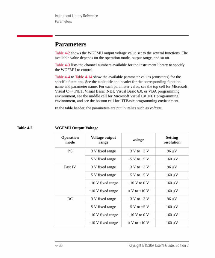
Instrument Library ReferenceParameters
ParametersTable 4-2 shows the WGFMU output voltage value set to the several functions. The available value depends on the operation mode, output range, and so on.
Table 4-3 lists the channel numbers available for the instrument library to specify the WGFMU to control.
Table 4-4 to Table 4-14 show the available parameter values (constants) for the specific functions. See the table title and header for the corresponding function name and parameter name. For each parameter value, see the top cell for Microsoft Visual C++ .NET, Visual Basic .NET, Visual Basic 6.0, or VBA programming environment, see the middle cell for Microsoft Visual C# .NET programming environment, and see the bottom cell for HTBasic programming environment.
In the table header, the parameters are put in italics such as voltage.
Table 4-2 WGFMU Output Voltage
Operation mode
Voltage output range
voltageSetting
resolution
PG 3 V fixed range -3 V to +3 V 96 V
5 V fixed range -5 V to +5 V 160 V
Fast IV 3 V fixed range -3 V to +3 V 96 V
5 V fixed range -5 V to +5 V 160 V
-10 V fixed range -10 V to 0 V 160 V
+10 V fixed range 0 V to +10 V 160 V
DC 3 V fixed range -3 V to +3 V 96 V
5 V fixed range -5 V to +5 V 160 V
-10 V fixed range -10 V to 0 V 160 V
+10 V fixed range 0 V to +10 V 160 V
4-66 Keysight B1530A User’s Guide, Edition 7

Instrument Library ReferenceParameters
Table 4-3 WGFMU Channel Number
chanId Description
101 Ch 1 of the WGFMU installed in the slot 1 (bottom slot)
102 Ch 2 of the WGFMU installed in the slot 1 (bottom slot)
201 Ch 1 of the WGFMU installed in the slot 2
202 Ch 2 of the WGFMU installed in the slot 2
301 Ch 1 of the WGFMU installed in the slot 3
302 Ch 2 of the WGFMU installed in the slot 3
401 Ch 1 of the WGFMU installed in the slot 4
402 Ch 2 of the WGFMU installed in the slot 4
501 Ch 1 of the WGFMU installed in the slot 5
502 Ch 2 of the WGFMU installed in the slot 5
601 Ch 1 of the WGFMU installed in the slot 6
602 Ch 2 of the WGFMU installed in the slot 6
701 Ch 1 of the WGFMU installed in the slot 7
702 Ch 2 of the WGFMU installed in the slot 7
801 Ch 1 of the WGFMU installed in the slot 8
802 Ch 2 of the WGFMU installed in the slot 8
901 Ch 1 of the WGFMU installed in the slot 9
902 Ch 2 of the WGFMU installed in the slot 9
1001 Ch 1 of the WGFMU installed in the slot 10 (top slot)
1002 Ch 2 of the WGFMU installed in the slot 10 (top slot)
Keysight B1530A User’s Guide, Edition 7 4-67
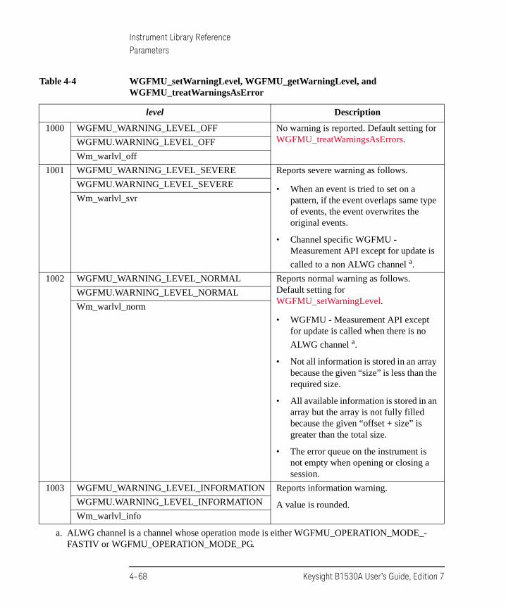
Instrument Library ReferenceParameters
Table 4-4 WGFMU_setWarningLevel, WGFMU_getWarningLevel, and WGFMU_treatWarningsAsError
level Description
1000 WGFMU_WARNING_LEVEL_OFF No warning is reported. Default setting for WGFMU_treatWarningsAsErrors.WGFMU.WARNING_LEVEL_OFF
Wm_warlvl_off
1001 WGFMU_WARNING_LEVEL_SEVERE Reports severe warning as follows.
• When an event is tried to set on a pattern, if the event overlaps same type of events, the event overwrites the original events.
• Channel specific WGFMU - Measurement API except for update is
called to a non ALWG channel a.
a. ALWG channel is a channel whose operation mode is either WGFMU_OPERATION_MODE_-FASTIV or WGFMU_OPERATION_MODE_PG.
WGFMU.WARNING_LEVEL_SEVERE
Wm_warlvl_svr
1002 WGFMU_WARNING_LEVEL_NORMAL Reports normal warning as follows. Default setting for WGFMU_setWarningLevel.
• WGFMU - Measurement API except for update is called when there is no
ALWG channel a.
• Not all information is stored in an array because the given “size” is less than the required size.
• All available information is stored in an array but the array is not fully filled because the given “offset + size” is greater than the total size.
• The error queue on the instrument is not empty when opening or closing a session.
WGFMU.WARNING_LEVEL_NORMAL
Wm_warlvl_norm
1003 WGFMU_WARNING_LEVEL_INFORMATION Reports information warning.
A value is rounded.WGFMU.WARNING_LEVEL_INFORMATION
Wm_warlvl_info
4-68 Keysight B1530A User’s Guide, Edition 7

Instrument Library ReferenceParameters
Table 4-5 WGFMU_setOperationMode and WGFMU_getOperationMode
mode Description
2000 WGFMU_OPERATION_MODE_DC DC mode. DC voltage output and voltage or current measurement (VFVM or VFIM).
The functions of the following group are available in this mode only.
• DC - Measurement
WGFMU.OPERATION_MODE_DC
Wm_opemod_dc
2001 WGFMU_OPERATION_MODE_FASTIV Fast IV mode. ALWG voltage output and voltage or current measurement (VFVM or VFIM).
WGFMU.OPERATION_MODE_FASTIV
Wm_opemod_fast
2002 WGFMU_OPERATION_MODE_PG PG mode. ALWG voltage output and voltage measurement (VFVM). The output voltage will be divided by the internal 50 resistor and the load impedance. Faster than the Fast IV mode.
WGFMU.OPERATION_MODE_PG
Wm_opemod_pg
2003 WGFMU_OPERATION_MODE_SMU SMU mode, default setting
For using SMU connected to the RSU. The functions of the following groups are not available.
• Common - Measurement
• WGFMU - Measurement
• WGFMU - Data retrieve
• DC - Measurement
WGFMU.OPERATION_MODE_SMU
Wm_opemod_smu
Keysight B1530A User’s Guide, Edition 7 4-69

Instrument Library ReferenceParameters
Table 4-6 WGFMU_setForceVoltageRange and WGFMU_getForceVoltageRange
range Description
3000 WGFMU_FORCE_VOLTAGE_RANGE_AUTO Auto range a, default setting
a. Available for the Fast IV, PG, and DC operation mode. Meaningless for the SMU mode.
WGFMU.FORCE_VOLTAGE_RANGE_AUTO
Wm_fovolrng_aut
3001 WGFMU_FORCE_VOLTAGE_RANGE_3V 3 V fixed range a (-3 V to +3 V)WGFMU.FORCE_VOLTAGE_RANGE_3V
Wm_fovolrng_3v
3002 WGFMU_FORCE_VOLTAGE_RANGE_5V 5 V fixed range a (-5 V to +5 V)WGFMU.FORCE_VOLTAGE_RANGE_5V
Wm_fovolrng_5v
3003 WGFMU_FORCE_VOLTAGE_RANGE_10V_NEGATIVE -10 V fixed range b (-10 V to 0 V)
b. Available for the Fast IV and DC operation mode. Meaningless for the SMU mode. Not avail-able for the PG mode.
WGFMU.FORCE_VOLTAGE_RANGE_10V_NEGATIVE
Wm_fovolrng_10n
3004 WGFMU_FORCE_VOLTAGE_RANGE_10V_POSITIVE +10 V fixed range b (0 V to +10 V)WGFMU.FORCE_VOLTAGE_RANGE_10V_POSITIVE
Wm_fovolrng_10p
4-70 Keysight B1530A User’s Guide, Edition 7

Instrument Library ReferenceParameters
Table 4-7 WGFMU_setMeasureMode and WGFMU_getMeasureMode
Table 4-8 WGFMU_setMeasureVoltageRange and WGFMU_getMeasureVoltageRange
mode Description
4000 WGFMU_MEASURE_MODE_VOLTAGE Voltage measurement mode a, default setting
Changing the mode to this mode does not change the current measurement range setting.
a. Available for the Fast IV, PG, and DC operation mode. Meaningless for the SMU mode.
WGFMU.MEASURE_MODE_VOLTAGE
Wm_memod_vol
4001 WGFMU_MEASURE_MODE_CURRENT Current measurement mode b
Changing the mode to this mode changes the voltage measurement range to the 5 V range.
b. Available for the Fast IV and DC operation mode. Meaningless for the SMU mode. Not avail-able for the PG mode.
WGFMU.MEASURE_MODE_CURRENT
Wm_memod_cur
range Description
5001 WGFMU_MEASURE_VOLTAGE_RANGE_5V 5 V fixed range (5 V)
WGFMU.MEASURE_VOLTAGE_RANGE_5V
Wm_mevolrng_5v
5002 WGFMU_MEASURE_VOLTAGE_RANGE_10V 10 V fixed range (10 V), default setting
WGFMU.MEASURE_VOLTAGE_RANGE_10V
Wm_mevolrng_10v
Keysight B1530A User’s Guide, Edition 7 4-71

Instrument Library ReferenceParameters
Table 4-9 WGFMU_setMeasureCurrentRange, WGFMU_getMeasureCurrentRange, and WGFMU_setRangeEvent
range Description
6001 WGFMU_MEASURE_CURRENT_RANGE_1UA 1 A controlled range (1 A)
WGFMU.MEASURE_CURRENT_RANGE_1UA
Wm_mecurrng_1u
6002 WGFMU_MEASURE_CURRENT_RANGE_10UA 10 A controlled range (10 A)
WGFMU.MEASURE_CURRENT_RANGE_10UA
Wm_mecurrng_10u
6003 WGFMU_MEASURE_CURRENT_RANGE_100UA 100 A controlled range (100 A)
WGFMU.MEASURE_CURRENT_RANGE_100UA
Wm_mecurrng_100
6004 WGFMU_MEASURE_CURRENT_RANGE_1MA 1 mA controlled range (1 mA)
WGFMU.MEASURE_CURRENT_RANGE_1MA
Wm_mecurrng_1m
6005 WGFMU_MEASURE_CURRENT_RANGE_10MA 10 mA controlled range (10 mA), default setting
WGFMU.MEASURE_CURRENT_RANGE_10MA
Wm_mecurrng_10m
4-72 Keysight B1530A User’s Guide, Edition 7

Instrument Library ReferenceParameters
Table 4-10 WGFMU_setMeasureEnabled and WGFMU_isMeasureEnabled
Table 4-11 WGFMU_setTriggerOutMode and WGFMU_getTriggerOutMode
status Description
7000 WGFMU_MEASURE_ENABLED_DISABLE Measurement cannot be performed.
WGFMU.MEASURE_ENABLED_DISABLE
Wm_meenable_dis
7001 WGFMU_MEASURE_ENABLED_ENABLE Measurement can be performed. Default setting.
WGFMU.MEASURE_ENABLED_ENABLE
Wm_meenable_ena
mode (8000 to 8004) or polarity (8100/8101) Description
8000 WGFMU_TRIGGER_OUT_MODE_DISABLE No trigger output, default setting
Disables trigger output function.WGFMU.TRIGGER_OUT_MODE_DISABLE
Wm_tgoutmod_dis
8001 WGFMU_TRIGGER_OUT_MODE_START_EXECUTION Execution trigger output mode
Channel outputs trigger only when starting the first sequence output.
WGFMU.TRIGGER_OUT_MODE_START_EXECUTION
Wm_tgoutmod_exe
8002 WGFMU_TRIGGER_OUT_MODE_START_SEQUENCE Sequence trigger output mode
Channel outputs trigger every start of the sequence output.
WGFMU.TRIGGER_OUT_MODE_START_SEQUENCE
Wm_tgoutmod_seq
8003 WGFMU_TRIGGER_OUT_MODE_START_PATTERN Pattern trigger output mode
Channel outputs trigger every start of the pattern output.
WGFMU.TRIGGER_OUT_MODE_START_PATTERN
Wm_tgoutmod_pat
Keysight B1530A User’s Guide, Edition 7 4-73

Instrument Library ReferenceParameters
Table 4-12 WGFMU_createMergedPattern
8004 WGFMU_TRIGGER_OUT_MODE_EVENT Event trigger output mode which enables the trigger output event.
Channel outputs trigger at the timing set by WGFMU_setTriggerOutEvent.
WGFMU.TRIGGER_OUT_MODE_EVENT
Wm_tgoutmod_evt
8100 WGFMU_TRIGGER_OUT_POLARITY_POSITIVE Polarity: positive, default setting
Channel usually outputs TTL low level and outputs TTL high level at the trigger timing.
WGFMU.TRIGGER_OUT_POLARITY_POSITIVE
Wm_tgoutpol_pos
8101 WGFMU_TRIGGER_OUT_POLARITY_NEGATIVE Polarity: negative
Channel usually outputs TTL high level and outputs TTL low level at the trigger timing.
WGFMU.TRIGGER_OUT_POLARITY_NEGATIVE
Wm_tgoutpol_neg
direction Description
9000 WGFMU_AXIS_TIME Time direction. The created pattern will be pattern1 plus pattern2 in this order (in the time direction). The pattern1 last point will be connected to the pattern2 second point. This deletes the pattern2 first point defined by the WGFMU_createPattern function.
WGFMU.AXIS_TIME
Wm_axis_tim
9001 WGFMU_AXIS_VOLTAGE Voltage direction. The created pattern will be pattern1 plus pattern2 in the voltage direction. This is made by adding voltage values together during the period of the longer pattern. For the period over the shorter pattern, the last value of the shorter pattern is used for calculation.
WGFMU.AXIS_VOLTAGE
Wm_axis_vol
mode (8000 to 8004) or polarity (8100/8101) Description
4-74 Keysight B1530A User’s Guide, Edition 7

Instrument Library ReferenceParameters
Table 4-13 WGFMU_isMeasureEventCompleted
Table 4-14 WGFMU_setMeasureEvent
complete Description
11000 WGFMU_MEASURE_EVENT_NOT_COMPLETED Not completed.
WGFMU.MEASURE_EVENT_NOT_COMPLETED
Wm_meevt_notcd
11001 WGFMU_MEASURE_EVENT_COMPLETED Completed. Ready to read result.
WGFMU.MEASURE_EVENT_COMPLETED
Wm_meevt_cd
rdata Description
12000 WGFMU_MEASURE_EVENT_DATA_AVERAGED Averaging data output mode
Only the averaging result data will be returned and the number of returned data will be points.
WGFMU.MEASURE_EVENT_DATA_AVERAGED
Wm_meevtdat_ave
12001 WGFMU_MEASURE_EVENT_DATA_RAW Raw data output mode
All of the measurement data used for averaging will be returned and the number of returned data will be
points (1 + int(average/(5 10-9))).
WGFMU.MEASURE_EVENT_DATA_RAW
Wm_meevtdat_raw
Keysight B1530A User’s Guide, Edition 7 4-75

Instrument Library ReferenceChannel Execution Status
Channel Execution StatusWhen sequencer of the WGFMU channel is running, channel execution status can be monitored by using the following functions.
• WGFMU_getChannelStatus
This function returns the channel status, the elapsed time, and the total time.
• WGFMU_getCompletedMeasureEventSize
This function returns the number of completed measurement events and the total number of measurement events.
• WGFMU_getMeasureValueSize
This function returns the number of completed measurement points and the total number of measurement points.
For an example shown in Table 4-15, the total time, total number of measurement events, and total number of measurement points are calculated as follows.
Total time = 3 10 s + 50 ns + 1 50 s + 50 ns + 2 20 s = 120.1 s
Total number of measurement events = 3 7 + 1 6 + 2 5 = 37 events
Total number of measurement points = 3 7 5 + 1 6 4 + 2 5 3 = 159 points
Where, the required time between sequences is 50 ns.
For example, at the end of the first loop of the sequence 2, the elapsed time, number of completed events, and number of completed points will be as follows.
Elapsed time = 3 10 s + 50 ns + 1 50 s + 50 ns + 1 20 s = 100.1 s
Number of completed events = 3 7 + 1 6 + 1 5 = 32 events
Number of completed points = 3 7 5 + 1 6 4 + 1 5 3 = 144 points
Table 4-15 Example Sequences
Pattern count
Pattern length
Number of events
Points/event for all events
Sequence 0 3 10 s 7 5
Sequence 1 1 50 s 6 4
Sequence 2 2 20 s 5 3
4-76 Keysight B1530A User’s Guide, Edition 7

Instrument Library ReferenceWGFMU Setup Functions
WGFMU Setup FunctionsFunctions of WGFMU Setup group are used to define the WGFMU output voltage waveform and the voltage or current measurement condition and are classified by Pattern, Pattern operation, Event, and Sequence subgroup. See Table 4-1 for the group and the summary of functions.
Parameter values set to the WGFMU Setup functions will be checked as shown below when a function is executed.
• Setup check against the lowest limit
The parameter setup values are checked when each function is executed.
• Setup check against the highest limit
The parameter setup values are checked when one of the following functions is executed.
• WGFMU_execute
• WGFMU_exportAscii
This function cannot check the measurement setup such as the voltage output range, measurement range, and so on.
• WGFMU_update
• WGFMU_updateChannel (effective only for the specified channel)
Keysight B1530A User’s Guide, Edition 7 4-77

Instrument Library ReferenceReturn Codes
Return CodesStatus code of the instrument library is listed in Table 4-17. The code can be returned by the WGFMU_getChannelStatus or WGFMU_getStatus function.
Error code of the instrument library is listed in Table 4-18. The code will be returned by executing the functions. If no error occurs, WGFMU_NO_ERROR will be returned. See WGFMU_getError and WGFMU_getErrorSummary for more details.
Table 4-16 shows the return code of the WGFMU_doSelfCalibration or WGFMU_doSelfTest function.
For the predefined constant for each code in the tables, see the top cell for Microsoft Visual C++ .NET, Visual Basic .NET, Visual Basic 6.0, or VBA programming environment, see the middle cell for Microsoft Visual C# .NET programming environment, and see the bottom cell for HTBasic programming environment.
Table 4-16 Return Codes of WGFMU_doSelfCalibration and WGFMU_doSelfTest
Code Predefined constant Description
0 WGFMU_PASS Self-test passed or self-calibration passed
WGFMU.PASS
Wm_pass
1 WGFMU_FAIL Self-test failed or self-calibration failed
WGFMU.FAIL
Wm_fail
4-78 Keysight B1530A User’s Guide, Edition 7

Instrument Library ReferenceReturn Codes
Table 4-17 Status Codes
Code a
a. Measurement data cannot be read when the channel status is 10005 or 10006.
Predefined constant Description
10000 WGFMU_STATUS_COMPLETED All sequences are completed and all data is ready to read
WGFMU.STATUS_COMPLETED
Wm_status_cd
10001 WGFMU_STATUS_DONE All sequences are just completed
WGFMU.STATUS_DONE
Wm_status_done
10002 WGFMU_STATUS_RUNNING Sequencer is running
WGFMU.STATUS_RUNNING
Wm_status_run
10003 WGFMU_STATUS_ABORT_COMPLETED Sequencer is aborted and all data is ready to read.
WGFMU.STATUS_ABORT_COMPLETED
Wm_status_abcd
10004 WGFMU_STATUS_ABORTED Sequencer is just aborted
WGFMU.STATUS_ABORTED
Wm_status_ab
10005 WGFMU_STATUS_RUNNING_ILLEGAL Illegal state b
b. The channel will enter the illegal state by receiving a function which changes a setup while the sequencer is running. In the illegal state, there is no consistency between the hardware setup and the software setup. However, the channel continues operation of the previous setup.
WGFMU.STATUS_RUNNING_ILLEGAL
Wm_status_runil
10006 WGFMU_STATUS_IDLE Idle state
WGFMU.STATUS_IDLE
Wm_status_idle
Keysight B1530A User’s Guide, Edition 7 4-79

Instrument Library ReferenceReturn Codes
Table 4-18 Error Codes
Code a Predefined constant Description
0 WGFMU_NO_ERROR No error.
WGFMU.NO_ERROR
Wm_no_err
-1 WGFMU_PARAMETER_OUT_OF_RANGE_ERROR Invalid parameter value was found. It will be out of the range. Set the effective parameter value.
WGFMU.PARAMETER_OUT_OF_RANGE_ERROR
Wm_param_err
-2 WGFMU_ILLEGAL_STRING_ERROR Invalid string value was found. It will be empty or illegal (pointer). Set the effective string value.
WGFMU.ILLEGAL_STRING_ERROR
Wm_string_err
-3 WGFMU_CONTEXT_ERROR Context error was found between relative functions. Set the effective parameter value.
WGFMU.CONTEXT_ERROR
Wm_context_err
-4 WGFMU_FUNCTION_NOT_SUPPORTED_ERROR Specified function is not supported by this channel. Set the channel id properly.
WGFMU.FUNCTION_NOT_SUPPORTED_ERROR
Wm_function_err
-5 WGFMU_COMMUNICATION_ERROR IO library error was found.
WGFMU.COMMUNICATION_ERROR
Wm_com_err
-6 WGFMU_FW_ERROR Firmware error was found.
WGFMU.FW_ERROR
Wm_fw_err
-7 WGFMU_LIBRARY_ERROR WGFMU instrument library error was found.
WGFMU.LIBRARY_ERROR
Wm_library_err
4-80 Keysight B1530A User’s Guide, Edition 7
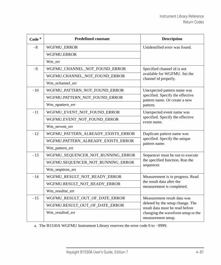
Instrument Library ReferenceReturn Codes
-8 WGFMU_ERROR Unidentified error was found.
WGFMU.ERROR
Wm_err
-9 WGFMU_CHANNEL_NOT_FOUND_ERROR Specified channel id is not available for WGFMU. Set the channel id properly.
WGFMU.CHANNEL_NOT_FOUND_ERROR
Wm_nchannel_err
-10 WGFMU_PATTERN_NOT_FOUND_ERROR Unexpected pattern name was specified. Specify the effective pattern name. Or create a new pattern.
WGFMU.PATTERN_NOT_FOUND_ERROR
Wm_npattern_err
-11 WGFMU_EVENT_NOT_FOUND_ERROR Unexpected event name was specified. Specify the effective event name.
WGFMU.EVENT_NOT_FOUND_ERROR
Wm_nevent_err
-12 WGFMU_PATTERN_ALREADY_EXISTS_ERROR Duplicate pattern name was specified. Specify the unique pattern name.
WGFMU.PATTERN_ALREADY_EXISTS_ERROR
Wm_pattern_err
-13 WGFMU_SEQUENCER_NOT_RUNNING_ERROR Sequencer must be run to execute the specified function. Run the sequencer.
WGFMU.SEQUENCER_NOT_RUNNING_ERROR
Wm_seqntrun_err
-14 WGFMU_RESULT_NOT_READY_ERROR Measurement is in progress. Read the result data after the measurement is completed.
WGFMU.RESULT_NOT_READY_ERROR
Wm_resultnr_err
-15 WGFMU_RESULT_OUT_OF_DATE_ERROR Measurement result data was deleted by the setup change. The result data must be read before changing the waveform setup or the measurement setup.
WGFMU.RESULT_OUT_OF_DATE_ERROR
Wm_resultod_err
a. The B1530A WGFMU Instrument Library reserves the error code 0 to -9999.
Code a Predefined constant Description
Keysight B1530A User’s Guide, Edition 7 4-81

Instrument Library ReferenceError Messages
Error MessagesWhen Keysight B1530A causes errors, the B1530A returns the following error code and error message.
Operation Error3000 WGFMU module does not exist.
Check the channel number of the WGFMU module and set the correct value.
3001 RSU is not connected.
Check the channel number of the WGFMU module connected to the RSU and set the correct value.
3015 Measurement data corrupted.
Cannot get the measurement data. Correct measurement result is not stored in the memory.
3050 Measurement data memory overflow error.
ALWG sequencer run time error. WGFMU module memory overflow occurred. Data exceeds memory size could not be stored.
3051 Measurement data FIFO overflow error.
ALWG sequencer run time error. WGFMU module FIFO overflow occurred because the averaging count was frequently changed.
3052 Measurement range change request error.
ALWG sequencer run time error. Measurement range cannot be changed because the range change interval is too short.
3201 ALWG Sequence Data is not ready.
Sequence data must be set to the specified WGFMU channel.
3202 ALWG Waveform Data is not ready.
Waveform data must be set to the specified WGFMU channel.
4-82 Keysight B1530A User’s Guide, Edition 7

Instrument Library ReferenceError Messages
3301 Specified output voltage is out of absolute limits.
Check the output voltage and set the correct value. The value must be -3 V to +3 V for the 3 V range, -5 V to +5 V for the 5 V range, -10 V to 0 V for the -10 V range, or 0 V to +10 V for the + 10 V range.
3302 Specified voltage output range is invalid.
Check the voltage output range and set the correct value.
3303 Invalid measurement mode for current operation mode.
Operation mode must be Fast IV or DC to perform current measurement.
3304 Specified ALWG Vector Data size is out of absolute limits.
ALWG data cannot be read because of too large data size.
3305 Specified ALWG Sequence Data size is out of absolute limits.
ALWG data cannot be read because of too large sequence data size.
3306 ALWG Waveform Data is empty.
ALWG data must not be empty.
3307 Specified ALWG Waveform Data size is out of absolute limits.
ALWG data cannot be read because of too large waveform data size.
3308 Specified waveform index of ALWG Sequence Data is out of absolute limits.
Check the index value of the sequence data and set the correct value.
3309 Specified loop number of ALWG Sequence Data is out of absolute limits.
Check the loop value of the sequence data and set the correct value.
3310 Specified output voltage of ALWG Waveform Data is out of absolute limits.
Check the output voltage and set the correct value. The value must be -3 V to +3 V for the 3 V range, -5 V to +5 V for the 5 V range, -10 V to 0 V for the -10 V range, or 0 V to +10 V for the + 10 V range.
3311 Specified interval time of ALWG Waveform is out of absolute limits.
Check the incremental time (interval time) and set the correct value. The value must be 10 ns to 10995.11627775 s, in 10 ns resolution.
Keysight B1530A User’s Guide, Edition 7 4-83

Instrument Library ReferenceError Messages
3312 Specified ALWG measurement interval time is out of absolute limits.
Check the measurement interval time and set the correct value. The value must be 10 ns to 1.34217728 s, in 10 ns resolution.
3313 Specified ALWG measurement instruction code is invalid.
Check the measurement event setting and set the correct values.
3314 Specified ALWG range change instruction code is invalid.
Check the range event setting and set the correct values.
3315 Specified ALWG measurement count is out of absolute limits.
Check the measurement averaging time and set the correct value. The value must be 0, or 10 ns to 0.020971512 s, in 10 ns resolution.
3316 Specified ALWG measurement count is greater than measurement interval.
Check the measurement averaging time and set the correct value. The value must less than or equal to the measurement interval time.
3317 Specified slot is invalid.
Check the slot number and set the correct value. The slot number must be 1 to 10.
3318 Specified module channel is invalid.
Check the channel number and set the correct value.
3319 Output delay is out of absolute limits.
Check the output delay and set the correct value. The value must be -50 ns to 50 ns, in 625 ps resolution.
3320 Measurement delay is out of absolute limits.
Check the measurement delay and set the correct value. The value must be -50 ns to 50 ns, in 625 ps resolution.
3321 VM/IM measurement mode is invalid.
Check the measurement mode and set the correct value.
3322 Voltage measurement range is invalid.
Check the voltage measurement range and set the correct value.
3323 Current measurement range is invalid.
Check the current measurement range and set the correct value.
4-84 Keysight B1530A User’s Guide, Edition 7

Instrument Library ReferenceError Messages
3324 WGMA?,WGMB? command query size is out of absolute limits.
Check the data size for WGMA? or WGMB? and set the correct value.
3325 Specified count for spot measurement is out of absolute limits.
Check the count value for WGMS? and set the correct value.
3326 Specified interval for spot measurement is out of absolute limits.
Check the interval value for WGMS? and set the correct value.
3327 Specified operation mode is invalid for spot measurement.
Operation mode must be DC to perform spot measurement.
Self-test/Calibration Error3002 WGFMU initialization failure.
3003 WGFMU FPGA is not configured.
3004 EEPROM CRC data of system timing data is invalid.
3005 EEPROM CRC data of DAC DCM PS data is invalid.
3006 EEPROM CRC data of ADC DCM PS data is invalid.
3007 EEPROM CRC data of DAC clock edge data is invalid.
3008 EEPROM CRC data of ADC clock edge data is invalid.
3009 EEPROM CRC data of DAC level calibration data is invalid.
3010 EEPROM CRC data of ADC level calibration data is invalid.
3011 EEPROM CRC data of DAC skew calibration data is invalid.
3012 EEPROM CRC data of ADC skew calibration data is invalid.
3013 EEPROM CRC data of RSU calibration data is invalid.
3014 Invalid EEPROM type.
3400 WGFMU module is in TEST FAIL state.
3401 Digital H/W function test failed.
3402 CPLD access function test failed.
3403 FPGA configuration test failed.
3404 FPGA1 access function test failed.
Keysight B1530A User’s Guide, Edition 7 4-85

Instrument Library ReferenceError Messages
3405 FPGA2 access function test failed.
3406 FPGA1 System Clock DCM function test failed.
3407 FPGA1 DAC Clock DCM function test failed.
3408 FPGA1 ADC Clock DCM function test failed.
3409 FPGA1 Memory Clock DCM function test failed.
3410 FPGA2 System Clock DCM function test failed.
3411 FPGA2 DAC Clock DCM function test failed.
3412 FPGA2 ADC Clock DCM function test failed.
3413 FPGA2 Memory Clock DCM function test failed.
3414 FPGA1, 2 communication I/F test failed.
3415 CONVEND interrupt function test failed.
3416 10 MHz clock test failed.
3417 FPGA SYNC SEL pin control function test failed.
3418 FPGA SYNC FB pin control function test failed.
3419 FPGA SYNC IN pin control function test failed.
3420 IDELAY function test failed.
3421 Channel 1 SDRAM access function test failed.
3422 Channel 2 SDRAM access function test failed.
3423 WGFMU EEPROM access function test failed.
3424 Channel 1 RSU EEPROM access function test failed.
3425 Channel 2 RSU EEPROM access function test failed.
3426 WGFMU EEPROM CRC data is invalid.
3427 WGFMU EEPROM CRC data of format revision data is invalid.
3428 WGFMU EEPROM CRC data of serial number data is invalid.
3429 WGFMU EEPROM CRC data of system timing data is invalid.
3430 WGFMU EEPROM CRC data of DAC DCM PS data is invalid.
3431 WGFMU EEPROM CRC data of ADC DCM PS data is invalid.
3432 WGFMU EEPROM CRC data of DAC clock edge data is invalid.
4-86 Keysight B1530A User’s Guide, Edition 7

Instrument Library ReferenceError Messages
3433 WGFMU EEPROM CRC data of ADC clock edge data is invalid.
3434 WGFMU EEPROM CRC data of DAC level calibration data is invalid.
3435 WGFMU EEPROM CRC data of ADC level calibration data is invalid.
3436 WGFMU EEPROM CRC data of DAC skew calibration data is invalid.
3437 WGFMU EEPROM CRC data of ADC skew calibration data is invalid.
3438 RSU EEPROM CRC data of format revision data is invalid.
3439 RSU EEPROM CRC data of serial number data is invalid.
3440 RSU EEPROM CRC data of type id data is invalid.
3441 RSU EEPROM CRC data of calibration data is invalid.
3450 WGFMU EEPROM data is invalid.
3451 WGFMU EEPROM data of RSU type is invalid.
3452 WGFMU EEPROM data of RSU cable type is invalid.
3460 Main DAC, Main ADC test failed.
3461 Bias DAC, Main ADC test failed.
3462 Main DAC, Reference ADC test failed.
3463 VM function test failed.
3464 IM offset test failed.
3465 IM short test failed.
3480 Invalid frame configuration.
3481 Invalid frame configuration.
3482 Frame has no modules.
3483 PLL not locked in slave module.
3484 Reference line is not connected.
3485 Sync line is not connected.
3486 Sync Reserve line is not connected.
3487 Interrupt line is not available.
3488 Module service request assertion test failed.
3489 Module service request detection test failed.
Keysight B1530A User’s Guide, Edition 7 4-87

Instrument Library ReferenceError Messages
3490 Emergency interrupt is not available.
3500 WGFMU calibration failed.
3501 ADC gain calibration failed.
3502 CMR calibration failed.
3503 IM offset calibration failed.
3504 VM offset calibration failed.
3505 VF gain calibration failed.
3506 VF offset calibration failed.
3507 Reference ADC does not exist. Cannot perform WGFMU calibration.
3508 WGFMU, RSU cable length calibration failed.
4-88 Keysight B1530A User’s Guide, Edition 7


This information is subject to change without notice.© Keysight Technologies 2008-2015
Edition 7, June 2015
*B1530-90000*B1530-90000
www.keysight.com